-part 1 ansys-1
TRANSCRIPT

BME
NYMU
1
Computer Aided Engineering
-Part 1 ANSYS-1
電腦輔助工程分析
-Part 1 ANSYS-1
林峻立 特聘教授
Chun-Li Lin, Ph.D.
國立陽明大學生物醫學工程系
Department of Biomedical Engineering,
National Yang-Ming University.
2019/02

BME
NYMU
2
Physical Problems
Engineering Problems
Math. Models
Numerical/Analytical
Experimental Models
Setup & Observation
Evaluations
Assumptions
Physical Laws

BME
NYMU
3
Analytical Method
Numerical Method
FEM,BEM, FDM, etc.
Fq
wt
Cross sectiona b
L
y
x
y=Fa3(3L-a)/6EI+q(3L4-4a3L+a4)/24EI
Fundamental Concepts in FEM

BME
NYMU
4
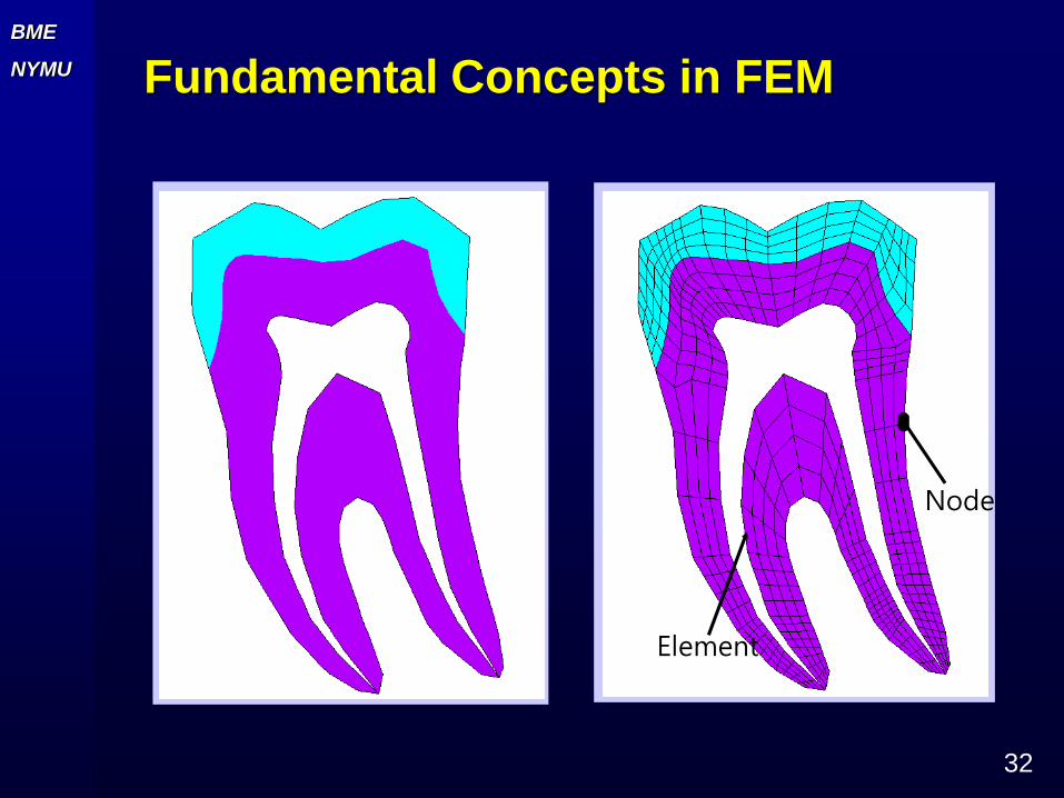
實際的物理問題很難利用單一的微分方程式描述,更無法順利求
其解析(analytical solution)解
有限元素法的精神是將複雜的幾何外型的結構物體切割成許多簡
單的幾何形狀稱之為元素(element)
元素與元素間以“節點”(node)相連
由於元素是簡單的幾何形狀,故可順利寫出元素的力平衡方程式
並求得節點上之變位、應變及應力等
藉由內插法求得元素內任意點的變位、應變及應力等
Fundamental Concepts in FEM

BME
NYMU
5
Fundamental Concepts in FEM
Element
Node

BME
NYMU
6
所謂的CAE是指「computer-aided engineering」之縮寫,中文普
遍稱為「電腦輔助工程」或「電腦輔助工程分析」。大略來說,只要
是應用電腦來模擬分析實際物理問題,均可將其稱為CAE。
CAE之分析類型很多,它包含了結構應力分析、振動分析、流體分析、
熱傳分析、電磁場分析、塑膠射出成型流動分析、鑄造流動分析、機
構運動與動力學分析等。
以固體力學為例,其CAE之主流數值方法為有限元素法(finite
element method, FEM),亦可稱為有限元素分析(finite element
analysis, FEA),它的基本概念是把一個實際的連續性物體做離散化,
分割成許多個元素(elements)與節點(nodes),統稱為網格(mesh),
而每個元素均遵守力學基本理論模式。
General Concept of CAE

BME
NYMU
7
(a)實際工程問題
(b)元素網格
(c)模擬之變形

BME
NYMU
8
CAE和電腦輔助設計(computer-aided design,CAD)與電腦輔助
製造(computer-aided manufacturing, CAM)同屬於電腦輔助之
工具,近年來發展的CAD/CAM/CAE系統已成為工業界產品研發的
利器,尤其成熟的CAD/CAM設計系統早已在許多台灣產業生根。
近年來CAE也逐漸受到國內產業界的重視。面對市場上激烈的競
爭,各公司提升研發能力已是刻不容緩的事,而CAE正可成為提升
研發能力的一大利器。
General Concept of CAE

3C/3R (CAD/CAM/CAE, RE/RP/RT)
Design
Sample
CAD
RE
CAM
CAE
RP RT
IMM
PSM
Produ
ctCMM
ID : Industrial design MMA : Mold manufacturing & analysis
IMM : Injection mould machine PSM : Pressing/shearing machine
QA : Quality assurance
Forward
Engineering
Reverse
Engineering

BME
NYMU
10
CAD\CAE\CAM
General Concept of CAE
CAD CAE CAM

BME
NYMU
11
General Concept of CAE
有限元素法的歷史與軟體應用
有限元素(finite element)」一詞最早出現於1960年,由學者
Clough所提出。
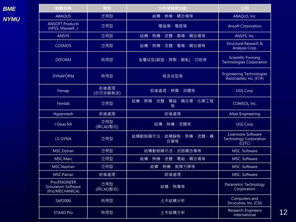
商業化有限元素軟體可分為泛用型(general-purpose)(廣泛分
析型)與特用型(special-purpose)(特定分析)兩大主類(表)
與CAD 整合軟體,通常CAE功能較差(Pro/Engineer)
前後處理器,用來建模及顯示結果(Femap
有限元素分析可應用於結構、熱傳、流體、電磁、耦合場等物
理領域,可應用之行業包括了機械工業、航空工業、土木業、
電子電機業、電腦產業、半導體、微機電、生物科技等。
BME
NYMU
12
軟體名稱 類型 分析領域與功能 公司
ABAQUS 泛用型 結構、熱傳、耦合場等 ABAQUS, Inc.
ANSOFT Products (HFSS, Maxwell…)
泛用型 電磁場、電路等 Ansoft Corporation
ANSYS 泛用型 結構、熱傳、流體、電場、耦合場等 ANSYS, Inc.
COSMOS 泛用型 結構、熱傳、流體、電場、耦合場等Structural Reseach &
Analysis Corp.
DEFORM 特用型 金屬成型(鍛造、擠製、輥軋)、切削等Scientific Forming
Technologies Corporation
DYNAFORM 特用型 板金成型等Engineering Technologies
Associaates, Inc. (ETA)
Femap前後處理
(亦可求解熱流)前後處理、熱傳、流體等 UGS Corp.
Femlab 泛用型結構、熱傳、流體、電磁、耦合場、化學工程
等COMSOL, Inc.
Hypermesh 前後處理 前後處理 Altair Engineering
I-Deas NX泛用型
(與CAD整合)結構、熱傳、流體等 UGS Corp.
LS-DYNA 泛用型結構動態顯示法、結構靜態、熱傳、流體、耦
合場等
Livermore Software Technology Corporation
(LSTC)
MSC.Dytran 泛用型 結構動態顯示法、流固耦合場等 MSC. Software
MSC.Marc 泛用型 結構、熱傳、流體、電磁、耦合場等 MSC. Software
MSC.Nastran 泛用型 結構、熱傳、氣彈力學等 MSC. Software
MSC.Patran 前後處理 前後處理 MSC. Software
Pro/ENGINEER Simulation Software (Pro/MECHANICA)
泛用型(與CAD整合)
結構、熱傳等Parametric Technology
Corporation
SAP2000 特用型 土木結構分析Computers and
Strucutres, Inc. (CSI)
STAAD Pro 特用型 土木結構分析Research Engineers
International

BME
NYMU
13
塑膠椅之力學分析
(a)幾何外形 (b)1/2對稱有限元素模型
(c)變形 (d)應力場

BME
NYMU
14
電腦散熱風扇葉片模態分析

BME
NYMU
15
Biomechanical Analysis of Dental Implant

BME
NYMU
16
Biomechanical Analysis of Dental Implant
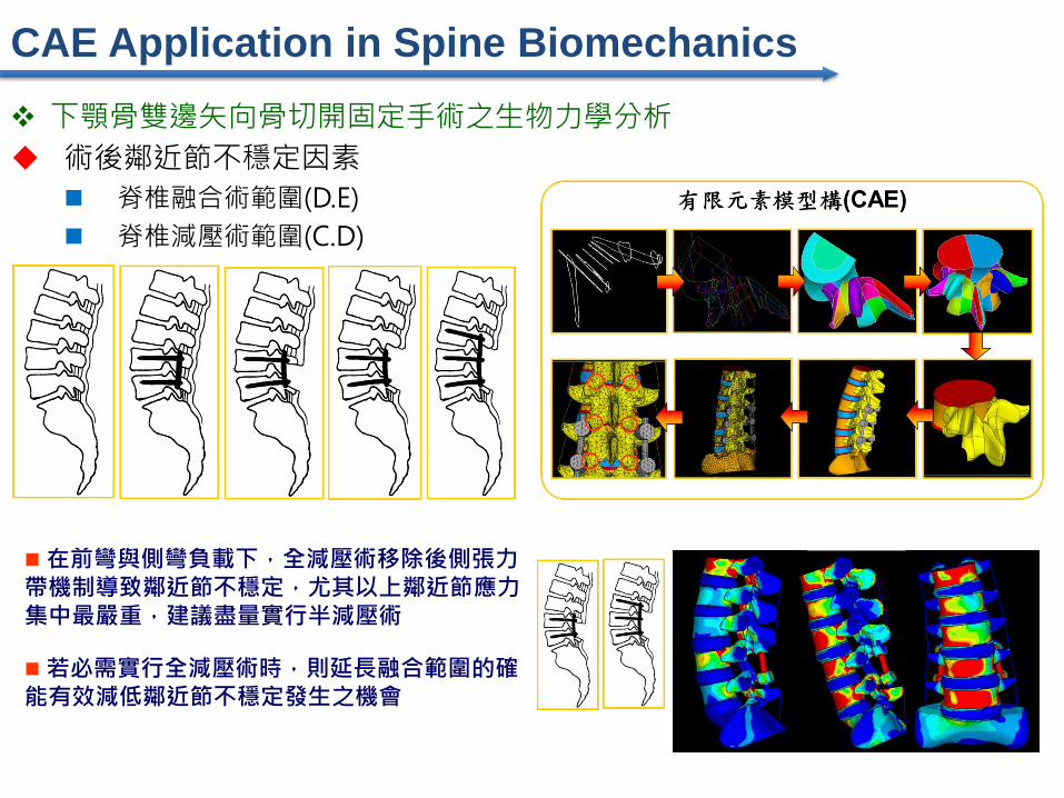
術後鄰近節不穩定因素
脊椎融合術範圍(D.E)
脊椎減壓術範圍(C.D)
下顎骨雙邊矢向骨切開固定手術之生物力學分析
在前彎與側彎負載下,全減壓術移除後側張力帶機制導致鄰近節不穩定,尤其以上鄰近節應力集中最嚴重,建議盡量實行半減壓術
若必需實行全減壓術時,則延長融合範圍的確能有效減低鄰近節不穩定發生之機會
CAE Application in Spine Biomechanics

BME
NYMU
18
Computer Aided Analysis for Bone Remodeling
CAD
CT scan
Femur
Femur
contour
stem solid
model
Stem
implant
Stem contour
3-D Automesh
FE model
CT number

BME
NYMU
19
Computer Aided Analysis for Bone Remodeling
1.7
4
0.0543
750.2175
0.3806
250.5437
50.7068
750.87
1.033
1.196
1.359
1.523
Density g/cm3
Section A
Section B

20
3D modeling for biological structure
W.D.

21
3D modeling for biological structure
C.L. Lin, J.C. Wang*, S.T. Chen, “Evaluation of stress induced of implant type and number of splinted teeth in different periodontal supported tooth-implant supported FPDs: a nonlinear finite element analysis”, Journal of Periodontology, Vol. 81, pp.121-130, 2010.

BME
NYMU
22
FE Package - ANSYS
本課程所應用的有限元素軟體為
ANSYS-Classical
ANSYS WorkBench
ANSYS為一套商業化之泛用型(general-purpose)有限元素分析
軟體
ANSYS是以有限元素法做為數值近似方法,分析功能包括固體力
學、熱傳學、流體力學、電磁學以及跨領域的耦合場(coupled
field)分析等。

BME
NYMU
23
ANSYS Classical 14 之主要模組分類:1. ANSYS Structural
2. ANSYS Mechanical
3. ANSYS Professional
4. ANSYS FLOTRAN
5. ANSYS Emag
FE Package - ANSYS
6. ANSYS Multiphysics
7. ANSYS LS-DYNA
8. ANSYS ED
9. ANSYS Educational
Products
10.ANSYS Design Space
本課程所包括的內容是有限元素法與ANSYS在工程上的應用,範圍以固體力學(solid mechanics)基本模擬分析為主
高等電腦模擬分析
Non-linear structural analysis
Sub-modeling analysis
Element birth and dead
Hyperelasticity
Contact
APDL

BME
NYMU
24
ANSYS使用入門
工作目錄
工作名稱

BME
NYMU
25
記憶體需求

BME
NYMU
26
3工具列
1應用指令功能表列
5圖形視窗
4指令輸入處
2主功能表
6輸出視窗

BME
NYMU
27
ANSYS使用入門
範例步驟,大致可分成以下階段:
1. 分析類型選定2. 元素型式設定
3. 材料性質設定
4. 幾何外形建模
5. 有限元素網格之建立
6. 加入負荷與邊界條件
7. 最後檢查
8. 求解
9. 後處理:觀察分析結果、輸出數據或圖形動畫
所有的有限元素分析軟體都可大略切割成三部分:前處理
器(pre-processor)、求解器(solver)與後處理器(post-
processor)

BME
NYMU
28
ANSYS 使用入門 - Ex1
厚度2mm,左端固定,右端施力F=10N,求應力分佈,材料為鋼(E=210000MPa),Possion’s ratio=0.3

BME
NYMU
29
有限元素分析程序摘要
Fundamental Concepts in FEM
輸入有限元素分析模型
建立每一元素的力平衡方程式
建立整體結構的力平衡方程式
解整體結構力平衡方程式中的節點變位
由節點變位計算應變、應力等
輸出變位、應變及應力等
Pre-processing
Solution
Post-processing

BME
NYMU
30
Pre-processing
Geometry
Mesh (Element type)
Materials
Boundary and loading conditions
Solution
Post-processing
Present the results by graphs…
Fundamental Concepts in FEM

BME
NYMU
31
實際的物理問題很難利用單一的微分方程式描述,更無法順利求
其解析(analytical solution)解
有限元素法的精神是將複雜的幾何外型的結構物體切割成許多簡
單的幾何形狀稱之為元素(element)
元素與元素間以“節點”(node)相連
由於元素是簡單的幾何形狀,故可順利寫出元素的力平衡方程式
並求得節點上之變位、應變及應力等
藉由內插法求得元素內任意點的變位、應變及應力等
Fundamental Concepts in FEM
BME
NYMU
32
Fundamental Concepts in FEM
Element
Node

BME
NYMU
33
元素力平衡方程式[k]{d}={f}
{d}是該元素節點上所有自由度組合而成的向量
{f}稱為元素的力向量
[k]稱為元素的剛度矩陣
整體結構力平衡方程式[K]{D}={F}
{D}是結構上所有自由度組合而成的向量
{F}稱為結構的力向量
[K]稱為結構的剛度矩陣
Fundamental Concepts in FEM

BME
NYMU
34
求出節點的變位後 [k]{d}={f},透過下式可求得應變及應力
z
u
x
u
y
u
z
u
x
u
y
u
x
u
x
u
x
u
xzzx
zy
yz
yxxy
zz
y
y
xx
Fundamental Concepts in FEM
G
G
G
EEE
EEE
EEE
zxzx
yz
yz
xy
xy
yxzz
xzy
y
zyxx

BME
NYMU
35
Fundamental Concepts in FEM

BME
NYMU
36

BME
NYMU
37
Fundamental Concepts in FEM
FEM
A numerical method for solving P.D.E.
Advantage
Can handle
Arbitrary geometry & material complexity
Provide more detailed mechanical responses
Becoming a powerful analytical tool
Disadvantage
Require large amount of input data
Computation time

BME
NYMU
38
The simulated analytical results could be
plausible and incredulous by
inaccurately geometry approximation
material distribution
uncertainty loading and boundary condition
Pre-processing technique of FEM
meshing procedure for bio-structures is still a big
obstacle especially in 3-D applications
Fundamental Concepts in FEM

BME
NYMU
39
Professional Knowledge (Physical Problem)
Structural Mechanics
Thermal (Heat Transform)
Fluid Flow
Electro-magnetic, etc.
CAD CAE
General Concept of CAE
Professional Knowledge

BME
NYMU
40
General Concept of CAE
F=170N
MPa
Max. Principal
Stress
Von-Mises
Stress

BME
NYMU
41
Introduction of ANSYS
選定分析類型

BME
NYMU
42
Introduction of ANSYS
前處理
解題後處理(Post1)
後處理(Post26)
最佳化

BME
NYMU
43
Pre-processing, solution and post-processing

BME
NYMU
44
Introduction of ANSYS工具列 -利用靜態分析各例題說明

BME
NYMU
45
Introduction of ANSYS
Pre-processing
Element type
2D, 3D…
Real Constants
Material Props
Modeling
Model generation techniques
Meshing
Direct generation
Solid modeling
Other techniques
Merge….

BME
NYMU
46
Introduction of ANSYS
Element type definition
The ANSYS element library contains more than 200 different
element types. Each element type has a unique number and a
prefix that identifies the element category: BEAM188,
PLANE183, SOLID186, etc.
2D Triangular Structural Solid 2D Structural Solid 3D Structural Solid
BME
NYMU
47
Introduction of ANSYS
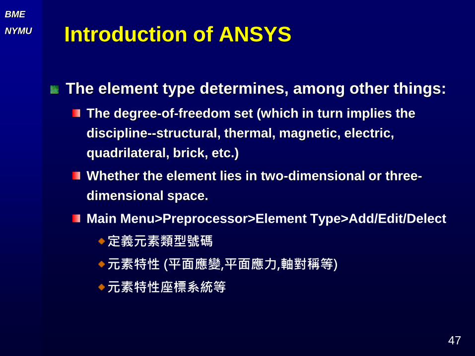
The element type determines, among other things:
The degree-of-freedom set (which in turn implies the
discipline--structural, thermal, magnetic, electric,
quadrilateral, brick, etc.)
Whether the element lies in two-dimensional or three-
dimensional space.
Main Menu>Preprocessor>Element Type>Add/Edit/Delect
定義元素類型號碼
元素特性 (平面應變,平面應力,軸對稱等)
元素特性座標系統等

BME
NYMU
48
Utility Menu
Help
ANSYS Tutorials
ANSYS Web-site
Introduction of ANSYS

BME
NYMU
49
Introduction of ANSYS
ANSYS 重要檔案JOBNAME.DB (Binary)
Node, element, model…..
Results…
JOBNAME.RST or .THR or .RMG (Binary)
Results
JOBNAME.ERR (ASCII)
Error messages
JOBNAME.LOG(ASCII)
Commands

BME
NYMU
50
Introduction of ANSYS
File (demo)
XXX.txt

BME
NYMU
51
Introduction of ANSYS
Plot, List (demo)

BME
NYMU
52
Introduction of ANSYS
PlotCtrls (demo)

BME
NYMU
53
Introduction of ANSYS
圖形控制
檢視圖形
對 X, Y, Z軸旋轉
圖形區域放大
視窗號碼
圖形不同方向示意圖
圖形移動
開啟動態模式
滑鼠右:旋轉
滑鼠左:平移顯示圖形於整個視窗中 回復系統自訂
方向視圖

BME
NYMU
54
2D Plane problem
Plane stress, plane strain, axisymmetric, plane
strs w/thk
Plane stress

BME
NYMU
55
2D Plane problem
Plane strain

BME
NYMU
56
2D Plane problem
Anxisymmetric

BME
NYMU
57
ANSYS 常用平面元素 (PLANE182/183)
PLANE182
PLANE183

BME
NYMU
58
Introduction of ANSYS –Plane182/183

BME
NYMU
59
Introduction of ANSYS
Plane182/183
Plane stress, plane strain,
Axisymmetric, Plane strs w/thk

BME
NYMU
60
Introduction of ANSYS
The first case is called a “plane stress” case,
since
z = xz = yz = 01
X
Y
Z
Corner Bracket (in-lbf-s)
ANSYS 5.6
NOV 25 2000
12:46:12
DISPLACEMENT
STEP=1
SUB =1
TIME=1
PowerGraphics
EFACET=1
AVRES=Mat
DMX =.00121
1
X
Y
Z
DSCA=289.33
ZV =1
DIST=3.882
XF =2.529
YF =-1.617
Z-BUFFER
Corner Bracket (in-lbf-s)
ANSYS 5.6
NOV 25 2000
12:47:34
NODAL SOLUTION
STEP=1
SUB =1
TIME=1
SEQV (AVG)
PowerGraphics
EFACET=1
AVRES=Mat
DMX =.00121
SMN =3.001
SMX =2933
1
MN
MX
X
Y
Z
3.001
328.547
654.093
979.639
1305
1631
1956
2282
2607
2933
Corner Bracket (in-lbf-s)

BME
NYMU
61
Introduction of ANSYS
In the second case, if the cross-sections are
along the radial directions then it is called an
“axisymmetric” case
In the third case, if the cross-sections are along
the thickness then it is called a “plane strain”
case, since
z = xz = yz= 0

BME
NYMU
62
Plane stress example: (Ex 2) (PLANE183)
Static Analysis of a Corner Bracket
This is a simple, single load step, structural static analysis of the
corner angle bracket shown below. The upper left-hand pin hole
is constrained (welded) around its entire circumference, and a
tapered pressure load is applied to the bottom of the lower
right-hand pin hole. The objective of the problem is to demonstrate
the typical ANSYS analysis procedure. The US Customary system
of units is used.

BME
NYMU
63
1
X
Y
Z
Corner Bracket (in-lbf-s)
ANSYS 5.6
NOV 25 2000
12:46:12
DISPLACEMENT
STEP=1
SUB =1
TIME=1
PowerGraphics
EFACET=1
AVRES=Mat
DMX =.00121
1
X
Y
Z
DSCA=289.33
ZV =1
DIST=3.882
XF =2.529
YF =-1.617
Z-BUFFER
Corner Bracket (in-lbf-s)
ANSYS 5.6
NOV 25 2000
12:47:34
NODAL SOLUTION
STEP=1
SUB =1
TIME=1
SEQV (AVG)
PowerGraphics
EFACET=1
AVRES=Mat
DMX =.00121
SMN =3.001
SMX =2933
1
MN
MX
X
Y
Z
3.001
328.547
654.093
979.639
1305
1631
1956
2282
2607
2933
Corner Bracket (in-lbf-s)

BME
NYMU
64
Other plane stress example: (Ex 3)The bicycle wrench shown in figure is made of steel with a
modulus of elasticity E = 200 GPa and Poisson's ratio ν= 0.32. The
wrench is 3 mm thick. Determine the von Mises stresses under the
given distributed load and boundary conditions. The following
steps demonstrate how to (1) create the geometry of the problem .
(2) choose the appropriate element type (3) apply boundary
condition.(4) obtain nodal results.

BME
NYMU
65
Plane strain example: (Ex 4)(PLANE182)
Stresses in a Long Cylinder
A long thick-walled cylinder (with inner radius = 4 in.
and outer radius = 8 in.) is initially subjected to an
constant pressure (of 30000 psi). The pressure is then
removed and the cylinder is subjected to a constant
rotation (60000 rpm) about its center line. Find the radial
displacement, radial stress, and hoop stress at the two
load steps.

BME
NYMU
66
1
STRESSES IN A LONG CYLINDER
Plane strain example: (Ex 4)

BME
NYMU
67
/CLEAR
/TITLE, STRESSES IN A LONG
CYLINDER
/UNITS, BIN
/PREP7
ET, 1, PLANE182,,, 2
MP, EX, 1, 30E6
MP, DENS, 1, .00073
MP, NUXY, 1, 0.3
CSYS, 1 (Cylindrical)
K, 1, 4, 0 (r, degree)
K, 2, 8, 0
K, 3, 4, 45
K, 4, 8, 45
A, 3, 1, 2, 4
ESIZE, .25
MSHK, 1
MSHA, 0, 2D
AMESH, 1 (Mapping)
NROTAT, ALL
FINISH
/SOLU
S, LOC, Y, 0
NSEL, A, LOC, Y, 45
D, ALL, UY, 0
NSEL, S, LOC, X, 4
SF, ALL, PRES, 30000
(Loading)
ALLSEL
/PBC, U,, ON
/PSF, PRES, NORM, 2
EPLOT
SOLVE
NSEL, S, LOC, X, 4
SF, ALL, PRES, 0
(delect)
ALLSEL
OMEGA,,, 1000(rotation)
SOLVE
FINISH
/POST1
SET, 1
PLDISP, 2
RSYS, 1 (Cylindrical)
PLNSOL, S, X
PLNSOL, S, Y
Plane Strain Approach -- commands
Plane strain example: (Ex 4)

BME
NYMU
68
ANSYS 5.6
NOV 26 2000
15:49:49
DISPLACEMENT
STEP=1
SUB =1
TIME=1
PowerGraphics
EFACET=1
AVRES=Mat
DMX =.007623
1
DSCA=37.106
ZV =1
DIST=3.181
XF =5.604
YF =2.892
Z-BUFFER
STRESSES IN A LONG CYLINDER
Plane strain example: (Ex 4)

BME
NYMU
69
Radial Stress
ANSYS 5.6
NOV 26 2000
15:50:18
NODAL SOLUTION
STEP=1
SUB =1
TIME=1
SX (AVG)
RSYS=1
PowerGraphics
EFACET=1
AVRES=Mat
DMX =.007623
SMN =-27596
SMX =-315.425
1
MN
MX
-27596
-24565
-21533
-18502
-15471
-12440
-9409
-6378
-3347
-315.425
STRESSES IN A LONG CYLINDER
Plane strain example: (Ex 4)

BME
NYMU
70
Hoop Stress
ANSYS 5.6
NOV 26 2000
15:50:52
NODAL SOLUTION
STEP=1
SUB =1
TIME=1
SY (AVG)
RSYS=1
PowerGraphics
EFACET=1
AVRES=Mat
DMX =.007623
SMN =19845
SMX =50904
1
MN
MX 19845
23296
26747
30198
33649
37100
40551
44002
47453
50904
STRESSES IN A LONG CYLINDER
Plane strain example: (Ex 4)