parker gen ii r-max™ stream switching system - kinetics · the parker gen ii r-max™ is a...
TRANSCRIPT

Parker Gen II R-max™ Stream Switching SystemCatalog 4141-R March 2013

Parker Hannifin CorporationInstrumentation Products DivisionJacksonville, AL USAhttp://www.parker.com/ipdus
Catalog 4141-RParker Gen II R-max ™ Stream Switching System
© Copyright 2013 Parker Hannifin Corporation. All Rights Reserved.
Offer of SaleThe items described in this document are hereby offered for sale by Parker-Hannifin Corporation, its subsidiaries or its authorized distributors. This offer and its acceptance are governed by the provisions stated in the detailed “Offer of Sale” elsewhere in this document or available at www.parker.com/ipdus.
WARNING – USER RESPONSIBILITYFAILURE OR IMPROPER SELECTION OR IMPROPER USE OF THE PRODUCTS DESCRIBED HEREIN OR RELATED ITEMS CAN CAUSE DEATH, PERSONAL INJURY AND PROPERTY DAMAGE.
This document and other information from Parker-Hannifin Corporation, its subsidiaries and authorized distributors provide product or system options for further investigation by users having technical expertise.
The user, through its own analysis and testing, is solely responsible for making the final selection of the system and components and assuring that all performance, endurance, maintenance, safety and warning requirements of the application are met. The user must analyze all aspects of the application, follow applicable industry standards, and follow the information concerning the product in the current product catalog and in any other materials provided from Parker or its subsidiaries or authorized distributors.
To the extent that Parker or its subsidiaries or authorized distributors provide component or system options based upon data or specifications provided by the user, the user is responsible for determining that such data and specifications are suitable and sufficient for all applications and reasonably foreseeable uses of the components or systems.

1 Parker Hannifin CorporationInstrumentation Products DivisionJacksonville, AL USAhttp://www.parker.com/ipdus
Catalog 4141-R Parker Gen II R-max ™ Stream Switching System
Table of ContentsIntroduction .......................................................................................................................... 2Features & Specifications.................................................................................................... 2
Actuation Pressure vs. System Pressure ....................................................................... 2Exterior Dimensions ............................................................................................................ 3Available End Connections ................................................................................................. 3Valve Module Exploded View .............................................................................................. 4Materials of Construction .................................................................................................... 4Valve Modules .................................................................................................................... 5
Features .......................................................................................................................... 5Flow Diagram (actuated & un-actuated) ........................................................................ 5
Valve Expansion Module ..................................................................................................... 5Surface Mount Module Disassembly ............................................................................. 5
Multiple Stream Switching ................................................................................................... 6Fast Loop Options ............................................................................................................... 6
Internal Fast Loop ........................................................................................................... 6Fast Loop Filters ............................................................................................................. 6
Stream Switch with ARV Module ........................................................................................ 7ARV Module Function .................................................................................................... 7
Atmospheric Reference Vent (ARV Module) ....................................................................... 8Backwards Compatibility ..................................................................................................... 8Captured Vent ...................................................................................................................... 9Enhanced Position Indicator................................................................................................ 9How to Order Stream Switching Systems and Accessories ............................................ 10
Stream Switching Systems Additional Options ............................................................ 10Stream Switching System Kits ..................................................................................... 11
Single Valve ....................................................................................................................... 13How to Order Single Valve ................................................................................................ 14
Additional Options ........................................................................................................ 14Single Valve Kits ........................................................................................................... 15
Fast Loop Filters ................................................................................................................ 16Exterior View and Dimensions ..................................................................................... 16Cross Section View ...................................................................................................... 17Materials of Construction ............................................................................................. 17
How to Order Fast Loop Filters ......................................................................................... 18Additional Options ........................................................................................................ 18Fast Loop Filter Kits ...................................................................................................... 19
Application: Dual ARV Modules ........................................................................................ 20Application: CEMS ............................................................................................................. 21Parker Gen II R-Max™ Stream Switching System & Parker IntraFlow™ ........................ 22Offer of Sale ...................................................................................................................... 24Parker Motion & Control Technologies ...................................................... inside back cover

2 Parker Hannifin CorporationInstrumentation Products DivisionJacksonville, AL USAhttp://www.parker.com/ipdus
Catalog 4141-RParker Gen II R-max ™ Stream Switching System
IntroductionThe Parker Gen II R-max™ is a multi-functional system capable of integrating both stream switching and filtering into one unique compact assembly. The system is designed to control both gases and liquids in analytical systems ranging from vacuum to 500 psig (34 bar) while requiring only 65 psig (5 bar) actuat-ing air pressure. The system was engineered with a focus on improved product reliability and reduced cost of ownership. The Parker Gen II R-max™ Stream Switching System utilizes state-of-the-art surface mount technology to reduce leak paths, internal volume, and dead volume. With surface mounting, system components may be easily removed and replaced without breaking process connections. In addition, the Parker Gen II R-max™ system utilizes an internal self-purging outlet header to eliminate the need for an additional outlet loop.
SpecificationsPressure Rating
500 psig (34 bar) CWP
Temperature RatingFluorocarbon Rubber –
-15°F to 400°F (-26°C to 204°C)Buna-N Rubber –
-30°F to 275°F (-34°C to 135°C)Ethylene Propylene Rubber –
-70°F to 275°F (-57°C to 135°C)Neoprene Rubber –
-45°F to 250°F (-43°C to 121°C)Highly Fluoronated Fluorocarbon Rubber –
-25°F to 300°F (-32°C to 150°C)
Flow Data (in a two stream system)Stream 1: Cv = 0.154Stream 2: Cv = 0.104
Features• Captured vent provides a low pressure header
that separates sample stream from actuation air preventing cross contamination.
• Enhanced position indicator enables easy recognition of valve position for maximum system safety.
• Backward compatibility allows the enhanced features to be added to existing units.
• Surface mount technology enhances maximum system flexibility and enables the user to add additional streams to a system without interrupting installed units.
• Low internal volume insures maximum system efficiency by reducing purge time and expensive purge gas.
• Modular valve design offers maximum serviceability for quick and easy in-system repair and reduced downtime.
• TheGenIIR-Max™ is available for ANSI/ISA-76.00.02 (NeSSI) mounting.
• US Patent 6619321
Actuation Pressure vs. System Pressure

3 Parker Hannifin CorporationInstrumentation Products DivisionJacksonville, AL USAhttp://www.parker.com/ipdus
Catalog 4141-R Parker Gen II R-max ™ Stream Switching System
Note: Actuator air porting and vent porting is always 1/8" FNPT.
Exterior Dimensions
Available End Connections4A7 – 1/4" inverted two ferrule A-LOK® compression port
2F – 1/8" ANSI/ASME B1.20.1 internal pipe threads
4Z7 – 1/4" inverted single ferrule CPI™ compression port

4 Parker Hannifin CorporationInstrumentation Products DivisionJacksonville, AL USAhttp://www.parker.com/ipdus
Catalog 4141-RParker Gen II R-max ™ Stream Switching System
Materials of Construction
Valve Module Exploded View
Item Part Description Material1 Base ASTM A 479, type 3162 Valve Body ASTM A 479, type 3163 Stem ASTM A 479, type 3164 Seat PCTFE5 Backseat PCTFE6 2-013 O-Ring Optional elastomers7 Lower Bonnet ASTM A 479, type 3168 2-007 O-Ring Optional elastomers9 Backup Ring PTFE10 Center Bonnet ASTM A 479, type 31611 2-017 O-Ring Optional elastomers
Item Part Description Material12 Upper Bonnet ASTM A 479, type 31613 2-018 O-Ring Optional elastomers14 2-023 O-Ring Optional elastomers15 Piston ASTM B 611, Alloy 606116 Indicator Flexible polyolefin17 2-020 O-Ring Optional elastomers18 Spring ASTM A 546, type 63019 Cap ASTM B 211, Alloy 606120 Bolt (6-32 x 2.25) Stainless steel21 Bolt (6-32 x 5/16) Stainless steel
Note: Material for Stream Switching Vent and Analyzer End Plates (not shown) is ASTM A 479, type 316. Material for Base Plate Bolts is ASTM A 276, type 316.
Lubrication: Perfluorinated polyether

5 Parker Hannifin CorporationInstrumentation Products DivisionJacksonville, AL USAhttp://www.parker.com/ipdus
Catalog 4141-R Parker Gen II R-max ™ Stream Switching System
Valve ModuleThe Parker Gen II R-max™ Stream Switching System centers around the Valve Module, which contains two 3-way valves. Each Valve Module is factory mounted to a base plate configured to provide the desired function. The Stream Switching Valve Module provides a double block and bleed arrangement preventing cross contamination of the sample streams.
Valve Module Features• EachValveModulehasaflowinlet(1/8"FNPT
or 1/4" Inverted Compression) and a 1/8" FNPT valve air actuation port.
• EachValveModuleemploystwovalves.
Valve Expansion Module – R3EMValve Expansion Modules may be added or removed from the Parker Gen II R-max™ Stream Switching System. The Valve Expansion Module consists of a Valve Module plus two base plate bolts. They may be inserted between the vent and analyzer end plates to add one or more streams to a system. (See How to Order on pages 10-12.)
Note: Valve Modules may only be added to an existing stream switching system.
Valve Module Flow Diagram

6 Parker Hannifin CorporationInstrumentation Products DivisionJacksonville, AL USAhttp://www.parker.com/ipdus
Catalog 4141-RParker Gen II R-max ™ Stream Switching System
Multi-Stream Switch – R3A Multi-Stream Switch consists of individual Valve Modules bolted together between vent and analyzer end plates to create an internal, self-purging system with an integral outlet header. This unique design eliminates dead volume and the need for an external loop.
Fast Loop Options
Internal Fast LoopExample shown is a three stream switching system with an internal fast loop that maintains the double block and bleed feature. Illustrates Streams 1 and 3 in the “off” position, with these two streams flowing to the common vent. Stream 2 is illustrated in the “on” position, closing the bypass and directing the flow to the analyzer. To order, add the suffix -IF to the end of the Stream Switching System part number. (How to Order; see pages 10-12.)
Example: 2F-R3K-BN-SS-3-IF
Fast Loop FiltersExample shown is a three stream switching system with two filter bypasses. Bypass Filter Kits may be incorporated into the Parker Gen II R-max™ Stream Switching System to enhance your system design. (How to Order; see pages 10-12 and 18-19.)

7 Parker Hannifin CorporationInstrumentation Products DivisionJacksonville, AL USAhttp://www.parker.com/ipdus
Catalog 4141-R Parker Gen II R-max ™ Stream Switching System
Stream Switch with ARV ModuleThe ARV Module (Atmospheric Reference Vent) is positioned between the analyzer and stream switch-ing units for sample shut-off and equilibration of the sample loop pressure to atmosphere. This insures a consistent sample pressure in repetitive analysis. When the ARV Module is actuated, the sample flows from the actuated (open) stream, through the GC analyzer and is routed to the low pressure header.
ARV Module Function – Three Stream Examples
Example 1All valves are in the “off” position. The system is “open” to vent.
Example 2Stream 2 and the ARV Module are in the “on” position, purging the sample loop to the low pressure header.
Example 3Stream 2 is in the “on” position and the ARV Module is in the “off” position, equilibrating the sample loop pressure to vent pressure.

8 Parker Hannifin CorporationInstrumentation Products DivisionJacksonville, AL USAhttp://www.parker.com/ipdus
Catalog 4141-RParker Gen II R-max ™ Stream Switching System
Atmospheric Reference Vent (ARV) ModuleThe Atmospheric Reference Vent Module provides many advantages and benefits within a modular footprint. It can be installed inline with existing Stream Switching Modules or act as a stand alone unit. The improved features on the Stream Switching Units are included on the ARV Modules. It is provided with a new end block which has a dedicated atmosphere reference port and the re-designed ARV Mod-ules can be used with Fast Loop Filtration.
Backwards CompatibilityAspects of the R3 Series Gen II R-max ™ can be applied for use with existing R2 Series units. Retrofit-ting the existing R2 Series R-max ™ is easily accomplished by following the provided instructions.
Valve Modules: The valve modules are maintained using four 6-32 bolts. Removing these allows the existing R2 Series Module to be removed and the new R3 Series Module to be installed with new 6-32 bolts.
Position Indicator: The Enhanced Position Indicator used on the R3 Series Gen II R-max ™ provides a yellow indicator that is easily identifiable against a black background. This Indicator can be fitted onto the R2 Series R-max ™ for the same easy identification of valve position.
Redesigned ARV (Atmospheric Reference Vent) Option: R2 Series Stream Select Units can be installed with the redesigned ARV End Plate. Note, this also requires a special stream select module to block the ARV Port from the Vent Port.
9 Parker Hannifin CorporationInstrumentation Products DivisionJacksonville, AL USAhttp://www.parker.com/ipdus
Catalog 4141-R Parker Gen II R-max ™ Stream Switching System
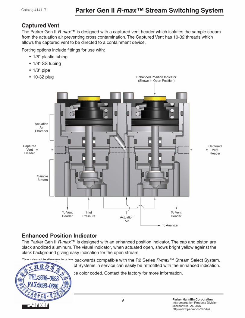
Captured VentThe Parker Gen II R-max ™ is designed with a captured vent header which isolates the sample stream from the actuation air preventing cross contamination. The Captured Vent has 10-32 threads which allows the captured vent to be directed to a containment device.
Porting options include fittings for use with:
• 1/8"plastictubing
• 1/8"SStubing
• 1/8"pipe
• 10-32plug
Enhanced Position IndicatorThe Parker Gen II R-max ™ is designed with an enhanced position indicator. The cap and piston are black anodized aluminum. The visual indicator, when actuated open, shows bright yellow against the black background giving easy indication for the open stream.
The visual indicator is also backwards compatible with the R2 Series R-max ™ Stream Select System. Any R-max ™ Stream Select Systems in service can easily be retrofitted with the enhanced indication.
The position indicator can be color coded. Contact the factory for more information.
10 Parker Hannifin CorporationInstrumentation Products DivisionJacksonville, AL USAhttp://www.parker.com/ipdus
Catalog 4141-RParker Gen II R-max ™ Stream Switching System
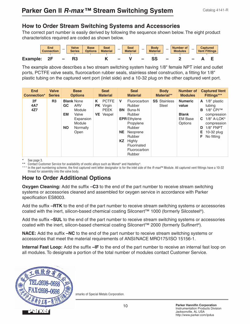
How to Order Stream Switching Systems and AccessoriesThe correct part number is easily derived by following the sequence shown below. The eight product characteristics required are coded as shown below.
How to Order Additional OptionsOxygen Cleaning: Add the suffix –C3 to the end of the part number to receive stream switching systems or accessories cleaned and assembled for oxygen service in accordance with Parker specification ES8003.
Add the suffix –RTK to the end of the part number to receive stream switching systems or accessories coated with the inert, silicon-based chemical coating Silconert™ 1000 (formerly Silcosteel®).
Add the suffix –SUL to the end of the part number to receive stream switching systems or accessories coated with the inert, silicon-based chemical coating Silconert™ 2000 (formerly Sulfinert®).
NACE: Add the suffix –NC to the end of the part number to receive stream switching systems or accessories that meet the material requirements of ANSI/NACE MRO175/ISO 15156-1.
Internal Fast Loop: Add the suffix –IF to the end of the part number to receive an internal fast loop on all modules. To designate a portion of the total number of modules contact Customer Service.
Example: 2F – R3 K – V – SS – 2 – A E
The example above describes a two stream switching system having 1/8" female NPT inlet and outlet ports, PCTFE valve seats, fluorocarbon rubber seals, stainless steel construction, a fitting for 1/8" plastic tubing on the captured vent port (inlet side) and a 10-32 plug on the other captured vent port.
End Connection*
Valve Series
Base Options
Seat Material
Seal Material
Body Material**
Number of Modules
Captured Vent Fittings***
2F4A74Z7
R3 Blank NoneGC ARV ModuleEM Valve Expansion ModuleNO Normally Open
K PCTFEPK Virgin PEEKVE Vespel
V Fluorocarbon RubberBN Buna-N RubberEPR Ethylene Propylene RubberNE Neoprene RubberKZ Highly Fluorinated Fluorocarbon Rubber
SS Stainless Steel
Numeric value
Blank EM Base Options
A 1/8" plastic tubingB 1/8" CPI™ compressionC 1/8" A-LOK® compressionD 1/8" FNPTE 10-32 plugF No fitting
* See page 3. ** Contact Customer Service for availability of exotic alloys such as Monel® and Hastelloy®.*** In the part numbering scheme, the first captured vent letter designator is for the inlet side of the R-max™ Module. All captured vent fittings have a 10-32 thread for assembly into the valve body.
Seal Material
Valve Series
Seat Material
Base Options
End Connection
— — — Captured Vent Fittings
Body Material
— Number of Modules
—
Monel® and Hastelloy® are registered trademarks of Special Metals Corporation.

11 Parker Hannifin CorporationInstrumentation Products DivisionJacksonville, AL USAhttp://www.parker.com/ipdus
Catalog 4141-R Parker Gen II R-max ™ Stream Switching System
How to Order KitsIn using this section, the items in BOLD CAPITALIZED PRINT are included within the part number of the Kit. The italicized items require a designator to complete the part number. Refer to the How To Order section on page 10 for the designators.
Stem Seal Kit: Components required to rebuild the soft goods in one cartridge.
Example: KIT – R3 K – V – SS
This example describes a kit consisting of one stainless steel stem with PCTFE upper and lower seats, fluorocarbon O-rings, associated PTFE back-up rings and maintenance instructions.
Note: This kit is also used for Single Valve Cartridge maintenance.
Seal MaterialR3 Seat
MaterialKIT — — — Body Material
Valve Module Kit: Components required to rebuild the soft goods in one valve module. This includes the base and cartridges.
Example: KIT – R3 EM K – BN – SS
This example describes a kit consisting of two stainless steel stems with PCTFE upper and lower seats, Buna-N O-rings, associated PTFE back-up rings and maintenance instructions.
Note: For kit part numbers, choose GC, NO and EM for the base option.
Seal MaterialR3 Base
OptionsKIT — — — Body Material
Seat Material
Valve Cartridge Kit: Components to replace one valve cartridge.
Example: KIT – R3 K – CART – EPR – SS
This example describes a kit consisting of one completely assembled valve cartridge having PCTFE seats, ethylene propylene O-rings, stainless steel metallic components and maintenance instructions.
Seal MaterialR3 Seat
MaterialKIT — — — Body MaterialCART—
Valve Body Kit: Components required to replace one valve body assembly. This includes the cartridges.
Example: KIT – R3 K – BODY – V – SS
This example describes a kit consisting of one complete valve body and cartridge assembly having PCTFE seats, fluorocarbon O-rings, stainless steel metallic components and maintenance instructions.
Note: The springs, screws and caps are included, but not assembled.
Seal MaterialR3 Seat
MaterialKIT — — — Body MaterialBODY—
Kits continued on the following page.

12 Parker Hannifin CorporationInstrumentation Products DivisionJacksonville, AL USAhttp://www.parker.com/ipdus
Catalog 4141-RParker Gen II R-max ™ Stream Switching System
How to Order Kits (continued)
Base Seal Kit: Components to replace the soft goods in one base.
Example: KIT – R3 GC – BASE – SEALS – KZ
This example describes a kit consisting of highly fluorinated fluorocarbon O-rings and maintenance instructions.
Note: For the base option, choose GC, EM or NO.
SEALSR3 Base OptionsKIT — — — Seal
MaterialBASE—
End Block Seal Kit: Components to replace the soft goods in one end block.
Example: KIT – R3 EM – END – SEALS – V
This example describes a kit consisting of fluorocarbon O-rings and maintenance instructions.
Note: For the base option, choose GC or EM.
SEALSR3KIT — — — Seal Material
—
Position Indication Kits: The R3 Series Gen II R-max™ Position Indicator is backwards compatible to R2 Series R-max™ Units. Simply remove the piston and cap from an existing R2 Series Cartridge and replace with the R3 Series piston and cap. Functionality and performance will remain the same but will include enhance visual awareness of when the unit is actuated open.
Example: KIT – R3 – EPI – V
This example describes a kit consisting of enhanced visual indicator piston and cap, fluorocarbon O-ring and maintenance instructions.
R3KIT — — Seal MaterialEPI—
Base Options END

13 Parker Hannifin CorporationInstrumentation Products DivisionJacksonville, AL USAhttp://www.parker.com/ipdus
Catalog 4141-R Parker Gen II R-max ™ Stream Switching System
Single ValveThe Parker Gen II R-max ™ Single Valve shares the same technology, features, and options found in the Stream Switching System. The pneumatically actuated valve serves as a three-way diverting valve with common, normally open, and normally closed porting.
External Dimensions
Exploded View
The Single Valve shares similar components with the Double Block and Bleed Unit. With the exception of the Valve Body and Base, the components are identical and can be identified using the numbering system on page 4. Materials are identical and also can be identified on page 4.

14 Parker Hannifin CorporationInstrumentation Products DivisionJacksonville, AL USAhttp://www.parker.com/ipdus
Catalog 4141-RParker Gen II R-max ™ Stream Switching System
How to Order – Single ValveThe correct part number is easily derived by following the sequence shown below. The six product characteristics required are coded as shown below.
How to Order Additional OptionsOxygen Cleaning: Add the suffix –C3 to the end of the part number to receive stream switching systems or accessories cleaned and assembled for oxygen service in accordance with Parker Specification ES8003.
Add the suffix –RTK to the end of the part number to receive stream switching systems or accessories coated with the inert, silicon-based chemical coating Silconert™ 1000 (formerly Silcosteel®).
Add the suffix –SUL to the end of the part number to receive stream switching systems or accessories coated with the inert, silicon-based chemical coating Silconert™ 2000 (formerly Sulfinert®).
NACE: Add the suffix –NC to the end of the part number to receive stream switching systems or accessories that meet the material requirements of ANSI/NACE MRO175/ISO 15156-1.
Example: 2F – R3S K – V – SS – A
The example above describes and a two stream switching system having 1/8" female NPT inlet and outlet ports, PCTFE valve seats, fluorocarbon rubber seals, stainless steel construction and fitting for 1/8" plastic tubing on the captured vent.
End Connection*
Valve Series
Seat Material
Seal Material
Body Material**
Captured Vent Fittings***
2F4A74Z7
R3S K PCTFEPK Virgin PEEKVE Vespel
V Fluorocarbon RubberBN Buna-N RubberEPR Ethylene Propylene RubberNE Neoprene RubberKZ Highly Fluorinated Fluorocarbon Rubber
SS Stainless Steel A 1/8" plastic tubingB 1/8" CPI™ compressionC 1/8" A-LOK® compressionD 1/8" FNPTE 10-32 plugF No fitting
* See page 3. ** Contact Customer Service for availability of exotic alloys such as Monel® and Hastelloy®.*** Only one captured vent fitting is required for the single valve. All fittings have a 10-32 thread for assembly into the valve body.
Seal Material
Valve Series
Seat Material
End Connection
— — — Captured Vent Fittings
Body Material
—
Monel® and Hastelloy® are registered trademarks of Special Metals Corporation.

15 Parker Hannifin CorporationInstrumentation Products DivisionJacksonville, AL USAhttp://www.parker.com/ipdus
Catalog 4141-R Parker Gen II R-max ™ Stream Switching System
How to Order Kits – Single ValveIn using this section, the items in BOLD CAPITALIZED PRINT are included within the part number of the Kit. The italicized items require a designator to complete the part number. Refer to the How To Order section on page 14 for the designators.
Stem Seal Kit: Components required to rebuild the soft goods in one cartridge.
Example: KIT – R3 K – V – SS
This example describes a kit consisting of one stainless steel stem with PCTFE upper and lower seats, fluorocarbon O-rings, associated PTFE back-up rings and maintenance instructions.
Seal MaterialR3 Seat
MaterialKIT — — — Body Material
Valve Body Kit: Components to replace one valve body and cartridges.
Example: KIT – R3S K – BODY – V – SS
This example describes a kit consisting of one complete valve body and cartridge having PCTFE seats, fluorocarbon O-rings, stainless steel metallic components and maintenance instructions.
Note: The springs, screw and caps are included, but not assembled.
Seal MaterialR3S Seat
MaterialKIT — — — Body MaterialBODY—
Valve Module Kit: Components to rebuild the soft goods in one Single Valve Module. This includes the base and cartridges.
Example: KIT – R3S K – V – SS
This example describes a kit consisting of one stainless steel stem with PCTFE upper and lower seats, fluorocarbon O-rings, associated PTFE back-up rings and maintenance instructions.
Seal MaterialR3S Seat
MaterialKIT — — — Body Material
Base Seal Kit: Components to replace the soft goods in one base.
Example: KIT – R3S – BASE – SEALS – KZ
This example describes a kit consisting of highly fluorinated fluorocarbon O-rings and maintenance instructions.
SEALSR3SKIT — — — Seal MaterialBASE—

16 Parker Hannifin CorporationInstrumentation Products DivisionJacksonville, AL USAhttp://www.parker.com/ipdus
Catalog 4141-RParker Gen II R-max ™ Stream Switching System
Fast Loop FiltersDesigned to be used on the stream inlet ports of the Parker Gen II R-max ™ Stream Switching System. Multiple filtration options are available using technology developed and designed by Parker Filtration and Separation Divisions. Filtration options include particulate, coalescing and SS sintered.
The particulate filter is housed in a bypass filter that diverts approximately 90% of the inlet flow around the cartridge filter and provides fresh filtered media to the stream switch.
The coalescing filter allows liquid droplets to collect and drain from the media as it enters the stream switch.
The SS sintered filters are designed to protect the Stream Switching System from dirt, chips, scale and other contaminants.
Exterior View and Dimensions

17 Parker Hannifin CorporationInstrumentation Products DivisionJacksonville, AL USAhttp://www.parker.com/ipdus
Catalog 4141-R Parker Gen II R-max ™ Stream Switching System
Cross Section View
Materials of ConstructionItem Part Description Material
1 Body ASTM A 479, type 3162 Bowl ASTM A 479, type 3163 Adapter ASTM A 479, type 3164 O-Ring 2-008 Optional elastomers5 Body Bolt Stainless steel6 O-Ring 2-025 Optional elastomers7 Element 316SS and Microfibre8 Support Core 316SS
Note: The captured vent port nearest an assembled filter must be a plug or an open port.
Fast Loop FiltersDesigned to bolt directly to the stream inlet ports of the Parker Gen II R-max ™ Stream Switching System to provide reduced transport time of filtered sample stream media from the process line through the stream switch to the analyzer.

18 Parker Hannifin CorporationInstrumentation Products DivisionJacksonville, AL USAhttp://www.parker.com/ipdus
Catalog 4141-RParker Gen II R-max ™ Stream Switching System
How to Order – Fast Loop FiltersThe correct part number is easily derived by following the sequence shown below. The seven product characteristics required are coded as shown below.
Example: 2F – FR2 – EPR – S 100 – SS – B
The example above describes an FR2 Series Fast Loop Filter with 1/8" FNPT inlet and bypass outlets, ethylene propylene rubber seals, 100 micron 316SS sintered metal filter element and stainless steel construction. It is designed to be attached to a Parker Gen II R-max ™ Stream Switch having inverted CPI™ or A-LOK® stream inlet ports.
Inlet and Bypass Outlet
Filter Series
Seal Material
Filtration Type
Element Type
Body Material
R-max ™ Connection
TypeBalston® (P and C)
Sintered Metal (S)
2F FR2 V Fluorocarbon RubberBN Buna-N RubberEPR Ethylene Propylene RubberNE Neoprene RubberKZ Highly Fluorinated Fluorocarbon Rubber
P ParticulateC CoalescingS Sintered
93 93% microfibre99 99% microfibre
100 100 micron 70 70 micron 40 40 micron 20 20 micron 10 10 micron 5 5 micron
SS Stainless Steel
A 2FB 4A7 or 4Z7
Filtration Type
Filter Series
Seal Material
Inlet and Bypass Outlet
— — R-max ™ Connection Type
Element Type
— Body Material
——
How to Order Additional OptionsOxygen Cleaning: Add the suffix –C3 to the end of the part number to receive stream switching systems or accessories cleaned and assembled for oxygen service in accordance with Parker specification ES8003.
Add the suffix –RTK to the end of the part number to receive stream switching systems or accessories coated with the inert, silicon-based chemical coating Silconert™ 1000 (formerly Silcosteel®).
Add the suffix –SUL to the end of the part number to receive stream switching systems or accessories coated with the inert, silicon-based chemical coating Silconert™ 2000 (formerly Sulfinert®).
NACE: Add the suffix –NC to the end of the part number to receive stream switching systems or accessories that meet the material requirements of ANSI/NACE MRO175/ISO 15156-1.

19 Parker Hannifin CorporationInstrumentation Products DivisionJacksonville, AL USAhttp://www.parker.com/ipdus
Catalog 4141-R Parker Gen II R-max ™ Stream Switching System
How to Order Kits – Fast Loop FiltersIn using this section, the items in BOLD CAPITALIZED PRINT are included within the part number of the Kit. The italicized items require a designator to complete the part number. Refer to the How To Order section on page 18 for the designators.
Filter Element & Seal Kit: Components to replace the filter element and O-rings.
Example: KIT – FR2 – V – C 99
This example describes a kit consisting of fluorocarbon O-rings, 99% filtration coalescing filter element and maintenance instructions.
Filtration TypeFR2KIT — — Element
TypeSeat
Material—
Filter Element Kit: Components to replace the filter element.
Example: KIT – FR2 – P 93
This example describes a kit consisting of a 93% filtration particulate filter element.
Filtration TypeFR2KIT — — Element
Type
Example: KIT – FR2 – V
This example describes a kit consisting of fluorocarbon O-rings and maintenance instructions.
Seal MaterialFR2KIT — —
Filter Seal Kit: Components required to replace the O-rings.

20 Parker Hannifin CorporationInstrumentation Products DivisionJacksonville, AL USAhttp://www.parker.com/ipdus
Catalog 4141-RParker Gen II R-max ™ Stream Switching System
Application: Dual ARV ModulesThe Parker Gen II R-max ™ stream selection system can be configured for delivering process stream to multiple Gas Chromatograph inject valves while maintaining the atmospheric reference essential for consistent sample injection. The use of dual ARV (Atmospheric Reference Vent) modules allows the process analyzer engineer to measure a single stream on separate column trains (i.e. parallel chromatography) or use different GC detectors for analyzing specific compound functional groups (i.e. sulfur, halogens, etc.).
The use of dual GC modules demonstrates Parker Gen II R-max ™ valve flexibility and broad application scope for multiple stream selections.
Dual ARV Modules Example 1
All valves are in the “off” position. The system is “open” to atmospheric vent.
Dual ARV Modules Example 2
Stream 1 and ARV Module A are in the “on” position. Sample Inject Valve A is receiving the sample from Stream 1 and is returned to the Low Pressure header through ARV Module A.
For further information, including part numbers, contact the factory.

21 Parker Hannifin CorporationInstrumentation Products DivisionJacksonville, AL USAhttp://www.parker.com/ipdus
Catalog 4141-R Parker Gen II R-max ™ Stream Switching System
Application: CEMS (Continuous Emissions Monitoring System)The Parker Gen II R-max ™ stream selection system can be configured for Continuous Emissions Monitoring and associated stack gas monitoring applications, analyzer calibration and validation routines that are crucial for maintaining environmental compliance. These environmental regulations require a complete system check and validation which includes the sample extraction probe, transport lines, sample conditioning system, as well as the analyzer.
The complete system check is called an “Up-Stack” calibration. This Up-Stack calibration can be easily achieved by inserting a “diverter” module into the Parker Gen II R-max ™ system. The diverter valve will direct the selected calibration gas either up the stack or allow the gas to go directly to the analyzer. To perform an up-stack calibration simply actuate the diverter valve. Multiple diverter valves can be added if there is more than one stack.
CEMS Example 1
The Calibration Stream 2 is in the “on” position and flowing through the Parker Gen II R-max ™ system and out to Sample Conditioner.
CEMS Example 2
The Calibration Stream 4, Diverter Module and Stream Selector Module are in the “on” position. Calibration gas is flowing through the Diverter Valve to the Stack and then back through the Stream Selector Module to the Sample Conditioner.
For further information, including part numbers, contact the factory.

22 Parker Hannifin CorporationInstrumentation Products DivisionJacksonville, AL USAhttp://www.parker.com/ipdus
Catalog 4141-RParker Gen II R-max ™ Stream Switching System
Parker Gen II R-Max ™ Stream Switching System & Parker IntraFlow™The Parker Gen II R-max ™ Stream Switching System is also available on the IntraFlow™ ANSI/ ISA-76.00.02 Compliant Modular Surface Mount System. All the features and benefits such as the enhanced visual indicator and captured vent available to the Parker Gen II R-max ™ can also be achieved on the modular platform.
Refer to Catalog 4250 for further information regarding the Parker IntraFlow™ Modular Surface Mount Systems.
All aspects of the Parker Gen II R-max ™ Stream Switching System are available within the IntraFlow™ product line. This includes standard modules, atmospheric reference vent (ARV) modules and normally open modules. Single valve units and filters are also available. The modular design of the IntraFlow™ system allows for maximum flexibility within a minimal space.

23 Parker Hannifin CorporationInstrumentation Products DivisionJacksonville, AL USAhttp://www.parker.com/ipdus
Catalog 4141-R Notes

24 Parker Hannifin CorporationInstrumentation Products DivisionJacksonville, AL USAhttp://www.parker.com/ipdus
Catalog 4141-ROffer of Sale
Offer of SaleThe items described in this document and other documents and descriptions provided by Parker Hannifin Corporation, its subsidiaries and its authorized distributors (“Seller”) are hereby offered for sale at prices to be established by Seller. This offer and its acceptance by any customer (“Buyer”) shall be governed by all of the following Terms and Conditions. Buyer’s order for any item described in its document, when communicated to Seller verbally, or in writing, shall constitute acceptance of this offer. All goods or work described will be referred to as “Products”.
1. Terms and Conditions. Seller’s willingness to offer Products, or accept an order for Products, to or from Buyer is expressly conditioned on Buyer’s assent to these Terms and Conditions and to the terms and conditions found on-line at www.parker.com/saleterms/. Seller objects to any contrary or additional term or condition of Buyer’s order or any other document issued by Buyer.
2. Price Adjustments; Payments. Prices stated on the reverse side or preceding pages of this document are valid for 30 days. After 30 days, Seller may change prices to reflect any increase in its costs resulting from state, federal or local legislation, price increases from its suppliers, or any change in the rate, charge, or classification of any carrier. The prices stated on the reverse or preceding pages of this document do not include any sales, use, or other taxes unless so stated specifically. Unless otherwise specified by Seller, all prices are F.O.B. Seller’s facility, and payment is due 30 days from the date of invoice. After 30 days, Buyer shall pay interest on any unpaid invoices at the rate of 1.5% per month or the maximum allowable rate under applicable law.
3. Delivery Dates; Title and Risk; Shipment. All delivery dates are approximate and Seller shall not be responsible for any damages resulting from any delay. Regardless of the manner of shipment, title to any products and risk of loss or damage shall pass to Buyer upon tender to the carrier at Seller’s facility (i.e., when it’s on the truck, it’s yours). Unless otherwise stated, Seller may exercise its judgment in choosing the carrier and means of delivery. No deferment of shipment at Buyers’ request beyond the respective dates indicated will be made except on terms that will indemnify, defend and hold Seller harmless against all loss and additional expense. Buyer shall be responsible for any additional shipping charges incurred by Seller due to Buyer’s changes in shipping, product specifications or in accordance with Section 13, herein.
4. Warranty. Seller warrants that the Products sold here-under shall be free from defects in material or workmanship for a period of twelve months from the date of delivery to Buyer or 2,000 hours of normal use, whichever occurs first. This warranty is made only to Buyer and does not extend to anyone to whom Products are sold after purchased from Seller. The prices charged for Seller’s products are based upon the exclusive limited warranty stated above, and upon the following disclaimer: DISCLAIMER OF WARRANTY: THIS WARRANTY COMPRISES THE SOLE AND ENTIRE WARRANTY PERTAINING TO PRODUCTS PROVIDED HEREUNDER. SELLER DISCLAIMS ALL OTHER WARRANTIES, EXPRESS AND IMPLIED, INCLUDING MERCHANTABILITY AND FITNESS FOR A PARTICULAR PURPOSE.
5. Claims; Commencement of Actions. Buyer shall promptly inspect all Products upon delivery. No claims for shortages will be allowed unless reported to the Seller within 10 days of delivery. No other claims against Seller will be allowed unless asserted in writing within 60 days after delivery or, in the case of an alleged breach of warranty, within 30 days after the date within the warranty period on which the defect is or should have been discovered by Buyer. Any action based upon breach of this agreement or upon any other claim arising out of this sale (other than an action by Seller for any amount due to Seller from Buyer) must be commenced within thirteen months from the date of tender of delivery by Seller or, for a cause of action based upon an alleged breach of warranty, within thirteen months from the date within the warranty period on which the defect is or should have been discovered by Buyer.
6. LIMITATION OF LIABILITY. UPON NOTIFICATION, SELLER WILL, AT ITS OPTION, REPAIR OR REPLACE A DEFECTIVE PRODUCT, OR REFUND THE PURCHASE PRICE. IN NO EVENT SHALL SELLER BE LIABLE TO BUYER FOR ANY SPECIAL, INDIRECT, INCIDENTAL OR CONSEQUENTIAL DAMAGES ARISING OUT OF, OR AS THE RESULT OF, THE SALE, DELIVERY, NON-DELIVERY, SERVICING, USE OR LOSS OF USE OF THE PRODUCTS OR ANY PART THEREOF, OR FOR ANY CHARGES OR EXPENSES OF ANY NATURE INCURRED WITHOUT SELLER’S WRITTEN CONSENT, EVEN IF SELLER HAS BEEN NEGLIGENT, WHETHER IN CONTRACT, TORT OR OTHER LEGAL THEORY. IN NO EVENT SHALL SELLER’S LIABILITY UNDER ANY CLAIM MADE BY BUYER EXCEED THE PURCHASE PRICE OF THE PRODUCTS.
7. Contingencies. Seller shall not be liable for any default or delay in performance if caused by circumstances beyond the reasonable control of Seller.
8. User Responsibility. The user, through its own analysis and testing, is solely responsible for making the final selection of the system and Product and assuring that all performance, endurance, maintenance, safety and warning requirements of the application are met. The user must analyze all aspects of the application and follow applicable industry standards and Product information. If Seller provides Product or system options, the user is responsible for determining that such data and specifications are suitable and sufficient for all applications and reasonably foreseeable uses of the Products or systems.
9. Loss to Buyer’s Property. Any designs, tools, patterns, materials, drawings, confidential information or equipment furnished by Buyer or any other items which become Buyer’s property, may be considered obsolete and may be destroyed by Seller after two consecutive years have elapsed without Buyer placing an order for the items which are manufactured using such property. Seller shall not be responsible for any loss or damage to such property while it is in Seller’s possession or control.
10. Special Tooling. A tooling charge may be imposed for any special tooling, including without limitation, dies, fixtures, molds and patterns, acquired to manufacture Products. Such special tooling shall be and remain Seller’s property notwithstanding payment of any charges by Buyer. In no event will Buyer acquire any interest in apparatus belonging to Seller which is utilized in the manufacture of the Products, even if such apparatus has been specially converted or adapted for such manufacture and notwithstanding any charges paid by Buyer. Unless otherwise agreed, Seller shall have the right to alter, discard or otherwise dispose of any special tooling or other property in its sole discretion at any time.
11. Buyer’s Obligation; Rights of Seller. To secure payment of all sums due or otherwise, Seller shall retain a security interest in the goods delivered and this agreement shall be deemed a Security Agreement under the Uniform Commercial Code. Buyer authorizes Seller as its attorney to execute and file on Buyer’s behalf all documents Seller deems necessary to perfect its security interest. Seller shall have a security interest in, and lien upon, any property of Buyer in Seller’s possession as security for the payment of any amounts owed to Seller by Buyer.
12. Improper use and Indemnity. Buyer shall indemnify, defend, and hold Seller harmless from any claim, liability, damages, lawsuits, and costs (including attorney fees), whether for personal injury, property damage, patent, trademark or copyright infringement or any other claim, brought by or incurred by Buyer, Buyer’s employees, or any other person, arising out of: (a) improper selection, improper application or other misuse of Products purchased by Buyer from Seller; (b) any act or omission, negligent or otherwise, of Buyer; (c) Seller’s use of patterns, plans, drawings, or specifications furnished by Buyer to manufacture Product; or (d) Buyer’s failure to comply with these terms and conditions. Seller shall not indemnify Buyer under any circumstance except as otherwise provided.
13. Cancellations and Changes. Orders shall not be subject to cancellation or change by Buyer for any reason, except with Seller’s written consent and upon terms that will indemnify, defend and hold Seller harmless against all direct, incidental and consequential loss or damage. Seller may change product features, specifications, designs and availability with notice to Buyer.
14. Limitation on Assignment. Buyer may not assign its rights or obligations under this agreement without the prior written consent of Seller.
15. Entire Agreement. This agreement contains the entire agreement between the Buyer and Seller and constitutes the final, complete and exclusive expression of the terms of the agreement. All prior or contemporaneous written or oral agreements or negotiations with respect to the subject matter are herein merged.
16. Waiver and Severability. Failure to enforce any provision of this agreement will not waive that provision nor will any such failure prejudice Seller’s right to enforce that provision in the future. Invalidation of any provision of this agreement by legislation or other rule of law shall not invalidate any other provision herein. The remaining provisions of this agreement will remain in full force and effect.
17. Termination. This agreement may be terminated by Seller for any reason and at any time by giving Buyer thirty (30) days written notice of termination. In addition, Seller may by written notice immediately terminate this agreement for the following: (a) Buyer commits a breach of any provision of this agreement (b) the appointment of a trustee, receiver or custodian for all or any part of Buyer’s property (c) the filing of a petition for relief in bankruptcy of the other Party on its own behalf, or by a third party (d) an assignment for the benefit of creditors, or (e) the dissolution or liquidation of the Buyer.
18. Governing Law. This agreement and the sale and delivery of all Products hereunder shall be deemed to have taken place in and shall be governed and construed in accordance with the laws of the State of Ohio, as applicable to contracts executed and wholly performed therein and without regard to conflicts of laws principles. Buyer irrevocably agrees and consents to the exclusive jurisdiction and venue of the courts of Cuyahoga County, Ohio with respect to any dispute, controversy or claim arising out of or relating to this agreement. Disputes between the parties shall not be settled by arbitration unless, after a dispute has arisen, both parties expressly agree in writing to arbitrate the dispute.
19. Indemnity for Infringement of Intellectual Property Rights. Seller shall have no liability for infringement of any patents, trademarks, copyrights, trade dress, trade secrets or similar rights except as provided in this Section. Seller will defend and indemnify Buyer against allegations of infringement of U.S. patents, U.S. trademarks, copyrights, trade dress and trade secrets (“Intellectual Property Rights”). Seller will defend at its expense and will pay the cost of any settlement or damages awarded in an action brought against Buyer based on an allegation that a Product sold pursuant to this Agreement infringes the Intellectual Property Rights of a third party. Seller’s obligation to defend and indemnify Buyer is contingent on Buyer notifying Seller within ten (10) days after Buyer becomes aware of such allegations of infringement, and Seller having sole control over the defense of any allegations or actions including all negotiations for settlement or compromise. If a Product is subject to a claim that it infringes the Intellectual Property Rights of a third party, Seller may, at its sole expense and option, procure for Buyer the right to continue using the Product, replace or modify the Product so as to make it noninfringing, or offer to accept return of the Product and return the purchase price less a reasonable allowance for depreciation. Notwithstanding the foregoing, Seller shall have no liability for claims of infringement based on information provided by Buyer, or directed to Products delivered hereunder for which the designs are specified in whole or part by Buyer, or infringements resulting from the modification, combination or use in a system of any Product sold hereunder. The foregoing provisions of this Section shall constitute Seller’s sole and exclusive liability and Buyer’s sole and exclusive remedy for infringement of Intellectual Property Rights.
20. Taxes. Unless otherwise indicated, all prices and charges are exclusive of excise, sales, use, property, occupational or like taxes which may be imposed by any taxing authority upon the manufacture, sale or delivery of Products.
21. Equal Opportunity Clause. For the performance of government contracts and where dollar value of the Products exceed $10,000, the equal employment opportunity clauses in Executive Order 11246, VEVRAA, and 41 C.F.R. §§ 60-1.4(a), 60-741.5(a), and 60-250.4, are hereby incorporated.
01/09

AEROSPACEKey Markets• Aircraft engines• Business & general aviation• Commercial transports• Land-based weapons systems• Military aircraft• Missiles & launch vehicles• Regional transports• Unmanned aerial vehicles
Key Products• Flight control systems & components• Fluid conveyance systems• Fluid metering delivery & atomization devices• Fuel systems & components• Hydraulic systems & components• Inert nitrogen generating systems• Pneumatic systems & components• Wheels & brakes
CLIMATE CONTROLKey Markets• Agriculture• Air conditioning• Food, beverage & dairy• Lifesciences&medical• Precision cooling• Processing• Transportation
Key Products• CO2 controls• Electronic controllers• Filter driers• Hand shut-off valves• Hose & fittings• Pressure regulating valves• Refrigerant distributors• Safety relief valves• Solenoid valves• Thermostatic expansion valves
FILTRATIONKey Markets• Food & beverage• Industrial machinery• Life sciences• Marine• Mobile equipment• Oil & gas• Power generation• Process• Transportation
Key Products• Analytical gas generators• Compressed air & gas filters• Condition monitoring• Engine air, fuel & oil filtration & systems• Hydraulic, lubrication & coolant filters• Process, chemical, water & microfiltration filters• Nitrogen, hydrogen & zero air generators
ELECTROMECHANICALKey Markets• Aerospace• Factory automation• Life science & medical• Machine tools• Packaging machinery• Paper machinery• Plastics machinery & converting• Primary metals• Semiconductor & electronics• Textile• Wire & cable
Key Products• AC/DC drives & systems• Electric actuators, gantry robots & slides • Electrohydrostatic actuation systems• Electromechanical actuation systems• Human machine interface• Linear motors• Stepper motors, servo motors, drives & controls• Structural extrusions
PNEUMATICSKey Markets• Aerospace• Conveyor & material handling• Factory automation• Life science & medical• Machine tools• Packaging machinery• Transportation & automotive
Key Products• Air preparation• Brass fittings & valves• Manifolds• Pneumatic accessories• Pneumatic actuators & grippers• Pneumatic valves & controls• Quick disconnects• Rotary actuators• Rubber & thermoplastic hose & couplings• Structural extrusions• Thermoplastic tubing & fittings• Vacuum generators, cups & sensors
FLUID & GAS HANDLINGKey Markets• Aerospace• Agriculture• Bulk chemical handling• Construction machinery• Food & beverage• Fuel & gas delivery• Industrial machinery• Mobile• Oil & gas• Transportation• Welding
Key Products• Brass fittings & valves• Diagnostic equipment • Fluid conveyance systems• Industrial hose• PTFE & PFA hose, tubing & plastic fittings• Rubber & thermoplastic hose & couplings• Tube fittings & adapters• Quick disconnects
HYDRAULICSKey Markets• Aerospace• Aerial lift• Agriculture• Construction machinery• Forestry• Industrial machinery• Mining• Oil & gas• Power generation & energy• Truck hydraulics
Key Products• Diagnostic equipment• Hydraulic cylinders & accumulators• Hydraulic motors & pumps• Hydraulic systems• Hydraulic valves & controls• Power take-offs • Rubber & thermoplastic hose & couplings• Tube fittings & adapters• Quick disconnects
PROCESS CONTROLKey Markets• Chemical & refining• Food, beverage & dairy• Medical & dental• Microelectronics• Oil & gas• Power generation
Key Products• Analytical sample
conditioning products & systems
• Fluoropolymer chemical delivery fittings, valves & pumps
• High purity gas delivery fittings, valves & regulators
• Instrumentation fittings, valves & regulators
• Medium pressure fittings & valves
• Process control manifolds
SEALING & SHIELDINGKey Markets• Aerospace• Chemical processing• Consumer• Energy, oil & gas• Fluid power• General industrial• Information technology• Life sciences• Military• Semiconductor• Telecommunications• Transportation
Key Products• Dynamic seals• Elastomeric o-rings • EMI shielding• Extruded & precision-cut, fabricated elastomeric seals• Homogeneous & inserted elastomeric shapes • High temperature metal seals• Metal & plastic retained composite seals• Thermal management
Parker’s Motion & Control TechnologiesAt Parker, we’re guided by
a relentless drive to help
our customers become more
productive and achieve
higher levels of profitabil-
ity by engineering the best
systems for their require-
ments. It means looking at
customer applications from
many angles to find new
ways to create value. What-
ever the motion and control
technology need, Parker has
the experience, breadth of
product and global reach
to consistently deliver. No
company knows more about
motion and control technol-
ogy than Parker. For further
info call 1-800-C-Parker.

Your Local Authorized Parker Distributor
Catalog 4141-R Mar 2013
Parker Hannifin CorporationInstrumentation Products Division2651 Alabama Highway 21 NorthJacksonville, AL 36265phone 256 435 2130fax 256 435 7718www.parker.com/ipdus
Parker Hannifin CorporationInstrumentation Products Division1005 A Cleaner WayHuntsville, AL 35805USAphone 256 881 2040fax 256 8815072www.parker.com/ipdus
Parker Hannifin CorporationInstrumentation Products Division2651 Alabama Highway 21 NorthJacksonville, AL 36265USAphone 256 435 2130fax 256 435 7718www.parker.com/ipdus
Parker Hannifin CorporationInstrumentation Products Division6575 Tram RoadBeaumont, TX 77713USAphone 409 924 0300fax 409 924 0301www.parker.com/ipdus
Sales Offices WorldwideParker Hannifin CorporationInstrumentation Products DivisionAutoclave Engineers Operation8325 Hessinger DriveErie, PA 16509-4679USAphone 814 860 5700fax 814 838 5811http://www.autoclave.com
Parker Hannifin plcInstrumentation Products DivisionRiverside RoadPottington Business ParkBarnstaple, Devon EX31 1NPEnglandphone +44 0 1271 313131fax +44 0 1271 373636email [email protected]/ipd