parallel-flow drum-mix plants · parallel-flow drum-mix plants ... discharge temperature is changed...
TRANSCRIPT

9727-09/Sec9 12/20/00 17:47 Page 80
S E C T I O N
9 Parallel-Flow Drum-Mix Plants
This section is concerned with the processing of aggregate and asphalt cement in a parallel-flow drum-mix plant. The methods used to introduce the aggregate into the drum are first reviewed, followed by the operation of the burner system and the three-step heating, drying, and mixing process that occurs as the aggregate moves down the drum. The importance of the veil of aggregate across the whole cross section of the drum is stressed. Next, methods for introducing the asphalt cement into the drum and onto the aggregate are considered, as well as the systems used to deliver both mineral filler and baghouse fines into the drum. The addition of RAP into the drum, primarily by use of a split-feed system for the new aggregate and the RAP, is then discussed, followed by information on the factors that affect the production rate of the plant. Finally, the relationship between the mix discharge temperature and the exhaust gas temperature as it exits the drum is analyzed, as this information is used to determine the efficiency of the heat transfer process inside the drum mixer. The section ends with a summary of key factors to be considered in monitoring the operation of a parallel-flow drum-mix plant.
AGGREGATE ENTRY
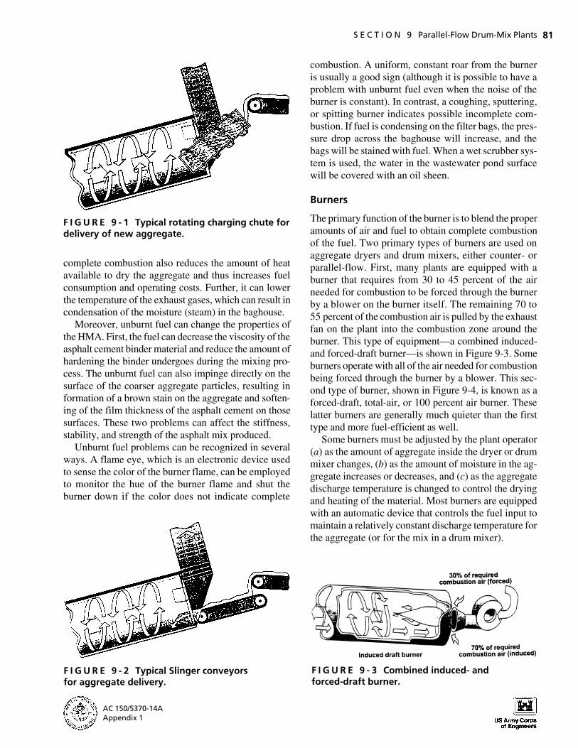
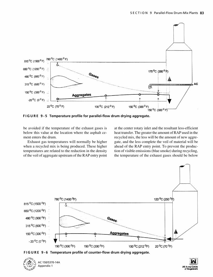
There are two ways to introduce new aggregate from the charging conveyor. The first is by means of a charging chute located above the burner. The aggregate is delivered into a sloped chute and slides by gravity into the drum. The chute is angled to push the aggregate away from direct contact with the burner flame and toward the rear of the drum. The aggregate can also be deposited on a Slinger conveyor belt located beneath the burner. On some plants, the speed of this conveyor can be changed so that the aggregate can be deposited farther down the drum, away from the burner flame. Figures 9-1 and 9-2 show a rotating feed and a Slinger conveyor, respectively, for a counter-flow drum.
BURNER SYSTEM
The burner heats and dries the aggregate. Burners are rated by a Uniform Burner Rating Method that is based
on eight criteria: (a) percent excess air, (b) percent leakage air, (c) percent casing (shell) loss, (d ) fan gas temperature, (e) percent moisture removed from the aggregate, ( f ) mix discharge temperature, (g) use of No. 2 fuel oil, and (h) specific heat of the aggregate. The maximum output for the burner under these conditions can be found on the rating plate attached to each burner, although the actual operating conditions for the burner may differ from those used to rate the burner.
Fuel
Most burners are designed to burn more than one type of fuel with only minor changes in the burner settings. Three types of fuel are used: gaseous, liquid, and solid. Gaseous fuels include both natural gas and liquid petroleum gas. Liquid fuels include propane, butane, No. 2 fuel oil, heavy fuel oil (Nos. 4 through 6), and reclaimed oil. Pulverized coal and pelletized biomass are examples of solid fuels.
The fuel selected should be at the proper consistency for complete atomization at the time of combustion. No. 2 fuel oil will burn at ambient temperatures, without preheating, because it has a viscosity below 100 saybolt seconds universal (SSU). For proper atomization, heavy fuel oil, such as Nos. 5 or 6, must be preheated before burning to reduce the viscosity below 100 SSU and thereby atomize the fuel properly for its complete combustion. Some reclaimed oil, which has been filtered and dewatered, burns well. Other reclaimed fuel, contaminated with heavy metals, hazardous waste, or water, burns erratically and incompletely and generally should not be used in an HMA plant burner. Incomplete combustion is not normally a problem when gaseous fuels are used.
Unburnt fuel can cause difficulty with the burner, the plant, and the mix, and is a waste of money as well. It can cause clogging of the burner nozzle, difficulties in lighting the burner, and increased maintenance costs. Incomplete combustion can result in unburnt fuel entering the emission-control equipment—coating and blinding the filter bags in a baghouse (increasing the opportunity for a baghouse fire) or covering the wastewater pond surface with fuel if a wet scrubber system is used. In-
AC 150/5370-14A Appendix 1
9727-09/Sec9 12/20/00 17:47 Page 81
F I G U R E 9 - 1 Typical rotating charging chute for delivery of new aggregate.
complete combustion also reduces the amount of heat available to dry the aggregate and thus increases fuel consumption and operating costs. Further, it can lower the temperature of the exhaust gases, which can result in condensation of the moisture (steam) in the baghouse.
Moreover, unburnt fuel can change the properties of the HMA. First, the fuel can decrease the viscosity of the asphalt cement binder material and reduce the amount of hardening the binder undergoes during the mixing process. The unburnt fuel can also impinge directly on the surface of the coarser aggregate particles, resulting in formation of a brown stain on the aggregate and softening of the film thickness of the asphalt cement on those surfaces. These two problems can affect the stiffness, stability, and strength of the asphalt mix produced.
Unburnt fuel problems can be recognized in several ways. A flame eye, which is an electronic device used to sense the color of the burner flame, can be employed to monitor the hue of the burner flame and shut the burner down if the color does not indicate complete
F I G U R E 9 - 2 Typical Slinger conveyors for aggregate delivery.
AC 150/5370-14A Appendix 1
S E C T I O N 9 Parallel-Flow Drum-Mix Plants 81
combustion. A uniform, constant roar from the burner is usually a good sign (although it is possible to have a problem with unburnt fuel even when the noise of the burner is constant). In contrast, a coughing, sputtering, or spitting burner indicates possible incomplete combustion. If fuel is condensing on the filter bags, the pressure drop across the baghouse will increase, and the bags will be stained with fuel. When a wet scrubber system is used, the water in the wastewater pond surface will be covered with an oil sheen.
Burners
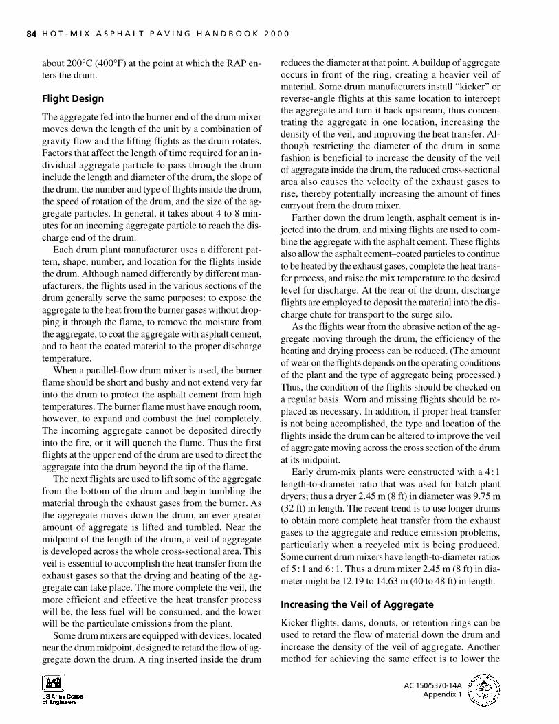
The primary function of the burner is to blend the proper amounts of air and fuel to obtain complete combustion of the fuel. Two primary types of burners are used on aggregate dryers and drum mixers, either counter- or parallel-flow. First, many plants are equipped with a burner that requires from 30 to 45 percent of the air needed for combustion to be forced through the burner by a blower on the burner itself. The remaining 70 to 55 percent of the combustion air is pulled by the exhaust fan on the plant into the combustion zone around the burner. This type of equipment—a combined induced-and forced-draft burner—is shown in Figure 9-3. Some burners operate with all of the air needed for combustion being forced through the burner by a blower. This second type of burner, shown in Figure 9-4, is known as a forced-draft, total-air, or 100 percent air burner. These latter burners are generally much quieter than the first type and more fuel-efficient as well.
Some burners must be adjusted by the plant operator (a) as the amount of aggregate inside the dryer or drum mixer changes, (b) as the amount of moisture in the aggregate increases or decreases, and (c) as the aggregate discharge temperature is changed to control the drying and heating of the material. Most burners are equipped with an automatic device that controls the fuel input to maintain a relatively constant discharge temperature for the aggregate (or for the mix in a drum mixer).
F I G U R E 9 - 3 Combined induced- and forced-draft burner.

9727-09/Sec9 12/20/00 17:47 Page 82
82 H O T - M I X A S P H A L T P A V I N G H A N D B O O K 2 0 0 0
F I G U R E 9 - 4 Forced-draft, total-air, or 100 percent burner.
A lack of either air or fuel will reduce the efficiency of the burner. Usually the availability of air is the limiting factor. The exhaust fan, besides providing the induced air, must also pull the moisture vapor (steam) created in the drying process and the products of combustion through the dryer or drum mixer. The capacity of this fan is a controlling factor in the heating and drying of the aggregate. The volume of the exhaust gases (air, moisture vapor, and combustion products) pulled by the fan is constant, depending on the setting of the damper in the system.
The efficiency of the system is also affected by air leaks. Because the fan pulls a constant volume of exhaust gases, at a constant damper setting, through the system from the burner and through the fan, any air that enters the system downstream of the burner reduces the amount of secondary air that can be pulled by the fan. Air leaks should be eliminated to provide the volume of air at the burner required to achieve complete combustion of the fuel. A damper, operated manually or automatically, should also be placed in the ductwork to control the amount of air entering the system.
HEAT TRANSFER PROCESS
Temperatures Inside the Drum
The temperature of the burner flame exceeds 1400°C (2,500°F). Exit gas temperatures for parallel-flow drum mixers are typically as much as 30°C (54°F) higher than exit mix temperatures. Exit gas temperatures higher than this could indicate improper flighting, and corrective actions should be taken. Typical temperature profiles for the exhaust gases and the aggregate along the length of the drum for parallel- and counter-flow drums are shown in Figures 9-5 and 9-6. The difference between the exhaust gas and mix discharge temperatures represents the efficiency of the heat transfer process and the amount of heat that is available to dry and heat the ag
gregate. Perfect heat transfer in a parallel-flow drum would require that the mix discharge and exhaust gas temperatures be equal at the point at which the mix is discharged from the plant.
Although a measure of the efficiency of the heat transfer process is obtained by comparing the mix discharge and exhaust gas temperatures at the time the gases exit the drum, it is often difficult to determine the temperature of the exhaust gases accurately at this location. The temperature differential is normally measured in the ductwork at a point between the end of the drum mixer and the entry of the exhaust gases into the emission-control equipment. This latter procedure is done by means of a thermocouple attached to the duct-work upstream of the point where the exhaust gases are drawn into the wet scrubber or baghouse system. For efficient operation of the drum mixer, the temperature of the exhaust gas before entry into the emission-control system should be within 10°C (20°F) of the mix discharge temperature.
It is generally not possible to compare the mix discharge temperature and the temperature of the exhaust gases at the point at which they exit the plant stack. If a wet scrubber is employed on the plant, the water used to impinge on the dust particles in the exhaust gases will naturally cool the gases. Moreover, for both wet scrubber and baghouse emission-control systems, any leakage air that is drawn into the ductwork and emission-control equipment between the end of the drum and the stack will reduce the temperature of the exhaust gases before they leave the stack. Thus the mix discharge and exhaust gas temperatures must be compared in the ductwork before the gases enter the emission-control equipment.
If the exhaust gas temperature in the ductwork is, say, 180°C (360°F) and the mix discharge temperature is 140°C (280°F), the veil of aggregate inside the drum is probably incomplete, and the drum is being operated inefficiently. Several problems result, including increased fuel use, possible separation of some of the very fine aggregate particles from the rest of the aggregate in the drum, and increased deterioration of the filter bags if a baghouse is used.
The temperature of the exhaust gases must also be controlled at the location where the asphalt cement is injected. Certain asphalt cements, depending on the source of the crude oil and the refining process used to produce the material, may contain small amounts of volatile material or “light ends” that can be driven off at temperatures as low as 330°C (600°F) and even much lower when moisture is present. Visible emissions can
AC 150/5370-14A Appendix 1
9727-09/Sec9 12/20/00 17:47 Page 83
S E C T I O N 9 Parallel-Flow Drum-Mix Plants 83
F I G U R E 9 - 5 Temperature profile for parallel-flow drum drying aggregate.
be avoided if the temperature of the exhaust gases is at the center rotary inlet and the resultant less-efficient below this value at the location where the asphalt ce- heat transfer. The greater the amount of RAP used in the ment enters the drum. recycled mix, the less will be the amount of new aggre-
Exhaust gas temperatures will normally be higher gate, and the less complete the veil of material will be when a recycled mix is being produced. These higher ahead of the RAP entry point. To prevent the productemperatures are related to the reduction in the density tion of visible emissions (blue smoke) during recycling, of the veil of aggregate upstream of the RAP entry point the temperature of the exhaust gases should be below
F I G U R E 9 - 6 Temperature profile of counter-flow drum drying aggregate.
AC 150/5370-14A Appendix 1
9727-09/Sec9 12/20/00 17:47 Page 84
84 H O T - M I X A S P H A L T P A V I N G H A N D B O O K 2 0 0 0
about 200°C (400°F) at the point at which the RAP enters the drum.
Flight Design
The aggregate fed into the burner end of the drum mixer moves down the length of the unit by a combination of gravity flow and the lifting flights as the drum rotates. Factors that affect the length of time required for an individual aggregate particle to pass through the drum include the length and diameter of the drum, the slope of the drum, the number and type of flights inside the drum, the speed of rotation of the drum, and the size of the aggregate particles. In general, it takes about 4 to 8 minutes for an incoming aggregate particle to reach the discharge end of the drum.
Each drum plant manufacturer uses a different pattern, shape, number, and location for the flights inside the drum. Although named differently by different manufacturers, the flights used in the various sections of the drum generally serve the same purposes: to expose the aggregate to the heat from the burner gases without dropping it through the flame, to remove the moisture from the aggregate, to coat the aggregate with asphalt cement, and to heat the coated material to the proper discharge temperature.
When a parallel-flow drum mixer is used, the burner flame should be short and bushy and not extend very far into the drum to protect the asphalt cement from high temperatures. The burner flame must have enough room, however, to expand and combust the fuel completely. The incoming aggregate cannot be deposited directly into the fire, or it will quench the flame. Thus the first flights at the upper end of the drum are used to direct the aggregate into the drum beyond the tip of the flame.
The next flights are used to lift some of the aggregate from the bottom of the drum and begin tumbling the material through the exhaust gases from the burner. As the aggregate moves down the drum, an ever greater amount of aggregate is lifted and tumbled. Near the midpoint of the length of the drum, a veil of aggregate is developed across the whole cross-sectional area. This veil is essential to accomplish the heat transfer from the exhaust gases so that the drying and heating of the aggregate can take place. The more complete the veil, the more efficient and effective the heat transfer process will be, the less fuel will be consumed, and the lower will be the particulate emissions from the plant.
Some drum mixers are equipped with devices, located near the drum midpoint, designed to retard the flow of aggregate down the drum. A ring inserted inside the drum
reduces the diameter at that point. A buildup of aggregate occurs in front of the ring, creating a heavier veil of material. Some drum manufacturers install “kicker” or reverse-angle flights at this same location to intercept the aggregate and turn it back upstream, thus concentrating the aggregate in one location, increasing the density of the veil, and improving the heat transfer. Although restricting the diameter of the drum in some fashion is beneficial to increase the density of the veil of aggregate inside the drum, the reduced cross-sectional area also causes the velocity of the exhaust gases to rise, thereby potentially increasing the amount of fines carryout from the drum mixer.
Farther down the drum length, asphalt cement is injected into the drum, and mixing flights are used to combine the aggregate with the asphalt cement. These flights also allow the asphalt cement–coated particles to continue to be heated by the exhaust gases, complete the heat transfer process, and raise the mix temperature to the desired level for discharge. At the rear of the drum, discharge flights are employed to deposit the material into the discharge chute for transport to the surge silo.
As the flights wear from the abrasive action of the aggregate moving through the drum, the efficiency of the heating and drying process can be reduced. (The amount of wear on the flights depends on the operating conditions of the plant and the type of aggregate being processed.) Thus, the condition of the flights should be checked on a regular basis. Worn and missing flights should be replaced as necessary. In addition, if proper heat transfer is not being accomplished, the type and location of the flights inside the drum can be altered to improve the veil of aggregate moving across the cross section of the drum at its midpoint.
Early drum-mix plants were constructed with a 4�1 length-to-diameter ratio that was used for batch plant dryers; thus a dryer 2.45 m (8 ft) in diameter was 9.75 m (32 ft) in length. The recent trend is to use longer drums to obtain more complete heat transfer from the exhaust gases to the aggregate and reduce emission problems, particularly when a recycled mix is being produced. Some current drum mixers have length-to-diameter ratios of 5�1 and 6�1. Thus a drum mixer 2.45 m (8 ft) in diameter might be 12.19 to 14.63 m (40 to 48 ft) in length.
Increasing the Veil of Aggregate
Kicker flights, dams, donuts, or retention rings can be used to retard the flow of material down the drum and increase the density of the veil of aggregate. Another method for achieving the same effect is to lower the
AC 150/5370-14A Appendix 1

9727-09/Sec9 12/20/00 17:47 Page 85
S E C T I O N 9 Parallel-Flow Drum-Mix Plants 85
slope of the drum. The reduction in slope (from a maximum of 6.0 percent to a minimum of 2.5 percent) increases the dwell or residence time of the aggregate in the drum and thus provides more time to complete the heat transfer process. The additional aggregate retained in the drum because of the lower slope also causes a denser veil of material across the drum cross section, further improving the degree of heat transfer.
Lowering the slope of the drum does not normally cause a change in the plant production rate. An individual aggregate particle takes longer to travel through the drum when the slope is decreased, but the actual production rate is unchanged in terms of tonnes (tons) per hour. Power requirements for the electric motors used to turn the drum are increased because of the extra weight of aggregate in the drum. The net result, however, is a better veil of aggregate, more complete heat transfer, and a reduction in the temperature of the exhaust gases at all locations in the drum.
Several manufacturers have developed drum mixers that change in diameter along their length: the drum is one diameter at one or both ends and a smaller diameter in the center. The change in diameter allows more room for combustion of the burner fuel and provides for development of a denser veil of aggregate in the drum by squeezing the same volume of material that was tumbling in a drum 2.60 m (8.2 ft) in diameter, for example, into a section 2.13 m (7 ft) in diameter, significantly increasing the density of the aggregate veil. In this case, the reduced diameter works in the same manner as the installation of a ring inside the drum. The heavier veil improves the efficiency of the heat transfer process. The velocity of the exhaust gases, however, also rises because of the smaller diameter, potentially increasing the amount of particulates carried out into the emission-control equipment and possibly reducing production levels as well.
Heat Transfer
While the exhaust gas temperature is being reduced as the gases move down the drum, the temperature of the aggregate is increasing as it travels in a parallel direction. The heat transfer process takes place in three ways: radiant, conductive, and convective. Radiant heat comes from the burner flame as aggregates pass under or over the flame. Conductive heat comes from contact with heated aggregate and the hot shell. Convective heat is transferred by the hot exhaust gases. The primary method of heat transfer is convective.
The aggregate enters the drum at ambient temperature, and radiant heat from the flame strikes the aggregate,
which immediately begins to dry and heat. As the material moves down the drum, its temperature is increased until it reaches a point upstream of the drum midpoint, where its temperature remains relatively constant because the heat from the exhaust gases is being used to evaporate the moisture in the aggregate. The amount of time the aggregate temperature remains constant depends in part on the amount of moisture in the incoming material. The porosity of the aggregate is also a factor. Moisture in porous material takes longer to be removed from the internal pores. Fine aggregate (sand) is typically heated more quickly and gets hotter than coarse aggregate because of its greater surface area per kilogram (pound).
Once most of the moisture has been removed, the aggregate temperature begins to rise again. After the asphalt cement is injected, mixing flights are used in most drum-mix plants to tumble the mix, partially exposing the material to the exhaust gases. The mix reaches the required discharge temperature as it approaches the end of the drum. In summary, the aggregate increases in temperature until drying begins, the temperature remains relatively constant until the aggregate is dried, and then the temperature increases again as the aggregate proceeds down the drum.
The moisture content of the aggregate decreases gradually in the front portion of the drum and then more rapidly as the aggregate reaches the temperature required to vaporize water. If the dwell time in the central portion of the drum is long enough, the moisture content of the mix at discharge can be reduced to less than 0.1 percent. The moisture content of the mix at discharge should almost always be less than 0.5 percent, and ideally less than 0.2 percent.
ASPHALT CEMENT INJECTION
On a very few old parallel-flow drum-mix plants, the asphalt cement supply line enters from the front of the drum, at the burner end. The diameter of the pipe used depends on the capacity of the plant, with a diameter of 50 to 100 mm (2 to 4 in.) being typical. The asphalt cement is not normally sprayed through a nozzle, but injected into the drum merely by flowing out of the end of the pipe. The actual point of discharge varies but tends to be between the midpoint and about two-thirds of the way down the drum length from the burner.
One advantage of early asphalt cement introduction is quick capture of the dust particles in the aggregate by the binder material. This action reduces the amount of particulate carryout by encapsulating the fines in the as-
AC 150/5370-14A Appendix 1
9727-09/Sec9 12/20/00 17:47 Page 86
86 H O T - M I X A S P H A L T P A V I N G H A N D B O O K 2 0 0 0
phalt cement. There are, however, three disadvantages: (a) the asphalt cement may be hardened more by exposure to the higher-temperature exhaust gases, (b) the production of blue smoke (visible stack emissions) from volatilization of the light ends from certain asphalt cements can be increased because of these higher exhaust gas temperatures, and (c) an increase in the moisture content of the mix at discharge may occur because the asphalt cement coats the aggregate particles before all the water in the material has been removed. These disadvantages of the system outweigh its advantages. Thus it is not good practice to inject the binder material near the burner end of the mixing drum.
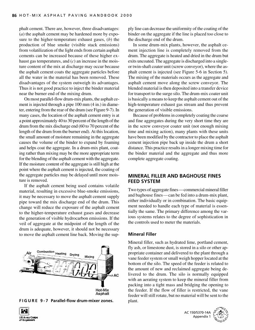
On most parallel-flow drum-mix plants, the asphalt cement is injected through a pipe 100 mm (4 in.) in diameter, entering from the rear of the drum (see Figure 9-7). In many cases, the location of the asphalt cement entry is at a point approximately 40 to 30 percent of the length of the drum from the mix discharge end (60 to 70 percent of the length of the drum from the burner end). At this location, the small amount of moisture remaining in the aggregate causes the volume of the binder to expand by foaming and helps coat the aggregate. In a drum-mix plant, coating rather than mixing may be the more appropriate term for the blending of the asphalt cement with the aggregate. If the moisture content of the aggregate is still high at the point where the asphalt cement is injected, the coating of the aggregate particles may be delayed until more moisture is removed.
If the asphalt cement being used contains volatile material, resulting in excessive blue-smoke emissions, it may be necessary to move the asphalt cement supply pipe toward the mix discharge end of the drum. This change will reduce the exposure of the asphalt cement to the higher-temperature exhaust gases and decrease the generation of visible hydrocarbon emissions. If the veil of aggregate at the midpoint of the length of the drum is adequate, however, it should not be necessary to move the asphalt cement line back. Moving the sup-
F I G U R E 9 - 7 Parallel-flow drum-mixer zones.
ply line can decrease the uniformity of the coating of the binder on the aggregate if the line is placed too close to the discharge end of the drum.
In some drum-mix plants, however, the asphalt cement injection line is completely removed from the drum. The aggregate is heated and dried in the drum but exits uncoated. The aggregate is discharged into a single-or twin-shaft coater unit (screw conveyor), where the asphalt cement is injected (see Figure 5-6 in Section 5). The mixing of the materials occurs as the aggregate and asphalt cement move along the screw conveyor. The blended material is then deposited into a transfer device for transport to the surge silo. The drum-mix coater unit is basically a means to keep the asphalt cement out of the high-temperature exhaust gas stream and thus prevent the generation of visible emissions.
Because of problems in completely coating the coarse and fine aggregates during the very short time they are in the screw conveyor coater unit (not enough mixing time and mixing action), many plants with these units have been modified by the contractor to place the asphalt cement injection pipe back up inside the drum a short distance. This practice results in a longer mixing time for the binder material and the aggregate and thus more complete aggregate coating.
MINERAL FILLER AND BAGHOUSE FINES FEED SYSTEM
Two types of aggregate fines—commercial mineral filler and baghouse fines—can be fed into a drum-mix plant, either individually or in combination. The basic equipment needed to handle each type of material is essentially the same. The primary difference among the various systems relates to the degree of sophistication in the controls used to meter the materials.
Mineral Filler
Mineral filler, such as hydrated lime, portland cement, fly ash, or limestone dust, is stored in a silo or other appropriate container and delivered to the plant through a vane feeder system or small weigh hopper located at the bottom of the silo. The speed of the feeder is related to the amount of new and reclaimed aggregate being delivered to the drum. The silo is normally equipped with an aerating system to keep the mineral filler from packing into a tight mass and bridging the opening to the feeder. If the flow of filler is restricted, the vane feeder will still rotate, but no material will be sent to the plant.
AC 150/5370-14A Appendix 1

9727-09/Sec9 12/20/00 17:48 Page 87
S E C T I O N 9 Parallel-Flow Drum-Mix Plants 87
The mineral filler can be delivered to the charging conveyor on the cold-feed system and delivered into the drum as part of the aggregate. This practice is not recommended, however. First, there is a problem of dusting of the filler material when it is deposited on the incoming aggregate. Second, the very fine filler has a tendency to become airborne easily inside the drum (picked up in the exhaust gas stream) and carried either to the discharge chute on the drum or into the emission-control equipment. Thus, some of the filler can be carried out of the drum mixer instead of being incorporated into the mix.
It is also possible to blend the mineral filler with the asphalt cement in the storage tank before the combined materials are fed into the plant. This is rarely done, however, because of problems of separation and settlement of the heavier mineral filler (higher specific gravity) from the lighter asphalt cement whenever plant production is interrupted.
The mineral filler from the vane feeder thus typically enters the delivery pipe and is conveyed pneumatically through the line and into the rear of the drum. The filler is discharged in one of two ways. It can be deposited from the line onto the aggregate at the bottom of the drum or fed into a mixing device, where the mineral filler and asphalt cement are mixed before being dropped into the drum.
If the mineral filler is discharged directly into the drum mixer, this can be done either upstream or downstream of the asphalt cement injection point. If the filler is discharged into the drum upstream of the asphalt cement entry point, it is usually dropped directly on the aggregate in the bottom of the drum because the filler is dry and of very small particle size. If lifted into the exhaust gas stream, a major portion of the material, depending
on drum operating conditions, may be carried out of the drum and into the emission-control equipment.
If the mineral filler is discharged from its feed pipe into the drum after the asphalt cement has been injected into the drum mixer, a greater portion of the filler is usually captured by the asphalt cement. The mineral filler has less chance of becoming airborne and being carried out of the drum. If the mineral filler and asphalt cement are blended in some form of mixing device as the asphalt cement is being introduced into the drum, minimal carryout of the filler material normally occurs.
Baghouse Fines
If a baghouse (fabric filter) is used as the emission-control equipment on the plant, either all or a portion of the material captured can be fed back into the drum mixer. The fines captured in the baghouse are carried, usually by a screw conveyor, through an air lock and then fed pneumatically through a pipe into the rear end of the drum, as seen in Figure 9-8.
The baghouse fines typically are not metered, but are returned on a continuous basis and discharged into the drum in a fashion similar to that of mineral filler. Occasionally a surge of fine material may be carried back to the drum mixer. If plant operating characteristics cause such surges of baghouse fines to occur regularly, the fines should be collected in a small surge silo and then metered back into the plant using a vane feeder system. If the baghouse fines are not needed to satisfy mix design requirements, they can be wasted instead of being returned to the mix.
The returned fines must be incorporated into the asphalt mixture and not allowed to recirculate back to the
F I G U R E 9 - 8 Pneumatic transfer to mixing area of drum.
AC 150/5370-14A Appendix 1
9727-09/Sec9 12/20/00 17:48 Page 88
88 H O T - M I X A S P H A L T P A V I N G H A N D B O O K 2 0 0 0
baghouse. This is accomplished by ensuring that the fines are kept out of direct contact with the high-velocity exhaust gases and are quickly coated with asphalt cement. If the fines are carried back to the baghouse, they will be caught and again returned to the drum mixer. Soon the baghouse will be overloaded with fines, because new fines are continually being generated inside the plant. The baghouse will become plugged and will not operate properly. It is therefore essential that, as with mineral filler, baghouse fines be coated with asphalt cement before being picked up by the exhaust gases and carried out of the mixer.
The amount and gradation of the baghouse fines returned to the asphalt mix inside the drum can have a significant effect on the properties of the mixture produced.
RECLAIMED ASPHALT PAVEMENT RECYCLING SYSTEMS
Single-Feed Systems
Because of inherent emission-control problems involved in using single-feed systems, split-feed systems, in which the RAP is fed to the drum mixer separately from the new aggregate, are used most commonly to produce recycled asphalt mixes. On the few remaining plants that use a single-feed system to deliver both the new aggregate and the RAP to the burner end of the drum mixer, several methods are used, alone or in combination, to protect the asphalt-coated material from direct contact with the flame and to reduce the generation of visible hydrocarbon emissions.
One method is to spray water on the combined aggregate on the charging conveyor before it enters the drum. The degree of protection offered by the additional water on the surface of the aggregate depends on the amount of moisture already in and on the reclaimed material, the amount of water applied (typically between 1 and 4 percent by weight of reclaimed aggregate), and the position of the reclaimed material on the charging conveyor— underneath or on top of the new aggregate.
Another method involves use of a heat shield to reduce the contact of the combined aggregate with the flame. This device spreads the flame out around the circumference of the drum and decreases the concentration of heat at any one point near the flame. The performance of the heat shield is dependent on its location inside the drum, the amount of RAP in the mix, the moisture content of new and reclaimed aggregate, and the required mix discharge temperature. The efficiency of the heat
shield can be determined by the amount of blue smoke that is generated during the recycling operation.
Split-Feed Systems
With a split-feed system, the new aggregate is delivered to the burner end of the drum-mix plant in a conventional manner. The RAP is delivered into a separate entry point near the midpoint of the drum length, as shown earlier in Figure 5-6.
A variety of designs are employed for the intake system used to introduce the RAP into the drum. Typically, the drum has a series of ports or entry chutes cut into the shell to allow the RAP to be introduced from the charging conveyor as the drum turns. At the point at which the RAP enters the shell, a short length of the flighting is often removed or configured so that the asphalt-coated material can easily be added to the new aggregate. The RAP begins heating as soon as it enters the port. The combined aggregate is picked up by the flights, and the heating and drying of the new material and the RAP continue.
When RAP is charged into the drum at its midpoint, less new aggregate is placed into the drum at the burner end, reducing the density of the veil of aggregate upstream of the RAP entry and decreasing the amount of heat transferred from the exhaust gases to the new aggregate. Thus the temperature of the gases at the point at which they come in contact with the RAP is higher, and there is a greater chance of burning off the asphalt coating on the RAP. This problem increases in severity as the amount of RAP used in the recycled mix increases and the amount of new aggregate decreases accordingly. Methods for reducing the exhaust gas temperature involve increasing the density of the veil of new aggregate upstream of the RAP entry location, as well as raising the temperature of the RAP before it comes into contact with the heated new aggregate.
Normally, if 20 percent or less RAP is being incorporated into a recycled mix and a split-feed system is used, minimal hydrocarbon emissions are produced, depending on the adequacy of the veil of new aggregate inside the drum and the discharge temperature of the mix. As the percentage of RAP rises and the moisture content of the RAP increases, there is a greater potential for emission problems. When the amount of RAP used exceeds 50 percent by weight of mix, the emission of blue smoke during the recycling process can become significant. A combination of procedures, outlined above, is needed to ensure adequate heat transfer from the exhaust
AC 150/5370-14A Appendix 1

9727-09/Sec9 12/20/00 17:48 Page 89
S E C T I O N 9 Parallel-Flow Drum-Mix Plants 89
gases to the new aggregate before those gases come in contact with the RAP.
Only under ideal and carefully controlled production conditions may it be possible to incorporate over 50 percent RAP in a recycled mix without a major problem with visible emissions. Because of the reduced production rates and emission-control problems that occur when high percentages of RAP are used in a recycled asphalt mix, it is normally good practice to limit the amount of reclaimed material processed through a split-feed drum-mix plant to approximately 50 percent of the total aggregate weight. In most cases, the amount of RAP actually used is much less than 50 percent of the total mix weight.
PRODUCTION RATES
HMA drum-mix plants are rated by the number of tonnes (tons) of mix that can be produced per hour. The production capacity is usually related to the incoming aggregate temperature, the mix discharge temperature, the specific heat of the aggregate, and an average aggregate moisture content removal of 5 percent for a plant operated at sea level. Plant capacities are also affected by a number of other variables, including drum diameter, fuel type, exhaust gas velocity, capacity of the exhaust fan, amount of excess air at the burner, estimated air leakage into the system, and atmospheric conditions. Aggregate gradation may be a factor with mixes containing a large percentage of coarse aggregate because such mixes are more difficult to heat uniformly than mixes incorporating a balance of coarse and fine aggregate particles.
One of the variables that has the greatest effect on the plant production rate is the average moisture content of the coarse and fine aggregates. The moisture content of
the fine aggregate is usually higher than that of the coarse aggregate. The average moisture content is thus a function of the amount of moisture in the coarse aggregate and its percentage in the mix, plus the amount of moisture in the fine aggregate and its percentage in the mix.
If, for example, 60 percent of the mix consists of coarse aggregate with 3.0 percent moisture and 40 percent of the mix is fine aggregate (with 8.0 percent moisture), the moisture content of the combined aggregate is 5.0 percent. If the fine aggregate moisture is reduced to 6.0 percent, the moisture in the cold feed entering the drum is reduced to 4.2 percent. As the average percentage of moisture in the aggregate increases, the production capacity of a drum mixer of a given diameter decreases. At a constant average incoming moisture content, the production rate increases as the drum diameter becomes larger. The theoretical relationship among average moisture content, drum diameter and length, and calculated drum-mix plant production rate [at a mix discharge temperature of 132°C (270°F)] is shown in Table 9-1 for different models of one particular make of plant, at a given volume of exhaust gas flow and set of operating conditions for each size of plant. Similar charts are available from manufacturers of other makes of drum mixers.
Table 9-1 indicates that at an average moisture content of 5 percent, a drum-mix plant having a diameter of 1.8 m (6 ft) has a theoretical production capacity of 143 tonnes (158 tons) of mix per hour. If a drum 2.44 m (8 ft) in diameter is used, the manufacturing rate increases to 276 tonnes (305 tons) of mix per hour. For a drum mixer 3.0 m (10 ft) in diameter, the capacity increases to 492 tonnes (541 tons) of mix per hour at 5 percent moisture removal.
As the moisture content in the aggregate decreases from 5 to 3 percent, the production rate for a drum mixer
T A B L E 9 - 1 Nominal Drum-Mix Capacities
Drum Diam. Capacity (Tons per Hour) for Surface Moisture Removed (%)
& Length (ft) 2 3 4 5 6 7 8 9 10
5 × 22 178 140 116 100 84 79 74 63 58 6 × 24 278 220 178 158 137 121 116 100 89 7 × 30 420 336 273 236 205 184 163 147 137 8 × 32 541 430 352 305 263 236 210 194 173 9 × 36 719 578 478 410 357 315 284 257 236 10 × 40 956 761 630 541 473 430 378 341 315 NOTE: Figures for each size of dryer are for asphalt concrete mix capacities. Examples of theeffects of moisture content on plant production rates are for one manufacturer’s drum-mixplants. 1 ft = 0.305 m; 1 ton = 0.907 tonne.SOURCE: Barber-Greene.
AC 150/5370-14A Appendix 1
9727-09/Sec9 12/20/00 17:48 Page 90
90 H O T - M I X A S P H A L T P A V I N G H A N D B O O K 2 0 0 0
that is 2.4 m (8 ft) in diameter increases from 276 tonnes (305 tons) per hour to 391 tonnes (430 tons) of mix per hour. If the aggregates have a higher moisture content (for example, 8 percent), a drum mixer of the same 2.4-m (8-ft) diameter can produce only 191 tonnes (210 tons) of asphalt mix per hour. Thus the average moisture content of the aggregate directly affects the capacity of a drum-mix plant.
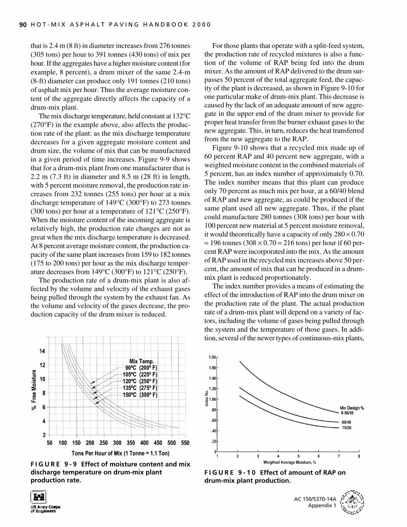
The mix discharge temperature, held constant at 132°C (270°F) in the example above, also affects the production rate of the plant: as the mix discharge temperature decreases for a given aggregate moisture content and drum size, the volume of mix that can be manufactured in a given period of time increases. Figure 9-9 shows that for a drum-mix plant from one manufacturer that is 2.2 m (7.3 ft) in diameter and 8.5 m (28 ft) in length, with 5 percent moisture removal, the production rate increases from 232 tonnes (255 tons) per hour at a mix discharge temperature of 149°C (300°F) to 273 tonnes (300 tons) per hour at a temperature of 121°C (250°F). When the moisture content of the incoming aggregate is relatively high, the production rate changes are not as great when the mix discharge temperature is decreased. At 8 percent average moisture content, the production capacity of the same plant increases from 159 to 182 tonnes (175 to 200 tons) per hour as the mix discharge temperature decreases from 149°C (300°F) to 121°C (250°F).
The production rate of a drum-mix plant is also affected by the volume and velocity of the exhaust gases being pulled through the system by the exhaust fan. As the volume and velocity of the gases decrease, the production capacity of the drum mixer is reduced.
F I G U R E 9 - 9 Effect of moisture content and mix discharge temperature on drum-mix plant production rate.
For those plants that operate with a split-feed system, the production rate of recycled mixtures is also a function of the volume of RAP being fed into the drum mixer. As the amount of RAP delivered to the drum surpasses 50 percent of the total aggregate feed, the capacity of the plant is decreased, as shown in Figure 9-10 for one particular make of drum-mix plant. This decrease is caused by the lack of an adequate amount of new aggregate in the upper end of the drum mixer to provide for proper heat transfer from the burner exhaust gases to the new aggregate. This, in turn, reduces the heat transferred from the new aggregate to the RAP.
Figure 9-10 shows that a recycled mix made up of 60 percent RAP and 40 percent new aggregate, with a weighted moisture content in the combined materials of 5 percent, has an index number of approximately 0.70. The index number means that this plant can produce only 70 percent as much mix per hour, at a 60/40 blend of RAP and new aggregate, as could be produced if the same plant used all new aggregate. Thus, if the plant could manufacture 280 tonnes (308 tons) per hour with 100 percent new material at 5 percent moisture removal, it would theoretically have a capacity of only 280 × 0.70 = 196 tonnes (308 × 0.70 = 216 tons) per hour if 60 percent RAP were incorporated into the mix. As the amount of RAP used in the recycled mix increases above 50 percent, the amount of mix that can be produced in a drum-mix plant is reduced proportionately.
The index number provides a means of estimating the effect of the introduction of RAP into the drum mixer on the production rate of the plant. The actual production rate of a drum-mix plant will depend on a variety of factors, including the volume of gases being pulled through the system and the temperature of those gases. In addition, several of the newer types of continuous-mix plants,
F I G U R E 9 - 1 0 Effect of amount of RAP on drum-mix plant production.
AC 150/5370-14A Appendix 1
9727-09/Sec9 12/20/00 17:48 Page 91
S E C T I O N 9 Parallel-Flow Drum-Mix Plants 91
such as the counter-flow drum mixers (see Section 10), are generally more efficient in heat transfer and thus can process amounts of RAP above 50 percent with less effect on the plant production rate.
PLANT EFFICIENCY
A plant should be operated at the most efficient production rate, irrespective of demand; it should be shut down when the silos are full and restarted when mix is needed once again. There are two methods of judging the efficiency of operation of a parallel-flow drum-mix plant: (a) determining the differential between the temperature of the mix upon discharge and that of the exhaust gases at the same point, and (b) observing the asphalt mixture as it is discharged.
Mix and Stack Temperatures
If perfect heat transfer could take place inside the drum, the temperature of the mix upon discharge from the parallel-flow drum-mix plant would be equal to the temperature of the exhaust gases at the same point (see also the earlier discussion of the heat transfer process). This equilibrium point would mean that the heat transfer was in balance and the drum mixer was running at maximum possible heat transfer efficiency. Under normal operating conditions, if the veil of aggregate inside the drum is complete, the exhaust gas temperature measured at the drum exit or before the gases enter the emission-control system should be within 10°C (18°F) of the temperature of the mix (assuming that no leakage occurs and no cooling air is added in the ductwork between the end of the drum and the point at which the gas temperatures are measured in the ductwork). Thus, if the mixture discharge temperature is 140°C (285°F), the measured exhaust gas temperature should be less than 150°C (300°F). This small temperature differential implies that the drum mixer is operating efficiently and that minimum fuel per tonne (ton) is being burned.
Exhaust gas temperature higher than about 10°C (18°F) above the mix temperature indicates that the heat transfer process inside the drum is not as efficient as it could be, primarily because of the lack of a uniformly dense veil of aggregate throughout the cross section of the drum. Temperature differentials of up to 55°C (98°F) between the mix and the exhaust gases are sometimes found, indicating that the plant is not being maintained or operated properly and that emission control might be a problem. The degree of operating inefficiency is related to the difference between the two temperatures (mix dis
charge and exhaust gas) before entry into the emission-control system.
During production of a recycled asphalt mixture in a single-feed drum mixer, the heat transfer between the exhaust gases and the new and reclaimed aggregates should be similar to that for a mixture using all new material. Thus for this process, the exhaust gas temperature should be within the 10°C (18°F) temperature differential if the plant is operating correctly. If a split-feed system is being employed, the difference between the two temperatures may be greater than 10°C (18°F), depending on the proportion of RAP introduced at the center inlet point. As a higher percentage of RAP is incorporated in the recycled mix, the temperature differential increases. When 50 percent of the recycled mix consists of RAP, the temperature of the exhaust gases may be more than 40°C (72°F) above the mix discharge temperature.
The efficiency of the heating and drying operation, therefore, can be judged in part by observing the temperature differential between the mix leaving the drum and the exhaust gases measured in the ductwork. Because both temperatures are usually recorded continuously and displayed on the plant control console, this method of monitoring the plant production process is easy to implement.
High exhaust gas temperatures can also lead to significant, premature corrosion on one side of the ductwork between the discharge end of the drum mixer and the primary collector. This corrosion is another reason why the efficiency of the plant operation needs to be monitored, and the temperature of the exhaust gases at the time they exit the drum mixer must be controlled.
Mix Discharge Monitoring
A second way to judge the efficiency of the drum-mix plant operation is to observe the asphalt mixture as it is discharged from the drum. The appearance of the mix, whether it consists of all new aggregate or a blend of new and reclaimed aggregate, should be uniform across the width of the discharge chute. The color of the aggregate particles should be consistent, and the finer aggregate particles should be evenly distributed throughout the mixture.
If the fuel used by the burner is not being completely combusted, the coarser aggregate particles in the mix may appear to be covered with a dark brown stain instead of with the proper film thickness of asphalt cement. In addition, the adhesion of the asphalt cement binder to the aggregate may be reduced, and the mix will have an increased tendency to strip when tested for potential moisture damage.
AC 150/5370-14A Appendix 1

9727-09/Sec9 12/20/00 17:48 Page 92
92 H O T - M I X A S P H A L T P A V I N G H A N D B O O K 2 0 0 0
If the veil of aggregate inside the drum is not complete, the exhaust gases will travel down one side of the drum, depending on which direction the drum is turning, at a higher velocity than on the other side of the drum. Fine dust-sized particles will be picked up in the exhaust gas stream and carried to the rear of the drum. As the exhaust gases change direction to enter the ductwork, the larger dust particles will drop out of the gas stream. These uncoated particles will be discharged on one side of the mixture as it exits the drum. A steady stream of light-brown, uncoated, fine aggregate particles on one side of the HMA discharge chute thus indicates that the veil of aggregate inside the drum is incomplete.
If a dry, powdered additive such as hydrated lime is being added to the incoming cold aggregate at the burner end of the mixer, it is possible for very fine material to be picked up in the exhaust gases shortly after it is charged into the plant. When the aggregate veil is proper, the fine material will be trapped in the tumbling mass of aggregate and incorporated into the mix. If the aggregate veil is incomplete, however, the powdered material may be carried down one side of the drum and then dropped into the bottom of the drum at the mix discharge point, depending on the size of the particles relative to the exhaust gas velocity. The powdered lime will then be visible on one side of the asphalt mixture as it is discharged from the drum. Thus this method of adding mineral filler should not be used unless that filler is well blended with the incoming aggregate before the two materials are charged into the drum mixer.
Typically, a high stack temperature relative to the mix discharge temperature will be accompanied by a stream of light-colored fines on one side of the mix discharge chute. Both of these phenomena are indications that the drum mixer is not operating efficiently. The plant operator should alter the production process to achieve a denser veil of aggregate in the drum.
SUMMARY
The following key factors should be considered when monitoring the operation of a parallel-flow drum-mix plant:
The sound of the burner should be monitored. A uniform, constant roar is desirable. A coughing, sputtering, or spitting sound may mean that the burner is not able to properly and completely combust the fuel it is trying to burn. Brown stains or a reduced asphalt cement film thickness on the coarser aggregate particles at the discharge end of the drum mixer also indicates problems with unburnt fuel.
The density of the veil of aggregate inside the drum near the midpoint of its length is the key to efficient operation of the drum mixer and economical fuel usage. The completeness of the veil can be determined from a comparison of the discharge temperature of the mix with that of the exhaust gases at the stack. The stack temperature should be no more than 10°C (18°F) higher than the mix discharge temperature if the veil of aggregate inside the drum is complete across the cross-sectional area of the drum (assuming that no cooling air is added in the emission-control system). Greater temperature differentials indicate that the plant is not being operated efficiently.
The presence of light-brown, uncoated fine aggregate on one side of the mix in the discharge chute is also an indication that the veil of aggregate is incomplete across the drum circumference.
The generation of visible hydrocarbon emissions from the stack further indicates that the temperature of the exhaust gases inside the drum is too high at the point where the asphalt cement is injected into the drum.
The density of the veil of aggregate inside the drum can be increased through the use of kicker flights, dams, donuts, or retention rings near the midpoint of the drum length. The density can also be increased by lowering the slope of the drum to increase the dwell or residence time of the aggregate in the drum.
Mineral filler or baghouse fines should be added through the mix discharge end of the drum. These materials should be coated with asphalt cement or captured in the mix before they are exposed to the exhaust gases moving down the drum.
If RAP is added to the drum through a split-feed system, the difference between the mix discharge temperature and the exhaust gas temperature measured at the stack will typically be greater than 10°C (18°F) and will usually increase roughly in proportion to the amount of RAP added to the mix.
The plant production rate is determined at a given mix discharge temperature and an average moisture content in the aggregate, usually 5 percent, at a given elevation (sea level). An increase in the moisture content or an increase in the mix discharge temperature will decrease the capacity of the drum mixer in terms of tonnes (tons) of mix produced per hour.
Production rates for recycled HMA, up to a RAP content of 50 percent, will normally be similar to the production rates for mixes containing all new aggregate. Above that amount of reclaimed material per ton of mix, the production rate of the parallel-flow drum mixer will decrease as the amount of reclaimed material increases.
AC 150/5370-14A Appendix 1
9727-10/Sec10 12/20/00 17:46 Page 93
S E C T I O N
10 Counter-Flow Drum-Mix Plants
In this section the processing of aggregate and asphalt cement inside a counter-flow drum-mix plant is addressed. This type of plant, developed in the early 1930s, has replaced the parallel-flow drum-mix plant in recent years as the primary type of plant purchased by contractors to manufacture HMA. The counter-flow drum-mix plant is essentially a counter-flow aggregate dryer similar to that used to heat and dry aggregate for a batch plant operation, with a mixing unit attached in one of two primary ways to the end of the dryer. The methods used to introduce the aggregate into the drum, the operation of the burner, and the heating and drying of the aggregate as it moves through the drum against the direction of the exhaust gases from the burner are reviewed first. The operation of the mixing unit is then described, including the introduction of the hot aggregate, the RAP, and the asphalt cement binder. The blending of the mix components is also reviewed. The section ends with a summary of the key factors that should be considered in monitoring the operation of a counter-flow drum-mix plant.
Two different types of counter-flow drum-mix plants are commonly marketed. The first, more conventional plant, shown earlier in Figure 5-7, has the mixing unit extended on the end of the aggregate dryer portion of the drum. The second type, a double-barrel plant shown in Figure 5-8, has the mixing unit folded back around the aggregate dryer portion of the drum. Both styles of plant accomplish the same processes—heating and drying the aggregate; adding mineral filler, baghouse fines, and RAP, as needed; adding the asphalt cement binder material; and mixing all of the components together to produce a high-quality HMA product.
AGGREGATE ENTRY, HEATING, AND DRYING
The aggregate enters the counter-flow drum-mix plant from the upper end of the drum, similar to the entry used for a batch plant dryer as discussed in Section 8. The aggregate normally is delivered into a sloped chute by the charging conveyor and slides by gravity into the drum. A Slinger conveyor system may be used to feed the ag
gregate into the drum. On some plants, a rotating chute is employed to ensure that the aggregate does not hang up during introduction into the drum.
On the conventional counter-flow drum-mix plant with the mixing unit extended behind the aggregate dryer portion of the drum (Figure 5-7), the burner head is embedded into the rotating drum. Although the burner itself is located outside the drum, the burner fuel does not ignite and burn until it reaches the burner head. All the air needed to combust the fuel is delivered through the burner. Additional air is drawn into the drum by the exhaust fan through a tube that surrounds the burner assembly and protects the burner from damage by the aggregate. Figure 5-7 shows the burner head as the aggregate moves downstream toward the burner, with the exhaust gases moving in the opposite direction.
On the double-barrel type of counter-flow drum mixer, the burner location is similar to that on a normal counter-flow aggregate dryer. The burner is a total-air burner, as discussed in Section 9 and shown in Figure 9-4. The position of the burner on this type of plant is seen in Figure 5-8.
The heating and drying of the aggregate are accomplished as the combined coarse and fine aggregate material moves through the dryer by the action of the rotating flights and gravity. The burner is located at the lower or discharge end of the drying unit, and the aggregate moves toward the burner as it travels through the drum. The exhaust gases from the burner move upstream, in the opposite direction to the flow of the aggregate. As the aggregate moves toward the burner and continues to heat, the moisture is removed from the surface of the aggregate particles. The internal moisture in the aggregate pieces is driven out, and the heating of the aggregate continues until the required aggregate discharge temperature is obtained.
If RAP is to be added to the new aggregate, the temperature of the new aggregate is increased to the level necessary to permit adequate heat transfer between the superheated new aggregate and the ambient-temperature reclaimed material. This practice is similar to the additional heating of the new aggregate when RAP is to be used in a batch plant mixing process (see Section 8).
AC 150/5370-14A Appendix 1
9727-10/Sec10 12/20/00 17:46 Page 94
94 H O T - M I X A S P H A L T P A V I N G H A N D B O O K 2 0 0 0
In contrast with a parallel-flow drum-mix plant, no asphalt cement binder material is added inside the drying portion of the counter-flow drum mixer. The initial section of the drum is a dryer only. No material—mineral filler, baghouse fines, or RAP—is added upstream of the burner.
MIXING UNIT
Conventional Counter-Flow Drum
For the counter-flow unit in which the burner is embedded into the drum and the mixing occurs as an extension of the operation of the drying drum, the heated and dried aggregate passes over a dam or retention ring located just behind (downstream of) the burner head. A series of openings or ports is typically used to permit the aggregate to pass into the mixing unit.
Once the heated aggregate has entered the mixing chamber of the drum, the RAP, if used, is added to the new aggregate. Because the RAP is introduced into the drum behind the burner, it is not exposed to the burner flame. For this reason, hydrocarbon emissions are not a problem, as they can be with a parallel-flow drum mixer. Heat transfer from the new aggregate begins as soon as the two materials come together at the upper end of the mixing unit. Moisture contained in the RAP is pulled out of the mixing unit and around the burner by the exhaust fan. Any hydrocarbon emissions released from the RAP are also pulled out of the mixing unit by the exhaust fan, but these fumes are incinerated as they pass through the burner area. Thus with a counter-flow drum mixer, the generation of blue smoke is minimized.
Shortly after the RAP has been introduced into the mixing portion of the drum, any other additives needed in the HMA, including baghouse dust and mineral filler, are also introduced. Because the air flow in the mixing unit is minimal, there is no chance for any relatively heavy powdered additive, such as the returned fines or filler, to become airborne and be drawn into the drying portion of the drum by the exhaust fan. Mixing of the RAP, filler and baghouse fines, and new aggregate begins as soon as the materials are introduced into the mixing chamber.
Very soon after all of the aggregate materials have been initially blended together, the binder is added to produce the HMA. The coating of the aggregate takes place as the combined materials are tumbled together and move toward the discharge end of the unit. Depending on the angle of the drum, as well as the number and type of flights in the mixing chamber, the mixing time in this type of counter-flow drum is typically
in the range of 45 to 60 seconds. On completion of the mixing process, the HMA material is delivered into a discharge chute and transported to a silo.
Double-Barrel Counter-Flow Drum
With a double-barrel system, the mixing chamber is folded back around the aggregate drying drum. This mixing unit is unusual because it does not rotate. As seen in Figure 5-8, the heated and dried aggregate is discharged from underneath the burner downward into the nonrotating outer shell or drum. This occurs at the lower end of the mixing unit.
Shortly after the new aggregate enters the mixing chamber, RAP, if used, is added to the external drum. This material falls into the shell and quickly blends with the superheated new aggregate. Heat transfer from the hot new aggregate to the ambient-temperature RAP begins immediately. As with the conventional counter-flow drum mixer, any moisture in the RAP and any hydrocarbon emissions that develop during the heating process are drawn back into the dryer unit by the exhaust fan. The moisture is carried into the emission-control equipment, similar to what happens with the moisture released by the new aggregate during the heating and drying process. The hydrocarbon emissions from the RAP, if any, are incinerated by the burner.
Once the RAP has entered the outer shell, any additives, such as mineral filler, needed in the mix are deposited into the mixing area. The baghouse fines are also introduced into the outer shell at the same location. Because the flow of air in the area between the inner drum and the outer shell is minimal, there is no tendency for the added materials to be pulled out of the mixing chamber and into the aggregate dryer section of the drum-mix plant.
When all of the aggregate materials are in the outer shell, the asphalt cement is added to the mix. On most double-barrel plants, the binder materials can be added in one of two different locations. If RAP is not added to the mix, the asphalt cement is most often introduced as quickly as possible—shortly after the new aggregate, baghouse fines, and mineral filler, if any, have been charged into the exterior drum. If RAP is used in the mix, the addition of the binder material is delayed so some heat transfer can take place between the superheated new aggregate and the reclaimed material. The new binder material enters the outer shell slightly farther downstream (but uphill).
Mixing takes place by a series of paddles attached to the outside of the inner drum—the aggregate dryer (see
AC 150/5370-14A Appendix 1
9727-10/Sec10 12/20/00 17:46 Page 95
S E C T I O N 1 0 Counter-Flow Drum-Mix Plants 95
Figure 5-8). The paddles are set at the proper angle to push the combination of new aggregate, baghouse fines and mineral filler, RAP, and asphalt cement uphill, blending these materials together as they travel in the narrow space between the outside of the rotating inner drum and the inside of the nonrotating outer drum. Mixing occurs only in a lower quarter-portion of the circumference of the outer shell; the mix is not carried over the top of the inner drum. In addition to the heat transfer that takes place by direct contact between the new aggregate and the other mix components, further heating occurs as all the materials come in contact with the inner drum and by radiation of heat from the inner drum into the outer shell.
To achieve efficient mixing, the appropriate distance between the ends of the paddles and the inside of the outer shell must be maintained. The paddle tips and liner plate of the outer shell must be checked for wear periodically to ensure that material is not building up on the outer shell and that adequate mixing is occurring. Depending on the size and production capacity of the double-barrel plant, blending of all of the mix components typically occurs in less than 60 seconds. Upon completion of the mixing process, the HMA material is delivered into a discharge chute for transport to a silo.
SUMMARY
The following key factors should be considered when monitoring the operation of a counter-flow drum-mix plant:
The new aggregate should be introduced into the upper end of the counter-flow dryer without obstruction. An inclined or rotating chute can be used for this purpose.
The RAP is introduced into the mixing unit behind the burner for a conventional counter-flow drum-mix plant and under the burner into the outer shell for a double-barrel plant.
In general, the RAP should enter the mixing unit before the mineral filler and baghouse fines are introduced into the mixing chamber.
The asphalt cement should be charged into the mixing unit after some heat transfer has taken place between the superheated new aggregate and the RAP. If mineral filler or baghouse fines are also being added to the mix, the binder material should be injected into the mixing area after the additives have entered.
The HMA mix being discharged from the mixing unit should be sampled to ensure that the mix components are completely mixed and adequately coated with asphalt cement.
AC 150/5370-14A Appendix 1
9727-11/Sec11 12/20/00 17:46 Page 96
S E C T I O N
Surge and Storage Silos and11 Truck-Loading Techniques
The primary purpose of a silo on a batch plant is to allow the plant to continue to produce material when trucks are not available to accept mix directly from the pugmill. For a drum-mix plant (either parallel-flow or counter-flow) operation, the main purpose of the silo is to convert a continuous mixing operation into a discontinuous or batch-type truck-loading process and to hold the mix temporarily until the next transport vehicle is available. In this section the types of silos and silo designs, as well as mix loading and unloading operations, are described. The emphasis throughout is on measures taken to prevent segregation, defined as the separation of the coarsest aggregate particles in the mix from the rest of the mix. The section ends with a summary of key factors that should be considered in monitoring silo and truck-loading operations.
TYPES OF SILOS AND SILO DESIGNS
Surge Versus Storage Silos
During the normal daily operation of an HMA plant, a silo can be used to store asphalt mix between the arrivals of trucks at the plant. In this case, the silo is typically termed a surge silo. If the silo is to be used to hold the mix for longer periods of time (several hours or more), it may be termed a storage silo. A storage silo can easily be used as a surge silo, but a surge silo may not be suitable for use as a storage silo.
There are several differences between the two types of silos. First, the capacity of a storage silo is typically greater than that of a surge silo. Second, a surge silo is usually insulated but not heated, whereas a silo used for mix storage is always well insulated and usually heated, either completely or partially. Third, the gates at the bottom of a storage silo are heated and sealed when mix is to be held for a long period of time; this is done to reduce the amount of air that can pass up into the mix through the gates. The bottom of a surge silo, on the other hand, is not normally heated or sealed.
The primary operation of both types of silos, however, is similar. Only the ability to store quantities of mix for longer time periods without significant changes
in the mix properties differentiates the two types. Regardless of the type of silo used, the mix that is held in the silo and then delivered to the haul truck should meet the same specifications and requirements as that discharged directly from the pugmill on a batch plant or from the discharge end of the drum mixer before passage into and out of the silo.
Insulation and Heat
As noted, most surge silos are insulated; this is done to reduce the loss of heat from the mix as it resides temporarily in the silo. The type of insulating material used and its thickness vary among silo manufacturers.
The cone at the base of a surge silo is usually heated to prevent the mix from sticking to the wall of the cone and building up. The heat can be provided by an electrical or hot-oil system. In some cases, the vertical walls of the silo are also heated so that the mix can retain its desired temperature for an extended period of time. If the silo is to be used strictly as a surge silo and is emptied of mix at the end of each production day, heating of the silo walls is usually unnecessary.
Storage
If an asphalt mixture must be retained in the silo overnight or over a weekend, this can usually be accomplished quite successfully without undue hardening or temperature loss in the mix. A well-insulated silo is required, but heating of the vertical silo walls is generally unnecessary. Mixes stored for several days in silos equipped with heated cones have shown only minimal oxidation and temperature loss. The amount of hardening that occurs is related to the amount of mix in the silo. The large mass of mix in a full silo will age less than will a small volume of mix in a nearly empty silo. The amount of temperature loss in the stored mix will depend on a number of other factors as well, including the initial mix temperature, the gradation of the material, and environmental conditions.
Asphalt mix (except mixtures with high coarse aggregate content, including friction course, stone-matrix asphalt, and coarse-graded Superpave mixes) may be stored for as long as a week when kept in a heated, air-
AC 150/5370-14A Appendix 1
9727-11/Sec11 12/20/00 17:46 Page 97
S E C T I O N 1 1 Surge and Storage Silos and Truck-Loading Techniques 97
tight silo. An inert gas system can be used to purge the silo of oxygen, but this is rarely done. The gates at the bottom of the silo, as well as any openings at the top of the silo, must be well sealed, however, to prevent the movement of air into and through the mix. The silo must also be completely heated and very well insulated. Mixes with high coarse aggregate content may tend to experience draindown if stored for an extended period of time.
If mix is to be stored in a silo for more than 2 or 3 days, such as over a long weekend or because of inclement weather conditions, it is advisable to remove a small amount of mix [at least 2 to 3 tonnes (2 to 3 tons) of material] from the silo every day or every other day during the storage period to ensure that the mix at the bottom of the cone does not set up and become impossible to discharge. If the mix is left undisturbed for a number of days, a plug of cold mix may form. When the discharge gates are finally opened, nothing happens—the mix has set up and will not flow out of the silo. The small amount of mix that is removed from the silo can be placed on the RAP pile for later recycling.
Although mix can be stored for relatively long periods of time, it is rarely necessary to do so with a continuously operating plant. Most silos, therefore, are used either as surge silos or periodically for overnight storage of the asphalt material. Mix held for more than 2 or 3 days in a silo should be tested to ensure that it meets all the same specifications and requirements as mix delivered directly to the paving site. This testing should include measurement of the mix temperature upon discharge from the silo and the properties of the asphalt cement recovered from the mix. As long as the mixture meets specifications, the length of time for which material is held in the silo should not be restricted. Such restriction increases the cost of the mix and reduces the efficiency of the mix production.
If an open-graded mixture is being stored temporarily, however, care must be taken to keep the mix storage temperature low enough so that the asphalt cement does not flow off of the aggregate (drain down) and collect at the bottom of the silo at the discharge gates. In general, it is not advisable to store an open-graded HMA mix overnight.
Conveying Devices
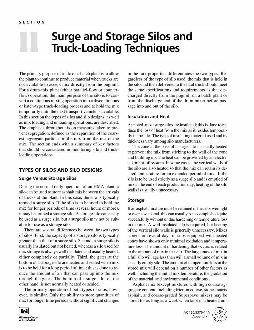
A variety of conveying devices are used to carry the HMA from the discharge chute on the drum mixer or the hopper under the pugmill of a batch plant to the silo. The equipment most commonly used is the drag slat conveyor, shown in Figures 11-1 and 11-2. In this sys-
F I G U R E 1 1 - 1 Slat conveyor feeding silos at an HMA plant.
tem, a continuous set of flights connected by a drag chain pulls the mix up an inclined metal chute. The amount of mix that can be carried by the drag slats depends on the spacing between the slats, the depth of the individual flights, the width of the flights, and the slope of the conveyor, as well as the size and speed of the drag chain and the power of the drive motor. On some drag slat conveyors, the speed of the conveyor can be altered to change the capacity of the device to better match the output of the plant.
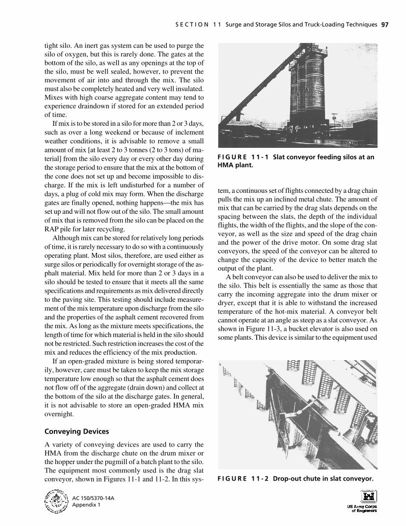
A belt conveyor can also be used to deliver the mix to the silo. This belt is essentially the same as those that carry the incoming aggregate into the drum mixer or dryer, except that it is able to withstand the increased temperature of the hot-mix material. A conveyor belt cannot operate at an angle as steep as a slat conveyor. As shown in Figure 11-3, a bucket elevator is also used on some plants. This device is similar to the equipment used
F I G U R E 1 1 - 2 Drop-out chute in slat conveyor.
AC 150/5370-14A Appendix 1
9727-11/Sec11 12/20/00 17:46 Page 98
98 H O T - M I X A S P H A L T P A V I N G H A N D B O O K 2 0 0 0
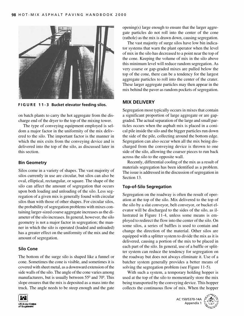
F I G U R E 1 1 - 3 Bucket elevator feeding silos.
on batch plants to carry the hot aggregate from the discharge end of the dryer to the top of the mixing tower.
The type of conveying equipment employed is seldom a major factor in the uniformity of the mix delivered to the silo. The important factor is the manner in which the mix exits from the conveying device and is delivered into the top of the silo, as discussed later in this section.
Bin Geometry
Silos come in a variety of shapes. The vast majority of silos currently in use are circular, but silos can also be oval, elliptical, rectangular, or square. The shape of the silo can affect the amount of segregation that occurs upon both loading and unloading of the silo. Less segregation of a given mix is generally found with circular silos than with those of other shapes. For circular silos, the probability of segregation problems with mixes containing larger-sized coarse aggregate increases as the diameter of the silo increases. In general, however, the silo geometry is not a major factor in segregation; the manner in which the silo is operated (loaded and unloaded) has a greater effect on the uniformity of the mix and the amount of segregation.
Silo Cone
The bottom of the surge silo is shaped like a funnel or cone. Sometimes the cone is visible, and sometimes it is covered with sheet metal, as a downward extension of the side walls of the silo. The angle of the cone varies among manufacturers, but is usually between 550 and 700. This slope ensures that the mix is deposited as a mass into the truck. The angle needs to be steep enough and the gate
opening(s) large enough to ensure that the larger aggregate particles do not roll into the center of the cone (rathole) as the mix is drawn down, causing segregation.
The vast majority of surge silos have low bin indicator systems that warn the plant operator when the level of mix in the silo has decreased to a point near the top of the cone. Keeping the volume of mix in the silo above this minimum level will reduce random segregation. As very coarse or gap-graded mixes are pulled below the top of the cone, there can be a tendency for the largest aggregate particles to roll into the center of the crater. These larger aggregate particles may then appear in the mix behind the paver as random pockets of segregation.
MIX DELIVERY
Segregation most typically occurs in mixes that contain a significant proportion of large aggregate or are gap-graded. The actual separation of the large and small particles occurs when the asphalt mix is placed in a conical pile inside the silo and the bigger particles run down the side of the pile, collecting around the bottom edge. Segregation can also occur when all the mix being discharged from the conveying device is thrown to one side of the silo, allowing the coarser pieces to run back across the silo to the opposite wall.
Recently, differential cooling of the mix as a result of materials segregation has been identified as a problem. The issue is addressed in the discussion of segregation in Section 13.
Top-of-Silo Segregation
Segregation on the roadway is often the result of operation at the top of the silo. Mix delivered to the top of the silo by a slat conveyor, belt conveyor, or bucket elevator will be discharged to the sides of the silo, as illustrated in Figure 11-4, unless some means is employed to redirect the flow into the center of the silo. On some silos, a series of baffles is used to contain and change the direction of the material. Other silos are equipped with a splitter system to divide the mix as it is delivered, causing a portion of the mix to be placed in each part of the silo. In general, use of a baffle or splitter system can reduce the tendency for segregation on the roadway but does not always eliminate it. Use of a batcher system generally provides a better means of solving the segregation problem (see Figure 11-5).
With such a system, a temporary holding hopper is used at the top of the silo to momentarily store the mix being transported by the conveying device. This hopper collects the continuous flow of mix. When the hopper
AC 150/5370-14A Appendix 1

9727-11/Sec11 12/20/00 17:46 Page 99
S E C T I O N 1 1 Surge and Storage Silos and Truck-Loading Techniques 99
F I G U R E 1 1 - 4 Segregation at top of silo without batcher.
is nearly full and the hopper gates are opened, the mix is deposited into the silo in a mass. The mass of mix hits the bottom of the empty silo or the top of mix already in the silo. Upon contact, the mix disperses in all directions uniformly, minimizing segregation. Moving HMA in a mass will always minimize segregation.
F I G U R E 1 1 - 5 Use of batcher to prevent top-of-silo segregation.
The batcher system functions well unless the silo is almost full. In the latter case, the mix does not fall very far when released from the hopper. When the falling mix hits the mix already in the silo beneath the hopper, it lacks the momentum to spread out over the area of the silo and forms a conical-shaped pile instead. This pile can be the beginning of a segregation problem as more mix is deposited on top of it. Most silos are therefore equipped with high silo indicator warning systems that alert the plant operator to cut off the flow of incoming mix when the silo becomes too full.
The batcher may not prevent a segregation problem if the mix is delivered improperly. In some cases, the transporting device places the mix all on one side of the hopper, as shown in Figure 11-6. This practice causes rolling of the coarse aggregate in the batcher itself. It also causes the mix to be dropped into the silo off center. Thus to prevent segregation of mixes containing a large portion of coarser aggregate, the mix must be deposited uniformly into the center of the hopper and delivered from the batcher into the center of the silo.
The batcher is typically equipped with a timing device that opens the discharge gates at the bottom of the silo on a regular basis. The amount of time between drops can be altered to match the production rate of the plant. If properly set, the timer will open the gates before the batcher is too full and will close the gates before the batcher is completely empty. This allows the conveying device to operate continuously while preventing discharge from the conveyor directly into the silo through the open batcher gates.
If the timer operates improperly, too much mix will be delivered into the batcher before the discharge gates are opened. If this occurs, the HMA material may overflow the batcher and back up into the conveying device. The conveyor will quickly become overloaded and then stop functioning. The plant will, in turn, have to cease
F I G U R E 1 1 - 6 Segregation caused by feeding batcher off center.
AC 150/5370-14A Appendix 1
9727-11/Sec11 12/20/00 17:46 Page 100
100 H O T - M I X A S P H A L T P A V I N G H A N D B O O K 2 0 0 0
production to prevent this problem, particularly if the timing device is not functioning properly. The plant operator may improperly leave the gates on the bottom of the batcher wide open. Doing so defeats the purpose of the batcher and allows the mix to dribble into the silo in a continuous stream, just as if the batcher were not there.
In other cases, the batcher may be emptied more often than is necessary—when only partially full. Such continual dumping of the hopper reduces the mass of material dropped into the silo at one time and increases the opportunity for formation of a conical pile of mix. The timer device should be set so that the gates of the batcher are closed before the batcher is empty. This practice will ensure that all the mix falls in a mass and will minimize segregation.
The capacity of the batcher at the top of the silo is related to the production capacity of the plant and is usually in the range of 2 to 5 tonnes (2 to 5 tons). A typical haul truck can hold from 14 to 20 tonnes (15 to 22 tons). Thus, depending on the capacity of both the batcher and each haul truck, it will take 3 to 11 batcher drops of mix to make up a full load in the haul truck.
Longitudinal (Side-to-Side) Segregation
Longitudinal (side-to-side) segregation will occur on one side of the lane being paved if the coarser aggregate particles are allowed to roll to one side of the silo. Depending on how the mix is delivered into the silo from the conveying device, the coarsest aggregate particles in the mix may collect on the opposite or the same side of the silo as the conveyor. In either case, those coarse aggregate particles will travel down one side of the silo and end up on one side of the haul truck and thus on one side of the laydown machine.
Longitudinal segregation will normally be found on only one side of the paver. In most cases, it will be relatively continuous on that side of the laydown machine if the plant is operated in a consistent manner. An easy way to determine the cause of this type of segregation is to reverse the direction in which the haul truck is being loaded underneath the silo and see whether the longitudinal segregation changes sides at the paver. If, for example, the longitudinal segregation is seen on the left-hand side of the paver lane and the haul truck is being loaded under the silo in its normal direction, the loading direction for the truck should be reversed. When the mix is subsequently delivered into the paver hopper— either directly from the haul truck or by means of a windrow and pickup machine—the longitudinal segregation should occur on the opposite side (the right side
in this example) of the paver lane. If the position of the longitudinal segregation changes sides at the paver when the direction of the truck loading is reversed, the cause of the side-to-side segregation is in the loading of the mix into the silo from the conveying device. The direction of the mix entering the silo at the top of the silo must then be changed so that the mix is deposited directly into the center of the silo and not permitted to roll to one side or the other.
LOADING OF TRUCKS FROM SILOS
Just as it is important to deliver mix in a mass into the center of the silo in order to avoid causing longitudinal segregation, it is important to deposit the asphalt mix in a mass into multiple locations in the bed of the haul truck in order to avoid truckload-to-truckload (or end-of-load) segregation.
Most silos have only one discharge opening, equipped with a single or double gates. The gates on the bottom of the cone should be opened quickly and completely so that the flow of mix begins immediately and is unrestricted. Once the proper weight has been discharged into the truck bed, the gates should be closed quickly. For silos equipped with double (clamshell-type) gates, closing of the gates generally does not create any problems. For silos equipped with a single gate, however, it is possible for the mix to be thrown to one side of the truck bed as the gate is closed. To minimize this problem, it is important to close the single gate as quickly as possible.
Some silos are equipped with two separate discharge openings. These silos distribute the mix over a greater length of the truck bed and thereby reduce the amount of segregation that may occur. The silo gates may be parallel or perpendicular to the direction of the truck. Both systems can deliver mix into the haul vehicle without segregation as long as the correct amount of mix is placed into the right position in the truck bed.
Segregation can be eliminated by moving the HMA in a mass and by reducing the distance that the coarse aggregate can roll. Multiple discharges of mix into the haul vehicle are very beneficial in keeping the mix uniform and in reducing the amount of segregation. Some plants are equipped with automatic silo discharge systems. The number of each truck is entered into the computer system, and that truck is loaded at predetermined intervals with preselected amounts of mix for each drop. With a manual system, the silo discharge operator should be able to determine the time it takes to deliver the proper amount of mix, per drop, into each haul vehicle. This
AC 150/5370-14A Appendix 1
9727-11/Sec11 12/20/00 17:46 Page 101
S E C T I O N 1 1 Surge and Storage Silos and Truck-Loading Techniques 101
can be done by timing the discharge of the mix and comparing that time with the weight of mix delivered. Because trucks come in a variety of sizes, the time per drop and the number of drops per truck may differ from truck to truck. With practice, however, the operator should be able to judge accurately the time needed to place the proper amount of material in each truck bed. This amount can be confirmed visually by watching the height of the growing pile of mix in the truck as the loading continues. Specific loading practices for the different types of haul trucks—end-dump, belly- or bottom-dump, and live-bottom—are described later in this section.
The operator should not be allowed to “top off” or dribble mix into the haul vehicle. The gates on the silo should not be opened and closed continually to deliver only small amounts of mix to the truck. This practice occurs most frequently in plants where the surge silos are placed directly over the truck scales. Because the operator can quickly determine the amount of mix actually in the truck bed by observing the scale readout on the control console, the tendency is to load the vehicle up to the legal limit by using multiple drops of small quantities of mix at the end of the main delivery. This topping-off process causes the coarsest aggregate particles in the mix to roll down the slope of the mix in the truck bed toward both the front and back of the truck, significantly contributing to segregation of the mix. If the discharge of mix from the silo is timed, however, this procedure is unnecessary, and the potential for mix segregation is reduced accordingly.
Some silos have a loading hopper or batcher under the cone. In many cases, this hopper is supported on load cells to measure the amount of mix being delivered from the silo into the haul vehicle. The mix from such a hopper or batcher must still be deposited into different sections of the truck bed in order to minimize segregation by reducing the distance that the coarsest aggregate particles can roll. It is important to determine the size of the batch being loaded into the truck from the hopper versus the amount of mix needed in each portion of the truck bed. Depending on the capacity of the hopper and the size of each truck, multiple batches may be needed at each loading location. The hopper should not be used to top off drops of mix already in the truck bed.
End-Dump Trucks
If the mix is deposited into the center of an end-dump truck bed, the material will build up into a conical pile. Because the growth of the pile will be restricted by the
sides of the truck, the larger aggregate particles will roll toward both the front and the back of the truck bed. In most cases, because of truckload weight laws and the amount of HMA that can be carried legally on the back axles, the mix is actually deposited into the truck bed to the front of the center of the length of the bed. This practice reduces the distance that the coarse aggregate particles can roll to the front of the bed but increases the distance that they can roll toward the tailgate.
The coarse aggregate pieces that accumulate at the tailgate area of the truck bed of an end-dump truck are deposited first into the paver hopper when the material is delivered to the laydown machine, while the pieces that accumulate at the front of the truck bed are deposited into the paver hopper last. Truckload-totruckload segregation with this type of truck, then, is really a combination of what comes out of one truckload last (coarse aggregate at the front of the truck bed) and what comes out of the next truckload first (coarse aggregate at the tailgate of the truck bed). Because of the way trucks are often loaded—one drop of mix into the bed, generally forward to the length of the truck bed— most of the total amount of truckload-to-truckload segregation is caused not by what comes out of the truck bed last (end of load), but by what comes out of the next truck bed first (beginning of load).
As noted earlier, this segregation problem can be significantly minimized by dividing the delivery of the asphalt mix from the silo into multiple drops, each delivered to a different section of the bed of the hauling vehicle. If a tandem-axle or triaxle dump truck is being used, about 40 percent of the total weight of the mix to be hauled should be loaded into the center of the front half of the truck. The truck should then be pulled forward so that the next 40 percent or so of the total load can be deposited into the center of the back half of the bed, near the tailgate. The vehicle should then be moved backward so that the remaining 20 percent of the mix can be dropped into the center of the bed, between the first two piles.
A complaint commonly expressed about this type of loading procedure is that the truck driver must back the truck up under the silo in order to load the back of the bed. Yet the same driver will have to back the truck up once he or she reaches the paving site in order to deliver the HMA into the hopper of the paver. Another complaint is that it takes longer to load the truck when multiple drops are used as compared with a single drop of mix. While this is certainly true, the total number of tons of mix produced each day will almost always be limited by the capacity of the plant and not by the time
AC 150/5370-14A Appendix 1

9727-11/Sec11 12/20/00 17:46 Page 102
102 H O T - M I X A S P H A L T P A V I N G H A N D B O O K 2 0 0 0
it takes to load individual trucks. If segregation is to be eliminated, the truck driver will have to learn to move the haul vehicle back and forth under the silo and allow the mix to be deposited into the proper locations in the truck bed in order to reduce the distance that the coarse aggregate pieces can roll.
If a large end-dump truck is used to deliver the mix, the number of drops of material from the silo should be increased to distribute the mix along the length of the truck bed. The first drop of mix should be into the front portion of the bed and the second near the tailgate. The remaining mix should be delivered in evenly divided drops into the rest of the length of the truck bed. In no case should the truck be loaded continuously by the truck driver’s moving forward under the silo as the mix is being discharged. This practice will cause the coarse aggregate particles to roll toward and then collect at the tailgate of the truck and increase the amount of segregation. Thus for a semi-truck trailer type of truck, five drops of mix should be made into the truck bed: the first at the front of the truck, the second at the tailgate, the third in the middle of the length of the bed, the fourth between the first and third drops, and the fifth between the second and third drops. This loading sequence requires that the truck driver reposition the truck after each drop of mix and increases somewhat the time needed to load the truck, but it also minimizes the segregation problem, which is the most important thing.
Because of weight laws in some states, it may not be possible to deposit a batch of mix directly in front of the tailgate of an end-dump truck and still legally scale the truck axles. In this case, the second batch of mix delivered into the truck should be placed as close to the tailgate as feasible while allowing the axle weight restrictions to be met.
Since different trucks have beds of different lengths, it is important to provide the truck driver with some sort of positive guidance on where to place the truck so that the mix will be discharged into the correct location along the length of the bed. One way to accomplish this is to paint a series of numbers, one foot apart, on the edge of the truck scale and have the driver stop at different numbers to load different parts of the bed. For example, the driver might position his or her door (or rearview mirror) above number 6 to be in the proper position to load the front of the bed—Drop 1. The driver would then move the truck forward until the door or mirror was above number 22 (or whatever the correct number was for the particular truck being loaded). The second drop of mix would then be placed near the tailgate of the
truck. The driver would next back the truck up until the door or mirror was above Number 14, for example, in order to have Drop 3 placed in the center of the length of the bed. Different sets of numbers are used for trucks of different sizes and bed lengths.
A second method is similar to the first, but uses a horizontal piece of wood or board that extends between the legs of the silo and out in front of the silo legs for some distance at a height equal to the driver’s position in the cab of the truck. For a tandem-axle truck, for example, red tape is used to indicate the proper loading position. A piece of red tape is placed on the rearview mirror of the truck, and the driver is asked to pull under the silo until the mirror is even with a piece of red tape under which is the number 1. The front of the truck bed is then loaded. Next the driver pulls the truck forward until the mirror is even with the piece of red tape numbered 2, and the rear of the truck (tailgate area) is then loaded. Finally, the driver is asked to back the truck up until the red tape on the mirror is even with the piece of red tape numbered 3, and mix is delivered into the middle of the truck bed.
For triaxle trucks, which have a longer bed length, blue tape (or any other color) can be used to indicate the proper loading positions. For semi-trucks, yellow tape can be used, for instance, to show the driver the correct locations at which to stop the truck in order to properly load the truck bed with five different drops of HMA. In any case, the truck driver must be given positive guidance on the correct place to stop the haul vehicle so that the proper amount of mix will be placed in the right position to eliminate the segregation problem.
Belly- or Bottom-Dump Trucks
If a belly- or bottom-dump truck with a single discharge gate is used to haul the HMA, it, too, is frequently loaded in a single drop of mix from the silo. The mix is deposited into the center of the length of the bed, directly over the discharge gates. This practice results in a mound of mix inside the bed, and the coarse aggregate pieces in the mix have a tendency to segregate. Those particles roll toward both the front and back of the truck bed at the top of the load since this type of truck has sloping front and back walls. Loading this type of truck in one drop of mix into the bed is therefore an improper procedure. Segregation of the mix occurs not at the beginning of the load when the mix is first deposited from the gates of the truck into the windrow, but at the end of the load when the coarse aggregate particles that have rolled to the front and back
AC 150/5370-14A Appendix 1

9727-11/Sec11 12/20/00 17:46 Page 103
S E C T I O N 1 1 Surge and Storage Silos and Truck-Loading Techniques 103
of the top of the load are discharged from the gates into the end of the windrow. Coarse aggregate pieces are often found in the windrow at the end of the load, resulting in segregation on the roadway at this point.
The proper loading sequence for this type of truck is to deposit about 70 percent of the total weight of the load into the center of the truck bed, directly over the discharge gate. This practice results in a slight mound of mix in the center of the length of the bed. The truck should then be moved backward and about 15 percent of the total weight discharged into the front portion of the truck, between the initial portion of mix and the sloping front wall of the truck bed. Once this has been done, the truck should be backed up and the final 15 percent of the total weight delivered into the back portion of the truck, between the initial portion of the mix and the sloping back wall of the truck bed. This loading procedure greatly reduces the rolling of coarse aggregate particles to the front top and back top of the truck bed and eliminates the segregation that occurs when the mix in the two corners (front and back tops) is finally deposited into the windrow.
A slightly different loading sequence is used if the belly- or bottom-dump truck is equipped with double discharge gates. In this case, the first drop of mix should be about 40 percent of the total load and should be placed directly over the front discharge gate. The truck should then be moved forward and a second 40 percent of the total load deposited directly over the second (rear) discharge gate. Once this has been accomplished, the truck should be moved forward once again and approximately 10 percent of the weight placed on the back top portion of the bed—between the second drop of mix and the sloping back wall of the truck bed. The truck should then be backed up and the fourth and final drop of mix, about 10 percent of the total load, placed on the top forward portion of the bed—between the first drop of mix and the sloping front wall of the truck bed. Thus with double-gated bottom-dump trucks, four different loading positions should be used to reduce the distance that the coarse aggregate particles can roll.
As with end-dump truck-loading procedures, positive guidance should be provided to the belly- or bottom-dump truck driver so that he or she knows where to stop the truck under the silo in order to load the vehicle in three or four drops of mix, depending on the number of discharge gates on the truck. Again, although this loading sequence takes longer than loading the truck in only one drop, such a procedure is absolutely necessary if segregation is to be prevented.
Live-Bottom Trucks
For live-bottom (also known as flow-boy or horizontal discharge) trucks, segregation can be a problem if coarse aggregate particles are allowed to roll to the back of the truck bed—to the discharge gate. If this type of truck is loaded with the truck moving slowly forward, the coarsest aggregate particles will move backward toward the tailgate as the mix is deposited into the bed. Upon completion of loading, those coarse particles will have accumulated at the discharge gate and will be delivered first into the paver hopper. Thus for this type of truck, segregation on the pavement surface is typically related to what comes out of the truck bed first, or beginning-ofload segregation.
The proper loading procedure for a live-bottom truck is to place the first drop of mix at the back of the bed, as close to the discharge gate as possible. Doing so will minimize the distance that the coarse aggregate particles can roll to the tailgate. The truck should then be backed up under the silo and the next drop of mix placed as close to the front of the bed as possible. Then because of the conveyor belt or slat conveyors in the bottom of the truck bed, the rest of the total weight of mix can be deposited into the truck bed with the truck moving slowly forward. When the mix reaches the end of the bed, the first drop will already be there, and the rolling of the coarse aggregate pieces will be halted.
As for the other truck types, positive guidance needs to be provided to the truck driver so that he or she knows the proper location at which to stop in order to allow the first drop of mix from the silo to be placed as close to the discharge gate as possible. Different types and lengths of live-bottom trucks will require different loading positions under the silo.
SUMMARY
Segregation usually begins at the surge or storage silo in the loading and unloading process. The key operating factors that should be monitored to prevent segregation include the following:
Top-of-silo segregation is typically caused by the way the HMA mix is placed into the top of the silo as the mix is discharged from the conveying device.
Longitudinal (side-to-side) segregation is caused by loading the silo to one side, so that the coarser aggregate particles roll to the opposite side inside the silo.
AC 150/5370-14A Appendix 1
9727-11/Sec11 12/20/00 17:46 Page 104
104 H O T - M I X A S P H A L T P A V I N G H A N D B O O K 2 0 0 0
The conveying device from the discharge chute of a drum-mix plant or the hopper under the pugmill of a batch plant must deposit the mix into the center of the batcher at the top of the silo.
If longitudinal segregation is present behind the paver, several haul trucks should be loaded under the silo facing in the opposite direction from their normal loading pattern. When these truckloads of mix are unloaded at the paver, the location of the segregation should change sides in the lane being paved. If this happens, the cause of the longitudinal segregation probably lies in the procedure used to place the mix into the silo from the conveying device.
A batcher should be used at the top of the silo. The batcher should not be operated with its gates wide open, allowing the mix to pass right through it. The batcher should be filled up with mix and should then drop the mix in a mass into the center of the silo. Further, the gate on the bottom of the batcher should be closed before all of the mix is discharged from the batcher.
If the silo is to be used for overnight storage of asphalt mix, the cone should be heated and the silo walls insulated. If mix is stored for more than 2 days, a small quantity of mix should be withdrawn from the silo at least every other day to prevent plugging of the cone.
If the mix is stored for more than 2 or 3 days, it should be checked upon discharge for temperature and for properties of the asphalt cement recovered from the mix. The mix should meet the same specifications and requirements as a mix placed immediately after manufacture.
The plant operator should not top off the load of mix in the truck or dribble mix into the truck bed in small drops to fill the truck to legal capacity.
Truckload-to-truckload segregation is typically caused by the way the HMA mix is discharged from the silo and where it is delivered into the length of the truck bed.
An end-dump truck should never be loaded in only one drop of mix into the center of the truck bed. Multiple drops of mix are necessary, the first located near the front of the bed and the second near the tailgate. A third drop of mix should be made in the middle of the first two drops.
If a long end-dump truck (semi-truck) is used, at least five drops of HMA mix should be made into the truck bed: the first at the front of the bed; the second at the back of the bed at the tailgate; the third in the middle of the length of the bed; and the fourth and fifth drops between the second and third and the first and third drops, respectively.
An end-dump truck should never be loaded by slowly driving the truck forward as mix is being delivered from the silo. This will cause the coarser aggregate particles to collect at the tailgate of the truck and significantly increase the amount of segregation that occurs.
If a belly- or bottom-dump truck is used, three or four drops of mix should be used to load the haul truck, depending on the number of discharge gates at the bottom of the bed.
If a live-bottom truck is used, the first drop of mix should be delivered into the back end of the truck.
AC 150/5370-14A Appendix 1
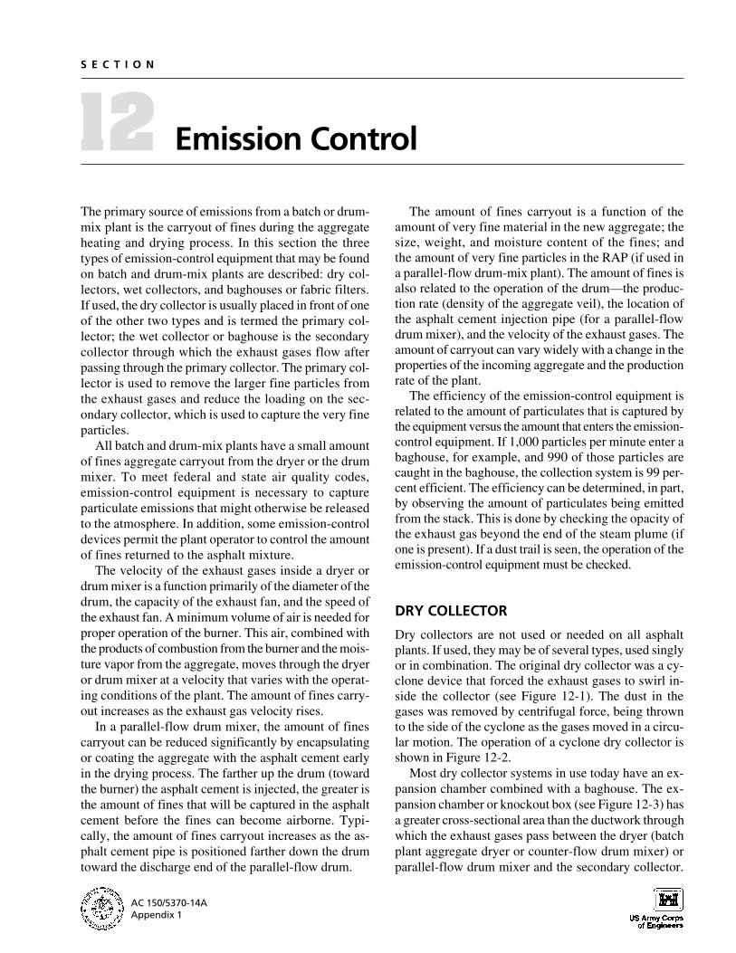
9727-12/Sec12 12/20/00 17:43 Page 105
S E C T I O N
12 Emission Control
The primary source of emissions from a batch or drum-mix plant is the carryout of fines during the aggregate heating and drying process. In this section the three types of emission-control equipment that may be found on batch and drum-mix plants are described: dry collectors, wet collectors, and baghouses or fabric filters. If used, the dry collector is usually placed in front of one of the other two types and is termed the primary collector; the wet collector or baghouse is the secondary collector through which the exhaust gases flow after passing through the primary collector. The primary collector is used to remove the larger fine particles from the exhaust gases and reduce the loading on the secondary collector, which is used to capture the very fine particles.
All batch and drum-mix plants have a small amount of fines aggregate carryout from the dryer or the drum mixer. To meet federal and state air quality codes, emission-control equipment is necessary to capture particulate emissions that might otherwise be released to the atmosphere. In addition, some emission-control devices permit the plant operator to control the amount of fines returned to the asphalt mixture.
The velocity of the exhaust gases inside a dryer or drum mixer is a function primarily of the diameter of the drum, the capacity of the exhaust fan, and the speed of the exhaust fan. A minimum volume of air is needed for proper operation of the burner. This air, combined with the products of combustion from the burner and the moisture vapor from the aggregate, moves through the dryer or drum mixer at a velocity that varies with the operating conditions of the plant. The amount of fines carry-out increases as the exhaust gas velocity rises.
In a parallel-flow drum mixer, the amount of fines carryout can be reduced significantly by encapsulating or coating the aggregate with the asphalt cement early in the drying process. The farther up the drum (toward the burner) the asphalt cement is injected, the greater is the amount of fines that will be captured in the asphalt cement before the fines can become airborne. Typically, the amount of fines carryout increases as the asphalt cement pipe is positioned farther down the drum toward the discharge end of the parallel-flow drum.
The amount of fines carryout is a function of the amount of very fine material in the new aggregate; the size, weight, and moisture content of the fines; and the amount of very fine particles in the RAP (if used in a parallel-flow drum-mix plant). The amount of fines is also related to the operation of the drum—the production rate (density of the aggregate veil), the location of the asphalt cement injection pipe (for a parallel-flow drum mixer), and the velocity of the exhaust gases. The amount of carryout can vary widely with a change in the properties of the incoming aggregate and the production rate of the plant.
The efficiency of the emission-control equipment is related to the amount of particulates that is captured by the equipment versus the amount that enters the emission-control equipment. If 1,000 particles per minute enter a baghouse, for example, and 990 of those particles are caught in the baghouse, the collection system is 99 percent efficient. The efficiency can be determined, in part, by observing the amount of particulates being emitted from the stack. This is done by checking the opacity of the exhaust gas beyond the end of the steam plume (if one is present). If a dust trail is seen, the operation of the emission-control equipment must be checked.
DRY COLLECTOR
Dry collectors are not used or needed on all asphalt plants. If used, they may be of several types, used singly or in combination. The original dry collector was a cyclone device that forced the exhaust gases to swirl inside the collector (see Figure 12-1). The dust in the gases was removed by centrifugal force, being thrown to the side of the cyclone as the gases moved in a circular motion. The operation of a cyclone dry collector is shown in Figure 12-2.
Most dry collector systems in use today have an expansion chamber combined with a baghouse. The expansion chamber or knockout box (see Figure 12-3) has a greater cross-sectional area than the ductwork through which the exhaust gases pass between the dryer (batch plant aggregate dryer or counter-flow drum mixer) or parallel-flow drum mixer and the secondary collector.
AC 150/5370-14A Appendix 1
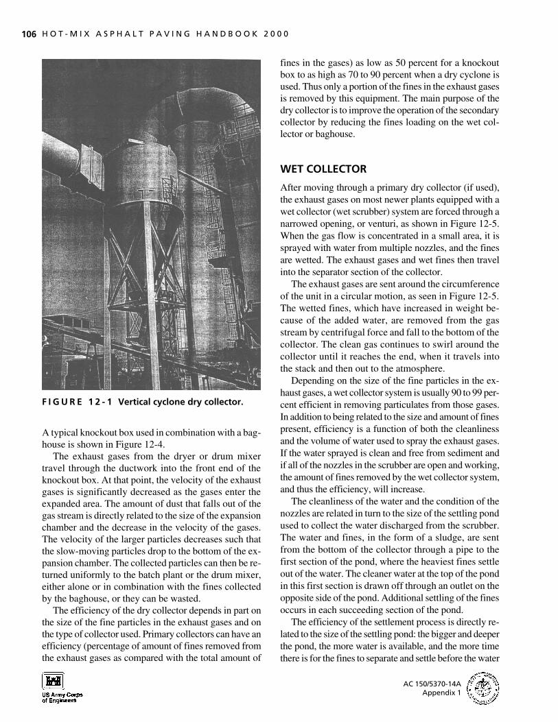
9727-12/Sec12 12/20/00 17:43 Page 106
106 H O T - M I X A S P H A L T P A V I N G H A N D B O O K 2 0 0 0
F I G U R E 1 2 - 1 Vertical cyclone dry collector.
A typical knockout box used in combination with a bag-house is shown in Figure 12-4.
The exhaust gases from the dryer or drum mixer travel through the ductwork into the front end of the knockout box. At that point, the velocity of the exhaust gases is significantly decreased as the gases enter the expanded area. The amount of dust that falls out of the gas stream is directly related to the size of the expansion chamber and the decrease in the velocity of the gases. The velocity of the larger particles decreases such that the slow-moving particles drop to the bottom of the expansion chamber. The collected particles can then be returned uniformly to the batch plant or the drum mixer, either alone or in combination with the fines collected by the baghouse, or they can be wasted.
The efficiency of the dry collector depends in part on the size of the fine particles in the exhaust gases and on the type of collector used. Primary collectors can have an efficiency (percentage of amount of fines removed from the exhaust gases as compared with the total amount of
fines in the gases) as low as 50 percent for a knockout box to as high as 70 to 90 percent when a dry cyclone is used. Thus only a portion of the fines in the exhaust gases is removed by this equipment. The main purpose of the dry collector is to improve the operation of the secondary collector by reducing the fines loading on the wet collector or baghouse.
WET COLLECTOR
After moving through a primary dry collector (if used), the exhaust gases on most newer plants equipped with a wet collector (wet scrubber) system are forced through a narrowed opening, or venturi, as shown in Figure 12-5. When the gas flow is concentrated in a small area, it is sprayed with water from multiple nozzles, and the fines are wetted. The exhaust gases and wet fines then travel into the separator section of the collector.
The exhaust gases are sent around the circumference of the unit in a circular motion, as seen in Figure 12-5. The wetted fines, which have increased in weight because of the added water, are removed from the gas stream by centrifugal force and fall to the bottom of the collector. The clean gas continues to swirl around the collector until it reaches the end, when it travels into the stack and then out to the atmosphere.
Depending on the size of the fine particles in the exhaust gases, a wet collector system is usually 90 to 99 percent efficient in removing particulates from those gases. In addition to being related to the size and amount of fines present, efficiency is a function of both the cleanliness and the volume of water used to spray the exhaust gases. If the water sprayed is clean and free from sediment and if all of the nozzles in the scrubber are open and working, the amount of fines removed by the wet collector system, and thus the efficiency, will increase.
The cleanliness of the water and the condition of the nozzles are related in turn to the size of the settling pond used to collect the water discharged from the scrubber. The water and fines, in the form of a sludge, are sent from the bottom of the collector through a pipe to the first section of the pond, where the heaviest fines settle out of the water. The cleaner water at the top of the pond in this first section is drawn off through an outlet on the opposite side of the pond. Additional settling of the fines occurs in each succeeding section of the pond.
The efficiency of the settlement process is directly related to the size of the settling pond: the bigger and deeper the pond, the more water is available, and the more time there is for the fines to separate and settle before the water
AC 150/5370-14A Appendix 1
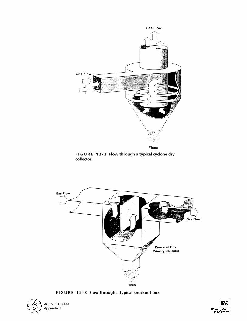
9727-12/Sec12 12/20/00 17:44 Page 107
F I G U R E 1 2 - 2 Flow through a typical cyclone dry collector.
F I G U R E 1 2 - 3 Flow through a typical knockout box.
AC 150/5370-14A Appendix 1
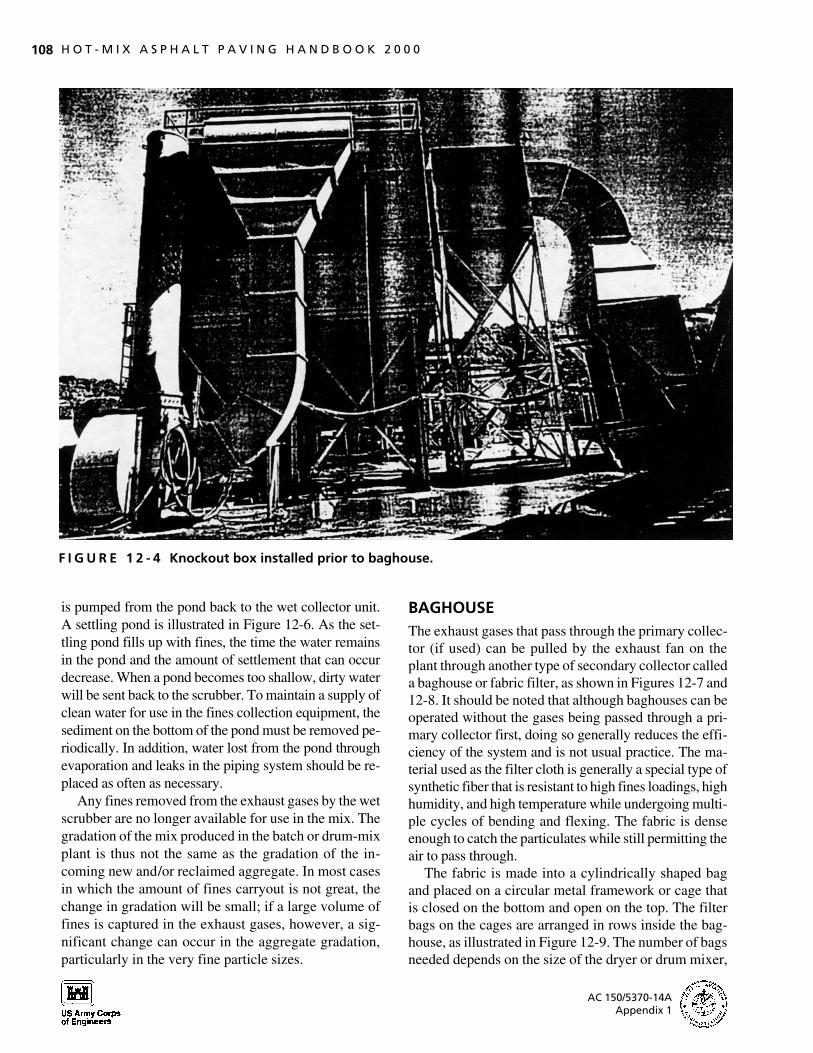
9727-12/Sec12 12/20/00 17:44 Page 108
108 H O T - M I X A S P H A L T P A V I N G H A N D B O O K 2 0 0 0
F I G U R E 1 2 - 4 Knockout box installed prior to baghouse.
is pumped from the pond back to the wet collector unit. A settling pond is illustrated in Figure 12-6. As the settling pond fills up with fines, the time the water remains in the pond and the amount of settlement that can occur decrease. When a pond becomes too shallow, dirty water will be sent back to the scrubber. To maintain a supply of clean water for use in the fines collection equipment, the sediment on the bottom of the pond must be removed periodically. In addition, water lost from the pond through evaporation and leaks in the piping system should be replaced as often as necessary.
Any fines removed from the exhaust gases by the wet scrubber are no longer available for use in the mix. The gradation of the mix produced in the batch or drum-mix plant is thus not the same as the gradation of the incoming new and/or reclaimed aggregate. In most cases in which the amount of fines carryout is not great, the change in gradation will be small; if a large volume of fines is captured in the exhaust gases, however, a significant change can occur in the aggregate gradation, particularly in the very fine particle sizes.
BAGHOUSE The exhaust gases that pass through the primary collector (if used) can be pulled by the exhaust fan on the plant through another type of secondary collector called a baghouse or fabric filter, as shown in Figures 12-7 and 12-8. It should be noted that although baghouses can be operated without the gases being passed through a primary collector first, doing so generally reduces the efficiency of the system and is not usual practice. The material used as the filter cloth is generally a special type of synthetic fiber that is resistant to high fines loadings, high humidity, and high temperature while undergoing multiple cycles of bending and flexing. The fabric is dense enough to catch the particulates while still permitting the air to pass through.
The fabric is made into a cylindrically shaped bag and placed on a circular metal framework or cage that is closed on the bottom and open on the top. The filter bags on the cages are arranged in rows inside the bag-house, as illustrated in Figure 12-9. The number of bags needed depends on the size of the dryer or drum mixer,
AC 150/5370-14A Appendix 1
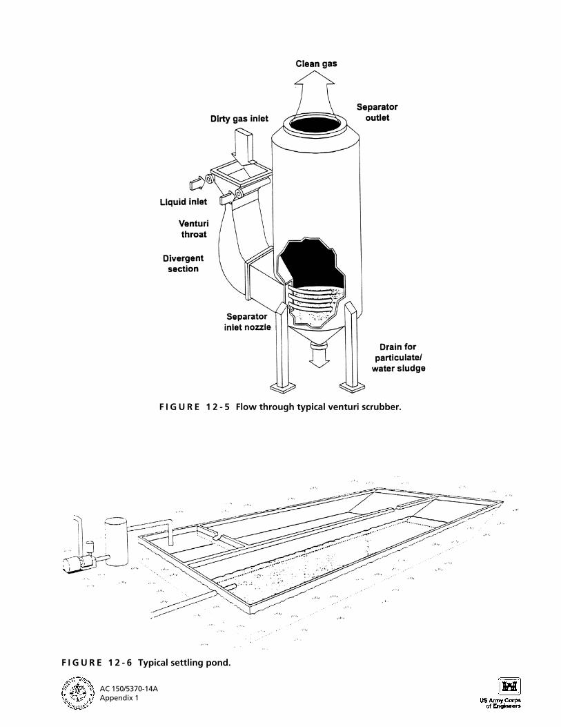
9727-12/Sec12 12/20/00 17:44 Page 109
F I G U R E 1 2 - 5 Flow through typical venturi scrubber.
F I G U R E 1 2 - 6 Typical settling pond.
AC 150/5370-14A Appendix 1
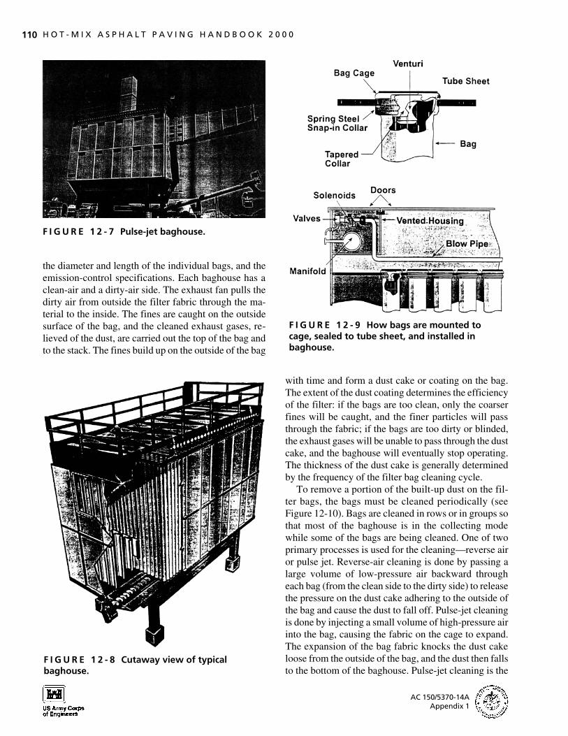
9727-12/Sec12 12/20/00 17:44 Page 110
110 H O T - M I X A S P H A L T P A V I N G H A N D B O O K 2 0 0 0
F I G U R E 1 2 - 7 Pulse-jet baghouse.
the diameter and length of the individual bags, and the emission-control specifications. Each baghouse has a clean-air and a dirty-air side. The exhaust fan pulls the dirty air from outside the filter fabric through the material to the inside. The fines are caught on the outside surface of the bag, and the cleaned exhaust gases, relieved of the dust, are carried out the top of the bag and to the stack. The fines build up on the outside of the bag
F I G U R E 1 2 - 8 Cutaway view of typical baghouse.
F I G U R E 1 2 - 9 How bags are mounted to cage, sealed to tube sheet, and installed in baghouse.
with time and form a dust cake or coating on the bag. The extent of the dust coating determines the efficiency of the filter: if the bags are too clean, only the coarser fines will be caught, and the finer particles will pass through the fabric; if the bags are too dirty or blinded, the exhaust gases will be unable to pass through the dust cake, and the baghouse will eventually stop operating. The thickness of the dust cake is generally determined by the frequency of the filter bag cleaning cycle.
To remove a portion of the built-up dust on the filter bags, the bags must be cleaned periodically (see Figure 12-10). Bags are cleaned in rows or in groups so that most of the baghouse is in the collecting mode while some of the bags are being cleaned. One of two primary processes is used for the cleaning—reverse air or pulse jet. Reverse-air cleaning is done by passing a large volume of low-pressure air backward through each bag (from the clean side to the dirty side) to release the pressure on the dust cake adhering to the outside of the bag and cause the dust to fall off. Pulse-jet cleaning is done by injecting a small volume of high-pressure air into the bag, causing the fabric on the cage to expand. The expansion of the bag fabric knocks the dust cake loose from the outside of the bag, and the dust then falls to the bottom of the baghouse. Pulse-jet cleaning is the
AC 150/5370-14A Appendix 1

9727-12/Sec12 12/20/00 17:44 Page 111
S E C T I O N 1 2 Emission Control 111
F I G U R E 1 2 - 1 0 Bags filtering air and being cleaned.
method used most commonly on most of the newer fabric filters. The particulates removed from the bags are collected for return to the plant or are wasted.
A baghouse can remove up to 99.9 percent of the fines in the exhaust gas stream. This efficiency is measured in part by the amount of pressure drop—generally in the range of 50 to 150 mm (2 to 6 in.) of water column— between the dirty and clean sides of the bags. If the pressure drop is too low [25 to 50 mm (1 to 2 in.)], the bags are too clean, so that some of the very fine dust particles will pass through the filter and travel up the stack and out to the atmosphere. If the pressure drop is too high [greater than 150 mm (6 in.)], the fines buildup on the bags is excessive, the exhaust gases will be restricted from passing through the fabric, and the capacity of the dryer or drum mixer will be reduced.
The efficiency of the baghouse will be affected if the temperature of the exhaust gases entering the baghouse is below the dew point—the temperature of the exhaust gas at which moisture begins to condense. The moisture, combined with the fines in the exhaust gases, forms a mudlike coating on the outside of the bags that cannot easily be removed during the bag-cleaning cycle. Should this happen, the pressure drop across the bags will increase significantly, reducing the efficiency of the bag-house and even choking off the burner flame in extreme cases. To prevent this from occurring, the baghouse
must be preheated by running the burner on “low fire” without aggregate in the drum before mix production begins each day.
If subjected to temperatures above 225°C (440°F) for extended periods of time, the synthetic fiber bags can char, disintegrate, and then burn. To prevent this, a temperature sensor and automatic shutdown devices are installed in the ductwork upstream of the baghouse. The sensor is typically set at a temperature of 205°C (400°F). If the temperature of the exhaust gases exceeds this value, the sensor sends a visual and/or audible signal to the plant operator or may automatically shut off the fuel flow to the burner. Some baghouses are fitted with automatic fire extinguisher devices to control a fire should one occur in the emission-control equipment.
The gradation of the asphalt mix produced in a batch or drum-mix plant may change depending on whether any or all of the baghouse fines are returned to the plant. If the collected dust is returned, the mix gradation will be approximately the same as the gradation of the incoming new and reclaimed aggregate (assuming minimal degradation of the aggregate during processing through the dryer or drum mixer). If the baghouse fines are wasted, there may be a considerable change in the mix gradation. Note that if the fines are returned, it is important that they be introduced into the batch or drum-mix plant continuously and uniformly.
AC 150/5370-14A Appendix 1

9727-12/Sec12 12/20/00 17:45 Page 112
112 H O T - M I X A S P H A L T P A V I N G H A N D B O O K 2 0 0 0
FUGITIVE DUST
Although the primary source of emissions from a batch or drum-mix plant is fines carryout, additional emissions are possible in the form of fugitive dust. This dust consists of material that leaks from the plant through holes in the equipment or ductwork while the plant is operating.
For a batch plant, the three most likely sources of fugitive dust are the hot elevator, the plant screens, and the pugmill. As the aggregate is delivered from the hot elevator to the screen deck, it passes over the vibrating screens. This movement creates dust, as does the mixing of aggregate in the plant pugmill during the dry-mix cycle. Fugitive dust can be eliminated by enclosing the screen deck area completely and tightly and by keeping the dry-mix time in the pugmill to a minimum. In addition, a scavenger air system (fugitive dust evacuation system) creates a negative air pressure inside the plant housing and greatly reduces the amount of dust carryout during plant operations. This system usually consists of ductwork with adjustable dampers extending from the screen deck, hot bins, weigh hopper, and pugmill to the inlet of a fugitive dust fan, which then blows the dust to the dust collection system. On some plants, a fugitive dust fan is not used; in this instance, the ductwork extends directly to the inlet of the secondary collector.
For both batch and drum-mix plants, holes in the emission-control equipment, primarily in the ductwork between the end of the dryer or drum mixer and the dry or wet collector, may allow the escape of fine aggregate particles or dust. These holes should be patched so that all of the dust in the exhaust gases will be drawn into the emission-control collectors. Further, the holes should be eliminated in order to prevent the exhaust fan from drawing in excess (leakage) air and reducing the
amount of air available for proper combustion of the fuel at the burner.
SUMMARY
The following key factors should be considered when monitoring the operation of the emission-control equipment:
The discharge of the exhaust gases from the stack should be observed for a dust trail at the end of the steam plume. If one exists, the operation of the emission-control equipment should be checked.
If a wet scrubber is used, the spray nozzles in the venturi should be checked to ensure that all are open and spraying water properly.
The cleanliness of the water being returned to the spray nozzles from the pond should be checked at the point at which the water is drawn from the pond to be returned to the plant by the water pump.
If a baghouse is used, the pressure drop across the bags should be in the range of 50 to 150 mm (2 to 6 in.) of water column.
The temperature of the exhaust gases entering the baghouse should be less than 205°C (400°F). An automatic shutoff device should be used to stop the operation of the plant if the exhaust gas temperature exceeds this value. The temperature of the gases entering the bag-house should be considerably less than this if the veil of aggregate inside the dryer or drum mixer is correct.
The gradation of the mix produced in the batch or drum-mix plant should be compared with the gradation used in the mix design process. The amount of change in gradation will depend on whether a wet scrubber system is used and whether the baghouse fines are returned to the plant or wasted.
AC 150/5370-14A Appendix 1