paper | lab on a chipmmb.bme.wisc.edu/research/beebepubs/beebe pubs/2367745537kim… · pumps.1–4...
TRANSCRIPT

Hydrogel-based reconfigurable components for microfluidic devices{
Dongshin Kimab and David J. Beebe*ab
Received 11th September 2006, Accepted 20th November 2006
First published as an Advance Article on the web 7th December 2006
DOI: 10.1039/b612995a
In situ liquid-phase photopolymerization (LP3) has been applied to the field of microfluidics to
create components within integrated systems. As an extension of LP3 technology, we present
reconfigurable components that utilize the swelling of hydrogels. These components can be
conveniently used to enhance microfluidic functions and applications. In order to utilize the
swelling characteristic of hydrogels to the fullest, we demonstrate strategies to increase the
swelling performance temporally and spatially. To this end, two successful applications using the
reconfigurable components were tested: (1) active walls to block or divert flow at different steps in
the fabrication or assay process, and (2) delivery pistons to move objects to specific locations
within the microchannels after device fabrication.
Introduction
Hydrogels belong to a class of polymeric materials that swell
upon hydration. Recently, hydrogels have been used in
microfluidic systems to provide actuation for valves and
pumps.1–4 Also, hydrogels possess many characteristics that
resemble or mimic biological systems and microenvironments,
such as the cross-linked nature of the extracelluar matrix, the
swelling behavior of biological tissues, and tension or spring
forces generated by muscles.5–7 Specifically, the swelling
phenomenon of stimuli-responsive hydrogels may aid in
understanding biological functions like muscle movement8–10
or plant motion.11,12
Fabrication of reconfigurable components is another area
where hydrogels can prove useful. The volumetric swelling
behavior inherent to stimuli-responsive hydrogels can be
utilized as functional components to reconfigure elements in
a system. In general, once a microdevice is completed via
traditional microfabrication methods, it is difficult to reconfi-
gure the device by, for example, changing the microchannel
path, relocating certain components, or sealing off areas.
Using active components as part of the system assembly
process provides new options typically not available via
traditional passive assembly.
In this paper, several basic characteristics of hydrogel
swelling will be discussed along with corresponding applica-
tions that employ hydrogel-based reconfigurable components.
Theory
To realize the utility of hydrogels, it is necessary to understand
their swelling behavior. Thus, swelling characteristics of
hydrogels are discussed and two reconfigurable components–
active walls and a delivery piston–are subsequently proposed.
Radial swelling vs. longitudinal swelling
While the basic swelling kinetics of hydrogels have been well
studied,13–20 the swelling behavior of hydrogels in different
shapes has barely been examined.2 To date, most hydrogel
kinetics data are based on circular hydrogel disks or on a
macro scale. To realize diverse microfluidic functions that
utilize the swelling of various shapes of hydrogels, additional
information regarding the relationship between geometry and
swelling is important. The swelling behavior of the hydrogel is
expected to vary significantly from a circular hydrogel disk to
a long, rectangular hydrogel bar when both components are
constricted by the top and bottom of the channel. Fig. 1 shows
the radial and longitudinal swelling for the hydrogel disk and
bar, respectively, when the diameter of the hydrogel disk and
the length of the hydrogel bar are identical. Both structures are
constricted between a channel top and bottom, thus preventing
swelling towards the top or bottom. The rate of the ionic shell
formation indicating the diffusion of the stimuli is the same
with both the hydrogel disk and hydrogel bar. However, the
smallest dimension of the hydrogel bar (i.e., width) is much
smaller than that of the hydrogel disk (i.e., diameter), and
therefore the swelling time of the hydrogel bar, is expected to
be considerably faster than that of the hydrogel disk.21,22
Channel height can also affect the swelling behavior, as
shown in Fig. S1 (ESI).{ According to Hooke’s law, the
magnitude of the normal reacting force (Fn) onto the hydrogel
bar is proportional to the amount of constricted perpendicular
swelling (dy) if it is assumed that the swollen hydrogel behaves
like a Hookean material and has negligible weight.13
Additionally, the frictional force (Ff) on the top and bottom
is proportional to Fn (i.e. Ff = mFn, where m is the frictional
coefficient). If there is no friction present on the top and
bottom, the volume of swollen hydrogel bar (V) can be
represented as:
V = wlh = nV0 = nw0l0h0 (1)
aDepartment of Mechanical Engineering, University of Wisconsin,Madison, WI 53706, USAbDepartment of Biomedical Engineering, University of Wisconsin, 2142Engineering Centers Building, 1550 Engineering Drive, Madison,WI 53706, USA. E-mail: [email protected]; Tel: (608) 262-2260{ Electronic supplementary information (ESI) available:Supplementary figures. See DOI: 10.1039/b612995a
PAPER www.rsc.org/loc | Lab on a Chip
This journal is � The Royal Society of Chemistry 2007 Lab Chip, 2007, 7, 193–198 | 193

where w, l, h, and n are width, length, thickness, and the extent
of volume change, respectively. Variables with naught sub-
scripts represent the initial values. If we use a for aspect ratio
of width over length of the hydrogel bar, which is assumed to
be same for both the initial and swollen states, eqn (1) becomes
eqn (2):
V = al2h = nal20h0 (2)
Since h equals h0 when the hydrogel bar is constricted by the
channel top and bottom, the longitudinal swelling distance
(dx) is:
dx~l{l0~ffiffiffi
np
{1� �
l0 (3)
proving that dx is independent of h. Thus, dx will theoretically
be the same for both thick and thin hydrogel bars with the
same initial length when they reach equilibrium. In reality,
however, Ff exists on both the channel top and bottom. Ff for
the thick bar is larger because of a greater dy; as such, dx of the
thick hydrogel bar is expected to be smaller than that of the
thin hydrogel bar.
Buckling and active wall
Hydrophilicity of the channel surfaces increases the frictional
stress on a contacting material in the presence of water at the
interface due to the capillary force, which ultimately affects the
hydrogel swelling.23,24 If Ff is larger than the longitudinal
swelling force or if the concentration of the stimulus is not
uniform throughout the whole perimeter, the hydrogel bar
swells irregularly and therefore buckles as shown in Fig. 2. To
avoid buckling, the hydrogel bar and microfluidic chamber
need to be optimized for linear swelling so that swelling starts
and proceeds evenly throughout the whole perimeter of the
hydrogel bar. If one end of the hydrogel bar is constricted, the
hydrogel bar swells toward the free end. This unbuckled
hydrogel bar has been used as a micro-valve.24
Intentional buckling of hydrogel bars can be used for certain
microfluidic functions. If both sides of the hydrogel bar are
constricted, the reacting force (F) at the end of hydrogel bar,
generated by longitudinal swelling, induces buckling since the
bar acts like an elastic beam under axial compression (Fig. S2{).
The buckled hydrogel bar seals the channel and can therefore be
used as a blocking component within microfluidic systems.
The critical buckling load, Pcr, (i.e., any load increase
beyond this critical value will lead to buckling) of a hydrogel
bar which has both ends constricted, is given by Euler’s
formula:
Pcr~EIp2
l2(4)
where E, I, and l are Young’s modulus of the hydrogel bar,
area moment of inertia of the cross-section, and length of the
hydrogel bar, respectively.25 According to eqn (4), the critical
buckling load of longer hydrogels is smaller than that of the
shorter hydrogels when they are made of same material and
have same cross-sectional area. As a result, the longer
Fig. 1 Comparison between radial and longitudinal swelling for the hydrogel disk and bar when the diameter of the hydrogel disk and the length
of the hydrogel bar are identical. Both structures are constricted between a channel top and bottom, thus preventing swelling towards the top or
bottom. The rate of the ionic shell formation indicating the diffusion of the stimuli is the same with both the hydrogel disk and hydrogel bar.
However, the smallest dimension of the hydrogel bar (i.e., width) is much smaller than that of the hydrogel disk (i.e., diameter), and therefore the
swelling time of the hydrogel bar, is expected to be considerably faster than that of the hydrogel disk.
Fig. 2 Buckled hydrogel bar. The hydrogel bar is constricted by the
rigid post on left. Due to uneven swelling, part of the bar buckles.
194 | Lab Chip, 2007, 7, 193–198 This journal is � The Royal Society of Chemistry 2007

hydrogels will buckle faster than the shorter hydrogels under
the same swelling condition. Thus, it is possible to program a
buckling time by geometrically adjusting the length of
hydrogels.
An active wall is an example of a microfluidic component
using the buckling phenomenon of a hydrogel bar. An active
wall can function as a blocking component that prevents or
reconfigures flow in certain channels or parts of a microfluidic
device. The active wall is comprised of two rigid posts, a
responsive hydrogel bar, and straight channel walls as shown
in Fig. S2.{ The channel is open during normal operation
(Fig. S2a) and is closed by a buckled hydrogel (Fig. S2b) upon
introduction of a swelling stimulus such as pH or temperature.
The active wall can be used to enhance fabrication quality or
improve device performance in microfluidic systems. One
example is a detour channel—created by the active wall—for
protecting certain sensitive components (e.g. filter or readout
disk) from chemicals (used during other fabrication steps) that
could degrade the component and, in turn, adversely affect
component performance.
Flipping and delivery piston
As discussed previously, the hydrogel bar can be designed to
swell longer distances as compared to the hydrogel disk.
However, the longer the bar, the easier it can buckle or flip
over, resulting in improper function. To make the hydrogel bar
swell longer distances without any buckling or flipping over in
irregular, non-repeatable directions, the hydrogel bar can be
formed to have a slanted cross-section, as depicted in Fig. S3.{As the hydrogel bar swells, the off-center reacting forces (Fn)
act on the top and bottom of the hydrogel bar; once the
moment (M) of the hydrogel bar becomes large enough to
overcome the negative moment (Mf) caused by Ff, the hydrogel
bar flips over. By exploiting this phenomenon, it is possible to
control the direction of flipping. Once the hydrogel bar has
flipped over, it does not touch the top or bottom channel
surface; the hydrogel bar can therefore fully swell and contract
with minimal hindrance (i.e., friction).
Long distance swelling can function similar to a micro-
actuator and be used as a delivery tool in microfluidic systems.
Current technologies, such as optical tweezers and dielectro-
phoretic traps which facilitate entrapment or movement of
particles, are not suitable for particles ranging beyond 10 mm
in diameter.26–29 A delivery piston that capitalizes on the
physical reorientation (90u rotation about the x-axis) of a
rectangular hydrogel bar can be employed to physically move
or reposition relatively large objects inside a microchannel
(Fig. S4{). When triggered, the hydrogel piston can push a disk
to a designated location for subsequent analysis or treatment.
The ability to relocate particles, similar to the function of a
conveyor belt in a macro-system, grants a certain amount of
autonomy to microdevices.
Results and discussion
Radial swelling vs. longitudinal swelling
Theoretically, longitudinal swelling distance of the hydrogel
bar should be equal to the radial swelling distance of the
hydrogel disk due to the same ratio of volumetric change.
Thus, the maximum swelling distance would be same for the
disk and bar if enough swelling time (i.e., hours) was allowed.
The swelling rate and swelling distance of the hydrogel bar was
faster and longer, respectively, than that of the hydrogel disk
during the 50 min swelling experiment, as anticipated (Fig. 3
and Table 1), for both 125 mm and 250 mm thick devices. As a
result, the hydrogel bar is a superior design when compared to
the circular hydrogel disk because of its smaller volume and
faster swelling. The thickness of the hydrogel also affected
swelling behavior. The swelling of the thin hydrogels (125 mm)
was greater in magnitude than that of the thick hydrogels
(250 mm), presumably due to the lower frictional force of the
thin bar owing to the smaller perpendicular swelling (dy)
(Fig. S1{). Thus, thinner hydrogels are better to achieve longer
swelling.
Buckling and active wall
Fig. S5{ shows the result of preliminary tests to investigate the
buckling time and mode of the active walls in different length.
The time before the buckling started to close the active walls
took 4 min, 10 min, and 20 min for 4.8, 3.8, and 2.8 mm
hydrogels, respectively. The length of time to seal the channel
was greater for the shorter bars, as predicted by eqn (4).
Fig. 4 shows the result of the active wall using 2.8 mm long
hydrogel bars to protect a filter during other manufacturing
Fig. 3 Comparison of radial (disk) and longitudinal (bar) swelling.
The swelling speeds of the hydrogel bars are significantly faster than
those of the hydrogel disks.
Table 1 Comparison of measured swelling distance and time betweenhydrogel bar and disk.
Thickness/mm
Swollen distance/mm aSwelling time/min
Bar Disk Bar Disk
125 205 133 10.4 38.5250 159 107 10.3 40.8a Time taken to reach 95% of the maximum swelling distance.
This journal is � The Royal Society of Chemistry 2007 Lab Chip, 2007, 7, 193–198 | 195

steps. The dark area between the top and bottom channels is
an in situ fabricated filter. The active walls blocked auxiliary
channels used during preliminary steps of the filter fabrication
process, successfully diverting flow through the filter. The
buckling of the hydrogel bars closed the auxiliary channel and
remained closed under pressures up to 207 kPa, which was the
maximum measurable pressure of the current measurement
system.
The active wall made of the temperature-sensitive hydrogel
tended to swell without buckling (Fig. S6{). The swelling and
shrinking of the temperature-sensitive hydrogel was rapid and
was complete in less than two minutes. Although it requires
additional materials for operation, such as heating and/or
cooling devices, the temperature-sensitive gels can function as
active walls or active micro-valves that are chemically resistant
to swelling or shrinking upon interaction with sample fluid.
An active wall may also function to reconfigure channel
networks or isolate designated parts of a device. In addition, if
the swelling of the hydrogel bar is adjusted to have a certain
degree of allowable pressure, the active wall may serve as a
safety valve or regulator to prevent excessive pressure build-up
inside a microfluidic chamber.
Flipping and delivery piston
As a result of flipping, a delivery piston was able to move a
disk to a designated location (Fig. 5). The hydrogel piston was
photopolymerized inside the channel to have a slanted angle;
due to the unidirectional net moment developed during
swelling, this allowed the slanted piston to flip in one direction.
The flipping occurred at the tip (Fig. 5b) and propagated
toward the base of the hydrogel piston (Fig. 5c). After
10 minutes of swelling, the 500 mm disk was moved to its
designated location by the hydrogel piston. The resultant
swollen distance of the piston was 1.8 mm, which could be
adjusted by using buffer solutions of varying pH.2 Once the
hydrogel piston had flipped over, it would not flip back to its
initial orientation even in the contracted state because there
was no reaction force to realize the negative rotation moment.
This delivery piston provides new functionality for moving
big objects such as readout disks or possibly embryos30 inside
microfluidic devices. For example, the delivery piston could be
used to reposition a functionalized disk for enzyme-linked
Fig. 4 Active walls for filter fabrication. Once the filter was
fabricated and washed (a), buckled hydrogels, functioning as active
walls, diverted flow through the filter (b). The dyed color indicates the
rinsing and sample flow.
Fig. 5 Time-lapse images of the hydrogel delivery piston. The 500 mm diameter disk was moved into the designated location by flipping of the
hydrogel piston (200 mm wide; 3.3 mm long) after 10 min swelling. The resultant swollen distance of the piston was 1.8 mm. The white dotted circles
in (b) and (c) represent the point where the bar has flipped.
196 | Lab Chip, 2007, 7, 193–198 This journal is � The Royal Society of Chemistry 2007

immunosorbent assay (ELISA), a detection procedure used in
diagnostics that utilizes antibody specificity and enzymatic
reactions.31 One of the problems with ELISA within a
microfluidic device is nonspecific background signal from the
surface of the treatment channel, which lowers the signal to
noise ratio. One method used to address this problem has been
the use of blocking agents such as albumin. The delivery piston
could be an alternative way to enhance the signal by
repositioning the readout disk to a clean channel that has
not been exposed to the fluorophore, ultimately avoiding the
use of albumin or other blocking agents typically employed for
ELISA.
Conclusions
Swelling characteristics of hydrogels were studied to better
understand their behavior and provide insight for exploring
new microfluidic functions and components. The results
suggest that the hydrogel bar is the preferred geometry for
actuator functions than the circular design of the hydrogel disk
due to the bar’s faster swelling time. Next, methods utilizing
the elastic energy of swelling hydrogels were proposed and
demonstrated with novel reconfigurable microfluidic compo-
nents, such as active walls and delivery pistons: active walls
either reconfigured the channel network for protection of
system components (e.g. the in situ fabricated filter) or simply
redirected flow; additionally, a delivery piston repositioned a
relatively large object (500 mm disk). The reconfigurable
components demonstrated in this paper were accomplished
by combining a passive element (channels formed during LP3)
and an active element (stimuli-responsive hydrogel). These
components may be expanded upon to create other compo-
nents, such as safety or release valves, degradable blocking
components, and microfluidic actuators. The use of stimuli-
responsive materials to reconfigure existing components
further increases the options available to microfluidic
designers.
Methods
Ethylene glycol dimethacrylate (EGDMA) was purchased
from Polysciences Inc. (Warrington, PA). Isobornyl acrylate
(IBA) was obtained from Surface Specialties, (Smyma, GA).
N-isopropylacrylamide (NIPAAm), N,N9-methylenebisacryl-
amide (NMBA), and dimethylsulfoxide (DMSO) were from
Acros Organics (Geel, Belgium). 2-hydroxyethyl methacrylate
(HEMA), 2,2-dimethoxy-2-phenylacetophenone (DMPA), tet-
raethyleneglycol dimethacrylate (TEGDMA), and acrylic acid
(AA) were purchased from Sigma-Aldrich Corp. (St. Louis,
MO). IBA and HEMA were vacuum distilled before use, while
all the other materials were used as obtained.
Hydrogel bar and disk for swelling comparison
Hydrogel bars (180 mm wide, 1 mm long; 125 mm and 250 mm
thick) and disks (1 mm od; 125 mm and 250 mm thick) were
fabricated from a HEMA-based hydrogel prepolymer contain-
ing HEMA, DMPA, and EGDMA (1 : 0.03 : 0.03 weight
ratio). Channel networks and chambers to enclose the
hydrogels were fabricated from an IBA-based prepolymer
mixture consisting of IBA, TEGDMA, and DMPA (1.9 : 0.1 :
0.06 weight ratio) using the tectonics platform.32
A polycarbonate cartridge with an adhesive gasket at the
edges (125 mm or 250 mm thick for corresponding hydrogel
thickness; Grace Bio-Labs, Bend, OR) was attached to a
polycarbonate sheet fixed on a microscope glass slide and filled
with the IBA-based prepolymer. A film photomask detailing
the channels and chambers was placed on top of the cartridge
and exposed to UV light (365 nm, 12 mW cm22, 12 s) (EXFO
Acticure 4000, Mississauga, Ontario, Canada). After removing
the unpolymerized monomer material with a vacuum pump,
the channel was flushed deionized (DI) water. The channel was
then filled with DI water and exposed again to UV light
(12 mW cm22, 12 s) to obtain well-defined channel walls and
chambers. Next, the chamber was filled with the HEMA-based
hydrogel prepolymer. The photomask representing the shape
of a hydrogel bar or disk was placed on top of the device and
exposed to UV light (24 mW cm22, 60 s) with similar post-
polymerization treatment.
Radial and longitudinal swelling were compared using
hydrogel bars and disks. The prepared device was placed on
a stereoscope and swelling was initiated by introducing DI
water in the chamber. Time-lapse images were taken by a
digital camera (DFC300FX, Leica, Cambridge, UK) attached
to the stereoscope. The images were calibrated and analyzed to
quantify swelling of the hydrogel bars and disks using an
imaging software (IM50, Leica, Cambridge, UK).
Filter device employing active wall
Fig. 4 shows the design of a microfluidic filter that is protected
by active walls during other manufacturing steps. Channel
networks, chambers, and hydrogel bars were fabricated using
the technique outlined in the previous section. Polycarbonate
cartridges of 250 mm thick were used for the filter devices.
Three different lengths of hydrogel bars (2.8, 3.8 and 4.8 mm
with 200 mm width) were tested to investigate the time range of
buckling by DI water. 2.8 mm long hydrogel bars were chosen
for the filter device to have 20 minutes before the active wall
closed so that there was enough time for the porous filter
photopolymerization and 5–10 minutes of rinsing. Next, the
chamber was filled with a filter mixture containing HEMA,
DMPA, EGDMA, and water (0.22 : 0.002 : 0.008 : 0.78 weight
ratio). A porous filter was photopolymerized in situ33 by
placing a photomask on top of the device and exposing to UV
light (25 mW cm22, 4 min). DI water was introduced to rinse
unpolymerized filter material from the area. The rinsing fluid
passed alongside (not through) the fabricated filter during the
cleaning process (Fig. 4a). Twenty minutes after polymeriza-
tion, the active walls buckled and closed the auxiliary channels
(Fig. 4b). Closed active walls were investigated separately to
characterize the blocking function with a flow rate measure-
ment method developed previously.34 As an alternate
approach, a temperature-sensitive hydrogel prepolymer con-
sisting of NIPAAm, NMBA, DMPA, DMSO, and water
(0.545 : 0.015 : 0.0385 : 0.75 : 0.25 weight ratio)35,36 was used to
make active walls that were not stimulated by sample fluid.
The temperature-responsive active walls were closed by cool-
ing to less than 20 uC.
This journal is � The Royal Society of Chemistry 2007 Lab Chip, 2007, 7, 193–198 | 197

Delivery piston
Channel networks and chambers (250 mm thick) were
fabricated according to the above protocols. A base-responsive
hydrogel prepolymer consisting of AA, HEMA, EGDMA,
and DMPA (4.05 : 29.3 : 0.334 : 1 weight ratio) filled the
channel network and the hydrogel piston (200 mm wide, 3.3 mm
long) was polymerized. The piston was exposed to UV light
that was slanted at approximately 10 degrees in order to
produce a slanted shape; such a slant allowed for controlled
flipping in one direction (Fig. S6{). A flat disk (500 mm
diameter, 125 mm thick) was inserted into its initial location by
blowing with nitrogen gas. The hydrogel piston was swelled
using a 10 mM buffer, pH 10.
Acknowledgements
This research was partly supported by the US Department of
Homeland Security (DHS) (grant number N-00014-04-1-
0659), through a grant awarded to the National Center for
Food Protection and Defense (NCFPD) at the University of
Minnesota and by a grant from DARPA-MTO (F30602-00-1-
0570).
References
1 A. K. Agarwal, S. S. Sridharamurthy, D. J. Beebe and H. Jiang,Programmable Autonomous Micromixers and Micropumps,J. Microelectromech. Syst., 2005, 14(6), 1409–1421.
2 D. J. Beebe, J. S. Moore, J. M. Bauer, Q. Yu, R. H. Liu,C. Devadoss and B. H. Jo, Functional hydrogel structures forautonomous flow control inside microfluidic channels, Nature,2000, 404(6778), 588–590.
3 R. H. Liu, Q. Yu and D. J. Beebe, Fabrication and characteriza-tion of hydrogel-based microvalves, J. Microelectromech. Syst.,2002, 11(1), 45–53.
4 A. Richter, D. Kuckling, S. Howitz, T. Gehring and K. F. Arndt,Electronically controllable microvalves based on smart hydrogels:Magnitudes and potential applications, J. Microelectromech. Syst.,2003, 12(5), 748–753.
5 A. Batorsky, J. H. Liao, A. W. Lund, G. E. Plopper andJ. P. Stegemann, Encapsulation of adult human mesenchymalstem cells within collagen-agarose microenvironments, Biotechnol.Bioengin., 2005, 92(4), 492–500.
6 H. Kurihara and T. Nagamune, Cell adhesion ability of artificialextracellular matrix proteins containing a long repetitive Arg-Gly-Asp sequence, J. Biosci. Bioeng., 2005, 100(1), 82–87.
7 Y. N. Yan, X. H. Wang, Z. Xiong, H. X. Liu, F. Liu, F. Lin,R. D. Wu, R. J. Zhang and Q. P. Lu, Direct construction of athree-dimensional structure with cells and hydrogel, J. Bioact.Compat. Polym., 2005, 20(3), 259–269.
8 T. Kaneko, Development of liquid crystalline hydrogel soft-actuator working under body temperature range, KobunshiRonbunshu, 2005, 62(8), 373–379.
9 R. Yoshida, Design of functional polymer gels and theirapplication to biomimetic materials, Curr. Org. Chem., 2005,9(16), 1617–1641.
10 E. A. Moschou, S. F. Peteu, L. G. Bachas, M. J. Madou andS. Daunert, Artificial muscle material with fast electroactuationunder neutral pH conditions, Chem. Mater., 2004, 16(12),2499–2502.
11 Y. Forterre, J. M. Skotheim, J. Dumais and L. Mahadevan, Howthe Venus flytrap snaps, Nature, 2005, 433(7024), 421–425.
12 J. M. Skotheim and L. Mahadevan, Physical limits and designprinciples for plant and fungal movements, Science, 2005,308(5726), 1308–1310.
13 S. K. De, N. R. Aluru, B. Johnson, W. C. Crone, D. J. Beebe andJ. Moore, Equilibrium swelling and kinetics of pH-responsive
hydro g e l s : mod e l s , expe r im ent s , a nd s imula t i ons ,J. Microelectromech. Syst., 2002, 11(5), 544–555.
14 Q. Yu, J. M. Bauer, J. S. Moore and D. J. Beebe, Responsivebiomimetic hydrogel valve for microfluidics, Appl. Phys. Lett.,2001, 78(17), 2589–2591.
15 M. G. Olsen, J. M. Bauer and D. J. Beebe, Particle imagingtechnique for measuring the deformation rate of hydrogelmicrostructures, Appl. Phys. Lett., 2000, 76(22), 3310–3312.
16 J. Valencia and I. F. Pierola, Swell ing kinetics ofpoly(N-vinylimidazole-co-sodium styrenesulfonate) hydrogels,J. Appl. Polym. Sci., 2002, 83(1), 191–200.
17 S. K. Bajpai, Swelling–deswelling behavior of poly(acrylamide-co-maleic acid) hydrogels, J. Appl. Polym. Sci., 2001, 80(14),2782–2789.
18 X. Qu, A. Wirsen and A. C. Albertsson, Structural change andswelling mechanism of pH-sensitive hydrogels based on chitosanand D,L-lactic acid, J. Appl. Polym. Sci., 1999, 74(13), 3186–3192.
19 S. J. Kim, H. I. I. Kim, S. J. Park and S. I. Kim, Shape changecharacteristics of polymer hydrogel based on polyacrylic acid/poly(vinyl sulfonic acid) in electric fields, Sens. Actuators, A, 2004,115(1), 146–150.
20 C. Khoury, T. Adalsteinsson, B. Johnson, W. C. Crone andD. J. Beebe, Tunable microfabricated hydrogels—A study inprotein interaction and diffusion, Biomed. Microdevices, 2003, 5(1),35–45.
21 T. Tanaka, E. Sato, Y. Hirokawa, S. Hirotsu and J. Peetermans,Critical kinetics of volume phase-transition of gels, Phys. Rev.Lett., 1985, 55(22), 2455–2458.
22 E. S. Matsuo and T. Tanaka, Kinetics of discontinuous volumephase-transition of gels, J. Chem. Phys., 1988, 89(3), 1695–1703.
23 D.-I. Kim, H.-S. Ahn and D.-H. Choi, Effect of surfacehydrophilicity and water vapor pressure on the interfacial shearstrength of adsorbed water layer, Appl. Phys. Lett., 2004, 84(11),1919–1921.
24 D. Kim and D. J. Beebe, A bi-polymer micro one-way valve, Sens.Actuators, A, 2006, DOI: 10.1016/j.sna.2006.11.004.
25 R. D. Cook and W. C. Young, Advanced Mechanics of Materials,2nd edn, 1999, Prentice-Hall, Inc., Upper Saddle River, NJ, p. 481.
26 D. G. Grier, A revolution in optical manipulation, Nature, 2003,424(6950), 810–816.
27 J. Voldman, R. A. Braff, M. Toner, M. L. Gray and M. A. Schmidt,Holding forces of single-particle dielectrophoretic traps, Biophys.J., 2001, 80(1), 531–541.
28 S. Rajaraman, H. Noh, P. J. Hesketh and D. S. Gottfried, Rapid,low cost microfabrication technologies toward realization ofdevices for dielectrophoretic manipulation of particles andnanowires, Sens. Actuators, B, 2006, 114(1), 392–401.
29 D. R. Albrecht, G. H. Underhill, T. B. Wassermann, R. L. Sah andS. N. Bhatia, Probing the role of multicellular organization inthree-dimensional microenvironments, Nat. Methods, 2006, 3(5),369–375.
30 I. K. Glasgow, H. C. Zeringue, D. J. Beebe, S. J. Choi, J. T. Lyman,N. G. Chan and M. B. Wheeler, Handling individual mammalianembryos using microfluidics, IEEE Trans. Biomed. Eng., 2001,48(5), 570–578.
31 J. Moorthy, G. A. Mensing, D. Kim, S. Mohanty, D. T. Eddington,W. H. Tepp, E. A. Johnson and D. J. Beebe, Microfluidic tectonicsplatform: A colorimetric, disposable botulinum toxin enzyme-linked immunosorbent assay system, Electrophoresis, 2004, 25,1705–1713.
32 D. J. Beebe, J. S. Moore, Q. Yu, R. H. Liu, M. L. Kraft, B.-H. Joand C. Devadoss, Microfluidic tectonics: A comprehensiveconstruction platform for microfluidic systems, Proc. Natl. Acad.Sci. U. S. A., 2000, 97(25), 13488–13493.
33 J. Moorthy and D. J. Beebe, In situ fabricated porous filters formicrosystems, Lab Chip, 2003, 3(2), 62–66.
34 D. Kim, N. C. Chesler and D. J. Beebe, A method for dynamicsystem characterization using hydraulic series resistance, Lab Chip,2006, 6(5), 639–644.
35 L. Dong, A. K. Agarwal, D. J. Beebe and H. R. Jiang, Adaptiveliquid microlenses activated by stimuli-responsive hydrogels,Nature, 2006, 442(7102), 551–554.
36 H. van der Linden, W. Olthuis and P. Bergveld, An efficientmethod for the fabrication of temperature-sensitive hydrogelmicroactuators, Lab Chip, 2004, 4(6), 619–624.
198 | Lab Chip, 2007, 7, 193–198 This journal is � The Royal Society of Chemistry 2007

Supplementary Material (ESI) for Lab on a Chip This journal is © The Royal Society of Chemistry 2006
<Supplemental figures>
Figure S1 Force diagram of a cross-sectioned hydrogel bar or disk. The normal reacting force (Fn) onto the hydrogel bar or disk induced by swelling is proportional to the amount of constricted perpendicular swelling (δy) according to Hooke’s law when the swollen hydrogel is assumed to be a Hookean material and to have negligible weight. F and Ff indicate the longitudinal swelling force and frictional force, respectively.
(a) Top view of a hydrogel bar before buckling
(b) Top view of a hydrogel bar after buckling
Figure S2 Schematic illustration of a hydrogel bar undergoing buckling. The reacting force (F) at the end of hydrogel bar - induced by swelling of the hydrogel - causes buckling since the hydrogel bar acts like an elastic beam under axial compression.
Fn
Fn F f Channel top
Hydrogel bar or disk
δy
δx
F
Channel bottom Center line
F f
Swollen size
Channel wall Hydrogel bar
Post
FF
Post
Supplementary Material (ESI) for Lab on a Chip This journal is © The Royal Society of Chemistry 2006
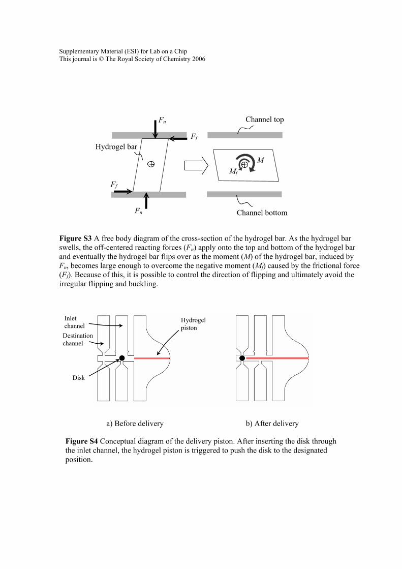
Figure S3 A free body diagram of the cross-section of the hydrogel bar. As the hydrogel bar swells, the off-centered reacting forces (Fn) apply onto the top and bottom of the hydrogel bar and eventually the hydrogel bar flips over as the moment (M) of the hydrogel bar, induced by Fn, becomes large enough to overcome the negative moment (Mf) caused by the frictional force (Ff). Because of this, it is possible to control the direction of flipping and ultimately avoid the irregular flipping and buckling.
a) Before delivery b) After delivery
Figure S4 Conceptual diagram of the delivery piston. After inserting the disk through the inlet channel, the hydrogel piston is triggered to push the disk to the designated position.
Fn
M
Fn
Ff
Channel top
Channel bottom
Ff Mf
Hydrogel bar
Hydrogel piston
Inlet channel
Destination channel
Disk

Supplementary Material (ESI) for Lab on a Chip This journal is © The Royal Society of Chemistry 2006
(a) Buckling of 4.8 mm long hydrogel bar
(b) Buckling of 3.8 mm long hydrogel bar
(c) Buckling of 2.8 mm long hydrogel bar
Figure S5 Buckling of hydrogel bars polymerized to have a different length. The time before the buckling started to close the active walls took 4 min, 10 min, and 20 min for 4.8, 3.8, and 2.8 mm hydrogel bars, respectively.

Supplementary Material (ESI) for Lab on a Chip This journal is © The Royal Society of Chemistry 2006
(a) Contracted state of temperature sensitive hydrogel at 50°C
(b) Swollen state of temperature sensitive hydrogel below 20°C
Figure S6 Image of an active wall using a temperature-sensitive hydrogel. The temperature-sensitive hydrogel tended to swell without buckling.

Supplementary Material (ESI) for Lab on a Chip This journal is © The Royal Society of Chemistry 2006
Figure S7 Cross-sectional view of flipping. Once the channel was fabricated, the hydrogel pre-polymer filled the channel and the hydrogel bar was polymerized in a slanted shape due to slanting of UV light with respect to position of the device.
Photo mask
Hydrogel prepolymer Polymerized Hydrogel bar
UV