page 21-1 unit 21 - secrets of engineering · at the instant shown it is in the horizontal xz plane...
TRANSCRIPT

Page 21-1
Unit 21Couples and Resultants with Couples
Couples
A couple is defined as ___________________________________________________________
__________________________________________________________________________ (21-5)
Moment of Couple
The coplanar forces F1 and F2 make up a couple and the coordinate axes are chosen so that the forces lie in the x-y plane.
The moments of F1 and F2 about the general point (x,y,z) are
(1.) M1 = ____________________________ M2 = ____________________________hence the total moment
MT = (r1 } F1) + (r2 } F2)Making use of the fact that F1 = -F2 and rearranging the equation we find
(2.) MT = _______________________Thus demonstrating that: "The moment of a couple is the moment of one of the forces about any point on the line of action of the other force, and it has the same moment about any other point in space."
$ Return to Frame 21-13

Page 21-2Characteristics of a Couple
The characteristics of a couple are magnitude and direction.
The magnitude of a couple is given by _____________________________________________
_________________________________________________________________________ (21-16)
The direction of a couple is given by _______________________________________________
__________________________________________________________ (21-16, 21-17, or 21-25)
Couples are equivalent if ________________________________________________________
_________________________________________________________________________ (21-21)
Represent a couple of 60k ft-lb as:
(1.) two 20 lb forces in the x-y plane (2.) a curved arrow
(3.) a vector
$ Return to Frame 21-30

Page 21-3Problem 21-1
Resolve the force at A into an equivalent force system consisting of a force through B and a couple.
Problem 21-2
Replace the 20 kip eccentric load on the column with an equivalent force system consisting of a force acting through G, the centroid of the cross-section and a couple.
$ Return to Frame 21-38
Page 22-1
Unit 22Equivalent Force Systems
Resultants
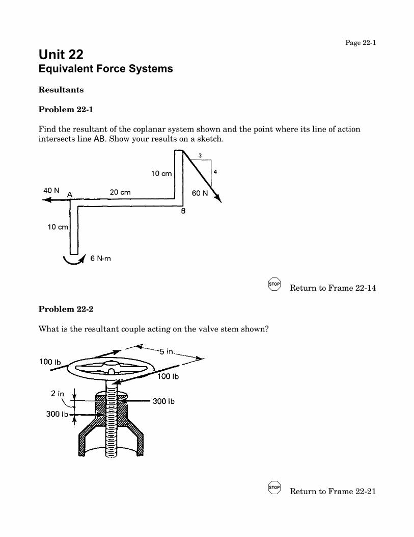
Problem 22-1
Find the resultant of the coplanar system shown and the point where its line of action intersects line AB. Show your results on a sketch.
$ Return to Frame 22-14
Problem 22-2
What is the resultant couple acting on the valve stem shown?
$ Return to Frame 22-21

Page 22-2Problem 22-3
Find the resultant of the force system shown.
$ Return to Frame 22-28

Page 22-3Problem 22-4
A square concrete foundation slab supports three columns as shown. The columns carry the loads shown. Determine the resultant load and locate the point at which its line of action passes through the foundation. Show your answer on the sketch.
$ Return to Frame 22-29

Page 22-4Problem 22-5
The figure represents a brace and bit. At the instant shown it is in the horizontal xz plane and the x-axis coincides with the bit. Find an equivalent force system consisting of a force through the "business end" of the bit and a couple.
$ Return to Frame 22-35

Page 22-5Summary of Resultants
(1.) The resultant of a concurrent force system is a _________________________ , acting
through the _________________________________________________________ .
(2.) The resultant of a system of couples is a _______________________________ .
(3.) The resultant of a system of parallel forces is a _______________________, acting
parallel to the forces of the system or a ________________________________ .
(4.) The resultant of a coplanar force system is a _______________________,
or a _________________________ .
If, in the latter two cases #F = 0 and #M0 ≠ 0, the resultant is a _________________ .
If, in the latter two cases #F ≠ 0, the resultant is a ____________________, and its
location is given by the equation ______________________________
For every general force system there is a unique equivalent system consisting of a single force and a single couple which causes rotation about an axis parallel to the force. This
system is called a _____________________________ . (22-35 and 22-36)
In any cases in which #F = 0 and #M0 = 0, the resultant is __________________, and the
body is in ______________________________ .
$ Return to Frame 22-38
Page 23-1
Unit 23Equilibrium with Couples
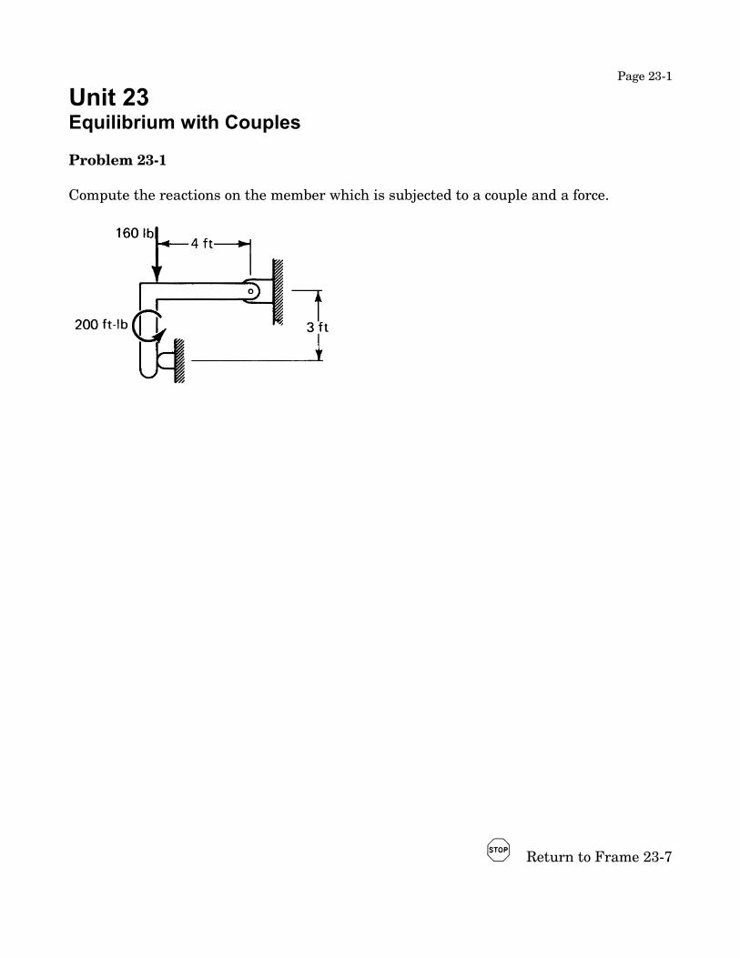
Problem 23-1
Compute the reactions on the member which is subjected to a couple and a force.
$ Return to Frame 23-7

Page 23-2Problem 23-2
The cantilever beam shown carries a load of 1500 kilograms. Find the reactions at the wall.
$ Return to Frame 23-12

Page 23-3Problem 23-3
A rope is fixed to pulley B at one end and passes over pulley A to a weight. If the torque on the shaft to which A is fastened is 30 ft-lb, what couple must be applied to B?What force does the pulley A exert on its shaft?
$ Return to Frame 23-20
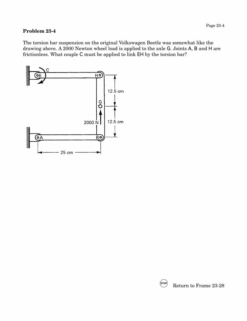
Page 23-4Problem 23-4
The torsion bar suspension on the original Volkswagen Beetle was somewhat like the drawing above. A 2000 Newton wheel load is applied to the axle G. Joints A, B and H are frictionless. What couple C must be applied to link EH by the torsion bar?
$ Return to Frame 23-28

Page 23-5Problem 23-5
The possible snow loading on the roof of a bus-stop shelter is 50 lb/ft of support. What will the reaction at the base be?
$ Return to Frame 23-34
Page 23-6Shear and Moment on a Section
The steps in finding the shear and moment on a section are:
1. ______________________________________________________
2. ______________________________________________________
3. _____________________________________________________ (23-41)
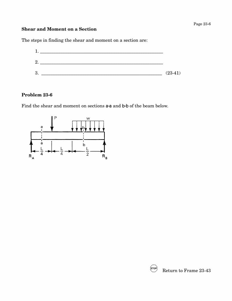
Problem 23-6
Find the shear and moment on sections a-a and b-b of the beam below.
$ Return to Frame 23-43

Page 24-1
Unit 24Introduction to Friction
Friction
Observations on Friction
Friction is the name of the force that opposes the motion of one surface relative to another. Its magnitude depends primarily on the nature of the two surfaces involved. Its direction is opposite to the motion, and is tangent to the contact surfaces. It is presumed to be caused by a tendency of the surfaces to mesh together.
Friction is either fluid friction or dry friction. The former applies not only to moving fluids but also to problems involving lubricated surfaces. The latter applies to problems involving rigid bodies in contact along non-lubricated surfaces. Since fluid friction is best considered in connection with fluid mechanics we will limit our present study to dry friction.
$ Return to Frame 24-9
There are two sorts of dry friction, static friction and kinetic friction. The first opposes impending motion; the second opposes motion actually in progress.
This course will deal only with problems involving static friction but you will encounter kinetic friction in dynamics.
Limiting friction is defined as ___________________________________________________
________________________________________________________________________ (24-11)
and implies ____________________________________________________________ (24-12)
The coefficient of friction is found by _____________________________________________
_______________________________________________________________________________
and is given by the equation ____________________________________________ (24-15)

Page 24-2
Coefficient of Static Friction
The coefficient of friction* must be determined experimentally. It is the result of the roughness or smoothness of the materials in contact. The following table shows some of the published results for common materials.
Approximate Coefficients of Static Friction for dry surfaces
Steel on steel 0.4 to 0.8
Wood on wood 0.2 to 0.5
Wood on metal 0.2 to 0.6
Metal on stone 0.3 to 0.7
Metal on leather 0.3 to 0.6
Wood on leather 0.2 to 0.5
Earth on earth 0.2 to 1.0
Cast iron on cast iron 0.3 to 0.4
Rubber on concrete 0.6 to 0.8
Rubber on ice 0.05 to 0.2
If, in practice, one needs the coefficient of friction between less common materials or under specific circumstances, he must determine it experimentally.
The coefficient of kinetic friction is also determined experimentally. For a given pair of materials it will always be than the coefficient of static friction.
* The term "coefficient of friction" will always refer to static friction throughout these units.
$ Return to Frame 24-24
f < f' implies _____________________________________________________________
f = f' implies _____________________________________________________________
f > f' implies _____________________________________________________ (24-32)

Page 24-3
List the steps in solving problems involving static friction.
1. _____________________________________________________________________________
2. _____________________________________________________________________________
3. _____________________________________________________________________________
4. _____________________________________________________________________ (24-32)
Problem 24-1
The coefficient of friction between the 300 kilogram block and the plane is 0.30. Is the 100 kilogram weight sufficient to keep the block from sliding down the plane? Prove your answer.
$ Return to Frame 24-37

Page 25-1
Unit 25Friction
Problem 25-1
The coefficient of friction between a homogeneous 300 lb block and the floor is 0.40.
Determine the maximum height above the floor at which a force sufficient to cause motion of the block will cause it to slip and not tip.
$ Return to Frame 25-13

Page 25-2Experimental Determination of Coefficient of Friction
A popular method for determining the coefficient of friction between two materials is to place a block of one material on a surface of the other and then to slowly increase the inclination of the surface until the block just begins to slide. The maximum angle at which the block remains at rest is called the "angle of repose", and this angle is carefully measured.
Free Body Diagram
#F = __________________________________
Using the equilibrium equation and designating the angle of repose as _________ , we can find the coefficient of friction from the relationship
µ = _________________________________
It is relatively easy to make precise measurements of the coefficient of friction with the method you have just studied because the measurement is a geometric one. It is very difficult to construct systems which measure the forces on the block at the instant it begins to move on a horizontal surface.
$ Return to Frame 25-16

Page 25-3Problem 25-2
What is the minimum force necessary to move the block B?
$ Return to Frame 25-24
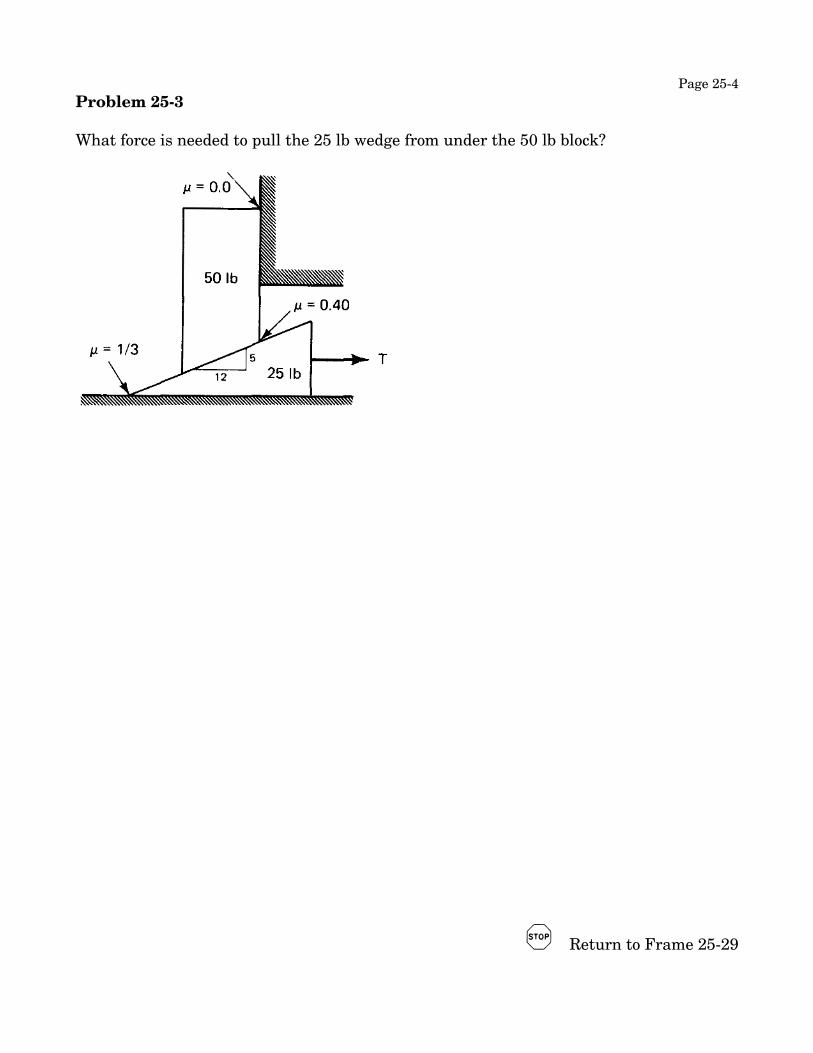
Page 25-4Problem 25-3
What force is needed to pull the 25 lb wedge from under the 50 lb block?
$ Return to Frame 25-29

Page 26-1
Unit 26Friction of Machine Elements
Problem 26-1What is the minimum value of P necessary to maintain equilibrium in the system shown?
$ Return to Frame 26-8Problem 26-2 What force must the girl exert at A on the trash can in order to move it to the right?
$ Return to Frame 26-15

Page 26-2Problem 26-3
Find the minimum value of P necessary to keep the drum from turning as a result of the application of the 300 N-m couple.
$ Return to Frame 26-19

Page 26-3Problem 26-4
Find the minimum value of P needed to move the wedge to the right. The coefficient of friction at all contact surfaces is 0.25, the cylinder weighs 1000 lb and the wedge weighs 200 lb.
(Continued on next page.)

Page 26-4Problem 26-4 (continued)
$ Return to Frame 26-29

Page 27-1
Unit 27Belt Friction
Friction on Flat Belts
Consider the case of a flexible flat belt which is wrapped around a cylinder. The angle through which the belt remains in contact with the cylinder is β and the tensions in the end portions of the belt are TL and TS as shown. Assume that TL is larger than TS , and that the belt is about to slip on the drum.
A diagram of an element of the belt which subtends an angle of dθ can be drawn as shown on the right.
$ Return to Frame 27-3 but keep your notebook open.
Summation of forces on the element gives the equations _______________________ = 0
in the x direction, and _____________________________ = 0 in the y direction.
Taking advantage of the fact that for small angles
is very much smaller than the other terms the equations may be reduced to
df = ______________ and dN = _______________
Since motion impends df = µ dN
Therefore dT = µ dT dθ
$ Return to Frame 27-8

Page 27-2The technique of separation of variables may be applied to this equation and the following definite integral established.
Evaluation of the integral yields the result
Form I. ______________ = _________________
which may also be expressed as
Form II. ______________ = _________________
Form II is the more useful and more used.
$ Return to Frame 27-13Problem 27-1
A rope is wrapped 3/4 of a turn around a fixed round bar as shown. How much force must be applied to the end of the rope to lift the 30 kilogram weight?
$ Return to Frame 27-26
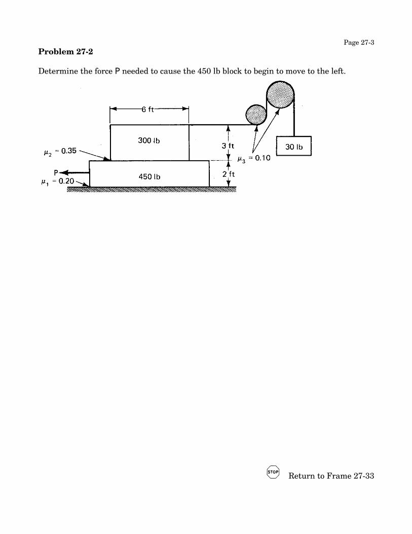
Page 27-3Problem 27-2
Determine the force P needed to cause the 450 lb block to begin to move to the left.
$ Return to Frame 27-33

Page 28-1
Unit 28Moments of Inertia of Geometric Areas
Moment of Inertia
Moment of inertia, or second moment, is the name for the commonly encountered mathematical quantity
where s is the distance to the element dA from a required axis. For example
I y = ___________ (28-10)
The element dA is always selected ____________________ to the required axis. (28-11)
The procedural steps in finding I y are:
1. _____________________________________________________________________________
2. _____________________________________________________________________________
3. _____________________________________________________________________________
4. _____________________________________________________________________________
5. _____________________________________________________________________ (28-16)
Problem 28-1
Find I y for the triangle shown.
$ Return to Frame 28-19

Page 28-2Problem 28-2
Find I x for the triangle shown. The x-axis passes through the centroid.
$ Return to Frame 28-29

Page 28-3Polar Moment of Inertia
The polar moment of inertia, J, about a point 0 is defined as
where ρ is the distance from the point to the element of area. Evaluation by means of direct integration is most efficiently accomplished by the use of polar coordinates. Fortunately there is an indirect way which is much easier.
Looking at the sketch and remembering Pythagoras we see that
Stated in words, the polar moment of inertia is equal to the sum of the moments of inertia about any two perpendicular axes which intersect at 0.
$ Return to Frame 28-33Radius of Gyration
The radius of gyration of an area with respect to an axis or point is defined physically as the distance from the axis or point at which the entire area could be concentrated without changing the moment of inertia about the axis or the point.
The mathematical definition is more to the point.
$ Return to Frame 28-40

Page 28-4

Page 29-1
Unit 29Moments of Inertia of Composite Areas
Since moment of inertia is obtained from the summation by integration of the product of a distance squared and an area, its dimensions are length2 x length x length = length4
Moments of inertia of areas are used primarily in “strength of materials” problems. Since in American engineering mechanics problems the areas involved are of a size most conveniently measured, and shown on drawings, in inches, and stresses are expressed in Pounds per square inch, the moment of inertia of an area is most commonly and usefully expressed in inches4. We will use in4 as the proper form for answers in these units in ACU.
In SI, the situation is a bit more complex. Although are often given on drawings in centimeters, in calculations meters are the correct unit. We will use m4 as the proper form for answers in these units in SI.
Moment of Inertia of Composite Areas
Moment of inertia for a composite area may be found by direct addition or subtraction of the moments of inertia of the parts as long as the moments of inertia of the parts are all known about the desired axis.
Problem 29-1
Use subtraction to find I x and I y for the scalene triangle shown.
$ Return to Frame 29-11

Page 29-2Parallel Axis Theorem
The parallel axis theorem enables us to find the moment of inertia of an area about any axis in terms of a parallel axis passing through the centroid of the area. It is most conveniently expressed in terms of the transfer equation
I xa = ________________________
In this equation I xa is ______________________________________ ,
I xG is __________________ , and d is _________________________________________ .
Problem 29-2
The circle is 4 centimeters in diameter. Find I y
The transfer equation may also be used in reverse to find I xG if the moment of inertia is known about any x-axis.
Problem 29-3
Find I xG for the semi-circle by use of the transfer equation.
Complete the table on page 28-4 and return to Frame 29-24.

Page 29-3Choice of Reference Axis
There is no right or wrong reference axis. There are, however, axes that result in easier work than others.
Easy work usually results from an axis chosen according to one or more of the following criteria:
(1.) _____________________________________________________________________ (29-34)
(2.) ______________________________________________________________________ (29-36)
(3.) ______________________________________________________________________ (29-36)
(4.) ______________________________________________________________________ (29-37)
(5.) ______________________________________________________________________ (29-38)
Problem 29-4
Find the moment of inertia about a horizontal axis through the centroid (I xG) for the area shown. I'll leave it to you to practice drawing the table this time.
$ Return to Frame 29-40

Page 30-1
Unit 30Moments of Inertia of Mass
The moment of inertia of a mass, of density δ , is given by the integral
I = ________________________________________________________________ (30-3)
In selecting the element it is necessary to exercise care that the entire element be a constant distance from the axis in question. This generally results in a multiple integration, for which the best reference is a calculus book.
As you work through this unit you will record the results of evaluating the integrals for several common engineering shapes on the following page.

Page 30-2Moment of Inertia of Geometric Shapes
Cylinder about its geometric axis.
I z =
Thin disk about a diametric-axis through the mass center.
I y =
Cylinder about a diametric-axis through the mass center.
I x =
Rectangular parallelepiped about an axis parallel to a longitudinal face and passing through the mass center.
I x =
Slender rod of any cross-section about an axis perpendicular to the longitudinal axis and passing through the mass center.
I x =
Sphere about any axis through its mass center.
$ Return to Frame 30-26
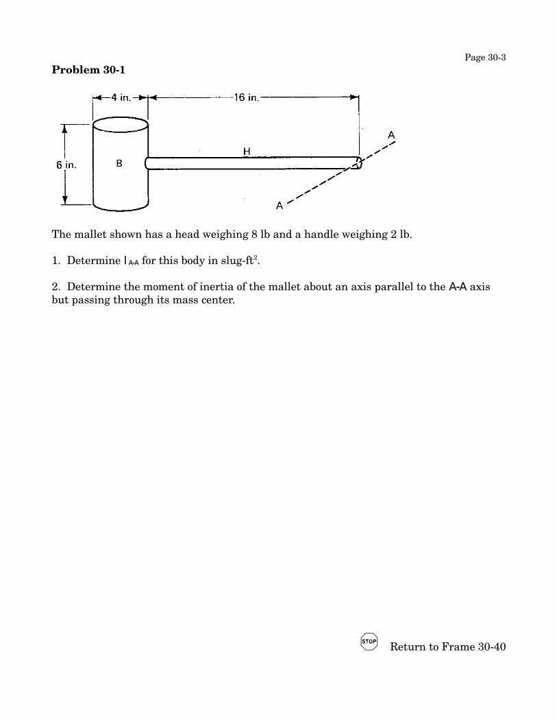
Page 30-3Problem 30-1
The mallet shown has a head weighing 8 lb and a handle weighing 2 lb.
1. Determine I A-A for this body in slug-ft2.
2. Determine the moment of inertia of the mallet about an axis parallel to the A-A axis but passing through its mass center.
$ Return to Frame 30-40
Page 30-4
Radius of Gyration
The radius of gyration of a mass about a given axis is defined as _____________________
_________________________________________________________________________________
It is calculated from the equation k = __________________________ (30-41)
Problem 30-2
Find the radius of gyration of the body in Problem 30-1 about an axis through the mass center parallel to A-A.
k G = _______________
Find the radius of gyration of the body about A-A.
k A-A = ______________

Page 30-5Problem 30-3
The roly-poly shown has a mass of 1 kilogram and a radius of gyration of 8 centimeters about its mass center. What is its moment of inertia about an axis through its mass center?
$ Return to Frame 30-50