+p4p800 se front matterdlsvr04.asus.com/pub/asus/mb/sock478/p4p800-se/t1535_p4p800-se.pdf · modem...
TRANSCRIPT

Mot
herb
oardP4P800 SE

2
T1535
© 2004

3
4

5

6
®

7
•
•
•
•
•
•
•
•
•
•
•
•

8
•
•
•
•
•

9
™
Jumper Free(Default)
2 3
Jumper Mode
1 2

10
P4P800 SE-TAYZ
10839 110366 011XX11XX11

11
® ®
®
®
®
®
®

12


1-1
®
®

1-2
®
®
®
®

1-3

1-4

1-5

1-6


2-1
P4P800 SE
®
P4P800 SE Onboard LED
SB_PWR1
ONStandbyPower
OFFPowered
Off

2-2

2-3
PANEL1
P4P800 SE
®
CD1
AUX1
CPU_FAN1
FP_AUDIO
GAME1
Socket 478
ATX12V1
CHASSIS1
CLRTC1
COM1
SPDIF_O
SPDIF_OUT
KBPWR
CHA_FAN1
SATA2
COM2
USB_56 USB_78
SB_PWR1
PWR_FAN1
SATA1
MODEM1
WIFI
USBPW12USBPW34
USBPW56USBPW78
24.5cm (9.6in)
30.5
cm (
12.0
in)
SMB20
USB2.0
USB20_12

2-4

2-5

2-6
® ®
®
®
®

2-7
®
90 - 100

2-8
®
®
®

2-9
®
®
®
®
®

2-10

2-11

2-12
P4P800 SE
®
P4P800 SE 184-Pin DDR DIMM Sockets80
Pin
s10
4 P
ins
DIM
M_A
1
DIM
M_A
2
DIM
M_B
1
DIM
M_B
2

2-13
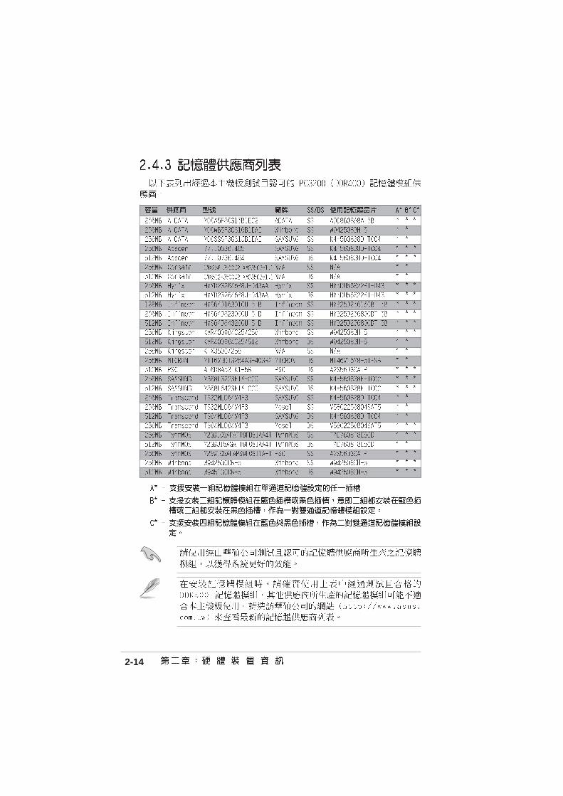
2-14

2-15

2-16

2-17
A B C D E F G H

2-18
P4P800 SE
®
P4P800 SE Accelerated Graphics Port (AGP)
Keyed for 1.5v

2-19
P4P800 SE
®
P4P800 SE WIRELESS Connectors
WIFI

2-20
P4P800 SE
®
P4P800 SE Clear RTC RAM
CLRTC1
Normal Clear CMOS(Default)
1 2 2 3

2-21
P4P800 SE
®
P4P800 SE USB Device Wake Up
3221
+5V(Default)
+5VSB
USBPW12USBPW34
3221
+5V(Default)
+5VSB
USBPW56USBPW78

2-22
P4P800 SE
®
P4P800 SE Keyboard Power Setting
(Default)+5V +5VSB
KBPWR2 31 2
P4P800 SE
®
P4P800 SE SMB2.0 Support
SMB20
DisableEnable(Default)
3221

2-23
1
11
4
5
6
7
2 3
910 8

2-24

2-25
P4P800 SE
®
P4P800 SE IDE Connectors
SE
C_I
DE
1
PR
I_ID
E1
PIN 1
P4P800 SE
®
P4P800 SE Floppy Disk Drive Connector
PIN 1
FLOPPY1

2-26
•
•
•
•
P4P800 SE
®
P4P800 SE SATA Connectors
SATA2
GN
DR
SAT
A_T
XP
2R
SAT
A_T
XN
2G
ND
RS
ATA
_RX
P2
RS
ATA
_RX
N2
GN
D
SATA1
GN
DR
SAT
A_T
XP
1R
SAT
A_T
XN
1G
ND
RS
ATA
_RX
P1
RS
ATA
_RX
N1
GN
D

2-27
2-28
P4P800 SE
®
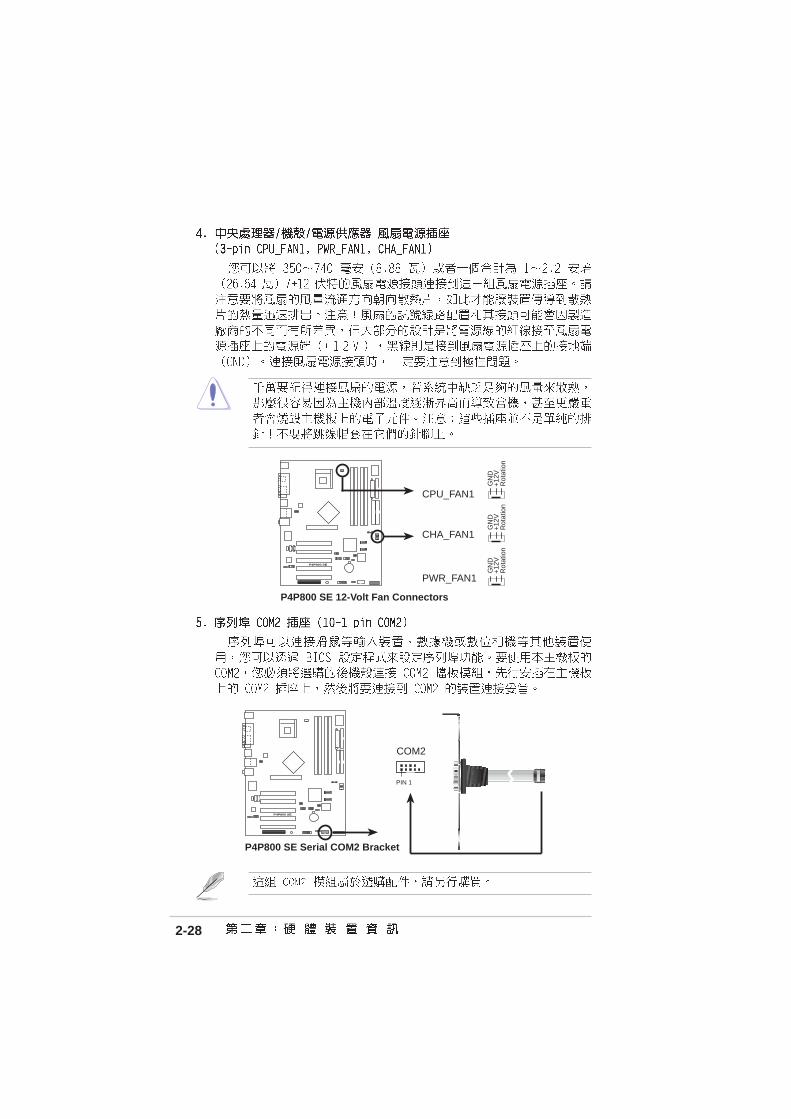
P4P800 SE 12-Volt Fan Connectors
CPU_FAN1
CHA_FAN1
GN
D
Rot
atio
n+
12V
PWR_FAN1
GN
D
Rot
atio
n+
12V
GN
D
Rot
atio
n+
12V
P4P800 SE
®
P4P800 SE Serial COM2 Bracket
PIN 1
COM2

2-29
P4P800 SE
®
P4P800 SE ATX Power Connector
ATXPWR1 ATX12V1
+3.3VDC-12.0VDC
COMPS_ON#
COMCOM
COM-5.0VDC+5.0VDC+5.0VDC
PWR_OK
+12.0VDC
+3.3VDC+3.3VDCCOM
+5.0VDCCOM+5.0VDC
COM
+5VSB
+12V DC GND
+12V DC GND
2-30
P4P800 SE
®
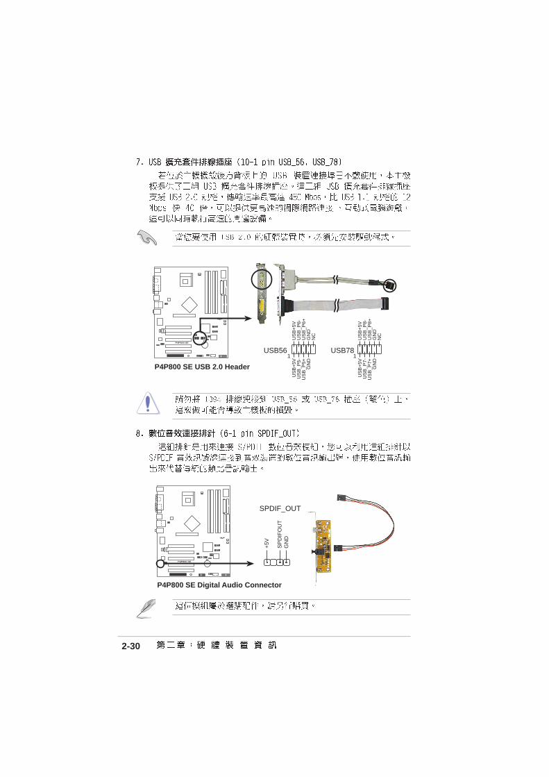
P4P800 SE USB 2.0 Header
USB56
US
B+
5VU
SB
_P6-
US
B_P
6+G
ND
NC
US
B+
5VU
SB
_P5-
US
B_P
5+G
ND
1USB78
US
B+
5VU
SB
_P8-
US
B_P
8+G
ND
NC
US
B+
5VU
SB
_P7-
US
B_P
7+G
ND
1
P4P800 SE
®
P4P800 SE Digital Audio Connector
+5V
SP
DIF
OU
TG
ND
SPDIF_OUT

2-31
P4P800 SE
®
P4P800 SE Internal Audio Connectors
CD1(Black) AUX1(White)
Right Audio Channel
Left Audio ChannelGroundGround
MODEM
Modem-InGround
Modem-OutGround
P4P800 SE
®
P4P800 SE Front Panel Audio Connector
FP_AUDIO
BLI
NE
_OU
T_L
MIC
2
Line
out
_R
Line
out
_L
BLI
NE
_OU
T_R
NC
MIC
PW
R+
5VA
AG
ND

2-32
P4P800 SE
®
P4P800 SE Game Connector
GAME1+
5V+
5VJ2
B1
J2C
XM
IDI_
OU
TJ2
CY
J2B
2M
IDI_
IN
J1B
1J1
CX
GN
DG
ND
J1C
YJ1
B2
+5V
P4P800 SE
®
P4P800 SE Chassis Alarm Lead
CHASSIS1
+5V
SB
_MB
Cha
ssis
Sig
nal
GN
D
(Default)

2-33
P4P800 SE
®
P4P800 SE System Panel Connectors* Requires an ATX power supply.
PLE
D-
Gro
und
PW
R+
5V Spe
aker
SpeakerConnectorPower LED
Gro
und
Reset SW
SMI Lead
Ext
SM
I#
Gro
und
Res
etG
roun
dG
roun
d
ATX PowerSwitch*
PLE
D+
IDE
_LE
D-
IDE
_LE
D+
IDE_LED
•
•
•
•
•

2-34
•


3-1

3-2


4-1

4-2
A:\>afudos /iP4P800SE.rom
AMI Firmware Update Utility - Version 1.10
Copyright (C) 2002 American Megatrends, Inc. All rights reserved.
Reading file ..... done
Erasing flash .... done
Writing flash .... 0x0008CC00 (9%)
4-3
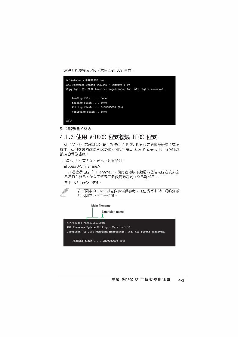
A:\>afudos /iP4P800SE.rom
AMI Firmware Update Utility - Version 1.10
Copyright (C) 2002 American Megatrends, Inc. All rights reserved.
Reading file ..... done
Erasing flash .... done
Writing flash .... 0x0008CC00 (9%)
Verifying flash .. done
A:\>
Main filename
Extension name
A:\>afudos /oMYBIOS03.rom
AMI Firmware Update Utility - Version 1.10
Copyright (C) 2002 American Megatrends, Inc. All rights reserved.
Reading flash ..... 0x0008CC00 (9%)

4-4
User recovery requested. Starting BIOS recovery...
Checking for floppy...
•
•
A:\>afudos /oMYBIOS03.rom
AMI Firmware Update Utility - Version 1.10
Copyright (C) 2002 American Megatrends, Inc. All rights reserved.
Reading flash ..... done
A:\>

4-5
User recovery requested. Starting BIOS recovery...
Checking for floppy...
Floppy found!
Reading file “P4P800SE.rom”. Completed.
Start flashing...
Flashed successfully. Rebooting.
Bad BIOS checksum. Starting BIOS recovery...
Checking for floppy...

4-6
Bad BIOS checksum. Starting BIOS recovery...
Checking for floppy...
Bad BIOS checksum. Starting BIOS recovery...
Checking for floppy...
Floppy not found!
Checking for CD-ROM...
CD-ROM found.
Reading file “P4P800SE.rom”. Completed.
Start flashing...
Bad BIOS checksum. Starting BIOS recovery...
Checking for floppy...
Floppy found!
Reading file “P4P800SE.rom”. Completed.
Start flashing...

4-7

4-8

4-9

4-10
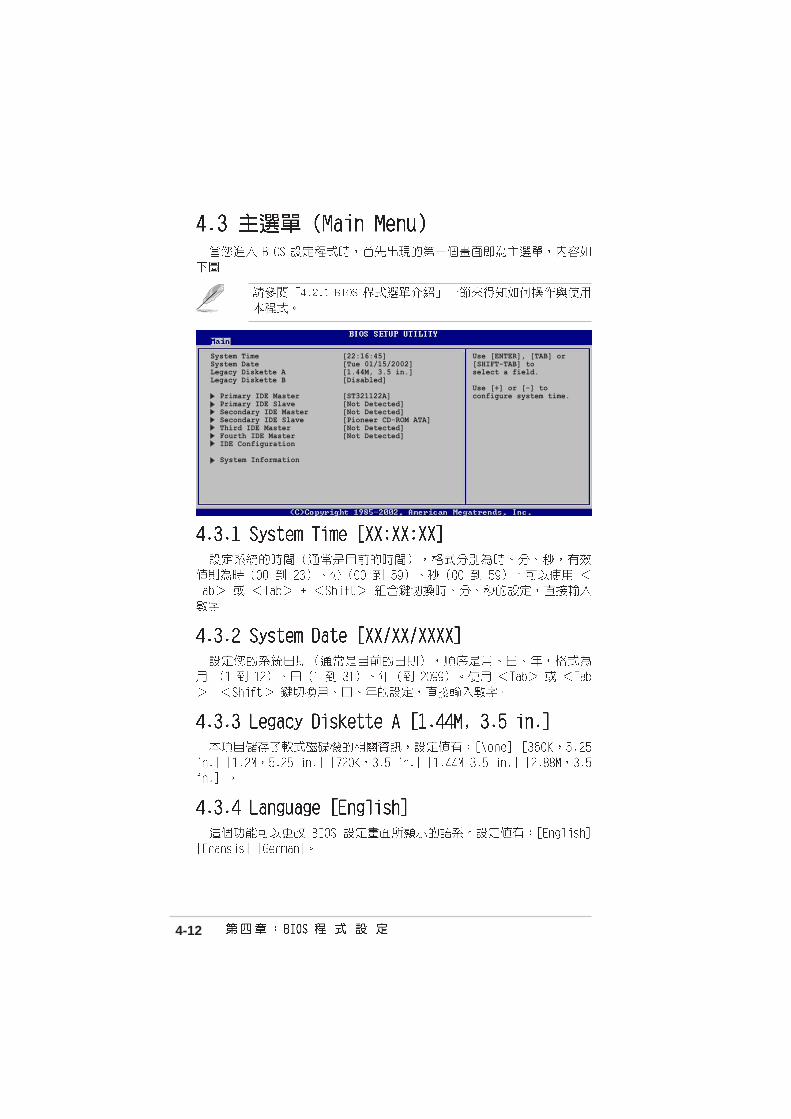
System Time [22:16:45]System Date [Tue 01/15/2002]Legacy Diskette A [1.44M, 3.5 in.]Legacy Diskette B [Disabled]
Primary IDE Master [ST321122A]Primary IDE Slave [Not Detected]Secondary IDE Master [Not Detected]Secondary IDE Slave [Pioneer CD-ROM ATA]Third IDE Master [Not Detected]Fourth IDE Master [Not Detected]IDE Configuration
System Information
Use [ENTER], [TAB] or[SHIFT-TAB] toselect a field.
Use [+] or [-] toconfigure system time.

4-11
4-12
System Time [22:16:45]System Date [Tue 01/15/2002]Legacy Diskette A [1.44M, 3.5 in.]Legacy Diskette B [Disabled]
Primary IDE Master [ST321122A]Primary IDE Slave [Not Detected]Secondary IDE Master [Not Detected]Secondary IDE Slave [Pioneer CD-ROM ATA]Third IDE Master [Not Detected]Fourth IDE Master [Not Detected]IDE Configuration
System Information
Use [ENTER], [TAB] or[SHIFT-TAB] toselect a field.
Use [+] or [-] toconfigure system time.

4-13
Primary IDE Master
Device : Hard DiskVendor : ST32122ASize : 2.1GBLBA Mode : SupportedBlock Mode : 16SectorsPIO Mode : 4Async DMA : MultiWord DMA-2Ultra DMA : Ultra DMA-2SMART Monitoring: Supported
Type [Auto]LBA/Large Mode [Auto]Block (Multi-sector Transfer) M[Auto]PIO Mode [Auto]DMA Mode [Auto]SMART Monitoring [Auto]32Bit Data Transfer [Disable]
Select the type ofdevice connected to thesystem.

4-14
IDE Configuration
Onboard PCI IDE Operate Mode [Enhanced Mode] Enhanced Mode Support On [S-ATA] Configure S-ATA as RAID [No]IDE Detect Time Out (Sec) [35]
Set [Compatible Mode]when Legacy OS (i.e.WIN ME, 98, NT4.0, MSDOS) is used.
Set [Enhanced Mode]when Native OS (i.e.Win2000, WIN XP) isused.

4-15

4-16
AMI BIOSVersion : 1001.004Build Date : 01/27/04
ProcessorType : Intel(R) Pentium(R) 4 Family CPU 2.40GSpeed : 2400MHzCount : 1
System MemorySize : 128MB
JumperFree ConfigurationCPU ConfigurationChipsetOnboard Devices ConfigurationPCIPnPUSB ConfigurationSpeech ConfigurationInstant Music Configuration
Adjust systemfrequency/voltage.

4-17
Configure System Frequency/Voltage
AI Overclock Tuner [Standard]
Performance Mode [Auto]
Select the target CPUfrequency, and therelevant parameters willbe auto-adjusted.Frequencies higher thanCPU manufacturerrecommends are notguaranteed to be stable.If the system becomesunstable, return to thedefault.

4-18
Configure System Frequency/Voltage
AI Overclock Tuner [Manual]CPU External Frequency (MHz) [133]DRAM Frequency [Auto]AGP/PCI Frequency (MHz) [Auto]
CPU VCore Voltage [Auto]DDR Reference Voltage [Auto]AGP VDDQ Voltage [1.50V]
Performance Mode [Auto]
Select the target CPUfrequency, and therelevant parameterswill be auto-adjusted.Frequencies higherthan CPU manufacturerrecommends are notguaranteed to be stable.If the system becomesunstable, return to thedefault.

4-19
Configure advanced CPU settings
Manufacturer : Intel(R)Brand String : Intel(R) Pentium(R) 4 Family CPU 2.4GFrequency : 2400MHzFSB Speed : 533MHz
Cache L1 : 8 KBCache L2 : 512 KBCache L3 : 0 KB
Ratio Status : LockedRatio Actual Value : 18 VID CMOS Setting: [ 62]Maximum Value Limit [Disabled]CPU Internal Thermal Control [Auto]
Selects the VIDsetting at whichthe processor isto run.

4-20
Advanced Chipset settings
WARNING: Setting wrong values in the sections below may cause system to malfunction.
Configure DRAM Timing by SPD [Enabled]Memory Acceleration Mode [Auto]DRAM Idle Timer [Auto]DRAM Refresh Rate [Auto]
Graphic Adapter Priority [AGP/PCI]Graphics Aperture Size [ 64MB]Spread Spectrum [Enabled]
ICH Delayed Transaction [Enabled]
MPS Revision [1.4]
Set DRAM timingparameters accordingto DRAM SPDor manually.

4-21

4-22
®
OnBoard AC’97 Audio� [Auto]OnBoard LAN [Enabled] OnBoard LAN Boot ROM [Disabled]
Serial Port1 Address [3F8/IRQ4]Serial Port2 Address [2F8/IRQ3]Parallel Port Address [378]Parallel Port Mode [ECP] ECP Mode DMA Channel [DMA3] Parallel Port IRQ [IRQ7]OnBoard Game/MIDI Port [Disabled]

4-23

4-24
PCI Slot-1/5 IRQ Preference [Auto]PCI Slot-2 IRQ Preference [Auto]PCI Slot-3 IRQ Preference [Auto]PCI Slot-4 IRQ Preference [Auto]
NO: Lets the BIOSconfigure all thedevices in the system.YES: Lets theoperating systemconfigure Plug andPlay (PnP) devices notrequired for boot ifyour system has a Plugand Play operatingsystem.
Advanced PCI/PnP settings
WARNING: Setting wrong values in the sections below may cause system to malfunction.
Plug and Play OS [No]PCI Latency Timer [64]Allocate IRQ to PCI VGA [Yes]Palette Snooping [Disabled]PCI IDE BusMaster [Enabled]
IRQ3 [Available]IRQ4 [Available]IRQ5 [Available]IRQ7 [Available]IRQ9 [Available]IRQ10 [Available]IRQ11 [Available]IRQ14 [Available]IRQ15 [Available]

4-25
USB Configuration
Module Version - 2.23.0-4.3
USB Devices Enabled : None
USB Function [8 USB Ports]Legacy USB Support [Auto]USB 2.0 Controller [Enabled]USB 2.0 Controller Mode [HiSpeed]
USB Mass Storage Device Configuration
Enables USB hostcontrollers.

4-26
USB Mass Storage Device Configuration
USB Mass Storage Reset Delay [20 Sec]
No USB Mass Storage device detected
Number of secondsPOST waits for the USBmass storage deviceafter the start unitcommand.

4-27
Instant Music Option
Instant Music [Disabled]
If enabled, power upby PS/2 kepyboardfunction will bedisabled.

4-28
Suspend Mode [Auto]Repost Video on S3 Resume [No]ACPI 2.0 Support [No]ACPI APIC Support [Enabled]
APM ConfigurationHardware Monitor
Select the ACPI stateused for SystemSuspend.

4-29
APM Configuration
Power Management/APM [Enabled]Video Power Down Mode [Suspend]Hard Disk Power Down Mode [Suspend]Suspend Time Out [Disabled]Throttle Slow Clock Ratio [50%]
Power Button Mode [On/Off]Restore on AC Power Loss [Power Off]
Power On By RTC Alarm [Disabled]Power On By External Modems [Disabled]Power On By PCI Devices [Disabled]Power On PS/2 Keyboard [Disabled]Power On PS/2 Mouse [Disabled]
Enable or disableAPM.

4-30

4-31
Hardware Monitor
CPU Temperature [31.5°C/86.5°F]MB Temperature [31°C/87.5°F]Power Temperature [N/A]
Q-Fan Control [Disabled]
CPU Fan Speed [5232RPM]Chassis Fan Speed [N/A]Power Fan Speed [N/A]
VCORE Voltage [1.552V]3.3V Voltage [3.408V]5V Voltage [5.080V]12V Voltage [11.977V]
CPU Temperature

4-32
Boot Settings
Boot Device Priority
Boot Settings ConfigurationSecurity
Specifies the BootDevice Prioritysequence.

4-33
Boot Device Priority
1st Boot Device [1st Floppy Drive]2nd Boot Device [PM-ST32122A]3rd Boot Device [SS-Pioneer CD-ROM]4th Boot Device [Yukon PXE]
Specifies the bootsequence from theavailable devices.
A device enclosed inparenthesis has beendisabled in thecorresponding typemenu.
Boot Settings Configuration
Quick Boot [Enabled]Full Screen Logo [Enabled]Add On ROM Display Mode [Force BIOS]Bootup Num-Lock [On]PS/2 Mouse Support [Auto]Boot to OS/2 [No]Wait for ‘F1’ If Error [Enabled]Hit ‘DEL’ Message Display [Enabled]Interrupt 19 Capture [Disabled]
Allows BIOS to skipcertain tests whilebooting. This willdecrease the timeneeded to boot thesystem.

4-34

4-35
Security Settings
Supervisor Password :Not InstalledUser Password :Not Installed
Change Supervisor Password
Boot Sector Virus Protection [Disabled]
<Enter> to changepassword.<Enter> again to disablepassword.

4-36
Security Settings
Supervisor Password InstalledUser Password Not Installed
Change Supervisor PasswordUser Access Level [Full Access]Change User PasswordClear User PasswordPassword Check [Setup]
Boot Sector Virus Protection [Disabled]
<Enter> to changepassword.<Enter> again to disablepassword.

4-37
Exit Options
Exit & Save ChangesExit & Discard ChangesDiscard Changes
Load Setup Defaults
Exit system setup aftersaving the changes.
F10 key can be used forthis operation.
4-38


®

5-1

5-2
®

5-3

5-4

5-5

5-6

5-7

5-8
5-9

5-10
Esc F1 F2 F3 F5 F6 F7 F8F4

5-11

5-12
•
•

5-13

5-14

5-15

5-16

5-17
®
®
®
®
®
®
®
•
•

5-18
[ HELP ]
�
Enter a string between 1 and 16 characters in length taht can be usedto uniquely identify the RAID volume. This name is case sensitive and
can not contain special characters.
Copyright(C) 2003 Intel Corporation. All Rights Reserved. v3.x.x.xxxx
[ CREATE ARRAY MENU ]
Name: RAID_Volume1RAID Level: RAID0(Stripe)Strip Size: 128KB Capacity: 149.0GB
�� Create Volume
[ ]-Change�[ ]-Change� [TAB]-Next�[TAB]-Next� [ESC] Previous Menu��[ESC] Previous Menu�� [Enter]-Select[Enter]-Select
[ DISK/VOLUME INFORMATION ]
�
��
RAID Volumes:None defined.
Non-RAID Disks:Port Drive Model�� Serial #�� Size�� Status�� Bootable 0 ST320413A��� xxxxxxxx�� 18.6GB� Normal�� Yes 1 ST320413A��� xxxxxxxx�� 18.6GB� Normal�� Yes
Intel(R) Integrated RAID for Serial ATA - RAID Configuration UtilityCopyright(C) 2003 Intel Corporation. All Rights Reserved. v3.x.x.xxxx
[ MAIN MENU ]
1.� Create RAID Volume2.� Delete RAID Volume3.� Reset Disks to Non-RAID4.� Exit
[ ]-Select��[ ]-Select�� [ESC] Exit��[ESC] Exit�� [Enter]-Select Menu[Enter]-Select Menu

5-19
•••
Are you sure you want to create this volume (Y/N)
[ HELP ]
�
Deleting a volume will destroy the volume data on the drive(s) andcause any member disks to become available as non-RAID disks.
WARNING:�EXISTING DATA WITHING THIS VOLUME WILL BE LOST AND NON-RECOVERABLE
Copyright(C) 2003 Intel Corporation. All Rights Reserved. v3.x.x.xxxx
[ DELETE ARRAY MENU ]
[ ]-Change�[ ]-Change� [TAB]-Next�[TAB]-Next� [<ESC>]-Previous Menu�[<ESC>]-Previous Menu� [<DEL>]-Delete Volume[<DEL>]-Delete Volume
Name��� Level�� Drives � Capacity� Status�� BootableRAID_Volume1� RAID0(Stripe)� 2�� 149.0GB�Normal�� Yes

5-20
Are you sure you want to delete this volume?ALL DATA IN THE VOLUME WILL BE LOST!!
Are you sure you want to delete volume "RAID_Volume1"? (Y/N)
[ VOLUME DELETE VERIFICATION ]
[ DISK/VOLUME INFORMATION ]
�
RAID Volumes:None defined.
Non-RAID Disks:Port Drive Model�� Serial #�� Size�� Status�� Bootable 0 ST380013AS�� xxxxxxxx�� 74.5GB� Normal�� Yes 1 ST380013AS�� xxxxxxxx�� 74.5GB� Normal�� Yes
Copyright(C) 2003 Intel Corporation. All Rights Reserved. v3.x.x.xxxx
[ MAIN MENU ]
1.� Create RAID Volume2.� Delete RAID Volume3.� Reset Disks to Non-RaID4.� Exit
[ ]-Select��[ ]-Select�� [ESC] Exit��[ESC] Exit�� [Enter]-Select Menu[Enter]-Select Menu
Resetting all RAID data will remove any internal RAID structuresfrom all RAID disks, including disks with working volumes. Thesestructures are used to maintain the RAID volumes. By removingthese structures, the drive will revert back to a Non-RAID diskthat can then be used or reallocated to a new RAID volume.
[ RESET ALL DATA RAID DATA ]
WARNING: Selecting "Yes" will cause all data on any RAID disk(RAID Volume or Other RAID Disk) to be lost.
Are you sure you want to destroy all RAID data (Y/N):

5-21
®
®

5-22
