owner's - richard j anderson
TRANSCRIPT

OWNER'S
.JENSEN MARINE CORPORATION
ANT PLEASE READ

,
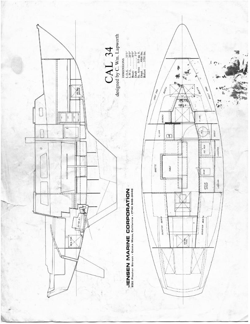
OWN ER t S GUIDE - CAL- 34
We l come i nto t he fast- gr owi ng owner's group of J ensen Fiberglas s Yachts ! Your CAL- 34 has been carefully eng i neered and bui lt to require a mini mum of maintenance and a maximum of sailing pleasure . To insure th is , the foll owing i s a description of t he operational check s and tasks normally deal t wi th by the owner to ma i n t ain his CAL- )4.
Le t 's become acqua int ed with these various operations by preparing a CAL-}4 for a day's sal1 and discuss i ng t he maintenance r out ine which you should fo l low. It 111. good prac t ice t o close the Fue l Shut - ofr Valve and al l Sea Cocks, except two, when leaving your boat , espec ially for ext ended perlod.s of time. The "coming on board" and t h e opening of t h ese fl ttings s tarts our "Sai ling Check- off Lis t ."
I . TANKAGE
A 25 gallon regular gal!! tank is located under the cockpit 150le fill cap and ventI!! aft in the port winch island . The Fuel Shut - off Valve il5 on the's forward s t arboard I!!ide and il5 reached via an access the s t arboard quarter berth. When t he handle is the fuel line it is OPEN, at right angles, it is not operati ng the engine , this valve shoul d remain A partially filled gas tank oan cause water condensation, s msjor CII.USP. of sticky valves. To aVOid thi s, we recommend keeping the t ank full and the carburetor bowl clean.
A 21 gal lon fresh water tank is under the forward double bert h. The tank fi l l, a bronze plU8 with a ; inch equare recess, is on t he aft end and the vent is in the forepeak .
II . SEA COCKS
All thru_hull f ittings, except the optional speed indicator, are equipped with gate valve s . To OPEN, turn oounterclockwise , to CLOSE , turn clockw1 ee. Following i8 the location and function of these valves , starting with the two which r emain OPEN at all times.
A. COCKPIT SCUPPERS, port and etar board
Theee two It'' valves are on either Side of the engine and must r emain open at all times t o keep ~e cockpit dry. Both valves can be reached by removing the main companionway l adder . Once a month , 0108e and re- open these valves to keep them in working order. At this time , oheok the packing glands on ALL gate valves to avoid water eeepage.

3. ;::Na !!IE COOLI NG WATER IHTAKE
Located under the cabin ~ole at the foo t of the main companionway ladder , this t " valve mus t be open when the engine is running . Water ln t he bilge? Our fiberelass hull ls water t i ght but the ice box drains into the bilge! Also there could be 80me seepage from the thru- hull fit tings and there should be a little from the propeller shaft packing gland . The optional Hand Bilge Pump is in t he battery COmpartment under the aft settee seat.
C. GALLEY SINK AND LAVATORY DRAINS
There are 3/4" valves below both sinks. These valves should be kept closed while sailing as excessive heel could fill the sinks and splash water into the interior. If you have equipped your CAL-}4 with an optional Depth Indicator Box, it is l ocat ed below the head sink.
D. MARINE TOILET WATER INTAKE AND DISCHARGE
The 1" Water Intake Valve is located in the forward starboard. hanging lOCker while the l~" Dilcharge Valve is directly behind the bowl. They may be kept open while sailing with no ill effects assuming the intemal "Joker" valve is not held open by refuse .
III. ENGINE
Operation proc edures are well covered in ths snclosed manual . Seversl import ant points should be re- emphasized .
A. Turn the Maln Battery SWi t ch , l ocat ed t o port of the main companionway ladder, to the position you have deaignated aa the engine battery. When the engine is IDLING, you r.I8y switch from one battery to another for charging . NEVER pas8 through the "OFF " po8 ition when the engine i 8 running or the Altemator Diodes will be burned out. If both batteries are of equal charge , keep selector switch in "ALL" positi on . This position is also used to start t he engine when both batteries are low. Nben not operating the 8ngine , use one battery for ship's gear , thus saving the s&oond battery for starting the engine.
B. Run the Blower fiVe minutes prior to starting the engine. Switch is on the main instrument panel in the starboard oockpit 8eat locker while the blower disoharges out thru the port transo~ deck vent.
C. Remove the Main Companionway Ladder. Check:
1. Keep the Engine Oil Level be t ween the #1 and #2 marks on the Bayonet Oil Gauge . Oil should be changed every forty to fifty operating hoUl's with three to four quarts of SAE 1130 ''lLD.'' detergent oil. Havol1ne i s
- 2-

• •
recommended by the manufacturer. After 1966 , the built- in hand sump p~~p was r eplaced by a separate hand sump pump.
2. Periodically add 011 to the Dis t ributor Cup and tighten the Vater Pump Grease Cap.
). The Carburetor Fuel Bowl may have to be fllled using the hand primer on the ruel pump.
4. 011 1n the V_Drive Box should be changed atter the first fif ty hours and every 500 hours thereafter . Clean the magnetic drain plug at this time. Less than a one pound can of "Lubrlp!ate APG- 80" or the equivalent will fill the box. No t e the dip stick on the port side and the rubber hoses leading 1n and out. The main engine sea wat er ciroulating system cools the V-Dri ve prior to ita entering the englne.
5 . Prope ller Shaft Packing Gland 18 directly under the transmission and should be damp. Tighten the nute snug enough to eliminate any exceesive water drips.
D. Pl ace Shif t Lever into the large diameter ring of the Morse Control Head on the starboard cockpit seat riser. Start engine with l ever in Vertical or NEUTRAL poeition . Lever FORWARD ie FORWARD, AFT is REVERSE.
E. Place Throttle Lever into the Notched Control Head and advance about 450 to start engine. Note that the throttle may be adjusted without the lever by grasping the notChed control head and turning to the desired setting. Additional informat i on on the Moree Control Unit has been included for your convenience.
P. Water and fuel lines OPEN?
O. Pull out Ignition Switch and Choke. Preee Starter Button. When engine starte:
1. Gradually push in Choke.
2. Adjust throttle to idling epeed.
} . Cheok Oi l Preseure: }O t o }5 pounds on a oold engine.
4 . Cool i ng Syetem is opera ting only if water ie coming out of Exhauat Outlet 1n t r aneom.
5 . If oil preeeure 1e low, STOP the engine and oheok 011 level.
6. I f water doe8 not beg1n to flow out the t ransom outlet w1thin } or 4 m1nutes , STOP the engine and check water intake valve.
- ) -

• •
I
IV.
H.
I.
1. Turn off Blower.
Run engine at Idle when shifting into forward or reverse. I f equipped with a Martec Prop, (R1ght Hand, 16" x I} x l " ) please follow the 1nstructions 1n the Appendix . . It half throttle the CAL-JU 10'111 power around 6. 5 knots using about one gallon of ruel per hour. In smooth water, higher speeds can be obtained with higher RPM's but f uel conaumpt i on 10'111 increase accordingly.
To Shut Down eng1ne:
1. Push IN Ignition Switch.
2. Close Fuel Shut- ofr Valve and Cooling Water Intake Gate Valve.
,. Mark and al1gn Propell er Shai' t for Sa1l1ng POllit1cn and ehlf't into FORWARD to lock. Wi th a standard. two blade 8011d or feathering prop . the blades should be vertical. With a fold 1ng prop , the blades should be horizontal.
GALLEY
The Water System and S1nk Drain have been oovered earlier. Mention was also made that the 50 pound Ice Box drains into the bilge. A 2 or 3 burner Pressure Alcohol Stove is the normal optional installation so we have included operating instructions in the Appendix. A few additional points on stove operation are important.
The optional 2 gallon pressure tank is located behind the galley sink. When f111ing this tank, please observe the following BEFORE removing the stopper:
1. All burners are OFF.
2. Main Aloohol Shut - off Valve on top Of pressure tank is CLOSED.
3 . Tank pressure is ZERO: Remove Stopper,
4. Pill the tank three -quarters full to allow for air pressure.
5· Replace stopper and screw down tight.
6 . Experience has shOwn that 5 pounds of tank preeeure ia more than adequate and imposes l eas strain on the fittings than ths recommended 10 pounds.
V. HEAD
Operating instructions for the Marine TOilet are 1nclosed
-4-

• <
but additional in f ormation and replacemen t parta can be obt ained from the manui'acturer .
Don't f or ge t the earl leI' Gate Valve ins truct i ons!
VI . ELECTRI CAL SYSTEM
A 12 volt battery, wi t h Master Switch and 15 amp fuses store s power for t he electrical sys t em . The Battery Compartmen t 18 under t he aft settee seat. Factory inst all ed batteries are an automotive t ype whose wat er level and charge must be checked. Slnce t he engine 18 equi pped wi th a }O amp a lternator , t he Mas ter SWitch ge t s special attent ion and 1s oovered under St ep "A" of the engine sec ti on .
A. Al l Exterior Light Switches are 1n the s tarboard cockpit seat l ocker instrument pane l . The Fuse Panel is behind the Master Switch . All Cab1n light s are individually switched but have their fuses here . Di~ l i ght in~icate low batteries : Keep batteries well charge~ t o avoi~ being "in the ~ark! ,.
B. Double outl e ts for t he opt i onal 110 vol t Shore Power are in the gal ley an~ hea~. The Breaker Switches are on the engine compsrtment bulkhea~. The opt ional Spee~ In~icator thru-hull is un~er the center cabin sale inspection plate .
Wi th t he engine running , your CAL- }4 is rea~y to ge t un~erway. We shoul~ pause for a moment an~ look about t he ~eck an~ thus become acquainte~ with the sall ing gear.
VII . SPARS, RI GGING AND HARDWARE
It ls impossible to fUlly guarantee the mast of your CAL-}4 under our current warranty program. Rigging as well as tuning becomes all important when setting up the mast because of the l i ght we i ght section we use . A knowl edgeable person should oversee t he rigging an~ tuning so 8S t o ellminat e the possibility of an eccentric load which might occur wi th an i mproperly l oaded shrou~. Special a t tent ion should be given to the ini tial s tre tch of the uppers and a further gradual stretch of the wi re over the first f ew hard racea.
A. MAST TUNE
The mast should be se t strai ght athwart _ships in the boat an~ have a slight rake aft. A stra ight mast can beat be Obtained by turnbuckle adjustment while sailing to windward i n a 5 to 10 mph breete . The head of the mast shoul~ NOT "hook " to winc!.ward. I f net straight , i t woul d be more deSirable t o have the head "f all - off" slight ly to l eeward. Thia shoul~ gi ve the mast a smooth, even ourve from h ead to deck . Sighting along the back of the mast on each t ack, from deck level, wil l give a comparison and indicate the nece ssary adjustments .
- 5-
•
For nor:nal cruising conditions, we recommend a "loose' r ig . Thus a dock side start in.:; po i nt would have the headstay , backstay and uppers just firm, with the l owers fairly l oose. Now the backstay may be made s11ghtly tighter to "hook" t he top of the mast aft. One should be able to stand f acing the mas t , reach out and pull on any shroud and see the mast move in that direct ion. Try to get tension on both shrouds eQ.ual wi th about } ,. to 2 " of play on the uppers and 2" to )" on the lowers. The forward lowers might be s l ightly tighter than the after lowers.
When raCing, the backstay may be t ightened up to compensate fo r the additional forward load ing appl i ed by t he genoa. At the conclu81orr of the race it 1s best to "slack-off " the amoWlt you "took-up" on the backstay turnbuckl e. This aVOids setting up unnecessary strains on the hull and r ig . Under NO CirCUJ'Tlstances should any of the r1gg1ng be set up "bar- tight . "
A description of all standing and running rigging, if repl acement is necessary, can be found in the Appendix . Following are some maintenance tips whioh should be of value.
B. SPARS
The finish of natural a lUJ'TlinUJ'Tl is protected against corrosion by a thin, transparent film of alUJ'TlinUJ'Tl oxide. Dust, dirt, smoke, salt and traffiC fumes will adhere to this film, making the Burface dull and unsightly . Ccating the new surfaces ',;1th a good paste wax like Vista or Simonize, will help protec t the aluminum oxide from foreign matter. If the surface has become t arnished, any high grade cleaner - wax - polish (Coll1n1te #}4 or #38 for example) will restore the original sheen. Heavier pitting can be removed by wet- sanding with 1600 paper prior to polishing and waxing. You need not worry about sanding, cleaning or polishing destroying the aluminum Oxide film as it reforms or "heal s " immediately.
Painted spare may require a touch-up in areas of chafe. Use the same or compatable pa1nte for th1e job. Epoxy ie applied at the factory. "Ruet - Oleum " , in epr~ cane , 1e an excsllent touoh_up paint.
If spare are black anodized, hose down portions subject to salt water epr~ after each ea1l.
The spreaders are of spruce and have been well varnished. Because of sail chafe and weather, they should be sanded and re- varnished every six months and the tips re-taped.
C. RIGGING
Clean rigging means clean sails. A quick trip aloft
- 6-
with damp r ags rakes care of this problem . Wh1le a loft, check the en tire r ig for loose screws, nutS , bolts , co tter pins and chafe which may h ave resulted l'rom naN saJ.ung . Periodic i nspection of t he rig from aloft is your best insurance against rigging and spar fail ure. Keeping halyards tied away from the mast stops the annoying docksi~e clanking and saves the mast finish .
Salt water wi ll gradually stiffen dacron line. Hosing wi th fres h wat er or soaking in warm soapy water will make the line soft 6lld f lexibl e again. Keep co1led and stowed in II. dry spot below.
D. HARDWARE
Many materials are used, all of which cl ean well with fre sh wat er and a chamois. Winches must be kept clean and well oiled (Lubriplate is excellent unless the manufacturer r ecommends otherwise) as do all turnbUCkl es, track slides , she aves and shackles . The chrome and stai nl e ss steel brighten up wi th the chamois while a good automotive chrome cleaner or mild kitchen abrasive like Come t takes care of the tarnished spots.
Keep all gear l ubricated and in good working condi t ion . Remember, t he less an i tem is used, a turnbuckle, for example , t he more apt i t is t o freeze -up .
VIII. SAILS
The mainsail , with battens removed and out haul slacked , is properly furled on t he boom, under a cover . Heads ail s have been stripped of shee ts and battens, properly f olded and are bagged below ready to be brought on deck . The dacron and nylon sail s do ge t we t and become caked wi th salt . When they do, hose them off with fresh water and dry t horoughly by hoisting them at the dock on a still, warm day .
Take care of your saila with periodic checks, eapeoial ly spinnakera , for small tears and chafe. Hoisting and lowering sails , exoept spinnakers, while h sad- to-wind i s good practice and easier on the aal 1s.
IX. FI BERGLASS SURFACES
Periodic application of Ti de and fresh, warm water with deck brush and sponge followed by a good hosing and ch~~ i a will do the cleaning job . If the gloa s dulla or fades , wax the smooth surfacea with Vi sta or Meguiar's Mirror Glaze paate wax. Surfscea that have started to oxidize can be brought back with Meguiar's Fiberglass Boat Cleaner or DuPont Whi te In Polishing Compound. Wax t he hull with a power buffer and paste wax once a year. The non- skiu surfaces can be brought back to life wi th a lather of Tide or l·w . Clean. Be sure to follow up wi th lots of fresh wat er to aVO id streaks on the topsides.

•
Avoid any metal filinGs on the fiberslass surfaces as they will leave rust spote. These spots can b~ re~oved with oxcol lo acid or Teak- Brite but first teat a $~all area agains t bleaching out the surface color .
Consult the enclosed booklet f or touch- up work and minor 3cara or breaks.
X. WOOD SURFACES
As ide from the epreaders, only the tiller 'N"111 require a gloss varnish and should be re - varnlshed along with the spreaders. The rest of the exterior 1s teak which 1a weather resiatant due to ita natural 01I a. Teak does fade to a dull gray, which, if objeotionable, can be aorubbed clean with "Tl!ak- Brlte." Te ak'8 natural color and tex ture can be preserved by applicationa of Weldwood'e 'VoocHlfe" or sl1!1.11ar sealers. Teak, when well varnished , produces the ultimate in a yacht wood finish but requires constant loving care!
All below deck mahogany surfaces are finished with a satin varnish. Treat all the materials used below deck as a home interior. Air is a wonderful cleaner : bring the vacuum oleaner aboard and always keep the boat well ventilated, es)ec ially the bilge and lookers.
Jensen Marine's interest in both customer and produot oontinues long af ter you have commissioned your CAL-34. Within the l i mits Of our specifications, the company's Parts Department is ready to serve your nearest dealer quickly and efficiently . All replacement parts or accessories are delivered thr ough your dealer. He must have detailed information from you to be certain we send the parte reque sted .
Additional sailing and maintenance tips oan be found in varioua boating publications. Yachting'e Annual Maintenance Issue is an excellent starting point.
Thill br1ngs us to the end of our "Sailing Cheek- List" and leaves only the securing of your CAL- 34. If we ran the list in reverse, add1ng only one item , your CAL-34 will be rea~ for the next sail. This one i mportant item 1s a GOOD HOSINO. Nothing keeps a boat better than freeh water and the chamois . Use plenty of preuure, espec1ally in the cookpit souppers, non- slcid areas and metal surfaces, Turn to with sponge and chamois and you will be rewarded with a sharp, sparkling yaoht tha t is only matched by its comparable performancs,
Good Luok and Happy Sailing
JENSEN ~.ARINE
-8-

,
CRUfORniR mRRlne PRoOUCTS Inc . • 000 ' "<l . " .. , 6" 111 , · ",Me.- H ' C_ , ,, oJ ,,' OJ
I/!LLERAN6E INSTRUCTIONS FOR CARE
AND OPERATION
The alcohol burners in this range are designed to give trouble-free operation during years of use. Follow the simple operational suggestions and you will be assured of full satisfaction.
FUEL Gum-free alcohol should be used. To
check, pour a little in a dean saucer, ignite it, and if a gummy residue remains, rlo not use in the stove. Personally I prefer a good dean denatured alcohol, some of which are virtually odorless.
OPERATION L Priming the HILLERANGE is quickly
and eMily accomplished. It is necessary to preheat the burner and generator tube that rons over the center of the burner which gasifies the liquid alcohol.
2. First, pump up the tank pressure to approximately 10 pounds. Then tum valve knob counter...cJockwise about ~ tum and count three slowly, which allows alcohol to flow into the pan under the burner. CLOSE THE VALVE. Wait a moment or two for the fuel to soak into priming wick. Then light. The priming flame should not be more than three or lour inches above the humer. IF IT IS HIGHER, YOU ARE PRIM ING TOO MUCH!
3. When the fuel in the priming pan is nearly burned out or blue flame around the burner shows the generator is heated, open the valve slowly, thus lighting the burner.
The full blue cookin~ flame will appear ,,-hen the prime is entirely burned out.
4. Perfect control of your cooking flame is obtained by open ing or dOlling the control valve. Unless fuel tank is nearly empty. very little additional pumping is required w maintain the air pressure. If more heat is desired, simply im:rease the tank pressure.
5. When through cooking, shut t he oontrol valve. BUT NOT TOO TIGHT. It usually takes a few seconds after closing the valve for the flame to die down. DO NOT ATTEMPT TO FORCE THE BURNER CLOSED. Fnrce wi ll injure the burner seat and may render the entire stove useless unti l new paJt~ al'e installed. Release the pressure in the fuel tank by loosening the filler cap. Then loosen the bumer control valve slightly so it will not seize or stick when the burner cools. WHEN THROUGH COOKING, WE AGAIN EMPHASIZE ; RE· LEASE THE AIR PRESSURE IN THE FUEL TANK AND SEE THAT ALL BURNER CONTROLS ARE CLOSED!
MAINTENANCE Your HILLERANGE requires no atten
tion other than normal cleaning. A poor or improper flame will usually indicate a dirty burner or clogged generator. In the event the trouble is in the generator, it is best 10 secure the services of a mechanic familiar with ale<>hol burners
- Conti""ed -
L---------------------------------'i

LEAKAGE The threaded joints in the HILLE·
RANGE are all set up with an,excellent heat resistant joint compound, and leaks at these points are extremely rare. The stuffing box on Ihe valve stem is filled with a time tested packing. If leakage occurs at this point and flame appears at the stuffing nut, a ¥.IN open end wrench will quicldy tighten the nut, moving the wrench clockwLee. If it persists a drop of light oil on the valve 6tem williubricate the stem, and once the nut ill tightened, no more trouble should occur.
REMEMBER : Water extinguishes bum· ing alcohol. Your priming flame should not be more than three or four inches above the burner. IF IT IS HIGHER YOU ARE
PRIMING TOO MUCH. Releuing the air pressure on the tank always cuts off all fuel How through piping and bumen;.
CLEANING FUEL TANKS When moisture accumulates in the fuel
tank or in the cans kept as storage - the entire mixture should be thrown out. Water or moisture will tend to increase the accumulation of rust, dirt and foreign substances in the tank. Th_ particles, carried teo the burner will bake hard in the generator until the pa.agas become completely clogged and the burner and generator must be replaced. It is IJUggested in deaning the tank that it be removed from the boat, and dumped, making sure all ecaJe, etc. is removed before replacing.
IN CASE OF FIRE ABOUT BURNERS OR IN OVEN, OASH WATER ON FLAMES-
O.dtr By Pa.t No.
124 128 121
12' 129 130 131
THIS IS ALWAYS EFFECTIVE ON AN ALCOHOL FIRE.
ALCOHOL BURNER REPAIR PARTS
NEEOLE VALVE ASSEMBLY
PART NO. 13 1
8RUSH
'"
Dftcription
8"'rMr compJ.w, u IUl,lltrlted .... . .. . ....... .. . . . . .. .... . . . . .. . . '111.00 c.n.rator Tub. PI"', . ... . . . .. . . . . . .... .. . . .. .. ... . .. . . . .. . . . . .76 Glmer&tor Bruah ... . .. . ......... .... . ......... . ........ . ...... 1.50 GftIen.tor Tu.b., with end olltin,. (doel not ind",de P.rt No. 126... 9 .50 B",mer Cutin, only . . .. . . . .. . . . .. . .. . . . . . 3.50 Primin, P.n . . . .. . . . . .... . . . NeedJ. V.lve A-.nbly . . ... . . . . ... .
3.00
3."
•
~----------------------------------------------
, ,
---- ,- ----_.-
, I lei S"U .... D MA$T RUt,!
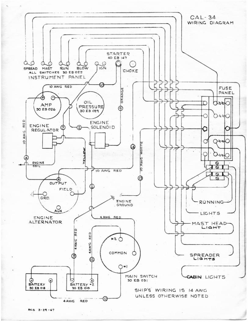
"' l l. S"",TCI<U ' 0 U IOZ S
INSTRuMENT PA NEL
E NC I Ni!: ALTERNATOR
o C.-OKE
/ " r"C I N~ GHtO\lNO
MA IN SWI TCf.,j :so U ! 0"
CAL - 34 W IRING DI A.C.RAM
F'U $E PANE L.
~ UC I-ITS
'-;>-;>- MAs,r HEA,_, '-'G, .... T
LIG I-I TS
SI-IIP'S WI RI NC 15 14 AWG
U N lE.SS OT!4ERWI~ e NO TE D
- - - '

•
1 1 1
2 4 2
CAL- }4
STANDING RIGGING
Headstay Backstay
- 9/32" 1x19 ,I. ,I. .j. X 39'10.1." Marine Eye &: Fork with x 42'O~~' ,' !·larine Eye &; 3/8" Tbd . x 4 '0", Nico Sleeve &: Snap Hook @
1" Pin , ShMk 8 ' 7"
- 7/ 32 ,. 1x19 Boom Lift OR OPTIONAL Adj . Backstay
Boom Lift Uppers Lowers Life Lines
l/B" 7x19
7/32" 1x19 s/s x 41 ' 8 5/8" . Marine Eye top &: 3/8" SIlel"llllln- Johnson Thd . Shank with han,H e bottom 1/8" 7x19 s/s 4'0", N1co Sleeve &: Snap Hook (j 8"4 "
1/)2" 1x19 s/s x 37'11;", Fork &. 3/8" Thd . Shank 3/16" 1x19 sis x 18'8; ", Fork &: 3/8" 'l'hd. Shank 3/16" 1x19 sis Plastic Coat x 29'6", Fork with Pel1can Hook &. .c-" Thd . Shank
NOTE :
1) All dimensions are center e~'e to eye or end of Thd. Shank.
2) On Insulated Backsta.ys, keep insulators as far apart as possible and the lower insulator above the Boom Lift Nico Sleeve.
1 1 1 2 1 2 1 1
1 2 1 1
1 1
Hain Halyard Main Halyard Jib Halyard :Ialyard Tal1s Main Sheet Jib Sheets Down Haul Out Haul
All lUre Standard.
" " " " " "
Spinnaker Halyard XS" Spinnake r Sheets 7 16" Topping Lift 5/16" Pore Guy 5/16"
x x x x
RUNNING RIGGING
1/8" 7x19 sis x 73 ' Wire Rope 1/8" 7x19 sis x )6'10" Wire Rope
3/16" 7x19 s/s x 39' 1" " ,. 3/8" x 40' Dacron Yacht Braid 3/8" x 84'" " "
7/16" x 45'" " " 5/16 " x 6'" " " 1/8" x 5'" " "
SPINNAKER GEAR
82 ' Daoron Yacht Braid 46' " " " 63 ' " " " 43' " " "
REEFING GEAR ON BOOM
Cl ew Pennant XS' x 30' Dacron Yacht Braid Tack Pennl1Ilt 5 16" x 17 ' " " "

CAL 34, BRIGHT TWO CABIN INTERIOR : The bright IwO cabin interior of Ihe Cal 34 is light and airy willi B windows and warm natural mabo!lany linis/l throu~. Forward cabin lias. doubl. berth. a S9atious hanging Iof:ker and a bIjt~n dresser. The head is pri'late!y separate!! Irom either cabin by .1wQ mahogany doors and contains 8 mirrored dreaing labl, Bnd I generous hanging locker.
CAL 34 - SPECIFICATIONS : SIAND.IJ!D EQUIPMENT HIII-O~ flftorCeo! 1""'",11 .~,go. fhd. mm; _ MId CPd!tt 1n!19''''.aIded libel"" ~ fIIIl1ld&1ionll dHt sWIll\lit Cob"II20 to chIow floool'''' __ sbI wrilOftg .. -""" .. II trltlO' 1flII • MlIIIIIIIIl 84nt CISIIud. J.15O ••. fiIgfII'I ~.ISI IOd bDooo. AI ....... ' ................ ,ICtI.,. fiIbog .... dt.!. IS u.Iru IItII 01 lIrOft/\l SwllCtll tenos and Em" .... pIoto •. II.., IIffJIII Dluan lflii ........ 1tI.Qt" ~ fIIIr,n ..... ,... '""' 23 """ -.lin R~~.- Mill ,.,. II 1IMiI ....... ""tt .... 1 ....... 1 ..rtf! liIocI:l. Sr_ .. ....t.eI ~,...1idI MIll ................. "',... nltt _ .... 4 _ .. dills ••
~ ~"{IIIm. "'ri...t"_~""_""'br ....... .. porU. If.,.,."", 2i g_~. $lJIOItu. SIMI '1M fIIIl. ~ 00Ia. WIth &1I0I0II ... "'-'-...... IAIan: F_ ...... Ibr •• W_I V·l!r>wt IIIIIIb 2 1 1IdI.ctu!I; 7 UIab 1lllmlflll1oP"d. WIllI ~I ttfIIrllb MIl _"_ flECHIlCAL eOUIP/.IEIIT 12 ~ barutr; ...... 01(1.,..111"111101. IIlMd iMIr,""" Pinel, 1ig~1IIf ill torwa-d comp_. beal, Q*y, ;,ntlll " Iddillga to .<1,,, .. ''''''"'1 1Igo/II1. 8frr!Jl, \.II ~rt'f1 c~ed IN .. ",thl. Ii""y Stlln!o1lltttll.ri to< fI'Iiu tOoU.,.., ..-I!lO III, icaba •. jour $10<"'1" dr .... "...,. tronh~g cupb(l.,d fJIMM. S .. t18 to 8 call1ko1Jb1y. trill _nl 0nI0, IIoutIII bt!Tl1 .
The Iar!19 galey is Ioc.ted on the st.rboard Side 01 tile main cabin wid! a lormiCi top" 5(1 lb. icebox, a stainless stnl sink with water pump 100 I room for • gimballed three oornSf stllYe. ' hert are two quarter berths for the ellra tal crewmen. and plant, 01 stowage SIlKa lor sails and other Rear.
LO.A. L W.l
••• D!I~
DIMENSIONS
3r:r HIllSI ,,-1(t" Silil AI"
_,,5·
JenKen marine
3.1511 1M 9,r,oo 1M
515 Sq Ft
.-~--.--135 FtSCHER STREET, COSTA MESA, CAlIF~92621
@/@/@/@/@/@/@/€l/€l /@/@/tm/<l3
•
..
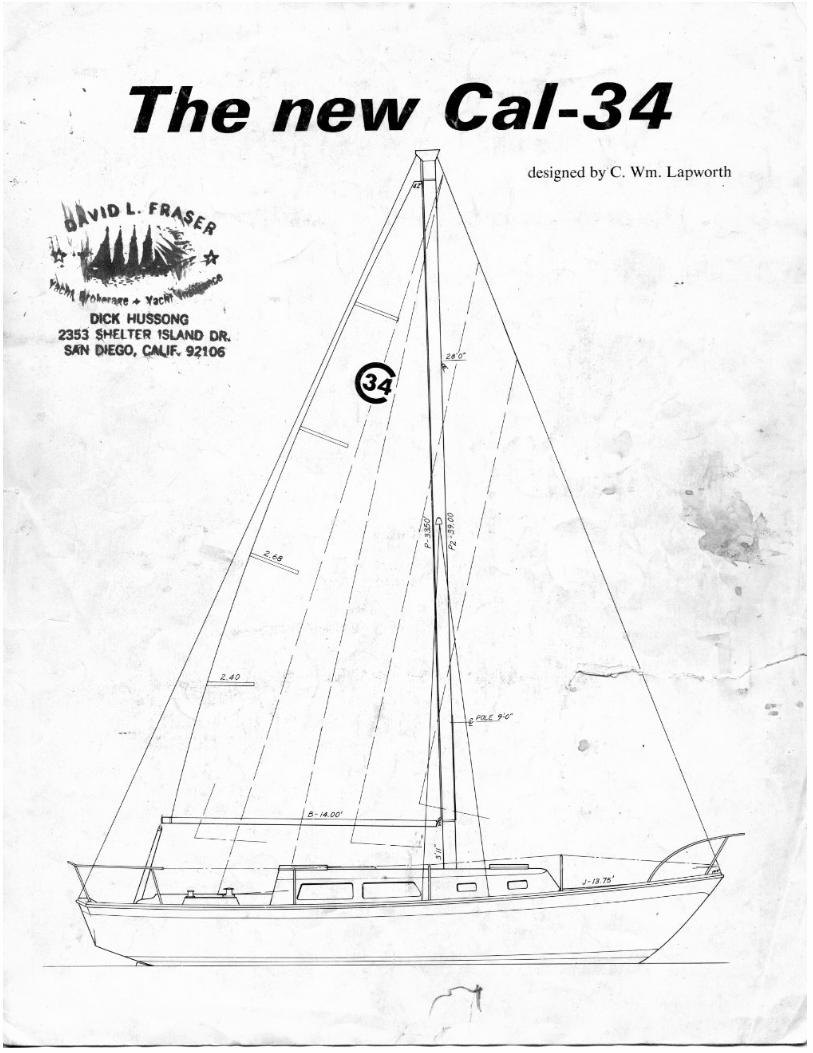
- :' The new Cal-34
~
~~~· .. v .......... ·"" DICK HUSSOHQ '
2353 $.HEl T£R ISLANO OIl SiN Dl£GO, CAUF~ 9?106
,.,
/
/ ! <g! , ! / I I
/ I k ,~ /! I'
/! I / I I
/ I I I / I I
/ I I I I ~ . ~ ()O/).
• ~ .
. -• _. -
designed by C. Wm . Lapworth
I j I
I I I ... •
I ! !
- -.~
""-"" II
'-= = J-/S ,,'
•
•
...----,
p •
•
• o ; \
• •
I I I, , .
• ',< I
, tm-; •
o \
,
~~----------------------