owner's manual - uni-seal pump - sealweld - valve · pdf fileowner's manual -...
TRANSCRIPT

Owner's Manual - Original Instructions
Doc. No. 100004
Rev. 0
Uni-Seal Pump
By Sealweld Corporation

This document is for the purpose of the Sealweld Uni-Seal operation only and is not considered a guide for
valve maintenance. We are pleased to offer a valve maintenance program “ValvePro®” and trust you will find
the lessons detailed in this program useful when maintaining the valves at your facility. Should you have any
questions regarding any of the ValvePro® procedures or if you know of any successful procedures you would
like to share, please contact us at:
Sealweld Corporation # 106, 4116-64 Ave. S.E., Calgary, Alberta, Canada T2C 2B3
Telephone: 1-403-236-0043 Fax: 1-403-236-5487 TOLL FREE 1-800-661-8465 Email: [email protected]
Web Site: www.sealweld.com
Sealweld (USA), Inc. 11430 Brittmoore Park Dr., Houston, Texas,, USA 77041
Telephone: 1-713-466-7373 Fax: 1-713-466-7778 TOLL FREE 1-800-624-4301 Email: [email protected]
Web Site: www.sealweld.com
ValvePro® Technical Support Telephone: 1-403-236-0043 Fax: 1-403-236-5487
Email: [email protected] Web Site: www.valvepro.com
The information in this handbook is intended as a guide only.
Always consult the valve manufacturers recommended maintenance procedures. No warranty is written or implied.
Use of product and/or company names is for reference only.
Sealweld®, ValvePro®, ACTIV-8®, SuperGun® and FLOW WOLF® are registered trademarks and/or patents of Sealweld Corporation.
Glossary of Valve Terms Copyright © Grove Valve & Regulator Company, 1980, 1993.
Reproduced compliments of Grove® Valve & Regulator Company
MADE IN CANADA
Revised 20/02/2014

Owner's Manual - Uni-Seal Pump Contents i
Contents
Introduction 3
Uni-Seal Pump Owner’s Manual ................................................................................... 3 SAFETY EXPLANATIONS .............................................................................. 3
Technical Data 4
Safety Considerations 5
Uni-Seal Pump Safety ................................................................................................... 5 Personal Safety ............................................................................................................. 6 High Pressure Hose ...................................................................................................... 6
Loading Instructions 7
How to Load a Uni-Seal Pump ...................................................................................... 7 To load from a cartridge ................................................................................... 7 To load with a stick-type grease ...................................................................... 8 To Load From a Grease Bag or Gun-Pack ...................................................... 9
Operating Instructions 11
How to Operate a Uni-Seal Pump............................................................................... 11 To Operate Pump .......................................................................................... 11 To Reload....................................................................................................... 13
Troubleshooting Hints 14
Minor Repairs to the Uni-Seal Pump .......................................................................... 14 To Extend Motor Life ...................................................................................... 14 Routine Maintenance ..................................................................................... 15 To Replace Leather And Nylon Cups ............................................................ 16 Cleaning the Motor Filter ................................................................................ 17
Parts List 19
How To Order Uni-Seal Pump Parts ........................................................................... 19
Warranty 21
Uni-Seal Pump Parts Warranty ................................................................................... 21 Disclaimer ................................................................................................................... 21 EC Declaration of Conformity ..................................................................................... 22 Contact Information ..................................................................................................... 23
Sealweld Corporation – Canada .................................................................... 23 Sealweld (USA), Inc. ...................................................................................... 23 ValvePro® Technical Support ........................................................................ 23

ii Contents Owner's Manual - Uni-Seal Pump
This page is intentionally blank.

Owner's Manual - Uni-Seal Pump Introduction Page 3
Introduction
Uni-Seal Pump Owner’s Manual
SAFETY EXPLANATIONS
Two safety symbols are used to identify where any action or lack of action can cause personal injury. It is very important that the user reads and understands the use of these symbols.
DANGER! – Danger is used only when an action or lack of action will cause serious human injury or death.
WARNING! – Warning is used when an action or lack of action can lead to a serious injury.
IMPORTANT! – Important is used when an action or lack of action can cause equipment failure, either over a long period of time or immediately.
The Uni-Seal sealant injection pump is one of the most effective tools for servicing large diameter pipeline ball, gate and plug valves. It offers a very simple field repairable design. The motor may be powered by compressed air, bottled breathing air or natural gas. The air/ hydraulic motor will generate up to 10,000 PSI injection pressure. The high speed action of the Uni-Seal pump makes it ideal for “popping” the plug out of its seat in tapered plug valves that become hard-to-turn.
WARNING! Read this manual completely BEFORE operating the pump.

Page 4 Technical Data Owner's Manual - Uni-Seal Pump
Technical Data
The Uni-Seal is a hand-held air/hydraulic injection pump. Pressurized air is connected to the air nipple (#10) on the OTC pump. Maximum inlet air pressure is 125 psi (8,6 bar) and the recommended air volume is 20 cfm (9,5 l/s). The maximum discharge pressure at the manufacturers settings are 10,000 psi (690 bar) and the delivery rate is approximately 16 ounces (0,5 l) per 2 minutes. The Uni-Seal pump weighs about 25 lbs (11 kg), when empty and is very portable. It can be loaded with 10 or 15 ounce cartridges and is designed to be easily reloaded with the use of an EZ-loader.

Owner's Manual - Uni-Seal Pump Safety Considerations Page 5
Safety Considerations
Uni-Seal Pump Safety
The Uni-Seal Pump is a power assisted sealant injection pump designed for injecting sealants, lubricants and valve cleaners into pressurized pipeline valves.
"Rusty" - All Dressed For Work
WARNING!
Always read and follow the valve manufacturer's recommendations before servicing any valve under pressure.
The Uni-Seal Pump is designed for use with compressed air from 60 PSI (4,1 bar) minimum to a maximum of 125 PSI (8,6 bar) and operates ideally at 120 PSI (8,3 bar). The air/ hydraulic motor draws approximately twenty cubic feet per minute (9,5 litres per second) when running at full capacity. You can get by with a relatively small air receiver/ tank because the time required to refill the sealant barrel will usually allow the compressor to refill the receiver/ tank
Always wear eye protection when operating the Uni-Seal Pump.
Be aware of the amount of energy this pump will generate and the mechanical limitations of the valve you are servicing.
Low-pressure, cast steel valves should not be lubricated with injection pressures in excess of 4,000 PSI.
Test the pump BEFORE attempting to service a valve. Repair or replace all worn, missing or broken parts of the pump before operating. DO NOT attempt repairs on the air/ hydraulic motor, other than to clean the internal filter assembly.

Page 6 Safety Considerations Owner's Manual - Uni-Seal Pump
Personal Safety
WARNING!
Stay alert. Do not use the Uni-Seal while tired or under the influence of alcohol, drugs or medications.
Dress properly. Always wear approved Personal Protective Equipment (PPE). Do not wear loose clothing or jewellery. Contain long hair. Keep your hair, clothing and gloves away from moving parts.
At all times, keep proper footing and balance, maintain a firm grip when using any sealant pump, and do not over-reach.
Maintain a safe working environment. Keep a clean work site. Ensure that you have proper lighting and that you have completed a Job Hazard Assessment (JHA). Ensure that you have the proper work permits and that your fellow workers are aware of the procedures and scope of work that you are about to perform.
ALWAYS turn off your vehicle and work well down wind of all sources of spark or ignition.
High Pressure Hose
WARNING!
Use only Sealweld Corporation replacement parts and hoses.
NEVER carry the Uni-Seal by the Hose Assembly #13.
Hose life is reduced by factors that include:
Environment - Temperature extremes, UV light, chemicals, ozone, etc. will degrade the rubber used in hydraulic hoses.
Abrasion and Cuts - Wear against other hoses or objects will wear off the outer cover and lead to corrosion of the reinforcing mesh.
Extreme Pressure Fluctuations - Pressure surges above the hose working pressure will damage hose components.
Improper Length/Routing - Excessive bending of the high pressure hose causes high stresses in the hoses components that may also reduce pressure capacity (avoid multi-plane bending, small bend radii, tension in hose, etc.). Hose life can be reduced by 90% when subject to these type of stresses.

Owner's Manual - Uni-Seal Pump Loading Instructions Page 7
Loading Instructions
How to Load a Uni-Seal Pump
Move the pedal to the OFF (RELEASE) position so that hydraulic fluid can return to the pump reservoir as sealant enters the sealant barrel. Make sure that dirt, sand or other contaminants do not get into the head or sealant barrel. These contaminants can plug sealant fittings and sealant passages inside the valve.
Remove # 4A head cap from barrel by turning counter-clockwise. Look inside the sealant barrel, you should see the piston assembly at the end of the barrel.
If sealant is found in the barrel, scoop the remaining sealant out by hand or re-attach the # 4A head cap and resume pumping operations.
To load from a cartridge
With an EZ-LOADER
1. Remove the cap from the cartridge of sealant. Unscrew the adapter from the end of the EZ-LOADER. Place the open end of the cartridge into the EZ-LOADER then push the cartridge inside the EZ-LOADER. The tail of the plunger will be pushed out the back of the EZ-LOADER as the cartridge slides inside. When the cartridge is fully inserted, remove the pull tab from the bottom of the cartridge before placing the adapter on the EZ-LOADER.
2. Screw the EZ-LOADER and adapter onto the end of the sealant barrel. Place the T-handle on the tail plunger on the floor or similar hard surface. Push the barrel down, this will force the tail plunger into the EZ-LOADER and transfer the contents into the sealant barrel.
IMPORTANT: Make sure that the foot petal on the motor remains in the OFF (RELEASE) position
while reloading.
3. When the T-handle is fully inserted into the EZ-LOADER, the sealant barrel is full. Unscrew the EZ-LOADER and adapter from the sealant barrel. Remember to remove the empty cartridge from the EZ-LOADER before storing the EZ-LOADER.
4. Place the head cap onto sealant barrel and tighten. If threads become gummed up with sealant, clean with penetrating fluid and clean rags.
5. With the head cap # 4A tightened onto sealant barrel, the pump is now ready for operation.

Page 8 Loading Instructions Owner's Manual - Uni-Seal Pump
Without an EZ-LOADER:
1. Remove the cap from the cartridge of sealant. Place the open end of the cartridge OVER the OUTSIDE of the sealant barrel. Make sure the foot pedal on the motor remains in the OFF (RELEASE) position during refilling procedures.
2. Set the pump assembly with the end cap down on the ground or similar location. Be careful not to constrict the hydraulic hose # 2 or the pump will not refill properly. Place your palm flat on the bottom of the cartridge and push the cartridge over the sealant barrel # 4C slowly. This will transfer the contents of the cartridge into the sealant barrel. As the barrel fills the piston assembly will be pushed to the bottom of the sealant barrel. When the end of the cartridge bottoms out the barrel is fill. Pull the quick tab off the end of the cartridge then slide the empty cartridge sleeve off the barrel.
3. Wipe the outside of the sealant barrel with a solvent rag or use penetrating fluid and a clean rag.
4. Place the head cap onto sealant barrel and tighten. If threads become gummed up with sealant, clean with penetrating fluid and clean rags.
5. With the head cap # 4A tightened onto sealant barrel, the pump is now ready for operation.
To load with a stick-type grease
1. Trip the foot petal on motor to the OFF (RELEASE) position. Push the piston assembly to the bottom of the sealant barrel with a wooden broomstick or similar object that will not scratch the inside of the sealant barrel.
2. Remove the plastic wrapper from the stick of sealant. Use a screwdriver to make several grooves along the length of the stick of sealant. This will allow air to escape from behind the sealant as the stick is inserted into the barrel. When stick is fully inserted, the pump is loaded.
3. With the head cap # 4A tightened onto sealant barrel, the pump is now ready for operation.

Owner's Manual - Uni-Seal Pump Loading Instructions Page 9
To Load From a Grease Bag or Gun-Pack
1. To avoid pumping the plastic bag into the sealant fitting or valve we recommend that the sealant be removed from the bag. Cut one end off the bag, place the open end of the bag into the sealant barrel.
2. With the bag fully inserted, squeeze the sealant out of the bag by holding the bag between your fingers and pulling the unopened end of the sealant bag. This will squeeze the sealant into the barrel.
3. With the head cap # 4A tightened onto sealant barrel, the pump is now ready for operation.


Owner's Manual - Uni-Seal Pump Operating Instructions Page 11
Operating Instructions
How to Operate a Uni-Seal Pump
The Uni-Seal Pump is a power operated sealant injection pump capable of injection pressures of up to 10,000 PSI. Its light weight and durable construction is well suited for portable work. The Uni-Seal pump has an extremely fast rate of delivery, (one pound (0,5 kg) in approximately two minutes). This quick injection capability makes the Uni-Seal Pump ideal for servicing large diameter valves or at plant facilities where large quantities of valves are found.
WARNING! Read all instructions BEFORE operating the Uni-Seal Pump.
Attach coupler # 6G to fitting on valve to be serviced.
Move the pedal to ON (PUMP) position. Pedal must be held down for the motor to run.
To stop the motor take your foot off the pedal.
To relieve pressure in the sealant barrel switch the pedal to the OFF (RELEASE) position.
Flow rate is approximately five seconds per ounce, this may vary depending on viscosity, temperature, inlet air pressure, and the length of the sealant hose. Any restrictions inside the valve such as plugged sealant channels can also hamper injection rates.
When finished servicing a valve always turn the motor OFF (RELEASE) to relieve sealant pressure before removing the coupler from the valve.
If the air/ hydraulic motor labors, this probably indicates the sealant barrel is empty. Check sealant gauge # 6C, it should indicate zero pressure. Switch the pedal to OFF (RELEASE) position.
IMPORTANT! When valve servicing is complete, and before storing pump:
1. Disconnect air supply at # 10 air nipple.
2. Switch pedal to the OFF (RELEASE) position to relieve hydraulic pressure.
3. Take out the breather cap and replace with shipping plug.
To Operate Pump
With the pump loaded and the barrel firmly attached to the head, the pump is now ready to operate. Make sure your air supply is attached to the air/ hydraulic motor (60 to 125 psi (4,1 to 8,6 bar) maximum). Slip the buttonhead coupler # 6G on the end of the sealant hose # 6E onto the buttonhead sealant injection fitting on the valve.
Step on the pedal of the air/ hydraulic motor which depresses the power button and forces the sealant out of the pump.

Page 12 Operating Instructions Owner's Manual - Uni-Seal Pump
Watch to ensure that a seal is achieved between coupler and fitting, and that sealant is not escaping. You can tell a seal is obtained by watching for leaks; keeping an eye on the gauge and listening to the air/ hydraulic motor begin to labor.
Routine Sealant Injection
Ideally a small amount of fresh sealant should be injected each time the valve is cycled, practically speaking valves see considerably less. Many operators have established preventative maintenance programs and add fresh sealant weekly, monthly, semi-annually, depending on service conditions. When the pump is attached to the sealant injection fitting, step on the pedal of the air/ hydraulic motor to force sealant into the valve.
IMPORTANT! Always read your pressure gauge and if any signs of trouble present themselves, repair
immediately.
Watch the gauge, once line-pressure is exceeded the pump should run steady at up to 2000 psi (138 bar) over line-pressure until barrel is empty. If the old sealant in the valve has hardened or otherwise deteriorated, higher injection pressures will be required. As the pump pressure climbs to 10,000 psi (690 bar) the pump will begin to labor.
High-Pressure Gauge Reading 10,000 PSI (690 bar)
To make sure fresh sealant is entering the valve take your foot off the foot controlled switch, but do not reverse pedal. You should watch the gauge reading slowly fall back to line-pressure.
To detach pump from valve fitting, reverse the foot controlled switch to OFF (RELEASE) position and the gauge will immediately fall to zero. Slip the coupler off the valve fitting and move to the next valve or fitting.
When Pump Is Empty
You can tell when the pump is empty when the air/ hydraulic motor begins to labor and the pressure gauge falls at the same time.
Owner's Manual - Uni-Seal Pump Operating Instructions Page 13
IMPORTANT! ALWAYS keep the pump in like-new condition and repair all worn or damaged parts
immediately in order to avoid personal injury.
To Reload
Reverse the foot controlled switch to OFF (RELEASE) position, check that the gauge registers zero pressure, detach head of pump and repeat loading procedure previously outlined. You should also periodically inspect and replace the Gasket in the top cap which seals against sealant barrel. The Gasket is not necessary except when pumping light lubricants or cleaners such as Sealweld® Valve Cleaner Plus.
CAUTION: The Uni-Seal Pump works on a 10,000 PSI hydraulic system.
WARNING! ALWAYS make sure all end caps and threaded connections are tightened firmly and repair
if there is ANY sign of leakage.

Page 14 Troubleshooting Hints Owner's Manual - Uni-Seal Pump
Troubleshooting Hints
Minor Repairs to the Uni-Seal Pump
The major moving part of the Uni-Seal sealant injection pump is the piston in the sealant barrel. We recommend replacing the nylon piston cups on an annual basis to prevent the possibility of sealant contaminating the hydraulic system. If this occurs we do not recommend that you attempt repairs on the air/ hydraulic motor. Motor repairs should only be attempted by trained service personnel. For motor repairs contact your local Sealweld® distributor or either Sealweld® office.
To Extend Motor Life
1. Tighten loose or leaking hydraulic fittings, replace hoses which have been damaged.
2. REPLACE ON AN ANNUAL BASIS (or as necessary):
nylon piston cup # 5C (1 each)
inner leather cup # 5G (1 each)
barrel gasket # 4B (1 each)
piston body O-ring # 5E (1 each)
barrel O-ring # 4D (1 each)
hydraulic fluid # 11 (2 each)
3. Run motor until sealant barrel is empty and motor begins to stall. Switch pedal to OFF (RELEASE) position, check gauges to MAKE SURE all pressure has been removed from system.
4. Remove head cap # 4A from barrel # 4C by unscrewing.
5. Place sealant barrel in a vise in an upright position (hose down, open barrel up).
6. Make sure motor is in OFF (RELEASE) position. Push piston assembly # 5 to the bottom of the sealant barrel # 4C with a wooden handle or similar object which will not score the barrel.
7. Switch pedal to the NEUTRAL position. Disconnect end cap # 4E from sealant barrel # 4C. Leave the end cap in an upright position to prevent leakage of hydraulic fluid.
8. Remove piston assembly # 5 from sealant barrel # 4C. Disassemble the piston by attaching piston wrench (Part No. R-A8-20G) to piston end nut # 5F and an allen wrench to piston set screw # 5A.
9. Should contamination be suspected, change the hydraulic fluid in the reservoir.
10. Inspect the old nylon and leather piston cups and O-ring for damage. Severe damage such as a nick or groove could be caused by scoring on the inside of the barrel. If sealant is present on the hydraulic side of the piston your hydraulic system could be contaminated.
11. Clean all parts and install new nylon and leather cups, leather goes toward the oil. Make sure cups are facing opposite directions. Replace piston body O-ring # 5E. Apply a small amount of Locktite No. 242 to piston set screw # 5A and piston end nut before tightening.

Owner's Manual - Uni-Seal Pump Troubleshooting Hints Page 15
12. Replace the end cap O-ring # 4D and hold upright.
13. Fill the motor reservoir with hydraulic fluid, then replace plug and run motor until hydraulic fluid appears in end cap (1/4" of fluid in the cap is sufficient).
14. Place the clean piston assembly in sealant barrel, always insert piston from the top end with the piston end nut # 5F down. The bottom of the barrel can be identified by the O-ring bevel cut in the end of the barrel. Move the piston assembly to the bottom of the barrel before attaching sealant barrel # 4C to end cap # 4E, make sure end cap O-ring # 4D does not get nicked or damaged while assembling.
Piston Break-In Procedure: After installing new piston cups # 5C and # 5G, it is recommended to run the piston up and down several times. This can be done by engaging the air/ hydraulic motor until the piston is seen at the top of the barrel, push the piston back down and repeat the procedure several times. Leave the piston at the top of the sealant barrel when complete. Be careful not to pump the piston out of the barrel.
17. Replace barrel gasket # 4B before tightening head cap # 4A and sealant barrel # 4C.
18. Tighten all threaded connections.
When completed, reload sealant barrel and test pump as detailed in "How to Operate a Uni-Seal Pump".
WARNING! DO NOT look directly down into the sealant barrel to watch piston! Place wooden handle
into sealant barrel and watch handle rise instead.
Routine Maintenance
Maintaining the pumps which are supplied with air from a rusted or dirty source such as compressors, tanks or lines should be equipped with an air filter and lubricator, this will add years to the life of the air/ hydraulic motor. Water should also be kept out of the pump. The hydraulic reservoir should be kept full, watch for signs of leakage through the breather cap or past the leather cup into the sealant barrel.
Consult the Uni-Seal Pump Owner’s Manual. Should the need for repair to the pump be realized either from being accidentally dropped or by the leather and nylon cup breaking down and the hydraulic fluid becoming contaminated with sealant or by simply wearing out.
Maintaining the Sealant Pump
Before operating, check all hoses for cracks or signs of leakage. Any damaged hoses should be replaced immediately. If any threaded connections show signs of leakage, tighten and check or replace. Keep the pump and hoses clean at all times, do not allow sealant build up anywhere. Make sure the gauge is not damaged in transit and reads accurately.
If the pump is used on a regular basis, your biggest concern is deterioration of the leather and nylon cup on the piston in the sealant barrel. These leather and nylon cups should be replaced semi-annually in order to avoid contamination of the hydraulic fluid.
Page 16 Troubleshooting Hints Owner's Manual - Uni-Seal Pump
To Replace Leather And Nylon Cups
1. Remove the end cap at the head of the pump and pump the piston to the end of the barrel, slowly. Pump until the nylon cup is extruding out of the barrel and grab it with your hand. Slowly pull out of the barrel, use the pump only if necessary.
2. Check to see that sealant hasn’t entered the hydraulic system. If traces of sealant are present, change the hydraulic fluid immediately.
3. Remove piston assembly # 5 from sealant barrel # 4C. Disassemble the piston by attaching piston wrench (Part No. R-A8-20G) to piston end nut # 5F and an allen wrench to piston set screw # 5A.
4. Inspect the old nylon and leather piston cups and O-ring for damage. Severe damage such as a nick or groove could be caused by scoring on the inside of the barrel. If sealant is present on the hydraulic side of the piston your hydraulic system could be contaminated.
5. Clean all parts and install new nylon # 5C, and inner leather # 5G cups, leather goes toward the oil. Make sure cups are facing opposite directions. Replace piston body O-ring # 5E. Apply a small amount of Locktite No. 242 to piston set screw # 5A and piston end nut before tightening.
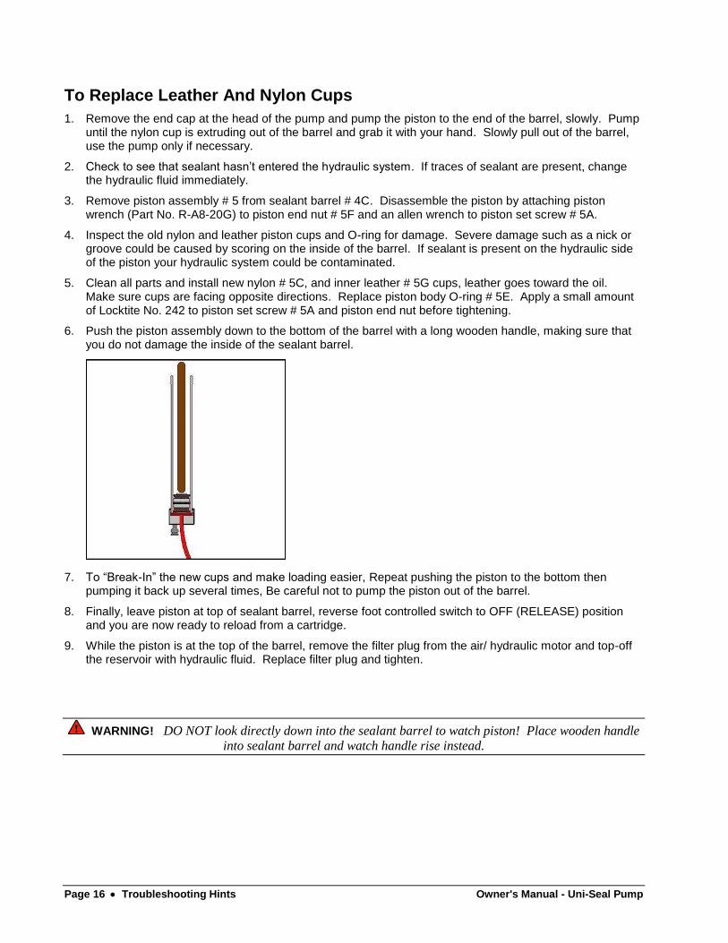
6. Push the piston assembly down to the bottom of the barrel with a long wooden handle, making sure that you do not damage the inside of the sealant barrel.
7. To “Break-In” the new cups and make loading easier, Repeat pushing the piston to the bottom then pumping it back up several times, Be careful not to pump the piston out of the barrel.
8. Finally, leave piston at top of sealant barrel, reverse foot controlled switch to OFF (RELEASE) position and you are now ready to reload from a cartridge.
9. While the piston is at the top of the barrel, remove the filter plug from the air/ hydraulic motor and top-off the reservoir with hydraulic fluid. Replace filter plug and tighten.
WARNING! DO NOT look directly down into the sealant barrel to watch piston! Place wooden handle
into sealant barrel and watch handle rise instead.
Owner's Manual - Uni-Seal Pump Troubleshooting Hints Page 17
Cleaning the Motor Filter
Occasionally sealant will by-pass # 5 piston assembly in the # 4C sealant barrel and enter the hydraulic fluid. The sealant may eventually clog the internal hydraulic oil filter in the motor. The motor may begin to operate unusually, generating only 2,000 or 3,000 psi (140-200 bar) before stalling. Should this occur, disconnect all air supply and relieve hydraulic pressure by placing the foot pedal in the OFF (RELEASE) position. Clean the top of the air/ hydraulic motor then remove the six set screws on the top of the motor. Lift the motor assembly out of the reservoir and turn over (let the oil drain back into the reservoir). On the bottom of the motor assembly you will find a filter assembly. Remove the filter assembly from the motor assembly and use air to blow it clean. Make sure that the ball and copper gasket are in good condition. Once cleaned, place the ball on the filter ball seat and the copper gasket on the filter, then fasten the filter assembly onto the motor assembly and then align the cork gasket and fasten the motor assembly back to the housing.
If motor does not begin to generate pressure within a few seconds after stepping on the pedal, there may be air in the hydraulic system. The air may be removed by tilting the foot pedal to the OFF (RELEASE) position and holding the power button under the foot pedal down by hand. Run the motor for approximately fifteen to twenty seconds. Trip the foot pedal to the pump position, pressure should build more quickly.
For motor repairs, contact Sealweld®. During the first year the pump must be returned to Sealweld® for Warranty Repairs. After the first year you may have the pump repaired by Sealweld® or one of our many distributors. Follow the suggested annual repair schedule and the motor should provide years of trouble-free operation.


Owner's Manual - Uni-Seal Pump Parts List Page 19
Parts List
How To Order Uni-Seal Pump Parts
Parts can be identified by referring to the illustration number. Ordering parts by the part number is the best way to ensure satisfaction.

Page 20 Parts List Owner's Manual - Uni-Seal Pump
Illustration # Description Order Part # Qty. Req'd
1 Air/ Hydraulic Motor - OTC Pump R-A8-16A2 1
2 6’ Hydraulic Hose H-HS-72HYD 1
2A Adapter - 1/4” M X 3/8” F H-AD-6F4M 1
3 Sealweld Sealant Fitting – ¼” Carbon Steel F-SW1/4-CS 1
4A Head Cap R-UG-1A. 1
4B Barrel Gasket R-A8-19A 1
4C Barrel R-A8-19B 1
4D Barrel O-Ring - Nitrile R-A8-19C 1
4E Bottom End Cap R-UG-04 1
4F Plug - 1/4" M NPT H-AD-4M 1
5 Piston Assembly R-A8-20 1
5A Piston Set Screw R-A8-20A 1
5B Piston Stop R-A8-20B 1
5C Nylon Piston Cup R-A8-20C 1
5D Piston Body R-A8-20D 1
5E Piston O-Ring R-A8-20E 1
5F Piston End Nut R-A8-20F 1
5G Inner Leather Cup R-HG-08H 1
6 Uni-Seal Pump Hose Assembly - Complete R-U-HOSE 1
6A Adapter - 1/4” M X 1/4” M H-AD-4M4M 1
6B High-Pressure Tee – ¼” H-T-444 1
6C 15,000 PSI Gauge with Rubber Guard H-GD-01C 1
6D Z Swivel - 1/4" x 1/2"-27 H-SV-Z1 1
6E Extra High-Pressure Hose – 60” H-HS-60XHP 1
6F Straight Swivel - 1/4” M X 1/2”-27 H-SV-ST1 1
6G Giant Buttonhead Coupler H-CPSG-2 1
10 Air Nipple R-A8-15A 1
11 Hydraulic Fluid R-HOPINT 2
Minor Repair Kit R-UG-MIN
Uni-Seal Repair Kit – 1 Year Spare Parts R-UGUN-1Y

Owner's Manual - Uni-Seal Pump Warranty Page 21
Warranty
Uni-Seal Pump Parts Warranty Sealweld® warrants its products only against defects in materials and workmanship.
Sealweld Corporation's liability and customer's exclusive remedy under this warranty extends for a period of one (1) year from the date of Sealweld Corporation's shipment and is expressly limited to repayment of purchase price, repair or replacement, at Sealweld Corporation's option, during said period, upon proof satisfactory to Sealweld® and upon customers returning and prepaying all charges on such products to factory or warehouse designated by Sealweld®. Warranty excludes normal wear items such as packings, seals and filters. Also excluded is equipment subject to corrosion, contamination, negligence, accident, or units, which have been altered in any way.
This Warranty is made expressly in lieu of all other warranties, express, implied or statutory, with respect to quality, merchantability, or fitness for a particular purpose.
Disclaimer The information contained within this manual is solely advisory.
You are responsible for understanding the information. You should not rely on this information as absolute. If you do act upon the suggestions contained in this manual, you are responsible for yourself and your actions.
Information contained herein is provided “as is” without warranty of any kind, either expressed or implied, including any warranty of merchantability or fitness for a particular purpose. The entire risk as to its quality, performance, or applicability is with you. If you rely on the information on these pages, you are responsible for ensuring by independent verification its accuracy or completeness.
Sealweld Corporation and its affiliates make no warranties, either expressed or implied, of merchantability or fitness for a particular purpose. This manual is published solely on an "as is" basis. Should the information in this manual prove to be false, misleading, or in contravention to law, statute, or regulation, you assume all risks. Sealweld Corporation and its affiliates will not be liable for direct, indirect (including, but not limited to any loss of business or anticipatory profits), incidental, or consequential damages resulting from your reliance on the information contained herein, even if the information was false, misleading, or in contravention to law, statute, or regulation, and even if Sealweld Corporation or any of its affiliates has been advised of the possibility of such.
No claims, promises or guarantees about the accuracy, completeness, or adequacy of the information contained in these
pages are made. In no event shall ANYONE be held liable for any loss of profit, special, incidental, consequential,
or other similar claims.
The illustrations, photos and images found in this manual are representations and are for illustration or 'for example' purposes only and do not necessarily represent the exact product or item being described. It is your responsibility prior to purchase to clarify the exact specifications of the product or item being purchased.
While every effort has been made to ensure its accuracy, this manual should be used as a general guide only and readers
are encouraged to adapt content to the circumstances within their particular workplace. No responsibility is taken by the
authors or publishers for any errors or omissions.

Page 22 Warranty Owner's Manual - Uni-Seal Pump
EC Declaration of Conformity
As defined by the provisions of the EC Machinery Directive 2006/42/EC, Annex II A
We declare that the type and design of:
Uni-Seal Pump
As supplied, are in conformity with the following relevant provisions:
Machinery Safety Directive 2006/42/EC
EN_ISO 12100-1 Basic concepts, general principles for design – Part 1
EN_ISO 12100-2 Basic concepts, general principles for design – Part 2
Manufacturer: Distributor Europe:
Sealweld Corporation - Canada Multimetaal Maintenance B.V.
_________________ ____________________
Signature Signature

Owner's Manual - Uni-Seal Pump Warranty Page 23
Contact Information Sealweld Corporation – Canada
# 106, 4116 – 64 Ave. S.E.
Calgary, Alberta
CANADA T2C 2B3
TOLL FREE 1-800-661-8465
PHONE 1-403-236-0043
FAX 1-403-236-5487
EMAIL [email protected]
URL http://www.sealweld.com
Sealweld (USA), Inc.
11430 Brittmoore Park Dr.
Houston, Texas
USA 77041
TOLL FREE 1-800-624-4301
PHONE 1-713-466-7373
FAX 1-713-466-7778
EMAIL [email protected]
URL http://www.sealweld.com
ValvePro® Technical Support TOLL FREE 1-800-661-8465
PHONE 1-403-236-0043
FAX 1-403-236-5487
EMAIL [email protected]
URL http://www.valvepro.com
Multimetaal Maintenance B.V. Scheepmakersweg 23 1786 PD DEN HELDER Postbus 703 1780 AS Den Helder THE NETHERLANDS
PHONE 1-403-236-0043 FAX 1-403-236-5487 EMAIL [email protected] URL http://www.valvepro.com