owner’s manual - drainvac.com · 4 5 sepa-03 : 120 volts sepa-04 : 230 volts titrehow the system...
TRANSCRIPT

OWNER’S MANUALPNEUMATIK SERIES
Cleaning Systems

TITRETITRE
INTRODUCTION
TABLE OF CONTENTS
We wish to thank you for your trust and congratulate you for having chosen a Drainvac product. It is a sound investment that will satisfy your vacuuming needs for years to come. The concept of Drainvac’s Pneumatik central vacuum cleaners is unique and patented. They are manufactured and checked at our plant by our qualified staff who have been specifically trained to this end. A number of installations and operating meth-ods must be followed to ensure your system’s maximum performance and to avoid unnecessary service calls. Please read this manual carefully.
REGISTRATION
HOW THE SYSTEM WORKS OPERATION SEQUENCE . . . . . . . . . . . . . . . . . . . . . . . . . . . . . . . . . . . . . . . . . . . . . . . . . . . . . . . . . . . . . . . . . . . 4
CONNECTIONS . . . . . . . . . . . . . . . . . . . . . . . . . . . . . . . . . . . . . . . . . . . . . . . . . . . . . . . . . . . . . . . . . . . . . . . . . . . 5
INSTALLING THE UNIT MINIMUM DIMENSIONS AND SPACING / FILTERED AIR HOSE . . . . . . . . . . . . . . . . . . . . . . . . . . . . . . . . . . . 6
INSTALLING THE PIPING SYSTEM GENERAL INFORMATION . . . . . . . . . . . . . . . . . . . . . . . . . . . . . . . . . . . . . . . . . . . . . . . . . . . . . . . . . . . . . . . . . . 7 DIFFERENT INSTALLATION POSSIBILITIES . . . . . . . . . . . . . . . . . . . . . . . . . . . . . . . . . . . . . . . . . . . . . . . . 8-9
EXAMPLES OF PROPER AND IMPROPER INSTALLATIONS . . . . . . . . . . . . . . . . . . . . . . . . . . . . . . . . . . 10-12
ELECTRICAL POWER SUPPLY PROCEDURE / EXAMPLES OF PROPER AND IMPROPER INSTALLATIONS . . . . . . . . . . . . . . . . . . . . . . . . 13
DIAGRAMS OF THE APPROPRIATE CONNECTIONS FOR YOUR MODEL . . . . . . . . . . . . . . . . . . . . . . . . . . . 14
MAINTENANCE PROCEDURES . . . . . . . . . . . . . . . . . . . . . . . . . . . . . . . . . . . . . . . . . . . . . . . . . 14
WEEE GUIDELINES . . . . . . . . . . . . . . . . . . . . . . . . . . . . . . . . . . . . . . . . . . . . . . . . . . . . . . . . . . . . . . . . 15
Cleaning Systems
To fill in the Drainvac product registration form, go to www.drainvac.com/client-support/register-your-drainvac
First off, we recommend you to fill out this form before you start the installation process. If you have any concerns or problems you may encounter, please contact the nearest retailer. The unit’s profile will be required.
*This information is found on a metal tag located on the left side of the unit.
Model* :Serial number* :Retailer name :Date of purchase :Date of the last maintenance :
Metal tag
IMPORTANT SAFETY INSTRUCTIONS• Use this separator only for its intended use as described in this manual.
• Do not allow the separator to be used as a toy. Close supervision is necessary when used by or near children.
• Do not pick up anything that is burning or smoking, such as cigarettes, matches, or hot ashes.
• Do not pick up any flammable liquids or combustible materials (gasoline, fuel, diesel) hot debris, waste solvents (paint or other), explosive materials that would cause harm to the vacuum cleaner.
• Avoid picking up hard or sharp objects to prevent damaging or block the hose and the plastic pipes.
• Do not put any object into openings. Do not use with any opening blocked. Keep free of dust, lint, hair and anything that may reduce airflow/suction. Lack of air flow will cause the motor to overheat.
• Never plug in a unit designed to operate with a current of 108V - 120V in a 220V - 230V outlet and vice versa.
• If the power cord is damaged, it must be replaced by a special cord available from the authorized local dealer/distributor.
• Do not use extension cords or outlets with inadequate current carry capacity.
• Never operate the separator if it has a damaged cord or plug, if it is not working properly. Return to authorized dealers/distributor for repairs.
• Never disconnect plug by pulling cord. To disconnect from the outlet, grasp the plug, not the cord.
• Never handle plug or cord with wet hands.
• Connect to a properly grounded (earthed) outlet only. See grounding (earthing) instructions.
• Keep cord away from heated surfaces.
• Turn off all controls before unplugging.
By overlooking safety rules, you might risk putting your health in danger and to those who surround you! Drainvac International disclaims any responsibility should you infringe upon these guidelines.
SAVE THESE INSTRUCTIONS

54
SEPA-03 : 120 VOLTSSEPA-04 : 230 VOLTS
TITRETITRE HOW THE SYSTEM WORKSHOW THE SYSTEM WORKS
Step 1Unit is off.
Step 2Start up : The dirt begins to be vacuumed
Step 3Automatic emptying in the wheeled bin.
Opening of the flap lid
Closing of the flap lid
OPERATION SEQUENCE
Wheeled bin
120/230 volts
To the vacuum
Air from the pipe system 120/230 volts
24-volt unit24 volts network
Filtered Air Hose100 Psi / 6.9 Bar
CONNECTIONS

76
IN 100PSI OUT
IN 100PSI OUT !
24” (60 cm)
9” (23 cm)
72” (183 cm)
TITRETITRE INSTALLING THE PIPING SYSTEMINSTALLATION
Filtered Air Hose100 Psi / 6.9 Bar
Fix the separator to the wall with the proper hardware.
Check the air inlet and outlet.
Cylinder
The following pages illustrate piping diagrams, typical installations and the parts that we recommend for the optimum performance of your central vacuum system.
• To determine where to locate the wall inlets, use the length of the vacuum hose as a basis, measuring the furthest point from the wall where the wall inlets are to be installed. Do the same for all the wall inlets until all areas of the house or building can be reached with the vacuum hose, by moving it from one wall inlet to another.
• If your walls are made of gypsum board, never install a wall inlet in the centre of the wall. Drill the holes for the wall inlets close to a wall stud or a door frame.
• Any screw length can be used if you install the piping as illustrated in Figure A.
• If you install the piping as illustrated in Figure B, make sure to position the small screw in the right place to avoid that a longer screw goes through the piping.
• Always use a short elbow when connecting the wall inlets (Figures A and B) to prevent long objects (for example, a pencil) that may have been vacuumed by mistake from blocking the piping further on.
GENERAL INFORMATION
Figure A Figure B
Small screw
Short elbow
FILTERED AIR HOSE
MINIMUM DIMENSIONS AND SPACING
It is important to install the unit in a location where it will be easily accessible for maintenance and to effectively evacuate the waste.
The following is the minimum spacing recommended:
Opened :58.5” (147 cm)
Closed :42” (106 cm)
98
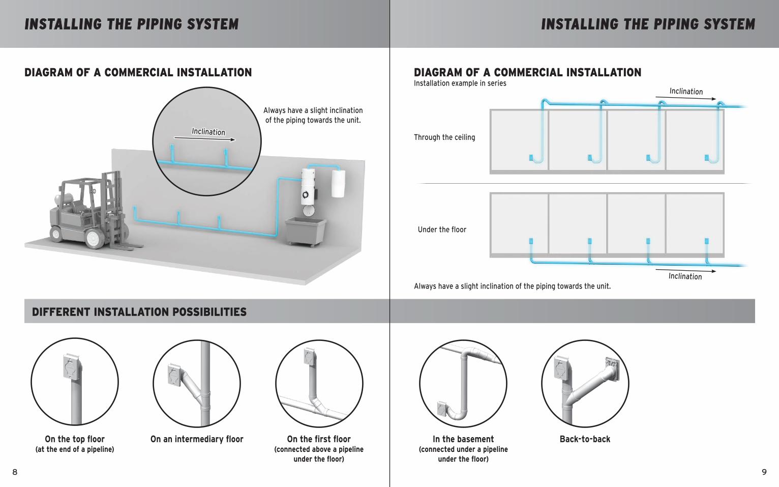
TITRETITREINSTALLING THE PIPING SYSTEM
DIAGRAM OF A COMMERCIAL INSTALLATION
On the top floor(at the end of a pipeline)
On the first floor (connected above a pipeline
under the floor)
On an intermediary floor
Always have a slight inclination of the piping towards the unit.
Inclination
INSTALLING THE PIPING SYSTEM
DIAGRAM OF A COMMERCIAL INSTALLATION
DIFFERENT INSTALLATION POSSIBILITIES
In the basement(connected under a pipeline
under the floor)
Back-to-back
Always have a slight inclination of the piping towards the unit.
Under the floor
Through the ceiling
Installation example in seriesInclination
Inclination

1110
TITRETITRE INSTALLING THE PIPING SYSTEM
EXAMPLES OF PROPER AND IMPROPER INSTALLATIONS
INSTALLING THE PIPING SYSTEM
EXAMPLES OF PROPER AND IMPROPER INSTALLATIONS
Joint with inside stoppers
Thick wallThin wall
For wall plates only
Smooth joint without inside stoppers

1312
TITRETITREINSTALLING THE PIPING SYSTEM
EXAMPLES OF PROPER AND IMPROPER INSTALLATIONS
ELECTRICAL POWER SUPPLY
• Install the 24-volt wires from the network (each wall inlet) to the separator and connect the 24-volt wires from the unit to the separator.
• Connect the unit and the separator to the electrical outlet with their power-supply cord.
• The separator and the unit are now ready to be used.
CONNECTION PROCEDURE
EXAMPLES OF PROPER AND IMPROPER INSTALLATIONS
24-volt wires

1514
1
2
Figure C
TITRETITRE WEEE GUIDELINESELECTRICAL POWER SUPPLY AND MAINTENANCE PROCEDURES
DIAGRAMS OF THE APPROPRIATE CONNECTIONS
SEPA-03: 15-amp. circuit / 120VSEPA-04: 16-amp. circuit / 230V
Electrical Panel
Besides, the only maintenance required is the cleaning of the filter cone inside the unit. To proceed, you just have to remove the porthole glass as illustrated, by pivoting it in an anti-clockwise motion using the handles.
This system is very user-friendly and we recommend a visual inspection through the porthole periodically or when needed.
MAINTENANCE PROCEDURES
This unit complies with the WEEE (Waste Electrical and Electronic Equipment) Guidelines, which promote the recycling of this type of waste equipment and encourage the development of products that are adapted to efficient waste reclamation at the end of their life cycle.
The WEEE Guidelines stipulate that the original supplier should agree to reclaim any obsolete equipment free of charge. We recommend that you advise your supplier that you would like him to reclaim your unit when you order and replace it with a new one.
Do not discard the unit with your regular garbage. The symbol representing a garbage bin on wheels on the unit’s label (Figure C) attests to this requirement. You must ensure that, at the end of its life cycle, your unit is reclaimed, treated and recycled by an authorized firm.
For more information, contact your municipal waste management department.
If you wish to speak with a customer service representative, please contact your supplier/dealer.
Drainvac International 2006 inc. — 150 Brunet Street, Mont-St-Hilaire, QC J3H 0M6, Canada
SUPPORT

LIV
R-1
4 -
PR
INTE
D IN
CA
NA
DA (0
1-19
)
Cleaning Systems