overview of training methodology for accident management ... · accident: (1) to prevent the...
TRANSCRIPT

IAEA-TECDOC-1440
Overview of training methodologyfor accident management
at nuclear power plants
April 2005
IAEA-TECDOC-1440
Overview of training methodologyfor accident management
at nuclar power plants
April 2005

The originating Section of this publication in the IAEA was:
Safety Assessment Section International Atomic Energy Agency
Wagramer Strasse 5 P.O. Box 100
A-1400 Vienna, Austria
OVERVIEW OF TRAINING METHODOLOGY FOR ACCIDENT MANAGEMENT AT NUCLEAR POWER PLANTS
IAEA, VIENNA, 2005 IAEA-TECDOC-1440 ISBN 92–0–101805–3
ISSN 1011–4289 © IAEA, 2005
Printed by the IAEA in Austria April 2005

FOREWORD
Many IAEA Member States operating nuclear power plants (NPPs) are at present developing accident management programmes (AMPs) for the prevention and mitigation of severe accidents. However, the level of implementation varies significantly between NPPs. The exchange of experience and best practices can considerably contribute to the quality and facilitate the implementation of AMPs at the plants.
There are various IAEA activities aimed at assisting countries in the area of accident management (AM). Several publications have been developed that provide guidance and support in establishing AM at NPPs. These publications include Safety of Nuclear Power Plants: Design, IAEA Safety Standards Series No. NS-R-1 (2000) and Implementation of Accident Management Programmes in Nuclear Power Plants, Safety Report Series No. 32 (2004). Separate technical reports are being prepared on methodology for severe accident analysis, the development and review of emergency operating procedures, and on training and technical support for AMPs. The safety service for review of accident management programmes (RAMPs) is offered to Member States; its purpose is to perform an objective assessment of the status at various phases of AMP implementation in light of international experience and practices. Various technical meetings and workshops are also organized to provide a forum for presentations and discussions and to share experience in the development and implementation of AMPs at individual NPPs.
The Safety Report on Implementation of Accident Management Programmes in Nuclear Power Plants plays a special role among the IAEA Safety Reports Series. It provides a description of the elements that should be addressed by the team responsible for preparation, development and implementation of a plant specific AMP at an NPP and is the basis for all other related IAEA publications. The Safety Report also underlines the importance of training for the successful implementation of an AMP. This present publication provides an overview of training methodology for AM. It discusses in greater detail the tools and support material that are applicable to the training of the staff involved in AM. Examples of such tools are also provided. This publication is mainly intended to facilitate the work to be performed by NPP operators, utilities and their technical support organizations in the area of the training required for AM.
The IAEA officer responsible for this publication is J. Mišák of the Division of Nuclear Installation Safety.

EDITORIAL NOTE
The use of particular designations of countries or territories does not imply any judgement by the publisher, the IAEA, as to the legal status of such countries or territories, of their authorities and institutions or of the delimitation of their boundaries.
The mention of names of specific companies or products (whether or not indicated as registered) does not imply any intention to infringe proprietary rights, nor should it be construed as an endorsement or recommendation on the part of the IAEA.
CONTENTS
1. INTRODUCTION.............................................................................................................. 1
1.1. Background ............................................................................................................ 1 1.2. Objective and scope ............................................................................................... 2 1.3. Structure of the document ...................................................................................... 3
2. ACCIDENT MANAGEMENT PROGRAMME AND TRAINING ................................. 5
2.1. Development of accident management programme............................................... 5 2.2. Role of training in AMP development and implementation .................................. 6 2.3. Review of accident management programme
and training seminar on accident management ....................................................... 7
3. OBJECTIVES AND ORIENTATION OF AM TRAINING............................................. 8
3.1. Personnel orientation.............................................................................................. 8 3.2. Content orientation................................................................................................. 9
3.2.1. Knowledge-oriented training...................................................................... 9 3.2.2. Skill-oriented training ................................................................................ 9 3.2.3. Efficiency-oriented training ....................................................................... 9
3.3. Function oriented training programme................................................................. 10
4. ACCIDENT MANAGEMENT TRAINING BY MEANS OF APPLYING THE PROCEDURES, GUIDELINES AND MANUALS........................... 14
4.1. Use of technical documentation for training ........................................................ 14 4.2. EOPs and SAM guidelines as training tools ........................................................ 14 4.3. Usage of SAM manual for training ...................................................................... 15 4.4. Use of guidelines and work charts for technical support and
other ERO aspects as training tools ...................................................................... 15
5. TECHNICAL SUPPORT TOOLS FOR AM TRAINING .............................................. 16
5.1. Operator aids ........................................................................................................ 16 5.2. Computerized tools .............................................................................................. 17 5.3. Use of simulators.................................................................................................. 18 5.4. Instrumentation availability.................................................................................. 19
6. CONCLUSIONS.............................................................................................................. 21
7. REFERENCES................................................................................................................. 22
ANNEX I SYLLABUS FOR TYPICAL IAEA SEMINAR ON ACCIDENT MANAGEMENT PROGRAMME DEVELOPMENT ...................................... 25
ANNEX II EXAMPLES OF TYPICAL COMPUTATIONAL AIDS.................................. 27
ANNEX III EXAMPLES OF ERO ORGANIZATIONAL CHARTS................................... 29
ANNEX IV EXAMPLES OF THE SEVERE ACCIDENT MANAGEMENT MANUALS........................................................................... 33
ANNEX V CHARTS FOR FOLLOWING INSTRUMENTATION AVAILABILITY AND SYSTEM DEPENDENCIES....................................... 35

ANNEX VI WORK CHARTS FOR AM ACTION PERFORMANCE................................. 36
ANNEX VII EXAMPLES OF COMPUTERIZED TOOLS................................................... 43
ANNEX VIII EXAMPLE OF TABLETOP SCENARIOS AND OBJECTIVES ................... 47
ABBREVIATIONS ................................................................................................................. 53
DEFINITIONS ................................................................................................................. 55
CONTRIBUTORS TO DRAFTING AND REVIEW ............................................................. 59
1. INTRODUCTION
1.1. BACKGROUND
The control and management of normal operation and upset conditions require well-defined operator instructions and a high level of performance of NPP personnel. An essential element of reaching and maintaining this high level of performance is personnel training. Training takes place on various levels and in various forms.
The concept of defence in depth is an essential element of nuclear safety. One of the levels of defence in depth requires that also beyond design basis accidents and severe accidents should be managed, although they were not explicitly addressed in the original design of the currently operating NPPs [1, 2]. The defence in depth is physically achieved by means of four successive barriers preventing the release of radioactive material (fuel matrix, cladding, primary coolant boundary, and containment). These barriers are protected by a set of design measures at three levels, including Prevention of Abnormal Operation and Failures (Level 1), Control of Abnormal Operation and Detection of Failures (Level 2) and Control of Accidents within the Design Basis (Level 3). If these first three levels fail to ensure structural integrity of the core, additional efforts are made at Level 4 of defence in depth in order to further reduce the risks. The objective at the fourth level is to ensure that both the likelihood of a severe accident (i.e. accident leading to significant fuel damage) and the magnitude of radioactive releases following a severe accident, are kept as low as reasonably achievable. The term AM refers to the overall range of capabilities of an NPP and its personnel both to prevent and mitigate the accident situations, which could lead to severe fuel damage in the reactor core. These capabilities include the optimized use of design margins, as well as complementary measures for the prevention of accident progression, its monitoring and mitigation of severe accidents. Finally, Level 5 includes off-site emergency response measures, with an objective to mitigate radiological consequences of significant releases of radioactive material.
The definition of AM as used in the IAEA Safety Report [3] states that “Accident management is the taking of a set of actions during the evolution of a beyond design basis accident: (1) to prevent the escalation of the event into a severe accident, (2) to mitigate the consequences of a severe accident, and (3) to achieve a long term safe stable state. Severe accident management (SAM) is a subset of AM measures with the objective to: (1) terminate the core damage once it has started, (2) maintain the capability of the containment as long as is possible, (3) minimize on-site and off-site releases, and (4) return the plant to a controlled safe state. AMP comprises plans and actions undertaken to ensure that the plant and its personnel with responsibilities for AM are adequately prepared to take effective on-site actions to prevent or to mitigate the consequences of a severe accident.” The IAEA definitions are in line with the definitions of SAM in OECD/NEA publications, for example in Refs [4, 5].
As specified above, AM comprises one of the key components of defence in depth. The AM provisions should take place regardless of all provisions within the design basis being adequate. The approaches to AM and SAM in particular vary in Member States. Some countries focus on actions to define procedures and SAM guidelines, which are based on utilizing the existing capabilities of the plant once a predetermined safety level has been achieved. In some countries, it is required that the plant modifications including hardware, instrumentation and control (I&C) and procedural changes be taken to improve significantly the plant capability of managing severe accidents without large releases to the environment.
1

Regardless of the approach, most countries have already implemented or plan to implement an AMP that includes development of the procedures or SAM guidelines or both. In addition, it is a part of the AMP to define the training programme for plant personnel who will be involved in SAM actions during an emergency. The main means for training are the classroom training, drills and exercises as well as the applicable simulator training, if available.
In most countries, SAM skills are not a formal request of the operator licensing. Consequently, the requirements for training are normally only set by the utility or the plant licensee. The first requirement is that the SAM training should not burden the control room operators excessively, since possibilities to increase the overall training time are limited. The SAM training cannot substitute the regular training programmes. The second requirement is that, nevertheless, the training should be efficient enough to ensure for the AM personnel sufficient skills to perform well during emergency situations when AM actions and their subset of SAM actions are needed. Therefore, it is particularly important to develop good training methods and to provide good and illustrative training material and support tools in order to ensure a high efficiency of training.
The IAEA Safety Report [3] also underlines the importance of training as a necessary condition for the successful implementation of an AMP. There is also an IAEA publication [6] that provides guidance for conducting the review of AMPs as an IAEA Safety Service. These two publications provide quite general statements on training related matters. The purpose of the current publication is to carry out a more detailed discussion of various items related to AM training. In particular, the aim is to describe different tools and support material that is available and their application to training. There is another special IAEA publication [7], devoted to the use of simulation techniques in AM training.
There have been several OECD/CSNI specialists’ meetings presenting the status of and discussing the available Operator Aids for Severe Accident Management, see Refs [8, 9, 10]. The material available from these meetings also provided valuable insights to the SAM training and to the supporting tools.
1.2. OBJECTIVE AND SCOPE
The main objective of this publication is to describe available material and technical support tools that can be used to support training of the personnel involved in the AM, and to highlight the current status of their application. The focus is on those operator aids that can help the plant personnel to take correct actions during an emergency to prevent and mitigate consequences of a severe accident.
The second objective is to describe the available material for the training courses of those people who are responsible of the AMP development and implementation of an individual plant. The third objective is to collect a compact set of information on various aspects of AM training into a single publication. In this context, the AM personnel includes both the plant staff responsible for taking the decision and actions concerning preventive and mitigative AM and the persons involved in the management of off-site releases.
Thus, the scope of this publication is on the training of personnel directly involved in the decisions and execution of the SAM actions during progression of an accident. The integration of training into the AMP development and implementation is summarized. The technical AM support tools and material are defined as operator aids involving severe accident
2
guidelines, various computational aids and computerized tools. The operator aids make also an essential part of the training tools. The simulators to be applied for the AM training have been developed or are under development by various organizations in order to support the training on different levels. The plant-specific AMP involves application plans and implementation of these tools.
The report concentrates on existing means, but an outlook on future prospects is also provided. Both preventive and mitigative AM measures, different training levels and different target personnel groups are taken into account.
The report pertains to light-water reactors and pressurized heavy-water reactors, but it can be used for power reactors of other types in the applicable parts.
The report is intended for use by those specialists who are responsible for planning, developing, executing and supervising the training of personnel involved in AM at NPPs.
1.3. STRUCTURE OF THE PUBLICATION
The available information on the training of personnel involved in AM is provided in this publication. In particular, the aim is to have a detailed overview of the training material and technical support for AM training. The report consists of six sections, and there are also eight annexes. The introduction provides background, objective and structure of the report. Section 2 summarizes development and implementation of an AMP of the NPP and describes in particular the training related items. The section deals with two separate areas of AM related training that are (1) training courses for developers, implementers and reviewers of the AMP and (2) training of the AM personnel having responsibility during the accident situations. Section 2 goes on and introduces the development of training material for the courses on the AMP. Such information may also serve as a useful starting point for the planning of the knowledge-oriented training after implementation of the AMP. The further sections make a clear distinction between these two areas. The objectives and orientation of AM training are the topics of Section 3. The training of staff to take correct actions includes various phases to improve knowledge, skills and efficiency of various AM personnel groups. Section 4 is devoted to procedural and documentary material that makes one of the essential building stones for the AM personnel training.
Finally, Section 5 summarizes the available AM support tools and prospects of further development. Description aims at specifying computational aids, computerized tools and AM simulator. The role of a SAM manual in training is discussed.
Concluding remarks are collected in Section 6 in order to summarize the status of the supporting means for AM training.
Annex I proposes contents for an AM training seminar that can be applied as an introductory course on severe accidents and AM for those who are responsible to develop the plant-specific AMP. Other Annexes list various computational aids that have been already applied in various plants (Annex II), organizational charts of emergency response organization (ERO) and work charts for emergency planning (Annex III). Annex IV gives an overview of SAM manuals developed by some utilities and compares their content and application. An example of a chart for checking instrumentation availability is introduced in Annex V and work charts for AM actions performance in Annex VI. Annex VII includes examples of the computerized tools developed to support execution of AM. Annex VIII provides examples of tabletop scenarios. The examples are presented in the format used in the source documents.
3
2. ACCIDENT MANAGEMENT PROGRAMME AND TRAINING
2.1. DEVELOPMENT OF ACCIDENT MANAGEMENT PROGRAMME
There are a wide variety of potential severe accident scenarios and sequence classes for each individual plant. The sequences start from different initiating events (precursors of a severe accident) that may lead directly or through additional failures to severe core degradation. The potential plant states include operation at power, the plant heat-up and cool-down, and shutdown conditions. Once started, the core degradation may further proceed to melting of the reactor core, to a melt-through of the pressure vessel and to a multitude of physical phenomena potentially challenging containment integrity. The further the accident progresses into the severe accident regime, the more difficult it becomes to manage the accident by the Emergency Operating Procedures (EOP). Therefore, many utilities tend to develop or have already developed Severe Accident Management Guidelines (SAMG) with a structure that is more appropriate for such situations.
In order to create the basis for managing core degradation situations, an understanding of plant-specific severe accident conditions should be created. Developing the AMP is the responsibility of the plant licensee that is the plant owner or the plant operator, or both. The IAEA has developed a Safety Report on Implementation of Accident Management Programmes in Nuclear Power Plants that provides guidance for the planning, development and implementation of the AMP [3]. There are various alternative ways to incorporate AM into plant operations. The selection of the best way in each individual case is influenced by the organizational structure and the available technical expertise of the utility as well as by the extent of the problem solving required to accomplish specific strategies. It is possible to incorporate preventive AM into existing procedures, to develop new procedures and guidelines for preventive AM and mitigative SAM, or to develop AM guidance manuals. The ‘procedures’ refer to a set of detailed reports, which prescribe specific actions in specified conditions, while the ‘guidelines’ and ‘guidance manual’ refer to a general description of actions that could be effective in managing a particular situation.
The personnel involved in the AM within the ERO are composed of different groups. Typically, as mentioned in Ref. [3], such groups are (1) control room operators, (2) a possible permanent or on-call safety engineer, (3) the part of the onsite technical support staff in charge of SAM guidance (often also called Accident Assessment Team, or Accident Management Team, AMT), (4) other parts of the technical support staff, such as an operating support staff, radiation protection staff, etc., and (5) off-site emergency operations staff of the plant licensee. The off-site organization includes one or more crisis teams where also the safety authority is involved.
Some examples of the on-site ERO are presented in Annex III 1. The implementation of the AMP should take into account that the availability of the technical expertise of the different groups may vary significantly among the utilities. The organizational aspects of the AM implementation include a definition of the roles and responsibilities of the personnel involved. The major functions for executing SAM guidance are the evaluators, decision makers and implementers, as described in Ref. [3]. The tasks of these different personnel groups may vary according to the phase of the AM. The implementation also varies among the
1 It should be noted that, in practice, many different organization forms exist, although many of the main functions are common to all approaches.
4
utilities, since the AM organization has to be integrated into the overall utility and plant organization and into the emergency organization.
When entering the domain of core damage, the progress and phenomena become more complex. It might not be so obvious what actions the operator has to take to terminate the accident progression or mitigate its consequences. In an actual case, the personnel responsible for the plant operation under emergency conditions have to make a number of critical decisions. These decisions include the confirmation that a severe accident has occurred, and they concern typically such issues as adding water to a degraded core, depressurization of the reactor cooling system and many containment related issues (e.g. using of sprays, flooding, filtered venting and hydrogen management, etc.).
The timing of these decisions depends on the individual plant design. Timing also may define the organizational level on which the decision should be taken. In the initial phase when the on-call safety engineers or technical support centre (TSC) are not yet available, the plant operators should be able to make the appropriate decisions. In the later phase when TSC staff are available, they can assist in or — where this is so organized — take over the decision making. The decisions are called critical in the sense that the implementation of the decision can also include adverse effects. In such a case, the guidance usually requires the TSC to consider these potentially negative consequences in advance as well as the consequences of not performing the actions. Balancing these positive and negative consequences, and the consequence of not performing the actions, can be a difficult task and, hence, should be trained for appropriately.
The personnel involved have to be trained in all aspects related to the decisions to be made. The training needs and methods have been specified in the Safety Report [3]. Many utilities have chosen to develop severe accident management guidelines, and, to develop in parallel, documentation that serves as background information for training and education. This background information is mostly derived from the technical basis that was used to develop the guidelines. Other utilities have adopted a practice to collect the guidance in a single SAM manual. This manual contains also all information that is deemed necessary for the operators and the technical support staff concerning severe accident progression and phenomena. The manual is an important part of the training material.
2.2. ROLE OF TRAINING IN AMP DEVELOPMENT AND IMPLEMENTATION
The Safety Report [3] addresses the training needs during the AM programme development and implementation phases. Accordingly, the important task of the development phase is to identify the training needs in time and to allow the preparation of the training programme to be carried out during the implementation phase. The training plan defines all staff members who need training as well as the level, scope and form of training for various groups.
During the implementation phase all personnel and groups that are required to provide a response during an accident should be clearly identified and their training needs well defined. Training of the personnel involved can be done both by classroom training and exercises and drills. Classroom courses can be used for the basic familiarization with the AM guidance. The drills and exercises, possibly applying simulators with severe accident modelling capabilities when available, provide efficient means for training. The emphasis is on the correct execution
5
of the EOPs in the phase before extensive core damage, the transition from the EOP domain to the SAM guidelines domain, and the proper execution of the SAM guidelines and other guidelines for the TSC. In addition to training the correct execution of the SAM guidance by the control room personnel and the TSC, the overall Emergency Preparedness Plan (EPP) should also be trained at regular intervals.
Drills should be performed in a way that all team members are trained at the similar level, i.e. too much emphasis on certain team members (e.g. the decision maker) should be avoided. The realism of the training may be improved significantly if the phase before extensive core damage and the transition from the EOPs to SAM is executed on a plant simulator.
An appropriate team that assesses the performance should observe the exercises and drills. The teams involved should also deliver a self-assessment and critique of their performance. Assessments are documented and filed, and the lessons learned are incorporated in the procedures, the guidelines and in the training itself.
In Ref. [3] the individuals and groups of the ERO that require training have been identified and the training levels defined. They include the control room staff and supervisors, the SAM guideline users and the emergency director. All of them need training of a different scope. There are also other interfacing personnel groups, the training of which is to be defined according to the plant-specific situation. Such personnel groups are those persons in the ERO and technical support staff who are not directly involved in the implementation of SAM guidelines as well as members of the off-site technical support centres.
In practice, there is considerable overlap between the different functions. The training needs of the different members of the organization can be evaluated separately. The level and contents of the classroom courses of severe accidents and the AM needs, means and practices in general could be different for these groups. As well the plant-specific training should be tailored according to the chosen approach to severe accident management and the function of the staff receiving it. Utility or vendor staff will normally provide plant-specific staff training.
The training should take place with regular intervals that are compatible with the overall operator and technical staff training programme of the plant. In any case, the training must take place at a frequency which will allow the responsible staff to be well informed and prepared.
2.3. REVIEW OF ACCIDENT MANAGEMENT PROGRAMME AND TRAINING SEMINAR ON ACCIDENT MANAGEMENT
The IAEA has prepared guidelines for conducting a review of the AMP as a standard Safety Service RAMP [6]. The preferable timing of the AMP review would be prior to the implementation and it can be done on different levels and phases. The publication [6] also provides some information on the related training aspects.
The plant licensee can start AMP development with a training seminar on accident management that would acquaint personnel who are to develop and implement the AMP with the various aspects related to severe accidents and to the AMP. The purpose of the seminar is to provide a background and description of AMPs to the team responsible for developing and implementing a programme at a particular plant. This will provide a sound basis for the subsequent project planning and implementation.
6

The seminar will provide an overview of AMPs, including understanding the objectives, scope and definition of AM, reviewing the different approaches available, and describing the tasks involved in developing and implementing a AM programme.
The seminar is intended primarily for the members of a team responsible for the selection, development and implementation of an AMP at a specific plant. It would be given before the AM programme development begins. Attendance would be expected from:
• NPP staff responsible for the development of the plant specific AM programme; • NPP management; • Regulatory body representatives responsible for review/overseeing development process;
and • Engineering support organizations including technical support companies, research
institutes and vendor organizations.
The seminar will be of a one-week duration, and will consist of lectures, discussion and exercise sessions. The seminar syllabus is shown in Annex I. It consists of seven modules:
• Introduction; • Plant behaviour during accidents; • Severe accident phenomenology; • Principles of AM; • Approaches and their features; • AMP development phases and tasks; • A workshop/exercise session to illustrate practically the use of AM guidelines.
The seminar will run for five days, each day consisting of six hours of lectures and/or exercises, plus one hour dedicated to a discussion of the concepts raised during the day. The exercises will use actual examples of accident management guidelines to illustrate their practical usage in a simulated tabletop scenario.
The training programme suggested for all AM personnel is addressed also in the RAMP guidelines [6]. Regarding the training, the items to be checked by the review team concern among others the timing for the training preparation in relation to AMP implementation, correct focus and training levels according to the personnel group, and in particular, use of the self-assessment and feedback from the lessons learnt during training.
The guidance publication itself, Ref. [6] can also be considered as sufficient material for the training of the reviewers.
7

3. OBJECTIVES AND ORIENTATION OF AM TRAINING
The main incentive for AM personnel training is to ensure that the ERO is capable of taking effective actions during accident conditions. For successful operation, it is necessary that AM personnel be acquainted with expected plant behaviour and consequences. The development and implementation of the AMP have resulted in procedures and guidelines that offer plenty of actions available for the staff. During the emergency it is important that the entire organization be capable of playing together in order to manage the situation. The training is given for various personnel groups according to their function during accident progression.
Three high-level objectives can be set to the AM training as discussed at the SAMOA-2 meeting, Ref. [8]. The first objective refers to educating the personnel in the knowledge of various severe accident phenomena that are instrumental for understanding the severe accident progression during various sequences. The second objective relates to training the AM personnel in skills to take actions during a severe accident situation. The third level is to improve the efficiency of the ERO by training the interplay and cooperation of all organizations involved. Accordingly, the three high-level objectives can be defined as:
• knowledge-oriented training; • skill-oriented training; and • efficiency-oriented training.
3.1. PERSONNEL ORIENTATION
As defined in connection to AMP development and implementation, there are various personnel groups involved: the control room operators, shift supervisors, on-call or permanent safety engineers, members of the TSC and the other relevant members of the on-site and off-site emergency organization. These groups have different AM training needs according to their function and responsibilities. In addition to the utility AM personnel, it is normal that the regulatory bodies have also technical staff to create their own group of experts during an emergency situation.
The classroom training periods are useful for all the groups involved, although the content of the classroom training may vary according to the group. In many cases, it is important to balance the AM training, particularly for the control room operators, whose annual training shall stay focused on performance-based responsibilities. Therefore, it is beneficial to find efficient and illustrative means for introducing the various aspects associated with severe accidents and AM. There are various simulation and demonstration tools that can be utilized to obtain a higher efficiency of the training that was discussed in a special publication of AM training simulation [7].
Training that improves the skills is needed for the personnel directly involved in the decisions and execution concerning the application of EOPs and SAMGs.
It is important that all the different AM personnel groups be involved in the drills and exercises since these offer the means to train and check the overall performance and efficiency of the AM as well as the interface to the other components of ERO.
Operations personnel training programme in AM domain shall cover knowledge-oriented topics on accident phenomenology to the extent necessary to support skill-oriented
8

training that is typically linked to the use of full-scope simulators. In the SAM domain it is important that operations personnel are trained in the transition from the EOPs to SAMGs, especially on the aspects of the transfer of responsibilities between the main control room (MCR) and TSC. Practical simulator exercises of this nature given to the all shift crews can be done in such a way that the instructors play a role in the TSC functions. It has to be recognized that large-scale exercises that involve the full TSC complex would not normally be available during training of the shift crews.
Training of the TSC personnel can also benefit from the use of the full-scope simulator as it adds realism in performance, especially in timing of events and effectiveness of the TSC decisions implemented on the simulator.
3.2. CONTENT ORIENTATION
3.2.1. Knowledge-oriented training
The first and basic part of improving the knowledge consists of classroom training. The lessons are aimed at teaching the personnel what would happen in cases of accidents progressing into core melt scenarios. The elements of theoretical lessons are a description of successive steps of core degradation and melting and an explanation of the most significant phenomena and their consequences on plant behaviour, and justification of recommended AM actions. An essential part is the definition and discussion of potential adverse effects as well as consequences of a partial or complete failure of AM actions on accident progression.
As complementary for the classroom training, it is useful to apply computer model based simulation aids or simulators for training in knowledge. The main features for such a simulator would be the consistency with models implemented in current training simulators for the phase from accident initiation to the onset of core melt and the use of state-of-the-art knowledge for modelling the severe accident phenomena. The plant changes and backfits would be implemented in modelling and the computer graphics would be most efficient to support classroom training and help personnel to understand accident progression. The modelling and simulation of system recovery as well as simulation of partial success of AM actions (e.g. possibility for interruption and showing the influence of full or partial success of water injection) would be needed to improve the correspondence to the actual situation. The simulator would need a fast running computational model, allowing discussion of specific issues in parallel with accident progression in the model.
3.2.2. Skill-oriented training
The main goal of skill-oriented AM training is to teach the personnel how to react in case an accident progresses into a core melt scenario. There are important items to be addressed specifically, such as the status of monitoring (instrumentation readings). The operator skills would be improved by exercising the execution of SAMGs and related measures. Consistent use of operator aids, if any, would be considered depending on utility objectives. It is crucial to analyse the operator response in such cases in order to properly understand respective human factor issues.
3.2.3. Efficiency-oriented training
The main goal of improving and testing the efficiency of the AM is to test behaviour of the whole organization. For a slowly progressing accident situation, many operators and technical support personnel would be involved in performing the job. The main tools to train
9

the efficiency are emergency drills and exercises. The issue to be analysed in the development phase is how to keep consistency of AM throughout the accident. The drills are an efficient tool for training the AM personnel e.g. to train the communication among the personnel involved in AM and to judge the plant status when shifts change, potential consequences for AM and potential divergence of the action, and finally, how to keep track of the whole scenario.
When implementing the plant-specific AMP, the training is done in parallel with the introduction of SAMGs.
3.3. FUNCTION ORIENTED TRAINING PROGRAMME
As described in Ref. [3], personnel assigned to work with SAMG are categorized into the positions decision maker, evaluator and implementer. This personnel has the following tasks and training needs:
1. Decision maker: The decision maker is designated to assess and select the strategies to be implemented.
He is in charge of making decisions in the use and implementation of SAM guidance. The function 'decision maker' can be placed in the accident management team or at a higher management level, up to the site emergency director. The decision maker should maintain a high-level perspective of all the SAMGs.
2. Evaluator: The evaluator is responsible for assessing plant symptoms in order to determine the
plant damage condition(s) of interest and potential strategies that may be utilized to mitigate an event. This function is assigned to members of the TSC accident management team tasked with the following activities:
• Diagnosing conditions that require entry into specific SAMG and transitions within SAM; • Evaluating the positive and negative impacts of actions directed in SAMG; • Responding to severe accident challenges; • Interpreting the response of plant parameters following SAMG strategy implementation; • Assessing the effectiveness of implemented strategies and determining whether additional
mitigation is needed; and • Using position-specific guidelines and work charts.
For example, TSC positions trained as evaluators are the operations liaison, reactor engineer, safety analysis engineer, and safety parameter display system (SPDS) operator.
3. Implementer: The implementer is responsible for performing those steps necessary to accomplish the
objectives of the strategies (e.g., hands-on control of valves, breakers, controllers, and special equipment). The normal ERO positions of the implementer are control room licensed operators.
Methodology for development of training The learning objectives and related training materials could be developed using a
systematic approach to training (SAT). This model consists of the following elements: analysis, design, development, implementation and evaluation.
10
The analysis phase of SAT consists of reviewing the various reports associated with SAM and determined those actions performed by the three basic job classifications: decision maker, evaluator, and implementer.
The design phase of SAT identifies the learning objectives of severe AM training for the three functions. The objectives are derived from an analysis of the various source reports pertaining to severe accident management principles and can be displayed in a matrix.
The development phase of SAT consists of the development of evaluation mechanisms (written exam questions, table-top scenarios, performance evaluations, etc.), utility specific training material (lesson plans, table-top scenario guides, etc.), and the application of the training prioritization criteria.
The implementation and evaluation phase of SAT includes the implementation of the training programmes and the evaluation of their effectiveness. These consist of conducting the actual training, obtaining ongoing feedback and evaluating the training programmes for future changes.
Evaluation of training The assessment of performance during drills should be based on the process used to
identify SAMG actions to be performed; thereby ensuring evaluations are made in a systematic method based on the best available information at the time.
Elements of a systematic evaluation of severe accident strategies should include the following:
• Diagnosis of plant conditions to determine the applicable strategies to be evaluated; • Verification of plant conditions and use of alternate indications; • Communication with the control room to determine available equipment; • Identification of positive and negative impacts of the strategy; • Identification of limitations and long term concerns; and • Follow-up to verify expected plant responses.
Post-drill debriefings will provide participants the opportunity to receive direct feedback from drill facilitators. Debriefings also allow the participants to provide direct input into the self-assessment process. During these debriefings, feedback forms should be made available to the participants giving them the opportunity to provide additional comments that may be factored into the assessment.
Input from drill controllers and the drill debriefings should be utilized to identify weaknesses and opportunities to improve performance. Comments that require further evaluation, training, or revisions to SAM documentation should be documented and tracked.
The level and intensity of the function-oriented training is presented in Table I.
11

TABLE I. EMPHASIS ON VARIOUS TYPES OF TRAINING FOR THE FUNCTIONAL STAFF GROUPS
Decision makers Evaluators Implementers
Knowledge-oriented training
** **** *
Skill-oriented training
* *** ***
Efficiency-oriented training
*** * *
The scale of emphasis is from '*' (meaning that only the basics needs to be trained) to '****' (meaning that the main emphasis should be here).
12
4. ACCIDENT MANAGEMENT TRAINING BY MEANS OF APPLYING THE PROCEDURES, GUIDELINES AND MANUALS
Such sources of background information as the technical basis reports and the SAM manuals provide valuable material for knowledge-oriented training.
The entire range of procedural and guidance reports of preventive and mitigative AM such as the EOPs, AM guidelines, SAM guidelines and SAM manuals have been written to advise the operator in controlling and managing severe accidents. These publications represent the most important material for AM personnel training in improving their skills and efficiency.
4.1. USE OF TECHNICAL PUBLICATIONS FOR TRAINING
Many technical publications are produced during the development phase of the AM programme. A part of this documentation can also be used as material for the classroom training phase of various personnel groups. An important departure point for the development of SAM guidelines is the technical basis publication.
As an example, the development of SAMG and SAMG training material in the USA is described. The work started by the collection of the relevant severe accident insights by EPRI in the so-called Technical Basis Report (TBR), Ref. [11]. In this report the major phenomenological issues were defined and examined with respect to the anticipated severe accident behaviour based on the knowledge of the individual phenomena at that time. This information was then used to assess the influence of possible high-level countermeasures that could be taken to recover from a severe accident, the so-called Candidate High Level Actions (CHLAs) on the various plant damage states. The Owners' Groups used the EPRI TBR plus other insights such as the plants individual plant examinations (IPEs) to develop generic SAM guidelines for the different plant types. As a final step, the utilities prepared the plant-specific procedures based on these publications. The Owners’ Groups developed from the TBR and the other insights the training documentation, which provided the necessary information for those responsible for executing the SAM guidelines. INPO also provided training material.
It is worthy to note that final implementation of SAM guidelines in the USA is licensee-specific depending on different plant design features, available technical support and operational practices of the utility. These features have also an impact on AM training. Nevertheless, the overall approach offers a possibility to use similar technical background material for training in the knowledge of severe accidents and execution of SAM guidelines.
4.2. EOPS AND SAM GUIDELINES AS TRAINING TOOLS
The procedural and guidance publications in themselves make an essential part of the AM training material.
When AM personnel are trained by means of exercises and drills, the teams of control room personnel and the TSC play a severe accident scenario. The emphasis is on the correct execution of the EOPs prior to core damage, the transition from the EOP domain to the SAM guidelines domain, and the proper execution of the SAM guidelines and guidelines for the
13

TSC (where these latter ones exist). Where a shift of responsibility occurs, e.g. from control room to the TSC on hitting an exit condition in the EOPs, this is to be trained explicitly.
In order to provide more frequent possibilities for AM personnel training, tabletop drills may turn out to be useful. The tabletop drills are efficient for training correct execution and transitions, but the full drills are still necessary for training of the aspects of the overall emergency plan.
The training should be done on the basis of an appropriate template that consists of a scenario plus all the branching needed to play the scenario in the actual drill. In developing this template, it is important to consider that a wide spectrum of SAM guidelines should be trained in parallel. The templates should also be flexible in the sense that not being able to predict different actions by the TSC and control room in sufficient detail, a range of possible responses should be considered. The template does not cover normally the whole core damage scenario due to its length in time, and therefore the jumps in the scenario are necessary in most cases. The templates are usually developed based on the integrated severe accident code calculations. When the plant simulators are available with the severe accident modelling capability, the use of such simulators can replace the pre-defined scenario with the pre-defined branching.
The templates, procedures and guidelines form the necessary framework for the exercises and drills. It is clear that AM personnel are supposed to follow this frame. Nevertheless, the success of the drill or exercise is assessed according to how well the teams have worked together, have followed their working procedures, and have established the proper level of communication, evaluation and decision making. Various examples of templates and objectives of using tabletop scenarios in training have been given in Annex VIII.
After the development of SAM guidelines, much attention is given to their validation before they are formally introduced. This validation is usually done at the final stage of the initial training. It is usually an extensive activity, which may take several weeks and involves all utility personnel assigned to the various TSC functions, often including the plant manager. It is executed in a large drill, where a broad spectrum of SAM guidelines is addressed. The validation is followed by a critique, where the lessons learned are drawn and fed back into the guidelines.
Later on, refresher training is organized at various intervals of two years or longer.
4.3. USAGE OF SAM MANUAL FOR TRAINING
The approach to writing a SAM manual as the support publication for the implementation of SAM actions has been adopted by some utilities. The contents and title of the SAM manual may vary, but essentially the publication contains various basic information on severe accidents and introduces the approach taken to manage severe accidents. Annex IV provides two examples of concrete applications in Sweden and in Finland.
Because of its information content on the physical phenomena, plant conditions etc. the SAM manual can be widely utilized for the knowledge-oriented training of all the personnel groups involved.
14

The main users of the SAM manual during the emergency depend on the actual organization and on the assignment of the responsibilities within the ERO. The applicability during an accident also depends on the structure and degree of detail of the manual. The users are normally within the TSC: at least some of the TSC personnel would be assigned to follow the SAM manual in more detail.
The feedback on the usability of the SAM manual for the skill-oriented training can be obtained from the drills and exercises. Accordingly, there is a need to upgrade the SAM manual at regular intervals.
4.4. USE OF GUIDELINES AND WORK CHARTS FOR TECHNICAL SUPPORT AND OTHER ERO ASPECTS AS TRAINING TOOLS
The execution of EOPs and — even more — of SAM guidance and other activities of the ERO can be a complex task for which a number of NPPs have developed specific guidelines and work charts. Typical functions to be executed by the TSC and described in the guidelines are:
• To evaluate the operability and reliability of instrumentation used to determine the values of EOP/SAMG control parameters (symptoms) and to develop a best estimate value for each parameter, taking into consideration any harsh environmental conditions that may damage I&C;
• To forecast the future values of EOP/SAMG control parameters, specify the current state of the plant with respect to certain conditions, and prepare alternate EOP/SAMG limit curves as appropriate;
• To evaluate the operability and reliability of plant systems, structures and components, both in short term and on a longer time interval, which may be used to perform functions specified in the EOPs/SAMGs; and
• To determine the priority with which systems should be restored to service, to optimize repairs by noting system interdependencies and to select restorative actions where chances are best taking note of the radiation levels at various locations, and to identify timing for actions directed by the EOPs/SAMGs.
Such guidelines should be used in classroom training as well as during a drill/exercise. An example of comprehensive guidelines is shown in Ref. [16]. An example of a chart to evaluate availability of the plant I&C and its environmental limitations is presented in Table V.1.
Apart from the guidelines for the TSC, all of the AM personnel shall be thoroughly familiar with applicable procedures and guidelines within their area of responsibility. Responsibilities and actions to be taken by individuals on strategic AM positions may be defined in different EPP documents. Therefore, AM position-specific quick reference summary work charts for performance of AM actions may be a very useful tool for training as well as for the execution of actions during a real event. An example of such a work chart in table form is presented in Annex VI. Such a work chart provides a summarized overview, i.e. applicable procedure or guideline identification, high level actions to be performed, and interfaces between personnel.
15

5. TECHNICAL SUPPORT TOOLS FOR AM TRAINING
Most technical support tools for AM training are the same as the tools for supporting AM personnel in the successful execution of SAM guidance during an accident. There are various operator aids that have been developed to support the AM personnel to follow and predict the accident progression, and thus to help in making decisions and taking corrective action. The operator aids have been developed in many countries and they range from the presentation and illustration equipment to the computational tools such as graphs and simple hand calculation tools up to more sophisticated computerized tools. In this section the operator aids are divided into presentation equipment, computational aids and computerized tools. The distinction between the latter two is made mainly on the level of sophistication. The fourth subsection then discusses the use of simulators with severe accident modelling capability for the SAM training.
As already mentioned, two specialists’ meetings have been organized by OECD to discuss and review such tools [8, 9]. The use of operator aids has also been summarized within Euratom research project SAMIME, Ref. [12].
5.1. OPERATOR AIDS
The NPPs are equipped with extensive control and monitoring capabilities that are available during a severe accident to a various degree depending on accident progression. The information available in an NPP was not originally designed up to severe accident conditions and its presentation is not necessarily optimal for use during such conditions. Therefore, various ways of presentation and illustration aids have been developed to support the control room operators and the TSC to follow the accident’s progression.
Many plants have already installed an operator support system that supports the use of symptom-based EOPs. Depending on application, the system can have different names such as the Safety Parameter Display System (SPDS), the critical function monitoring system (CFMS) or simply the operator support system. These display systems have capabilities to be helpful throughout a severe accident on the condition that the input from the plant instrumentation and computer system is available and reliable. When using this system during AM training, the availability and reliability in severe accident situation should be taken into consideration.
It is essential for the TSC to record accident progression. Wallboards and charts can be a very efficient means to record and monitor the plant damage states, trends of the parameters and the actions taken. Even a better solution can be to load such information into an internal computer network. In this case the information would be directly accessible by all the personnel involved in AM. There should be a person assigned to this task. The use of such arrangements and equipment should also be trained for properly.
In the case that dedicated equipment and instrumentation have been installed for SAM purposes, the control panels would be modified and there can be a separate control panel outside the main control room. The clear graphics and system mimics are good practice in these systems to help monitoring.
The instrument qualification tables and system dependency matrices as well as other process and instrumentation documentation will be needed during an accident. The
16

presentation of this information in an easily accessible form will be beneficial. The next chapter discusses the use of computer presentation for such information.
In order to ensure the good performance of AM personnel during an accident situation, many tools have been developed recently in the form of pre-calculations or based on using separate computer capacity. These tools are called computational aids and they should be accounted for in the development of the AMP for the plant. They can provide estimates of parameters which affect AM decisions, such as reactor coolant system (RCS) integrity and containment leak rates, remaining time to key events (e.g. to core uncovery, reactor vessel failure and containment failure) and core and containment conditions. They should also provide a basis for assessing the effectiveness of strategies under consideration or in progress during an accident.
The computational aids can be in the form of a parameter graphs, diagrams, a set of formulae, a compilation or a table of plant-specific information, or small computer programmes. The aids are typically plant-specific and they are developed in line with development of the AMP. For example, a U.S. utility operating various plant designs has developed a set of calculational tools in the form of the computer programmes that provide critical engineering information calculations on timing of critical milestones, critical plant data and plant response to severe accidents, Ref. [13]. A list of computational aids and two examples of computational aids are presented in Annex II.
5.2. COMPUTERIZED TOOLS
Significant progress has been made in the development of on-line diagnostics and simulation capabilities that could enable TSCs or other accident response centres (e.g., national emergency response centres), and in particular off-site emergency management teams to supplement their technical basis for decision-making. Such tools are referred to as computerized tools.
The functions of the computerized tools include accident tracking, on-line symptom-based diagnostics, and fast-running accident simulation capabilities to enable better assessment of trends, and determination of the potential implications of severe AM alternatives, well before such actions may become necessary. In addition, as these computerized tools and advanced simulation methods become more developed, they can be used in extending and supporting the execution of SAM guidelines in areas such as parameter trends, equipment availability, and trade-off analysis of alternative SAM actions.
The predictive simulator is, in principle, interactive; i.e. severe AM actions can be tested to study their effect in advance. The input for the predictive calculations is taken from the actual plant data. The speed of calculations can be much higher than the real time. The predictions are used e.g. for determining the timing of deliberate release (venting).
Annex VII provides a short description of some computerized tools and advanced simulation systems. It is noted that the current users of the computerized tools are nuclear regulatory authorities and to a lesser extent, the TSCs and other utility organizations.
Determining the availability of systems and equipment that could be used for executing the SAM actions takes time during an emergency. In some cases the SAM guidelines include a series of tables, which summarize the data pertinent to the use of pre-identified equipment and systems. The system dependencies are important for some actions, but it may be laborious to work them out from the documentation available. The experience shows that in practice the
17
AM personnel often consult the paper copies of the plant process and instrumentation (P&I) drawings and equipment and system manuals. Further development of computerized database for the instrumentation availability, system dependencies and other important P&I information could assist AM personnel in making these determinations.
Parameter trends are very important for AM personnel for many reasons. First, it can be the primary tool for predicting such important timings as time to steam generator dry-out, to containment challenges and to hydrogen burn. Second, it can be the method for monitoring the plant behaviour after strategy implementation. Third, it permits the taking of actions prior to reaching actual setpoints. Use of computerized tools, particularly in the case of access to the process computer, can assure that trending is based on relevant data and that relevant parameters are trended.
There are also other cases, where further development of computational aids would be useful. The status of equipment repair and predicted time of availability is not easily tracked by AM personnel during an accident. Recovery of unavailable equipment is one of the prime SAMG strategies. During the accident progression the priority for the equipment repair may change. Again, a computerized database that can maintain the current repair status would be useful for the AM personnel.
The computer-based system to predict the onsite radiation levels is very useful to give information for the AM personnel on the accessibility of the equipment. Such a tool can be developed based on the projected fission product releases from the primary circuit and from the containment. The same system can be further applied as the interface between the AM personnel and the team responsible for the off-site dose predictions. Such a system has been developed for the Loviisa SAM usage and is currently under testing phase [14].
The computerized tools could also play an important role in extending and supporting the execution of the SAM guidelines for such items as parameter trends, equipment availability, and recording of timing.
The main users of the computerized tools in accident progression are foreseen to be the emergency teams. For the final application during the emergency, the training is connected to the emergency drills. Current trends indicate that the TSC with sufficient expertise could also benefit from the use of computerized tools.
5.3. USE OF SIMULATORS
There is a specific IAEA publication on the application of the simulation methods for the AM personnel training [7]. In the present section, the outcome of that report is highlighted. It has been recognized in Ref. [7] that the simulators and simulation in general provide an efficient tool for AM training.
The current state of severe accident modelling has made it possible to develop many different approaches to the simulation that can be used to support the AM training in the utilities. The various techniques include introduction of graphical interfaces into existing severe accident codes, installing a severe accident code to an existing simulation environment, and developing specific models tailored for the SAM purposes of the given plant. The current state of the art in the computer technology is sufficient for simulation of severe accidents on full-scope replica simulators. Such simulators may be very valuable tools to support preparation and performance of larger-scale emergency exercises and drills but should be cautiously used for training of operators. As the uncertainties in severe accident simulation are
18

unavoidable, training scenarios shall sufficiently vary to eliminate the development of such an impression that the plant behaviour during severe accident conditions would necessarily follow a specific pattern.
Simulators contribute to the training of the people, having this large variety of tasks and responsibilities. Hence, for AM the emphasis is not primarily only on the full-scope replica, but on any simulator that can provide useful functions. An example is the development of appropriate templates, as a major drawback in drills usually is the need to pre-calculate various scenarios and to anticipate operator interaction, together with cuts and interruptions in the scenario. The use of an interactive simulator would largely overcome these problems.
The severe accident simulating methods have turned out to be an effective tool for classroom training to explain and display the phenomena and progression of severe accidents. In these cases, the simulation method can be a sophisticated severe accident analysis code that has been equipped with illustrative graphical interface.
An important aspect for simulators would be the training of the communication of SAM between the MCR and the TSC. In general, SAM domain simulators are useful as long as meaningful countermeasures are possible to be simulated. Where these cease to exist, pre-calculated scenarios presented on paper would largely be sufficient.
The simulator is an effective tool to detect and improve weak elements of human behaviour in SAM, as it provides the appropriate physical environment. The more realistic the simulator is, the better these elements are taken into account.
The use of simulation in the SAM space is limited due to uncertainties and limits in the scope of simulation, but such incompleteness is acceptable as long as it is well understood by the trainees, what is the range of the impacts on the outcome. The incompleteness should be covered by some other means of training.
The simulator can be used to verify SAM guidelines if the models used are sufficiently accurate, and to validate these if the simulator is sufficiently close to the control room lay-out. At present, simulators hardly include low power and shutdown states, although the risk from these operational states is considerable. This area should be further developed.
Finally, some developments exist in expanding full-scope simulators into the severe accident regime. This development should be followed and the lessons learnt should be fed back into simulator application.
5.4. INSTRUMENTATION AVAILABILITY
The availability of measurement information for AM personnel is of crucial importance during an emergency situation to guide the decisions and actions and to monitor the accident progression and efficiency of performed measures. Different approaches exist to ensure the needed information. Some utilities and plants have chosen the approach to install and qualify dedicated instrumentation for those measurements that are needed for performing the proper preventive and mitigative SAM actions and monitor their success. Such an approach has been presented for the Finnish NPPs in Ref. [15]. Another approach that is widely adopted is to take efforts to estimate the reliability of information obtained from the existing measurements and instrumentation and to use information from different sources to support the decisions during the SAMG execution.
19

Not depending on the chosen approach, the training should address the issue of instrumentation availability and reliability. The operator has to know on what he can rely during the situation when he is supposed to take SAM actions.
In case the dedicated instrumentation has been installed for the critical SAM functions, the situation can be governed easily by emphasizing the use of the dedicated information.
Checking the validity of the instrumentation readings is an important task when the used measurements are not qualified to severe accident conditions. Many efforts have been taken in various countries to study the instrumentation availability and reliability. The results are often very plant specific and the resulting documentation is extensive. The obtained material has to be processed for the use of AM personnel. The usefulness of the plant-specific information can be improved by applying modern computer-based processing. The readings should be checked both from the perspective of the expected response during a severe accident and a comparison to other instrumentation. Computerized tools would be useful to alert the user when the accident has progressed to a point where certain instruments may not longer be valid and when the instrument readings deviate from those of the corresponding measurements.
20

6. CONCLUSIONS
Many utilities have already implemented or plan to implement AMPs in their NPPs, which include development of the SAM guidelines as an essential element. Along with it is a part of the AMP to define the training programme for plant personnel who will be involved in SAM actions during an emergency. In most countries, SAM skills are not a formal regulatory requirement for operator licensing. Consequently, requirements for training are normally only set by the utility. The training programme should be efficient to provide sufficient training without bringing an unnecessary burden on the operators' training programme. Consequently, efficient training methods are essential. Illustrative training material and support tools can be very helpful in achieving these objectives in order to ensure high efficiency of training.
The high-level objectives of the AM training are improving the knowledge of the all responsible staff on the all aspects of severe accidents and their management, improving the skills of the plant personnel involved in the AM and improving the efficiency of the ERO. The training contents, methods and tools depend on the objective and also on the target group to be trained. The classroom training can improve the knowledge, the tabletop and simulator exercises can improve the SAM skills and the drills and exercise can improve the overall response of the ERO.
The EOPs for the preventive AM and the SAM guidelines for the mitigative SAM are the essential part of the training material when improving the skills and efficiency. The background material such as the technical basis reports and the SAM manuals provide valuable material for the knowledge-oriented training.
The operator aids that have been developed for supporting personnel are used as technical support tools for AM training. The operator aids range from presentation and display means to computational aids such as graphs and simple hand calculation tools up to more sophisticated computerized tools.
The computational aids are plant-specific and are developed in line with development of the AMP. Parameter trending is crucial for AM personnel since it can be the primary predictive tool for important timings and it permits the taking of actions prior to reaching an actual set-point. Significant progress has been made in the development of on-line diagnostics and simulation capabilities that could enable the TSC and other accident response centres (e.g. national emergency response centres, etc.) and in particular off-site emergency management teams to supplement their technical bases for decision-making.
The current state of severe accident modelling has made it possible to develop many different approaches to the simulation that can be used to support the AM training. The techniques include introduction of graphical interfaces into existing severe accident codes, installing a severe accident code to an existing simulation environment, developing specific models tailored for the SAM purposes of the given plant and equipping a full-scope simulator with severe accident models. An important aspect for simulators would be the training of the communication between the main control room and the TSC. The simulator is also an effective tool to detect and improve weak elements of human behaviour in SAM, as it provides the appropriate physical environment. The severe accident simulators have limitations due to uncertainties and insufficient modelling. However, for simulators to become effective training tools, they should enable the simulation of the expected range of uncertainties.
21


REFERENCES
[1] INTERNATIONAL NUCLEAR SAFETY ADVISORY GROUP, Defence in Depth in Nuclear Safety, INSAG-10, IAEA, Vienna (1996).
[2] INTERNATIONAL ATOMIC ENERGY AGENCY, Safety of Nuclear Power Plants: Design Requirements, IAEA, Safety Standards Series No. NS-R-1, IAEA, Vienna (2000).
[3] INTERNATIONAL ATOMIC ENERGY AGENCY, Implementation of Accident Management Programmes in Nuclear Power Plants, Safety Report Series No. 32, IAEA, Vienna (2004).
[4] OECD NUCLEAR ENERGY AGENCY, Implementing Severe Accident Management in Nuclear Power Plants, OECD, Paris (1996).
[5] OECD NUCLEAR ENERGY AGENCY, Severe Accident Management: Prevention and Mitigation, Report by a NEA Group of Experts, 1992.
[6] INTERNATIONAL ATOMIC ENERGY AGENCY, Guidelines for the Review of Accident Management Programmes in Nuclear Power Plants, Services Series No 9, IAEA, Vienna (2003).
[7] INTERNATIONAL ATOMIC ENERGY AGENCY, Application of Simulation Techniques in Accident Management Training in Nuclear Power Plants, IAEA-TECDOC-1352, IAEA, Vienna, (2003).
[8] OECD NUCLEAR ENERGY AGENCY, Specialist Meeting on Operator Aids for Severe Accident Management and Training (SAMOA), June 8–10, 1993, Halden, Norway, NEA/CSNI/R(93)9.
[9] OECD/NEA, Second Specialist Meeting on Operator Aids for Severe Accident Management and Training (SAMOA-2), 8–10 September 1997, Lyon, France, NEA/CSNI/R(97)10.
[10] OECD NUCLEAR ENERGY AGENCY, Severe Accident Management (SAM) Workshop on Operator Training and Instrumentation Capabilities, OECD/CSNI, 12–14 March 2001, Lyon, France, NEA/CSNI/R (2002) 11.
[11] B. CHEXAL, A. SINGH, J. CHAO, R. HENRY, Update on the Technical Basis for the Severe Accident Management Guidelines, OECD Specialist Meeting on Severe Accident Management Implementation, Niantic, Connecticut, June 12–14, 1995.
[12] Concerted Action on Severe Accident Management Implementation and Expertise in the European Union, Contract F145-CT98-0652, AMM-SAMIME-P009, December 2000.
[13] M. BONACA, A. GHARAKHANIAN, “Calculational Tools Supporting Northeast Utilities Emergency Organization”, OECD/NEA, Specialist Meeting on Operator Aids for Severe Accident Management and Training (SAMOA), NEA/CSNI/R(93)9, Halden, Norway, June 8–10, 1993.
[14] T. ROUTAMO et al., Data Information System for Radiation Experts, Paper presented at the OECD Severe Accident Management (SAM) Workshop on Operator Training and Instrumentation Capabilities, 12–14 March 2001, Lyon, France, NEA, CSNI, 2002.
[15] H. TUOMISTO, A. FELIN, A. LUCANDER, J. TUURI, S. KOSKI, "Severe Accident Management Instrumentation in the Finnish NPPs", Proceedings of the 1. OECD/CSNI Specialist Meeting on Instrumentation to Manage Severe Accidents, GRS-93, NEA/CSNI/R(92)11, pp. 291–302, Cologne, Germany, March 16–17, 1992.
[16] Technical Support Guidelines for the BWROG, ERIN Eng., 1998.
23


DEFINITIONS
The definitions that follow are provided solely for the purposes of this publication.
accident management accident management programme beyond design basis accident (BDBA) computational aid computerized tool core damage core degradation design basis accident (DBA)
The taking of a set of actions during the evolution of an event sequence to a beyond design basis accident: to prevent the escalation of the event into
a severe accident; to mitigate the consequences of a severe
accident; — and to achieve a long term safe stable
state. Comprises plans and actions undertaken to ensure that the plant and its personnel with responsibilities for accident management are adequately prepared to take effective on-site actions to prevent or to mitigate the consequences of a severe accident. Accident conditions more severe than a design basis. Pre-calculated analyses, nomographs or user friendly computer software available for plant staff use during a severe accident: 1) to support plant staff guidance, 2) to predict accident phenomena and timing, and 3) to evaluate the effectiveness of candidate specific strategies. Severe accident simulating tool that can be used by the technical support centre and by the crisis management teams during the accident to track and predict the accident progression. Substantial loss of the core geometry with major release of radioactive material, leading to conditions beyond the criteria established for design basis accidents, typically due to excessive overheating by the core. A process that leads to core damage. Accident conditions against which a nuclear power plant is designed according to established design criteria and for which the damage to the fuel and the release of
25
emergency operating procedures (EOPs) emergency response organization (ERO) individual plant examination (IPE) mitigative accident management measures (mitigative measures) mitigative accident management operator aid preventive accident management measures (preventive measures) severe accident
radioactive material are kept within authorized limits. Plant specific procedures containing instructions to operating staff for implementing measures to prevent core degradation, for both DBA and BDBA. The organization responsible for the execution of the emergency plan of the plant. A study to determine a quantitative understanding of the overall probabilities of core damage and fission product releases, ordered from plants in the USA by the U.S. Nuclear Regulatory Commission in the Generic Letter 88-20. Accident management measures which mitigate the consequences of an event involving core degradation (a severe accident). See severe accident management. Severe accident guidelines, presentation means, displays, computational aids and computerized tools that can be used during the accident to process and utilize available information in order to support execution of the severe accident management. Note that here the term ‘operator’ may include persons other than ‘control room operators’. Accident management measures which prevent or delay core degradation. Accident conditions more severe than a design basis accident and involving significant core degradation. In practice, the term ‘severe accident’ has come to be synonymous with core melt accident. The severity of an accident depends on the degree of fuel degradation and on the potential loss of the containment integrity and the resultant release of radioactive material to the environment.
26

severe accident management (SAM) Severe Accident Management Guidelines (SAMGs) simulator severe accident management manual technical support centre (TSC) accident template
A subset of accident management measures that: — terminate core damage once it has started, — maintain the capability of the containment
as long as is possible, — minimize on-site and off-site releases, — return the plant to a controlled safe state. A set of guidelines containing instructions for actions in the framework of severe accident management. A computer-based assembly of software and hardware, which is capable of presenting the physical behaviour of the whole NPP or part of the NPP during various operational states and malfunctions. The simulators are typically equipped with an advanced user interface (graphical or hardware interface) suitable for interactive operation and particularly suitable for training purposes. The report containing the plant-specific information on severe accidents and strategies to manage them. During an accident, the manual can be used as guidance by the emergency response organization. The part of the emergency response organization with the task of providing technical support and/or being responsible for the decisions concerning the execution of the SAM action. A predefined accident scenario, consisting of an initiating event plus additional failures, that will call for safety functions to be fulfilled and which is to be used in a drill.
27

ABBREVIATIONS
AC Alternate Current ADAM Accident Diagnostic and Management AFW Auxiliary Feedwater AM Accident Management AMP Accident Management Programme AMT Accident Management Team ATWT Anticipated Transient Without Trip BDBA Beyond Design Basis Accident BWR Boiling Water Reactor CAMS Computerized Accident Management Support CCW Component Cooling Water CDE Committed Dose Equivalent CETC Core Exit Thermocouples CFMS Critical Function Monitoring System CHLA Candidate High Level Action CR Control Room CRDM Control Rod Drive Mechanism CSNI Committee on the Safety of Nuclear Installations CTMT Containment DBA Design Basis Accident DC Direct Current DFC Decision Flow Chart DG Diesel Generator ECC Emergency Crisis Centre ECCS Emergency Core Cooling System ED Emergency Director EIP Emergency Implementing Procedure ENS Emergency Notification EOF Emergency Operations Facility EOP Emergency Operating Procedure EPG Emergency Procedure Guideline EPP Emergency Preparedness Plan ESF Engineered Safety Features ESFAS Engineered Safety Features Actuation System HHSI High Head Safety Injection HP Health Physics HPN Health Physics Notification I&C Instrumentation and Control IPE Individual Plant Examination IS LOCA Interfacing System LOCA LB Large Break LHSI Low Head Safety Injection LOCA Loss of Coolant Accident LOSP Loss of Station Power MCR Main Control Room MOV Motor Operated Valve NEK Nuklearna Elektrarna Krško (Krško NPP) NPP Nuclear Power Plant
29
ODEF Offsite Decontamination Facility ORAA Off-site Relocation and Assembly Area ORAL Off-site Radiological and Analytical Laboratory OSC Operational Support Centre P&I Process and Instrumentation PRT Pressurizer Relief Tank PSA Probabilistic Safety Assessment PTS Pressurized Thermal Shock PZR Pressurizer RAMP Review of Accident Management Programme RCP Reactor Coolant Pump RCS Reactor Coolant System RHR Residual Heat Removal RPV Reactor Pressure Vessel RWST Refuelling Water Storage Tank SACRG Severe Accident Control Room Guideline SAEG Severe Accident Exit Guideline SAG Severe Accident Guideline SAM Severe Accident Management SAMG Severe Accident Management Guideline SAT Systematic Approach to Training SBO Station Black-out SCG Severe Challenge Guideline SG Steam Generator SGFP Steam Generator Feedwater Pump SI Safety Injection SPDS Safety Parameter Display System STM Source Term Module SW Sump Water TBR Technical Basis Report TDAFW Turbine Driven Auxiliary Feedwater (pump) TEDE Total Effective Dose Equivalent TSC Technical Support Centre TSD Technical Support Document WCC Work Control Centre WWER Water cooled, water moderated power reactor (Russian design)
30

ANNEX I
SYLLABUS FOR TYPICAL IAEA SEMINAR ON ACCIDENT MANAGEMENT PROGRAMME DEVELOPMENT
#
Module Title
Topics covered
Time
Day 1: 1
INTRODUCTION
Seminar overview Plant design basis and safety analysis report Overview of design basis accident analysis Introduction to thermal hydraulics PSA and its role Tools for accident analysis
• DBA • severe accident • simulation tools
Accident management concepts - prevention and mitigation Overview of AM programme components Emergency plan / preparedness
3 hr
2
PLANT BEHAVIOUR DURING ACCIDENTS
Design basis events Beyond design basis events Severe accidents Analysis methodologies and tools Plant response to DBA and BDBA
3 hr
Day 2: 3
SEVERE ACCIDENT PHENOMENOLOGY
Severe accident phenomena and their importance in accident management In-vessel phase phenomena:
• behaviour up to core uncovery • core melt progression • hydrogen generation • natural circulation - creep failure phenomena • reactor vessel failure • fission product behaviour in core and primary system
Ex-vessel phase phenomena: • high pressure melt ejection • debris dispersal and direct containment heating • vessel thrust • steam explosions • debris coolability • core-concrete attack • hydrogen behaviour in containment • containment fragility and failure modes • fission product transport, deposition, release
Plant response to severe accidents
6 hr
31
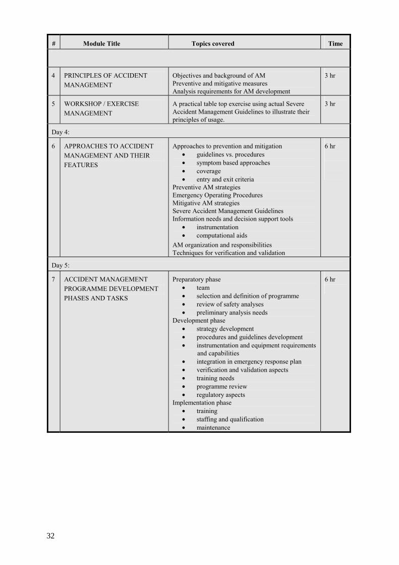
#
Module Title
Topics covered
Time
4
PRINCIPLES OF ACCIDENT MANAGEMENT
Objectives and background of AM Preventive and mitigative measures Analysis requirements for AM development
3 hr
5
WORKSHOP / EXERCISE MANAGEMENT
A practical table top exercise using actual Severe Accident Management Guidelines to illustrate their principles of usage.
3 hr
Day 4: 6
APPROACHES TO ACCIDENT MANAGEMENT AND THEIR FEATURES
Approaches to prevention and mitigation
• guidelines vs. procedures • symptom based approaches • coverage • entry and exit criteria
Preventive AM strategies Emergency Operating Procedures Mitigative AM strategies Severe Accident Management Guidelines Information needs and decision support tools
• instrumentation • computational aids
AM organization and responsibilities Techniques for verification and validation
6 hr
Day 5: 7
ACCIDENT MANAGEMENT PROGRAMME DEVELOPMENT PHASES AND TASKS
Preparatory phase
• team • selection and definition of programme • review of safety analyses • preliminary analysis needs
Development phase • strategy development • procedures and guidelines development • instrumentation and equipment requirements and capabilities • integration in emergency response plan • verification and validation aspects • training needs • programme review • regulatory aspects
Implementation phase • training • staffing and qualification • maintenance
6 hr
32

ANNEX II
EXAMPLES OF TYPICAL COMPUTATIONAL AIDS
Number Title Explanation
1 RCS INVENTORY DEPLETION AND CORE UNCOVERY
Guidance on time available to core uncovery for different types of events
2 CORE HEAT REMOVAL 2a MINIMUM FLOWRATE REQUIRED
FOR CORE QUENCH AND REFLOOD Injected coolant flow vs. RCS pressure showing achievable flow and flow required to quench and reflood overheated core
2b LONG TERM COOLING REQUIREMENTS
Required coolant flow vs. time after shutdown needed for decay heat removal by boiling
3 RCS PRESSURIZATION 3a RCS PRESSURIZATION — RCP
RESTART The amount of RCS pressurization to be expected following the core reflood due to main circulation pump restart
3b RCS PRESSURIZATION — REFLOODING SCENARIOS
The amount of RCS pressurization to be expected following the core reflood due to coolant injection
4 RCS VENTING AND DEPRESSURIZATION
Coolant outflow rate for different RCS vent paths
5 HYDROGEN GENERATION 5a HYDROGEN GENERATION FROM IN-
VESSEL CORE MATERIAL METAL-WATER REACTIONS
Magnitude of hydrogen sources from in-vessel oxidation
5b HYDROGEN GENERATION FROM EX-VESSEL CORE MATERIAL METAL-WATER REACTIONS
Magnitude of hydrogen sources from ex-vessel core material oxidation
5c HYDROGEN GENERATION FROM CONTAINMENT MATERIAL METAL-WATER REACTIONS
Magnitude of hydrogen sources from containment material oxidation
6 CORE MELT PROGRESSION Amount of core melt vs. time 7 CONTAINMENT CHALLENGE DUE TO
HYDROGEN COMBUSTION Containment pressure vs. hydrogen concentration showing flammable, non-flammable and severe challenge (=flammable with risk of containment damage) regions
9 CONTAINMENT VENTING Containment pressure vs. vent (gas) flow for all the containment vent paths
33

Minimum Injection Flow Rate Required to Quench Molten Core (4000 deg. F)
0
50
100
150
200
250
300
350
400
450
500
550
600
650
700
750
800
850
900
950
1000
2 4 6 8 10 12 14 16 18 20 22 24
Time Since Reactor Shutdown (hours)
Inje
ctio
n Fl
ow R
ate,
(gpm
)
30 minuterecovery
120 minuterecovery
Region of Expected Success
Region of Uncertain Success
More w ater required
FIG. II.1 Minimum injection flow rate required to quench molten core (4000 deg. F).
FIG. II.2 Minimum flow rate required to remove decay heat.
Example 2b
Minimum Flowrate Required to Remove Decay Heat
0
50
100
150
200
250
300
350
400
450
0 5 10 15 20
Time Since Reactor Shutdown (hrs)
Min
imum
Inje
ctio
n Fl
owra
te,
(gpm
)
Water Supplied viaECCS Recirculation
Water Supplied viaExtenal Source (e.g. RWST)
34

AN
NE
X II
I.
EX
AM
PLE
S O
F E
RO
OR
GA
NIZ
AT
ION
AL
CH
AR
TS
NPP
Krsk
o Em
erge
ncy R
espo
nse
Orga
nizat
ion C
hart
EOF
STAT
US
BOAR
DKE
EPER
EOF
DAT
ACO
MM
UNI
CAT
OR
EOF
COM
MU
NIC
ATOR
EOF
NETW
ORK
COM
MU
NIC
ATOR
EOF
TECH
NICA
L SU
PPOR
TCO
ORDI
NATO
R
TSC
ENV
IRON
MEN
TM
ONIT
ORI
NG
TEAM
SC
OOR
DINA
TOR
NEK
MOB
ILE
LABO
RAT
ORY
NEK
RAD
IOLO
GICA
LVE
HIC
LE
ENVI
RONM
ENT
RADI
OLOG
ICAL
ASS
ESM
ENT
COOR
DINA
TOR
EOF
PUBL
ICIN
FOR
MAT
ION
COO
RDI
NATO
R
PUBL
IC R
ESPO
NSE
& RU
MO
R C
ONTR
OLC
OOR
DINA
TOR
TEC
HNIC
ALIN
FOR
MAT
ION
COO
RDI
NATO
R
EOF
PUBL
ICIN
FORM
ATIO
N CE
NTER
COOR
DINA
TOR
EOF
ENGI
NEE
RIN
GTE
AM (4
)
EOF
ENGI
NEER
ING
TEAM
COO
RDIN
ATOR
EOF
ADM
INIS
TRAT
ION
AND
LOGI
STIC
SCO
ORDI
NATO
R
EOF
EMER
GENC
Y RE
SPON
SEAD
VISO
R
TSC
EMER
GENC
Y RE
SPON
SEAD
VISO
R
TSC
ADM
INIS
TRAT
ION
AND
LOGI
STIC
SCO
ORDI
NATO
R
TSC
STA
TUS
BOAR
DKE
EPER
TSC
DATA
COM
MUN
ICAT
OR
SAM
GEV
ALU
ATIO
NTE
AM
CO
RE P
HYSI
CSC
OOR
DINA
TOR
TSC
COM
MUN
ICAT
OR
TSC
COM
PUTE
RO
PERA
TER
TECH
NICA
L SU
PPOR
TCO
ORDI
NATO
R
TSC
HAB
ITAB
ILITY
TEC
HNIC
IAN
ENVI
RON
MEN
TAL
MON
ITO
RIN
G T
EAM
SC
OOR
DINA
TOR
NEK
RAD
. PR
OT.
MOB
ILELA
BOR
ATO
RY
NEK
RAD
. PR
OT.
SUPP
ORT
V E
HICL
E
RADI
ATIO
N PR
OTEC
TION
COOR
DINA
TOR
SHIF
TSU
PER
VISO
R
EVEN
TO
PERA
TION
SCO
ORD
INAT
OR
FIRE
PRO
TECT
ION
COO
RDIN
ATO
R
CHE
MIS
TRY
COO
RDIN
ATO
R
OPER
ATIO
NS S
UPPO
RTCO
ORDI
NATO
R
TSC
ING
ENIR
ING
STAF
F (4
)
DOC
UM
ENT.
TECH
NIC
IAN
INGE
NIRI
NG A
SSES
SMEN
TCO
ORDI
NATO
RSE
CURI
TYCO
ORDI
NATO
R
OSC
STAT
US B
OARD
KEEP
ER
OSC
COM
MUN
ICAT
OR
OSC
HABI
TABI
LITY
TECH
NICI
AN
DOS
IMET
RYG
ROU
P
ON-S
ITE
MON
ITO
RIN
GTE
AM
OFF
-SIT
EM
ONIT
ORI
NG
TEAM
PER
SON
ALD
ECO
NTAM
.TE
AM
EQU
IPM
ENT
DEC
ONT
AM.
TEAM
RADI
ATIO
NPR
OTEC
TION
TEAM
S FO
REM
AN
GR
OUP
1
GRO
UP
2
FIRS
T AI
DTE
AMFO
REM
AN
FIRE
BRIG
ADE
TEAM
1
FIRE
BRIG
ADE
TEAM
2
FIRE
BRIG
ADE
FORE
MAN
ELEC
TRIC
ALM
EINT
ENAN
CE
TEAM
ELEC
TRIC
ALM
EINT
ENAN
CETE
AM F
OREM
AN
MEC
HANI
CAL
MEI
NTEN
ANC
ETE
AM
MEC
HANI
CAL
MEI
NTEN
ANCE
TEAM
FORE
MAN
I & C
TEAM
I & C
TEAM
FORE
MAN
PASS
CHE
MIS
TRY
TEAM
PASS
/CHE
MIS
TRY
TEAM
FORM
AN
SHEL
TERI
NGM
EINT
ENAN
CETE
AM
OPER
ATIO
NAL
SUPP
ORT
CENT
ERCO
ORDI
NATO
R
MEI
NTEN
ANCE
COOR
DINA
TOR
TSC
PUBL
ICIN
FORM
ATIO
NCO
ORDI
NATO
R
EMER
GENC
Y DIR
ECTO
R
EOF D
IREC
TOR
FIG
. III.
1. N
PP K
rsko
Em
erge
ncy
Resp
onse
Org
aniz
atio
n ch
art.
35

Op
era
ting
C
rew
(S
yste
m
As
sess
me
nt)
Sh
ift
Ma
nag
er
Op
era
tion
s
Lia
son
(E
PG
/SA
G
Ass
essm
ent)
Re
acto
r E
ng
inee
r (C
ore
Ass
essm
ent)
Sa
fety
An
aly
sis
E
ng
inee
r (P
lan
t S
tatu
s A
sses
smen
t)
SP
DS
O
per
ato
r (P
ara
me
ter
Ass
essm
ent)
Op
era
tion
s S
up
ervi
sor
En
gin
eeri
ng
S
up
po
rt
I&C
En
gin
eer
Me
cha
nic
al
En
gin
eer
Ele
ctri
cal
En
gin
eer
EN
S
Com
mu
nic
ato
r
Ele
ctro
nic
Sta
tus
B
oar
d
Re
cord
er
En
gin
eeri
ng
S
up
erv
isor
Ra
dia
tion
P
rote
ctio
n
Su
pp
ort
S
taff
MID
AS
Op
erat
or
HP
N
Com
mu
nic
ato
r
Fie
ld
Te
amR
ad
io
Op
era
tors
Site
R
adia
tion
P
rote
ctio
n
Coo
rdin
ato
r
Se
curi
ty
Su
per
vis
or
Info
rma
tion
S
ervi
ces
R
ep
rese
nta
tive
Com
mu
nic
ato
rs
Ma
teri
al
Ma
na g
eme
nt
Coo
rdin
ato
r
Ad
min
istr
ativ
e
Coo
rdin
ato
r
Su
pp
ort
Se
rvic
es
Su
per
viso
r
Ele
ctri
cal
S
up
erv
isor
+
Ele
ctri
cia
ns
Ch
em
T
ech
s
Mec
han
ica
lS
up
erv
isor
+
Mec
ha
nic
s
WC
C/T
SC
/CR
Com
mu
nic
ato
r
I&C
S
up
erv
isor
+
I&C
Te
chs
Hea
lth
Ph
ysic
s T
ech
s
Hea
lth
Ph
y sic
s T
ech
s
Ch
emis
try
Tec
hs
OR
AL
/OD
EF
Su
per
viso
r
He
alth
P
hys
ics
Tec
hs
Sec
uri
ty
Fo
rce
OR
AA
S
up
ervi
sor
Hea
lth
Ph
ysic
s S
up
erv
iso
r
OS
C/W
CC
S
up
ervi
sor
Em
erg
ency
C
oor
din
ator
Qua
lity
Ass
uran
ce
Co
mm
uni-
ca
tors
Ons
ite/
Off
site
Acc
iden
t M
anag
emen
t T
eam
CR
/TS
C/W
CC
C
R B
ack
Pan
el
Cle
rica
l Sta
ff
FIG
. III.
2. E
mer
genc
y re
spon
se o
rgan
isatio
n sc
hem
e of
a ty
pica
l NPP
in U
SA.
36

Emergency Control Center of Forsmarks NPP
SGSpecialist
(initially 2 )
SED-
POPlant Operating
reactor f t
ML Monitoring L d
monitoring radiation prot. environm. chemistrdosimetrdecontaminati
RPRadiation Protection
radiological
CM
NPP rescue securittransportatio
CMCommunications
communicatio
INFO
Press information
INFInformation
informati
SESite Emergency
management,
FIG. III.3. Emergency Control Center of Forsmark NPP.
Emergency organization of Forsmarks NPP
Emergency Control Center(ECC)
Technical SupportCenter(TSC)
shift supervisoroperatorsradiation protectionchemistrymaintenanceetc
Unit Manager (UM)affected unit
personnel pool
Unit Managernot affected unit
personnel pool
Unit Managernot affected unit
Site Emergency Director (SED)
FIG. III.4. Emergency organization of Forsmark NPP.
37


ANNEX IV
EXAMPLES OF THE SEVERE ACCIDENT MANAGEMENT MANUALS
Nordic utilities, in particular, have adopted the practice to develop a SAM manual to support the personnel, who will make the critical SAM decisions. The objectives of the manual are twofold: first they aim at acquainting the AM personnel with all aspects of the severe accidents and their management, and secondly they have been written in such a way that they can support AM personnel also during the course of the severe accident. The SAM manuals can be utilized for the classroom training of the AM personnel in addition to the other technical basis documentation.
This Annex gives two examples of the SAM manuals developed for two NPPs: Forsmark NPP with BWR in Sweden and Loviisa NPP with WWER in Finland. There are some differences in the structure of these manuals, but the content as a whole is similar.
1. FORSMARK NPP
The structure of procedures and guidance reports in the Forsmark plant has been discussed in Ref. [IV.1]. During the accidents, there are specific EOPs used by the control room personnel. If the accident progresses beyond the validity of these EOPs, the accident management measures are guided by the knowledge of the emergency team. The main applicable tools for this phase are the Technical Support Document (TSD) at the unit level and the Manual for Severe Accident Management in the Emergency Crisis Centre (ECC). The manual contains the most important results and conclusions from the severe accident analyses performed. It also contains strategies for handling various accident situations and addresses important items relevant to AM. The manual is intended be used by the TSC staff within the ECC.
The first version of the manual was developed at the beginning of the 1990’s. Ref. [IV.1] discusses the upgrading of the manual. The aspects that have been emphasized are the strategies presented in the user friendly format. In the manual it was also reflected that certain short-term AM actions are of importance in the long-term perspective.
The main part of the manual is subdivided into four sections. The first section explains the use of the manual and the second one gives an overview of the current understanding of the severe accidents. The strategies for short-term measures in the Forsmark plant are then described in the third section subdivided into eight subsections. The strategies for long-term measures are described in the fourth section similarly subdivided into eight subsections. The remaining sections of the manual deal with various issues relevant for the ECC.
Contents of the Forsmark SAM Manual is as follows:
1. User's manual 2. Severe accidents — a general description 3. Short-term measures 4. Long-term measures 5. Instrumentation 6. Radiological environment after the accident 7. Safety measures for the personnel 8. AC power 9. Communication
39

10. Mobile equipment 11. Operation of non-damaged unit 12. Process parameters.
2. LOVIISA NPP
The first version of the manual is in use since May 2000. The publication with the title ‘SAM Manual: Training and Background Material for Severe Accident Management’ is applicable both for the TSC as well as for the off-site support during the accident. Clear structure increases its user friendliness.
After an introduction, there are seven sections in the publication devoted each to a separate severe accident safety function, which were defined specifically for Loviisa SAM. The safety functions are based on the requirement to ensure the containment integrity with a high confidence during severe accidents. Some of the safety functions (ensuring the containment integrity, primary circuit depressurization, in-vessel retention of the molten core, hydrogen management and containment overpressure protection with external sprays) have required significant plant modifications. The approach and its relation to the Finnish regulatory requirements have been explained in more detail in Ref. [IV.2].
The remaining sections of the Loviisa manual describe the recovery actions, which are bringing the plant to a long-term safe state, radiation protection and accidents during shutdown. In addition, there is an appendix describing the SAM instrumentation.
The contents of the Loviisa SAM Manual are:
1. Introduction 2. Ensuring the containment integrity and minimization of the releases 3. Depressurization of the primary circuit 4. Cooling the core or the core debris 5. Hydrogen management 6. Monitoring of the subcriticality 7. Prevention of the containment over-pressurization during a severe accident 8. Securing the fuel pool cooling 9. Recovery actions 10. Bringing the plant to the long-term safe state 11. Radiation protection issues 12. Accidents starting during shutdown conditions Appendix 1: The instrumentation related to the SAM safety functions.
REFERENCES
[IV.1] LÖWENHIELM, G., JANSSON, B., GUSTAVSSON, V., ‘New Ideas About Procedures and Handbooks for Severe Accident Management at the Forsmark Nuclear Power Plants’, The Fifth International Topical Meeting on Nuclear Thermal Hydraulics, Operations and Safety (NUTHOS-5), April 14–18, 1997, Beijing, China.
[IV.2] LUNDSTRÖM, P., TUOMISTO, H., THEOFANOUS, T.G., ‘Integration of Severe Accident Assessment and Management to Fulfil the Safety Goals for the Loviisa NPP’, International Topical Meeting on Probabilistic Safety Assessment PSA96, Park City, Utah, USA, September 29 – October 3, 1996.
40
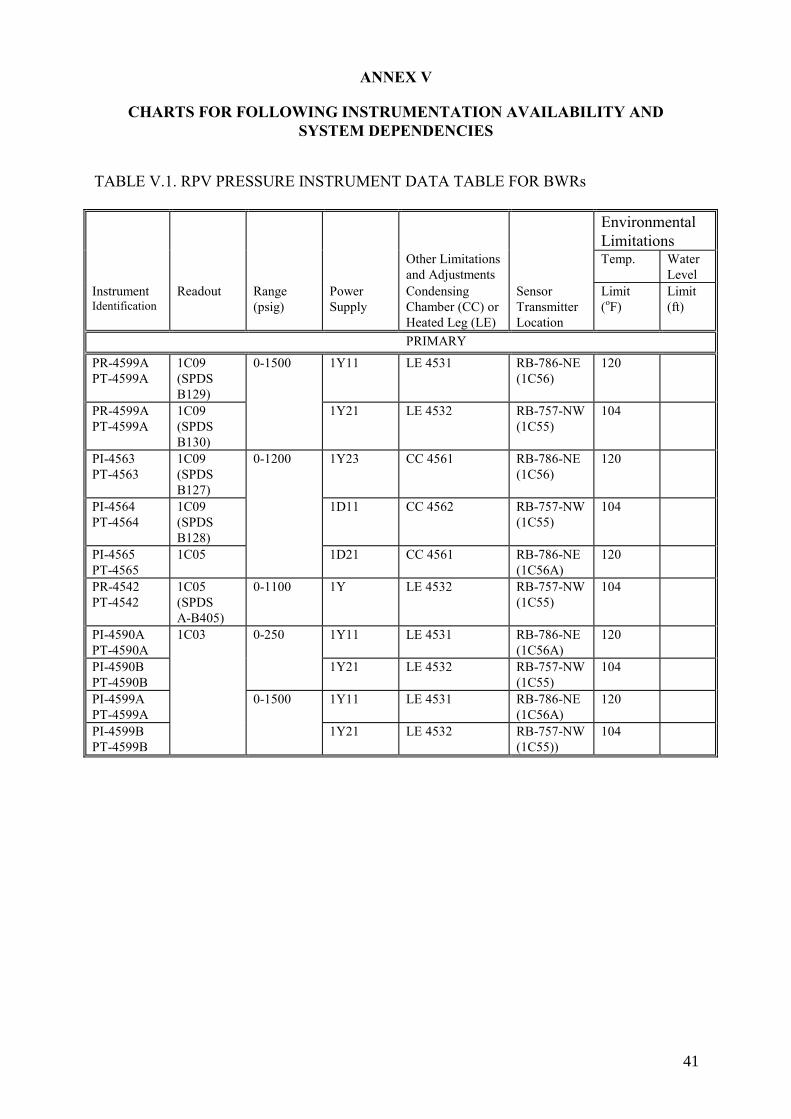
ANNEX V
CHARTS FOR FOLLOWING INSTRUMENTATION AVAILABILITY AND SYSTEM DEPENDENCIES
TABLE V.1. RPV PRESSURE INSTRUMENT DATA TABLE FOR BWRs Environmental
Limitations Other Limitations
and Adjustments Temp. Water
Level Instrument Identification
Readout Range (psig)
Power Supply
Condensing Chamber (CC) or Heated Leg (LE)
Sensor Transmitter Location
Limit (oF)
Limit (ft)
PRIMARY PR-4599A PT-4599A
1C09 (SPDS B129)
0-1500 1Y11 LE 4531 RB-786-NE (1C56)
120
PR-4599A PT-4599A
1C09 (SPDS B130)
1Y21 LE 4532 RB-757-NW (1C55)
104
PI-4563 PT-4563
1C09 (SPDS B127)
0-1200 1Y23 CC 4561 RB-786-NE (1C56)
120
PI-4564 PT-4564
1C09 (SPDS B128)
1D11 CC 4562 RB-757-NW (1C55)
104
PI-4565 PT-4565
1C05 1D21 CC 4561 RB-786-NE (1C56A)
120
PR-4542 PT-4542
1C05 (SPDS A-B405)
0-1100 1Y LE 4532 RB-757-NW (1C55)
104
PI-4590A PT-4590A
1C03 0-250 1Y11 LE 4531 RB-786-NE (1C56A)
120
PI-4590B PT-4590B
1Y21 LE 4532 RB-757-NW (1C55)
104
PI-4599A PT-4599A
0-1500 1Y11 LE 4531 RB-786-NE (1C56A)
120
PI-4599B PT-4599B
1Y21 LE 4532 RB-757-NW (1C55))
104
41


ANNEX VI
WORK CHARTS FOR AM ACTION PERFORMANCE
This is an excerpt of a work chart for AM actions performance that is used by NPP Krško in Slovenia. Inside NPP Krško ERO such work charts are developed for Emergency Director position and Shift Engineer position. Work charts are developed consistently with plant Emergency Preparedness Plan (EPP) documentation, i.e. Emergency Implementing Procedures (EIPs) and SAMGs.
Legend
Step/Location/Procedure
• Procedure step number which describes the action
• Abbreviations (MCR, TSC, EOF) show which location is responsible for performing an action. If more than one are listed it means that responsibility for performance of corresponding action transfers with the operability status of emergency organization (e.g. MCR-TSC-EOF means that responsibility for the action transfers from MCR to TSC and then to EOF).
• Procedure number in which describes the actions.
Action
• Determines activities to be performed in order to cope with the condition.
Emergency Director
• Describes main actions to be taken by emergency director
Other Personnel Involved
• Shows other personnel involved which is responsible to perform their actions to support to high level action described in “Action” section. TSC position responsible for performance of such action is shown in parenthesis ( ) and EOF responsible position is shown in brackets [ ].
Action not taken IF
• In this column emergency class level(s) and/or other conditions are listed to indicate when performance of particular action is not applicable.
Performed (Date, Time, Signature)
• Emergency director fills in the data and signs when the action comes in effect.
43

TAB
LE V
I.1. E
XA
MPL
E O
F A
WO
RK
CH
AR
T FO
R A
M A
CTI
ON
S A
T K
RSK
O N
PP
AC
TIO
NS
DU
RIN
G E
ME
RG
EN
CY
(E
mer
genc
y D
irec
tor)
IMM
ED
IAT
E A
CT
ION
S (if
nec
essa
ry)
Step
L
ocat
ion
Proc
edur
e
Act
ion
Em
erge
ncy
Dir
ecto
r O
ther
Per
sonn
el In
volv
ed
Act
ion
not
take
n IF
Pe
rfor
med
(D
ate,
Tim
e,
Sign
atur
e)
6.5.
2 M
CR-T
SC
EIP-
17.0
41
Evac
uatio
n of
lim
ited
plan
t are
a or
bui
ldin
g 1.
C
omm
ands
eva
cuat
ion
and
dete
rmin
es:
• A
rea
to b
e ev
acua
ted;
•
Ass
embl
y po
int f
or e
vacu
ees;
•
Spec
ial m
easu
res t
o be
car
ried
out.
2.
Info
rms s
hift
engi
neer
to a
nnou
nce
evac
uatio
n ov
er p
lant
pag
ing
syst
em.
3.
Info
rms s
ecur
ity sh
ift su
perv
isor
to c
o-or
dina
te e
vacu
atio
n..
4.
Info
rms H
P te
chni
cian
(if n
eces
sary
) to
perfo
rm n
eces
sary
radi
atio
n pr
otec
tion
mea
sure
s. 5.
Fo
llow
s-up
on
cond
uct o
f eva
cuat
ion
with
se
curit
y sh
ift su
perv
isor
. 6.
D
ecla
res c
ondi
tions
for d
isba
ndin
g th
e as
sem
bly
poin
t. 7.
D
ecla
res n
orm
al c
ondi
tions
in a
ffect
ed
(eva
cuat
ed) a
rea.
Shift
Eng
inee
r •
Ann
ounc
es e
vacu
atio
n ov
er p
lant
pa
ging
syst
em
Secu
rity
Shi
ft S
uper
viso
r •
Co-
ordi
nate
s the
con
duct
of
evac
uatio
n •
Co-
ordi
nate
s sec
urity
per
sonn
el
activ
ities
dur
ing
evac
uatio
n •
Prep
ares
the
list o
f eva
cuee
s and
pr
ovid
es it
to
Emer
genc
y D
irect
or
HP
Tec
hnic
ian
• Pe
rform
s rad
iolo
gica
l sur
vey
and
deco
ntam
inat
ion
of e
vacu
ees;
•
Det
erm
ines
radi
olog
ical
con
ditio
ns
in a
ffect
ed a
rea
/
44
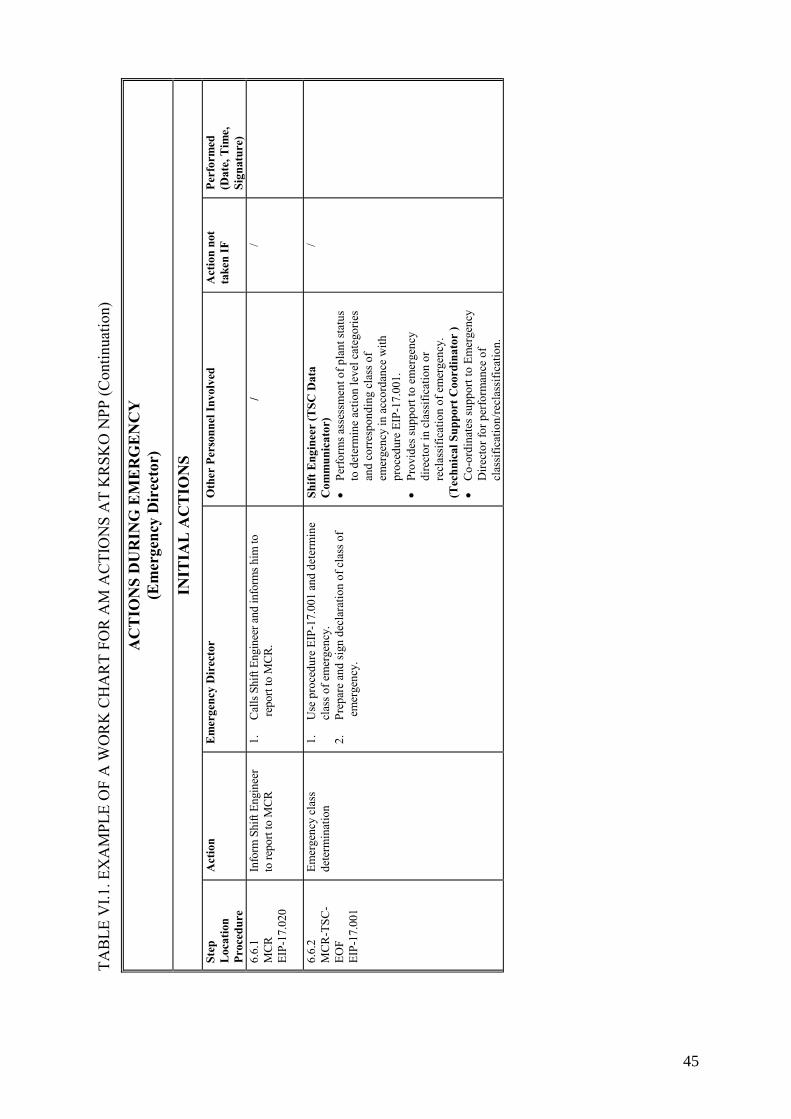
TAB
LE V
I.1. E
XA
MPL
E O
F A
WO
RK
CH
AR
T FO
R A
M A
CTI
ON
S A
T K
RSK
O N
PP (C
ontin
uatio
n)
AC
TIO
NS
DU
RIN
G E
ME
RG
EN
CY
(E
mer
genc
y D
irec
tor)
INIT
IAL
AC
TIO
NS
Step
L
ocat
ion
Proc
edur
e
Act
ion
Em
erge
ncy
Dir
ecto
r O
ther
Per
sonn
el In
volv
ed
Act
ion
not
take
n IF
Pe
rfor
med
(D
ate,
Tim
e,
Sign
atur
e)
6.6.
1 M
CR
EIP-
17.0
20
Info
rm S
hift
Engi
neer
to
repo
rt to
MC
R
1.
Cal
ls Sh
ift E
ngin
eer a
nd in
form
s him
to
repo
rt to
MC
R.
/ /
6.6.
2 M
CR
-TSC
-EO
F EI
P-17
.001
Emer
genc
y cl
ass
dete
rmin
atio
n 1.
U
se p
roce
dure
EIP
-17.
001
and
dete
rmin
e cl
ass o
f em
erge
ncy.
2.
Pr
epar
e an
d si
gn d
ecla
ratio
n of
cla
ss o
f em
erge
ncy.
Shift
Eng
inee
r (T
SC D
ata
Com
mun
icat
or)
• Pe
rform
s ass
essm
ent o
f pla
nt st
atus
to
det
erm
ine
actio
n le
vel c
ateg
orie
s an
d co
rres
pond
ing
clas
s of
emer
genc
y in
acc
orda
nce
with
pr
oced
ure
EIP-
17.0
01.
• Pr
ovid
es su
ppor
t to
emer
genc
y di
rect
or in
cla
ssifi
catio
n or
re
clas
sific
atio
n of
em
erge
ncy.
(T
echn
ical
Sup
port
Coo
rdin
ator
) •
Co-
ordi
nate
s sup
port
to E
mer
genc
y D
irect
or fo
r per
form
ance
of
clas
sific
atio
n/re
clas
sific
atio
n.
/
45

TAB
LE V
I.1. E
XA
MPL
E O
F A
WO
RK
CH
AR
T FO
R A
M A
CTI
ON
S A
T K
RSK
O N
PP (C
ontin
uatio
n)
6.6.
6 M
CR-T
SC-
EOF
EIP-
17.0
61
Follo
w d
ata
abou
t ra
diol
ogic
al c
ondi
tions
an
d as
sess
radi
olog
ical
sta
tus a
roun
d th
e pl
ant
1.
Base
d on
radi
olog
ical
con
ditio
ns p
erfo
rms
asse
ssm
ent o
f act
ual o
r pot
entia
l ra
diol
ogic
al re
leas
es to
the
envi
ronm
ent.
2.
Follo
ws s
ituat
ion
on ra
dioa
ctiv
e re
leas
es
disp
ersio
n.
Shift
Eng
inee
r
(Off-
site
Mon
itori
ng T
eam
Co-
ordi
nato
r)
• Fo
llow
s met
eoro
logi
cal c
ondi
tions
an
d di
sper
sion
of ra
dioa
ctiv
e re
leas
es;
• Ca
lcul
ates
dos
e ra
tes i
n th
e en
viro
nmen
t usin
g EI
S ap
plic
atio
n or
m
anua
lly;
• In
form
s em
erge
ncy
dire
ctor
abo
ut
radi
olog
ical
stat
us.
(Rad
iatio
n Pr
otec
tion
Co-
ordi
nato
r)
• Fo
llow
s ra
diol
ogic
al c
onse
quen
ces
in
envi
ronm
ent;
• In
form
s em
erge
ncy
dire
ctor
abo
ut th
e sta
tus.
/
46

TAB
LE V
I.1. E
XA
MPL
E O
F A
WO
RK
CH
AR
T FO
R A
M A
CTI
ON
S A
T K
RSK
O N
PP (C
ontin
uatio
n)
6.
6.18
M
CR-T
sC
SAG
-17.
001
Eval
uatio
n of
co
nditi
ons a
nd a
ctio
n de
term
inat
ion
base
d on
SA
MG
s.
1.
Mak
es d
ecisi
ons a
nd is
sues
writ
ten
orde
r to
impl
emen
t act
ions
bas
ed o
n ev
alua
tion
per
SAM
Gs.
Shift
Eng
inee
r)
(SA
MG
Eva
luat
ion
Team
in T
SC)
• A
naly
se th
e sit
uatio
n an
d re
com
men
d ac
tions
to e
mer
genc
y di
rect
or b
ased
on
SA
MG
. (O
SC T
eam
s For
emen
) •
Eval
uate
sugg
este
d ac
tions
and
pr
ovid
e su
ppor
t to
emer
genc
y di
rect
or
with
rele
vant
info
rmat
ion
for d
ecisi
on
mak
ing
rela
ted
to im
plem
enta
tion.
(T
echn
ical
Sup
port
Co-
ordi
nato
r in
TS
C)
• Co
-ord
inat
es st
atus
eva
luat
ion
in
acco
rdan
ce w
ith S
AM
Gs;
• Ba
sed
on e
valu
atio
n pe
r SA
MG
S re
com
men
ds a
ctio
ns to
em
erge
ncy
dire
ctor
UN
USU
AL
EVEN
T A
LERT
SI
TE
EMER
GEN
CY
47

TAB
LE V
I.1. E
XA
MPL
E O
F A
WO
RK
CH
AR
T FO
R A
M A
CTI
ON
S A
T K
RSK
O N
PP (C
ontin
uatio
n)
AC
TIO
NS
DU
RIN
G E
ME
RG
EN
CY
(E
mer
genc
y D
irec
tor)
SUB
SEQ
UE
NT
AC
TIO
NS
Step
L
ocat
ion
Proc
edur
e
Act
ion
Em
erge
ncy
Dir
ecto
r O
ther
Per
sonn
el In
volv
ed
Act
ion
not
take
n IF
Pe
rfor
med
(D
ate,
Tim
e,
Sign
atur
e)
6.7.
1 TS
C EI
P-17
.022
Act
ivat
ion
of T
SC a
nd
trans
fer o
f re
spon
sibi
litie
s fro
m
MC
R to
TSC
.
1.
In a
ccor
danc
e w
ith p
roce
dure
EIP
-17.
022
Tech
nica
l sup
port
cent
re –
act
ivat
ion,
pe
rform
act
ions
to a
ctiv
ate
TSC.
2.
C
o-or
dina
te tr
ansf
er re
spon
sibili
ties f
or
impl
emen
tatio
n of
act
ions
from
MCR
to
TSC.
TPC
Per
sonn
el
• Ta
ke a
ctio
ns to
act
ivat
e TS
C in
ac
cord
ance
with
pro
cedu
re E
IP-
17.0
22 a
nd a
ssum
e re
spon
sibili
ties
for c
ontin
uatio
n of
act
ions
that
wer
e be
fore
co-
ordi
nate
d fro
m M
CR.
UN
USU
AL
EVEN
T
48

ANNEX VII
EXAMPLES OF COMPUTERIZED TOOLS
In several countries there is ongoing research, development and implementation of various computerized tools and expert systems for accident management and source term predictions to be used by control room operators, TSCs at the site and national emergency teams. A few examples of such systems are presented here.
EDF
Electricité de France (EDF) has developed a set of tools and simplified models, named TOUTEC and CRISALIDE, which are aimed to be used by the French Utility National Crisis Team in order to perform the task of diagnosis and prognosis during an emergency situation [VII.1]. The method is based on the diagnosis of the state of the safety barriers and on the prognosis of their behaviour.
At a first level, the software TOUTEC is intended to complement the handbook of crisis team members with simplified calculation models and predefined relationships. The main items are the calculation of the primary circuit break size and the evaluation of hydrogen burning. The set of models named CRISALIDE is devoted to evaluate the following critical parameters: delay before core uncovery, containment pressure behaviour and source term. With these models, it is possible to take into account combinations of boundary conditions according to safety and auxiliary systems availability and operator's actions. The CRISALIDE models and man-machine interface TOUMEC are running under WINDOWS environment on a personal computer.
IPSN
The Institute for Nuclear Safety and Protection (IPSN, at present IRSN) in France has developed a methodology to evaluate the plant status and to estimate the evolution of the accident in French PWRs [VII.2]. Two systems are used: SESAME for the evaluation of the plant status and potential releases and CONRAD for radiological consequences calculations. The diagnosis of the status of a PWR during an accident is based on the analysis of plant-specific data. The information transmitted from the plant is used by the expert team to assess the status of different safety functions and barriers. The specific tools of the SESAM system are used to quantify parameters such as break size or potential fission product release within or outside the plant. The prognosis of the evolution of safety functions and barriers is based on the assessment of the current and future availability of the safety systems and on extrapolations to forecast the evolution of the accident (time to core uncovery and core degradation, fission product releases prognosis, etc).
CAMS
The objective of CAMS (Computerized Accident Management Support) is to provide support in accident states and normal plant states [VII.3]. This support is offered in identification of the plant state, in assessment of the future development of the accident, and in planning accident mitigation strategies. The CAMS system is being developed as a research activity at the OECD Halden Reactor Project in Norway. The first CAMS prototype was completed in 1995.
49
CAMS consist of a data acquisition module, a signal-validation module, a tracking simulator, a predictive simulator, a state-identification module, a probabilistic safety assessment module, and a man-machine interface module. The work of these modules is coordinated by a module called the system manager. The data acquisition module operates as an interface between CAMS and the monitored process. In addition, there are the strategy generator and the critical function monitor. However, these two modules have not been integrated into the present version of the CAMS prototype.
The tracking simulator module gives an estimation of the values that are not directly measured, calculates the initial values that are needed for the predictive simulator, and gives support in the validation of the signals by calculating values of certain parameters. The predictive simulator module predicts the evolution of the state of the plant, being faster than the real process. Finally, the plant state identification module gives information about the state of the plant, the state of the systems (their availability), and the state of the critical safety functions (heat sinks, core cooling, reactivity control, and containment integrity).
The purpose of the PSA module is to provide on-line accident prevention and mitigation strategies for a nuclear power plant. The module contains plant specific PSA data, comprising event trees, failure probabilities, etc. The core damage frequency is re-calculated based on the current state of the plant and the pre-calculated PSA Level 1.
ADAM
The WINDOWS-based ADAM (Accident Diagnostic and Management) system has been developed by Energy Research, Inc. in USA for analysis of selected plant data, following accidents, to arrive at symptom-based diagnostics of potential nuclear power plant accidents [VII.4]. It operates in two modes:
1. On-line accident diagnostics/monitoring mode. In this mode, selected plant parameters (as measured by plant sensors), arriving into
ADAM at a pre-specified frequency, are used to assess the margins to core damage, containment failure, vent actuation, and hydrogen combustion (through appropriate alarms). In addition, the state of reactor, containment, and auxiliary building (if applicable), are assessed using a symptom-based diagnostics logic that is developed on a plant-specific basis.
2. Accident management and simulation mode. In this mode, ADAM can be used to simulate various operational and severe accident scenarios to determine the potential impact of the available severe accident management strategies (or Emergency Operating Procedures) on the evolution of the accident in progress. Alternatively, ADAM can also be used as an accident analysis tool. The simulation code can also be used to generate data for the diagnostic mode to assist in the visual display of the accident. The plant initial conditions and information about the type of the accident is user-specified.
STM
The STM (Source Term Module) software, developed by NNC in the UK, employs Bayesian analysis techniques, in particular belief network analysis to calculate the conditional probabilities and the potential magnitude of a release of activity into the environment [VII.5]. STM had been designed to provide a rapid indication of the most likely source terms, prior to a release occurring, using plant data which will be available to the plant operator whilst
50
following emergency procedures to control the critical safety functions. The module is stand-alone and PC based and does not require expert knowledge of severe accidents or fission product behaviour. It has been developed using PSA Level 1 and Level 2 results for PWR Sizewell B plant in the UK. Source term categories are defined for the 3 release points (primary circuit/containment, secondary circuit and the auxiliary circuits) with information provided on the quantity and timing of the release.
REFERENCES
[VII.1] SEKRI, A., DE MAGONDEAUX, B., PIZA, F., AUGE, AC., ‘PWRs Simulation Models used by EDF/SEPTEN Crisis Team’, Second OECD Specialist Meeting on Operator Aids for Severe Accident Management (SAMOA-2), Lyon, France, September 8–10, 1997.
[VII.2] WINTER, D., AGATOR, J.M., ‘Methodology and Software Tools used by IPSN Crisis Centre Experts during an Emergency in a French PWR’, Second OECD Specialist Meeting on Operator Aids for Severe Accident Management (SAMOA-2), Lyon, France, September 8–10, 1997.
[VII.3] FANTONI, P.F., SÖRENSSÖN, A., MAYER, G., ‘CAMS: A Computerized Accident Management System for Operator Support during Normal and Abnormal Conditions in Nuclear Power Plant’, Second OECD Specialist Meeting on Operator Aids for Severe Accident Management (SAMOA-2), Lyon, France, September 8–10, 1997.
[VII.4] ESMAILI, H., ORANDI, S. VIJAYKUMAR, R., KHATIB-RAHBAR, M., ZUCHUAT, O., AND SCHMOCKER, U., ‘ADAM: An Accident Diagnostics, Analysis and Management System’, G. Guedes Soares (ed), Advances in Safety & Reliability, (1997) 257
[VII.5] ROJAS-PALMA, C., SOHIER, A., SMEDLEY, CH., GRINDON, E., CLARK, D., DUTTON, M., ‘On and Off-site Source Term Estimation during Nuclear Emergencies’, 7th Topical Meeting on Emergency Preparedness and Response, California, USA, September 1999.
51


ANNEX VIII
EXAMPLE OF TABLETOP SCENARIOS AND OBJECTIVES
1. OBJECTIVES
1. Given access to the SAMG documentation and given the information and data specified in this scenario, the EVALUATOR shall be able to use the guidance provided in the SAMG to perform the evaluations required by that process so that the DECISION MAKER will be able to make process based decisions.
2. Apply the entry criterion and exit conditions for applicable guidelines. • Recognize the criteria for entering applicable guidelines. • Prior to exiting a guideline, ensure that any applicable exit conditions are met
and that a process to follow long term concerns is implemented.
3. Determine which strategies are available and applicable under current plant conditions.
4. Identify any negative impacts potentially associated with the available strategies and evaluate action to mitigate negative impacts.
5. Decide whether to implement a strategy and which mitigative action, if any, to take.
6. Specify instructions for the control room pertaining to strategy implementation and mitigative action.
• Preferred line-up; • Limitations.
7. Verify implementation of instructions pertaining to strategies and mitigative actions.
8. Monitor negative impacts and decide whether to take additional mitigative action.
9. Check the effectiveness of an implemented strategy and determine whether additional strategies should be attempted.
10. Evaluate data and interpret instrumentation readings given that severe accident conditions exist.
11. Use computational aids as needed.
12. Actively participate in the scenario critique process.
13. Utilize effective communication techniques to coordinate emergency information/actions with the Control Room IMPLEMENTORS and other ERO staff.
53

2. TURNOVER INFORMATION — UNIT 2 SHIFT SUPERVISOR TO ON-CALL ED
• An ALERT was declared l hour ago due to a .07g seismic event. Both units remained at 100%.
• All off-site notifications have been made for the Alert.
• A Site Area Emergency was declared 20 minute ago following an after shock that resulted in a LB LOCA, an LOSP, and a loss of .1 Unit 1 AC Power.
• Suspected SU XFMER and Diesel Generator damage.
• All offsite notifications have been made for the SAE.
• Unit 2 is tripped and stable in accordance with the procedure ESP-0.1; 2B DG is supplying all needed Unit 2 loads.
• Unit 1 is currently under the procedure FRP-C.1 with CETCs l300 degrees F and continuing to rise.
• Following the aftershock, the procedure ECP-0.0 was entered due to no Unit 1 Diesel Generators initially being available
- B train has been restored; A train is still de-energized.
- DG 1-2A failed to start due to damage to its fuel supply system.
- DG 1C failed to start because it had previously been tagged out for slow start maintenance and is currently not available.
- The lB DG did automatically start following the LOSP but DG08 did not automatically close due to a suspected B1G sequencer failure; B train loads were manually shed and the 1G and 1L buses were manually energized by closing DG08 and DG02.
- Switchhouse does not know how long the grid will be unavailable; the procedure FNP has priority for power restoration.
- A Reentry team is working to return the 1C and 1-2A DGs to service.
• Following the reenergization of the B train, ECP-0.0 was exited
• Procedural transition has been through the procedures ECP-0.0, FRP-P. 1, FRP-Z. 1, EEP-0, FRP-C.2, to FRP-C1. Currently at FRP-C.l step 22 preparing to transition to SACRG-1.
• Adverse CTMT conditions exist.
• SG levels are being maintained by the TDAFW pump.
• The 1A CCW pump, 1C Charging pump, and the 1D and lE SW pumps have been started manually from the Control Room. Charging flow indicated on FI-943 is erratic.
54

3. DESCRIPTION OF THE SCENARIO 1A
TRANSIENT SAMG1R1 .WK4/SEQB03/TRE271H
Big picture A transient occurs due to flooding of the cable spreading room. All ECCS injection is
unavailable because of ESFAS actuation failure. AFW fails, and all fan coolers and containment spray do not operate. Seal cooling is provided to the RCPs, so a consequential seal LOCA does not occur. The containment is isolated.
Narrative summary While operating at 100% power a break in the pre-action fire sprinkler system piping
occurs in the Cable Spreading Room. Flooding begins because the fire protection piping has been left pressurized due to an earlier fire protection system problem. The unisolated flood is conservatively postulated to cause a short-to-ground of the power supplies to both trains of protection and control panels and termination cabinets in the room. This results in an automatic reactor trip/turbine trip at time 0. Due to the flooding no other protective actions or equipment operate. The short-to-ground of the DC power supply in the cabinets causes a trip of the cabinet DC power supply breakers which effectively generates a close signal for solenoids resulting in a loss of air to air operated components, including CTMT isolation dampers. Containment is effectively isolated and no release occurs. CTMT fan coolers and containment spray are also affected by the flooding and will not function. The flooding results in loss of AFW. The operators are expected to attempt to start AFW from the Hot Shutdown panels. Alternate alignment of condensate, and feed and bleed are unsuccessful and the SGs boil dry at approximately 25 minutes (actual time is 60 minutes). The loss of decay heat removal capability results in increasing core temperatures. PZR relief to the PRT results in PRT rupture disc failure at 35 minutes. Core uncovery occurs in approximately 40 minutes (actual time is 100 minutes) followed by the onset of core melt (>1200F) at 50 minutes (actual time is 112 minutes). CETC failure occurs at 65 minutes (actual time is 180 minutes) with the last reading at 2594 ºF. Vessel failure occurs at approximately 85 minutes (actual time is 185 minutes) from the start of the transient resulting in high pressure melt ejection.
The core damage frequency for this accident which was run as part of the IPE back-end analysis is 5.406e-6 yr-1. Maximum CTMT pressure (with no successful operator actions) is 88 psig (52 psig for the time period of this scenario data) and CTMT failure occurs> 48 hours from the start of the transient with a maximum cavity concrete ablation of 6 ft.
55
4. DESCRIPTION OF THE SCENARIO lB
SBO-SAMG5R1/SEQB47/BOE24IH
Big picture A single-unit LOSS OF ALL AC results in seal LOCAs on all 3 pumps with no RCS
makeup available. The turbine-driven AFW pump provides decay heat removal until power is recovered at 75 minutes. Containment spray (both trains) is assumed to initiate when power is recovered, but neither train of SW or CCW is restored. ECCS injection and the containment fan coolers therefore do not operate. Spray recirculation is conservatively assumed to fail. The containment is isolated.
Narrative summary While operating at 100% power a single-unit LOSP with loss of 4160 V buses F and G
with failures of the associated bus DGs results in LOSS OF ALL AC (SBO). An automatic reactor/turbine trip occurs at time 0 due to complete loss of forced RCS flow. The SBO DG is initially unavailable. Due to loss of seal injection and CCW cooling to the RCP seals a seal LOCA of 480 gpm/pump (modelled as a 0.00375 ft2 break in each of three intermediate legs) occurs at 5 minutes resulting in an SI actuation signal generation. The containment is isolated due to the SI but due to no electrical power available to the ESF pumps PZR level continues to decrease until empty at approximately 10 minutes. The turbine-driven AFW pump starts upon loss of all AC and provides SG makeup to allow for decay heat removal until power is recovered. The continued loss of RCS inventory without makeup results in increasing core temperatures. Core uncovery occurs in approximately 30 minutes (actual time is 96 minutes) followed by the onset of core melt (>l2000F) at 45 minutes (actual time is 112 minutes). The SBO DG becomes available at 50 minutes however the failure of the 1A CCW pump and the B train SW pumps prevent operation of HHSI and LHSI. CETC failure occurs at 60 minutes (actual time is 210 minutes). Vessel failure occurs at approximately 110 minutes (actual time is 252 minutes) from the start of the transient resulting in high pressure melt ejection. Note that spray recirculation is conservatively assumed to fail at 115 minutes (actual time is 260 minutes).
The core damage frequency for this accident which was run as part of the IPE back-end analysis is 5.035e-7 yr-1. Maximum CTMT pressure (with no successful operator actions) is 25 psig and CTMT failure occurs >48 hours from the start of the transient with a maximum cavity concrete ablation of 5.8 ft.
56

5. DESCRIPTION OF THE SCENARIO 2A
TRANSIENT- SAMG7R1.WK4//RVE21lL
Big picture An ATWT results in core damage, high RCS pressure and RPV rupture. The RPV
rupture is modelled as a 4 ft2 break in the vessel wall. (Note that this sequence bounds those cases where pressurized thermal shock (PTS) could be postulated to fail the RPV. Since this ii a break beyond the capability of the ECCS, ECCS operation is not credited, but all three accumulators do inject. One CTMT fan cooler and one train of spray operate. Spray recirculation is assumed to be unsuccessful. Note that this sequence leads to substantial basemat ablation which could be mitigated by continued vessel injection/recirculation. The containment is isolated.
Turnover A TSC/EOF table top drill is being conducted in the TSC as part of the EPP training
programme. Both units are at 100% power.
Narrative summary Unit 1 experiences a fault on the lF 4l60V bus resulting in a Main Turbine trip and loss
of both SGFPs. The Steam Dumps do not operate. The Reactor does not trip automatically and can not be tripped from the Control Room. Continued power operation without the main feed system results in the lB and 1C SGs boiling dry (lA RCP trips due to the electrical fault and therefore the 1A SG is not steaming). At 4.5 minutes core temperatures exceed 1200F and transition to the SAMGs occurs. At 5 minutes, RCS pressure is 2550 PSIG when the reactor is tripped locally by securing the operating CRDM set. At approximately 5.5 minutes the reactor pressure vessel is believed to fail due to the high pressure and corium relocation to the bottom reactor pressure vessel head. CETC indication fails at this time also. CTMT pressure reaches 50 PSIG during the transient The Control Room Crew will proceed thru step 18 of SACRG-1 prior to the TSC reporting that they are staffed and monitoring the SAMGs. Success paths will include manual alignment of HHSI flow from the 1C Charging Pump, SG refill, CTMT flooding, manual operation of CTMT spray and fans. The TSC is expected to utilize SAG1, 3,4,6, and 8 as well as SAEG-l. No release occurs.
The core damage frequency for the RPV failure accident which was run as part of the IPE back-end analysis is 9.97e-8 yr-1. Maximum CTMT pressure for the RPV failure without the ATWT (with no successful operator actions) is 32 psig and CTMT failure occurs >45 hours from the start of the transient with a maximum cavity concrete ablation of 7 ft.
57
6. DESCRIPTION OF THE SCENARIO 2B
LBLOCA- SAMG3R1/LLE27IL
Big picture A seismic event causes a large LOCA to occur with failure of both trains of ESF to
automatically initiate an SI signal. A subsequent LOSP with diesel/sequencer failures results in multiple failures of ESF equipment including all fan coolers and CTMT Spray. The LB LOCA is modelled as a 3 ft2 break in the cold leg. ECCS injection using one charging pump will occur and all three accumulators will inject. The containment is isolated. The containment is predicted to fail at 37 hours because of over-pressurization.
Turnover An ALERT has been declared due to a .07g seismic event which occurred 2 hours ago.
DG 1C is tagged out of service for slow start investigation/maintenance. The TSC and EOF are staffed and operational. Both Units are at 100% power.
Narrative summary An aftershock results in a LB LOCA and a Unit 1 LOSP due to SU XFMER damage.
DG 1C had previously been tagged out for slow start maintenance and the l-2A DG fails due to loss of it’s fuel supply system resulting in loss of all A train components. The 1B DG is running following the LOSP but due to damage to the B1G sequencer no loads were shed and the DG has not re-energized the 1G 4160V bus. The crew will reenergize the B train using ECP.0.O and subsequently will transition thru FRP-P.1 and FRP-Z. 1 into EEP-0. The 1A CCW pump and 1C Charging pump will be restarted by the crew; no other B train components can be started from the Control Room. The lB RHR pump can be made available once control power fuses are replaced. The lengthy time of core uncovery results in increasing CETC temperatures and subsequent transition to FRP-C.2 and C. 1. Instrument air is available from Unit 2 and SG depressurization is allowed per FRP-C. 1. Despite FRP-C. 1 actions, CETC’s continue to rise resulting in entry into SACRG1 at 18 minutes. At step 8 the TSC assumes responsibility for SAMG implementation and the crew transitions to SACRG2. The TSC continues DFC usage and implementation of SAG 3,4,6, and 8. CETCs fail at 28 minutes. Due to CTMT spray and fan coolers remaining unavailable CTMT pressure rises to greater than 92 psig at 50 minutes and the TSC transitions into SCG2 where venting is the only success path. At 65 minutes the crews will be informed that time has elapsed and that a negative 5 psig now exists in the CTMT resulting in TSC transition into SCG4.
The core damage frequency for this accident which was run as part of the IPE back-end analysis is 3.9e-6 yr-1. Maximum CTMT pressure (with no successful operator actions) is 105 psig and CTMT failure occurs>36.8 hours from the start of the transient with a maximum cavity concrete ablation of 6.7 ft.
58

CONTRIBUTORS TO DRAFTING AND REVIEW
Frid, W. SKI, Sweden
Khatib-Rahbar, M. Energy Research Inc., United States of America
Mišák, J. International Atomic Energy Agency Pribozič, F. NPP Krško, Slovenia
Tuomisto, H. Fortum Engineering Ltd, Finland
Vayssier, G.L.C.M. Nuclear Safety Consultancy, Netherlands
Consultants Meeting
Vienna, Austria: 11–15 December 2000
59