overview of loads on and in structures / machines
DESCRIPTION
Overview of Loads ON and IN Structures / Machines. Overview of Various Stress Patterns. Solution of Example Problem 4.3. Step 1 – Construct shear&moment diagrams Step 2 – Find d min =0.90in to resist allowable =35,000psi at section where M max =2500in-lb - PowerPoint PPT PresentationTRANSCRIPT
MAE 343 - Intermediate Mechanics of Materials
Tuesday, Sep. 14, 2004
Textbook Section 4.4
Overview of Structural Analysis for Beams and Shafts
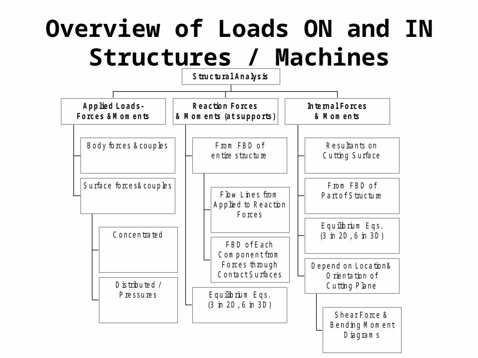
Overview of Loads ON and IN Structures / Machines
B o d y fo rces & cou p les
C o nce n tra ted
D is tribu te d /P re ssu res
S u rface fo rce s& cou p les
Applied Loads-Forces &M om ents
F lo w L in e s fromA p p lie d to R e ac tion
F o rces
F B D o f E a chC o m p o ne n t fromF o rces th ro u gh
C o nta c t S u rfa ces
F ro m FB D o fe n tire s truc tu re
E q u ilib riu m E q s.(3 in 2D , 6 in 3 D )
Reaction Forces& M om ents (at supports)
R e su lta n ts onC u tting S urfa ce
F ro m FB D o fP a rt o f S truc tu re
E q u ilib riu m E q s.(3 in 2D , 6 in 3 D )
S h e ar F orce &B e n d in g M o m e nt
D ia g ra m s
D e pe n d o n L oca tio n&O rie n ta tion o fC u ttin g P la ne
Internal Forces& M om ents
Structural Analysis
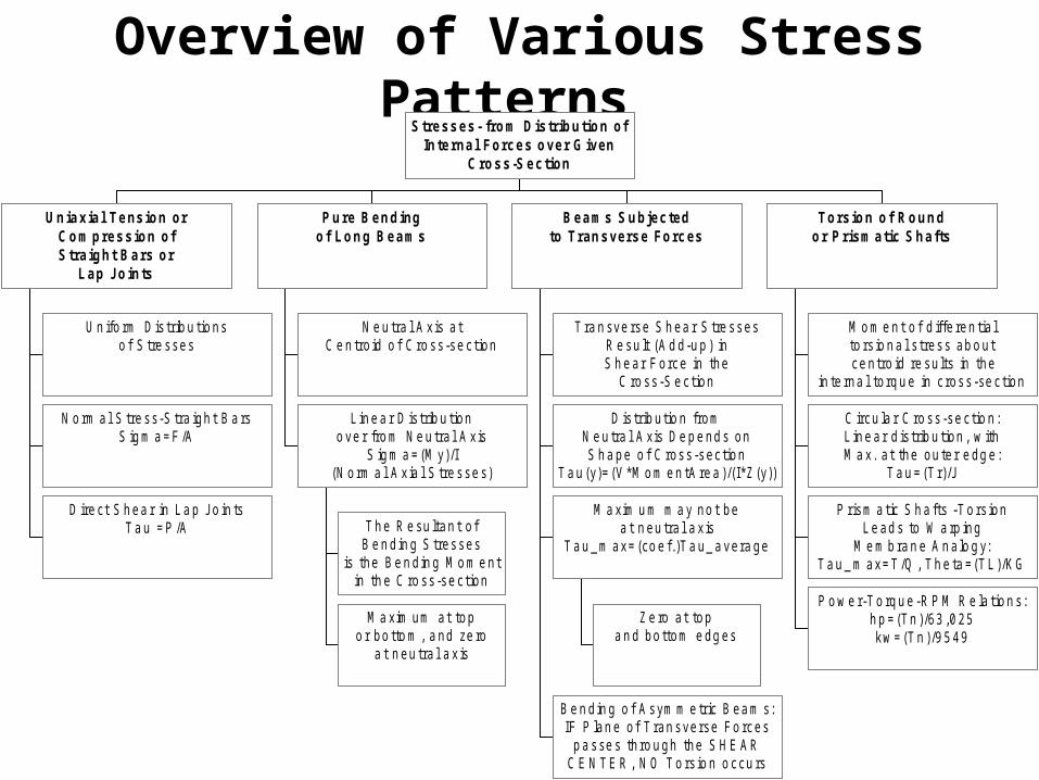
Overview of Various Stress Patterns
U n ifo rm D is trib u tio nso f S tre sses
N o rm al S tre ss-S tra igh t B a rsS ig m a = F /A
D ire ct S h ea r in L a p Jo in tsT a u = P /A
Uniaxial Tension orCom pression ofStraight Bars or
Lap Joints
N e u tra l A x is a tC e n tro id o f C ro ss -se c tion
T h e R e su ltan t o fB e n d in g S tresses
is the B e n d in g M o m e ntin th e C ro ss -se c tion
M a xim um a t topo r bo tto m , a nd ze ro
a t n eu tra l a x is
L in e a r D is trib u tiono ve r fro m N e u tra l A x is
S ig m a = (M y)/I(N o rm a l A x ia l S tre sse s)
Pure Bendingof Long Beams
T ra n sve rse S h ea r S tre ssesR e su lt (A d d-u p ) inS h e ar F orce in the
C ro ss -S e c tion
D is trib u tio n fromN e u tra l A xis D e p e nd s onS h a pe o f C ross -sec tion
T a u (y)= (V *M o m e n tA re a )/(I*Z (y))
Z e ro a t topa n d bo ttom e dg es
M a xim u m m a y no t bea t n eu tra l a x is
T a u _m ax= (co e f.)T a u_ a vera ge
B e n d in g o f A sym m e tric B ea m s:IF P lan e o f T ran sverse Fo rces
p a sse s th ro u gh the S H E A RC E N T E R , N O T o rs io n o ccu rs
Beams Subjectedto Transverse Forces
M o m e n t o f d iffe ren tia lto rs io n a l s tress ab o ut ce n tro id re su lts in the
in te rna l to rq u e in c ross -se c tion
C ircu la r C ro ss -se c tio n :L in e ar d is trib u tion , w ithM a x. a t the ou te r e dg e :
T a u = (T r)/J
P rism a tic S h a fts -T o rs ionL e ad s to W a rp ing
M e m b ra n e A n a lo g y:T a u _ m ax= T /Q , T h e ta =(T L )/K G
P o w e r-T o rq u e -R P M R e la tio n s:h p = (Tn )/63 ,0 25kw = (T n )/9 5 49
Torsion of Roundor Prism atic Shafts
Stresses- from Distribution ofInternal Forces over G iven
Cross-Section

Solution of Example Problem 4.3
• Step 1 –Construct shear&moment diagrams
• Step 2 –Find dmin=0.90in to resist allowable=35,000psi at section where Mmax=2500in-lb
• Step 3 –Find dmin=0.56in to resist allowable=20,200psi for maximum direct average shear stress
• Step 4 –Find dmin=0.65in to resist allowable=20,000psi for maximum transverse shear stress


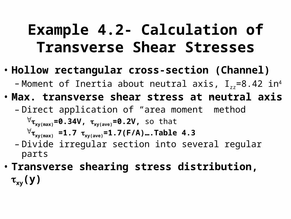
Example 4.2- Calculation of Transverse Shear Stresses
• Hollow rectangular cross-section (Channel)– Moment of Inertia about neutral axis, Izz=8.42 in4
• Max. transverse shear stress at neutral axis– Direct application of “area moment” method
xy(max)=0.34V, xy(ave)=0.2V, so that xy(max) =1.7 xy(ave)=1.7(F/A)….Table 4.3
– Divide irregular section into several regular parts
• Transverse shearing stress distribution, xy(y)


Summary of Solutions to Textbook Problems – Problem 4.10
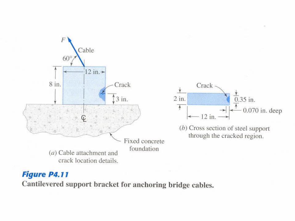
• Module support D6AC steel beam with two small hole and cracks– Ignore for now stress concentrations&fracture mechanics– Beam subjected to four-point bending
• Uniform bending moment at mid-span, M=PL/3 =281.25 kN-m• No transverse shear stress in central span, V =0
• Check for possible failure by yielding– Max. bending stress at:
• The tip of bottom crack, yct =10.3cm, x(ct)=(M*yct)/Izz=556 MPa• At the outer fibers: x(max)=(281.25x10³)(12.5x10⁻²)/5.21x10-5=675 Mpa
– From Table 2.1, Syp=1570MPa, so that the “safety factor” is equal to 1570/675=2.3 NO yielding

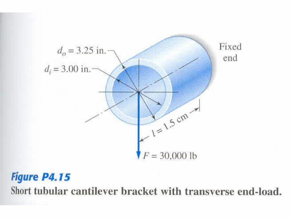
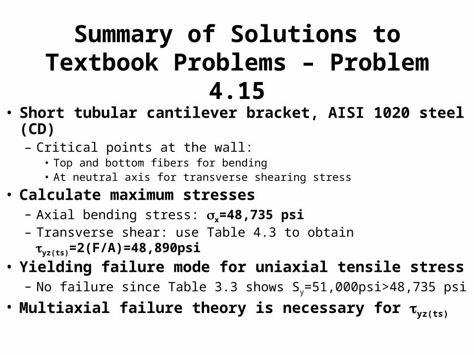
Summary of Solutions to Textbook Problems – Problem 4.15
• Short tubular cantilever bracket, AISI 1020 steel (CD)– Critical points at the wall:
• Top and bottom fibers for bending• At neutral axis for transverse shearing stress
• Calculate maximum stresses– Axial bending stress: x=48,735 psi– Transverse shear: use Table 4.3 to obtain yz(ts)=2(F/A)=48,890psi
• Yielding failure mode for uniaxial tensile stress– No failure since Table 3.3 shows Sy=51,000psi>48,735 psi
• Multiaxial failure theory is necessary for yz(ts)

Example 4.5- Calculation of Stresses in Channel-Section Cantilever Beam
• Determine maximum bending stress z(max)=48000(2.0)/4.74 =20,250 psi, Ixx=4.74in4
• Max. transverse shear at neutral axis– Area moment methods yields: zy(max)= 7720 psi
• Flow of torsional shearing stresses– Locate SHEAR CENTER by using Table 4.5: e=0.56 in– Find torsional moment since the plane of “P” is located at a
distance a=1.26 in. from the shear center: T=Pa =10,080 in-lb– Find horizontal shear forces that form resisting couple, T = Rd– Maximum torsional shearing stresses in the flanges:
zx(max)= R/Af= 2739/((1.72)(0.32)) = 4976 psi • Could be eliminated by translating the plane of “P” by 1.26in to the left


