overview of feko for efficiently solving emc problems with ... · pdf fileoverview of feko for...
TRANSCRIPT

Overview of FEKO for Efficiently Solving EMC Problems with Numerical Simulations
Dr. Markus Schick, Director Electromagnetic Solutions – EMEA
3rd September 2015
Introduction and FEKO Technology
Copyright © 2014 Altair Engineering, Inc. Proprietary and Confidential. All rights reserved.
3EMC Türkiye 2015, Istanbul, 3rd September 2015
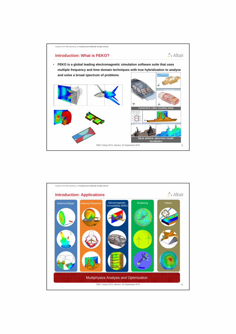
Introduction: What is FEKO?
• FEKO is a global leading electromagnetic simulation software suite that uses
multiple frequency and time domain techniques with true hybridization to analyse
and solve a broad spectrum of problems
Copyright © 2014 Altair Engineering, Inc. Proprietary and Confidential. All rights reserved.
4EMC Türkiye 2015, Istanbul, 3rd September 2015
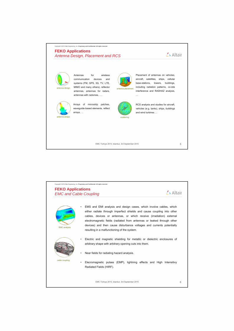
Introduction: Applications
Electromagnetic Compatibility (EMC)
Multiphysics Analysis and Optimization
Antenna Design Others ScatteringAntenna Placement
Copyright © 2014 Altair Engineering, Inc. Proprietary and Confidential. All rights reserved.
5EMC Türkiye 2015, Istanbul, 3rd September 2015
FEKO Applications Antenna Design, Placement and RCS
scattering
antenna design
antenna arrays
antenna placement
Antennas for wireless
communication devices and
systems (FM, GPS, 3G, TV, LTE,
MIMO and many others), reflector
antennas, antennas for radars,
antennas with radomes, ….
Arrays of microstrip patches,
waveguide-based elements, reflect
arrays, …
Placement of antennas on vehicles,
aircraft, satellites, ships, cellular
base-stations, towers, buildings,
including radiation patterns, co-site
interference and RADHAZ analysis,
…
RCS analysis and studies for aircraft,
vehicles (e.g. tanks), ships, buildings
and wind turbines …
Copyright © 2014 Altair Engineering, Inc. Proprietary and Confidential. All rights reserved.
6EMC Türkiye 2015, Istanbul, 3rd September 2015
EMC analysis
cable coupling
FEKO Applications EMC and Cable Coupling
• EMS and EMI analysis and design cases, which involve cables, which
either radiate through imperfect shields and cause coupling into other
cables, devices or antennas, or which receive (irradiation) external
electromagnetic fields (radiated from antennas or leaked through other
devices) and then cause disturbance voltages and currents potentially
resulting in a malfunctioning of the system.
• Electric and magnetic shielding for metallic or dielectric enclosures of
arbitrary shape with arbitrary opening cuts into them.
• Near fields for radiating hazard analysis.
• Elecromagnetic pulses (EMP), lightning effects and High Intensitivy
Radiated Fields (HIRF).

Copyright © 2014 Altair Engineering, Inc. Proprietary and Confidential. All rights reserved.
7EMC Türkiye 2015, Istanbul, 3rd September 2015
Introduction: Main industries
Aerospace
Automotive
Defense
Communications Consumer Electronics
Energy
Healthcare
Copyright © 2014 Altair Engineering, Inc. Proprietary and Confidential. All rights reserved.
8EMC Türkiye 2015, Istanbul, 3rd September 2015
Solvers in FEKO – Simulation Map
EL
EC
TR
ICA
L S
IZE
COMPLEXITY OF MATERIALS
FDTD
FEM
MLFMM
MoM
UTD
PO/RL-GO
Full-wave
Methods
(physicallyrigorous solution)
Asymptotic
Methods
(high-frequencyapproximation)
Hybridization to solve large and
complex problems
General study Cycle
Copyright © 2014 Altair Engineering, Inc. Proprietary and Confidential. All rights reserved.
10EMC Türkiye 2015, Istanbul, 3rd September 2015
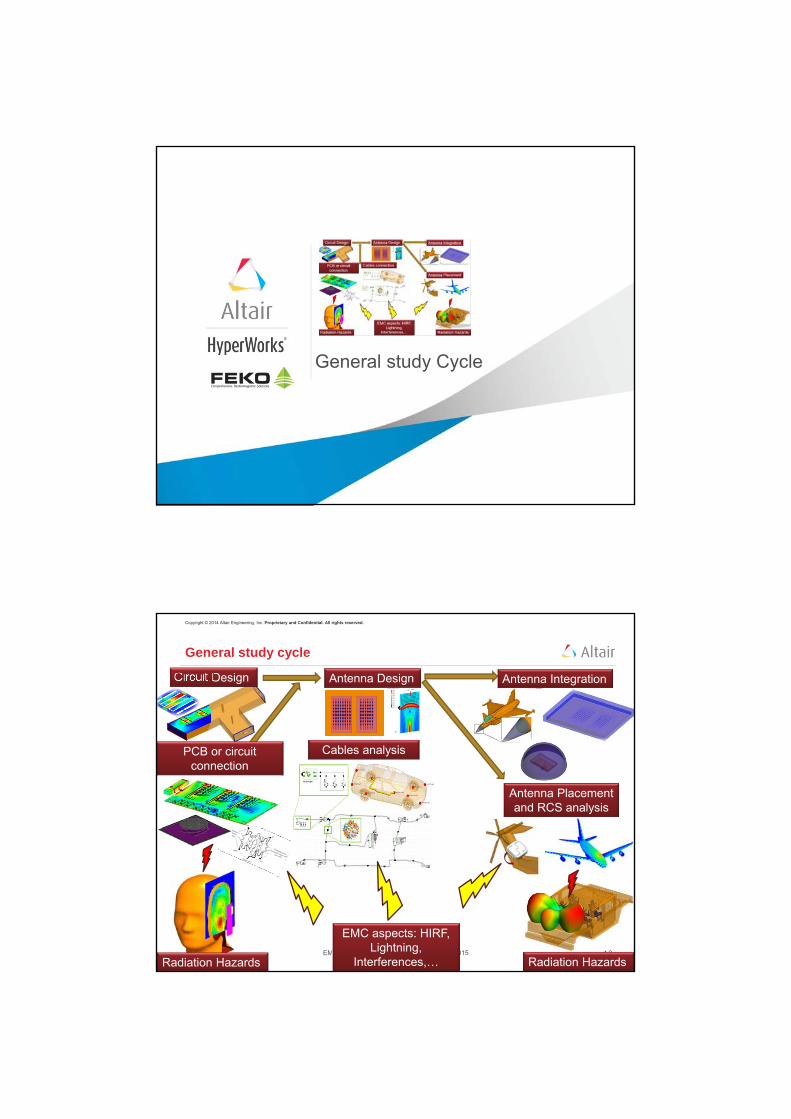
General study cycle
Circuit Design Antenna Design
Cables analysisPCB or circuit connection
Antenna Integration
Antenna Placement and RCS analysis
EMC aspects: HIRF, Lightning,
Interferences,…Radiation Hazards Radiation Hazards

Solution Scaling with Frequency
Copyright © 2014 Altair Engineering, Inc. Proprietary and Confidential. All rights reserved.
12EMC Türkiye 2015, Istanbul, 3rd September 2015
Solution Scaling: SAAB JAS-39 Gripen
14,6 m
8,23 m
3,37 m
Aircraft model used for the benchmark
• Doubling the solution frequency,
requires that the triangle mesh size is
halved
• This increases the number of mesh
elements, resulting in an increase in
the computational requirements
• This benchmark illustrates how
computational resources scale with
frequency, comparing requirements
for MLFMM and PO methods
Copyright © 2014 Altair Engineering, Inc. Proprietary and Confidential. All rights reserved.
13EMC Türkiye 2015, Istanbul, 3rd September 2015
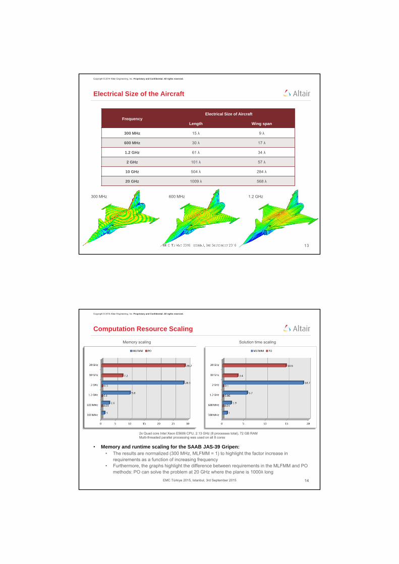
Electrical Size of the Aircraft
Frequency Electrical Size of Aircraft
Length Wing span
300 MHz 15 λ 9 λ
600 MHz 30 λ 17 λ
1.2 GHz 61 λ 34 λ
2 GHz 101 λ 57 λ
10 GHz 504 λ 284 λ
20 GHz 1009 λ 568 λ
300 MHz 600 MHz 1.2 GHz
Copyright © 2014 Altair Engineering, Inc. Proprietary and Confidential. All rights reserved.
14EMC Türkiye 2015, Istanbul, 3rd September 2015
Computation Resource Scaling
• Memory and runtime scaling for the SAAB JAS-39 Gripen:• The results are normalized (300 MHz, MLFMM = 1) to highlight the factor increase in
requirements as a function of increasing frequency• Furthermore, the graphs highlight the difference between requirements in the MLFMM and PO
methods: PO can solve the problem at 20 GHz where the plane is 1000λ long
Solution time scalingMemory scaling
2x Quad core Intel Xeon E5606 CPU, 2.13 GHz (8 processes total), 72 GB RAMMulti-threaded parallel processing was used on all 8 cores

Copyright © 2014 Altair Engineering, Inc. Proprietary and Confidential. All rights reserved.
15EMC Türkiye 2015, Istanbul, 3rd September 2015
Comparison of Results: MLFMM and PO
1.2 GHz 2.0 GHz
Aerospace

Copyright © 2014 Altair Engineering, Inc. Proprietary and Confidential. All rights reserved.
17EMC Türkiye 2015, Istanbul, 3rd September 2015
Simulating Composite Material Airframes
• F5 aircraft with carbon fibre construction• Fibre:
• Conductivity = 4x10⁴ S/m• Relative permittivity = 3.4
• Epoxy: (orthogonal to fibre)
• Conductivity = 50 S/m• Relative permittivity = 3.4
• Compute:• Monostatic RCS
• Surface current distribution
• Excitation:• Linearly polarised
plane wave
Metallic
Carbon fibrealignment
Metallic
Incident wave polarisation
Copyright © 2014 Altair Engineering, Inc. Proprietary and Confidential. All rights reserved.
18EMC Türkiye 2015, Istanbul, 3rd September 2015
Simulating Composite Material Airframes
Elevation RCS at 50 MHz Surface current distribution
Azimuth RCS at 50 MHz
Carbon fibre Metallic
Surface current distribution
Carbon fibre Metallic

EMCLightning Incident on an Aircraft
Copyright © 2014 Altair Engineering, Inc. Proprietary and Confidential. All rights reserved.
20EMC Türkiye 2015, Istanbul, 3rd September 2015
Why FEKO for lightning?
• Frequency-domain analysis• Time-domain codes need too many time steps
due to the low frequency components of the
lightning spectrum
• Exceptionally low noise floor• Inherent stability of MoM formulation
• Ability to simulate reliably down to a few Hz
• Efficient analysis of cable bundles
• Schematic capability• Add sources, components, terminations
and probes
• Time-analysis capability in POSTFEKO

Copyright © 2014 Altair Engineering, Inc. Proprietary and Confidential. All rights reserved.
21EMC Türkiye 2015, Istanbul, 3rd September 2015
Cables in aircraft
Initially cables are just modelled as conductors easy to reproduce in measurement
Copyright © 2014 Altair Engineering, Inc. Proprietary and Confidential. All rights reserved.
22EMC Türkiye 2015, Istanbul, 3rd September 2015
Currents with and without shielding
Important to know how much shielding is enough.
Don’t want to add too much weight and don’t want to lose flexibility.
Up to 1400 mA for unshielded cables
Up to 21 mA for shielded cables
Lightning‐induced currents observed at the shorted ends of the three unshielded cables
Helicopter Study
Copyright © 2014 Altair Engineering, Inc. Proprietary and Confidential. All rights reserved.
24EMC Türkiye 2015, Istanbul, 3rd September 2015
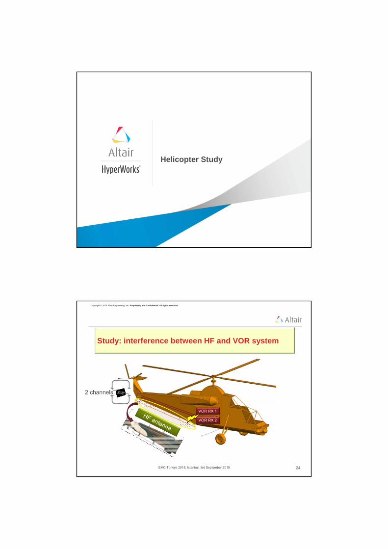
Study: interference between HF and VOR system
VOR RX 1
VOR RX 2
2 channels

Copyright © 2014 Altair Engineering, Inc. Proprietary and Confidential. All rights reserved.
25EMC Türkiye 2015, Istanbul, 3rd September 2015
VOR antenna
VOR RX 1
VOR RX 2
Interference betweenHF and VOR system
Interferences on the VOR system when the HF
antenna is used
Study: interference between HF and VOR system
Copyright © 2014 Altair Engineering, Inc. Proprietary and Confidential. All rights reserved.
26EMC Türkiye 2015, Istanbul, 3rd September 2015
2 Coaxial channelsVOR 1 & VOR 2
VOR 1
VOR 2
VOR RX 1
VOR RX 2
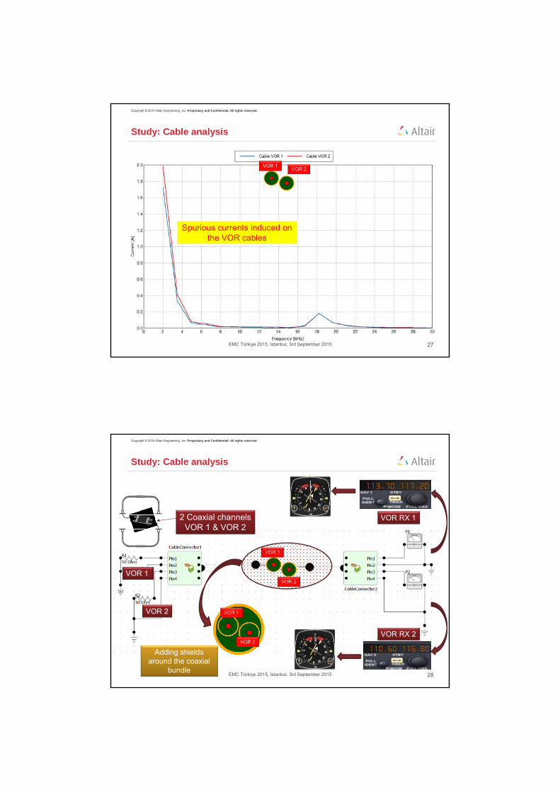
Study: Cable analysis
VOR 1
VOR 2
HF antenna
Copyright © 2014 Altair Engineering, Inc. Proprietary and Confidential. All rights reserved.
27EMC Türkiye 2015, Istanbul, 3rd September 2015
Spurious currents induced on the VOR cables
Study: Cable analysis
VOR 1VOR 2
Copyright © 2014 Altair Engineering, Inc. Proprietary and Confidential. All rights reserved.
28EMC Türkiye 2015, Istanbul, 3rd September 2015
2 Coaxial channelsVOR 1 & VOR 2
VOR 1
VOR 2
VOR RX 1
VOR RX 2
VOR 1
VOR 2
VOR 1
VOR 2
Adding shieldsaround the coaxial
bundle
Study: Cable analysis

Copyright © 2014 Altair Engineering, Inc. Proprietary and Confidential. All rights reserved.
29EMC Türkiye 2015, Istanbul, 3rd September 2015
Study: Cable analysis
Spurious currents levelattenuated
VOR 1VOR 1
Copyright © 2014 Altair Engineering, Inc. Proprietary and Confidential. All rights reserved.
30EMC Türkiye 2015, Istanbul, 3rd September 2015
Study: Cable analysis
Spurious currents levelattenuated
VOR 2VOR 2
Copyright © 2014 Altair Engineering, Inc. Proprietary and Confidential. All rights reserved.
31EMC Türkiye 2015, Istanbul, 3rd September 2015
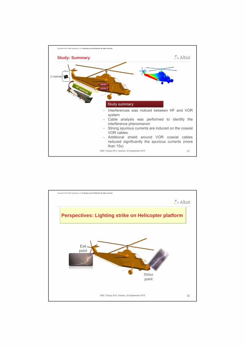
- Interferences was noticed between HF and VORsystem
- Cable analysis was performed to identify theinterference phenomenon
- Strong spurious currents are induced on the coaxialVOR cables.
- Additional shield around VOR coaxial cablesreduced significantly the spurious currents (morethan 15x)
Study summary:
Study: Summary
Copyright © 2014 Altair Engineering, Inc. Proprietary and Confidential. All rights reserved.
32EMC Türkiye 2015, Istanbul, 3rd September 2015
Perspectives: Lighting strike on Helicopter platform
Strikepoint
Exitpoint
Copyright © 2014 Altair Engineering, Inc. Proprietary and Confidential. All rights reserved.
33EMC Türkiye 2015, Istanbul, 3rd September 2015
Perspectives: Lighting strike on Helicopter platform
Strikepoint
Exitpoint
• Lightning strikes aircraft
• Investigate:– Antenna coupling
– Coupling to cables in aircraft
• Impressed current sources for strike and exit points
• Broad-band characterisation of frequency response of platform
– 1 kHz to 1 MHz in current example
– Double exponential pulse form
– Fast computation using AFS technology in FEKO
– Surface meshing efficiency using MoM / MLFMM
Copyright © 2014 Altair Engineering, Inc. Proprietary and Confidential. All rights reserved.
34EMC Türkiye 2015, Istanbul, 3rd September 2015
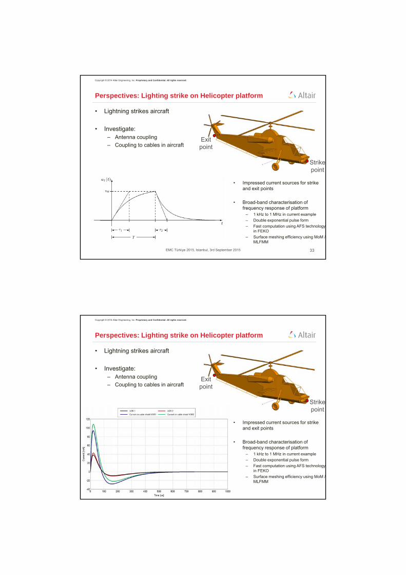
Perspectives: Lighting strike on Helicopter platform
Strikepoint
Exitpoint
• Lightning strikes aircraft
• Investigate:– Antenna coupling
– Coupling to cables in aircraft
• Impressed current sources for strike and exit points
• Broad-band characterisation of frequency response of platform
– 1 kHz to 1 MHz in current example
– Double exponential pulse form
– Fast computation using AFS technology in FEKO
– Surface meshing efficiency using MoM / MLFMM
Copyright © 2014 Altair Engineering, Inc. Proprietary and Confidential. All rights reserved.
35EMC Türkiye 2015, Istanbul, 3rd September 2015
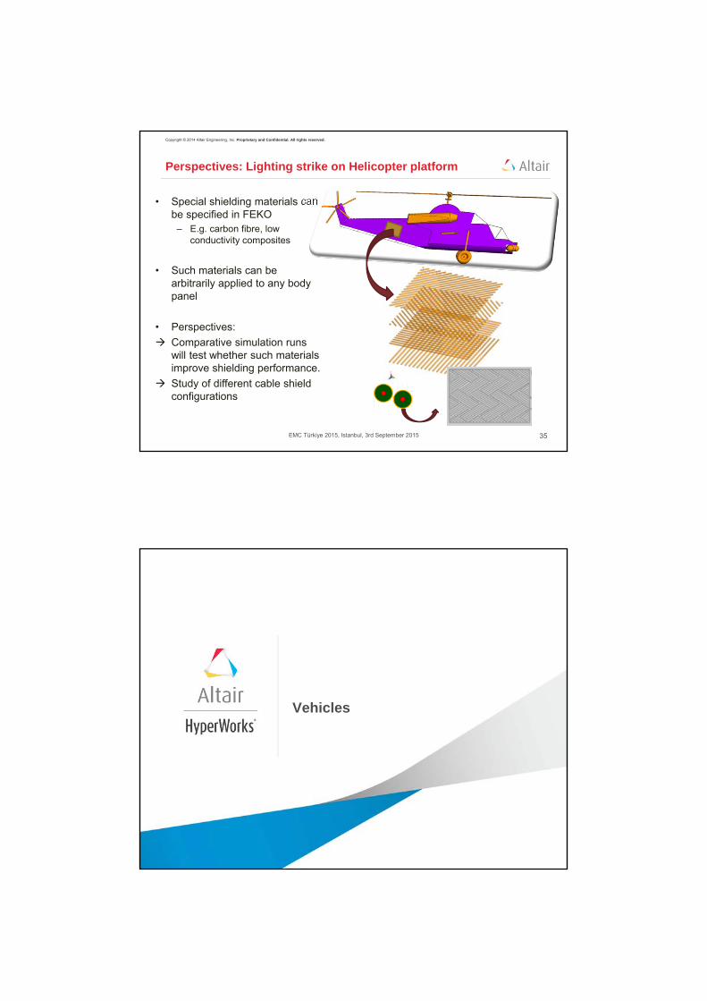
• Special shielding materials can be specified in FEKO
– E.g. carbon fibre, low conductivity composites
• Such materials can be arbitrarily applied to any body panel
• Perspectives:
Comparative simulation runs will test whether such materials improve shielding performance.
Study of different cable shield configurations
Perspectives: Lighting strike on Helicopter platform
Vehicles

Copyright © 2014 Altair Engineering, Inc. Proprietary and Confidential. All rights reserved.
37EMC Türkiye 2015, Istanbul, 3rd September 2015
Antenna Placement on Vehicles
• Evaluate communication blind spots
for vehicle antennas.
• Radiation hazard studies for
personnel next to or inside vehicle.
• Antenna coupling
Copyright © 2014 Altair Engineering, Inc. Proprietary and Confidential. All rights reserved.
38EMC Türkiye 2015, Istanbul, 3rd September 2015
Radiation Hazards of Multiple Transmitters (1)
• FEKO example (3 x monopole mounted on vehicle):• Compute radiation levels for each transmitter
• POSTFEKO Lua scripting:• Compute percentage contributions for each monopole
• Sum percentage contributions
• Render isosurfaces of maximum exposure boundaries
• Render field planes where colouring represents exposure levels
100 MHz 150 MHz 300 MHz

Copyright © 2014 Altair Engineering, Inc. Proprietary and Confidential. All rights reserved.
39EMC Türkiye 2015, Istanbul, 3rd September 2015
Radiation Hazards of Multiple Transmitters (2)
• Combined radiation hazard: 3 transmitters simultaneously transmitting
Percentage exposure levels (red = 100%)
Combined maximum exposure isosurfaces
Copyright © 2014 Altair Engineering, Inc. Proprietary and Confidential. All rights reserved.
40EMC Türkiye 2015, Istanbul, 3rd September 2015
ICNIRP Radiation Hazard Zones
• ICNIRP radiation hazard zones for TETRA vehicle mounted radio
• Yellow - Public safety zone
• Red - Occupational safety zone

Naval
Copyright © 2014 Altair Engineering, Inc. Proprietary and Confidential. All rights reserved.
42EMC Türkiye 2015, Istanbul, 3rd September 2015
Naval Antenna Placement
Effect of slanting
Effect of shielding-disc size
Antenna mounting options
Determine effect (patterns and isolation) of positional changes

PCB Level EMI
Copyright © 2014 Altair Engineering, Inc. Proprietary and Confidential. All rights reserved.
44EMC Türkiye 2015, Istanbul, 3rd September 2015
PCB Board Level EMI – Noise Coupling Analysis
Complex PCB geometries (ODB++ or Gerber formats) can be imported into
FEKO for board level analysis, including:
• Noise interference with antenna feeds and sensitive components
• Coupling between traces and layers
• Component placing and shielding analysis
Case study related to board level noise coupling
• The goal of the study was to investigate noise coupling
from various noise sources to the antenna feed port
• CMA was chosen due to the insight obtained
through modal analysis and modal currents
• A modification was purposed which successfully
reduced the coupling issue
multilayer PCB geometry for the study

Copyright © 2014 Altair Engineering, Inc. Proprietary and Confidential. All rights reserved.
45EMC Türkiye 2015, Istanbul, 3rd September 2015
basic more detailed with traces with antenna
mod
e #1
mod
e #3
mod
e #2
Incremental Detail Effect on Modal Current
The dominant modal behaviour is determined by the larger details on the board, and the antenna, the incremental detail
has a negligible effect on the modal current distribution
Copyright © 2014 Altair Engineering, Inc. Proprietary and Confidential. All rights reserved.
46EMC Türkiye 2015, Istanbul, 3rd September 2015
Reduced Coupling on Modified Design
Modal current, mode #3, 1.7 GHz - original geometry Modal current, mode #3, 1.7 GHz – modified geometry
S12_partial coupling mode #3 - original geometry S12_partial coupling mode #3 – modified geometry

Copyright © 2014 Altair Engineering, Inc. Proprietary and Confidential. All rights reserved.
47EMC Türkiye 2015, Istanbul, 3rd September 2015
S-parameter Coupling Verification
After problematic noise coupling was identified at 1.7 GHz, a design modification to the problematic area alleviates the interference.
The CMA investigation was verified with an S-parameter simulation: the coupling between the noise sources and the
antenna feed was calculated. The S-parameter data also verifies that the design modification will reduce the coupling.
Shielding Effectiveness
Copyright © 2014 Altair Engineering, Inc. Proprietary and Confidential. All rights reserved.
49EMC Türkiye 2015, Istanbul, 3rd September 2015
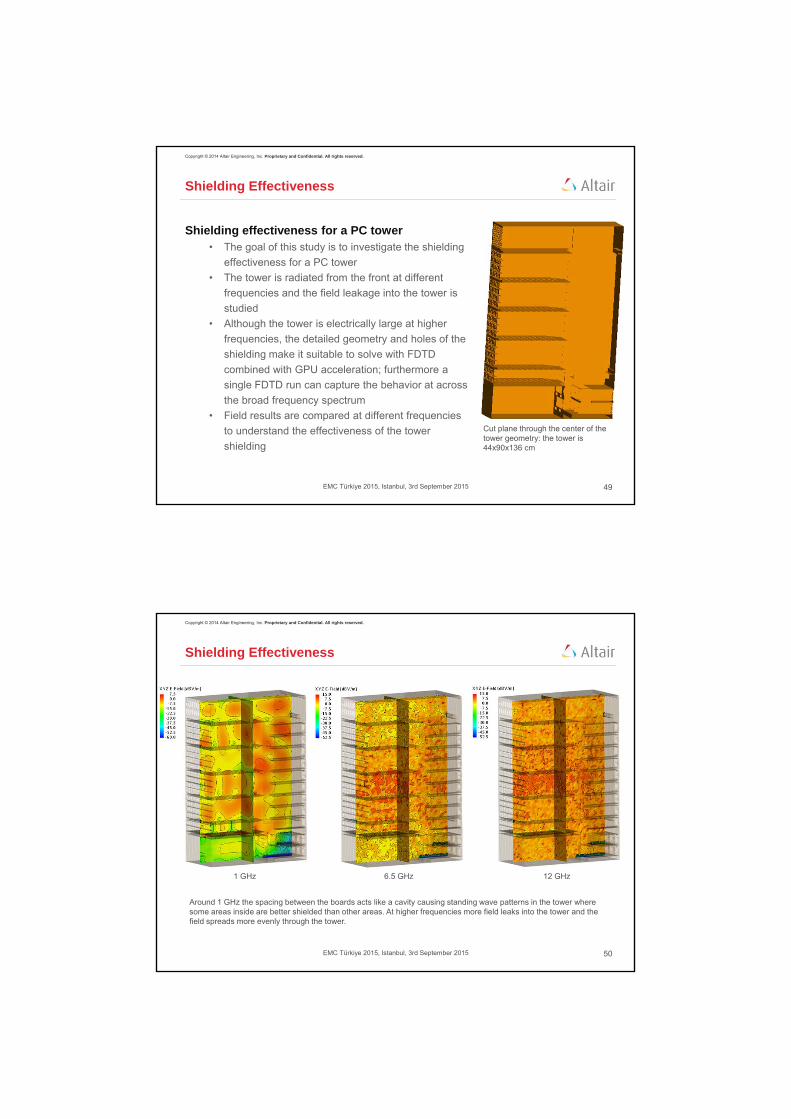
Shielding Effectiveness
Shielding effectiveness for a PC tower • The goal of this study is to investigate the shielding
effectiveness for a PC tower
• The tower is radiated from the front at different
frequencies and the field leakage into the tower is
studied
• Although the tower is electrically large at higher
frequencies, the detailed geometry and holes of the
shielding make it suitable to solve with FDTD
combined with GPU acceleration; furthermore a
single FDTD run can capture the behavior at across
the broad frequency spectrum
• Field results are compared at different frequencies
to understand the effectiveness of the tower
shielding
Cut plane through the center of the tower geometry: the tower is 44x90x136 cm
Copyright © 2014 Altair Engineering, Inc. Proprietary and Confidential. All rights reserved.
50EMC Türkiye 2015, Istanbul, 3rd September 2015
Shielding Effectiveness
Around 1 GHz the spacing between the boards acts like a cavity causing standing wave patterns in the tower where some areas inside are better shielded than other areas. At higher frequencies more field leaks into the tower and the field spreads more evenly through the tower.
1 GHz 6.5 GHz 12 GHz

Implant Antenna Design and Safety
Copyright © 2014 Altair Engineering, Inc. Proprietary and Confidential. All rights reserved.
52EMC Türkiye 2015, Istanbul, 3rd September 2015
Pacemaker Antenna Design
• Initial antenna performance simulated with homogeneous flat
phantom• the device is positioned 5mm below the surface and simulated with
MoM solver
• The performance is then verified using an anatomical model
(humanbodymodels.com) • the pacer is positioned accordingly in the phantom and simulated with
the FDTD solver
• The link budget shows that device telemetry will be possible up to
10m for -31dB antenna source power
[1] Design of an Implanted Compact Antenna for an Artificial Cardiac Pacemaker System, S. Lee, et al, IEICE Electronics Express,Vol. 8, No. 24, 2112-2117
low profile, high gain PIFA design for ISM band(400 MHz) [1]
generic pacemaker can and antenna housing volume ~ 40mm x 40mm x 8mm
total gain
surface currents

Copyright © 2014 Altair Engineering, Inc. Proprietary and Confidential. All rights reserved.
53EMC Türkiye 2015, Istanbul, 3rd September 2015
Antenna Design for Implanted Pacemaker
• Comparison of 2 different antenna designs
at 2 different operating frequencies
• Design #1: monopole design at 900 MHz
• Design #2: PIFA design at 400 MHz offers
superior gain performance than design #1
Copyright © 2014 Altair Engineering, Inc. Proprietary and Confidential. All rights reserved.
54EMC Türkiye 2015, Istanbul, 3rd September 2015
Pacemaker Antenna SAR Compliance
1g cube (IEEE Standards)
10g cube (ICNIRP Guidelines, CENELEC Procedures)
StandardBasic Restriction
[W/kg]
Factor below
Standard (%)
IEEE (North America)
2W/kg 1g cube 1.3%
ICNIRP (Europe) 2W/kg 10g cube 0.367%

Copyright © 2014 Altair Engineering, Inc. Proprietary and Confidential. All rights reserved.
55EMC Türkiye 2015, Istanbul, 3rd September 2015
Implant Safety for MRI - Transfer Function
• Implants need to be certified for safe usage
in MRI systems (SAR, temperature)
• Simulating the full simulation MRI + human +
implant is too complex when the implant lead
is consider, and must be solved in steps:• the implant and lead are simulated in a
homogeneous liquid with properties similar to
muscle tissue
• a transfer function for the lead is derived to
determine the response for a 1 V/m tangential
piecewise, excitation along the length of the lead
• with the knowledge of the transfer function and
incident field, the SAR and heating due to the RF
MRI field can be estimated at the lead tip
[1] Calculation of MRI-Induced Heating of an Implanted Medical Lead Wire With an Electric Field Transfer Function, Sung-Min Park, et al.
Copyright © 2014 Altair Engineering, Inc. Proprietary and Confidential. All rights reserved.
56EMC Türkiye 2015, Istanbul, 3rd September 2015
Generic Lead Transfer Functions – 64MHz
Wire geometries- bare wire (left) radius = 1.6mm
- uncapped wire (center) radius = 1.6mm, insulation radius = 2.5mm, 1cm of insulation removed on both ends
- capped wire (right) radius = 1.6mm, insulation radius = 2.5mm, 1cm of insulation removed on one end
bare wire uncapped wire capped wire
pu
bli
shed
res
ult
s [1
]F
EK
O s
imu
lati
on
res
ult
s

Copyright © 2014 Altair Engineering, Inc. Proprietary and Confidential. All rights reserved.
57EMC Türkiye 2015, Istanbul, 3rd September 2015
Implant Safety for MRI – Lead Geometry Simulation
• Despite the stepwise approach to estimate
implant safety, the simulations are still
complex when considering realistic
models • typically the leads used for the implants have
significant detail < 1mm
• multiple conductors run along the length of the
leads and are often twisted in helical
configurations to allow for flex in the lead
• FEKO’s MoM solver is well suited to this
problem: wires can be resolved with segments
reducing the computational requirements
• this can be considerably faster than e.g.
solving the problem with FDTD where many
time steps will be required due to the small
geometric detail
mrisurescan.com
cardiac pacing defibrillation and resynchronization
Copyright © 2014 Altair Engineering, Inc. Proprietary and Confidential. All rights reserved.
58EMC Türkiye 2015, Istanbul, 3rd September 2015
MRI Compatibility of a Hip Replacement
• The setup is for assessing
compliance of a hip implant in a 3T
volume coil:• at 124 MHz λmuscle ~ 30cm: could be
resonant effects• an ASTM (2009) rectangular phantom
is used for the setup• filled with muscle tissue simulating
liquid• the implant is positioned in the
phantom at a location where large field gradients occur
• field interactions, SAR distribution, and spatial peak averaged SAR values are calculated
• the temperature increase can also be calculated
ASTM phantomfilled with muscle simulating liquid
SAR distribution in the phantom showing hotspots at the tips: the peak SAR = 0.9 W/kg (0.5uT @ phantom center)
hip replacementin the phantom
length ~ 15cm λ/2 “resonance” can be seen in field distribution

Copyright © 2014 Altair Engineering, Inc. Proprietary and Confidential. All rights reserved.
59EMC Türkiye 2015, Istanbul, 3rd September 2015
Thermal Analysis in FEKO
• Lua script based implementation of the Pennes Bioheat equation, including
• SAR - metabolic processes adds heat
• Thermal conductivity - spreads heat
• Blood perfusion - removes heat (amount is temperature dependent)
• Air convection - removes heat
• Thermal radiation - removes heathttp://www.feko.info/support/lua-scripts/thermal-analysis
temperature increase near the implant tip
SAR distribution, 64 MHz temperature distribution after 10 min
40 W
20 W
Copyright © 2014 Altair Engineering, Inc. Proprietary and Confidential. All rights reserved.
60EMC Türkiye 2015, Istanbul, 3rd September 2015
Injectable Implant – 2.45 GHz
• In [1] a design is proposed at
the ISM band (2.45 GHz)• the diameter of the implant in
small enough that it can be
injected into the skin (without
surgery)
• Link budget requires antenna
gain GTX > -17dB for short range
communication < 20m
[1] Design of a Helical Folded Dipole Antenna for Biomedical Implants, Mizuno, et al.; EUCAP 2011
Ø 1mm 17.7mm
glass insulation dual folded dipole, ends terminated with a short
fat (2mm)
muscle (58mm)
-16.27 dBpeak gain
implant locationat skin muscle boundary
skin (2mm)
Copyright © 2014 Altair Engineering, Inc. Proprietary and Confidential. All rights reserved.
61EMC Türkiye 2015, Istanbul, 3rd September 2015
Thank you!
www.altairhyperworks.com/feko