overload relays - schuh · overload relays. manual reset or automatic reset can be selected with...
TRANSCRIPT
B1visit www.sprecherschuh.com/ecatalog for pricing and the most up to date informationSSNA2018
B
Over
load
Rel
ays
www.sprecherschuh.com/ecatalog - All pricing shown in US dollars - FY20
Overload Relays
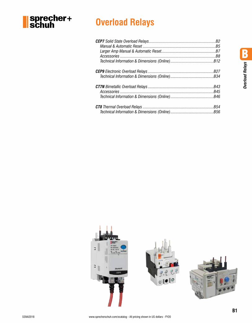
CEP7 Solid State Overload Relays .................................................................B2Manual & Automatic Reset .......................................................................B5Larger Amp Manual & Automatic Reset .....................................................B7Accessories .............................................................................................B8Technical Information & Dimensions (Online) ..........................................B12
CEP9 Electronic Overload Relays ................................................................B27Technical Information & Dimensions (Online) ..........................................B34
CT7N Bimetallic Overload Relays ................................................................B43Accessories ...........................................................................................B45Technical Information & Dimensions (Online) ..........................................B46
CT8 Thermal Overload Relays .....................................................................B54Technical Information & Dimensions (Online) ..........................................B56
B
CEP
7 Ov
erlo
ads
B2visit www.sprecherschuh.com/ecatalog for pricing and the most up to date information SSNA2018www.sprecherschuh.com/ecatalog - All pricing shown in US dollars - FY20
CEP7 Solid State Overload Relays
Advanced solid state motor protectionThe CEP7 solid state overload relay in-cludes advanced technology with several key features like:• Selectable trip class and field
installable modules• A wide (5:1) set current
adjustment range• A robust mechanical and
electrical mounting• Self-sealed latching mechanismThe basic concept of utilizing Applica-tion Specific Integrated Circuits (ASICs) results in an affordable solid state overload relay. This kind of versatility and accuracy is simply not possible with traditional bimetallic or eutectic alloy electromechanical overload relays.
Fewer units means greater application flexibilityThe CEP7 Soild State Overload Relay is available in three basic models:• CEP7-ED1 is a Class 10, manual reset
model available up to 45 amperes which covers the most common horsepower motors and your every day application. This model is eco-nomically priced to be competitive with adjustable bimetallic overload relays.
• CEP7-EE is a full featured selectable trip class (10, 15, 20 & 30) 3-phase application overload relay with provi-sion for field mountable modules to handle remote reset, jam protection, and other modules previously avail-able only in higher priced electronic overload relays.
Manual reset or automatic reset can be selected with dip switches on the CEP7-EE models.
• CEP7S-EE is a 1-phase application overload relay packing all features of the 3-phase CEP7-EE model.
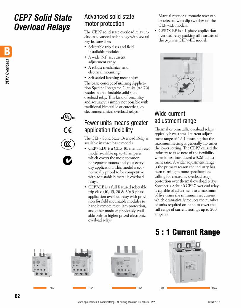
Wide current adjustment rangeThermal or bimetallic overload relays typically have a small current adjust-ment range of 1.5:1 meaning that the maximum setting is generally 1.5 times the lower setting. The CEP7 caused the industry to take note of the flexibility when it first introduced a 3.2:1 adjust-ment ratio. A wider adjustment range is the primary reason the industry has been turning to more specifications calling for electronic overload relay protection over thermal overload relays. Sprecher + Schuh’s CEP7 overload relay is capable of adjustment to a maximum of five times the minimum set current, which dramatically reduces the number of units required on-hand to cover the full range of current settings up to 200 amperes.
45A 120A 200A30A
5 : 1 Current Range
45A
B
CEP
7 Ov
erlo
ads
B3visit www.sprecherschuh.com/ecatalog for pricing and the most up to date informationSSNA2018 www.sprecherschuh.com/ecatalog - All pricing shown in US dollars - FY20
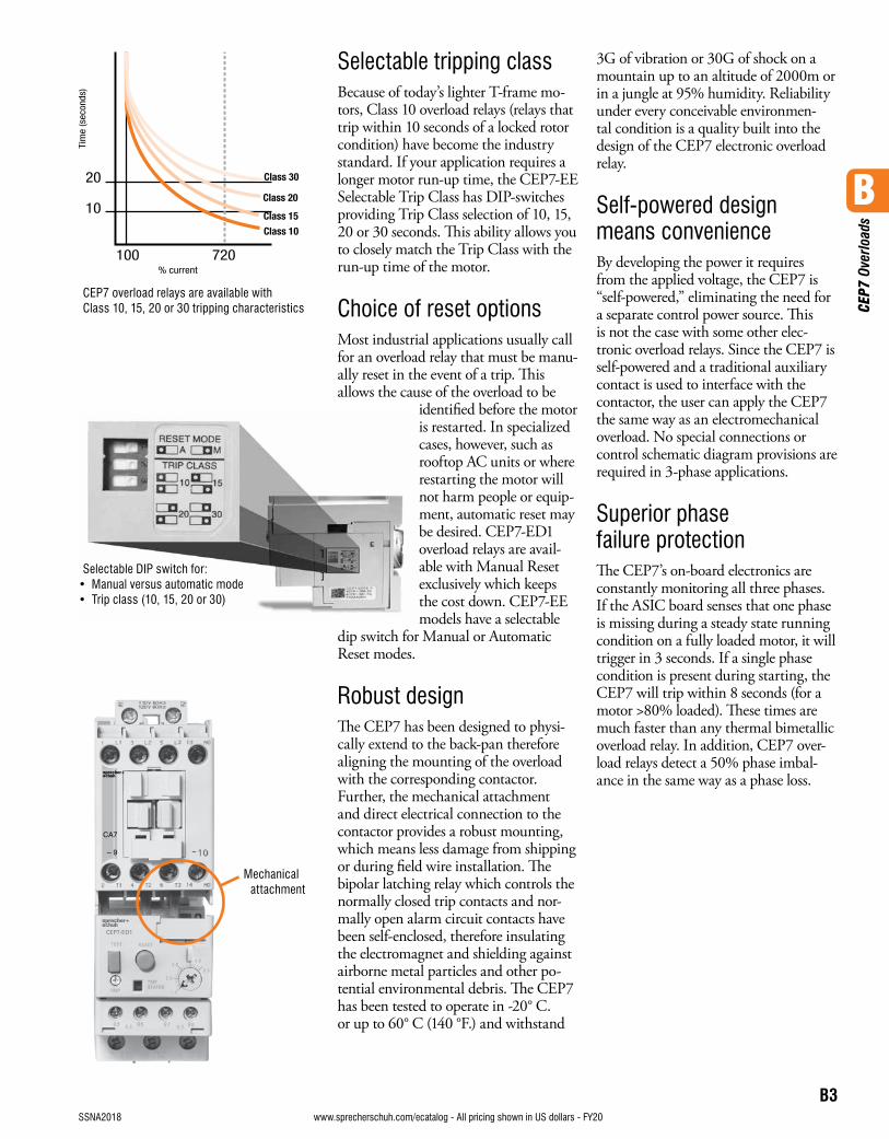
Selectable tripping classBecause of today’s lighter T-frame mo-tors, Class 10 overload relays (relays that trip within 10 seconds of a locked rotor condition) have become the industry standard. If your application requires a longer motor run-up time, the CEP7-EE Selectable Trip Class has DIP-switches providing Trip Class selection of 10, 15, 20 or 30 seconds. This ability allows you to closely match the Trip Class with the run-up time of the motor.
Choice of reset optionsMost industrial applications usually call for an overload relay that must be manu-ally reset in the event of a trip. This allows the cause of the overload to be
identified before the motor is restarted. In specialized cases, however, such as rooftop AC units or where restarting the motor will not harm people or equip-ment, automatic reset may be desired. CEP7-ED1 overload relays are avail-able with Manual Reset exclusively which keeps the cost down. CEP7-EE models have a selectable
dip switch for Manual or Automatic Reset modes.
Robust designThe CEP7 has been designed to physi-cally extend to the back-pan therefore aligning the mounting of the overload with the corresponding contactor. Further, the mechanical attachment and direct electrical connection to the contactor provides a robust mounting, which means less damage from shipping or during field wire installation. The bipolar latching relay which controls the normally closed trip contacts and nor-mally open alarm circuit contacts have been self-enclosed, therefore insulating the electromagnet and shielding against airborne metal particles and other po-tential environmental debris. The CEP7 has been tested to operate in -20° C. or up to 60° C (140 °F.) and withstand
3G of vibration or 30G of shock on a mountain up to an altitude of 2000m or in a jungle at 95% humidity. Reliability under every conceivable environmen-tal condition is a quality built into the design of the CEP7 electronic overload relay.
Self-powered design means convenienceBy developing the power it requires from the applied voltage, the CEP7 is “self-powered,” eliminating the need for a separate control power source. This is not the case with some other elec-tronic overload relays. Since the CEP7 is self-powered and a traditional auxiliary contact is used to interface with the contactor, the user can apply the CEP7 the same way as an electromechanical overload. No special connections or control schematic diagram provisions are required in 3-phase applications.
Superior phase failure protectionThe CEP7’s on-board electronics are constantly monitoring all three phases. If the ASIC board senses that one phase is missing during a steady state running condition on a fully loaded motor, it will trigger in 3 seconds. If a single phase condition is present during starting, the CEP7 will trip within 8 seconds (for a motor >80% loaded). These times are much faster than any thermal bimetallic overload relay. In addition, CEP7 over-load relays detect a 50% phase imbal-ance in the same way as a phase loss.
CEP7 overload relays are available with Class 10, 15, 20 or 30 tripping characteristics
Selectable DIP switch for:• Manual versus automatic mode• Trip class (10, 15, 20 or 30)
Mechanical attachment
B
CEP
7 Ov
erlo
ads
B4visit www.sprecherschuh.com/ecatalog for pricing and the most up to date information SSNA2018www.sprecherschuh.com/ecatalog - All pricing shown in US dollars - FY20
Additional Protection with Side Mount ModulesThe CEP7 offers a variety of field installable accessories for side mount on the left side. Side mount modules provide additional motor protection functionality traditionally found only on more expensive models. Modules include the following additional features.• Remote Reset provision for reset
after trip from a remote pilot device• Jam Protection/Remote Reset
provides adjustable Jam set points and trip delay plus remote reset
• Ground Fault Protection/Remote Reset combined with ground fault current transformers provide adjustable set points for ground fault trip protection of equipment plus remote reset
• Ground Fault/Jam Protection/Remote Reset combines all three features as described above
• PTC Thermistor Relay/Remote Reset manages thermistor sensor signals from the motor
• Network Communication Modules provide motor diagnostic information via Ethernet communication- Two discreet Inputs and one
discreet Output- Differentiate between various
motor protection algorithms- Overload and underload warning- Jam protection- Proactively alert maintenance
personnel just before or when a fault occurs
- Plus remote reset
Thermal CEP7-ED1CB… CEP7-EE_D CEP7-EE_E -ED1EB
6
5
4
3
2
1
0
Wat
ts
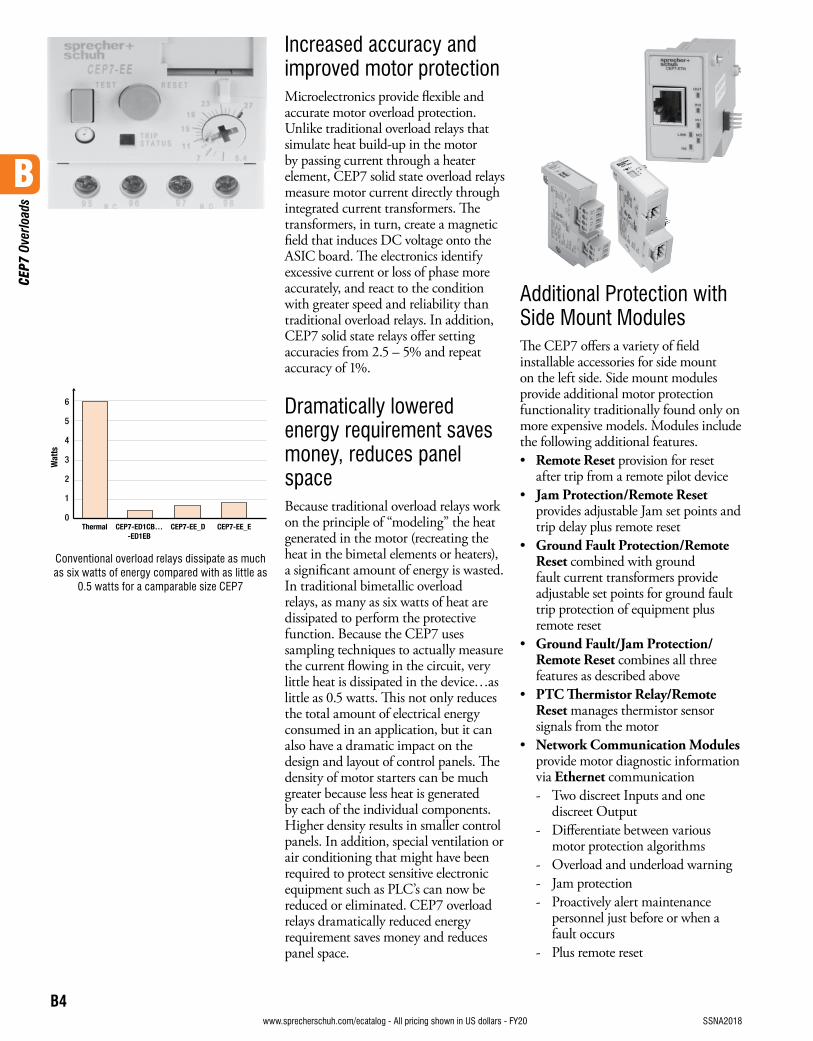
Conventional overload relays dissipate as much as six watts of energy compared with as little as
0.5 watts for a camparable size CEP7
Increased accuracy and improved motor protectionMicroelectronics provide flexible and accurate motor overload protection. Unlike traditional overload relays that simulate heat build-up in the motor by passing current through a heater element, CEP7 solid state overload relays measure motor current directly through integrated current transformers. The transformers, in turn, create a magnetic field that induces DC voltage onto the ASIC board. The electronics identify excessive current or loss of phase more accurately, and react to the condition with greater speed and reliability than traditional overload relays. In addition, CEP7 solid state relays offer setting accuracies from 2.5 – 5% and repeat accuracy of 1%.
Dramatically lowered energy requirement saves money, reduces panel spaceBecause traditional overload relays work on the principle of “modeling” the heat generated in the motor (recreating the heat in the bimetal elements or heaters), a significant amount of energy is wasted. In traditional bimetallic overload relays, as many as six watts of heat are dissipated to perform the protective function. Because the CEP7 uses sampling techniques to actually measure the current flowing in the circuit, very little heat is dissipated in the device…as little as 0.5 watts. This not only reduces the total amount of electrical energy consumed in an application, but it can also have a dramatic impact on the design and layout of control panels. The density of motor starters can be much greater because less heat is generated by each of the individual components. Higher density results in smaller control panels. In addition, special ventilation or air conditioning that might have been required to protect sensitive electronic equipment such as PLC’s can now be reduced or eliminated. CEP7 overload relays dramatically reduced energy requirement saves money and reduces panel space.
B
CEP
7 Ov
erlo
ads
B5visit www.sprecherschuh.com/ecatalog for pricing and the most up to date informationSSNA2018
Discount Schedule B3www.sprecherschuh.com/ecatalog - All pricing shown in US dollars - FY20
Overload RelayDirectly Mounts to Contactor… ➋
Adjustment Range (A)
Adjustable Trip Class 10, 15, 20 & 30
Catalog Number Price
Automatic or Manual Reset for 3Ø Applications ➊
CA7-9…CA7-23
CAN7-12, CAN7-16
0.1…0.5 CEP7-EEAB 83.30
0.2…1.0 CEP7-EEBB 83.30
1.0…5.0 CEP7-EECB 83.30
3.2… 16 CEP7-EEDB 83.30
5.4…27 CEP7-EEEB 83.30
CA7-30…CA7-55CAN7-37, CAN7-43
1.0…5.0 CEP7-EECD 133.00
3.2…16 CEP7-EEDD 133.00
5.4…27 CEP7-EEED 133.00
9…45 CEP7-EEFD 133.00
11…55 CEP7-EEQD 133.00
CA7-60…CA7-97CAN7-85
5.4…27 CEP7-EEEE 150.00
9…45 CEP7-EEFE 150.00
18…90 CEP7-EEGE 150.00
60…120 CEP7-EEVE 150.00
Automatic or Manual Reset for 1Ø Applications ➊
CA7-9…CA7-23
CAN7-12, CAN7-16
1.0…5.0 CEP7S-EEPB 83.30
3.2…16 CEP7S-EERB 83.30
5.4…27 CEP7S-EESB 83.30
CA7-30…CA7-43CAN7-37, CAN7-43 9…45 CEP7S-EETD 133.00
CA7-60…CA7-97CAN7-85 18…90 CEP7S-EEUE 150.00
Solid State Overload RelaysCEP7
Directly Mounted CEP7 Solid State Overload Relays, Manual Reset ➊➋➍
Overload RelayDirectly Mounts to Contactor… ➋
Adjustment Range (A)
Trip Class 10
Catalog Number Price
Manual Reset for 3Ø Applications ➊
CA7-9…CA7-23CAN7-12, CAN7-16
0.1…0.5 CEP7-ED1AB 73.70
0.2…1.0 CEP7-ED1BB 73.70
1.0…5.0 CEP7-ED1CB 73.70
3.2…16 CEP7-ED1DB 73.70
5.4…27 CEP7-ED1EB 73.70
CA7-30…CA7-55CAN7-37, CAN7-43
1.0…5.0 CEP7-ED1CD 114.00
3.2…16 CEP7-ED1DD 114.00
5.4…27 CEP7-ED1ED 114.00
9…45 CEP7-ED1FD 114.00
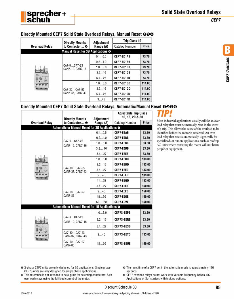
Directly Mounted CEP7 Solid State Overload Relays, Automatic/Manual Reset ➊➋➌➍
➊ 3-phase CEP7 units are only designed for 3Ø applications. Single phase CEP7S units are only designed for single phase applications.
➋ This reference is not intended to be a guide for selecting contactors. Size overload relays using the full load current of the motor.
➌ The reset time of a CEP7 set in the automatic mode is approximately 120 seconds.
➍ CEP7 overload relays do not work with Variable Frequency Drives, DC Applications or Softstarters with braking options.
Most industrial applications usually call for an over-load relay that must be manually reset in the event of a trip. This allows the cause of the overload to be identified before the motor is restarted. An over-load relay that resets automatically is generally for specialized, or remote applications, such as rooftop AC units where restarting the motor will not harm people or equipment.
TIP!
B
CEP
7 Ov
erlo
ads
B6visit www.sprecherschuh.com/ecatalog for pricing and the most up to date information SSNA2018
Discount Schedule B3www.sprecherschuh.com/ecatalog - All pricing shown in US dollars - FY20
Overload RelaySeparate Mount for use with… ➋
Adjustment Range (A)
Trip Class 10
Catalog Number Price
Manual Reset for 3Ø Applications ➊➍
Fig. 1
CA8-09…12CA7-9…CA7-23CAN7-12…CAN7-37
1.0…5.0 CEP7-ED1CP 73.70
3.2… 16 CEP7-ED1DP 73.70
5.4…27 CEP7-ED1EP 73.70
Overload RelaySeparate Mount for use with… ➋
Adjustment Range (A)
Adjustable Trip Class 10, 15, 20 & 30
Catalog Number Price
Automatic or Manual Reset for 3Ø Applications ➊➌➍
Fig. 1
CA8-09…12
CA7-9…CA7-23
CAN7-12…CAN7-37
1.0…5.0 CEP7-EECP 79.10
3.2… 16 CEP7-EEDP 79.10
5.4…27 CEP7-EEEP 79.10
Automatic or Manual Reset for 1Ø Applications ➊➌➍
Fig. 1
CA8-09…12
CA7-9…CA7-23
CAN7-12…CAN7-37
1.0…5.0 CEP7S-EEPP 79.10
3.2…16 CEP7S-EERP 79.10
5.4…27 CEP7S-EESP 79.10
Solid State Overload RelaysCEP7
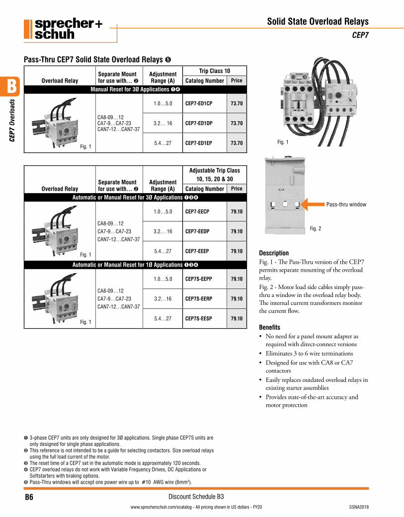
Pass-Thru CEP7 Solid State Overload Relays ➎
➊ 3-phase CEP7 units are only designed for 3Ø applications. Single phase CEP7S units are only designed for single phase applications.
➋ This reference is not intended to be a guide for selecting contactors. Size overload relays using the full load current of the motor.
➌ The reset time of a CEP7 set in the automatic mode is approximately 120 seconds.➍ CEP7 overload relays do not work with Variable Frequency Drives, DC Applications or
Softstarters with braking options.➎ Pass-Thru windows will accept one power wire up to #10 AWG wire (6mm2).
Description Fig. 1 - The Pass-Thru version of the CEP7 permits separate mounting of the overload relay. Fig. 2 - Motor load side cables simply pass-thru a window in the overload relay body. The internal current transformers monitor the current flow.
Benefits• No need for a panel mount adapter as
required with direct-connect versions• Eliminates 3 to 6 wire terminations• Designed for use with CA8 or CA7
contactors• Easily replaces outdated overload relays in
existing starter assemblies• Provides state-of-the-art accuracy and
motor protection
Pass-thru window
Fig. 2
Fig. 1
B
CEP
7 Ov
erlo
ads
B7visit www.sprecherschuh.com/ecatalog for pricing and the most up to date informationSSNA2018
Discount Schedule B3www.sprecherschuh.com/ecatalog - All pricing shown in US dollars - FY20
Solid State Overload Relays & AccessoriesCEP7
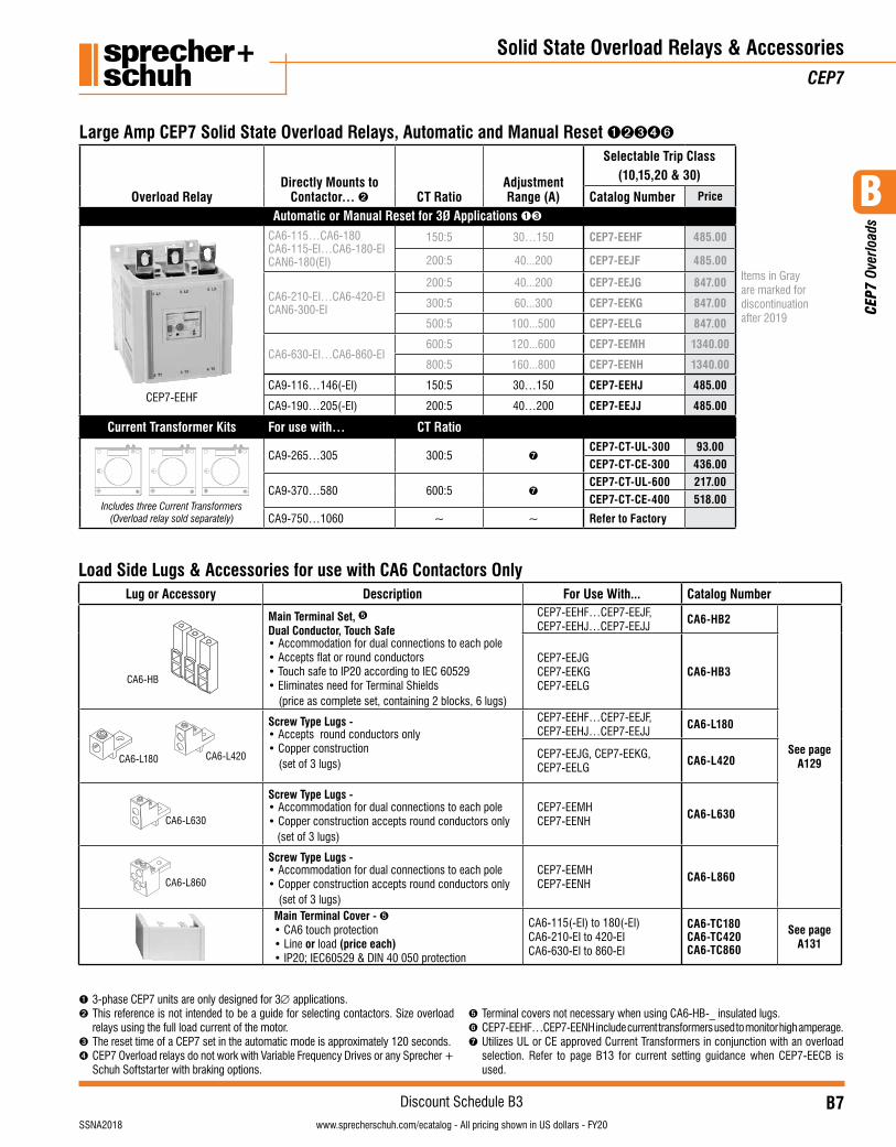
Large Amp CEP7 Solid State Overload Relays, Automatic and Manual Reset ➊➋➌➍➏
Overload RelayDirectly Mounts to
Contactor… ➋ CT RatioAdjustment Range (A)
Selectable Trip Class (10,15,20 & 30)
Items in Gray are marked for discontinuation after 2019
Catalog Number Price
Automatic or Manual Reset for 3Ø Applications ➊➌
CEP7-EEHF
CA6-115…CA6-180CA6-115-EI…CA6-180-EICAN6-180(EI)
150:5 30…150 CEP7-EEHF 485.00
200:5 40...200 CEP7-EEJF 485.00
CA6-210-EI…CA6-420-EICAN6-300-EI
200:5 40...200 CEP7-EEJG 847.00
300:5 60...300 CEP7-EEKG 847.00
500:5 100...500 CEP7-EELG 847.00
CA6-630-EI…CA6-860-EI600:5 120...600 CEP7-EEMH 1340.00
800:5 160...800 CEP7-EENH 1340.00
CA9-116…146(-EI) 150:5 30…150 CEP7-EEHJ 485.00
CA9-190…205(-EI) 200:5 40…200 CEP7-EEJJ 485.00
Current Transformer Kits For use with… CT Ratio
Includes three Current Transformers (Overload relay sold separately)
CA9-265…305 300:5 ➐CEP7-CT-UL-300 93.00CEP7-CT-CE-300 436.00
CA9-370…580 600:5 ➐CEP7-CT-UL-600 217.00CEP7-CT-CE-400 518.00
CA9-750…1060 ~ ~ Refer to Factory
➊ 3-phase CEP7 units are only designed for 3∅ applications.➋ This reference is not intended to be a guide for selecting contactors. Size overload
relays using the full load current of the motor.➌ The reset time of a CEP7 set in the automatic mode is approximately 120 seconds.➍ CEP7 Overload relays do not work with Variable Frequency Drives or any Sprecher +
Schuh Softstarter with braking options.
➎ Terminal covers not necessary when using CA6-HB-_ insulated lugs.➏ CEP7-EEHF…CEP7-EENH include current transformers used to monitor high amperage. ➐ Utilizes UL or CE approved Current Transformers in conjunction with an overload
selection. Refer to page B13 for current setting guidance when CEP7-EECB is used.
Load Side Lugs & Accessories for use with CA6 Contactors Only Lug or Accessory Description For Use With... Catalog Number
CA6-HB
Main Terminal Set, ➎Dual Conductor, Touch Safe• Accommodation for dual connections to each pole• Accepts flat or round conductors• Touch safe to IP20 according to IEC 60529• Eliminates need for Terminal Shields
(price as complete set, containing 2 blocks, 6 lugs)
CEP7-EEHF…CEP7-EEJF,CEP7-EEHJ…CEP7-EEJJ
CA6-HB2
See page A129
CEP7-EEJGCEP7-EEKGCEP7-EELG
CA6-HB3
CA6-L180 CA6-L420
Screw Type Lugs -• Accepts round conductors only• Copper construction
(set of 3 lugs)
CEP7-EEHF…CEP7-EEJF,CEP7-EEHJ…CEP7-EEJJ
CA6-L180
CEP7-EEJG, CEP7-EEKG, CEP7-EELG
CA6-L420
CA6-L630
Screw Type Lugs -• Accommodation for dual connections to each pole• Copper construction accepts round conductors only
(set of 3 lugs)
CEP7-EEMHCEP7-EENH
CA6-L630
CA6-L860
Screw Type Lugs -• Accommodation for dual connections to each pole• Copper construction accepts round conductors only
(set of 3 lugs)
CEP7-EEMHCEP7-EENH
CA6-L860
Main Terminal Cover - ➎• CA6 touch protection• Line or load (price each)• IP20; IEC60529 & DIN 40 050 protection
CA6-115(-EI) to 180(-EI) CA6-210-EI to 420-EI CA6-630-EI to 860-EI
CA6-TC180 CA6-TC420 CA6-TC860
See page A131
B
CEP
7 Ov
erlo
ads
B8visit www.sprecherschuh.com/ecatalog for pricing and the most up to date information SSNA2018
Discount Schedule B3www.sprecherschuh.com/ecatalog - All pricing shown in US dollars - FY20
Accessories – Field InstallableCEP7 Solid State Overload Relays
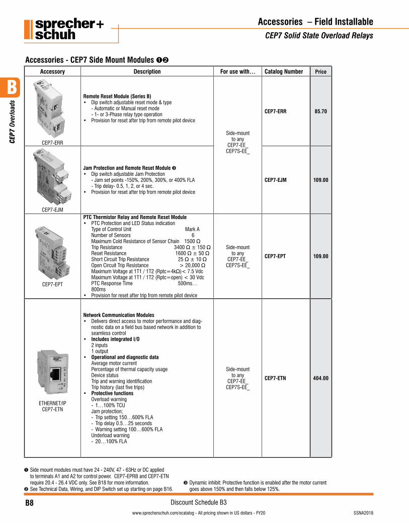
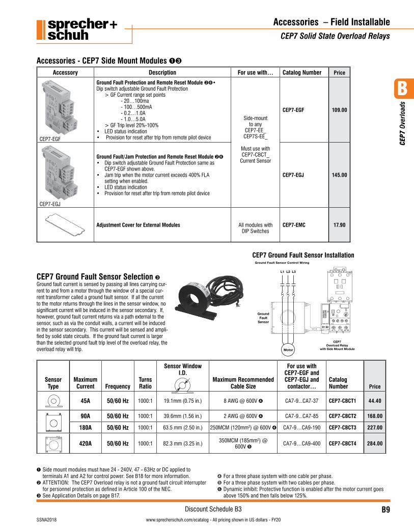
Accessories - CEP7 Side Mount Modules ➊➋
Accessory Description For use with… Catalog Number Price
CEP7-ERR
Remote Reset Module (Series B)• Dip switch adjustable reset mode & type - Automatic or Manual reset mode - 1- or 3-Phase relay type operation• Provision for reset after trip from remote pilot device
Side-mountto any
CEP7-EE_CEP7S-EE_
CEP7-ERR 85.70
CEP7-EJM
Jam Protection and Remote Reset Module ➌• Dip switch adjustable Jam Protection - Jam set points -150%, 200%, 300%, or 400% FLA - Trip delay- 0.5, 1, 2, or 4 sec.• Provision for reset after trip from remote pilot device
CEP7-EJM 109.00
CEP7-EPT
PTC Thermistor Relay and Remote Reset Module• PTC Protection and LED Status indication Type of Control Unit Mark A Number of Sensors 6 Maximum Cold Resistance of Sensor Chain 1500 Ω Trip Resistance 3400 Ω ± 150 Ω Reset Resistance 1600 Ω ± 50 Ω Short Circuit Trip Resistance 25 Ω ± 10 Ω Open Circuit Trip Resistance > 20,000 Ω Maximum Voltage at 1T1 / 1T2 (Rptc=4kΩ) < 7.5 Vdc Maximum Voltage at 1T1 / 1T2 (Rptc=open) < 30 Vdc PTC Response Time 500ms…
800ms• Provision for reset after trip from remote pilot device
Side-mountto any
CEP7-EE_CEP7S-EE_
CEP7-EPT 109.00
ETHERNET/IP CEP7-ETN
Network Communication Modules• Delivers direct access to motor performance and diag-
nostic data on a field bus based network in addition to seamless control
• Includes integrated I/O 2 inputs
1 output• Operational and diagnostic data
Average motor current Percentage of thermal capacity usage Device status Trip and warning identification Trip history (last five trips)
• Protective functions Overload warning - 1…100% TCU Jam protection; - Trip setting 150…600% FLA - Trip delay 0.5…25 seconds - Warning setting 100…600% FLA Underload warning - 20…100% FLA
Side-mountto any
CEP7-EE_CEP7S-EE_
CEP7-ETN 404.00
➊ Side mount modules must have 24 - 240V, 47 - 63Hz or DC applied to terminals A1 and A2 for control power. CEP7-EPRB and CEP7-ETN require 20.4 - 26.4 VDC only. See B18 for more information.
➋ See Technical Data, Wiring, and DIP Switch set up starting on page B16.➌ Dynamic inhibit: Protective function is enabled after the motor current
goes above 150% and then falls below 125%.
B
CEP
7 Ov
erlo
ads
B9visit www.sprecherschuh.com/ecatalog for pricing and the most up to date informationSSNA2018
Discount Schedule B3www.sprecherschuh.com/ecatalog - All pricing shown in US dollars - FY20
CEP7 Ground Fault Sensor Selection ➌Ground fault current is sensed by passing all lines carrying cur-rent to and from a motor through the window of a special cur-rent transformer called a ground fault sensor. If all the current to the motor returns through the lines in the sensor window, no significant current will be induced in the sensor secondary. If, however, ground fault current returns via a path external to the sensor, such as via the conduit walls, a current will be induced in the sensor secondary. This current will be sensed and ampli-fied by solid state circuits. If the ground fault current is larger than the selected ground fault trip level of the overload relay, the overload relay will trip.
Sensor Type
Maximum Current Frequency
Turns Ratio
Sensor Window I.D.
Maximum Recommended Cable Size
For use with CEP7-EGF and CEP7-EGJ and contactor…
Catalog Number Price
45A 50/60 Hz 1000:1 19.1mm (0.75 in.) 8 AWG @ 600V ➍ CA7-9...CA7-37 CEP7-CBCT1 44.40
90A 50/60 Hz 1000:1 39.6mm (1.56 in.) 2 AWG @ 600V ➍ CA7-9...CA7-85 CEP7-CBCT2 168.00
180A 50/60 Hz 1000:1 63.5 mm (2.50 in.) 250MCM (120mm2) @ 600V ➍ CA7-9…CA9-190 CEP7-CBCT3 227.00
420A 50/60 Hz 1000:1 82.3 mm (3.25 in.) 350MCM (185mm2) @ 600V ➎ CA7-9…CA9-400 CEP7-CBCT4 284.00
Accessory Description For use with… Catalog Number Price
CEP7-EGF
Ground Fault Protection and Remote Reset Module ➋➏• Dip switch adjustable Ground Fault Protection > GF Current range set points - 20…100ma - 100…500mA - 0.2…1.0A - 1.0…5.0A > GF Trip level 20%-100%• LED status indication• Provision for reset after trip from remote pilot device
Side-mountto any
CEP7-EE_CEP7S-EE_
Must use withCEP7-CBCT_
Current Sensor
CEP7-EGF 109.00
CEP7-EGJ
Ground Fault/Jam Protection and Remote Reset Module ➋➏• Dip switch adjustable Ground Fault Protection same as CEP7-EGF shown above.• Jam trip when the motor current exceeds 400% FLA setting when enabled.• LED status indication• Provision for reset after trip from remote pilot device
CEP7-EGJ 145.00
Adjustment Cover for External Modules All modules withDIP Switches
CEP7-EMC 17.90
Accessories – Field InstallableCEP7 Solid State Overload Relays
Accessories - CEP7 Side Mount Modules ➊➌
➊ Side mount modules must have 24 - 240V, 47 - 63Hz or DC applied to terminals A1 and A2 for control power. See B18 for more information.
➋ ATTENTION: The CEP7 Overload relay is not a ground fault circuit interrupter for personnel protection as defined in Article 100 of the NEC.
➌ See Application Details on page B17.
➍ For a three phase system with one cable per phase.➎ For a three phase system with two cables per phase.➏ Dynamic inhibit: Protective function is enabled after the motor current goes
above 150% and then falls below 125%.
CEP7 Ground Fault Sensor InstallationGround Fault Sensor Control Wiring
Motor
L2 L3L1
GroundFault
Sensor
CEP7Overload Relay
with Side Mount Module
S1 S2

B
CEP
7 Ov
erlo
ads
B10visit www.sprecherschuh.com/ecatalog for pricing and the most up to date information SSNA2018
Discount Schedule B3www.sprecherschuh.com/ecatalog - All pricing shown in US dollars - FY20
Accessories – Field InstallableCEP7 Solid State Overload Relays
➊ CEP7-ERA does not fit CEP7-EE_J units without removing the CEP7 cover.➋ Solenoid Reset Modules only mount on CEP7 Series C or later.➌ See page B21 for additional details on installation and LED functions.
➍ Coil consumption of AC coils is 8VA.➎ Coil consumption of DC coils is 12 watts.
AccessoriesAccessory Description For use with… Catalog Number Price
Remote Indication Display “Intellibutton” ➌Connects, communicates, and receives power from CEP7 Side Mount Modules to remotely view status of CEP7-EE Overload Relays CEP7-EJM
CEP7-EGFCEP7-EGJCEP7-EPTCEP7-ERR
CEP7-ERID 56.70
FAULT CODE
Starter:
1- GROUND FAULT
2- JAM 3- PTC
Replacement Parts Kit for CEP7-ERIDIncludes (1) each Mounting Ring (Plastic), Terminal Block Plug, and LED Fault Code Label
CEP7-ERID CEP7-NCRID 26.70
DIN-rail / Panel AdaptorFor separate mounting of overload relay to back pan or top hat DIN-rail
CEP7-ED1…BCEP7(S)-EE…B CEP7-EPB 27.70
CEP7-ED1..DCEP7(S)-EE…D CEP7-EPD 27.70
CEP7(S)-EE…E CEP7-EPE 33.70
Current Adjustment ShieldPrevents inadvertent adjustment of the current setting
allCEP7-ED1CEP7-EE
CEP7-BC8 12.10
Solenoid Remote Reset ➋ -For remote resetting of the solid state overload relay. Replace ✱ in Catalog Number with Coil Code.
CEP7 all CEP7-EMR✱ 76.30
External Reset ButtonUsed for manually resetting overloads mounted in enclo-sures
allCEP7
Use D7 Reset -See Section H.
External Reset Button AdaptorProvides a larger "target area" for resetting the overload relay when using an External Reset Button
CEP7-ED1(all),CEP7-EE_B, CEP7-EE_D, CEP7-EE_E, CEP7-EE_P
➊
CEP7-ERA 13.60
Solenoid Remote Reset Coil Codes (Replace ✱ with coil code below)
A.C.Coil Code
Voltage Range50 / 60 Hz ➍
D.C.Coil Code Voltage ➎
J 24V Z24 24VDC
D 120V Z48 48VDC
A 240V Z01 115VDC
B
CEP
7 Ov
erlo
ads
B11visit www.sprecherschuh.com/ecatalog for pricing and the most up to date informationSSNA2018
Discount Schedule B3www.sprecherschuh.com/ecatalog - All pricing shown in US dollars - FY20
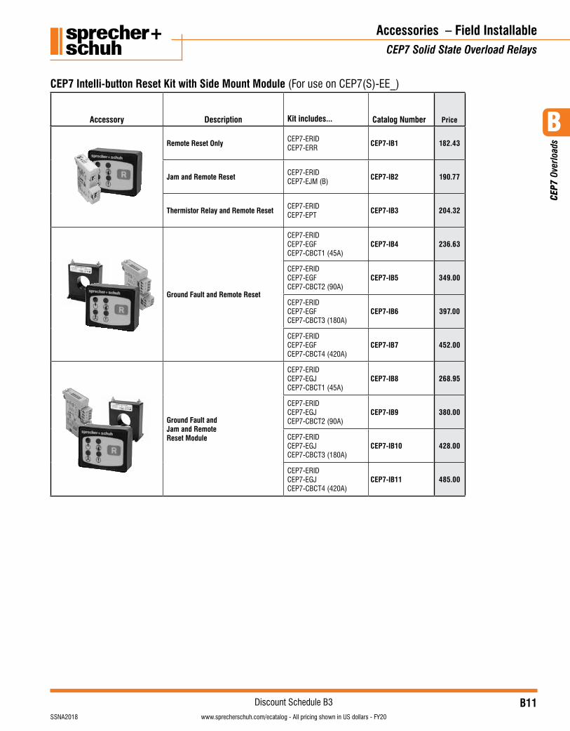
Accessory Description Kit includes... Catalog Number Price
Remote Reset Only CEP7-ERIDCEP7-ERR
CEP7-IB1 182.43
Jam and Remote Reset CEP7-ERIDCEP7-EJM (B)
CEP7-IB2 190.77
Thermistor Relay and Remote Reset CEP7-ERIDCEP7-EPT
CEP7-IB3 204.32
Ground Fault and Remote Reset
CEP7-ERIDCEP7-EGFCEP7-CBCT1 (45A)
CEP7-IB4 236.63
CEP7-ERIDCEP7-EGFCEP7-CBCT2 (90A)
CEP7-IB5 349.00
CEP7-ERIDCEP7-EGFCEP7-CBCT3 (180A)
CEP7-IB6 397.00
CEP7-ERIDCEP7-EGFCEP7-CBCT4 (420A)
CEP7-IB7 452.00
Ground Fault and Jam and Remote Reset Module
CEP7-ERIDCEP7-EGJCEP7-CBCT1 (45A)
CEP7-IB8 268.95
CEP7-ERIDCEP7-EGJCEP7-CBCT2 (90A)
CEP7-IB9 380.00
CEP7-ERIDCEP7-EGJCEP7-CBCT3 (180A)
CEP7-IB10 428.00
CEP7-ERIDCEP7-EGJCEP7-CBCT4 (420A)
CEP7-IB11 485.00
Accessories – Field InstallableCEP7 Solid State Overload Relays
CEP7 Intelli-button Reset Kit with Side Mount Module (For use on CEP7(S)-EE_)
B
CEP
7 Ov
erlo
ads
B12visit www.sprecherschuh.com/ecatalog for pricing and the most up to date information SSNA2018
Discount Schedule B3www.sprecherschuh.com/ecatalog - All pricing shown in US dollars - FY20
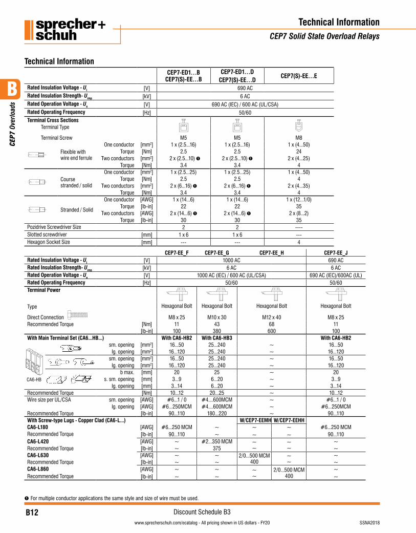
CEP7-ED1…B CEP7(S)-EE…B
CEP7-ED1…DCEP7(S)-EE…D
CEP7(S)-EE…E
Rated Insulation Voltage - UI [V] 690 AC Rated Insulation Strength- Uimp [kV] 6 ACRated Operation Voltage - Ue [V] 690 AC (IEC) / 600 AC (UL/CSA)Rated Operating Frequency [Hz] 50/60Terminal Cross Sections
Terminal Type
Terminal Screw M5 M5 M8
Flexible with wire end ferrule
One conductor [mm2] 1 x (2.5...16) 1 x (2.5...16) 1 x (4...50)Torque [Nm] 2.5 2.5 24
Two conductors [mm2] 2 x (2.5...10) ➊ 2 x (2.5...10) ➊ 2 x (4...25)Torque [Nm] 3.4 3.4 4
Course stranded / solid
One conductor [mm2] 1 x (2.5...25) 1 x (2.5...25) 1 x (4...50)Torque [Nm] 2.5 2.5 4
Two conductors [mm2] 2 x (6...16) ➊ 2 x (6...16) ➊ 2 x (4...35)Torque [Nm] 3.4 3.4 4
Stranded / Solid
One conductor [AWG] 1 x (14...6) 1 x (14...6) 1 x (12...1/0)Torque [lb-in] 22 22 35
Two conductors [AWG] 2 x (14...6) ➊ 2 x (14...6) ➊ 2 x (8...2)Torque [lb-in] 30 30 35
Pozidrive Screwdriver Size 2 2 ----Slotted screwdriver [mm] 1 x 6 1 x 6 ---Hexagon Socket Size [mm] --- --- 4
CEP7-EE_F CEP7-EE_G CEP7-EE_H CEP7-EE_JRated Insulation Voltage - UI [V] 1000 AC 690 ACRated Insulation Strength- Uimp [kV] 6 AC 6 ACRated Operation Voltage - Ue [V] 1000 AC (IEC) / 600 AC (UL/CSA) 690 AC (IEC)/600AC (UL)Rated Operating Frequency [Hz] 50/60 50/60Terminal Power
Type Hexagonal Bolt Hexagonal Bolt Hexagonal Bolt Hexagonal Bolt
Direct Connection M8 x 25 M10 x 30 M12 x 40 M8 x 25Recommended Torque [Nm] 11 43 68 11
[lb-in] 100 380 600 100With Main Terminal Set (CA6...HB...) With CA6-HB2 With CA6-HB3 With CA6-HB2
CA6-HB
sm. opening [mm2] 16...50 25...240 ~ 16...50lg. opening [mm2] 16...120 25...240 ~ 16...120
sm. opening [mm2] 16...50 25...240 ~ 16...50
lg. opening [mm2] 16...120 25...240 ~ 16...120
b max. [mm] 20 25 ~ 20s. sm. opening [mm] 3...9 6...20 ~ 3...9
lg. opening [mm] 3...14 6...20 ~ 3...14Recommended Torque [Nm] 10...12 20...25 ~ 10...12Wire size per UL/CSA sm. opening [AWG] #6...1 / 0 #4....600MCM ~ #6...1 / 0
lg. opening [AWG] #6...250MCM #4....600MCM ~ #6...250MCMRecommended Torque [lb-in] 90...110 180...220 ~ 90...110With Screw-type Lugs - Copper Clad (CA6-L...) W/CEP7-EEMH W/CEP7-EEHHCA6-L180 [AWG] #6...250 MCM ~ ~
~~~
#6...250 MCMRecommended Torque [lb-in] 90...110 ~ 90...110CA6-L420 [AWG] ~ #2...350 MCM ~
~~ ~
~Recommended Torque [lb-in] ~ 375 ~CA6-L630 [AWG] ~ ~ 2/0...500 MCM
400~ ~
~Recommended Torque [lb-in] ~ ~ ~CA6-L860 [AWG] ~ ~ ~
~2/0...500 MCM
400~
Recommended Torque [lb-in] ~ ~ ~
Technical Information
➊ For multiple conductor applications the same style and size of wire must be used.
Technical InformationCEP7 Solid State Overload Relays
B
CEP
7 Ov
erlo
ads
B13visit www.sprecherschuh.com/ecatalog for pricing and the most up to date informationSSNA2018
Discount Schedule B3www.sprecherschuh.com/ecatalog - All pricing shown in US dollars - FY20
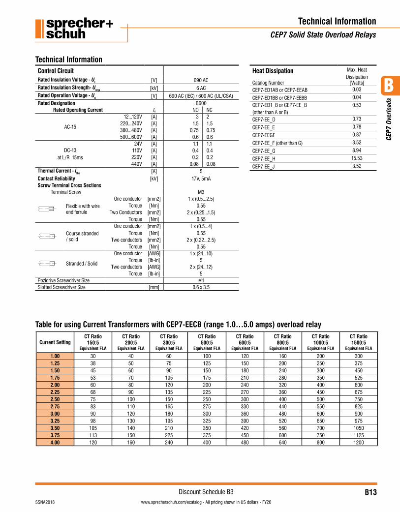
Control CircuitRated Insulation Voltage - UI [V] 690 ACRated Insulation Strength- Uimp [kV] 6 ACRated Operation Voltage - Ue [V] 690 AC (IEC) / 600 AC (UL/CSA)Rated Designation B600
Rated Operating Current Ie NO NC
AC-15
12...120V [A] 3 2220...240V [A] 1.5 1.5380...480V [A] 0.75 0.75500...600V [A] 0.6 0.6
DC-13at L/R 15ms
24V [A] 1.1 1.1110V [A] 0.4 0.4220V [A] 0.2 0.2440V [A] 0.08 0.08
Thermal Current - Ithe [A] 5Contact Reliability [kV] 17V, 5mAScrew Terminal Cross Sections
Terminal Screw M3
Flexible with wire end ferrule
One conductor [mm2] 1 x (0.5...2.5)Torque [Nm] 0.55
Two Conductors [mm2] 2 x (0.25...1.5)Torque [Nm] 0.55
Course stranded / solid
One conductor [mm2] 1 x (0.5...4)Torque [Nm] 0.55
Two conductors [mm2] 2 x (0.22...2.5)Torque [Nm] 0.55
Stranded / Solid
One conductor [AWG] 1 x (24...10)Torque [lb-in] 5
Two conductors [AWG] 2 x (24...12)Torque [lb-in] 5
Pozidrive Screwdriver Size #1Slotted Screwdriver Size [mm] 0.6 x 3.5
Technical InformationCEP7 Solid State Overload Relays
Technical Information
Current SettingCT Ratio
150:5Equivalent FLA
CT Ratio200:5
Equivalent FLA
CT Ratio300:5
Equivalent FLA
CT Ratio500:5
Equivalent FLA
CT Ratio600:5
Equivalent FLA
CT Ratio800:5
Equivalent FLA
CT Ratio1000:5
Equivalent FLA
CT Ratio1500:5
Equivalent FLA
1.001.251.501.752.002.252.502.753.003.253.503.754.00
30384553606875839098
105113120
405060708090
100110120130140150160
607590
105120135150165180195210225240
100125150175200225250275300325350375400
120150180210240270300330360390420450480
160200240280320360400440480520560600640
200250300350400450500550600650700750800
300375450525600675750825900975
105011251200
Table for using Current Transformers with CEP7-EECB (range 1.0…5.0 amps) overload relay
Heat Dissipation Max. Heat Dissipation
[Watts]Catalog NumberCEP7-ED1AB or CEP7-EEAB 0.03
CEP7-ED1BB or CEP7-EEBB 0.04
CEP7-ED1_B or CEP7-EE_B (other than A or B)
0.53
CEP7-EE_D 0.73
CEP7-EE_E 0.78
CEP7-EEGF 0.87
CEP7-EE_F (other than G) 3.52
CEP7-EE_G 8.94
CEP7-EE_H 15.53
CEP7-EE_J 3.52
B
CEP
7 Ov
erlo
ads
B14visit www.sprecherschuh.com/ecatalog for pricing and the most up to date information SSNA2018
Discount Schedule B3www.sprecherschuh.com/ecatalog - All pricing shown in US dollars - FY20
Technical InformationCEP7 Solid State Overload Relays
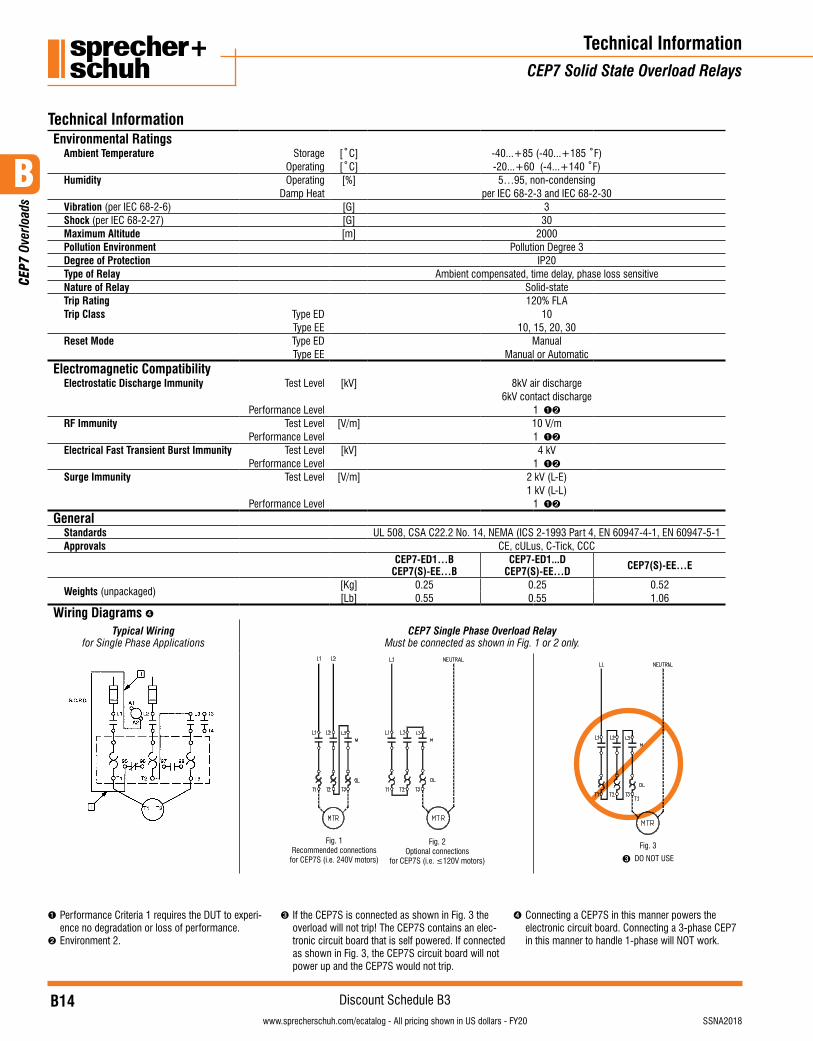
Technical InformationEnvironmental Ratings
Ambient Temperature Storage [˚C] -40...+85 (-40...+185 ˚F)Operating [˚C] -20...+60 (-4...+140 ˚F)
Humidity Operating [%] 5…95, non-condensingDamp Heat per IEC 68-2-3 and IEC 68-2-30
Vibration (per IEC 68-2-6) [G] 3Shock (per IEC 68-2-27) [G] 30Maximum Altitude [m] 2000Pollution Environment Pollution Degree 3Degree of Protection IP20Type of Relay Ambient compensated, time delay, phase loss sensitiveNature of Relay Solid-stateTrip Rating 120% FLATrip Class Type ED 10
Type EE 10, 15, 20, 30Reset Mode Type ED Manual
Type EE Manual or AutomaticElectromagnetic Compatibility
Electrostatic Discharge Immunity Test Level [kV] 8kV air discharge6kV contact discharge
Performance Level 1 ➊➋
RF Immunity Test Level [V/m] 10 V/mPerformance Level 1 ➊➋
Electrical Fast Transient Burst Immunity Test Level [kV] 4 kVPerformance Level 1 ➊➋
Surge Immunity Test Level [V/m] 2 kV (L-E)1 kV (L-L)
Performance Level 1 ➊➋
GeneralStandards UL 508, CSA C22.2 No. 14, NEMA (ICS 2-1993 Part 4, EN 60947-4-1, EN 60947-5-1Approvals CE, cULus, C-Tick, CCC
CEP7-ED1…BCEP7(S)-EE…B
CEP7-ED1...DCEP7(S)-EE…D CEP7(S)-EE…E
Weights (unpackaged)[Kg] 0.25 0.25 0.52[Lb] 0.55 0.55 1.06
Wiring Diagrams ➍Typical Wiring
for Single Phase ApplicationsCEP7 Single Phase Overload Relay
Must be connected as shown in Fig. 1 or 2 only.
Fig. 1Recommended connections
for CEP7S (i.e. 240V motors)
Fig. 2Optional connections
for CEP7S (i.e. ≤120V motors)
Fig. 3
➌ DO NOT USE
➊ Performance Criteria 1 requires the DUT to experi-ence no degradation or loss of performance.
➋ Environment 2.
➌ If the CEP7S is connected as shown in Fig. 3 the overload will not trip! The CEP7S contains an elec-tronic circuit board that is self powered. If connected as shown in Fig. 3, the CEP7S circuit board will not power up and the CEP7S would not trip.
➍ Connecting a CEP7S in this manner powers the electronic circuit board. Connecting a 3-phase CEP7 in this manner to handle 1-phase will NOT work.
B
CEP
7 Ov
erlo
ads
B15visit www.sprecherschuh.com/ecatalog for pricing and the most up to date informationSSNA2018
Discount Schedule B3www.sprecherschuh.com/ecatalog - All pricing shown in US dollars - FY20
Technical InformationCEP7 Solid State Overload Relays
Technical Information
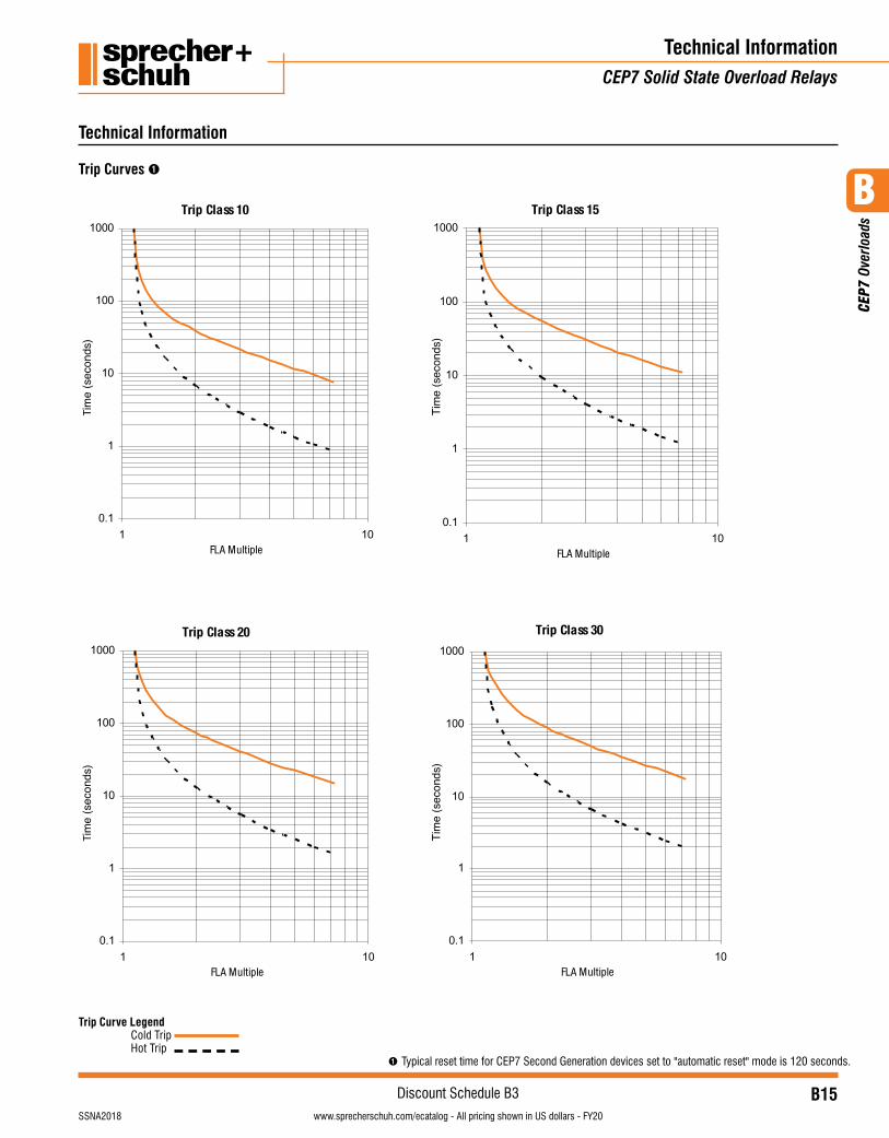
Trip Curve Legend Cold Trip Hot Trip
Trip Curves ➊
➊ Typical reset time for CEP7 Second Generation devices set to "automatic reset" mode is 120 seconds.
B
CEP
7 Ov
erlo
ads
B16visit www.sprecherschuh.com/ecatalog for pricing and the most up to date information SSNA2018
Discount Schedule B3www.sprecherschuh.com/ecatalog - All pricing shown in US dollars - FY20
Technical InformationCEP7 Solid State Overload Relays
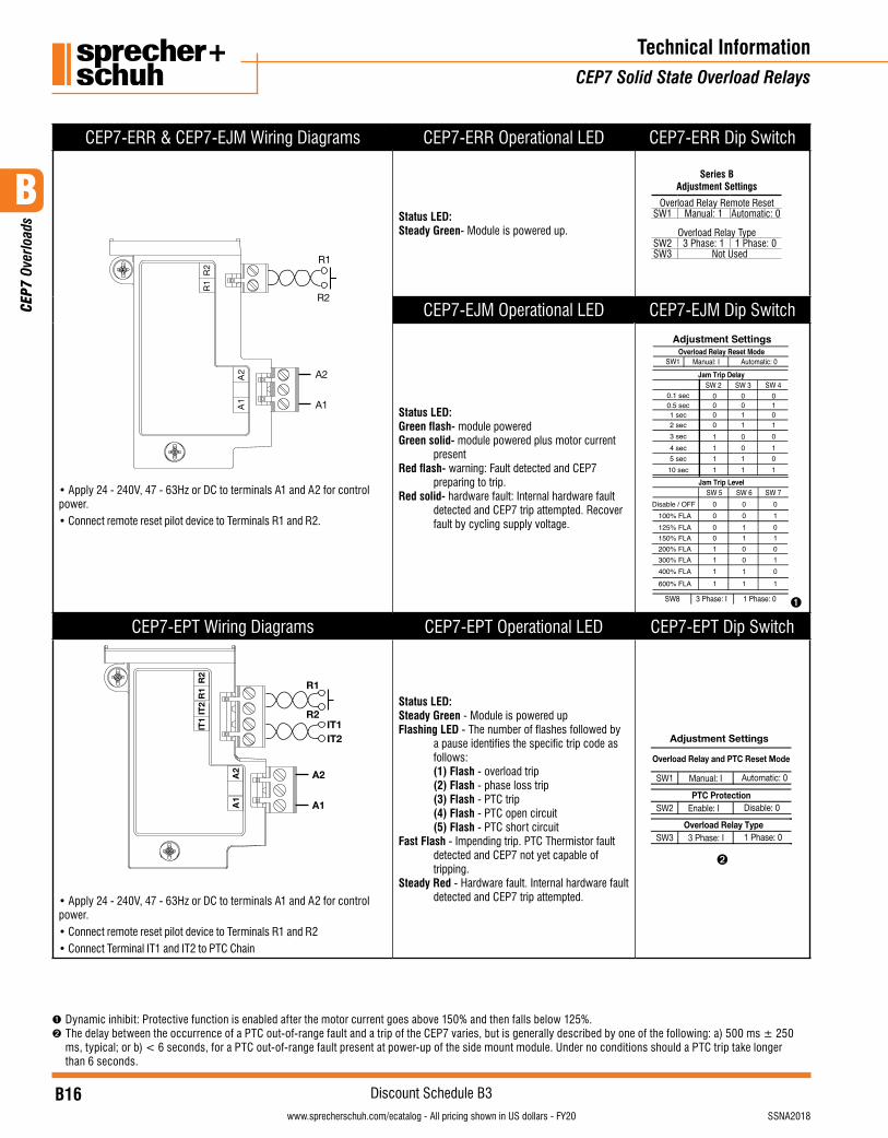
CEP7-ERR & CEP7-EJM Wiring Diagrams CEP7-ERR Operational LED CEP7-ERR Dip Switch
2R
1R
2A
1A A1
A2
R2
R1
• Apply 24 - 240V, 47 - 63Hz or DC to terminals A1 and A2 for control power.• Connect remote reset pilot device to Terminals R1 and R2.
Status LED: Steady Green- Module is powered up.
Series BAdjustment Settings
Overload Relay Remote ResetSW1 Manual: 1 Automatic: 0
Overload Relay TypeSW2 3 Phase: 1 1 Phase: 0SW3 Not Used
CEP7-EJM Operational LED CEP7-EJM Dip Switch
Status LED:Green flash- module poweredGreen solid- module powered plus motor current
presentRed flash- warning: Fault detected and CEP7
preparing to trip.Red solid- hardware fault: Internal hardware fault
detected and CEP7 trip attempted. Recover fault by cycling supply voltage.
Adjustment Settings
SW8 3 Phase: I 1 Phase: 0
SW1 Manual: I
SW 3SW 2
SW 5 SW 6 SW 7
SW 4
Overload Relay Reset Mode
Jam Trip Delay
Jam Trip Level
Automatic: 0
Disable / OFF100% FLA125% FLA150% FLA200% FLA300% FLA400% FLA600% FLA
0101010
1
0.1 sec0.5 sec1 sec2 sec3 sec4 sec5 sec10 sec
0000
1111
0011
0011
01010101
0000111
1
0011001
1
➊
CEP7-EPT Wiring Diagrams CEP7-EPT Operational LED CEP7-EPT Dip Switch
2R
1R
2TI
1TI
2A
1A A1
A2
R1
R2
IT2IT1
• Apply 24 - 240V, 47 - 63Hz or DC to terminals A1 and A2 for control power.• Connect remote reset pilot device to Terminals R1 and R2• Connect Terminal IT1 and IT2 to PTC Chain
Status LED: Steady Green - Module is powered up Flashing LED - The number of flashes followed by
a pause identifies the specific trip code as follows:
(1) Flash - overload trip (2) Flash - phase loss trip (3) Flash - PTC trip (4) Flash - PTC open circuit (5) Flash - PTC short circuitFast Flash - Impending trip. PTC Thermistor fault
detected and CEP7 not yet capable of tripping.
Steady Red - Hardware fault. Internal hardware fault detected and CEP7 trip attempted.
Adjustment Settings
SW1 Manual: I
SW2 Enable: I
Overload Relay and PTC Reset Mode
PTC ProtectionDisable: 0
Automatic: 0
SW3 3 Phase: IOverload Relay Type
1 Phase: 0
➋
➊ Dynamic inhibit: Protective function is enabled after the motor current goes above 150% and then falls below 125%. ➋ The delay between the occurrence of a PTC out-of-range fault and a trip of the CEP7 varies, but is generally described by one of the following: a) 500 ms ± 250
ms, typical; or b) < 6 seconds, for a PTC out-of-range fault present at power-up of the side mount module. Under no conditions should a PTC trip take longer than 6 seconds.
B
CEP
7 Ov
erlo
ads
B17visit www.sprecherschuh.com/ecatalog for pricing and the most up to date informationSSNA2018
Discount Schedule B3www.sprecherschuh.com/ecatalog - All pricing shown in US dollars - FY20
Technical InformationCEP7 Solid State Overload Relays
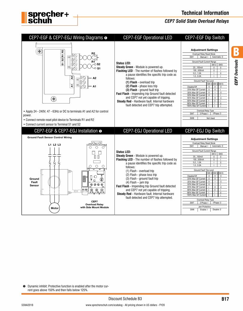
CEP7-EGF & CEP7-EGJ Wiring Diagrams ➊ CEP7-EGF Operational LED CEP7-EGF Dip Switch
2A
1A A1
A2
R1
R2
S1
S22
R1
R2
S1
S
• Apply 24 - 240V, 47 - 63Hz or DC to terminals A1 and A2 for control power.• Connect remote reset pilot device to Terminals R1 and R2• Connect current sensor to Terminal S1 and S2
Status LED: Steady Green - Module is powered up.Flashing LED - The number of flashes followed by
a pause identifies the specific trip code as follows:
(1) Flash - overload trip (2) Flash - phase loss trip (3) Flash - ground fault tripFast Flash - Impending trip Ground fault detected
and CEP7 not yet capable of tripping. Steady Red - Hardware fault. Internal hardware
fault detected and CEP7 trip attempted.
Adjustment Settings
SW1 Manual: I
SW 2 SW30 00 II 0I I
SW 4 SW 6SW 50 0
00
0 I00IIII
0
0
II I
I
III00
0
20...100mA100...500mA0.2...1.0A1.0...5.0A
Overload Relay Reset Mode
Ground Fault Current Range
Ground Fault Trip Level
Automatic: 0
SW7 3 Phase: I Overload Relay Type
1Phase: 0
SW8 Not Used
Disable/Off20% Max GF Current35% Max GF Current50% Max GF Current65% Max GF Current80% Max GF Current90% Max GF Current100% Max GF Current
CEP7-EGF & CEP7-EGJ Installation ➊ CEP7-EGJ Operational LED CEP7-EGJ Dip SwitchGround Fault Sensor Control Wiring
Motor
L2 L3L1
GroundFault
Sensor
CEP7Overload Relay
with Side Mount Module
S1 S2
Status LED: Steady Green - Module is powered up.Flashing LED - The number of flashes followed by
a pause identifies the specific trip code as follows:
(1) Flash - overload trip (2) Flash - phase loss trip (3) Flash - ground fault trip (4) Flash – jam tripFast Flash - Impending trip Ground fault detected
and CEP7 not yet capable of tripping. Steady Red - Hardware fault. Internal hardware
fault detected and CEP7 trip attempted.
SW8 Enable: I Jam Protection
Disable: 0
Adjustment Settings
SW1 Manual: I
SW 2 SW30 00 II 0I I
SW 4 SW 6SW 50 0
00
0 I00IIII
0
0
II I
I
III00
0
20...100mA100...500mA0.2...1.0A1.0...5.0A
Overload Relay Reset Mode
Ground Fault Current Range
Ground Fault Trip Level
Automatic: 0
SW7 3 Phase: I Overload Relay Type
1Phase: 0
Disable/Off20% Max GF Current35% Max GF Current50% Max GF Current65% Max GF Current80% Max GF Current90% Max GF Current100% Max GF Current
➊ Dynamic inhibit: Protective function is enabled after the motor cur-rent goes above 150% and then falls below 125%.
B
CEP
7 Ov
erlo
ads
B18visit www.sprecherschuh.com/ecatalog for pricing and the most up to date information SSNA2018
Discount Schedule B3www.sprecherschuh.com/ecatalog - All pricing shown in US dollars - FY20
Technical InformationCEP7 Network Communicating Module
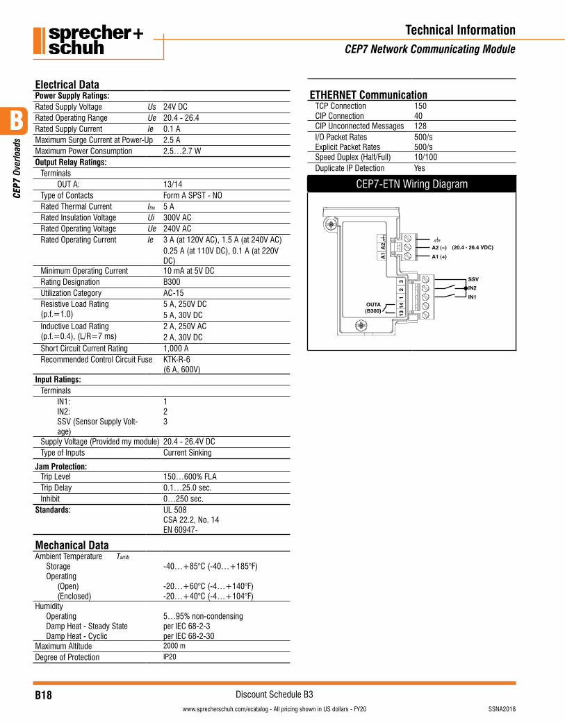
Electrical DataPower Supply Ratings:Rated Supply Voltage Us 24V DCRated Operating Range Ue 20.4 - 26.4Rated Supply Current Ie 0.1 AMaximum Surge Current at Power-Up 2.5 AMaximum Power Consumption 2.5…2.7 WOutput Relay Ratings:
TerminalsOUT A: 13/14
Type of Contacts Form A SPST - NORated Thermal Current Ithe 5 ARated Insulation Voltage Ui 300V ACRated Operating Voltage Ue 240V ACRated Operating Current Ie 3 A (at 120V AC), 1.5 A (at 240V AC)
0.25 A (at 110V DC), 0.1 A (at 220V DC)
Minimum Operating Current 10 mA at 5V DCRating Designation B300Utilization Category AC-15Resistive Load Rating(p.f.=1.0)
5 A, 250V DC5 A, 30V DC
Inductive Load Rating(p.f.=0.4), (L/R=7 ms)
2 A, 250V AC2 A, 30V DC
Short Circuit Current Rating 1,000 ARecommended Control Circuit Fuse KTK-R-6
(6 A, 600V)Input Ratings:
TerminalsIN1:IN2:SSV (Sensor Supply Volt-age)
123
Supply Voltage (Provided my module) 20.4 - 26.4V DCType of Inputs Current Sinking
Jam Protection:Trip Level 150…600% FLATrip Delay 0.1…25.0 sec.Inhibit 0…250 sec.
Standards: UL 508CSA 22.2, No. 14EN 60947-
Mechanical DataAmbient Temperature Tamb
StorageOperating
(Open)(Enclosed)
-40…+85°C (-40…+185°F)
-20…+60°C (-4…+140°F)-20…+40°C (-4…+104°F)
HumidityOperatingDamp Heat - Steady StateDamp Heat - Cyclic
5…95% non-condensingper IEC 68-2-3per IEC 68-2-30
Maximum Altitude 2000 m
Degree of Protection IP20
ETHERNET CommunicationTCP ConnectionCIP Connection
15040
CIP Unconnected Messages 128I/O Packet RatesExplicit Packet Rates
500/s500/s
Speed Duplex (Half/Full) 10/100Duplicate IP Detection Yes
CEP7-ETN Wiring Diagram
OUTA(B300) 13
141
23 SSV
IN2IN1
A1 (+)A2 (-) (20.4 - 26.4 VDC)
A1
A2
B
CEP
7 Ov
erlo
ads
B19visit www.sprecherschuh.com/ecatalog for pricing and the most up to date informationSSNA2018
Discount Schedule B3www.sprecherschuh.com/ecatalog - All pricing shown in US dollars - FY20
Technical Information/DimensionsCEP7 Solid State Overload Relays
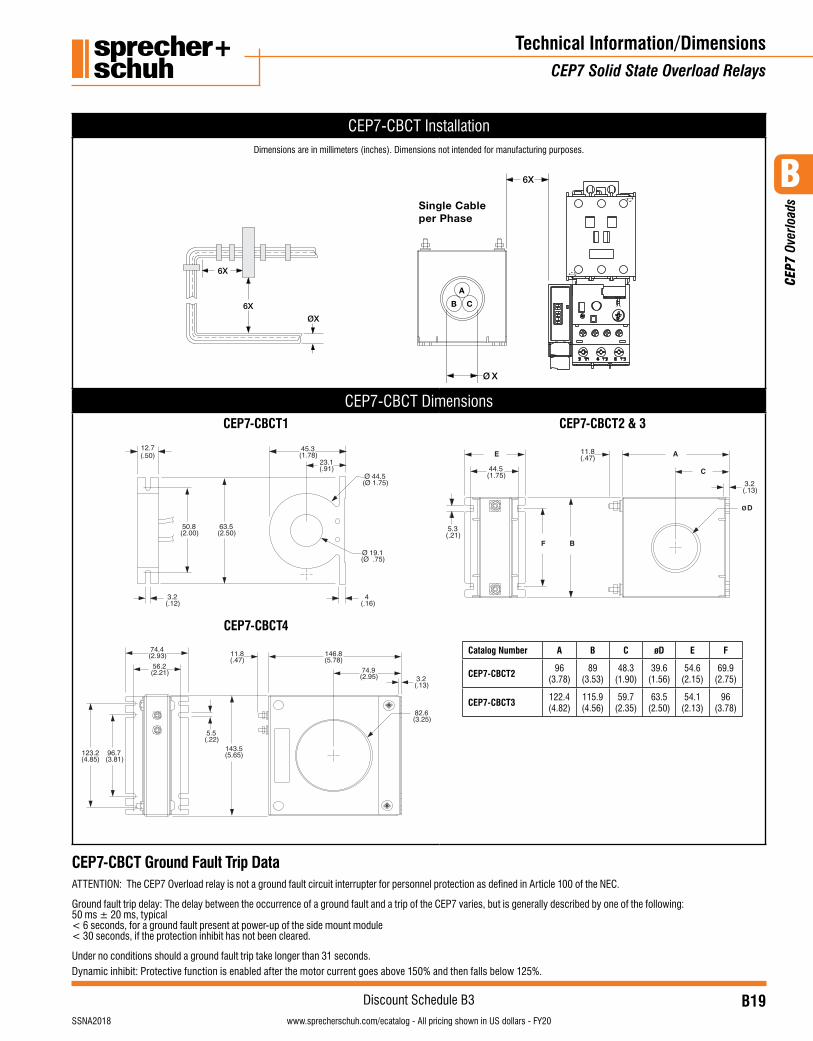
CEP7-CBCT Installation
6X
6X
ØX
6X
Ø X
Single Cable per Phase
A
B C
CEP7-CBCT DimensionsCEP7-CBCT1
11.8(.47)
3.2(.13)
45.3(1.78)
23.1(.91)
¯ 19.1(¯ .75)
¯ 44.5(¯ 1.75)
D
63.5(2.50)
50.8(2.00)
3.2(.12)
4(.16)
5.3(.21)
12.7(.50)
E
F B
A
C
96(3.78)
CAT
CEP7-CBCT2
A
89.6(3.53)
B
48.3(1.90)
CDimensions
39.6(1.56)
¿ D
54.6(2.15)
E
69.9(2.75)
122.4(4.82)CEP7-CBCT3 115.9
(4.56)59.7
(2.35)63.5
(2.50)54.1
(2.13)96
(3.78)
F
44.5(1.75)
56.2(2.21)
74.4(2.93)
123.2(4.85)
96.7(3.81)
CEP7-CBCT2CEP7-CBCT3
CEP7-CBCT4
CEP7-CBCT1
11.8(.47)
146.8(5.78)
143.5(5.65)
5.5(.22)
74.9(2.95) 3.2
(.13)
82.6(3.25)
CEP7-CBCT4
11.8(.47)
3.2(.13)
45.3(1.78)
23.1(.91)
¯ 19.1(¯ .75)
¯ 44.5(¯ 1.75)
D
63.5(2.50)
50.8(2.00)
3.2(.12)
4(.16)
5.3(.21)
12.7(.50)
E
F B
A
C
96(3.78)
CAT
CEP7-CBCT2
A
89.6(3.53)
B
48.3(1.90)
CDimensions
39.6(1.56)
¿ D
54.6(2.15)
E
69.9(2.75)
122.4(4.82)CEP7-CBCT3 115.9
(4.56)59.7
(2.35)63.5
(2.50)54.1
(2.13)96
(3.78)
F
44.5(1.75)
56.2(2.21)
74.4(2.93)
123.2(4.85)
96.7(3.81)
CEP7-CBCT2CEP7-CBCT3
CEP7-CBCT4
CEP7-CBCT1
11.8(.47)
146.8(5.78)
143.5(5.65)
5.5(.22)
74.9(2.95) 3.2
(.13)
82.6(3.25)
CEP7-CBCT2 & 3
11.8(.47)
3.2(.13)
45.3(1.78)
23.1(.91)
¯ 19.1(¯ .75)
¯ 44.5(¯ 1.75)
D
63.5(2.50)
50.8(2.00)
3.2(.12)
4(.16)
5.3(.21)
12.7(.50)
E
F B
A
C
96(3.78)
CAT
CEP7-CBCT2
A
89.6(3.53)
B
48.3(1.90)
CDimensions
39.6(1.56)
¿ D
54.6(2.15)
E
69.9(2.75)
122.4(4.82)CEP7-CBCT3 115.9
(4.56)59.7
(2.35)63.5
(2.50)54.1
(2.13)96
(3.78)
F
44.5(1.75)
56.2(2.21)
74.4(2.93)
123.2(4.85)
96.7(3.81)
CEP7-CBCT2CEP7-CBCT3
CEP7-CBCT4
CEP7-CBCT1
11.8(.47)
146.8(5.78)
143.5(5.65)
5.5(.22)
74.9(2.95) 3.2
(.13)
82.6(3.25)
Catalog Number A B C øD E F
CEP7-CBCT2 96(3.78)
89(3.53)
48.3(1.90)
39.6(1.56)
54.6(2.15)
69.9(2.75)
CEP7-CBCT3 122.4(4.82)
115.9(4.56)
59.7(2.35)
63.5(2.50)
54.1(2.13)
96(3.78)
CEP7-CBCT Ground Fault Trip Data ATTENTION: The CEP7 Overload relay is not a ground fault circuit interrupter for personnel protection as defined in Article 100 of the NEC.
Ground fault trip delay: The delay between the occurrence of a ground fault and a trip of the CEP7 varies, but is generally described by one of the following: 50 ms ± 20 ms, typical < 6 seconds, for a ground fault present at power-up of the side mount module < 30 seconds, if the protection inhibit has not been cleared.
Under no conditions should a ground fault trip take longer than 31 seconds.Dynamic inhibit: Protective function is enabled after the motor current goes above 150% and then falls below 125%.
Dimensions are in millimeters (inches). Dimensions not intended for manufacturing purposes.
B
CEP
7 Ov
erlo
ads
B20visit www.sprecherschuh.com/ecatalog for pricing and the most up to date information SSNA2018
Discount Schedule B3www.sprecherschuh.com/ecatalog - All pricing shown in US dollars - FY20
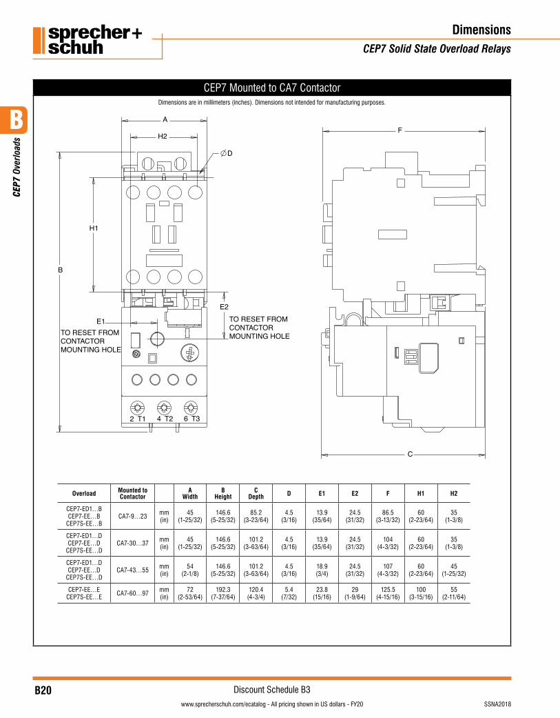
CEP7 Mounted to CA7 Contactor
Overload Mounted to Contactor
AWidth
BHeight
CDepth D E1 E2 F H1 H2
CEP7-ED1…BCEP7-EE…B
CEP7S-EE…BCA7-9…23 mm
(in)45
(1-25/32)146.6
(5-25/32)85.2
(3-23/64)4.5
(3/16)13.9
(35/64)24.5
(31/32)86.5
(3-13/32)60
(2-23/64)35
(1-3/8)
CEP7-ED1…DCEP7-EE…D
CEP7S-EE…DCA7-30…37 mm
(in)45
(1-25/32)146.6
(5-25/32)101.2
(3-63/64)4.5
(3/16)13.9
(35/64)24.5
(31/32)104
(4-3/32)60
(2-23/64)35
(1-3/8)
CEP7-ED1…DCEP7-EE…D
CEP7S-EE…DCA7-43…55 mm
(in)54
(2-1/8)146.6
(5-25/32)101.2
(3-63/64)4.5
(3/16)18.9(3/4)
24.5(31/32)
107(4-3/32)
60(2-23/64)
45(1-25/32)
CEP7-EE…ECEP7S-EE…E CA7-60…97 mm
(in)72
(2-53/64)192.3
(7-37/64)120.4
(4-3/4)5.4
(7/32)23.8
(15/16)29
(1-9/64)125.5
(4-15/16)100
(3-15/16)55
(2-11/64)
DimensionsCEP7 Solid State Overload Relays
Dimensions are in millimeters (inches). Dimensions not intended for manufacturing purposes.

B
CEP
7 Ov
erlo
ads
B21visit www.sprecherschuh.com/ecatalog for pricing and the most up to date informationSSNA2018
Discount Schedule B3www.sprecherschuh.com/ecatalog - All pricing shown in US dollars - FY20
Dimensions/TechnicalCEP7 Solid State Overload Relays
CEP7 Pass-thru Overload
44.8
35
13.9
(.18 ø)ø 4.5
3.589
(2.31)58.6
(1.97)50
(1.44)36.7
(1.76)
(1.38)
(.55)
(.14)(3.50)
CEP7-ERID Remote Indicator
R1
R2
R1
R2
A1
A2
A1
A2CEP7-ERID is to be used with Series B or later:CEP7-EJMCEP7-ERRCEP7-EPTCEP7-EGFCEP7-EGJ
0.56 - 0.79 N.m(5 - 7 lb-in)
7mm(.28 in)
0.6mm X 3.5mm Blade(.02 in X .14 in Blade)
Function edoC hsalFsutatS ro tluaF.D.E.LModule Power Green (Flash)
Overload Trip Red (Solid)
Overload Warning (> 110%) Yellow (Flash)
Phase Loss Trip Red (Solid)
Module Power + Motor Current Green (Solid)Hardware Fault Red (Solid)
Ground Fault Trip 1 RedJam Trip 2 RedPTC Trip 3 Red
Fault Detected Red (Rapid)
11
2
Reset4
3
Module Power / Status
2 Overload
3 Phase Loss
4 Fault Status
FAULT CODE
Starter:
1- GROUND FAULT
2- JAM 3- PTC
(1.81)46
(.69)17.5
(.57)14.5
(1.50)38
200 ft max.
22mm hole
LED Indicators
Operating Temperatures -20¼C É 60¼C (-4¼F É +140¼F)Storage Temperatures -40¼C É 85¼C (-4¼F É +185¼F)
Dimensions are in millimeters (inches). Dimensions not intended for manufacturing purposes.
B
CEP
7 Ov
erlo
ads
B22visit www.sprecherschuh.com/ecatalog for pricing and the most up to date information SSNA2018
Discount Schedule B3www.sprecherschuh.com/ecatalog - All pricing shown in US dollars - FY20
DimensionsCEP7 Solid State Overload Relays
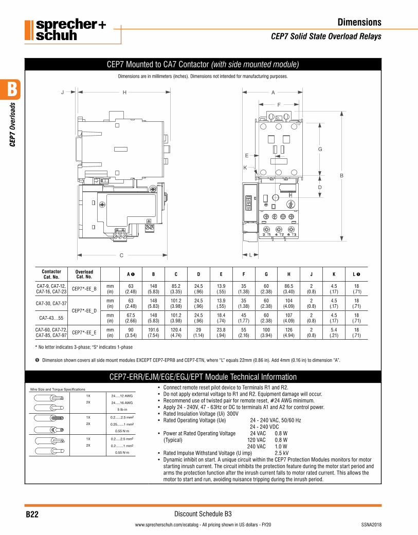
CEP7 Mounted to CA7 Contactor (with side mounted module)
A
F
G
B
D
E
K
L
H
C
J
Contactor Cat. No.
Overload Cat. No. A ➊ B C D E F G H J K L ➊
CA7-9, CA7-12, CA7-16, CA7-23 CEP7*-EE_B mm
(in)63
(2.48)148
(5.83)85.2
(3.35)24.5(.96)
13.9(.55)
35(1.38)
60(2.38)
86.5(3.40)
2(0.8)
4.5 (.17)
18 (.71)
CA7-30, CA7-37
CEP7*-EE_D
mm (in)
63 (2.48)
148(5.83)
101.2(3.98)
24.5(.96)
13.9(.55)
35(1.38)
60(2.38)
104(4.09)
2(0.8)
4.5 (.17)
18 (.71)
CA7-43…55 mm (in)
67.5 (2.66)
148(5.83)
101.2(3.98)
24.5(.96)
18.4(.74)
45(1.77)
60(2.38)
107(4.09)
2(0.8)
4.5 (.17)
18 (.71)
CA7-60, CA7-72, CA7-85, CA7-97 CEP7*-EE_E mm
(in)90
(3.54)191.6(7.54)
120.4(4.74)
29(1.14)
23.8(.94)
55(2.16)
100(3.94)
126(4.94)
2(0.8)
5.4 (.21)
18 (.71)
* No letter indicates 3-phase; "S" indicates 1-phase
➊ Dimension shown covers all side mount modules EXCEPT CEP7-EPRB and CEP7-ETN, where “L” equals 22mm (0.86 in). Add 4mm (0.16 in) to dimension “A”.
CEP7-ERR/EJM/EGE/EGJ/EPT Module Technical InformationWire Size and Torque Specifications
1X
2X
24.....12 AWG
24.....16 AWG
5 lb-in
1X
2X
0.2......2.5 mm2
0.25.......1 mm2
0.55 N.m
1X
2X
0.2.....2.5 mm2
0.2........1 mm2
0.55 N.m
• Connect remote reset pilot device to Terminals R1 and R2.• Do not apply external voltage to R1 and R2. Equipment damage will occur.• Recommend use of twisted pair for remote reset, #24 AWG minimum.• Apply 24 - 240V, 47 - 63Hz or DC to terminals A1 and A2 for control power.• Rated Insulation Voltage (Ui) 300V• Rated Operating Voltage (Ue) 24 - 240 VAC, 50/60 Hz
24 - 240 VDC• Power at Rated Operating Voltage 24 VAC 0.8 W
(Typical) 120 VAC 0.8 W 240 VAC 1.0 W
• Rated Impulse Withstand Voltage (U imp) 2.5 kV• Dynamic inhibit on start. A unique circuit within the CEP7 Protection Modules monitors for motor
starting inrush current. The circuit inhibits the protection feature during the motor start period and arms the protection function after the inrush current falls to motor rated current. This allows the motor to start and run, avoiding nuisance tripping during the inrush period.
Dimensions are in millimeters (inches). Dimensions not intended for manufacturing purposes.
B
CEP
7 Ov
erlo
ads
B23visit www.sprecherschuh.com/ecatalog for pricing and the most up to date informationSSNA2018
Discount Schedule B3www.sprecherschuh.com/ecatalog - All pricing shown in US dollars - FY20
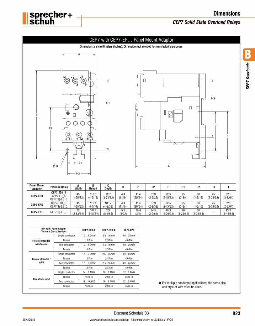
CEP7 with CEP7-EP… Panel Mount Adaptor
DimensionsCEP7 Solid State Overload Relays
Dimensions are in millimeters (inches). Dimensions not intended for manufacturing purposes.
Panel Mount Adaptor Overload Relay A
WidthB
HeightC
Depth D E1 E2 F H1 H2 H3 J
CEP7-EPBCEP7-ED1_BCEP7-ED_B
CEP7(S)-EE_B
45(1-25/32)
116.5(4-9/16)
92.7(3-21/32)
4.4(11/64)
11.4(29/64)
57.9(2-9/32)
62.5(2-15/32)
95(3-3/4)
30(1-3/16)
75(2-31/32)
52.1(2-3/64)
CEP7-EPD CEP7-ED1_DCEP7(S)-EE_D
45(1-25/32)
112.4(4-7/16)
108.7(4-9/32)
4.4(11/64)
11.4(29/64)
57.9(2-9/32)
62.5(2-15/32)
95(3-3/4)
30(1-3/16)
75(2-31/32)
52.1(2-3/64)
CEP7-EPE CEP7(S)-EE_E 72(2-53/64)
107.4(4-15/64)
127(5-1/64)
5.5(5/32)
26.4(3/4)
54.5(2-9/64)
48.3(1-29/32)
90(3-23/64)
60(2-23/64) ~ 43.3
(1-45/64)
DIN-rail / Panel Adapter Terminal Cross Sections CEP7-EPB ➊ CEP7-EPD ➊ CEP7-EPE
Flexible stranded with ferrule
Single conductor 1.0…4.0mm2 2.5…16mm2 4.0…35mm2
Torque 1.8 Nm 2.3 Nm 4.0 Nm
Two conductor 1.0…4.0mm2 2.5…10mm2 4.0…25mm2
Torque 1.8 Nm 2.3 Nm 4.0 Nm
Course stranded / solid
Single conductor 1.5…6.0mm2 2.5…25mm2 4.0…50mm2
Torque 1.8 Nm 2.3 Nm 4.0 Nm
Two conductor 1.5…6.0mm2 2.5…16mm2 4.0…35mm2
Torque 1.8 Nm 2.3 Nm 4.0 Nm
Stranded / solid
Single conductor 14…8 AWG 16…6 AWG 12…1 AWG
Torque 16 lb-in 20 lb-in 35 lb-in
Two conductor 14…10 AWG 16…6 AWG 12…2 AWG
Torque 16 lb-in 20 lb-in 35 lb-in➊ For multiple conductor applications, the same size
and style of wire must be used.
Dimensions are in millimeters (inches). Dimensions not intended for manufacturing purposes.
B
CEP
7 Ov
erlo
ads
B24visit www.sprecherschuh.com/ecatalog for pricing and the most up to date information SSNA2018
Discount Schedule B3www.sprecherschuh.com/ecatalog - All pricing shown in US dollars - FY20
F
I
J
BC
D
A
E
G
H
KL
B
I
A
K
45(1.77)
53(2.087)
G
LF
C
D
EH
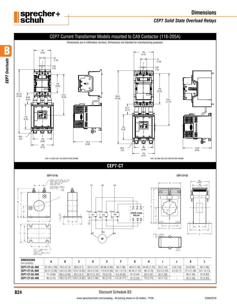
CEP7 Current Transformer Models mounted to CA9 Contactor (116-205A)Dimensions are in millimeters (inches). Dimensions not intended for manufacturing purposes.
30[1.18]
100[3.94]
135[5.32]
100[3.94]
90[3.54]
120[4.72]
341,23[13.43]
219,1[8.63]
3,58[.14]
Ø5,5[.22]
35[1.38]
165[6.50]
279,7[11.01]
3,58[.14]
100[3.94]
135[5.32]
59,46[2.34]
55,11[2.17]
120[4.72]
[.22]
105[4.13]
392,3[15.45]
152,8[6.02]
152,8[6.02]
CA9-116 AND CA9-146 CONTACTORS SHOWN CA9-190 AND CA9-205 CONTACTORS SHOWN
Ø5,5
CEP7-CT
DimensionsCEP7 Solid State Overload Relays
M
OVER LOADRELAY
L1
L1
T1 T2 T3
L2 L3
L2 L3
H1(Dot) H1(Dot) H1(Dot)
H2 H2 H2
X1 1X1X
X2X2X2CT1
T1 T2T3
CT2 CT3
DIMENSIONS mm (inches) A B C D E F G H I J K L
CEP7-CT-UL-300 27.29 (1.09) 79.5 (3.13) 68.6 (2.7) 32.5 (1.27) 60.96 (2.40) 50 (1.96) 40.4 (1.59) 44.45 (1.75) 29 (1.14) 3 (0.118) 24 (0.94) 50 (1.96)CEP7-CT-UL-600 83.31 (3.28) 134.4 (5.29) 123.2 (4.85) 59.4 (2.34) 115.8 (4.56) 54.1 (2.13) 44.45 (1.75) 96 (3.78) 63.5 (2.50) 4.3 (0.17) 27.4 (1.08) 54.1 (2.13)CEP7-CT-CE-300 71 (2.80) 88.5 (3.48) 85.5 (2.7) 36.75 (1.27) 70 (2.75) 6.5 (0.26) 57 (2.24) 50 (1.97) 32 (1.26) 40 (1.58) 72 (2.83)CEP7-CT-CE-400 96 (3.75) 108.5 (4.27) 105.5 (4.85) 48.3 (1.90) 95 (3.74) 4.5 (0.177) 57 (2.24) 70 (3.75) 44 (1.73) ~ 40 (1.58) 72 (2.83)
CEP7-CT-CECEP7-CT-UL
B
CEP
7 Ov
erlo
ads
B25visit www.sprecherschuh.com/ecatalog for pricing and the most up to date informationSSNA2018
Discount Schedule B3www.sprecherschuh.com/ecatalog - All pricing shown in US dollars - FY20
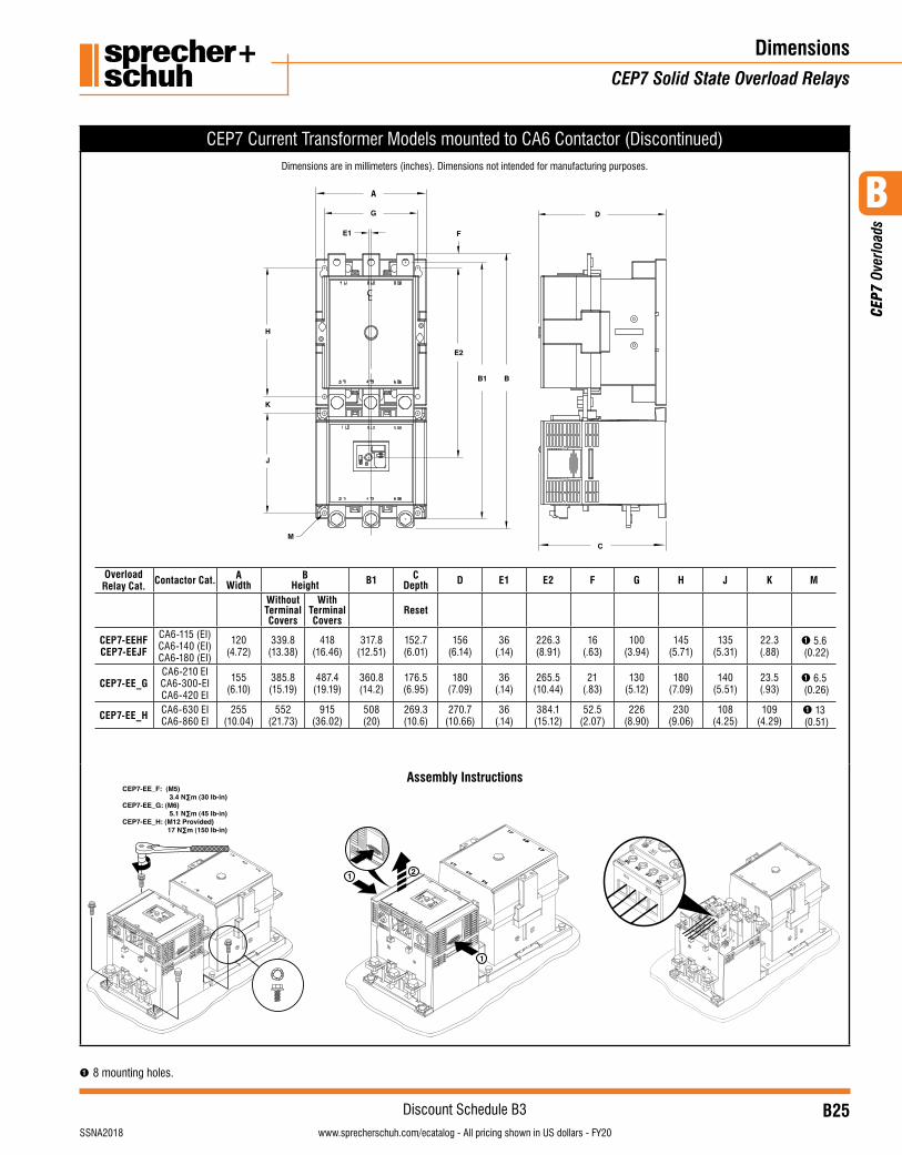
CEP7 Current Transformer Models mounted to CA6 Contactor (Discontinued)
A
Overload Relay Cat. Contactor Cat. A
WidthB
Height B1 CDepth D E1 E2 F G H J K M
Without Terminal Covers
With Terminal Covers
Reset
CEP7-EEHFCEP7-EEJF
CA6-115 (EI)CA6-140 (EI) CA6-180 (EI)
120(4.72)
339.8(13.38)
418(16.46)
317.8(12.51)
152.7 (6.01)
156(6.14)
36(.14)
226.3(8.91)
16(.63)
100(3.94)
145(5.71)
135(5.31)
22.3(.88)
➊ 5.6 (0.22)
CEP7-EE_G CA6-210 EICA6-300-EI CA6-420 EI
155(6.10)
385.8(15.19)
487.4(19.19)
360.8(14.2)
176.5(6.95)
180(7.09)
36(.14)
265.5(10.44)
21(.83)
130(5.12)
180(7.09)
140 (5.51)
23.5(.93)
➊ 6.5 (0.26)
CEP7-EE_H CA6-630 EI CA6-860 EI
255(10.04)
552(21.73)
915(36.02)
508(20)
269.3(10.6)
270.7(10.66)
36(.14)
384.1(15.12)
52.5(2.07)
226(8.90)
230(9.06)
108 (4.25)
109(4.29)
➊ 13 (0.51)
Assembly Instructions CEP7-EE_F: (M5) 3.4 N∑m (30 lb-in)CEP7-EE_G: (M6) 5.1 N∑m (45 lb-in)CEP7-EE_H: (M12 Provided) 17 N∑m (150 lb-in)
95 96
97 98
1
1
2
Dimensions are in millimeters (inches). Dimensions not intended for manufacturing purposes.
DimensionsCEP7 Solid State Overload Relays
➊ 8 mounting holes.

B
CEP
7 Ov
erlo
ads
B26visit www.sprecherschuh.com/ecatalog for pricing and the most up to date information SSNA2018
Discount Schedule B3www.sprecherschuh.com/ecatalog - All pricing shown in US dollars - FY20
DimensionsCEP7 Solid State Overload Relays
Notes
B27visit www.sprecherschuh.com/ecatalog for pricing and the most up to date informationSSNA2018
B
CEP
9 Ov
erlo
ads
www.sprecherschuh.com/ecatalog - All pricing shown in US dollars - FY20
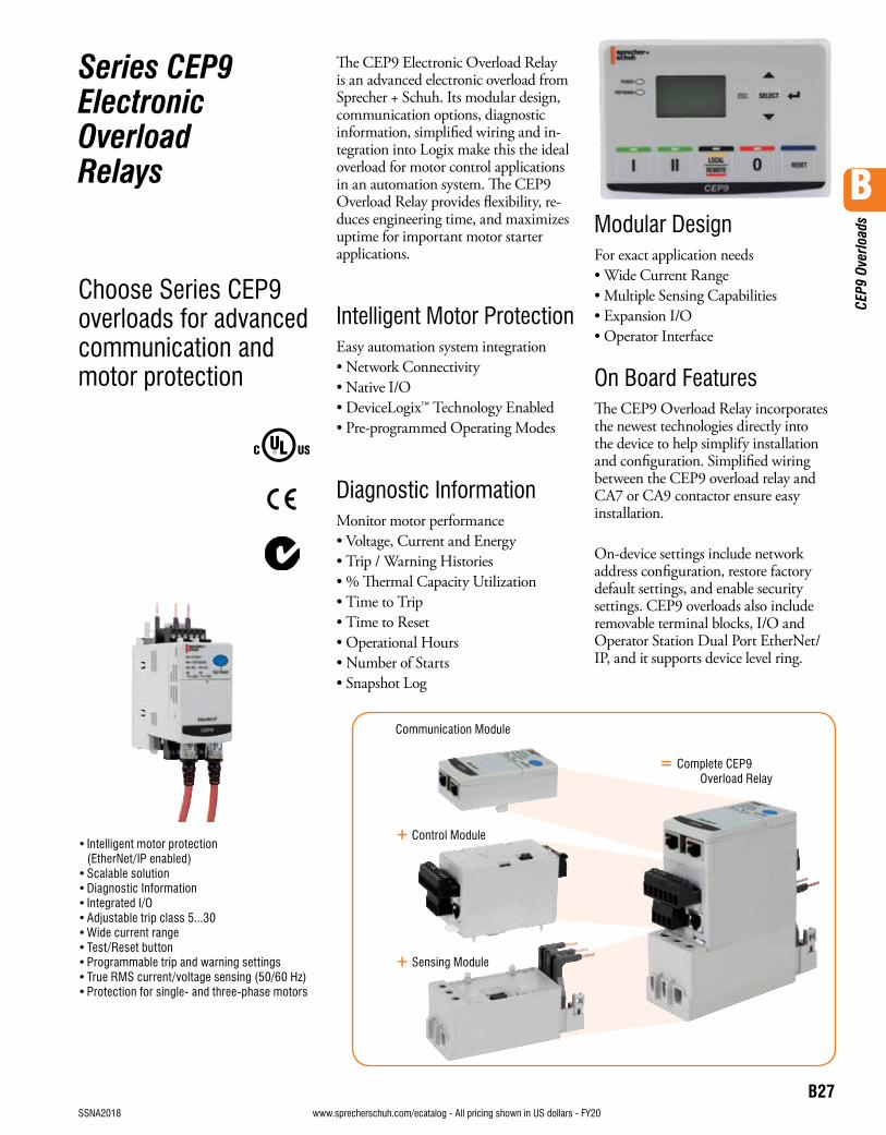
Series CEP9 Electronic Overload Relays
Choose Series CEP9 overloads for advanced communication and motor protection
The CEP9 Electronic Overload Relay is an advanced electronic overload from Sprecher + Schuh. Its modular design, communication options, diagnostic information, simplified wiring and in-tegration into Logix make this the ideal overload for motor control applications in an automation system. The CEP9 Overload Relay provides flexibility, re-duces engineering time, and maximizes uptime for important motor starter applications.
Intelligent Motor ProtectionEasy automation system integration• Network Connectivity• Native I/O• DeviceLogix™ Technology Enabled• Pre-programmed Operating Modes
Diagnostic InformationMonitor motor performance• Voltage, Current and Energy• Trip / Warning Histories• % Thermal Capacity Utilization• Time to Trip• Time to Reset• Operational Hours• Number of Starts• Snapshot Log
Modular DesignFor exact application needs• Wide Current Range• Multiple Sensing Capabilities• Expansion I/O• Operator Interface
On Board FeaturesThe CEP9 Overload Relay incorporates the newest technologies directly into the device to help simplify installation and configuration. Simplified wiring between the CEP9 overload relay and CA7 or CA9 contactor ensure easy installation.
On-device settings include network address configuration, restore factory default settings, and enable security settings. CEP9 overloads also include removable terminal blocks, I/O and Operator Station Dual Port EtherNet/IP, and it supports device level ring.
• Intelligent motor protection (EtherNet/IP enabled)
• Scalable solution• Diagnostic Information• Integrated I/O• Adjustable trip class 5...30• Wide current range• Test/Reset button• Programmable trip and warning settings• True RMS current/voltage sensing (50/60 Hz)• Protection for single- and three-phase motors
Communication Module
+ Control Module
+ Sensing Module
= Complete CEP9 Overload Relay
B28visit www.sprecherschuh.com/ecatalog for pricing and the most up to date information SSNA2018
B
CEP
9 Ov
erlo
ads
www.sprecherschuh.com/ecatalog - All pricing shown in US dollars - FY20
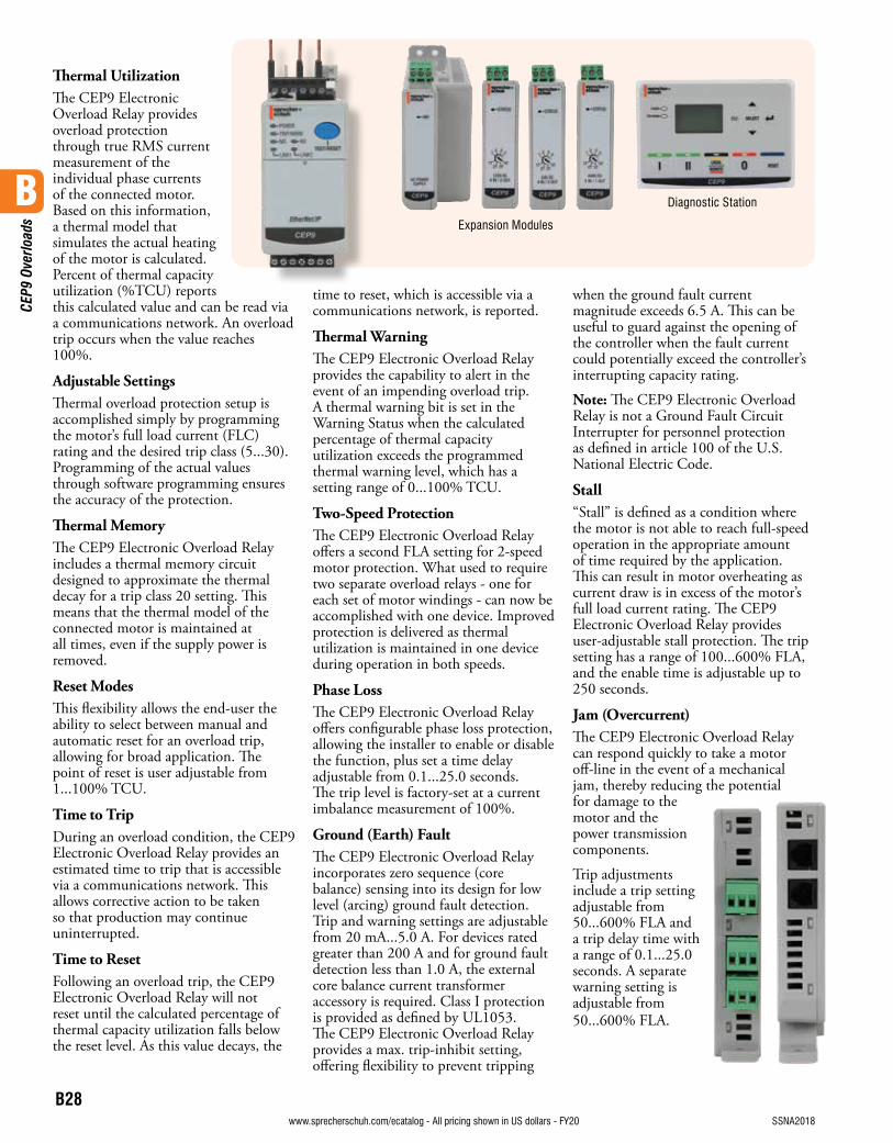
Thermal UtilizationThe CEP9 Electronic Overload Relay provides overload protection through true RMS current measurement of the individual phase currents of the connected motor. Based on this information, a thermal model that simulates the actual heating of the motor is calculated. Percent of thermal capacity utilization (%TCU) reports this calculated value and can be read via a communications network. An overload trip occurs when the value reaches 100%.
Adjustable SettingsThermal overload protection setup is accomplished simply by programming the motor’s full load current (FLC) rating and the desired trip class (5...30). Programming of the actual values through software programming ensures the accuracy of the protection.
Thermal MemoryThe CEP9 Electronic Overload Relay includes a thermal memory circuit designed to approximate the thermal decay for a trip class 20 setting. This means that the thermal model of the connected motor is maintained at all times, even if the supply power is removed.
Reset ModesThis flexibility allows the end-user the ability to select between manual and automatic reset for an overload trip, allowing for broad application. The point of reset is user adjustable from 1...100% TCU.
Time to TripDuring an overload condition, the CEP9 Electronic Overload Relay provides an estimated time to trip that is accessible via a communications network. This allows corrective action to be taken so that production may continue uninterrupted.
Time to ResetFollowing an overload trip, the CEP9 Electronic Overload Relay will not reset until the calculated percentage of thermal capacity utilization falls below the reset level. As this value decays, the
time to reset, which is accessible via a communications network, is reported.
Thermal WarningThe CEP9 Electronic Overload Relay provides the capability to alert in the event of an impending overload trip. A thermal warning bit is set in the Warning Status when the calculated percentage of thermal capacity utilization exceeds the programmed thermal warning level, which has a setting range of 0...100% TCU.
Two-Speed ProtectionThe CEP9 Electronic Overload Relay offers a second FLA setting for 2-speed motor protection. What used to require two separate overload relays - one for each set of motor windings - can now be accomplished with one device. Improved protection is delivered as thermal utilization is maintained in one device during operation in both speeds.
Phase LossThe CEP9 Electronic Overload Relay offers configurable phase loss protection, allowing the installer to enable or disable the function, plus set a time delay adjustable from 0.1...25.0 seconds. The trip level is factory-set at a current imbalance measurement of 100%.
Ground (Earth) FaultThe CEP9 Electronic Overload Relay incorporates zero sequence (core balance) sensing into its design for low level (arcing) ground fault detection. Trip and warning settings are adjustable from 20 mA...5.0 A. For devices rated greater than 200 A and for ground fault detection less than 1.0 A, the external core balance current transformer accessory is required. Class I protection is provided as defined by UL1053. The CEP9 Electronic Overload Relay provides a max. trip-inhibit setting, offering flexibility to prevent tripping
when the ground fault current magnitude exceeds 6.5 A. This can be useful to guard against the opening of the controller when the fault current could potentially exceed the controller’s interrupting capacity rating.
Note: The CEP9 Electronic Overload Relay is not a Ground Fault Circuit Interrupter for personnel protection as defined in article 100 of the U.S. National Electric Code.
Stall“Stall” is defined as a condition where the motor is not able to reach full-speed operation in the appropriate amount of time required by the application. This can result in motor overheating as current draw is in excess of the motor’s full load current rating. The CEP9 Electronic Overload Relay provides user-adjustable stall protection. The trip setting has a range of 100...600% FLA, and the enable time is adjustable up to 250 seconds.
Jam (Overcurrent)The CEP9 Electronic Overload Relay can respond quickly to take a motor off-line in the event of a mechanical jam, thereby reducing the potential for damage to the motor and the power transmission components.
Trip adjustments include a trip setting adjustable from 50...600% FLA and a trip delay time with a range of 0.1...25.0 seconds. A separate warning setting is adjustable from 50...600% FLA.
Expansion Modules
Diagnostic Station
B29visit www.sprecherschuh.com/ecatalog for pricing and the most up to date informationSSNA2018
B
CEP
9 Ov
erlo
ads
www.sprecherschuh.com/ecatalog - All pricing shown in US dollars - FY20
Underload (Undercurrent)A sudden drop in motor current can signal conditions such as:• Pump cavitation• Tool breakage• Belt breakage
For these instances, rapid fault detection can help minimize damage and aid in reducing production downtime.
Additionally, monitoring for an underload event can provide enhanced protection for motors that are coded by the medium handled (e.g., submersible pumps that pump water). Such motors can become overheated despite being underloaded. This can result from an absence or an insufficient amount of the medium (due to clogged filters, closed valves, etc.).
The CEP9 Electronic Overload Relay offers underload trip and warning settings adjustable from 10...100% FLA. The trip function also includes a trip delay time with a range of 0.1...25.0 seconds.
Current Imbalance (Asymmetry)The CEP9 Electronic Overload Relay offers current imbalance trip and warning settings adjustable from 10...100%. The trip function also includes a trip delay time with a range of 0.1...25.0 seconds.
Remote TripThe remote trip function allows an external device (e.g., a vibration sensor) to induce the CEP9 Electronic Overload Relay to trip. External device relay contacts are wired to the CEP9 Electronic Overload Relay discrete inputs. These discrete inputs are configurable with an option for assigning the remote trip function.
Current Monitoring FunctionsThe CEP9 Electronic Overload Relay allows the user to monitor the following operational data over a communications network:• Individual phase currents — in amperes• Individual phase currents — as a percentage of motor FLC• Average current — in amperes• Average current — as a percentage of motor FLC• Percentage of thermal capacity utilized• Current imbalance percentage• Ground fault current
Diagnostic FunctionsThe CEP9 Electronic Overload Relay allows the user to monitor the following diagnostic information over the Ethernet/IP network:
• Device status • Trip status • Warning status • Time to an overload trip • Time to reset after an
overload
• History of past five trips• History of positive warnings• Hours of operation• Number of starts• Trip snapshot trip
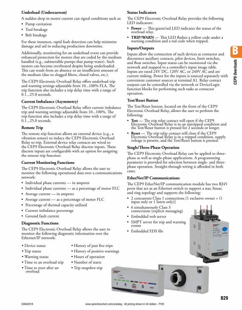
Status IndicatorsThe CEP9 Electronic Overload Relay provides the following LED indicators:• Power — This green/red LED indicates the status of the
overload relay.• TRIP/WARN — This LED flashes a yellow code under a
warning condition and a red code when tripped.
Inputs/OutputsInputs allow the connection of such devices as contactor and disconnect auxiliary contacts, pilot devices, limit switches, and float switches. Input status can be monitored via the network and mapped to a controller’s input image table. Inputs are rated 24V DC, 120V AC, or 240V AC and are current sinking. Power for the inputs is sourced separately with convenient customer sources at terminal A1. Relay contact outputs can be controlled via the network or DeviceLogix function blocks for performing such tasks as contactor operation.
Test/Reset ButtonThe Test/Reset button, located on the front of the CEP9 Electronic Overload Relay, allows the user to perform the following:• Test — The trip relay contact will open if the CEP9
Electronic Overload Relay is in an untripped condition and the Test/Reset button is pressed for 2 seconds or longer.
• Reset — The trip relay contact will close if the CEP9 Electronic Overload Relay is in a tripped condition, supply voltage is present, and the Test/Reset button is pressed.
Single/Three-Phase OperationThe CEP9 Electronic Overload Relay can be applied to three-phase as well as single-phase applications. A programming parameter is provided for selection between single- and three-phase operation. Straight-through wiring is afforded in both cases.
EtherNet/IP CommunicationsThe CEP9 EtherNet/IP communication module has two RJ45 ports that act as an Ethernet switch to support a star, linear, and ring topology and supports the following:• 2 concurrent Class 1 connections [1 exclusive owner + (1
input only or 1 listen only)]• 6 simultaneously Class 3
connections (explicit messaging)• Embedded web server• SMPT server for trip and warning
events• Embedded EDS file
B30visit www.sprecherschuh.com/ecatalog for pricing and the most up to date information SSNA2018
Discount Schedule B3
B
CEP
9 Ov
erlo
ads
www.sprecherschuh.com/ecatalog - All pricing shown in US dollars - FY20
➊ For Panel Mount option use KT7-45-AS Screw Adaptor. See page F16.➋ For Panel Mount option use CEP9-ESM-SA-100 Screw Adaptor. See page B33.
Electronic Overload RelaysSeries CEP9
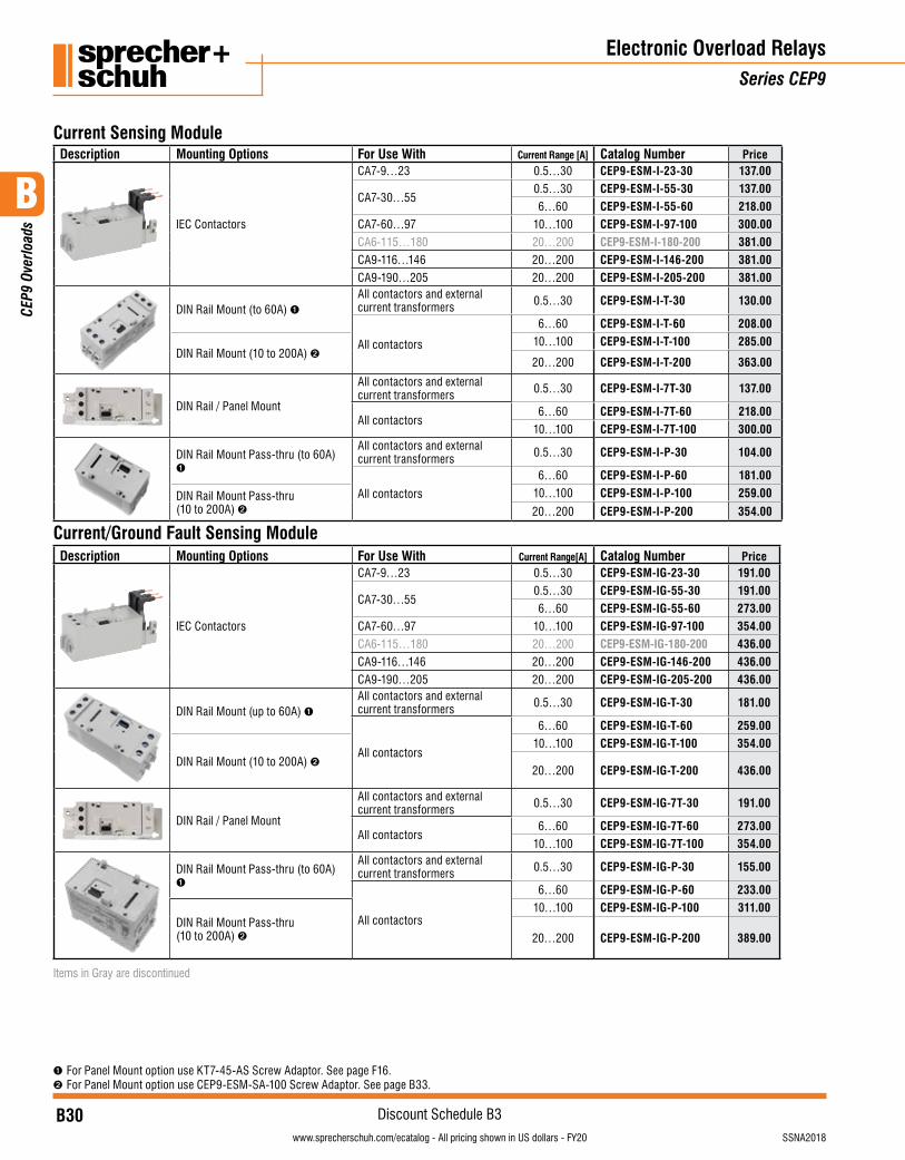
Current Sensing Module Description Mounting Options For Use With Current Range [A] Catalog Number Price
IEC Contactors
CA7-9…23 0.5…30 CEP9-ESM-I-23-30 137.00
CA7-30…550.5…30 CEP9-ESM-I-55-30 137.006…60 CEP9-ESM-I-55-60 218.00
CA7-60…97 10…100 CEP9-ESM-I-97-100 300.00CA6-115…180 20…200 CEP9-ESM-I-180-200 381.00CA9-116…146 20…200 CEP9-ESM-I-146-200 381.00CA9-190…205 20…200 CEP9-ESM-I-205-200 381.00
DIN Rail Mount (to 60A) ➊All contactors and external current transformers 0.5…30 CEP9-ESM-I-T-30 130.00
All contactors
6…60 CEP9-ESM-I-T-60 208.00
DIN Rail Mount (10 to 200A) ➋10…100 CEP9-ESM-I-T-100 285.00
20…200 CEP9-ESM-I-T-200 363.00
DIN Rail / Panel Mount
All contactors and external current transformers 0.5…30 CEP9-ESM-I-7T-30 137.00
All contactors6…60 CEP9-ESM-I-7T-60 218.00
10…100 CEP9-ESM-I-7T-100 300.00
DIN Rail Mount Pass-thru (to 60A) ➊
All contactors and external current transformers 0.5…30 CEP9-ESM-I-P-30 104.00
All contactors
6…60 CEP9-ESM-I-P-60 181.00
DIN Rail Mount Pass-thru (10 to 200A) ➋
10…100 CEP9-ESM-I-P-100 259.00
20…200 CEP9-ESM-I-P-200 354.00
Current/Ground Fault Sensing ModuleDescription Mounting Options For Use With Current Range[A] Catalog Number Price
IEC Contactors
CA7-9…23 0.5…30 CEP9-ESM-IG-23-30 191.00
CA7-30…550.5…30 CEP9-ESM-IG-55-30 191.006…60 CEP9-ESM-IG-55-60 273.00
CA7-60…97 10…100 CEP9-ESM-IG-97-100 354.00CA6-115…180 20…200 CEP9-ESM-IG-180-200 436.00CA9-116…146 20…200 CEP9-ESM-IG-146-200 436.00CA9-190…205 20…200 CEP9-ESM-IG-205-200 436.00
DIN Rail Mount (up to 60A) ➊All contactors and external current transformers 0.5…30 CEP9-ESM-IG-T-30 181.00
All contactors
6…60 CEP9-ESM-IG-T-60 259.00
DIN Rail Mount (10 to 200A) ➋
10…100 CEP9-ESM-IG-T-100 354.00
20…200 CEP9-ESM-IG-T-200 436.00
DIN Rail / Panel Mount
All contactors and external current transformers 0.5…30 CEP9-ESM-IG-7T-30 191.00
All contactors6…60 CEP9-ESM-IG-7T-60 273.00
10…100 CEP9-ESM-IG-7T-100 354.00
DIN Rail Mount Pass-thru (to 60A) ➊
All contactors and external current transformers 0.5…30 CEP9-ESM-IG-P-30 155.00
All contactors
6…60 CEP9-ESM-IG-P-60 233.00
DIN Rail Mount Pass-thru (10 to 200A) ➋
10…100 CEP9-ESM-IG-P-100 311.00
20…200 CEP9-ESM-IG-P-200 389.00
Items in Gray are discontinued
B31visit www.sprecherschuh.com/ecatalog for pricing and the most up to date informationSSNA2018
Discount Schedule B3
B
CEP
9 Ov
erlo
ads
www.sprecherschuh.com/ecatalog - All pricing shown in US dollars - FY20
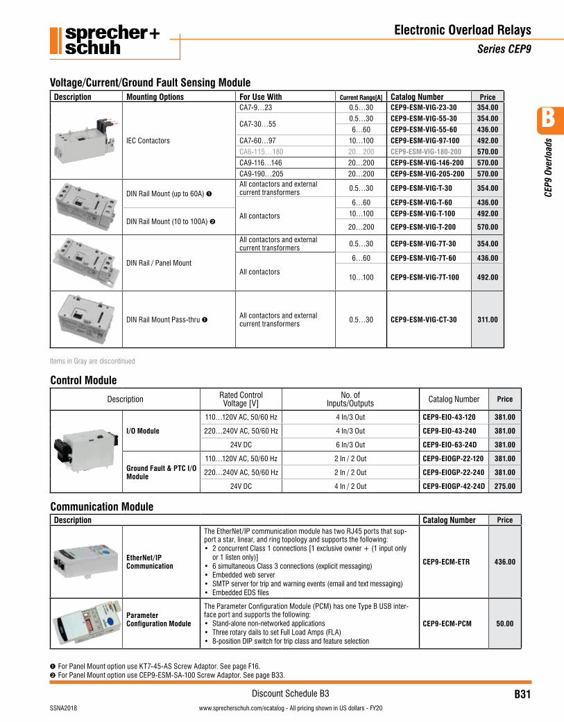
Voltage/Current/Ground Fault Sensing ModuleDescription Mounting Options For Use With Current Range[A] Catalog Number Price
IEC Contactors
CA7-9…23 0.5…30 CEP9-ESM-VIG-23-30 354.00
CA7-30…550.5…30 CEP9-ESM-VIG-55-30 354.006…60 CEP9-ESM-VIG-55-60 436.00
CA7-60…97 10…100 CEP9-ESM-VIG-97-100 492.00CA6-115…180 20…200 CEP9-ESM-VIG-180-200 570.00CA9-116…146 20…200 CEP9-ESM-VIG-146-200 570.00CA9-190…205 20…200 CEP9-ESM-VIG-205-200 570.00
DIN Rail Mount (up to 60A) ➊All contactors and external current transformers 0.5…30 CEP9-ESM-VIG-T-30 354.00
All contactors
6…60 CEP9-ESM-VIG-T-60 436.00
DIN Rail Mount (10 to 100A) ➋10…100 CEP9-ESM-VIG-T-100 492.00
20…200 CEP9-ESM-VIG-T-200 570.00
DIN Rail / Panel Mount
All contactors and external current transformers 0.5…30 CEP9-ESM-VIG-7T-30 354.00
All contactors
6…60 CEP9-ESM-VIG-7T-60 436.00
10…100 CEP9-ESM-VIG-7T-100 492.00
DIN Rail Mount Pass-thru ➊ All contactors and external current transformers 0.5…30 CEP9-ESM-VIG-CT-30 311.00
Items in Gray are discontinued
Control Module
Description Rated Control Voltage [V]
No. of Inputs/Outputs Catalog Number Price
I/O Module
110…120V AC, 50/60 Hz 4 In/3 Out CEP9-EIO-43-120 381.00
220…240V AC, 50/60 Hz 4 In/3 Out CEP9-EIO-43-240 381.00
24V DC 6 In/3 Out CEP9-EIO-63-24D 381.00
Ground Fault & PTC I/O Module
110…120V AC, 50/60 Hz 2 In / 2 Out CEP9-EIOGP-22-120 381.00
220…240V AC, 50/60 Hz 2 In / 2 Out CEP9-EIOGP-22-240 381.00
24V DC 4 In / 2 Out CEP9-EIOGP-42-24D 275.00
Communication ModuleDescription Catalog Number Price
EtherNet/IP Communication
The EtherNet/IP communication module has two RJ45 ports that sup-port a star, linear, and ring topology and supports the following: • 2 concurrent Class 1 connections [1 exclusive owner + (1 input only
or 1 listen only)]• 6 simultaneous Class 3 connections (explicit messaging)• Embedded web server• SMTP server for trip and warning events (email and text messaging)• Embedded EDS files
CEP9-ECM-ETR 436.00
Parameter Configuration Module
The Parameter Configuration Module (PCM) has one Type B USB inter-face port and supports the following:• Stand-alone non-networked applications• Three rotary dails to set Full Load Amps (FLA)• 8-position DIP switch for trip class and feature selection
CEP9-ECM-PCM 50.00
Electronic Overload RelaysSeries CEP9
➊ For Panel Mount option use KT7-45-AS Screw Adaptor. See page F16.➋ For Panel Mount option use CEP9-ESM-SA-100 Screw Adaptor. See page B33.
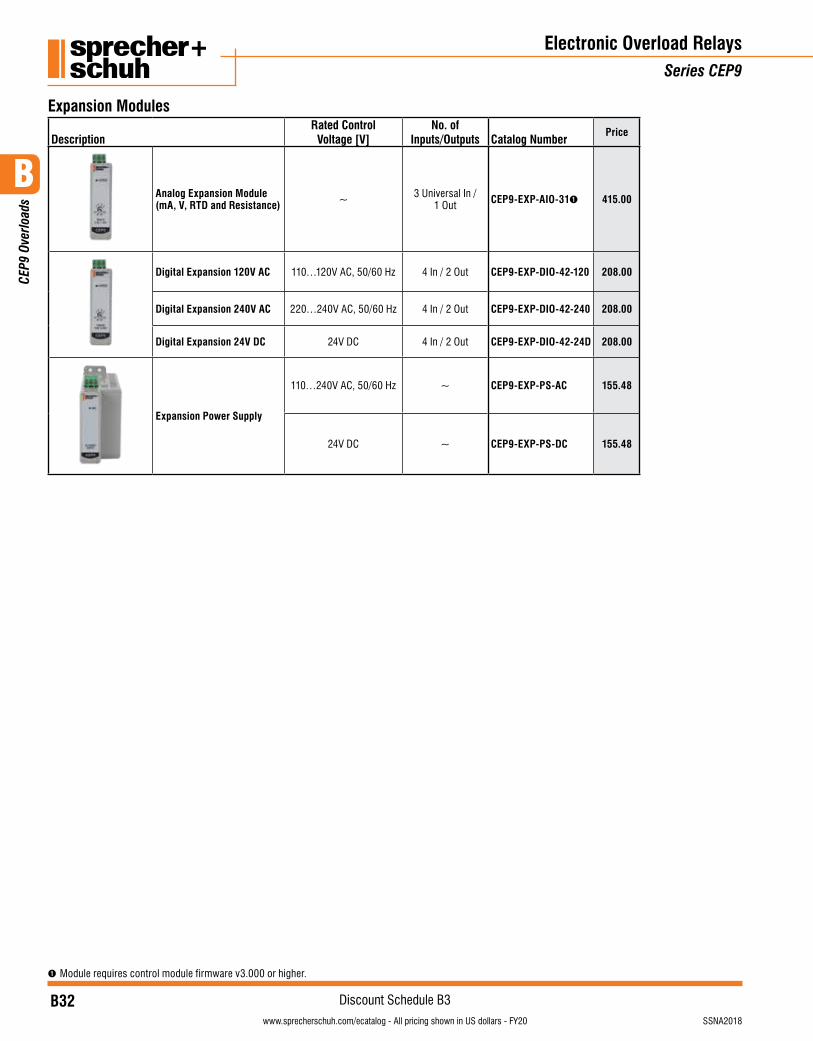
B32visit www.sprecherschuh.com/ecatalog for pricing and the most up to date information SSNA2018
Discount Schedule B3
B
CEP
9 Ov
erlo
ads
www.sprecherschuh.com/ecatalog - All pricing shown in US dollars - FY20
➊ Module requires control module firmware v3.000 or higher.
Electronic Overload RelaysSeries CEP9
Expansion Modules
DescriptionRated Control
Voltage [V]No. of
Inputs/Outputs Catalog NumberPrice
Analog Expansion Module (mA, V, RTD and Resistance) ~ 3 Universal In /
1 Out CEP9-EXP-AIO-31➊ 415.00
Digital Expansion 120V AC 110…120V AC, 50/60 Hz 4 In / 2 Out CEP9-EXP-DIO-42-120 208.00
Digital Expansion 240V AC 220…240V AC, 50/60 Hz 4 In / 2 Out CEP9-EXP-DIO-42-240 208.00
Digital Expansion 24V DC 24V DC 4 In / 2 Out CEP9-EXP-DIO-42-24D 208.00
Expansion Power Supply
110…240V AC, 50/60 Hz ~ CEP9-EXP-PS-AC 155.48
24V DC ~ CEP9-EXP-PS-DC 155.48
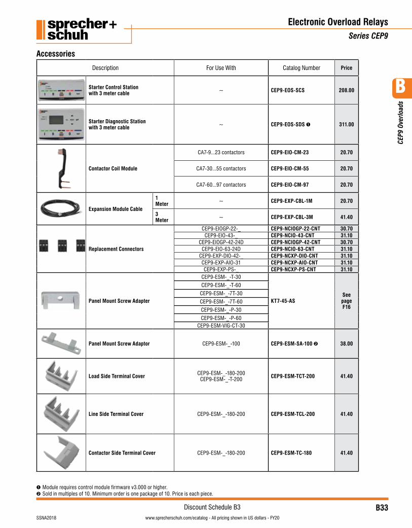
B33visit www.sprecherschuh.com/ecatalog for pricing and the most up to date informationSSNA2018
Discount Schedule B3
B
CEP
9 Ov
erlo
ads
www.sprecherschuh.com/ecatalog - All pricing shown in US dollars - FY20
Electronic Overload RelaysSeries CEP9
Accessories
Description For Use With Catalog Number Price
Starter Control Station with 3 meter cable ~ CEP9-EOS-SCS 208.00
Starter Diagnostic Station with 3 meter cable ~ CEP9-EOS-SDS ➊ 311.00
Contactor Coil Module
CA7-9...23 contactors CEP9-EIO-CM-23 20.70
CA7-30...55 contactors CEP9-EIO-CM-55 20.70
CA7-60...97 contactors CEP9-EIO-CM-97 20.70
Expansion Module Cable
1 Meter ~ CEP9-EXP-CBL-1M 20.70
3 Meter ~ CEP9-EXP-CBL-3M 41.40
Replacement Connectors
CEP9-EIOGP-22-_ CEP9-NCIOGP-22-CNT 30.70CEP9-EIO-43-_ CEP9-NCIO-43-CNT 31.10
CEP9-EIOGP-42-24D CEP9-NCIOGP-42-CNT 30.70CEP9-EIO-63-24D CEP9-NCIO-63-CNT 31.10
CEP9-EXP-DIO-42-_ CEP9-NCXP-DIO-CNT 31.10CEP9-EXP-AIO-31 CEP9-NCXP-AIO-CNT 31.10CEP9-EXP-PS-_ CEP9-NCXP-PS-CNT 31.10
Panel Mount Screw Adapter
CEP9-ESM-_-T-30
KT7-45-ASSee page F16
CEP9-ESM-_-T-60
CEP9-ESM-_-7T-30
CEP9-ESM-_-7T-60
CEP9-ESM-_-P-30
CEP9-ESM-_-P-60CEP9-ESM-VIG-CT-30
Panel Mount Screw Adaptor CEP9-ESM-_-100 CEP9-ESM-SA-100 ➋ 38.00
Load Side Terminal Cover CEP9-ESM-_-180-200CEP9-ESM-_-T-200 CEP9-ESM-TCT-200 41.40
Line Side Terminal Cover CEP9-ESM-_-180-200 CEP9-ESM-TCL-200 41.40
Contactor Side Terminal Cover CEP9-ESM-_-180-200 CEP9-ESM-TC-180 41.40
➊ Module requires control module firmware v3.000 or higher. ➋ Sold in multiples of 10. Minimum order is one package of 10. Price is each piece.
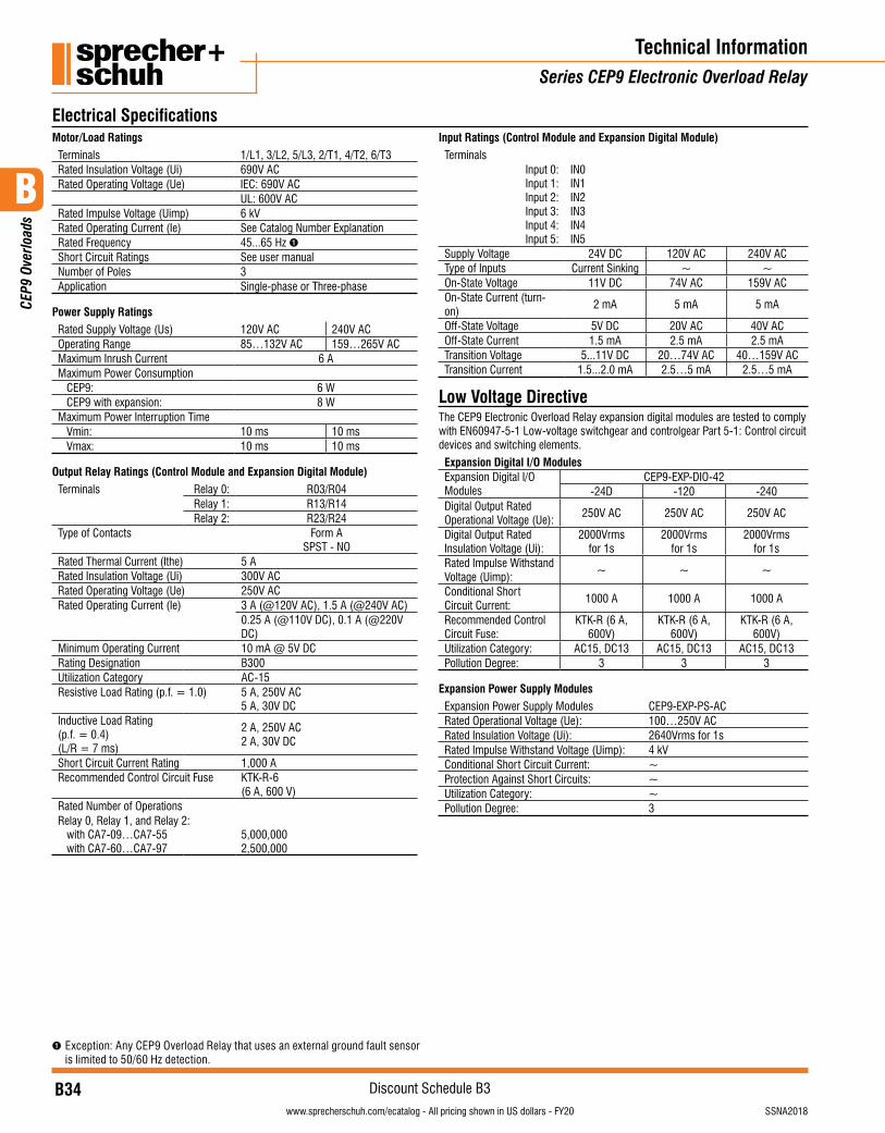
B34visit www.sprecherschuh.com/ecatalog for pricing and the most up to date information SSNA2018
Discount Schedule B3
B
CEP
9 Ov
erlo
ads
www.sprecherschuh.com/ecatalog - All pricing shown in US dollars - FY20
Electrical SpecificationsMotor/Load Ratings
Terminals 1/L1, 3/L2, 5/L3, 2/T1, 4/T2, 6/T3Rated Insulation Voltage (Ui) 690V ACRated Operating Voltage (Ue) IEC: 690V AC
UL: 600V ACRated Impulse Voltage (Uimp) 6 kVRated Operating Current (Ie) See Catalog Number ExplanationRated Frequency 45...65 Hz ➊Short Circuit Ratings See user manualNumber of Poles 3Application Single-phase or Three-phase
Power Supply Ratings
Rated Supply Voltage (Us) 120V AC 240V ACOperating Range 85…132V AC 159…265V ACMaximum Inrush Current 6 AMaximum Power Consumption
CEP9: 6 WCEP9 with expansion: 8 W
Maximum Power Interruption TimeVmin: 10 ms 10 msVmax: 10 ms 10 ms
Output Relay Ratings (Control Module and Expansion Digital Module)
Terminals Relay 0: R03/R04Relay 1: R13/R14Relay 2: R23/R24
Type of Contacts Form ASPST - NO
Rated Thermal Current (Ithe) 5 ARated Insulation Voltage (Ui) 300V ACRated Operating Voltage (Ue) 250V ACRated Operating Current (Ie) 3 A (@120V AC), 1.5 A (@240V AC)
0.25 A (@110V DC), 0.1 A (@220V DC)
Minimum Operating Current 10 mA @ 5V DCRating Designation B300Utilization Category AC-15Resistive Load Rating (p.f. = 1.0) 5 A, 250V AC
5 A, 30V DCInductive Load Rating(p.f. = 0.4)(L/R = 7 ms)
2 A, 250V AC2 A, 30V DC
Short Circuit Current Rating 1,000 ARecommended Control Circuit Fuse KTK-R-6
(6 A, 600 V)Rated Number of Operations Relay 0, Relay 1, and Relay 2:
with CA7-09…CA7-55with CA7-60…CA7-97
5,000,000 2,500,000
➊ Exception: Any CEP9 Overload Relay that uses an external ground fault sensor is limited to 50/60 Hz detection.
Input Ratings (Control Module and Expansion Digital Module)
TerminalsInput 0:Input 1:Input 2:Input 3:Input 4:Input 5:
IN0IN1IN2IN3IN4IN5
Supply Voltage 24V DC 120V AC 240V ACType of Inputs Current Sinking ~ ~On-State Voltage 11V DC 74V AC 159V ACOn-State Current (turn-on)
2 mA 5 mA 5 mA
Off-State Voltage 5V DC 20V AC 40V ACOff-State Current 1.5 mA 2.5 mA 2.5 mATransition Voltage 5...11V DC 20…74V AC 40…159V ACTransition Current 1.5...2.0 mA 2.5…5 mA 2.5…5 mA
Low Voltage DirectiveThe CEP9 Electronic Overload Relay expansion digital modules are tested to comply with EN60947-5-1 Low-voltage switchgear and controlgear Part 5-1: Control circuit devices and switching elements.
Expansion Digital I/O ModulesExpansion Digital I/O Modules
CEP9-EXP-DIO-42-24D -120 -240
Digital Output Rated Operational Voltage (Ue):
250V AC 250V AC 250V AC
Digital Output Rated Insulation Voltage (Ui):
2000Vrms for 1s
2000Vrms for 1s
2000Vrms for 1s
Rated Impulse Withstand Voltage (Uimp):
~ ~ ~
Conditional Short Circuit Current:
1000 A 1000 A 1000 A
Recommended Control Circuit Fuse:
KTK-R (6 A, 600V)
KTK-R (6 A, 600V)
KTK-R (6 A, 600V)
Utilization Category: AC15, DC13 AC15, DC13 AC15, DC13Pollution Degree: 3 3 3
Expansion Power Supply Modules
Expansion Power Supply Modules CEP9-EXP-PS-ACRated Operational Voltage (Ue): 100…250V ACRated Insulation Voltage (Ui): 2640Vrms for 1sRated Impulse Withstand Voltage (Uimp): 4 kVConditional Short Circuit Current: ~Protection Against Short Circuits: ~Utilization Category: ~Pollution Degree: 3
Technical InformationSeries CEP9 Electronic Overload Relay
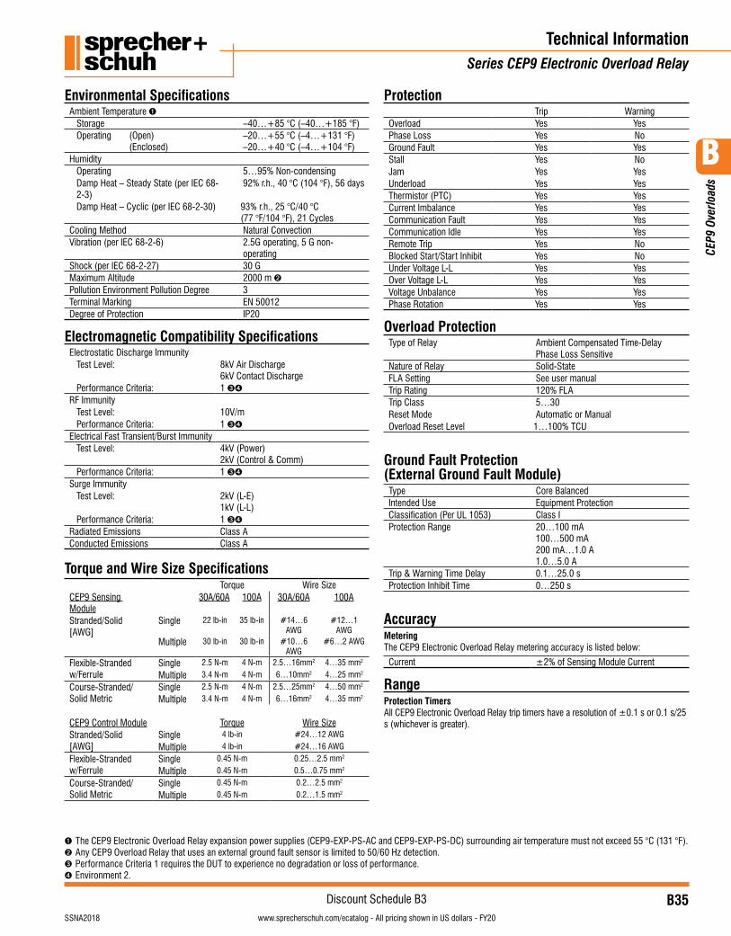
B35visit www.sprecherschuh.com/ecatalog for pricing and the most up to date informationSSNA2018
Discount Schedule B3
B
CEP
9 Ov
erlo
ads
www.sprecherschuh.com/ecatalog - All pricing shown in US dollars - FY20
Technical InformationSeries CEP9 Electronic Overload Relay
Environmental SpecificationsAmbient Temperature ➊
Storage –40…+85 °C (–40…+185 °F)Operating (Open) (Enclosed)
–20…+55 °C (–4…+131 °F)–20…+40 °C (–4…+104 °F)
HumidityOperating 5…95% Non-condensingDamp Heat – Steady State (per IEC 68-2-3)
92% r.h., 40 °C (104 °F), 56 days
Damp Heat – Cyclic (per IEC 68-2-30) 93% r.h., 25 °C/40 °C (77 °F/104 °F), 21 Cycles
Cooling Method Natural ConvectionVibration (per IEC 68-2-6) 2.5G operating, 5 G non-
operatingShock (per IEC 68-2-27) 30 GMaximum Altitude 2000 m ➋Pollution Environment Pollution Degree 3Terminal Marking EN 50012Degree of Protection IP20
Electromagnetic Compatibility SpecificationsElectrostatic Discharge Immunity
Test Level: 8kV Air Discharge6kV Contact Discharge
Performance Criteria: 1 ➌➍
RF ImmunityTest Level: 10V/mPerformance Criteria: 1 ➌➍
Electrical Fast Transient/Burst ImmunityTest Level: 4kV (Power)
2kV (Control & Comm)Performance Criteria: 1 ➌➍
Surge ImmunityTest Level: 2kV (L-E)
1kV (L-L)Performance Criteria: 1 ➌➍
Radiated Emissions Class AConducted Emissions Class A
Torque and Wire Size Specifications Torque Wire Size
CEP9 Sensing Module
30A/60A 100A 30A/60A 100A
Stranded/Solid [AWG]
Single 22 lb-in 35 lb-in #14…6 AWG
#12…1 AWG
Multiple 30 lb-in 30 lb-in #10…6 AWG
#6…2 AWG
Flexible-Stranded w/Ferrule
Single 2.5 N-m 4 N-m 2.5…16mm2 4…35 mm2
Multiple 3.4 N-m 4 N-m 6…10mm2 4…25 mm2
Course-Stranded/ Solid Metric
Single 2.5 N-m 4 N-m 2.5…25mm2 4…50 mm2
Multiple 3.4 N-m 4 N-m 6…16mm2 4…35 mm2
CEP9 Control Module Torque Wire SizeStranded/Solid [AWG]
Single 4 lb-in #24…12 AWG
Multiple 4 lb-in #24…16 AWG
Flexible-Stranded w/Ferrule
Single 0.45 N-m 0.25…2.5 mm2
Multiple 0.45 N-m 0.5…0.75 mm2
Course-Stranded/ Solid Metric
Single 0.45 N-m 0.2…2.5 mm2
Multiple 0.45 N-m 0.2…1.5 mm2
➊ The CEP9 Electronic Overload Relay expansion power supplies (CEP9-EXP-PS-AC and CEP9-EXP-PS-DC) surrounding air temperature must not exceed 55 °C (131 °F).➋ Any CEP9 Overload Relay that uses an external ground fault sensor is limited to 50/60 Hz detection.➌ Performance Criteria 1 requires the DUT to experience no degradation or loss of performance.➍ Environment 2.
ProtectionTrip Warning
Overload Yes YesPhase Loss Yes NoGround Fault Yes YesStall Yes NoJam Yes YesUnderload Yes YesThermistor (PTC) Yes YesCurrent Imbalance Yes YesCommunication Fault Yes YesCommunication Idle Yes YesRemote Trip Yes NoBlocked Start/Start Inhibit Yes NoUnder Voltage L-L Yes YesOver Voltage L-L Yes YesVoltage Unbalance Yes YesPhase Rotation Yes Yes
Overload ProtectionType of Relay Ambient Compensated Time-Delay
Phase Loss SensitiveNature of Relay Solid-StateFLA Setting See user manualTrip Rating 120% FLATrip Class 5…30Reset Mode Automatic or ManualOverload Reset Level 1…100% TCU
Ground Fault Protection (External Ground Fault Module)
Type Core BalancedIntended Use Equipment ProtectionClassification (Per UL 1053) Class IProtection Range 20…100 mA
100…500 mA200 mA…1.0 A1.0…5.0 A
Trip & Warning Time Delay 0.1…25.0 sProtection Inhibit Time 0…250 s
AccuracyMeteringThe CEP9 Electronic Overload Relay metering accuracy is listed below:
Current ±2% of Sensing Module Current
RangeProtection TimersAll CEP9 Electronic Overload Relay trip timers have a resolution of ±0.1 s or 0.1 s/25 s (whichever is greater).
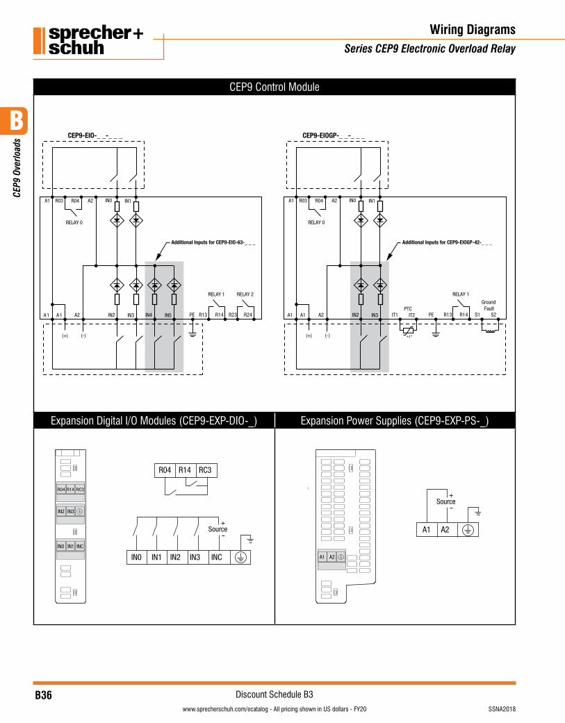
B36visit www.sprecherschuh.com/ecatalog for pricing and the most up to date information SSNA2018
Discount Schedule B3
B
CEP
9 Ov
erlo
ads
www.sprecherschuh.com/ecatalog - All pricing shown in US dollars - FY20
Wiring DiagramsSeries CEP9 Electronic Overload Relay
CEP9 Control Module
32R 42R
RELAY 2RELAY 1
31R 41RIN3IN2
Additional Inputs for CEP9-EIO-63-_ _ _
IN0 IN1
A2 PE1A 1A
A1 R03 R04 A2
IN5IN4
(+) (-)
RELAY 0
1S 2S
RELAY 1
31R 41RIN3IN2
IN0 IN1
A2A1A1
A1 R03 R04 A2
IT2IT1
(+) (-)
RELAY 0
CEP9-EIOGP-_ _-_ _ _CEP9-EIO-_ _-_ _ _
PE
Ground Fault PTC
Additional Inputs for CEP9-EIOGP-42-_ _ _
+t
Expansion Digital I/O Modules (CEP9-EXP-DIO-_) Expansion Power Supplies (CEP9-EXP-PS-_)
R04 R14 RC3
IN0 INCIN1 IN2 IN3
Source+
-IN0 IN1 INC
IN2 IN3
RS2R04 R14 RC3
A1 A2
Source+
-
A1 A2
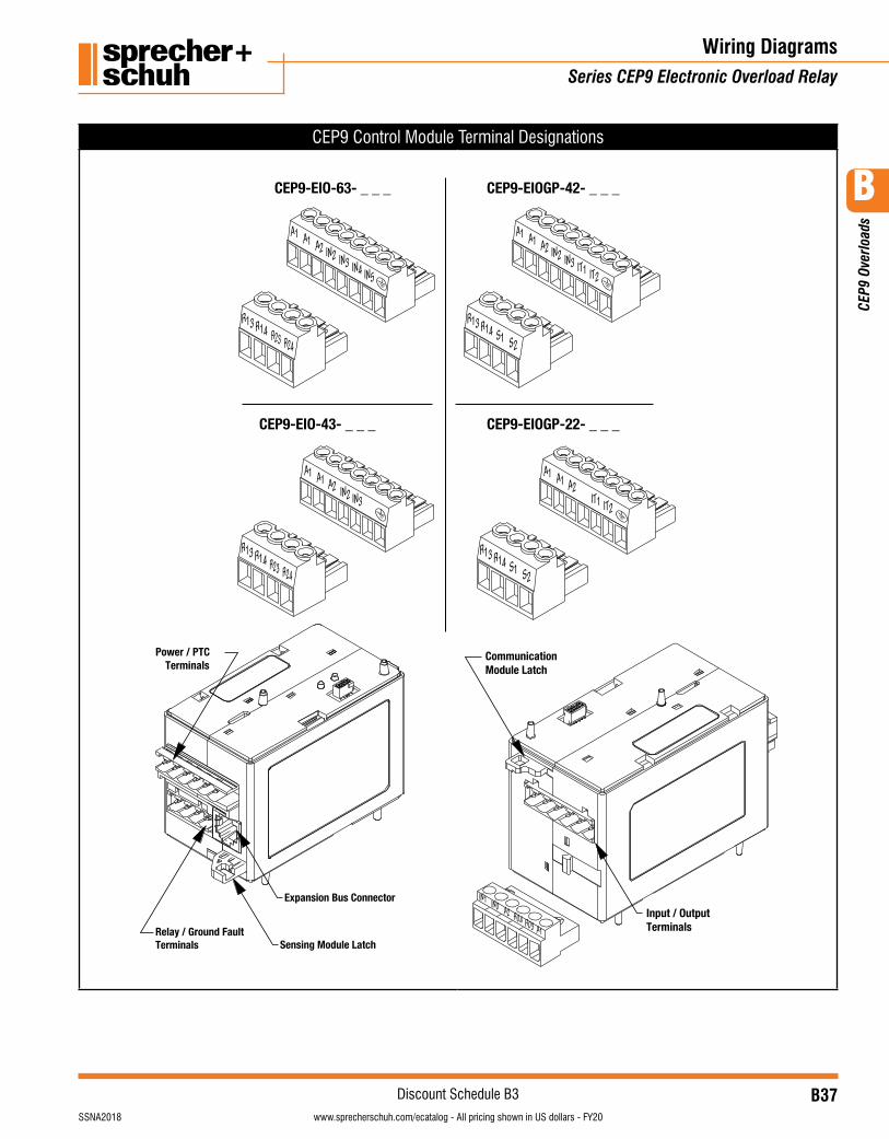
B37visit www.sprecherschuh.com/ecatalog for pricing and the most up to date informationSSNA2018
Discount Schedule B3
B
CEP
9 Ov
erlo
ads
www.sprecherschuh.com/ecatalog - All pricing shown in US dollars - FY20
CEP9 Control Module Terminal Designations
CEP9-EIOGP-42- _ _ _
CEP9-EIOGP-22- _ _ _
Sensing Module Latch
Power / PTCTerminals
Expansion Bus Connector
Relay / Ground FaultTerminals
R13 R14 S1 S2
A1 A1 A2 IN2 IN3 IT1 IT2
CEP9-EIO-63- _ _ _
CEP9-EIO-43- _ _ _
R13 R14 R23 R24
A1 A1 A2 IN2 IN3 IN4 IN5
R13 R14 R23 R24
A1 A1 A2 IN2 IN3
Input / OutputTerminals
CommunicationModule Latch
IN1 IN0 A2
A1
R04 R03
R13 R14 S1 S2
A1 A1 A2IT1 IT2
Wiring DiagramsSeries CEP9 Electronic Overload Relay
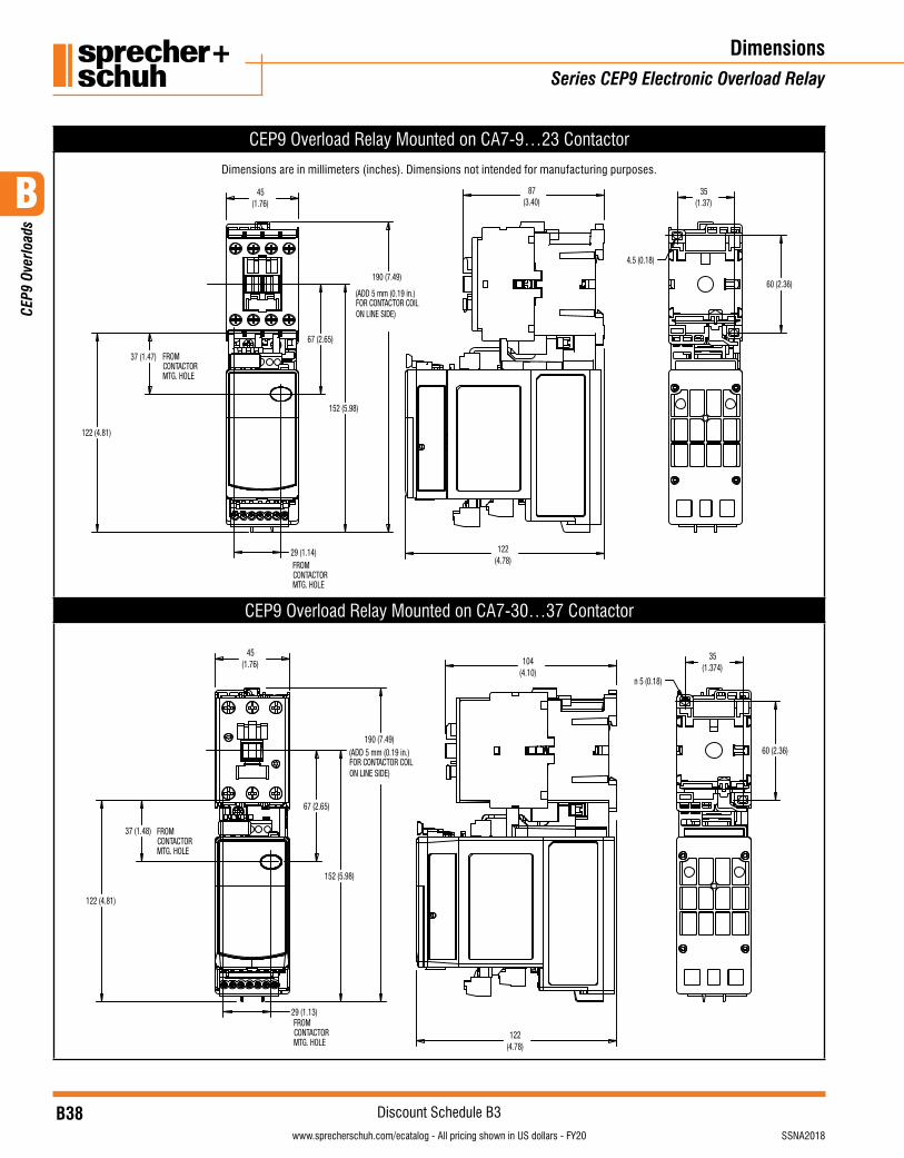
B38visit www.sprecherschuh.com/ecatalog for pricing and the most up to date information SSNA2018
Discount Schedule B3
B
CEP
9 Ov
erlo
ads
www.sprecherschuh.com/ecatalog - All pricing shown in US dollars - FY20
CEP9 Overload Relay Mounted on CA7-9…23 Contactor
Dimensions are in millimeters (inches). Dimensions not intended for manufacturing purposes.
45(1.76)
87(3.40)
60 (2.36)
35(1.37)
4.5 (0.18)
190 (7.49)
37 (1.47)
122 (4.81)
29 (1.14) 122(4.78)
152 (5.98)
67 (2.65)
FROMCONTACTORMTG. HOLE
FROMCONTACTORMTG. HOLE
(ADD 5 mm (0.19 in.) FOR CONTACTOR COILON LINE SIDE)
CEP9 Overload Relay Mounted on CA7-30…37 Contactor
37 (1.48)
122 (4.81)
29 (1.13)
190 (7.49)
67 (2.65)
152 (5.98)
45(1.76)
122(4.78)
104(4.10)
35(1.374)
60 (2.36)
n 5 (0.18)
(ADD 5 mm (0.19 in.)FOR CONTACTOR COILON LINE SIDE)
FROMCONTACTORMTG. HOLE
FROMCONTACTORMTG. HOLE
DimensionsSeries CEP9 Electronic Overload Relay
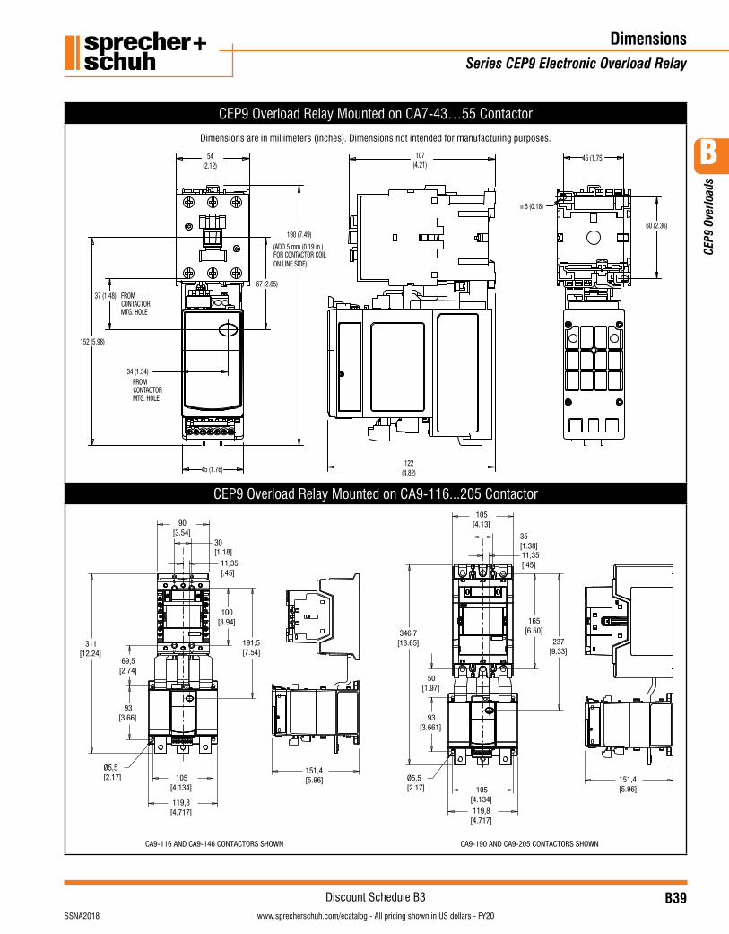
B39visit www.sprecherschuh.com/ecatalog for pricing and the most up to date informationSSNA2018
Discount Schedule B3
B
CEP
9 Ov
erlo
ads
www.sprecherschuh.com/ecatalog - All pricing shown in US dollars - FY20
CEP9 Overload Relay Mounted on CA7-43…55 Contactor
Dimensions are in millimeters (inches). Dimensions not intended for manufacturing purposes.
54(2.12)
45 (1.76)
190 (7.49)
107(4.21)
60 (2.36)
45 (1.75)
n 5 (0.18)
37 (1.48)
34 (1.34)
122(4.82)
152 (5.98)
67 (2.65)
FROMCONTACTORMTG. HOLE
FROMCONTACTORMTG. HOLE
(ADD 5 mm (0.19 in.)FOR CONTACTOR COILON LINE SIDE)
CEP9 Overload Relay Mounted on CA9-116...205 Contactor
30[1.18]
191,5[7.54]
11,35[.45]
90[3.54]
100[3.94]
69,5[2.74]
93[3.66]
311[12.24]
105[4.134]
119,8[4.717]
Ø5,5[2.17]
151,4[5.96]
35[1.38]11,35[.45]
105[4.13]
165[6.50]
237[9.33]
50[1.97]
93[3.661]
105[4.134]119,8
[4.717]
346,7[13.65]
151,4[5.96]
Ø5,5[2.17]
CA9-116 AND CA9-146 CONTACTORS SHOWN CA9-190 AND CA9-205 CONTACTORS SHOWN
DimensionsSeries CEP9 Electronic Overload Relay
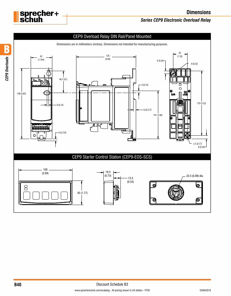
B40visit www.sprecherschuh.com/ecatalog for pricing and the most up to date information SSNA2018
Discount Schedule B3
B
CEP
9 Ov
erlo
ads
www.sprecherschuh.com/ecatalog - All pricing shown in US dollars - FY20
CEP9 Overload Relay DIN Rail/Panel Mounted
Dimensions are in millimeters (inches). Dimensions not intended for manufacturing purposes.
45(1.764)
135 (5.32)
30(1.18)
n 5 (0.17)
6 (0.24)
6 (0.217)
9 (0.33)
148 (5.83)
4 (0.154)
46 (1.81)
4 (0.14)
126(4.94)
101 (3.96)
4 (0.16)
8 (0.30)
CEP9 Starter Control Station (CEP9-EOS-SCS)
100(3.94)
45 (1.77)
18.5(0.73)
13.5(0.53)
22.5 (0.89) dia.
DimensionsSeries CEP9 Electronic Overload Relay
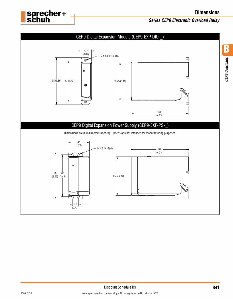
B41visit www.sprecherschuh.com/ecatalog for pricing and the most up to date informationSSNA2018
Discount Schedule B3
B
CEP
9 Ov
erlo
ads
www.sprecherschuh.com/ecatalog - All pricing shown in US dollars - FY20
CEP9 Digital Expansion Module (CEP9-EXP-DIO-_)
2 x 4.5 (0.18) dia.
22.5(0.89)
80.75 (3.18)
120(4.73)
98 (3.86) 87 (3.43)
CEP9 Digital Expansion Power Supply (CEP9-EXP-PS-_)
Dimensions are in millimeters (inches). Dimensions not intended for manufacturing purposes.
120(4.73)
80.75 (3.18)
45(1.77)
4x 4.5 (0.18) dia
98(3.86)
87(3.43)
12(0.47)
DimensionsSeries CEP9 Electronic Overload Relay
B42visit www.sprecherschuh.com/ecatalog for pricing and the most up to date information SSNA2018
Discount Schedule B3
B
CEP
9 Ov
erlo
ads
www.sprecherschuh.com/ecatalog - All pricing shown in US dollars - FY20
DimensionsSeries CEP9 Electronic Overload Relay
Notes
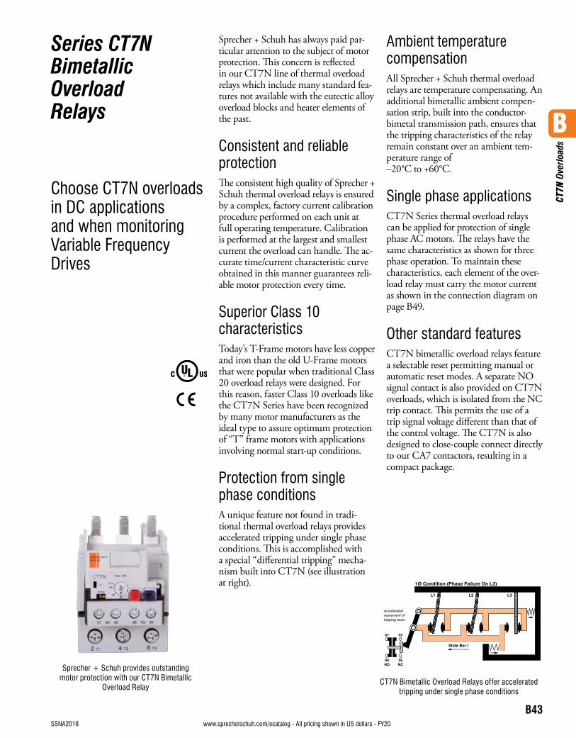
B43visit www.sprecherschuh.com/ecatalog for pricing and the most up to date informationSSNA2018
B
CT7
N O
verlo
ads
www.sprecherschuh.com/ecatalog - All pricing shown in US dollars - FY20
Series CT7N Bimetallic Overload Relays
Choose CT7N overloads in DC applications and when monitoring Variable Frequency Drives
Sprecher + Schuh has always paid par-ticular attention to the subject of motor protection. This concern is reflected in our CT7N line of thermal overload relays which include many standard fea-tures not available with the eutectic alloy overload blocks and heater elements of the past.
Consistent and reliable protectionThe consistent high quality of Sprecher + Schuh thermal overload relays is ensured by a complex, factory current calibration procedure performed on each unit at full operating temperature. Calibration is performed at the largest and smallest current the overload can handle. The ac-curate time/current characteristic curve obtained in this manner guarantees reli-able motor protection every time.
Superior Class 10 characteristicsToday’s T-Frame motors have less copper and iron than the old U-Frame motors that were popular when traditional Class 20 overload relays were designed. For this reason, faster Class 10 overloads like the CT7N Series have been recognized by many motor manufacturers as the ideal type to assure optimum protection of “T” frame motors with applications involving normal start-up conditions.
Protection from single phase conditionsA unique feature not found in tradi-tional thermal overload relays provides accelerated tripping under single phase conditions. This is accomplished with a special “differential tripping” mecha-nism built into CT7N (see illustration at right).
Ambient temperature compensationAll Sprecher + Schuh thermal overload relays are temperature compensating. An additional bimetallic ambient compen-sation strip, built into the conductor-bimetal transmission path, ensures that the tripping characteristics of the relay remain constant over an ambient tem-perature range of –20°C to +60°C.
Single phase applicationsCT7N Series thermal overload relays can be applied for protection of single phase AC motors. The relays have the same characteristics as shown for three phase operation. To maintain these characteristics, each element of the over-load relay must carry the motor current as shown in the connection diagram on page B49.
Other standard featuresCT7N bimetallic overload relays feature a selectable reset permitting manual or automatic reset modes. A separate NO signal contact is also provided on CT7N overloads, which is isolated from the NC trip contact. This permits the use of a trip signal voltage different than that of the control voltage. The CT7N is also designed to close-couple connect directly to our CA7 contactors, resulting in a compact package.
Sprecher + Schuh provides outstanding motor protection with our CT7N Bimetallic
Overload RelayCT7N Bimetallic Overload Relays offer accelerated
tripping under single phase conditions
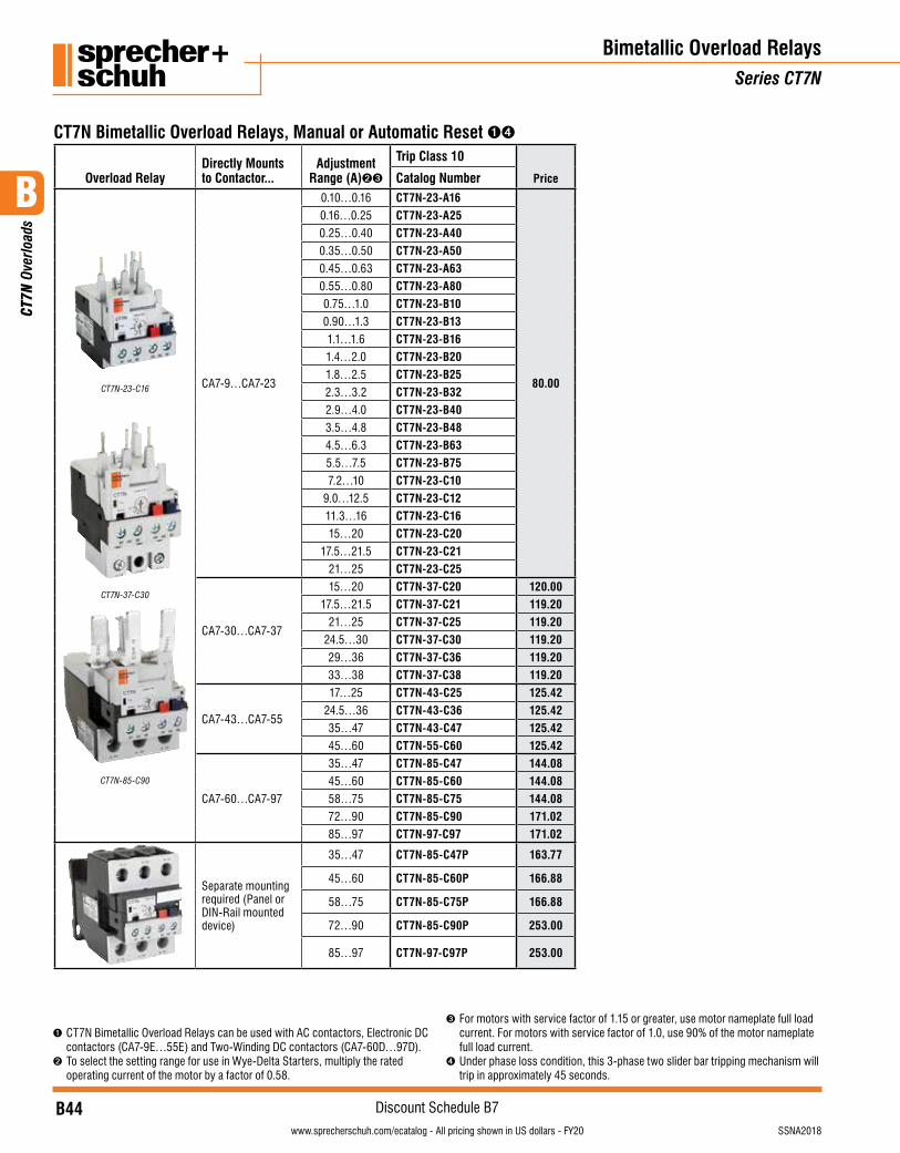
B44visit www.sprecherschuh.com/ecatalog for pricing and the most up to date information SSNA2018
Discount Schedule B7
B
CT7
N O
verlo
ads
www.sprecherschuh.com/ecatalog - All pricing shown in US dollars - FY20
CT7N Bimetallic Overload Relays, Manual or Automatic Reset ➊➍
Overload RelayDirectly Mounts to Contactor...
Adjustment Range (A)➋➌
Trip Class 10
Catalog Number Price
CT7N-23-C16
CT7N-37-C30
CT7N-85-C90
CA7-9…CA7-23
0.10…0.16 CT7N-23-A16
80.00
0.16…0.25 CT7N-23-A250.25…0.40 CT7N-23-A400.35…0.50 CT7N-23-A500.45…0.63 CT7N-23-A630.55…0.80 CT7N-23-A800.75…1.0 CT7N-23-B100.90…1.3 CT7N-23-B131.1…1.6 CT7N-23-B161.4…2.0 CT7N-23-B201.8…2.5 CT7N-23-B252.3…3.2 CT7N-23-B322.9…4.0 CT7N-23-B403.5…4.8 CT7N-23-B484.5…6.3 CT7N-23-B635.5…7.5 CT7N-23-B757.2…10 CT7N-23-C10
9.0…12.5 CT7N-23-C1211.3…16 CT7N-23-C1615…20 CT7N-23-C20
17.5…21.5 CT7N-23-C2121…25 CT7N-23-C25
CA7-30…CA7-37
15…20 CT7N-37-C20 120.0017.5…21.5 CT7N-37-C21 119.20
21…25 CT7N-37-C25 119.2024.5…30 CT7N-37-C30 119.2029…36 CT7N-37-C36 119.2033…38 CT7N-37-C38 119.20
CA7-43…CA7-55
17…25 CT7N-43-C25 125.4224.5…36 CT7N-43-C36 125.4235…47 CT7N-43-C47 125.4245…60 CT7N-55-C60 125.42
CA7-60…CA7-97
35…47 CT7N-85-C47 144.0845…60 CT7N-85-C60 144.0858…75 CT7N-85-C75 144.0872…90 CT7N-85-C90 171.0285…97 CT7N-97-C97 171.02
Separate mounting required (Panel or DIN-Rail mounted device)
35…47 CT7N-85-C47P 163.77
45…60 CT7N-85-C60P 166.88
58…75 CT7N-85-C75P 166.88
72…90 CT7N-85-C90P 253.00
85…97 CT7N-97-C97P 253.00
Bimetallic Overload RelaysSeries CT7N
➊ CT7N Bimetallic Overload Relays can be used with AC contactors, Electronic DC contactors (CA7-9E…55E) and Two-Winding DC contactors (CA7-60D…97D).
➋ To select the setting range for use in Wye-Delta Starters, multiply the rated operating current of the motor by a factor of 0.58.
➌ For motors with service factor of 1.15 or greater, use motor nameplate full load current. For motors with service factor of 1.0, use 90% of the motor nameplate full load current.
➍ Under phase loss condition, this 3-phase two slider bar tripping mechanism will trip in approximately 45 seconds.
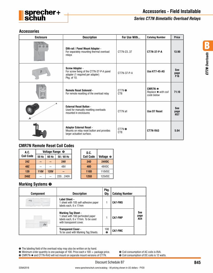
B45visit www.sprecherschuh.com/ecatalog for pricing and the most up to date informationSSNA2018
Discount Schedule B7
B
CT7
N O
verlo
ads
www.sprecherschuh.com/ecatalog - All pricing shown in US dollars - FY20
Marking Systems ➊
Component DescriptionPkg. Qty. Catalog Number
Label Sheet –1 sheet with 105 self-adhesive paper labels each, 6 x 17mm
1 CA7-FMS
See pageA54
Marking Tag Sheet -1 sheet with 160 perforated paper labels each, 6 x 17mm. To be used with transparent cover.
1 CA7-FMP
Transparent Cover -To be used with Marking Tag Sheets.
100➋
CA7-FMC
Enclosure Description For Use With... Catalog Number Price
DIN-rail / Panel Mount Adapter - For separately mounting thermal overload relays
CT7N-23..37 CT7N-37-P-A 13.90
Screw Adapter -For screw fixing of the CT7N-37-P-A panel adapter (1 required per adapter)Pkg. of 10.
CT7N-37-P-A Use KT7-45-AS See page F16
Remote Reset Solenoid -For remote resetting of the overload relay
CT7N ➌CT8
CMR7N-✱Replace ✱ with coil code below
71.10
External Reset Button -Used for manually resetting overloads mounted in enclosures CT7N all Use D7 Reset
See pageH57
Adaptor External Reset -Mounts on relay reset button and provides larger actuation surface.
CT7N ➌CT8 CT7N-RA3 5.04
Accessories - Field InstallableSeries CT7N Bimetallic Overload Relays
Accessories
A.C.Coil Code
Voltage Range ➍ D.C.Coil Code Voltage ➎50 Hz 60 Hz 50 / 60 Hz
24Z ~ ~ 24V 24D 24VDC
48Z ~ ~ 48V 48D 48VDC
120 110V 120V ~ 110D 110VDC
240Z ~ ~ 220…240V 125D 125VDC
CMR7N Remote Reset Coil Codes
➊ The labeling field of the overload relay may also be written on by hand.➋ Minimum order quantity is one package of 100. Price each x 100 = package price.➌ CMR7N-✱ and CT7N-RA3 will not mount on separate mount versions of CT7N.
➍ Coil consumption of AC coils is 8VA.➎ Coil consumption of DC coils is 12 watts.
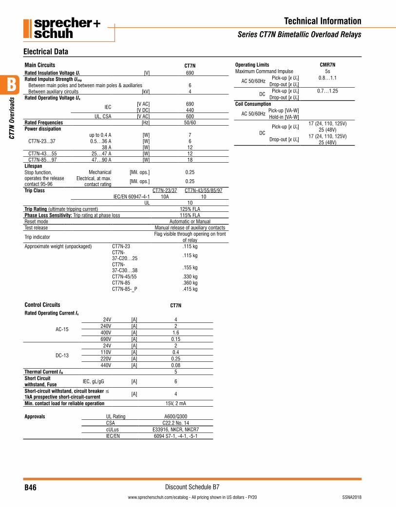
B46visit www.sprecherschuh.com/ecatalog for pricing and the most up to date information SSNA2018
Discount Schedule B7
B
CT7
N O
verlo
ads
www.sprecherschuh.com/ecatalog - All pricing shown in US dollars - FY20
Main Circuits CT7NRated Insulation Voltage Ui [V] 690Rated Impulse Strength Uimp
Between main poles and between main poles & auxiliaries 6Between auxiliary circuits [kV] 4
Rated Operating Voltage Ue
IEC [V AC] 690[V DC] 440
UL, CSA [V AC] 600Rated Frequencies [Hz] 50/60Power dissipation
CT7N-23...37up to 0.4 A [W] 70.5…36 A [W] 6
38 A [W] 12CT7N-43…55 25…47 A [W] 12CT7N-85…97 47…90 A [W] 18
LifespanStop function, operates the release contact 95-96
Mechanical [Mil. ops.] 0.25Electrical, at max.
contact rating [Mil. ops.] 0.25
Trip Class CT7N-23/37 CT7N-43/55/85/97IEC/EN 60947-4-1 10A 10
UL 10Trip Rating (ultimate tripping current) 125% FLAPhase Loss Sensitivity: Trip rating at phase loss 115% FLAReset mode Automatic or ManualTest release Manual release of auxiliary contacts
Trip indicatorFlag visible through opening on front
of relayApproximate weight (unpackaged) CT7N-23 .115 kg
CT7N-37-C20…25 .115 kg
CT7N-37-C30…38 .155 kg
CT7N-45/55 .330 kgCT7N-85 .360 kgCT7N-85-_P .415 kg
Control Circuits CT7NRated Operating Current Ie
AC-15
24V [A] 4240V [A] 2400V [A] 1.6690V [A] 0.15
DC-13
24V [A] 2110V [A] 0.4220V [A] 0.25440V [A] 0.08
Thermal Current Ith 5Short Circuit withstand, Fuse
IEC, gL/gG [A] 6
Short-circuit withstand, circuit breaker ≤ 1kA prospective short-circuit-current [A] 4
Min. contact load for reliable operation 15V, 2 mA
Approvals UL Rating A600/Q300CSA C22.2 No. 14cULus E33916, NKCR, NKCR7IEC/EN 6094 S7-1, -4-1, -5-1
Technical InformationSeries CT7N Bimetallic Overload Relays
Electrical Data
Operating Limits CMR7NMaximum Command Impulse 5s
AC 50/60HzPick-up [x Us] 0.8…1.1
Drop-out [x Us]
DCPick-up [x Us] 0.7…1.25
Drop-out [x Us]Coil Consumption
AC 50/60HzPick-up [VA-W]Hold-in [VA-W]
DCPick-up [x Us]
17 (24, 110, 125V)25 (48V)
Drop-out [x Us]17 (24, 110, 125V)
25 (48V)
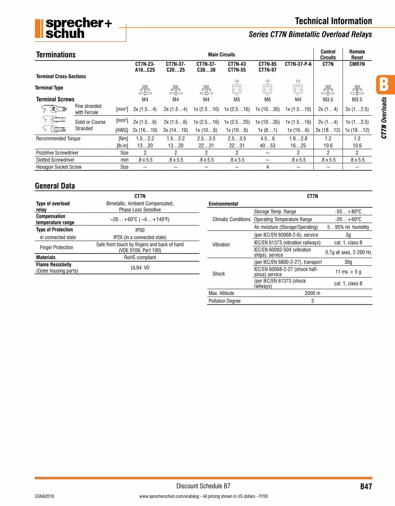
B47visit www.sprecherschuh.com/ecatalog for pricing and the most up to date informationSSNA2018
Discount Schedule B7
B
CT7
N O
verlo
ads
www.sprecherschuh.com/ecatalog - All pricing shown in US dollars - FY20
Technical InformationSeries CT7N Bimetallic Overload Relays
Terminations Main Circuits Control Circuits
Remote Reset
CT7N-23- A16...C25
CT7N-37- C20…25
CT7N-37- C30…38
CT7N-43CT7N-55
CT7N-85CT7N-97
CT7N-37-P-A CT7N CMR7N
Terminal Cross-Sections
Terminal Type
Terminal Screws M4 M4 M4 M5 M6 M4 M3.5 M3.5Fine stranded with Ferrule
[mm2] 2x (1.5…4) 2x (1.5…4) 1x (2.5…10) 1x (2.5…16) 1x (10…35) 1x (1.5…10) 2x (1…4) 2x (1…2.5)
Solid or Course Stranded
[mm2] 2x (1.5…6) 2x (1.5…6) 1x (2.5…16) 1x (2.5…25) 1x (10…35) 1x (1.5…16) 2x (1…4) 1x (1…2.5)
[AWG] 2x (16…10) 2x (14…10) 1x (10…6) 1x (10…6) 1x (8…1) 1x (16…6) 2x (18…12) 1x (16…12)
Recommended Torque [Nm] 1.5…2.2 1.5…2.2 2.5…3.5 2.5…3.5 4.5…6 1.8…2.8 1.2 1.2[lb-in] 13…20 13…20 22…31 22…31 40…53 16…25 10.6 10.6
Pozidrive Screwdriver Size 2 2 2 2 ~ 2 2 2Slotted Screwdriver mm .8 x 5.5 .8 x 5.5 .8 x 5.5 .8 x 5.5 ~ .8 x 5.5 .8 x 5.5 .8 x 5.5Hexagon Socket Screw Size ~ ~ ~ ~ 4 ~ ~ ~
CT7NType of overload relay
Bimetallic, Ambient Compensated, Phase Loss Sensitive
Compensation temperature range
–20…+60°C ( –4…+140°F)
Type of Protection IP00in connected state IP2X (in a connected state)
Finger Protection Safe from touch by fingers and back of hand (VDE 0106, Part 100)
Materials RoHS compliantFlame Resistivity (Outer housing parts)
UL94: V0
CT7NEnvironmental
Climatic Conditions
Storage Temp. Range -55…+80ºC
Operating Temperature Range -20…+60ºC
Air moisture (Storage/Operating) 5…95% rel. humidity
Vibration
(per IEC/EN 60068-2-6), service 3g
IEC/EN 61373 (vibration railways) cat. 1, class BIEC/EN 60092-504 (vibration ships). service 0.7g all axes, 2-200 Hz
Shock
(per IEC/EN 6800-2-27), transport 30gIEC/EN 60068-2-27 (shock half-sinus) service 11 ms > 5 g
(per IEC/EN 61373 (shock railways) cat. 1, class B
Max. Altitude 2000 m
Pollution Degree 3
General Data
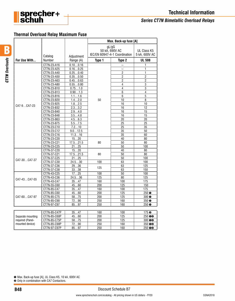
B48visit www.sprecherschuh.com/ecatalog for pricing and the most up to date information SSNA2018
Discount Schedule B7
B
CT7
N O
verlo
ads
www.sprecherschuh.com/ecatalog - All pricing shown in US dollars - FY20
Technical InformationSeries CT7N Bimetallic Overload Relays
Thermal Overload Relay Maximum Fuse
For Use With...Catalog Number
Adjustment Range (A)
Max. Back-up fuse [A]
gL/gG50 kA, 690V AC
IEC/EN 60947-4-1 CoordinationUL Class K5
5 kA, 600V AC
Type 1 Type 2 UL 508
CA7-9…CA7-23
CT7N-23-A16 0.10…0.16
50
~ 1CT7N-23-A25 0.16…0.25 ~ 1CT7N-23-A40 0.25…0.40 2 1CT7N-23-A50 0.35…0.50 2 2CT7N-23-A63 0.45…0.63 2 2CT7N-23-A80 0.55…0.80 4 3CT7N-23-B10 0.75…1.0 4 3CT7N-23-B13 0.90…1.3 6 4CT7N-23-B16 1.1…1.6 6 5CT7N-23-B20 1.4…2.0 10 8CT7N-23-B25 1.8…2.5 16 10CT7N-23-B32 2.3…3.2 16 12CT7N-23-B40 2.9…4.0 16 15CT7N-23-B48 3.5…4.8 16 15CT7N-23-B63 4.5…6.3 20 20CT7N-23-B75 5.5…7.5 25 25CT7N-23-C10 7.2…10 25 35CT7N-23-C12 9.0…12.5 35 50CT7N-23-C16 11.3…16 35 60CT7N-23-C20 15…20
8040 80
CT7N-23-C21 17.5…21.5 50 80CT7N-23-C25 21…25 50 100
CA7-30…CA7-37
CT7N-37-C20 15…2080
40 80CT7N-37-C21 17.5…21.5 50 80CT7N-37-C25 21…25 50 100CT7N-37-C30 24.5…30 100 63 100CT7N-37-C36 29…36
12563 125
CT7N-37-C38 33…38 63 150
CA7-43…CA7-55
CT7N-43-C25 17…25 100 50 100CT7N-43-C36 24.5…36 125 80 125CT7N-43-C47 35…47 160 100 175CT7N-55-C60 45…60 200 125 150
CA7-60…CA7-97
CT7N-85-C47 35…47 160 100 175CT7N-85-C60 45…60 200 125 250 ➊CT7N-85-C75 58…75 200 125 300 ➊CT7N-85-C90 72…90 250 160 350 ➊CT7N-97-C97 85…97 250 160 250 ➊
Separate mounting required (Panel-mounted device)
CT7N-85-C47P 35…47 160 100 175 ➋CT7N-85-C60P 45…60 200 125 250 ➊➋
CT7N-85-C75P 58…75 200 125 300 ➊➋
CT7N-85-C90P 72…90 250 160 350 ➊➋
CT7N-97-C97P 85…97 250 160 250 ➊➋
➊ Max. Back-up fuse [A], UL Class K5, 10 kA, 600V AC➋ Only in combination with CA7 Contactors.

B49visit www.sprecherschuh.com/ecatalog for pricing and the most up to date informationSSNA2018
Discount Schedule B7
B
CT7
N O
verlo
ads
www.sprecherschuh.com/ecatalog - All pricing shown in US dollars - FY20
+ -
+ -
DC
96 98
95 97
2 4 6
Typical IEC Wiring Schematic
CT7N-23-A16…A40 Overload Relays
(a)
(b)
Connection Diagrams
Tripping Characteristics
These tripping characteristics refer to IEC/EN 60947-1 and are average values from cold start at an ambient temperature of 20ºC. Trip time is pictured as a function of operating current. With the device at max. operating temperature, the trip time decreases to approximately 25% of the shown value.(a) Tripping characteristics 3-poles from the cold state(b) Tripping characteristics 2-poles from the cold state
Technical InformationSeries CT7N Bimetallic Overload Relays
+ -
+ -
DC
96 98
95 97
2 4 6
Typical IEC Wiring Schematic
CT7N-23-A16…A40 Overload Relays
(a)
(b)
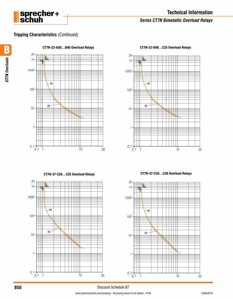
B50visit www.sprecherschuh.com/ecatalog for pricing and the most up to date information SSNA2018
Discount Schedule B7
B
CT7
N O
verlo
ads
www.sprecherschuh.com/ecatalog - All pricing shown in US dollars - FY20
Technical InformationSeries CT7N Bimetallic Overload Relays
Tripping Characteristics (Continued)
CT7N-23-A50…B40 Overload Relays
(a)
(b)
CT7N-23-B48…C25 Overload Relays
(a)
(b)
CT7N-37-C20…C25 Overload Relays
(a)
(b)
CT7N-37-C30…C38 Overload Relays
(a)
(b)
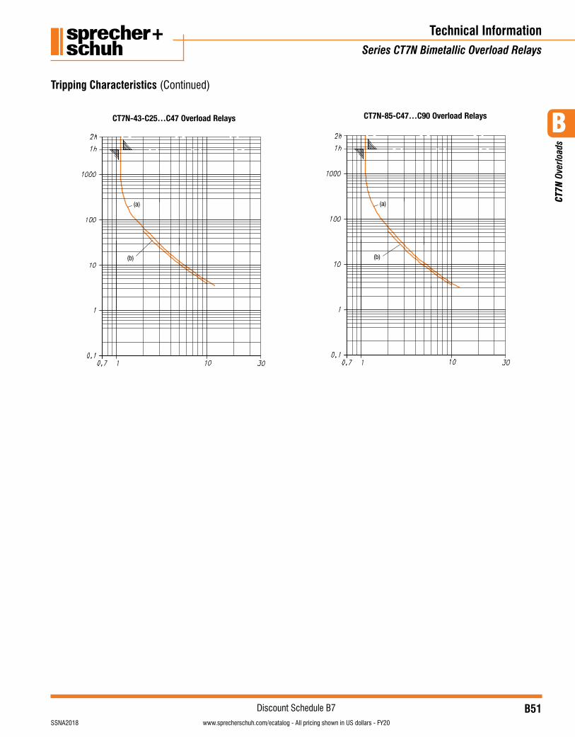
B51visit www.sprecherschuh.com/ecatalog for pricing and the most up to date informationSSNA2018
Discount Schedule B7
B
CT7
N O
verlo
ads
www.sprecherschuh.com/ecatalog - All pricing shown in US dollars - FY20
Technical InformationSeries CT7N Bimetallic Overload Relays
Tripping Characteristics (Continued)
CT7N-43-C25…C47 Overload Relays
(a)
(b)
CT7N-85-C47…C90 Overload Relays
(a)
(b)
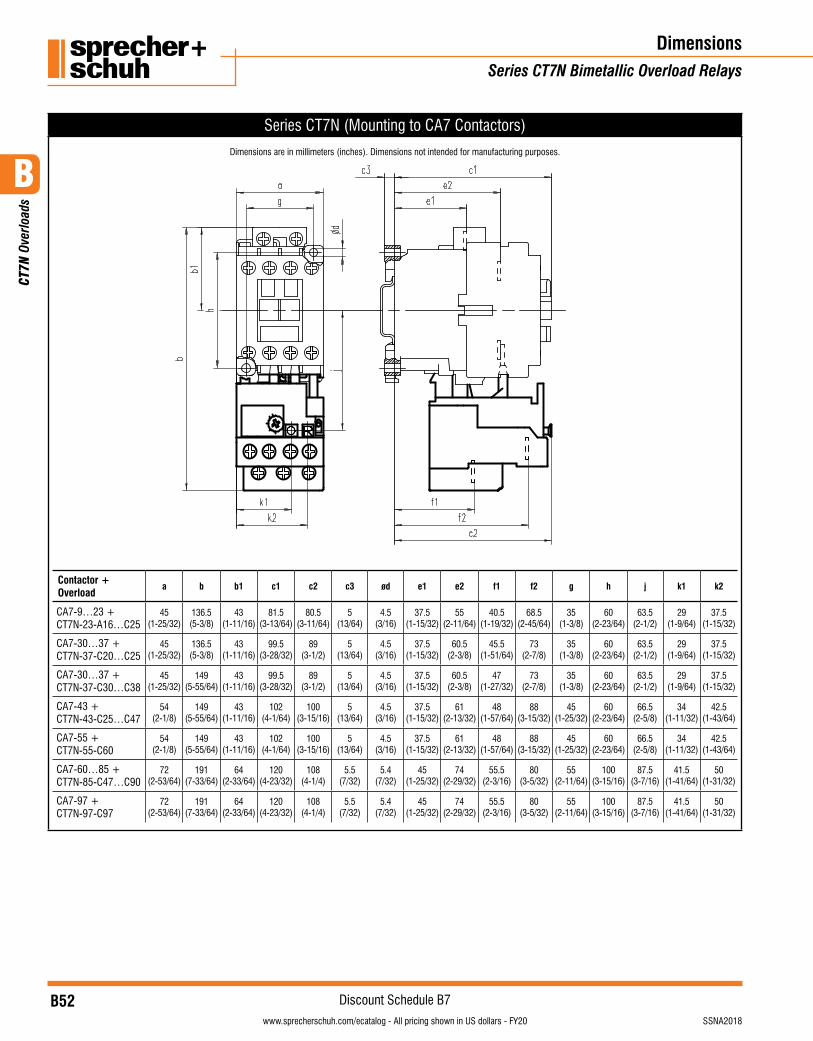
B52visit www.sprecherschuh.com/ecatalog for pricing and the most up to date information SSNA2018
Discount Schedule B7
B
CT7
N O
verlo
ads
www.sprecherschuh.com/ecatalog - All pricing shown in US dollars - FY20
Series CT7N (Mounting to CA7 Contactors)
Dimensions are in millimeters (inches). Dimensions not intended for manufacturing purposes.
Contactor + Overload
a b b1 c1 c2 c3 ød e1 e2 f1 f2 g h j k1 k2
CA7-9…23 + CT7N-23-A16…C25
45(1-25/32)
136.5(5-3/8)
43(1-11/16)
81.5(3-13/64)
80.5(3-11/64)
5(13/64)
4.5(3/16)
37.5(1-15/32)
55(2-11/64)
40.5(1-19/32)
68.5(2-45/64)
35(1-3/8)
60(2-23/64)
63.5(2-1/2)
29(1-9/64)
37.5(1-15/32)
CA7-30…37 +CT7N-37-C20…C25
45(1-25/32)
136.5(5-3/8)
43(1-11/16)
99.5(3-28/32)
89(3-1/2)
5(13/64)
4.5(3/16)
37.5(1-15/32)
60.5(2-3/8)
45.5(1-51/64)
73(2-7/8)
35(1-3/8)
60(2-23/64)
63.5(2-1/2)
29(1-9/64)
37.5(1-15/32)
CA7-30…37 +CT7N-37-C30…C38
45(1-25/32)
149(5-55/64)
43(1-11/16)
99.5(3-28/32)
89(3-1/2)
5(13/64)
4.5(3/16)
37.5(1-15/32)
60.5(2-3/8)
47(1-27/32)
73(2-7/8)
35(1-3/8)
60(2-23/64)
63.5(2-1/2)
29(1-9/64)
37.5(1-15/32)
CA7-43 +CT7N-43-C25…C47
54(2-1/8)
149(5-55/64)
43(1-11/16)
102(4-1/64)
100(3-15/16)
5(13/64)
4.5(3/16)
37.5(1-15/32)
61(2-13/32)
48(1-57/64)
88(3-15/32)
45(1-25/32)
60(2-23/64)
66.5(2-5/8)
34(1-11/32)
42.5(1-43/64)
CA7-55 +CT7N-55-C60
54(2-1/8)
149(5-55/64)
43(1-11/16)
102(4-1/64)
100(3-15/16)
5(13/64)
4.5(3/16)
37.5(1-15/32)
61(2-13/32)
48(1-57/64)
88(3-15/32)
45(1-25/32)
60(2-23/64)
66.5(2-5/8)
34(1-11/32)
42.5(1-43/64)
CA7-60…85 +CT7N-85-C47…C90
72(2-53/64)
191(7-33/64)
64(2-33/64)
120(4-23/32)
108(4-1/4)
5.5(7/32)
5.4(7/32)
45(1-25/32)
74(2-29/32)
55.5(2-3/16)
80(3-5/32)
55(2-11/64)
100(3-15/16)
87.5(3-7/16)
41.5(1-41/64)
50(1-31/32)
CA7-97 +CT7N-97-C97
72(2-53/64)
191(7-33/64)
64(2-33/64)
120(4-23/32)
108(4-1/4)
5.5(7/32)
5.4(7/32)
45(1-25/32)
74(2-29/32)
55.5(2-3/16)
80(3-5/32)
55(2-11/64)
100(3-15/16)
87.5(3-7/16)
41.5(1-41/64)
50(1-31/32)
DimensionsSeries CT7N Bimetallic Overload Relays

B53visit www.sprecherschuh.com/ecatalog for pricing and the most up to date informationSSNA2018
Discount Schedule B7
B
CT7
N O
verlo
ads
www.sprecherschuh.com/ecatalog - All pricing shown in US dollars - FY20
Series CT7N Separate Mount (+ Adaptor)
Dimensions are in millimeters (inches). Dimensions not intended for manufacturing purposes.
CT7N-23..37 with Panel Mount Adapter CT7N-85…97 Separate Mount
Overload + DIN Rail/Panel Mounting Adapter
a b b1 c1 c2 c3 ød e1 f1 f2 g h k1 k2
CT7N-23-A16…C25 + CT7N-37-P-ACT7N-37-C20…C25 + CT7N-37-P-A
45(1-25/32)
89.5(3-17/32)
50(1-31/32)
69(2-23/32)
66(2-19/32)
4(5/32)
4.5(3/16)
38(1-31-64)
26(1-1/32)
54(2-1/8)
15(19/32)
90(3-35/64)
29(1-9/64)
37.5(1-15/32)
CT7N-37-C30…C38 + CT7N-37-P-A
45(1-25/32)
91.5(3-39/64)
50(1-31/32)
69(2-23/32)
66(2-19/32)
4(5/32)
4.5(3/16)
38(1-31-64)
28(1-7/64)
54(2-1/8)
15(19/32)
90(3-35/64)
29(1-9/64)
37.5(1-15/32)
CT7N-85-C47P…CT7N-97-C97P 56(2-13/64)
82(3-15/64)
46(1-13-16)
99.5(3-28/32)
~4
(5/32)4.5
(3/16)56
(2-13/64)47.5
(1-7/8)87
(3-27/64)~
60(2-23/64)
41.5(1-41/64)
50(1-31/32)
CT7N-RA3 External Reset Adaptor CMR7N Remote Reset Solenoid
DimensionsSeries CT7N Bimetallic Overload Relays
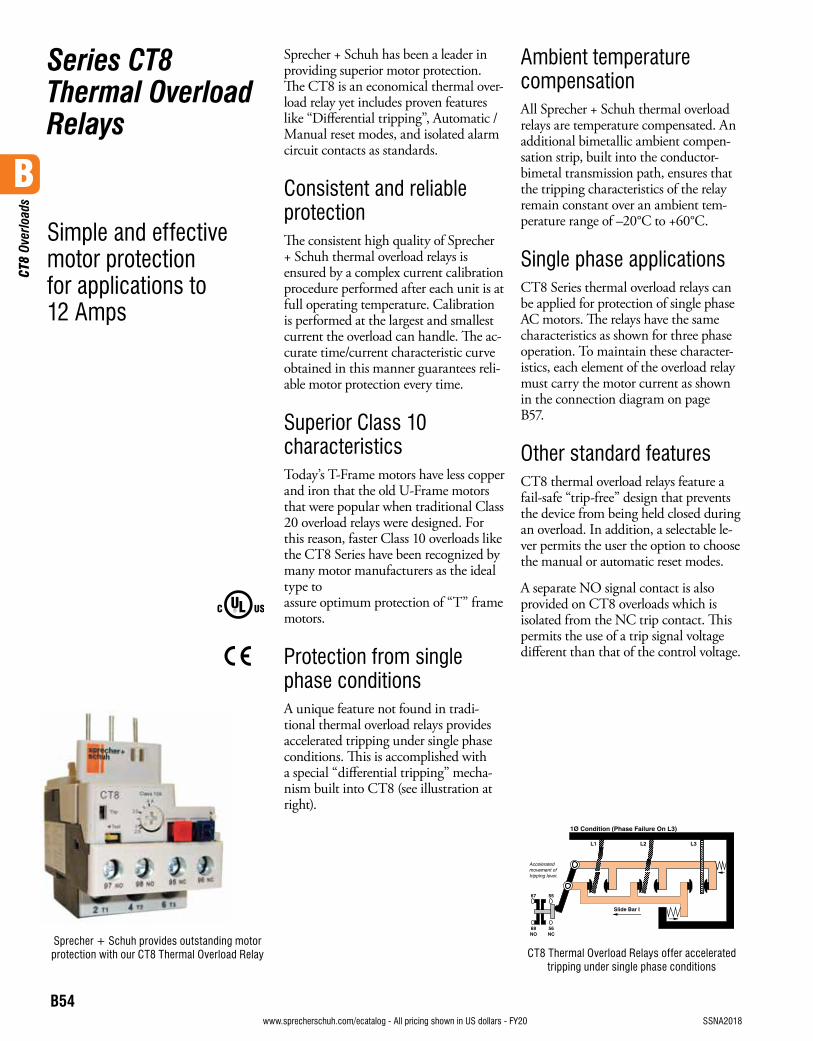
B
CT8
Ove
rload
s
B54visit www.sprecherschuh.com/ecatalog for pricing and the most up to date information SSNA2018www.sprecherschuh.com/ecatalog - All pricing shown in US dollars - FY20
Series CT8 Thermal OverloadRelays
Simple and effective motor protection for applications to 12 Amps
Sprecher + Schuh has been a leader in providing superior motor protection. The CT8 is an economical thermal over-load relay yet includes proven features like “Differential tripping”, Automatic / Manual reset modes, and isolated alarm circuit contacts as standards.
Consistent and reliable protectionThe consistent high quality of Sprecher + Schuh thermal overload relays is ensured by a complex current calibration procedure performed after each unit is at full operating temperature. Calibration is performed at the largest and smallest current the overload can handle. The ac-curate time/current characteristic curve obtained in this manner guarantees reli-able motor protection every time.
Superior Class 10 characteristicsToday’s T-Frame motors have less copper and iron that the old U-Frame motors that were popular when traditional Class 20 overload relays were designed. For this reason, faster Class 10 overloads like the CT8 Series have been recognized by many motor manufacturers as the ideal type to assure optimum protection of “T” frame motors.
Protection from single phase conditionsA unique feature not found in tradi-tional thermal overload relays provides accelerated tripping under single phase conditions. This is accomplished with a special “differential tripping” mecha-nism built into CT8 (see illustration at right).
Ambient temperature compensationAll Sprecher + Schuh thermal overload relays are temperature compensated. An additional bimetallic ambient compen-sation strip, built into the conductor-bimetal transmission path, ensures that the tripping characteristics of the relay remain constant over an ambient tem-perature range of –20°C to +60°C.
Single phase applicationsCT8 Series thermal overload relays can be applied for protection of single phase AC motors. The relays have the same characteristics as shown for three phase operation. To maintain these character-istics, each element of the overload relay must carry the motor current as shown in the connection diagram on page B57.
Other standard featuresCT8 thermal overload relays feature a fail-safe “trip-free” design that prevents the device from being held closed during an overload. In addition, a selectable le-ver permits the user the option to choose the manual or automatic reset modes.
A separate NO signal contact is also provided on CT8 overloads which is isolated from the NC trip contact. This permits the use of a trip signal voltage different than that of the control voltage.
CT8 Thermal Overload Relays offer accelerated tripping under single phase conditions
Sprecher + Schuh provides outstanding motor protection with our CT8 Thermal Overload Relay
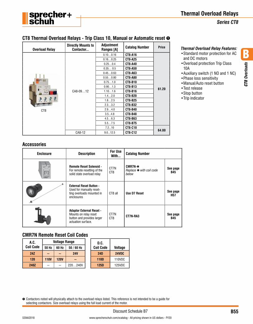
B
CT8
Ove
rload
s
B55visit www.sprecherschuh.com/ecatalog for pricing and the most up to date informationSSNA2018
Discount Schedule B7www.sprecherschuh.com/ecatalog - All pricing shown in US dollars - FY20
Overload RelayDirectly Mounts to
Contactor...Adjustment Ranges [A]
Catalog Number Price
CT8
CA8-09…12
0.10…0.16 CT8-A16
61.20
0.16…0.25 CT8-A250.25…0.4 CT8-A400.35… 0.5 CT8-A500.45…0.63 CT8-A630.55…0.80 CT8-A800.75…1.0 CT8-B100.90…1.3 CT8-B131.10…1.6 CT8-B161.4…2.0 CT8-B201.8…2.5 CT8-B252.3…3.2 CT8-B322.9…4.0 CT8-B403.5...4.8 CT8-B484.5…6.3 CT8-B635.5…7.5 CT8-B757.2...10 CT8-C10
64.00CA8-12 9.0...12.5 CT8-C12
CT8 Thermal Overload Relays - Trip Class 10, Manual or Automatic reset ➊
Thermal Overload RelaysSeries CT8
Accessories Description For Use with... Catalog NumberPrice Each
Remote Reset -For remote resetting
AllCT8
CMR8-✱ 47
CT8 Thermal Overload Relay Accessories
ACCoil Code
Voltage Range50 Hz 60 Hz
24Z 24V 24V
120 110V 120V
240 240V 240V
DCCoil Code Voltage
24D 24V
48D 48V
115D 115V
➊ Contactors noted will physically attach to the overload relays listed. This reference is not intended to be a guide for selecting contactors. Size overload relays using the full load current of the motor.
Thermal Overload Relay Features:• Standard motor protection for AC
and DC motors• Overload protection Trip Class
10A• Auxiliary switch (1 NO and 1 NC)• Phase loss sensitivity• Manual/Auto reset button• Test release• Stop button• Trip indicator
Enclosure Description For Use With... Catalog Number
Remote Reset Solenoid -For remote resetting of the solid state overload relay
CT7N CT8
CMR7N-✱Replace ✱ with coil code below
See pageB45
External Reset Button -Used for manually reset-ting overloads mounted in enclosures
CT8 all Use D7 Reset See pageH57
Adaptor External Reset -Mounts on relay reset button and provides larger actuation surface.
CT7N CT8
CT7N-RA3 See pageB45
CMR7N Remote Reset Coil CodesA.C.
Coil CodeVoltage Range D.C.
Coil Code Voltage 50 Hz 60 Hz 50 / 60 Hz
24Z ~ ~ 24V 24D 24VDC
120 110V 120V ~ 110D 110VDC
240Z ~ ~ 220…240V 125D 125VDC
Accessories
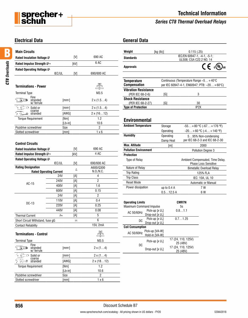
B
CT8
Ove
rload
s
B56visit www.sprecherschuh.com/ecatalog for pricing and the most up to date information SSNA2018
Discount Schedule B7www.sprecherschuh.com/ecatalog - All pricing shown in US dollars - FY20
Technical InformationSeries CT8 Thermal Overload Relays
Electrical Data
Main Circuits
Rated Insulation Voltage Ui [V] 690 AC
Rated Impulse Strength Uimp [kV] 6 AC
Rated Operating Voltage Ue
IEC/UL [V] 690/600 AC
Terminations - Power
Terminal Type M3.5Fine stranded w/ ferrule
[mm2] 2 x (1.5…4)
Solid or coarse stranded
[mm2] 2 x (1.5…4)
[AWG] 2 x (16…12)
Torque Requirement [Nm] 1.2[Lb-in] 10.6
Pozidrive screwdriver Size 2Slotted screwdriver [mm] 1 x 6
Control CircuitsRated Insulation Voltage Ui [V] 690 AC
Rated Impulse Strength Uimp [kV] 4 AC
Rated Operating Voltage Ue
IEC/UL [V] 690/600 ACRating Designation
Rated Operating CurrentIe
A600/Q300N.O./N.C.
AC-15
24V [A] 4
240V [A] 2
400V [A] 1.6
600V [A] 0.15
DC-13
24V [A] 2
110V [A] 0.4
220V [A] 0.25
440V [A] 0.08
Thermal Current Ithe [A] 5
Short Circuit Withstand, fuse gG [A] 6
Contact Reliability 15V, 2mA
Terminations - Control
Terminal Type M3.5Fine stranded w/ ferrule
[mm2] 2 x (1…4)
Solid or coarse stranded
[mm2] 2 x (1…4)
[AWG] 2 x (18…12)
Torque Requirement [Nm] 1.2[Lb-in] 10.6
Pozidrive screwdriver Size 2Slotted screwdriver [mm] 1 x 6
General Data
Weight [kg (lb)] 0.115 (.25)
Standards IEC/EN 60947-1, -4-1, -5-1; UL508; CSA C22.2 NO. 14
Approvals
TemperatureCompensation
Continuous (Temperature Range –5…+40°Cper IEC 60947-4-1, EN60947; PTB: –20…+60°C)
Vibration Resistance(PER IEC 68-2-6) [G] 3
Shock Resistance(PER IEC 68-2-27) [G] 30
Type of Protection IP2X
EnvironmentalAmbient Temperature Storage -55…+80 ºC (-67…+176 ºF)
Operating -20…+60 ºC (-4…+140 ºF)Humidity Operating
Damp Heat5…95% Non-condensing
per IEC 68-2-3 and IEC 68-2-30
Max. Altitude [m] 2000Pollution Environment Pollution Degree 3Protection
Type of Relay Ambient Compensated, Time Delay, Phase Loss Sensitive
Nature of Relay Bimetallic Overload RelayTrip Rating 125% FLATrip Class IEC: 10A, UL 10Reset Mode Automatic or ManualPower dissipation up to 0.4 A 7 W
0.5…12.5 A 6 W
Operating Limits CMR7NMaximum Command Impulse 5s
AC 50/60HzPick-up [x Us] 0.8…1.1
Drop-out [x Us]
DCPick-up [x Us] 0.7…1.25
Drop-out [x Us]Coil Consumption
AC 50/60HzPick-up [VA-W]Hold-in [VA-W]
DCPick-up [x Us]
17 (24, 110, 125V)25 (48V)
Drop-out [x Us]17 (24, 110, 125V)
25 (48V)
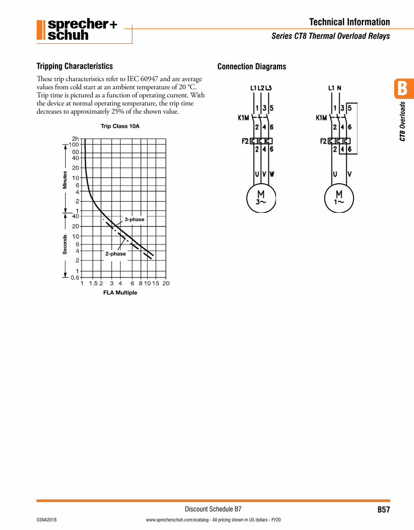
B
CT8
Ove
rload
s
B57visit www.sprecherschuh.com/ecatalog for pricing and the most up to date informationSSNA2018
Discount Schedule B7www.sprecherschuh.com/ecatalog - All pricing shown in US dollars - FY20
Technical Information Series CT8 Thermal Overload Relays
Tripping CharacteristicsThese trip characteristics refer to IEC 60947 and are average values from cold start at an ambient temperature of 20 °C. Trip time is pictured as a function of operating current. With the device at normal operating temperature, the trip time decreases to approximately 25% of the shown value.
FLAÊMultiple
2-phase
3-phase
TripÊClassÊ10A
setuniM
sdnoceS
Connection Diagrams
FLAÊMultiple
2-phase
3-phase
TripÊClassÊ10A
setuniM
sdnoceS
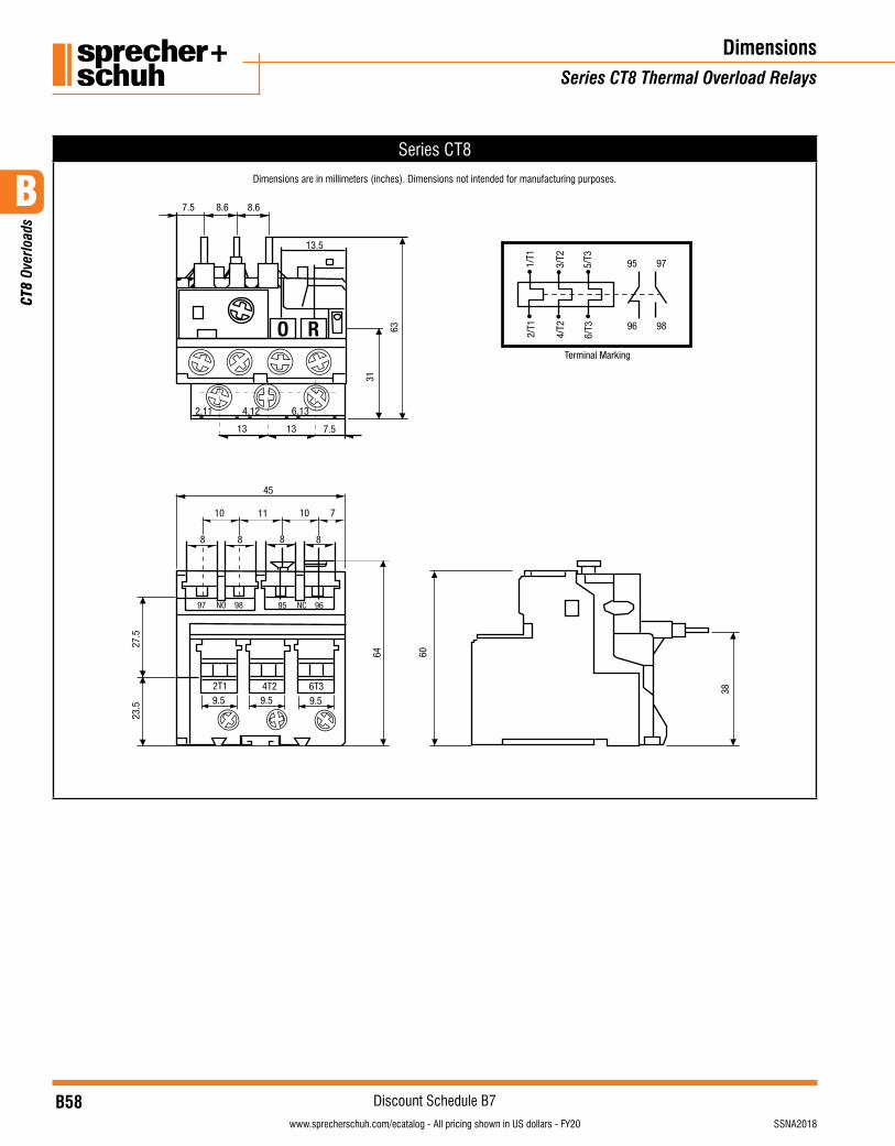
B
CT8
Ove
rload
s
B58visit www.sprecherschuh.com/ecatalog for pricing and the most up to date information SSNA2018
Discount Schedule B7www.sprecherschuh.com/ecatalog - All pricing shown in US dollars - FY20
DimensionsSeries CT8 Thermal Overload Relays
Series CT8
Dimensions are in millimeters (inches). Dimensions not intended for manufacturing purposes.
O R
7.5 8.6 8.6
13.5
63
31
2.11 4.12 6.13
7.51313
Terminal Marking
1/T1
3/T2
5/T3
2/T1
4/T2
6/T3
10 11 10 7
45
8 8 88
9.52T1 4T2 6T3
9.5 9.5
23.5
27.5
64
97 NO 98 95 NC 96
60
38
97
96
95
98