output filters design guidefiles.danfoss.com/download/drives/doc_mg90n402.pdf · • reduction of...
TRANSCRIPT

MAKING MODERN LIVING POSSIBLE
Output Filters Design GuideVLT® AutomationDrive FC 300
VLT® AQUA Drive FC 200VLT® HVAC Drive FC 100
Contents
1 How to Read this Design Guide 3
1.1.2 Abbreviations 3
2 Safety and Conformity 4
2.1 Safety Precautions 4
2.1.1 CE Conformity and Labelling 4
3 Introduction to Output Filters 5
3.1 Why use Output Filters 5
3.2 Protection of Motor Insulation 5
3.2.1 The Output Voltage 5
3.3 Reduction of Motor Acoustic Noise 7
3.4 Reduction of High Frequency Electromagnetic Noise in the Motor Cable 7
3.5 What are Bearing Currents and Shaft Voltages? 8
3.5.1 Mitigation of Premature Bearing Wear-Out 8
3.5.2 Measuring Electric Discharges in the Motor Bearings 9
3.6 Which Filter for which Purpose 10
3.6.1 du/dt Filters 10
3.6.2 Sine-wave Filters 12
3.6.3 High-Frequency Common-Mode Core Kits 14
4 Selection of Output Filters 15
4.1 How to Select the Correct Output Filter 15
4.1.1 Product Overview 15
4.1.2 HF-CM Selection 17
4.2 Electrical Data - du/dt Filters 18
4.3 Electrical Data - Sine-wave Filters 20
4.4 Sine-Wave Filters 25
4.4.1 du/dt Filters 26
4.4.2 Sine-Wave Foot Print Filter 27
5 How to Install 28
5.1 Mechanical Mounting 28
5.1.1 Safety Requirements for Mechanical Installation 28
5.1.2 Mounting 28
5.1.3 Earthing 29
5.1.4 Screening 29
5.2 Mechanical Dimensions 30
5.2.1 Sketches 30
6 How to Programme the Frequency Converter 38
Contents Output Filters Design Guide
MG.90.N4.02 - VLT® is a registered Danfoss trademark 1
6.1.1 Parameter Settings for Operation with Sine-wave Filter 38
Index 39
Contents Output Filters Design Guide
2 MG.90.N4.02 - VLT® is a registered Danfoss trademark
1 How to Read this Design Guide
This Design Guide will introduce all aspects of output filtersfor your VLT® FC Series Drive; From choosing the rightoutput filter for the application to instructions about how toinstall it and how to program the Frequency Converter.
Danfoss technical literature is also available online atwww.danfoss.com/BusinessAreas/DrivesSolutions/Documentations/Technical+Documentation.
1.1.1 Symbols
Symbols used in this manual:
NOTEIndicates something to be noted by the reader.
CAUTIONIndicates a general warning.
WARNINGIndicates a high-voltage warning.
✮ Indicates default setting
1.1.2 Abbreviations
Alternating current AC
American wire gauge AWG
Ampere/AMP A
Automatic Motor Adaptation AMA
Current limit ILIM
Degrees Celsius °C
Direct current DC
Drive Dependent D-TYPE
Electro Magnetic Compatibility EMC
Electronic Thermal Relay ETR
Drive FC
Gram g
Hertz Hz
Kilohertz kHz
Local Control Panel LCP
Meter m
Millihenry Inductance mH
Milliampere mA
Millisecond ms
Minute min
Motion Control Tool MCT
Nanofarad nF
Newton Meters Nm
Nominal motor current IM,N
Nominal motor frequency fM,N
Nominal motor power PM,N
Nominal motor voltage UM,N
Parameter par.
Protective Extra Low Voltage PELV
Rated Inverter Output Current IINV
Revolutions Per Minute RPM
Second s
Synchronous Motor Speed ns
Torque limit TLIM
Volts V
IVLT,MAX The maximum output current.
IVLT,N The rated output currentsupplied by the frequencyconverter.
How to Read this Design Gui... Output Filters Design Guide
MG.90.N4.02 - VLT® is a registered Danfoss trademark 3
1 1
2 Safety and Conformity
2.1 Safety Precautions
Equipment containing electrical componentsmay not be disposed of together with domesticwaste.It must be separately collected with electricaland electronic waste according to local andcurrently valid legislation.
MCC 101/102Design Guide
2.1.1 CE Conformity and Labelling
What is CE Conformity and Labelling?The purpose of CE labelling is to avoid technical tradeobstacles within EFTA and the EU. The EU has introduced theCE label as a simple way of showing whether a productcomplies with the relevant EU directives. The CE label saysnothing about the specifications or quality of the product.The low-voltage directive (73/23/EEC)Frequency converters must be CE labelled in accordancewith the low-voltage directive of January 1, 1997. Thedirective applies to all electrical equipment and appliancesused in the 50 - 1000 V AC and the 75 - 1500 V DC voltageranges. Danfoss CE-labels in accordance with the directiveand issues a declaration of conformity upon request.
Warnings
CAUTIONWhen in use the filter surface temperature rises. DO NOTtouch the filter during operation.
WARNINGNever work on a filter in operation. Touching the electricalparts may be fatal - even after the equipment has beendisconnected from the drive or motor.
CAUTIONBefore servicing the filter, wait at least the voltage dischargetime stated in the Design Guide for the corresponding VLT®
to avoid electrical shock hazard.
NOTENever attempt to repair a defect filter.
NOTEThe filters presented in this design guide are speciallydesigned and tested for Danfoss Drives frequency converters(FC 102/202/301 and 302). Danfoss takes no resposibility forthe use of third party output filters.
NOTEThe phased out LC-filters that were developed for theVLT5000 series and are not compatible with the VLT FC-series frequency converters.However, the new filters are compatible with both FC-seriesand VLT 5000-series
NOTE690V applications:For motors not specially designed for frequency converteroperation or without double insulation, Danfoss highlyrecommend the use of either du/dt or Sine-Wave filters.
NOTESine-wave filters can be used at switching frequencies higherthan the nominal switching frequency, but should never beused at switching frequencies with less than 20% lower thanthe nominal switching frequency.
NOTEdu/dt filters, unlike Sine-wave filters, can be used at lowerswitching frequency than the nominal switching frequency,but higher switching frequency will cause the overheating ofthe filter and should be avoided.
Safety and Conformity Output Filters Design Guide
4 MG.90.N4.02 - VLT® is a registered Danfoss trademark
22
3 Introduction to Output Filters
3.1 Why use Output Filters
This chapter describes why and when to use Output Filterswith Danfoss Drives frequency converters. It is divided intothree sections:
• Protection of Motor Insulation
• Reduction of Motor Acoustic Noise
• Reduction of High Frequency ElectromagneticNoise in Motor Cable
3.2 Protection of Motor Insulation
3.2.1 The Output Voltage
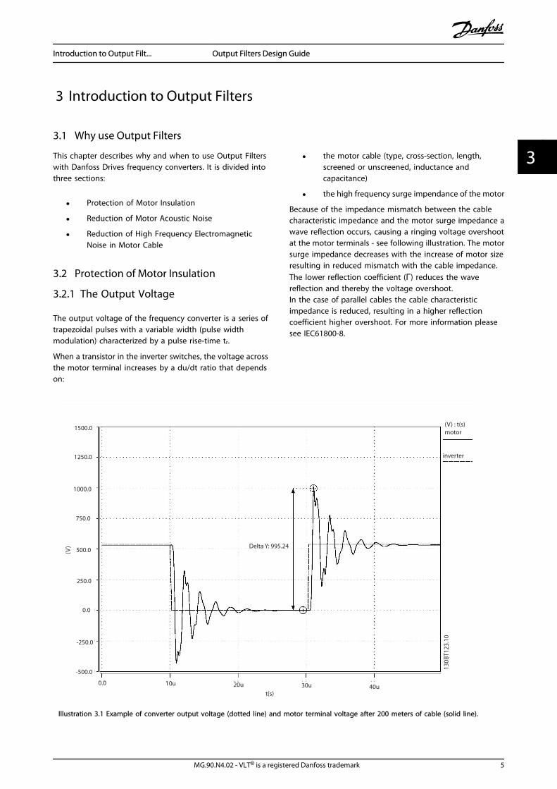
The output voltage of the frequency converter is a series oftrapezoidal pulses with a variable width (pulse widthmodulation) characterized by a pulse rise-time tr.
When a transistor in the inverter switches, the voltage acrossthe motor terminal increases by a du/dt ratio that dependson:
• the motor cable (type, cross-section, length,screened or unscreened, inductance andcapacitance)
• the high frequency surge impendance of the motor
Because of the impedance mismatch between the cablecharacteristic impedance and the motor surge impedance awave reflection occurs, causing a ringing voltage overshootat the motor terminals - see following illustration. The motorsurge impedance decreases with the increase of motor sizeresulting in reduced mismatch with the cable impedance.The lower reflection coefficient (Γ) reduces the wavereflection and thereby the voltage overshoot.In the case of parallel cables the cable characteristicimpedance is reduced, resulting in a higher reflectioncoefficient higher overshoot. For more information pleasesee IEC61800-8.
Illustration 3.1 Example of converter output voltage (dotted line) and motor terminal voltage after 200 meters of cable (solid line).
Introduction to Output Filt... Output Filters Design Guide
MG.90.N4.02 - VLT® is a registered Danfoss trademark 5
3 3
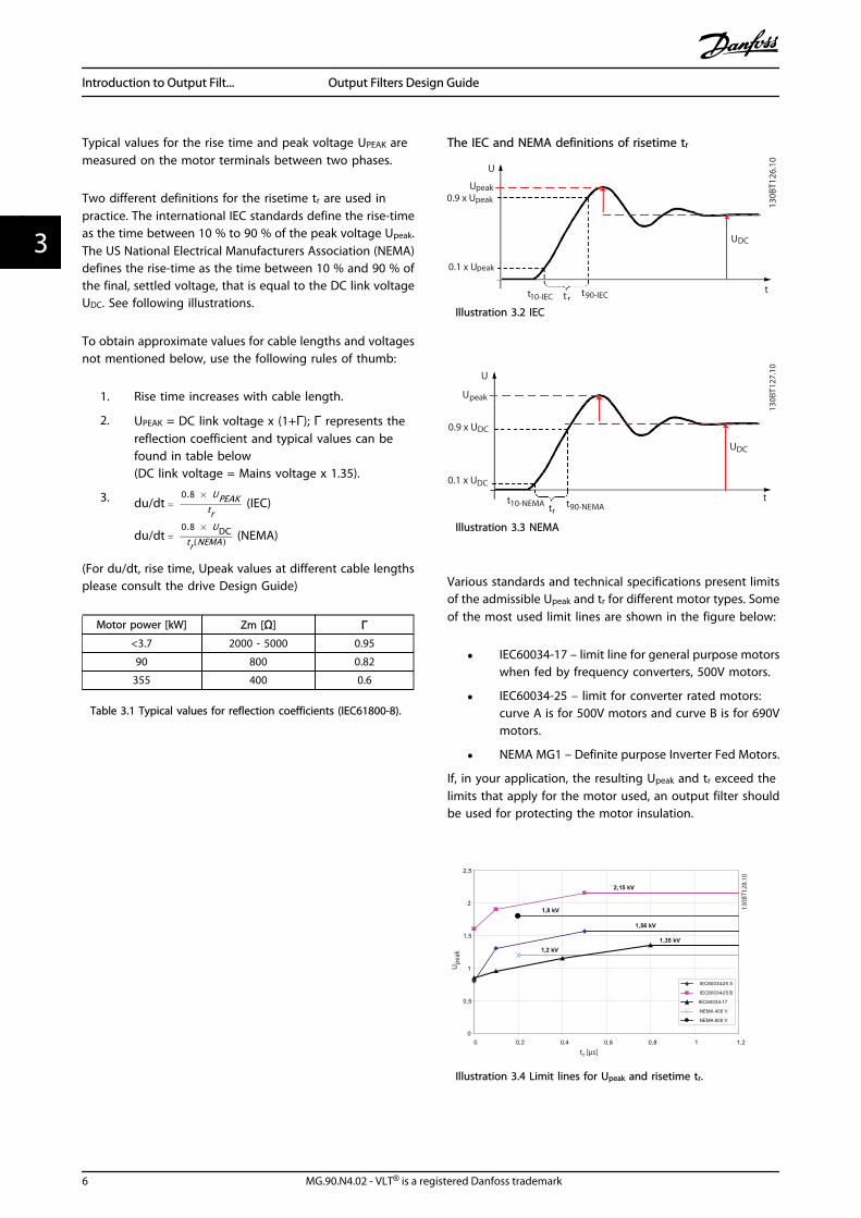
Typical values for the rise time and peak voltage UPEAK aremeasured on the motor terminals between two phases.
Two different definitions for the risetime tr are used inpractice. The international IEC standards define the rise-timeas the time between 10 % to 90 % of the peak voltage Upeak.The US National Electrical Manufacturers Association (NEMA)defines the rise-time as the time between 10 % and 90 % ofthe final, settled voltage, that is equal to the DC link voltageUDC. See following illustrations.
To obtain approximate values for cable lengths and voltagesnot mentioned below, use the following rules of thumb:
1. Rise time increases with cable length.
2. UPEAK = DC link voltage x (1+Γ); Γ represents thereflection coefficient and typical values can befound in table below(DC link voltage = Mains voltage x 1.35).
3. du/dt = 0.8 × UPEAK
tr (IEC)
du/dt = 0.8 × UDCtr(NEMA ) (NEMA)
(For du/dt, rise time, Upeak values at different cable lengthsplease consult the drive Design Guide)
Motor power [kW] Zm [Ω] Γ<3.7 2000 - 5000 0.95
90 800 0.82
355 400 0.6
Table 3.1 Typical values for reflection coefficients (IEC61800-8).
The IEC and NEMA definitions of risetime tr
Illustration 3.2 IEC
Illustration 3.3 NEMA
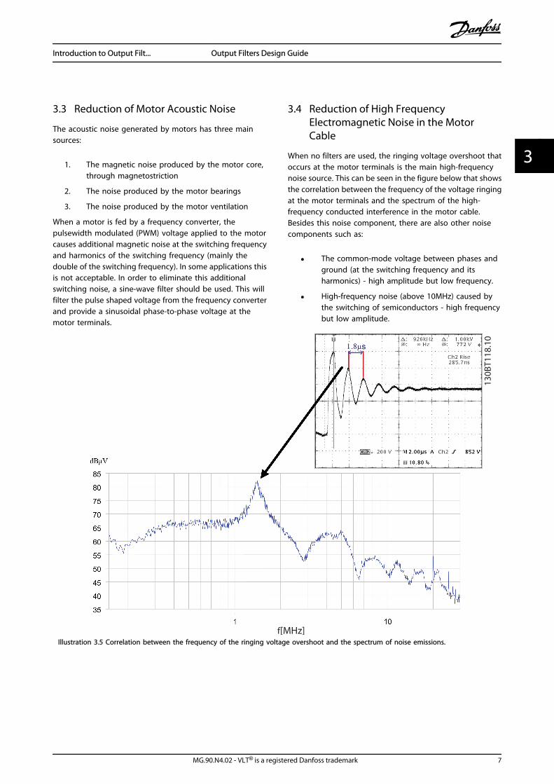
Various standards and technical specifications present limitsof the admissible Upeak and tr for different motor types. Someof the most used limit lines are shown in the figure below:
• IEC60034-17 – limit line for general purpose motorswhen fed by frequency converters, 500V motors.
• IEC60034-25 – limit for converter rated motors:curve A is for 500V motors and curve B is for 690Vmotors.
• NEMA MG1 – Definite purpose Inverter Fed Motors.
If, in your application, the resulting Upeak and tr exceed thelimits that apply for the motor used, an output filter shouldbe used for protecting the motor insulation.
Illustration 3.4 Limit lines for Upeak and risetime tr.
Introduction to Output Filt... Output Filters Design Guide
6 MG.90.N4.02 - VLT® is a registered Danfoss trademark
33
3.3 Reduction of Motor Acoustic Noise
The acoustic noise generated by motors has three mainsources:
1. The magnetic noise produced by the motor core,through magnetostriction
2. The noise produced by the motor bearings
3. The noise produced by the motor ventilation
When a motor is fed by a frequency converter, thepulsewidth modulated (PWM) voltage applied to the motorcauses additional magnetic noise at the switching frequencyand harmonics of the switching frequency (mainly thedouble of the switching frequency). In some applications thisis not acceptable. In order to eliminate this additionalswitching noise, a sine-wave filter should be used. This willfilter the pulse shaped voltage from the frequency converterand provide a sinusoidal phase-to-phase voltage at themotor terminals.
3.4 Reduction of High FrequencyElectromagnetic Noise in the MotorCable
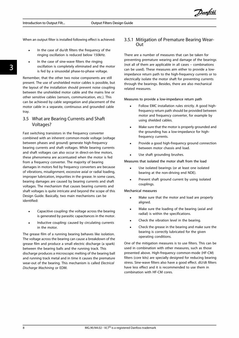
When no filters are used, the ringing voltage overshoot thatoccurs at the motor terminals is the main high-frequencynoise source. This can be seen in the figure below that showsthe correlation between the frequency of the voltage ringingat the motor terminals and the spectrum of the high-frequency conducted interference in the motor cable.Besides this noise component, there are also other noisecomponents such as:
• The common-mode voltage between phases andground (at the switching frequency and itsharmonics) - high amplitude but low frequency.
• High-frequency noise (above 10MHz) caused bythe switching of semiconductors - high frequencybut low amplitude.
Illustration 3.5 Correlation between the frequency of the ringing voltage overshoot and the spectrum of noise emissions.
Introduction to Output Filt... Output Filters Design Guide
MG.90.N4.02 - VLT® is a registered Danfoss trademark 7
3 3
When an output filter is installed following effect is achieved:
• In the case of du/dt filters the frequency of theringing oscillation is reduced below 150kHz.
• In the case of sine-wave filters the ringingoscillation is completely eliminated and the motoris fed by a sinusoidal phase-to-phase voltage.
Remember, that the other two noise components are stillpresent. The use of unshielded motor cables is possible, butthe layout of the installation should prevent noise couplingbetween the unshielded motor cable and the mains line orother sensitive cables (sensors, communication, etc.). Thiscan be achieved by cable segregation and placement of themotor cable in a separate, continuous and grounded cabletray.
3.5 What are Bearing Currents and ShaftVoltages?
Fast switching transistors in the frequency convertercombined with an inherent common-mode voltage (voltagebetween phases and ground) generate high-frequencybearing currents and shaft voltages. While bearing currentsand shaft voltages can also occur in direct-on-line motors,these phenomena are accentuated when the motor is fedfrom a frequency converter. The majority of bearingdamages in motors fed by frequency converters are becauseof vibrations, misalignment, excessive axial or radial loading,improper lubrication, impurities in the grease. In some cases,bearing damages are caused by bearing currents and shaftvoltages. The mechanism that causes bearing currents andshaft voltages is quite intricate and beyond the scope of thisDesign Guide. Basically, two main mechanisms can beidentified:
• Capacitive coupling: the voltage across the bearingis generated by parasitic capacitances in the motor.
• Inductive coupling: caused by circulating currentsin the motor.
The grease film of a running bearing behaves like isolation.The voltage across the bearing can cause a breakdown of thegrease film and produce a small electric discharge (a spark)between the bearing balls and the running track. Thisdischarge produces a microscopic melting of the bearing balland running track metal and in time it causes the prematurewear-out of the bearing. This mechanism is called ElectricalDischarge Machining or EDM.
3.5.1 Mitigation of Premature Bearing Wear-Out
There are a number of measures that can be taken forpreventing premature wearing and damage of the bearings(not all of them are applicable in all cases – combinationscan be used). These measures aim either to provide a low-impedance return path to the high-frequency currents or toelectrically isolate the motor shaft for preventing currentsthrough the bearings. Besides, there are also mechanicalrelated measures.
Measures to provide a low-impedance return path
• Follow EMC installation rules strictly. A good high-frequency return path should be provided betweenmotor and frequency converter, for example byusing shielded cables.
• Make sure that the motor is properly grounded andthe grounding has a low-impedance for high-frequency currents.
• Provide a good high-frequency ground connectionbetween motor chassis and load.
• Use shaft grounding brushes.
Measures that isolated the motor shaft from the load
• Use isolated bearings (or at least one isolatedbearing at the non-driving end NDE).
• Prevent shaft ground current by using isolatedcouplings.
Mechanical measures
• Make sure that the motor and load are properlyaligned.
• Make sure the loading of the bearing (axial andradial) is within the specifications.
• Check the vibration level in the bearing.
• Check the grease in the bearing and make sure thebearing is correctly lubricated for the givenoperating conditions.
One of the mitigation measures is to use filters. This can beused in combination with other measures, such as thosepresented above. High-frequency common-mode (HF-CM)filters (core kits) are specially designed for reducing bearingstress. Sine-wave filters also have a good effect. dU/dt filtershave less effect and it is recommended to use them incombination with HF-CM cores.
Introduction to Output Filt... Output Filters Design Guide
8 MG.90.N4.02 - VLT® is a registered Danfoss trademark
33
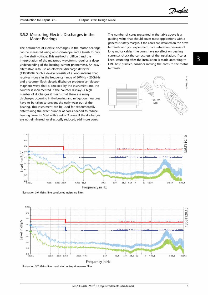
3.5.2 Measuring Electric Discharges in theMotor Bearings
The occurrence of electric discharges in the motor bearingscan be measured using an oscilloscope and a brush to pickup the shaft voltage. This method is difficult and theinterpretation of the measured waveforms requires a deepunderstanding of the bearing current phenomena. An easyalternative is to use an electrical discharge detector(130B8000). Such a device consists of a loop antenna thatreceives signals in the frequency range of 50MHz – 200MHzand a counter. Each electric discharge produces an electro-magnetic wave that is detected by the instrument and thecounter is incremented. If the counter displays a highnumber of discharges it means that there are manydischarges occurring in the bearing and mitigation measureshave to be taken to prevent the early wear out of thebearing. This instrument can be used for experimentallydetermining the exact number of cores needed to reducebearing currents. Start with a set of 2 cores. If the dischargesare not eliminated, or drastically reduced, add more cores.
The number of cores presented in the table above is aguiding value that should cover most applications with agenerous safety margin. If the cores are installed on the driveterminals and you experiment core saturation because oflong motor cables (the cores have no effect on bearingcurrents), check the correctness of the installation. If coreskeep saturating after the installation is made according toEMC best practice, consider moving the cores to the motorterminals.
129
50 - 200 MHz
130B
B729
.10
Lev
el i
n d
Bµ
V
Frequency in Hz1
30
BT
11
9.1
0
Illustration 3.6 Mains line conducted noise, no filter.
Illustration 3.7 Mains line conducted noise, sine-wave filter.
Introduction to Output Filt... Output Filters Design Guide
MG.90.N4.02 - VLT® is a registered Danfoss trademark 9
3 3
3.6 Which Filter for which Purpose
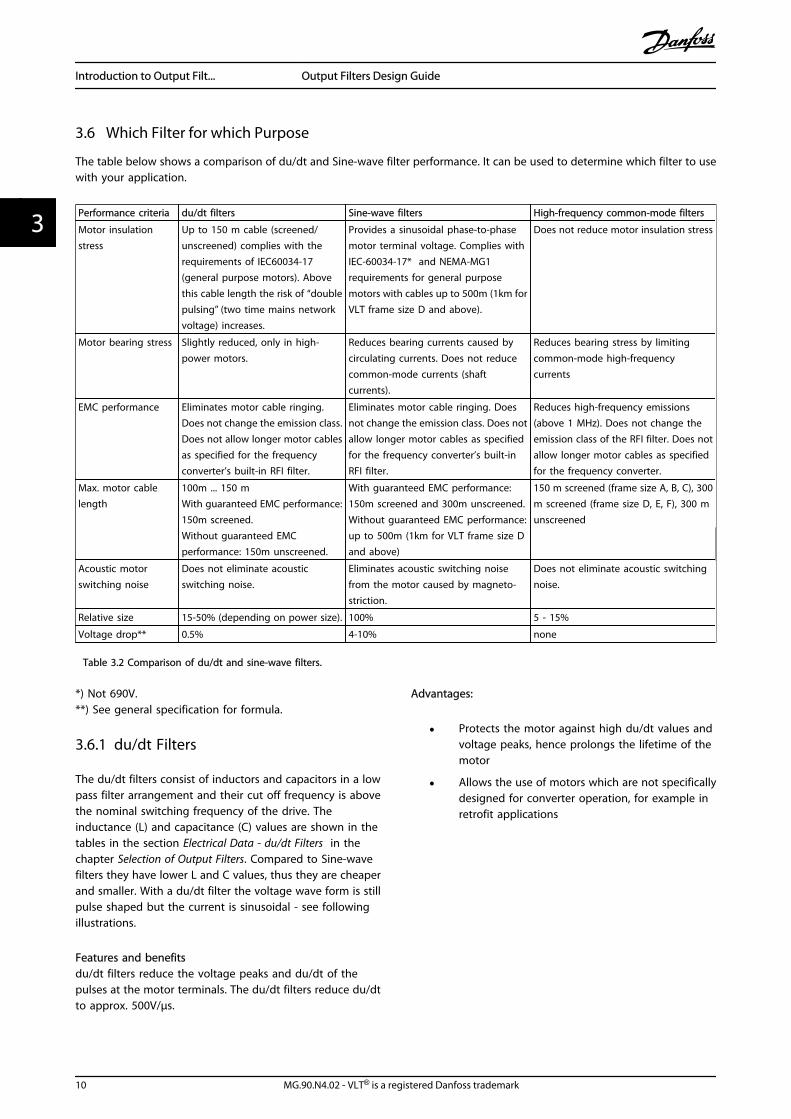
The table below shows a comparison of du/dt and Sine-wave filter performance. It can be used to determine which filter to usewith your application.
Performance criteria du/dt filters Sine-wave filters High-frequency common-mode filters
Motor insulationstress
Up to 150 m cable (screened/unscreened) complies with therequirements of IEC60034-17(general purpose motors). Abovethis cable length the risk of “doublepulsing” (two time mains networkvoltage) increases.
Provides a sinusoidal phase-to-phasemotor terminal voltage. Complies withIEC-60034-17* and NEMA-MG1requirements for general purposemotors with cables up to 500m (1km forVLT frame size D and above).
Does not reduce motor insulation stress
Motor bearing stress Slightly reduced, only in high-power motors.
Reduces bearing currents caused bycirculating currents. Does not reducecommon-mode currents (shaftcurrents).
Reduces bearing stress by limitingcommon-mode high-frequencycurrents
EMC performance Eliminates motor cable ringing.Does not change the emission class.Does not allow longer motor cablesas specified for the frequencyconverter’s built-in RFI filter.
Eliminates motor cable ringing. Doesnot change the emission class. Does notallow longer motor cables as specifiedfor the frequency converter’s built-inRFI filter.
Reduces high-frequency emissions(above 1 MHz). Does not change theemission class of the RFI filter. Does notallow longer motor cables as specifiedfor the frequency converter.
Max. motor cablelength
100m ... 150 mWith guaranteed EMC performance:150m screened.Without guaranteed EMCperformance: 150m unscreened.
With guaranteed EMC performance:150m screened and 300m unscreened.Without guaranteed EMC performance:up to 500m (1km for VLT frame size Dand above)
150 m screened (frame size A, B, C), 300m screened (frame size D, E, F), 300 munscreened
Acoustic motorswitching noise
Does not eliminate acousticswitching noise.
Eliminates acoustic switching noisefrom the motor caused by magneto-striction.
Does not eliminate acoustic switchingnoise.
Relative size 15-50% (depending on power size). 100% 5 - 15%
Voltage drop** 0.5% 4-10% none
Table 3.2 Comparison of du/dt and sine-wave filters.
*) Not 690V.**) See general specification for formula.
3.6.1 du/dt Filters
The du/dt filters consist of inductors and capacitors in a lowpass filter arrangement and their cut off frequency is abovethe nominal switching frequency of the drive. Theinductance (L) and capacitance (C) values are shown in thetables in the section Electrical Data - du/dt Filters in thechapter Selection of Output Filters. Compared to Sine-wavefilters they have lower L and C values, thus they are cheaperand smaller. With a du/dt filter the voltage wave form is stillpulse shaped but the current is sinusoidal - see followingillustrations.
Features and benefitsdu/dt filters reduce the voltage peaks and du/dt of thepulses at the motor terminals. The du/dt filters reduce du/dtto approx. 500V/μs.
Advantages:
• Protects the motor against high du/dt values andvoltage peaks, hence prolongs the lifetime of themotor
• Allows the use of motors which are not specificallydesigned for converter operation, for example inretrofit applications
Introduction to Output Filt... Output Filters Design Guide
10 MG.90.N4.02 - VLT® is a registered Danfoss trademark
33
Application areas:Danfoss recommends the use of du/dt filters in the followingapplications:
• Applications with frequent regenerative braking
• Motors that are not rated for frequency converteroperation and not complying with IEC600034-25
• Motors placed in aggressive environments orrunning at high temperatures
• Applications with risk of flash over
• Installations using old motors (retrofit) or generalpurpose motors not complying with IEC 600034-25
• Applications with short motor cables (less than 15meters)
• 690 V applications
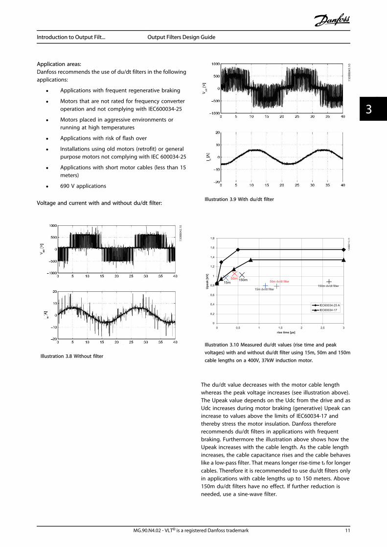
Voltage and current with and without du/dt filter:
Illustration 3.8 Without filter
Illustration 3.9 With du/dt filter
13
0B
B11
3.1
1
Up
ea
k [
kV
]
15m dv/dt filter
rise time [µs]
150m dv/dt filter
50m dv/dt filter
Illustration 3.10 Measured du/dt values (rise time and peakvoltages) with and without du/dt filter using 15m, 50m and 150mcable lengths on a 400V, 37kW induction motor.
The du/dt value decreases with the motor cable lengthwhereas the peak voltage increases (see illustration above).The Upeak value depends on the Udc from the drive and asUdc increases during motor braking (generative) Upeak canincrease to values above the limits of IEC60034-17 andthereby stress the motor insulation. Danfoss thereforerecommends du/dt filters in applications with frequentbraking. Furthermore the illustration above shows how theUpeak increases with the cable length. As the cable lengthincreases, the cable capacitance rises and the cable behaveslike a low-pass filter. That means longer rise-time tr for longercables. Therefore it is recommended to use du/dt filters onlyin applications with cable lengths up to 150 meters. Above150m du/dt filters have no effect. If further reduction isneeded, use a sine-wave filter.
Introduction to Output Filt... Output Filters Design Guide
MG.90.N4.02 - VLT® is a registered Danfoss trademark 11
3 3
Filter features:
• IP00 and IP20 enclosure in the entire power range
• Side by side mounting with the drive
• Reduced size, weight and price compared to thesine-wave filters
• Possibility of connecting screened cables withincluded decoupling plate
• Compatible with all control principles includingflux and VVC+
• Filters wall mounted up to 177A and floor mountedabove that size
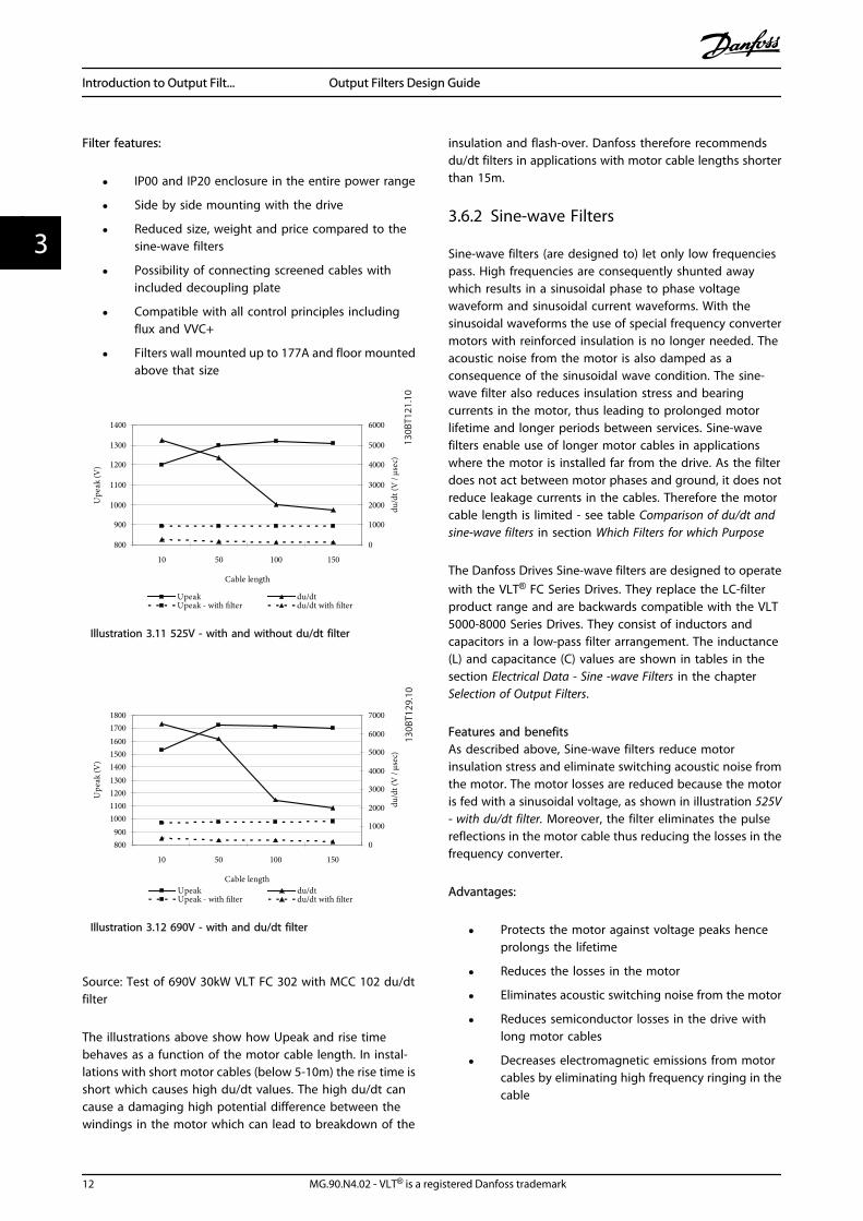
Illustration 3.11 525V - with and without du/dt filter
Illustration 3.12 690V - with and du/dt filter
Source: Test of 690V 30kW VLT FC 302 with MCC 102 du/dtfilter
The illustrations above show how Upeak and rise timebehaves as a function of the motor cable length. In instal-lations with short motor cables (below 5-10m) the rise time isshort which causes high du/dt values. The high du/dt cancause a damaging high potential difference between thewindings in the motor which can lead to breakdown of the
insulation and flash-over. Danfoss therefore recommendsdu/dt filters in applications with motor cable lengths shorterthan 15m.
3.6.2 Sine-wave Filters
Sine-wave filters (are designed to) let only low frequenciespass. High frequencies are consequently shunted awaywhich results in a sinusoidal phase to phase voltagewaveform and sinusoidal current waveforms. With thesinusoidal waveforms the use of special frequency convertermotors with reinforced insulation is no longer needed. Theacoustic noise from the motor is also damped as aconsequence of the sinusoidal wave condition. The sine-wave filter also reduces insulation stress and bearingcurrents in the motor, thus leading to prolonged motorlifetime and longer periods between services. Sine-wavefilters enable use of longer motor cables in applicationswhere the motor is installed far from the drive. As the filterdoes not act between motor phases and ground, it does notreduce leakage currents in the cables. Therefore the motorcable length is limited - see table Comparison of du/dt andsine-wave filters in section Which Filters for which Purpose
The Danfoss Drives Sine-wave filters are designed to operatewith the VLT® FC Series Drives. They replace the LC-filterproduct range and are backwards compatible with the VLT5000-8000 Series Drives. They consist of inductors andcapacitors in a low-pass filter arrangement. The inductance(L) and capacitance (C) values are shown in tables in thesection Electrical Data - Sine -wave Filters in the chapterSelection of Output Filters.
Features and benefitsAs described above, Sine-wave filters reduce motorinsulation stress and eliminate switching acoustic noise fromthe motor. The motor losses are reduced because the motoris fed with a sinusoidal voltage, as shown in illustration 525V- with du/dt filter. Moreover, the filter eliminates the pulsereflections in the motor cable thus reducing the losses in thefrequency converter.
Advantages:
• Protects the motor against voltage peaks henceprolongs the lifetime
• Reduces the losses in the motor
• Eliminates acoustic switching noise from the motor
• Reduces semiconductor losses in the drive withlong motor cables
• Decreases electromagnetic emissions from motorcables by eliminating high frequency ringing in thecable
Introduction to Output Filt... Output Filters Design Guide
12 MG.90.N4.02 - VLT® is a registered Danfoss trademark
33
• Reduces electromagnetic interference fromunscreened motor cables
• Reduces the bearing current thus prolonging thelifetime of the motor
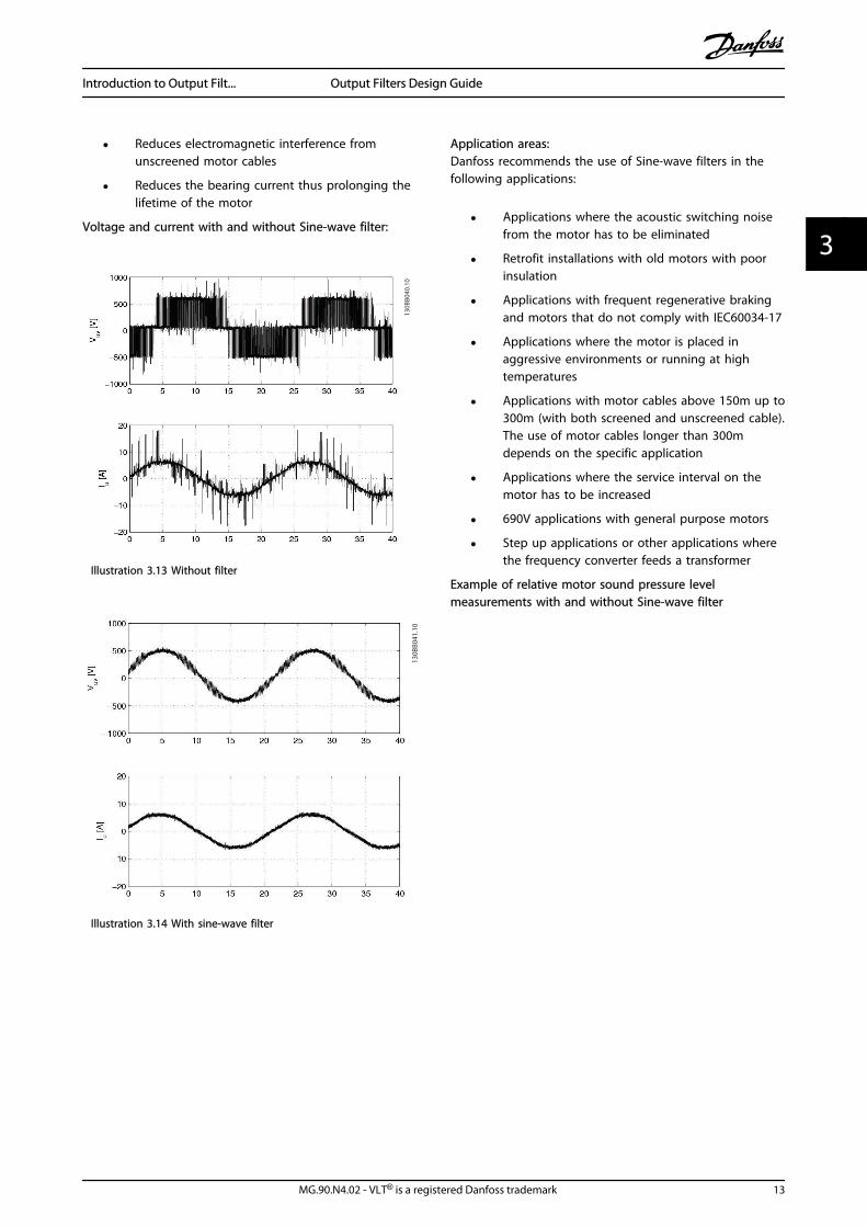
Voltage and current with and without Sine-wave filter:
Illustration 3.13 Without filter
Illustration 3.14 With sine-wave filter
Application areas:Danfoss recommends the use of Sine-wave filters in thefollowing applications:
• Applications where the acoustic switching noisefrom the motor has to be eliminated
• Retrofit installations with old motors with poorinsulation
• Applications with frequent regenerative brakingand motors that do not comply with IEC60034-17
• Applications where the motor is placed inaggressive environments or running at hightemperatures
• Applications with motor cables above 150m up to300m (with both screened and unscreened cable).The use of motor cables longer than 300mdepends on the specific application
• Applications where the service interval on themotor has to be increased
• 690V applications with general purpose motors
• Step up applications or other applications wherethe frequency converter feeds a transformer
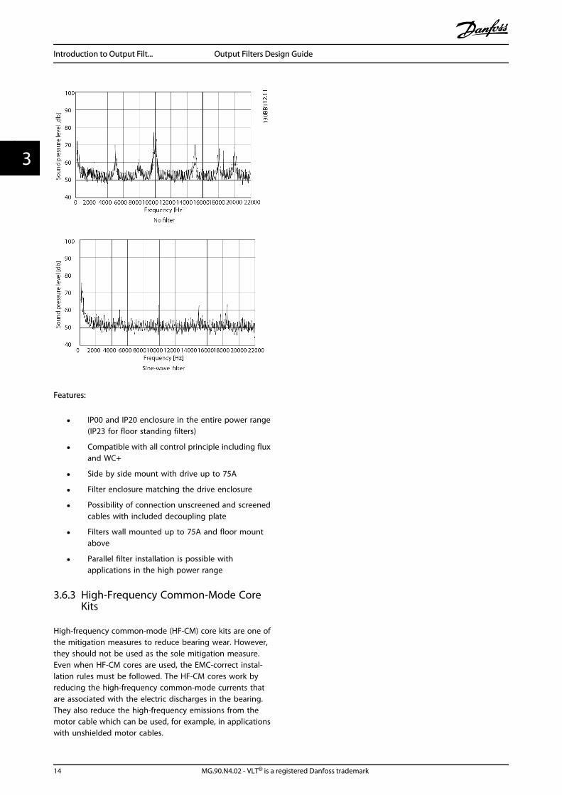
Example of relative motor sound pressure levelmeasurements with and without Sine-wave filter
Introduction to Output Filt... Output Filters Design Guide
MG.90.N4.02 - VLT® is a registered Danfoss trademark 13
3 3
Features:
• IP00 and IP20 enclosure in the entire power range(IP23 for floor standing filters)
• Compatible with all control principle including fluxand WC+
• Side by side mount with drive up to 75A
• Filter enclosure matching the drive enclosure
• Possibility of connection unscreened and screenedcables with included decoupling plate
• Filters wall mounted up to 75A and floor mountabove
• Parallel filter installation is possible withapplications in the high power range
3.6.3 High-Frequency Common-Mode CoreKits
High-frequency common-mode (HF-CM) core kits are one ofthe mitigation measures to reduce bearing wear. However,they should not be used as the sole mitigation measure.Even when HF-CM cores are used, the EMC-correct instal-lation rules must be followed. The HF-CM cores work byreducing the high-frequency common-mode currents thatare associated with the electric discharges in the bearing.They also reduce the high-frequency emissions from themotor cable which can be used, for example, in applicationswith unshielded motor cables.
Introduction to Output Filt... Output Filters Design Guide
14 MG.90.N4.02 - VLT® is a registered Danfoss trademark
33
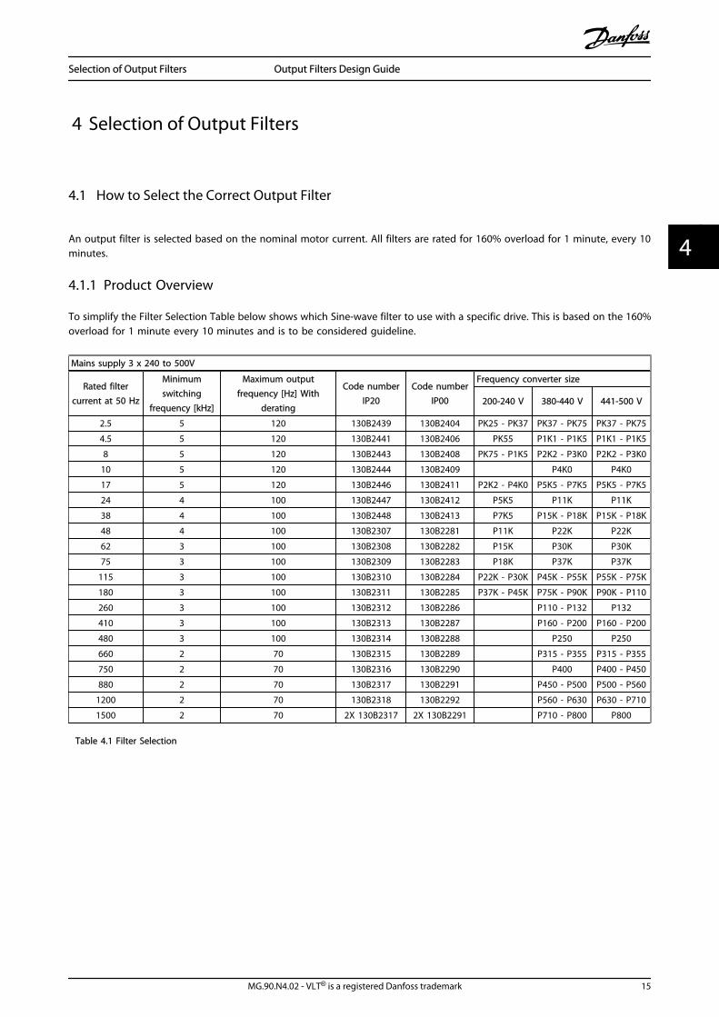
4 Selection of Output Filters
4.1 How to Select the Correct Output Filter
An output filter is selected based on the nominal motor current. All filters are rated for 160% overload for 1 minute, every 10minutes.
4.1.1 Product Overview
To simplify the Filter Selection Table below shows which Sine-wave filter to use with a specific drive. This is based on the 160%overload for 1 minute every 10 minutes and is to be considered guideline.
Mains supply 3 x 240 to 500V
Rated filtercurrent at 50 Hz
Minimumswitching
frequency [kHz]
Maximum outputfrequency [Hz] With
derating
Code numberIP20
Code numberIP00
Frequency converter size
200-240 V 380-440 V 441-500 V
2.5 5 120 130B2439 130B2404 PK25 - PK37 PK37 - PK75 PK37 - PK75
4.5 5 120 130B2441 130B2406 PK55 P1K1 - P1K5 P1K1 - P1K5
8 5 120 130B2443 130B2408 PK75 - P1K5 P2K2 - P3K0 P2K2 - P3K0
10 5 120 130B2444 130B2409 P4K0 P4K0
17 5 120 130B2446 130B2411 P2K2 - P4K0 P5K5 - P7K5 P5K5 - P7K5
24 4 100 130B2447 130B2412 P5K5 P11K P11K
38 4 100 130B2448 130B2413 P7K5 P15K - P18K P15K - P18K
48 4 100 130B2307 130B2281 P11K P22K P22K
62 3 100 130B2308 130B2282 P15K P30K P30K
75 3 100 130B2309 130B2283 P18K P37K P37K
115 3 100 130B2310 130B2284 P22K - P30K P45K - P55K P55K - P75K
180 3 100 130B2311 130B2285 P37K - P45K P75K - P90K P90K - P110
260 3 100 130B2312 130B2286 P110 - P132 P132
410 3 100 130B2313 130B2287 P160 - P200 P160 - P200
480 3 100 130B2314 130B2288 P250 P250
660 2 70 130B2315 130B2289 P315 - P355 P315 - P355
750 2 70 130B2316 130B2290 P400 P400 - P450
880 2 70 130B2317 130B2291 P450 - P500 P500 - P560
1200 2 70 130B2318 130B2292 P560 - P630 P630 - P710
1500 2 70 2X 130B2317 2X 130B2291 P710 - P800 P800
Table 4.1 Filter Selection
Selection of Output Filters Output Filters Design Guide
MG.90.N4.02 - VLT® is a registered Danfoss trademark 15
4 4
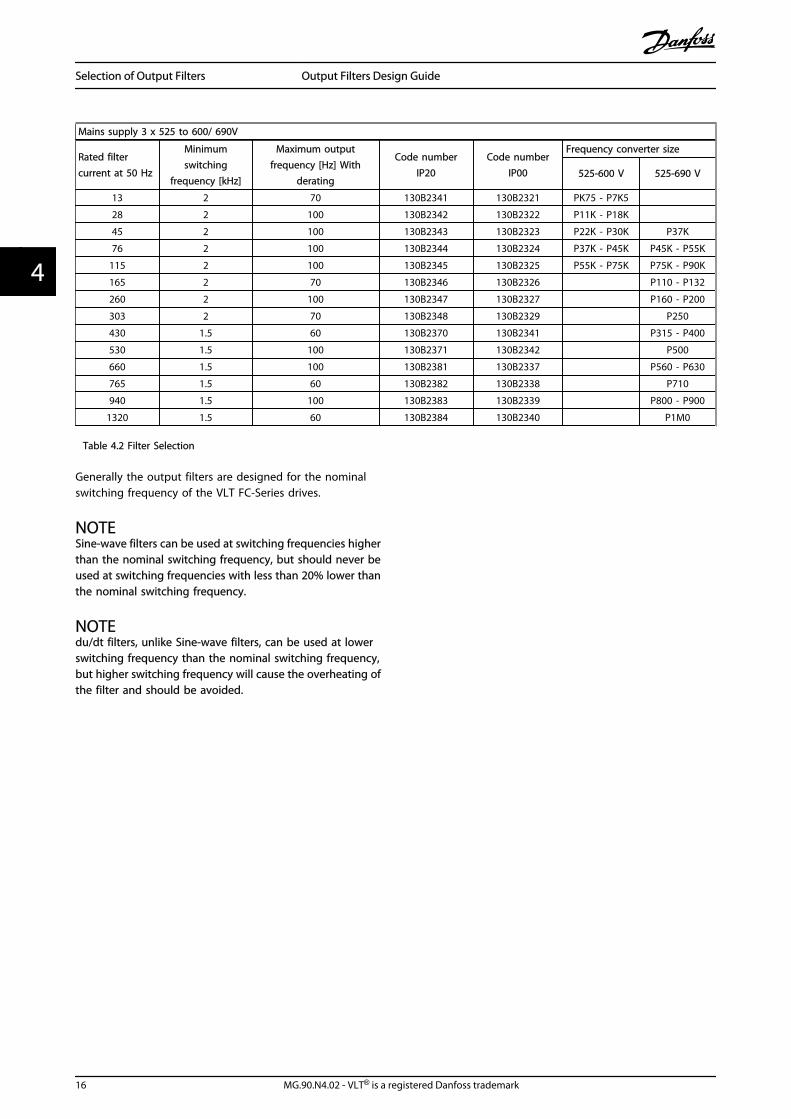
Mains supply 3 x 525 to 600/ 690V
Rated filtercurrent at 50 Hz
Minimumswitching
frequency [kHz]
Maximum outputfrequency [Hz] With
derating
Code numberIP20
Code numberIP00
Frequency converter size
525-600 V 525-690 V
13 2 70 130B2341 130B2321 PK75 - P7K5
28 2 100 130B2342 130B2322 P11K - P18K
45 2 100 130B2343 130B2323 P22K - P30K P37K
76 2 100 130B2344 130B2324 P37K - P45K P45K - P55K
115 2 100 130B2345 130B2325 P55K - P75K P75K - P90K
165 2 70 130B2346 130B2326 P110 - P132
260 2 100 130B2347 130B2327 P160 - P200
303 2 70 130B2348 130B2329 P250
430 1.5 60 130B2370 130B2341 P315 - P400
530 1.5 100 130B2371 130B2342 P500
660 1.5 100 130B2381 130B2337 P560 - P630
765 1.5 60 130B2382 130B2338 P710
940 1.5 100 130B2383 130B2339 P800 - P900
1320 1.5 60 130B2384 130B2340 P1M0
Table 4.2 Filter Selection
Generally the output filters are designed for the nominalswitching frequency of the VLT FC-Series drives.
NOTESine-wave filters can be used at switching frequencies higherthan the nominal switching frequency, but should never beused at switching frequencies with less than 20% lower thanthe nominal switching frequency.
NOTEdu/dt filters, unlike Sine-wave filters, can be used at lowerswitching frequency than the nominal switching frequency,but higher switching frequency will cause the overheating ofthe filter and should be avoided.
Selection of Output Filters Output Filters Design Guide
16 MG.90.N4.02 - VLT® is a registered Danfoss trademark
44
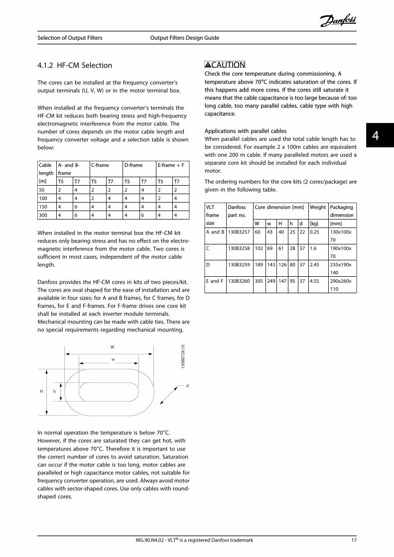
4.1.2 HF-CM Selection
The cores can be installed at the frequency converter’soutput terminals (U, V, W) or in the motor terminal box.
When installed at the frequency converter’s terminals theHF-CM kit reduces both bearing stress and high-frequencyelectromagnetic interference from the motor cable. Thenumber of cores depends on the motor cable length andfrequency converter voltage and a selection table is shownbelow:
Cablelength[m]
A- and B-frame
C-frame D-frame E-frame + F
T5 T7 T5 T7 T5 T7 T5 T7
50 2 4 2 2 2 4 2 2
100 4 4 2 4 4 4 2 4
150 4 6 4 4 4 4 4 4
300 4 6 4 4 4 6 4 4
When installed in the motor terminal box the HF-CM kitreduces only bearing stress and has no effect on the electro-magnetic interference from the motor cable. Two cores issufficient in most cases, independent of the motor cablelength.
Danfoss provides the HF-CM cores in kits of two pieces/kit.The cores are oval shaped for the ease of installation and areavailable in four sizes: for A and B frames, for C frames, for Dframes, for E and F-frames. For F-frame drives one core kitshall be installed at each inverter module terminals.Mechanical mounting can be made with cable ties. There areno special requirements regarding mechanical mounting.
W
w
H hd
130B
B728
.10
In normal operation the temperature is below 70°C.However, if the cores are saturated they can get hot, withtemperatures above 70°C. Therefore it is important to usethe correct number of cores to avoid saturation. Saturationcan occur if the motor cable is too long, motor cables areparalleled or high capacitance motor cables, not suitable forfrequency converter operation, are used. Always avoid motorcables with sector-shaped cores. Use only cables with round-shaped cores.
CAUTIONCheck the core temperature during commissioning. Atemperature above 70°C indicates saturation of the cores. Ifthis happens add more cores. If the cores still saturate itmeans that the cable capacitance is too large because of: toolong cable, too many parallel cables, cable type with highcapacitance.
Applications with parallel cablesWhen parallel cables are used the total cable length has tobe considered. For example 2 x 100m cables are equivalentwith one 200 m cable. If many paralleled motors are used aseparate core kit should be installed for each individualmotor.
The ordering numbers for the core kits (2 cores/package) aregiven in the following table.
VLTframesize
Danfosspart no.
Core dimension [mm] Weight Packagingdimension
W w H h d [kg] [mm]
A and B 130B3257 60 43 40 25 22 0.25 130x100x70
C 130B3258 102 69 61 28 37 1.6 190x100x70
D 130B3259 189 143 126 80 37 2.45 235x190x140
E and F 130B3260 305 249 147 95 37 4.55 290x260x110
Selection of Output Filters Output Filters Design Guide
MG.90.N4.02 - VLT® is a registered Danfoss trademark 17
4 4
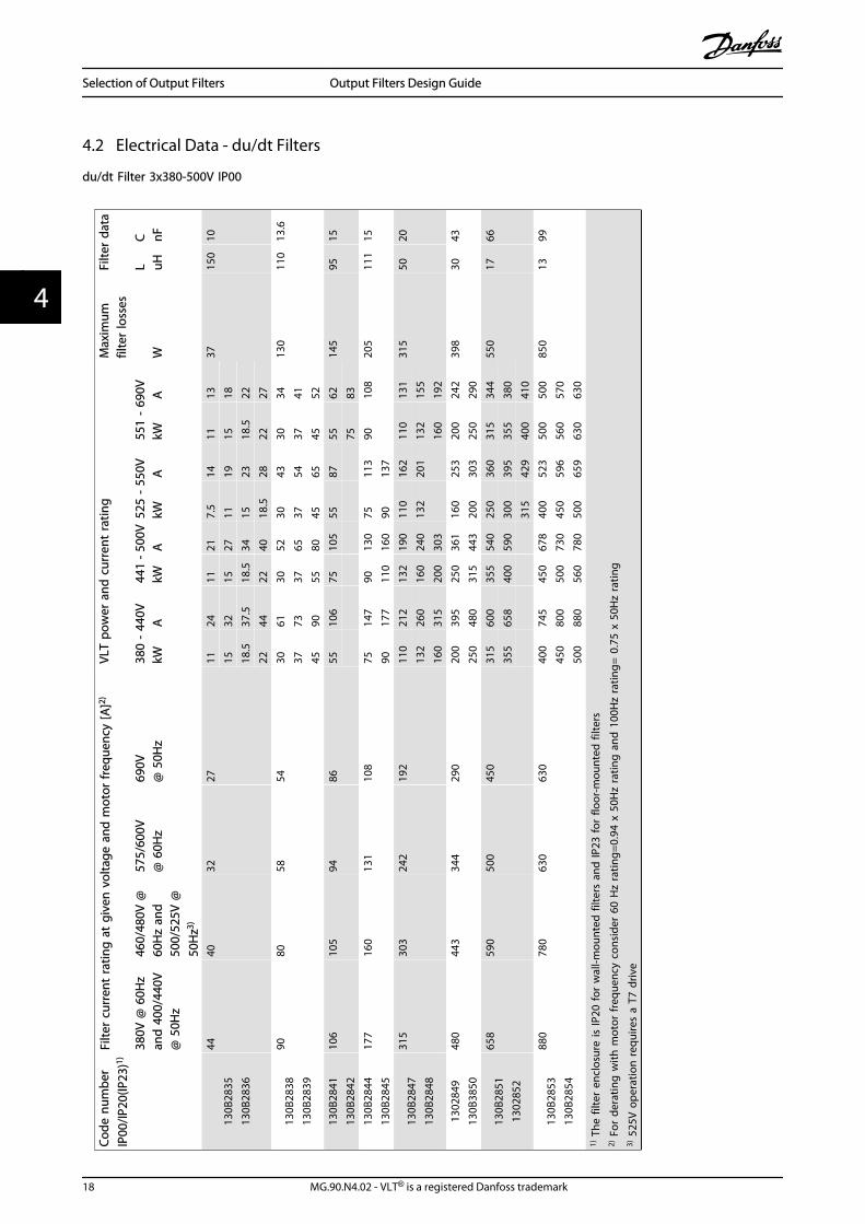
4.2 Electrical Data - du/dt Filters
du/dt Filter 3x380-500V IP00
Code
num
ber
IP00
/IP20
(IP23
)1)Fi
lter
curr
ent
ratin
g a
t gi
ven
vol
tage
and
mot
or fr
eque
ncy
[A]2)
VLT
pow
er a
nd c
urre
nt ra
ting
Max
imum
filte
r lo
sses
Filte
r da
ta
38
0V @
60H
zan
d 4
00/4
40V
@ 5
0Hz
460/
480V
@60
Hz
and
500/
525V
@50
Hz3)
575/
600V
@ 6
0Hz
690V
@ 5
0Hz
380
- 44
0V44
1 - 5
00V
525
- 55
0V55
1 -
690V
L
CkW
AkW
AkW
AkW
AW
uHnF
130B
2835
130B
2836
4440
3227
1124
1121
7.5
1411
1337
150
1015
3215
2711
1915
1818
.537
.518
.534
1523
18.5
2222
4422
4018
.528
2227
130B
2838
130B
2839
9080
5854
3061
3052
3043
3034
130
110
13.6
3773
3765
3754
3741
4590
5580
4565
4552
130B
2841
130B
2842
106
105
9486
5510
675
105
5587
5562
145
9515
7583
130B
2844
130B
2845
177
160
131
108
7514
790
130
7511
390
108
205
111
1590
177
110
160
9013
7
130B
2847
130B
2848
315
303
242
192
110
212
132
190
110
162
110
131
315
5020
132
260
160
240
132
201
132
155
160
315
200
303
160
192
1302
849
130B
3850
480
443
344
290
200
395
250
361
160
253
200
242
398
3043
250
480
315
443
200
303
250
290
130B
2851
1302
852
658
590
500
450
315
600
355
540
250
360
315
344
550
1766
355
658
400
590
300
395
355
380
315
429
400
410
130B
2853
130B
2854
880
780
630
630
400
745
450
678
400
523
500
500
850
1399
450
800
500
730
450
596
560
570
500
880
560
780
500
659
630
630
1) T
he fi
lter
encl
osur
e is
IP20
for
wal
l-mou
nted
filte
rs a
nd IP
23 fo
r flo
or-m
ount
ed fi
lters
2) F
or d
erat
ing
with
mot
or fr
eque
ncy
cons
ider
60
Hz
ratin
g=0.
94 x
50H
z ra
ting
and
100
Hz
ratin
g= 0
.75
x 50
Hz
ratin
g3)
525
V o
pera
tion
requ
ires
a T7
driv
e
Selection of Output Filters Output Filters Design Guide
18 MG.90.N4.02 - VLT® is a registered Danfoss trademark
44

Code
num
ber
IP00
/IP20
(IP23
)1Fi
lter
curr
ent
ratin
g a
t gi
ven
vol
tage
and
mot
or fr
eque
ncy
[A]2
VLT
pow
er a
nd c
urre
nt s
ize
Max
imum
filte
r lo
sses
Filte
r da
ta
38
0V @
60H
zan
d 4
00/4
40V
@ 5
0Hz
460/
480V
@60
Hz
and
500/
525V
@50
Hz3
575/
600V
@ 6
0Hz
690V
@ 5
0Hz
380
- 44
0V44
1 - 5
00V
525
- 55
0V55
1 -
690V
L
CkW
AkW
AkW
AkW
AW
uHnF
2 x
130B
2851
2 x
1302
852
or3
x 13
0B28
493
x 13
0B38
50
For
F-fr
ame
driv
es, p
aral
lel f
ilter
s sh
all b
e us
ed, o
ne fi
lter
for
each
inve
rter
mod
ule.
710
1260
800
1160
750
988
2 x
130B
2853
2 x
130B
2854
or3
x 13
0B28
513
x 13
0B28
52
900
945
3 x
130B
2853
3 x
130B
2854
800
1460
1000
1380
850
1108
1000
1060
1000
1700
1100
1530
1000
1317
1200
1260
2 x
130B
2849
2 x
130B
2852
450
800
500
730
500
659
500
880
560
780
1) T
he fi
lter
encl
osur
e is
IP20
for
wal
l-mou
nted
filte
rs a
nd IP
23 fo
r flo
or-m
ount
ed fi
lters
2) F
or d
erat
ing
with
mot
or fr
eque
ncy
cons
ider
60H
z ra
ting=
0.94
x 5
0Hz
ratin
g a
nd 1
00H
z ra
ting=
0.7
5 x
50H
z ra
ting
3) 5
25V
ope
ratio
n re
quire
s a
T7 d
rive
Selection of Output Filters Output Filters Design Guide
MG.90.N4.02 - VLT® is a registered Danfoss trademark 19
4 4
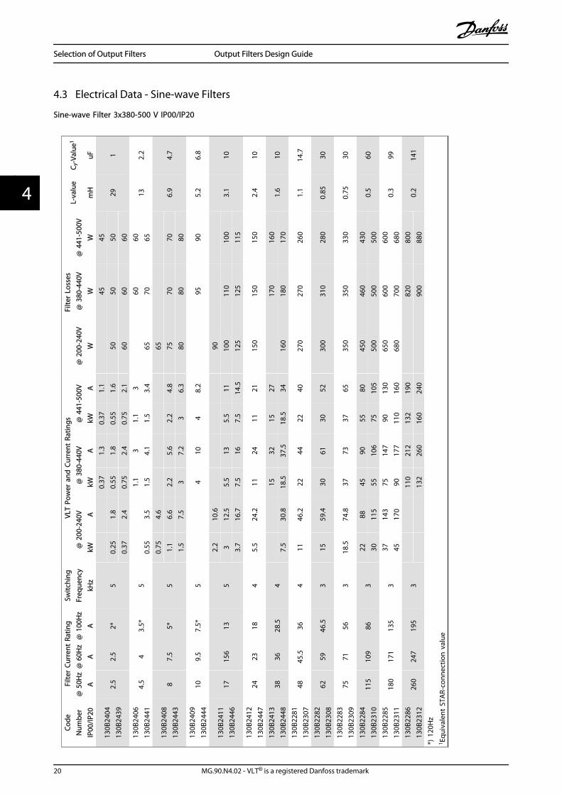
4.3 Electrical Data - Sine-wave Filters
Sine-wave Filter 3x380-500 V IP00/IP20
Code
Num
ber
IP00
/IP20
Filte
r Cu
rren
t Ra
ting
Switc
hing
Freq
uenc
yVL
T Po
wer
and
Cur
rent
Rat
ings
Filte
r Lo
sses
L-va
lue
C y-V
alue
1
@ 5
0Hz
@ 6
0Hz
@ 1
00H
z@
200
-240
V@
380
-440
V@
441
-500
V@
200
-240
V@
380
-440
V@
441
-500
VA
AA
kHz
kWA
kWA
kWA
WW
Wm
HuF
130B
2404
130B
2439
2.5
2.5
2*5
0.37
1.3
0.37
1.1
4545
291
0.25
1.8
0.55
1.8
0.55
1.6
5050
500.
372.
40.
752.
40.
752.
160
6060
130B
2406
130B
2441
4.5
43.
5*5
1.1
31.
13
6060
132.
20.
553.
51.
54.
11.
53.
465
7065
130B
2408
130B
2443
87.
55*
50.
754.
665
6.9
4.7
1.1
6.6
2.2
5.6
2.2
4.8
7570
701.
57.
53
7.2
36.
380
8080
130B
2409
130B
2444
109.
57.
5*5
410
48.
295
905.
26.
8
130B
2411
130B
2446
1715
613
52.
210
.690
3.1
103
12.5
5.5
135.
511
100
110
100
3.7
16.7
7.5
167.
514
.512
512
511
513
0B24
1213
0B24
4724
2318
45.
524
.211
2411
2115
015
015
02.
410
130B
2413
130B
2448
3836
28.5
415
3215
2717
016
01.
610
7.5
30.8
18.5
37.5
18.5
3416
018
017
013
0B22
8113
0B23
0748
45.5
364
1146
.222
4422
4027
027
026
01.
114
.7
130B
2282
130B
2308
6259
46.5
315
59.4
3061
3052
300
310
280
0.85
30
130B
2283
130B
2309
7571
563
18.5
74.8
3773
3765
350
350
330
0.75
30
130B
2284
130B
2310
115
109
863
2288
4590
5580
450
460
430
0.5
6030
115
5510
675
105
500
500
500
130B
2285
130B
2311
180
171
135
337
143
7514
790
130
650
600
600
0.3
9945
170
9017
711
016
068
070
068
013
0B22
8613
0B23
1226
024
719
53
110
212
132
190
820
800
0.2
141
132
260
160
240
900
880
*) 1
20H
z1 Eq
uiva
lent
STA
R-co
nnec
tion
val
ue
Selection of Output Filters Output Filters Design Guide
20 MG.90.N4.02 - VLT® is a registered Danfoss trademark
44
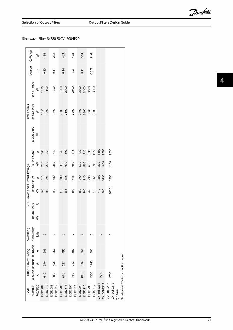
Sine-wave Filter 3x380-500V IP00/IP20
Code
Num
ber
IP00
/IP20
Filte
r Cu
rren
t Ra
ting
Switc
hing
Freq
uenc
yVL
T Po
wer
and
Cur
rent
Rat
ings
Filte
r Lo
sses
L-va
lue
C y-V
alue
1
@ 5
0Hz
@ 6
0Hz
@ 1
00H
z@
200
-240
V@
380
-440
V@
441
-500
V@
200
-240
V@
380
-440
V@
441
-500
VA
AA
kHz
kWA
kWA
kWA
WW
Wm
HuF
130B
2287
130B
2313
410
390
308
316
031
520
030
310
5010
500.
1319
820
039
525
036
112
0011
0013
0B22
8813
0B23
1448
045
636
03
250
480
315
443
1400
1350
0.11
282
130B
2289
130B
2315
660
627
495
331
560
035
554
020
0019
000.
1442
335
565
840
059
021
0020
0013
0B22
9013
0B23
1675
071
256
22
400
745
450
678
2900
2800
0..2
495
130B
2291
130B
2317
880
836
660
245
080
050
073
034
0033
000.
1156
450
088
056
078
036
0034
0013
0B22
9213
0B23
1712
0011
4090
02
560
990
630
890
3600
3600
0.07
584
663
011
2071
010
5038
0038
002x
130B
2291
2X13
0B23
1715
002
710
1260
800
1160
800
1460
1000
1380
2x13
0B22
922X
130B
2318
1700
210
0017
0011
0015
30
*) 1
20H
z1 Eq
uiva
lent
STA
R-co
nnec
tion
val
ue
Selection of Output Filters Output Filters Design Guide
MG.90.N4.02 - VLT® is a registered Danfoss trademark 21
4 4

Sine-wave Filter 3x525-690V IP00/IP20
Code
Num
ber
IP00
/IP20
Filte
r Cu
rren
t Ra
ting
Switc
hing
Freq
uenc
y
VLT
Pow
er a
nd C
urre
nt R
atin
gsFi
lter
loss
esL-
valu
eC y
-Val
ue1
@ 5
0Hz
@ 6
0Hz
@10
0Hz
@ 5
25-5
50V
@ 5
25-6
00V
@ 6
90V
@ 5
25-5
50V
@ 5
25-6
00V
@ 6
90V
AA
AkH
zkW
AkW
AkW
AW
WW
mH
uF
130B
2321
130B
2341
1312
.35
9.75
2
0.75
1.7
120
11.7
47
1.1
2.4
125
1.5
2.7
125
2.2
4.1
130
35.
213
04
6.4
140
5.5
9.5
160
7.5
11.5
170
130B
2322
130B
2342
2826
.521
2
1113
180
5.5
1011
1815
1823
023
015
2218
.522
250
250
18.5
2722
2728
028
013
0B23
2313
0B23
4345
42.5
33.5
222
3430
3430
030
03.
420
3041
3046
3746
360
330
360
130B
2324
130B
2344
7672
572
3752
3756
4554
450
420
450
233
4562
4576
5573
500
450
500
130B
2325
130B
2345
115
109
862
5583
5590
7586
800
750
750
1.3
4775
100
7511
390
108
850
800
850
130B
2326
130B
2346
165
157
123
290
131
9013
711
013
110
5010
0010
000.
966
110
155
110
162
132
155
1150
1100
1100
130B
2327
130B
2347
260
247
195
215
019
213
220
116
019
211
0010
5010
500.
694
180
242
160
253
200
242
1250
1200
1200
130B
2329
130B
2348
303
287
227
222
029
020
030
325
029
016
0016
0016
000.
513
6
1 Equi
vale
nt S
TAR-
conn
ectio
n v
alue
Selection of Output Filters Output Filters Design Guide
22 MG.90.N4.02 - VLT® is a registered Danfoss trademark
44
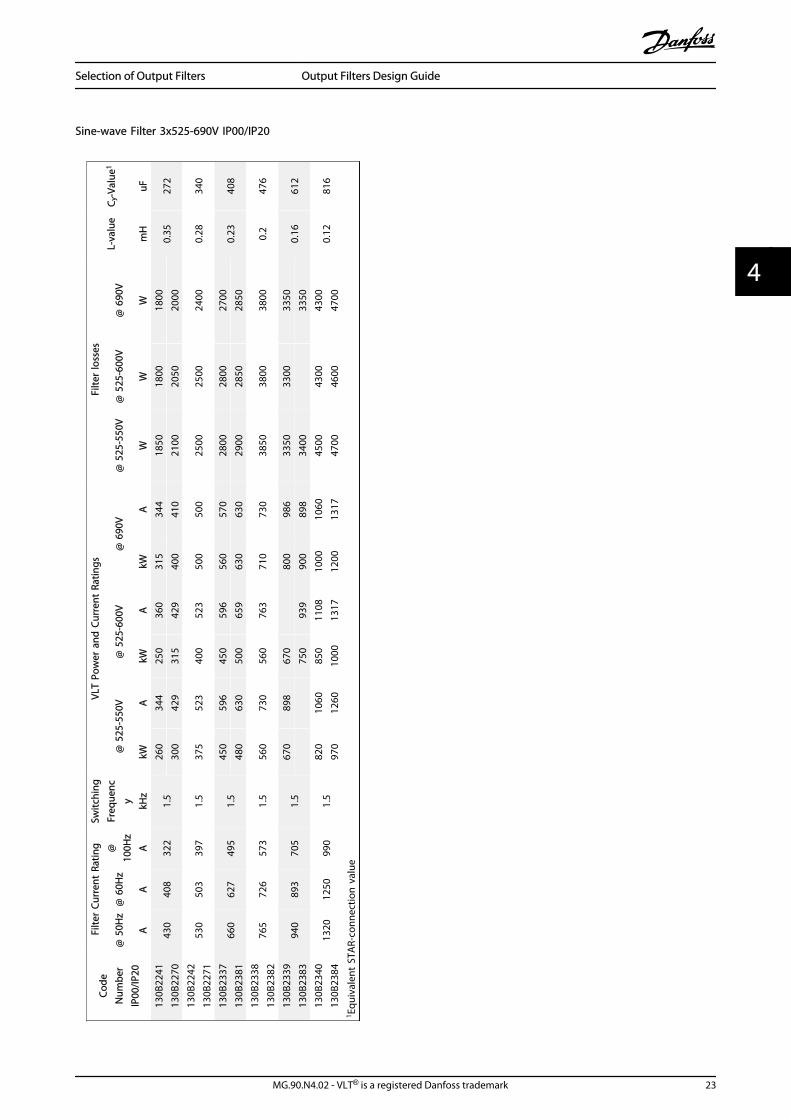
Sine-wave Filter 3x525-690V IP00/IP20
Code
Num
ber
IP00
/IP20
Filte
r Cu
rren
t Ra
ting
Switc
hing
Freq
uenc
y
VLT
Pow
er a
nd C
urre
nt R
atin
gsFi
lter
loss
esL-
valu
eC y
-Val
ue1
@ 5
0Hz
@ 6
0Hz
@10
0Hz
@ 5
25-5
50V
@ 5
25-6
00V
@ 6
90V
@ 5
25-5
50V
@ 5
25-6
00V
@ 6
90V
AA
AkH
zkW
AkW
AkW
AW
WW
mH
uF13
0B22
4113
0B22
7043
040
832
21.
526
034
425
036
031
534
418
5018
0018
000.
3527
230
042
931
542
940
041
021
0020
5020
0013
0B22
4213
0B22
7153
050
339
71.
537
552
340
052
350
050
025
0025
0024
000.
2834
0
130B
2337
130B
2381
660
627
495
1.5
450
596
450
596
560
570
2800
2800
2700
0.23
408
480
630
500
659
630
630
2900
2850
2850
130B
2338
130B
2382
765
726
573
1.5
560
730
560
763
710
730
3850
3800
3800
0.2
476
130B
2339
130B
2383
940
893
705
1.5
670
898
670
800
986
3350
3300
3350
0.16
612
750
939
900
898
3400
3350
130B
2340
130B
2384
1320
1250
990
1.5
820
1060
850
1108
1000
1060
4500
4300
4300
0.12
816
970
1260
1000
1317
1200
1317
4700
4600
4700
1 Equi
vale
nt S
TAR-
conn
ectio
n v
alue
Selection of Output Filters Output Filters Design Guide
MG.90.N4.02 - VLT® is a registered Danfoss trademark 23
4 4
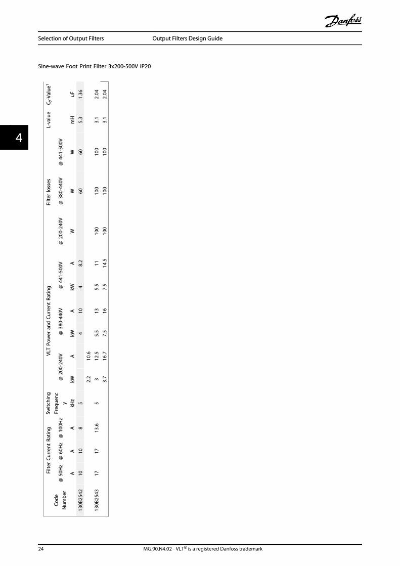
Sine-wave Foot Print Filter 3x200-500V IP20
Code
Num
ber
Filte
r Cu
rren
t Ra
ting
Switc
hing
Freq
uenc
y
VLT
Pow
er a
nd C
urre
nt R
atin
gFi
lter
loss
esL-
valu
eC y
-Val
ue1
@ 5
0Hz
@ 6
0Hz
@ 1
00H
z@
200
-240
V@
380
-440
V@
441
-500
V@
200
-240
V@
380
-440
V@
441
-500
V
AA
AkH
zkW
AkW
AkW
AW
WW
mH
uF13
0B25
4210
108
54
104
8.2
6060
5.3
1.36
130B
2543
1717
13.6
52.
210
.63
12.5
5.5
135.
511
100
100
100
3.1
2.04
3.7
16.7
7.5
167.
514
.510
010
010
03.
12.
04
Selection of Output Filters Output Filters Design Guide
24 MG.90.N4.02 - VLT® is a registered Danfoss trademark
44
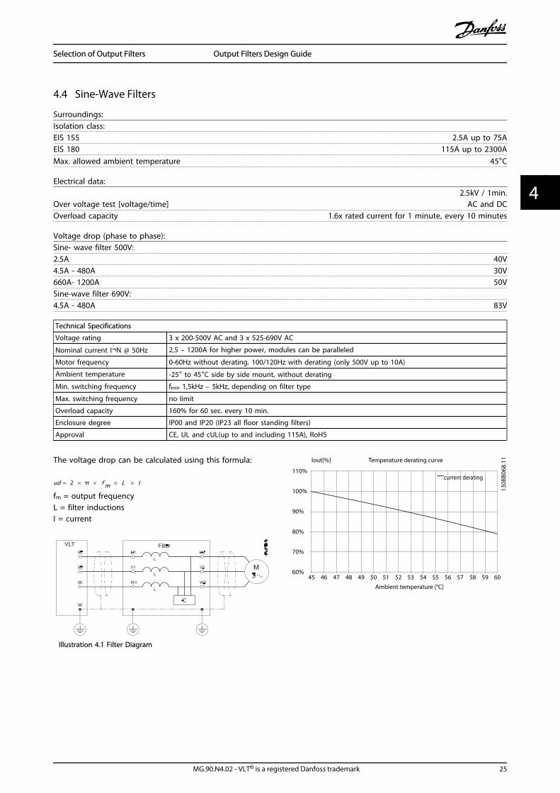
4.4 Sine-Wave Filters
Surroundings:Isolation class:EIS 155 2.5A up to 75AEIS 180 115A up to 2300AMax. allowed ambient temperature 45°C
Electrical data:
Over voltage test [voltage/time]2.5kV / 1min.
AC and DCOverload capacity 1.6x rated current for 1 minute, every 10 minutes
Voltage drop (phase to phase):Sine- wave filter 500V:2.5A 40V4.5A - 480A 30V660A- 1200A 50VSine-wave filter 690V:4.5A - 480A 83V
Technical Specifications
Voltage rating 3 x 200-500V AC and 3 x 525-690V AC
Nominal current I¬N @ 50Hz 2,5 – 1200A for higher power, modules can be paralleled
Motor frequency 0-60Hz without derating. 100/120Hz with derating (only 500V up to 10A)
Ambient temperature -25° to 45°C side by side mount, without derating
Min. switching frequency fmin 1,5kHz – 5kHz, depending on filter type
Max. switching frequency no limit
Overload capacity 160% for 60 sec. every 10 min.
Enclosure degree IP00 and IP20 (IP23 all floor standing filters)
Approval CE, UL and cUL(up to and including 115A), RoHS
The voltage drop can be calculated using this formula:
ud = 2 × π × f m × L × I
fm = output frequencyL = filter inductionsI = current
Illustration 4.1 Filter Diagram
T emper a tur e der a ting cur v e lout[%]
110%
100%
90%
80%
70%
60% 45 46 47 48 49 50 51 52 53 54 55 56 57 58 59 60
Ambien t t emper a tur e [ º C]
cur r en t der a ting
130B
B068
.11
Selection of Output Filters Output Filters Design Guide
MG.90.N4.02 - VLT® is a registered Danfoss trademark 25
4 4
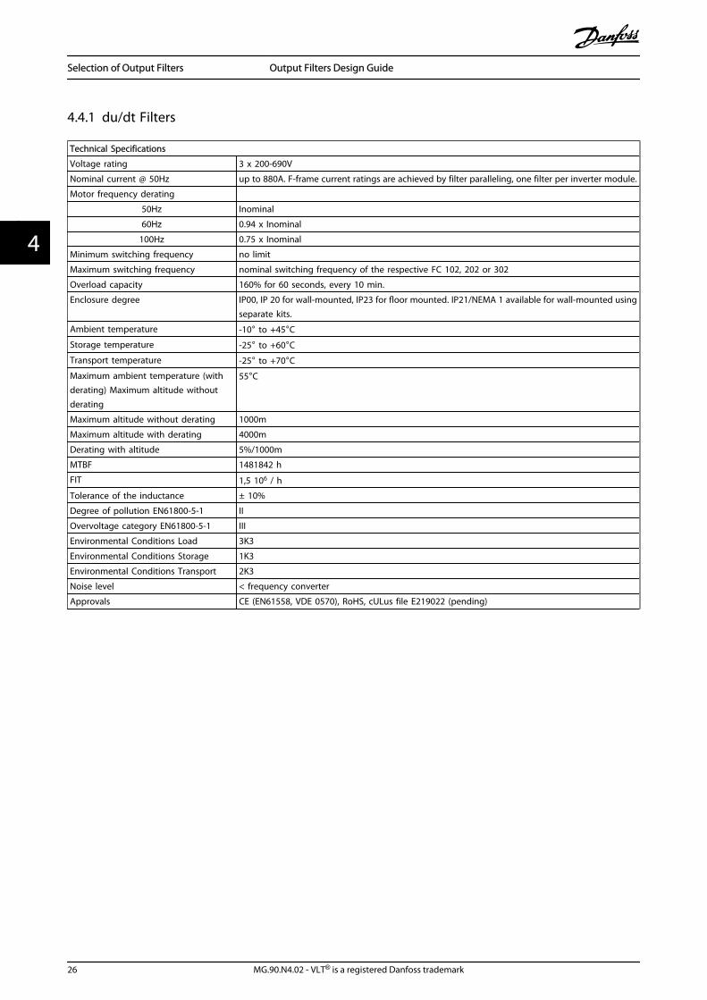
4.4.1 du/dt Filters
Technical Specifications
Voltage rating 3 x 200-690V
Nominal current @ 50Hz up to 880A. F-frame current ratings are achieved by filter paralleling, one filter per inverter module.
Motor frequency derating
50Hz Inominal
60Hz 0.94 x Inominal
100Hz 0.75 x Inominal
Minimum switching frequency no limit
Maximum switching frequency nominal switching frequency of the respective FC 102, 202 or 302
Overload capacity 160% for 60 seconds, every 10 min.
Enclosure degree IP00, IP 20 for wall-mounted, IP23 for floor mounted. IP21/NEMA 1 available for wall-mounted usingseparate kits.
Ambient temperature -10° to +45°CStorage temperature -25° to +60°CTransport temperature -25° to +70°CMaximum ambient temperature (withderating) Maximum altitude withoutderating
55°C
Maximum altitude without derating 1000m
Maximum altitude with derating 4000m
Derating with altitude 5%/1000m
MTBF 1481842 h
FIT 1,5 106 / h
Tolerance of the inductance ± 10%
Degree of pollution EN61800-5-1 II
Overvoltage category EN61800-5-1 III
Environmental Conditions Load 3K3
Environmental Conditions Storage 1K3
Environmental Conditions Transport 2K3
Noise level < frequency converter
Approvals CE (EN61558, VDE 0570), RoHS, cULus file E219022 (pending)
Selection of Output Filters Output Filters Design Guide
26 MG.90.N4.02 - VLT® is a registered Danfoss trademark
44
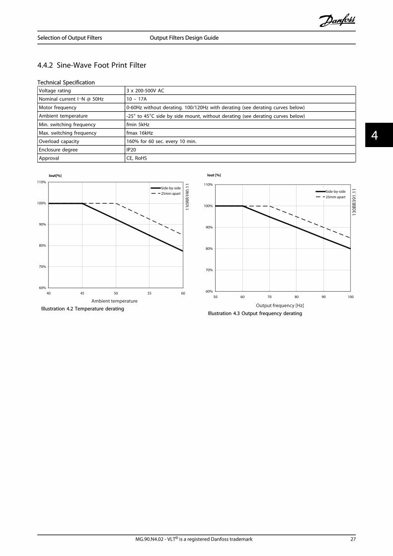
4.4.2 Sine-Wave Foot Print Filter
Technical SpecificationVoltage rating 3 x 200-500V AC
Nominal current I¬N @ 50Hz 10 – 17A
Motor frequency 0-60Hz without derating. 100/120Hz with derating (see derating curves below)
Ambient temperature -25° to 45°C side by side mount, without derating (see derating curves below)
Min. switching frequency fmin 5kHz
Max. switching frequency fmax 16kHz
Overload capacity 160% for 60 sec. every 10 min.
Enclosure degree IP20
Approval CE, RoHS
Illustration 4.2 Temperature deratingIllustration 4.3 Output frequency derating
Selection of Output Filters Output Filters Design Guide
MG.90.N4.02 - VLT® is a registered Danfoss trademark 27
4 4
5 How to Install
5.1 Mechanical Mounting
5.1.1 Safety Requirements for MechanicalInstallation
WARNINGPay attention to the requirements that apply to integrationand field mounting kit. Observe the information in the list toavoid serious damage or injury, especially when installinglarge units.
The filter is cooled by natural convection.To protect the unit from overheating it must be ensured thatthe ambient temperature does not exceed the maximumtemperature stated for the filter. Locate the maximumtemperature in the paragraph Derating for AmbientTemperature.If the ambient temperature is in the range of 45°C - 55°C,derating of the filter will become relevant.
5.1.2 Mounting
• All wall mounted filters must be mounted verticallywith the terminals at the bottom.
• Do not mount the filter close to other heatingelements or heat sensitive material (such as wood)
• The filter can be side-mounted with the frequencyconverter. There is no requirement for spacingbetween the filter and frequency converter.
• Top and bottom clearance is minimum 100mm(200mm for foot print filters).
• The surface temperature of IP20/23 units does notexceed 70°C.
• The surface temperature of IP00 filters can exceed70°C and a hot surface warning label is placed onthe filter.
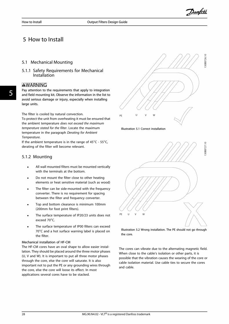
Mechanical installation of HF-CMThe HF-CM cores have an oval shape to allow easier instal-lation. They should be placed around the three motor phases(U, V and W). It is important to put all three motor phasesthrough the core, else the core will saturate. It is alsoimportant not to put the PE or any grounding wires throughthe core, else the core will loose its effect. In mostapplications several cores have to be stacked.
PE U V W
130B
B726
.10
Illustration 5.1 Correct installation
PE U V W
130B
B727
.10
Illustration 5.2 Wrong installation. The PE should not go throughthe core.
The cores can vibrate due to the alternating magnetic field.When close to the cable’s isolation or other parts, it ispossible that the vibration causes the wearing of the core orcable isolation material. Use cable ties to secure the coresand cable.
How to Install Output Filters Design Guide
28 MG.90.N4.02 - VLT® is a registered Danfoss trademark
55
5.1.3 Earthing
The filter must be earthed before switching the power on(high leakage currents).Common mode interferences are kept small by ensuring thatthe current return path to the VLT has the lowest possibleimpedance.
• Choose the best earthing possibility (e.g. cabinetmounting panel)
• Use the enclosed (in accessory bag) protectiveearth terminal to ensure the best possible earthing
• Remove any paint present to ensure good electricalcontact
• Ensure that the filter and frequency converter makesolid electrical contact (high frequency earthing)
• The filter must be earthed before switching thepower on (high leakage currents)
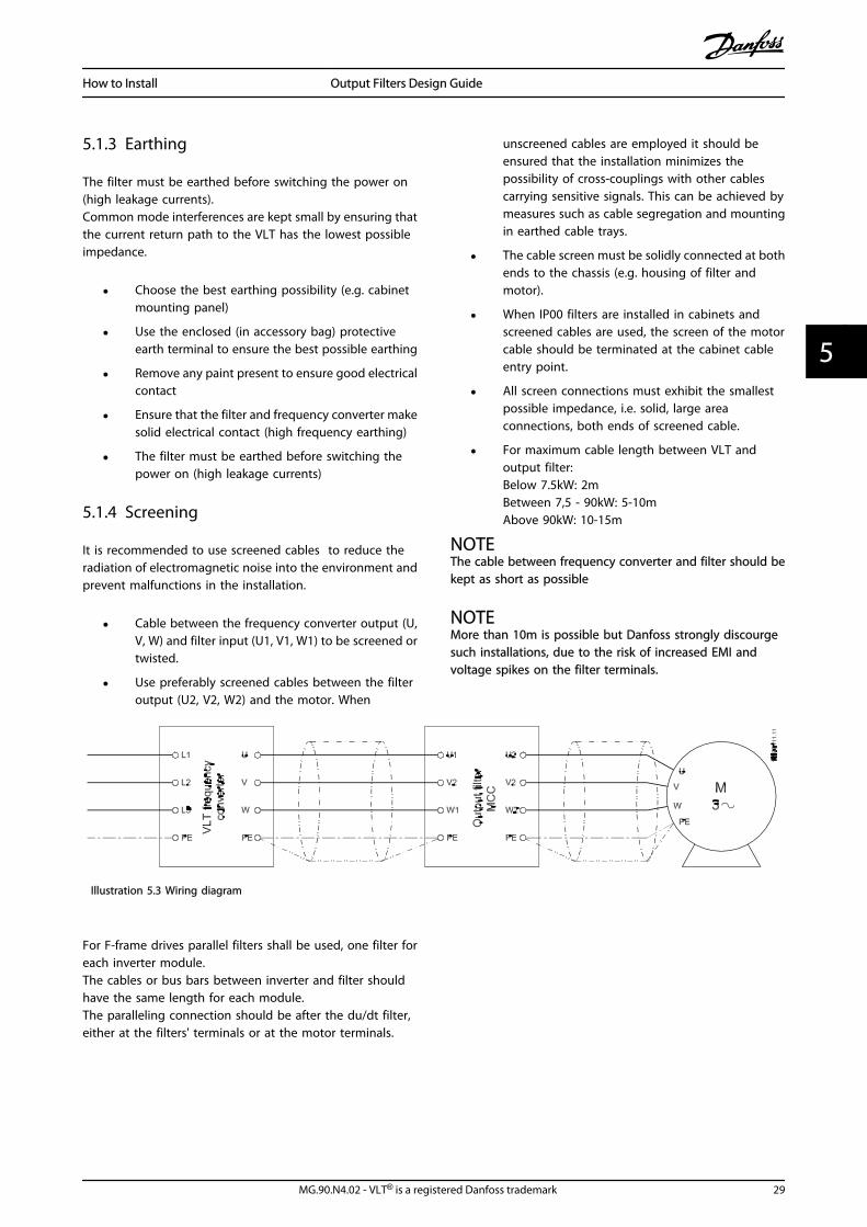
5.1.4 Screening
It is recommended to use screened cables to reduce theradiation of electromagnetic noise into the environment andprevent malfunctions in the installation.
• Cable between the frequency converter output (U,V, W) and filter input (U1, V1, W1) to be screened ortwisted.
• Use preferably screened cables between the filteroutput (U2, V2, W2) and the motor. When
unscreened cables are employed it should beensured that the installation minimizes thepossibility of cross-couplings with other cablescarrying sensitive signals. This can be achieved bymeasures such as cable segregation and mountingin earthed cable trays.
• The cable screen must be solidly connected at bothends to the chassis (e.g. housing of filter andmotor).
• When IP00 filters are installed in cabinets andscreened cables are used, the screen of the motorcable should be terminated at the cabinet cableentry point.
• All screen connections must exhibit the smallestpossible impedance, i.e. solid, large areaconnections, both ends of screened cable.
• For maximum cable length between VLT andoutput filter:Below 7.5kW: 2mBetween 7,5 - 90kW: 5-10mAbove 90kW: 10-15m
NOTEThe cable between frequency converter and filter should bekept as short as possible
NOTEMore than 10m is possible but Danfoss strongly discourgesuch installations, due to the risk of increased EMI andvoltage spikes on the filter terminals.
Illustration 5.3 Wiring diagram
For F-frame drives parallel filters shall be used, one filter foreach inverter module.The cables or bus bars between inverter and filter shouldhave the same length for each module.The paralleling connection should be after the du/dt filter,either at the filters' terminals or at the motor terminals.
How to Install Output Filters Design Guide
MG.90.N4.02 - VLT® is a registered Danfoss trademark 29
5 5
5.2 Mechanical Dimensions
5.2.1 Sketches
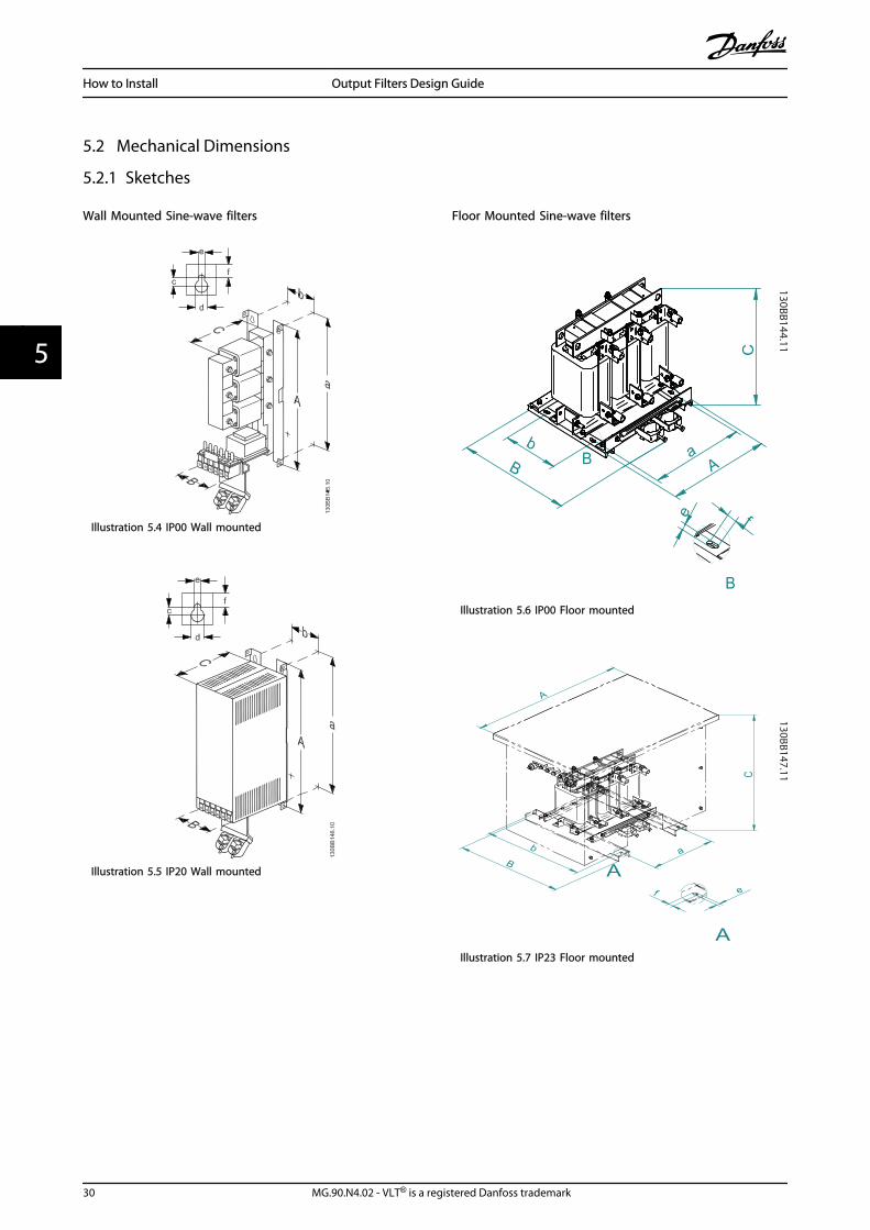
Wall Mounted Sine-wave filters
Illustration 5.4 IP00 Wall mounted
Illustration 5.5 IP20 Wall mounted
Floor Mounted Sine-wave filters
Illustration 5.6 IP00 Floor mounted
Illustration 5.7 IP23 Floor mounted
How to Install Output Filters Design Guide
30 MG.90.N4.02 - VLT® is a registered Danfoss trademark
55
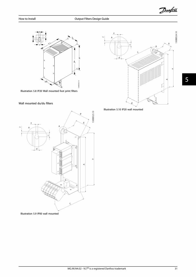
Illustration 5.8 IP20 Wall mounted foot print filters
Wall mounted du/du filters
a
b
A
C
B
c
e
d
f A A
130B
B523
.10
Illustration 5.9 IP00 wall mounted
b
a
A
C
B
e
f A
d
c
A
130B
B524
.10
Illustration 5.10 IP20 wall mounted
How to Install Output Filters Design Guide
MG.90.N4.02 - VLT® is a registered Danfoss trademark 31
5 5
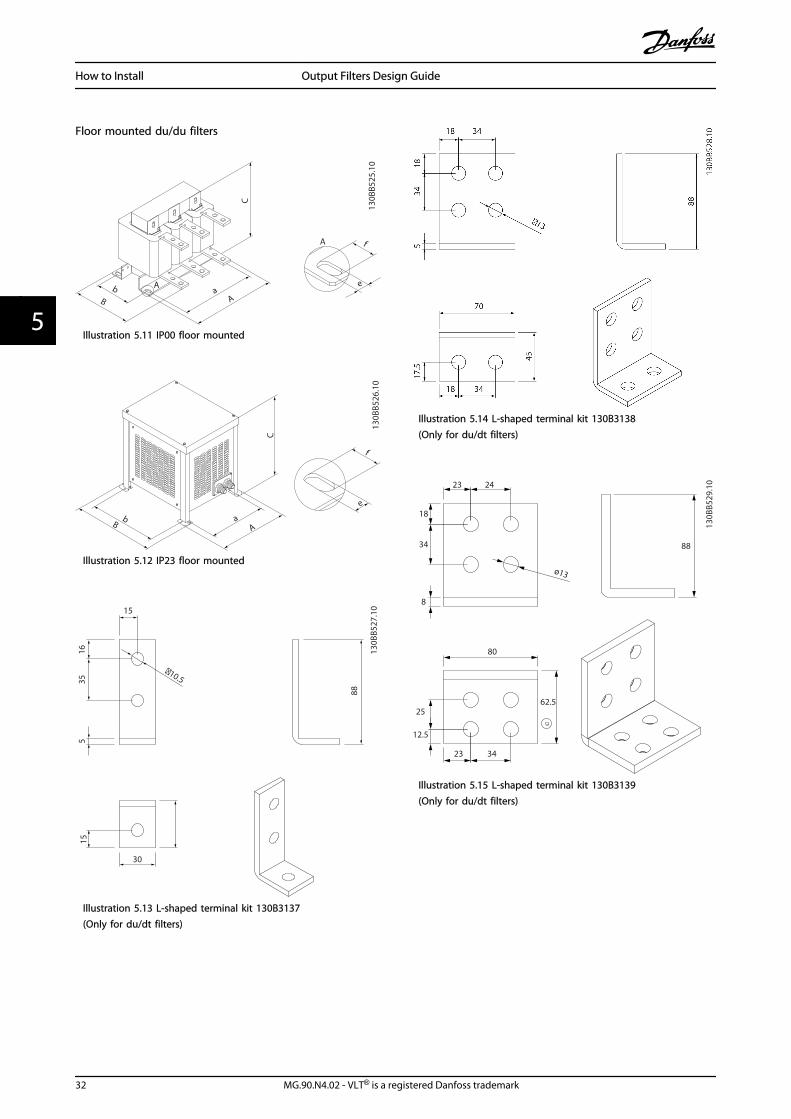
Floor mounted du/du filters
b B
a A
e
f C
A
A
130B
B525
.10
Illustration 5.11 IP00 floor mounted
C
B a
A b
f
e
130B
B526
.10
Illustration 5.12 IP23 floor mounted
30
88
516
35
15
�10.5
15
130B
B527
.10
Illustration 5.13 L-shaped terminal kit 130B3137(Only for du/dt filters)
Illustration 5.14 L-shaped terminal kit 130B3138(Only for du/dt filters)
23 24
18
34
8
ø13
88
80
25
12.5
23 34
62.513
0BB5
29.10
Illustration 5.15 L-shaped terminal kit 130B3139(Only for du/dt filters)
How to Install Output Filters Design Guide
32 MG.90.N4.02 - VLT® is a registered Danfoss trademark
55
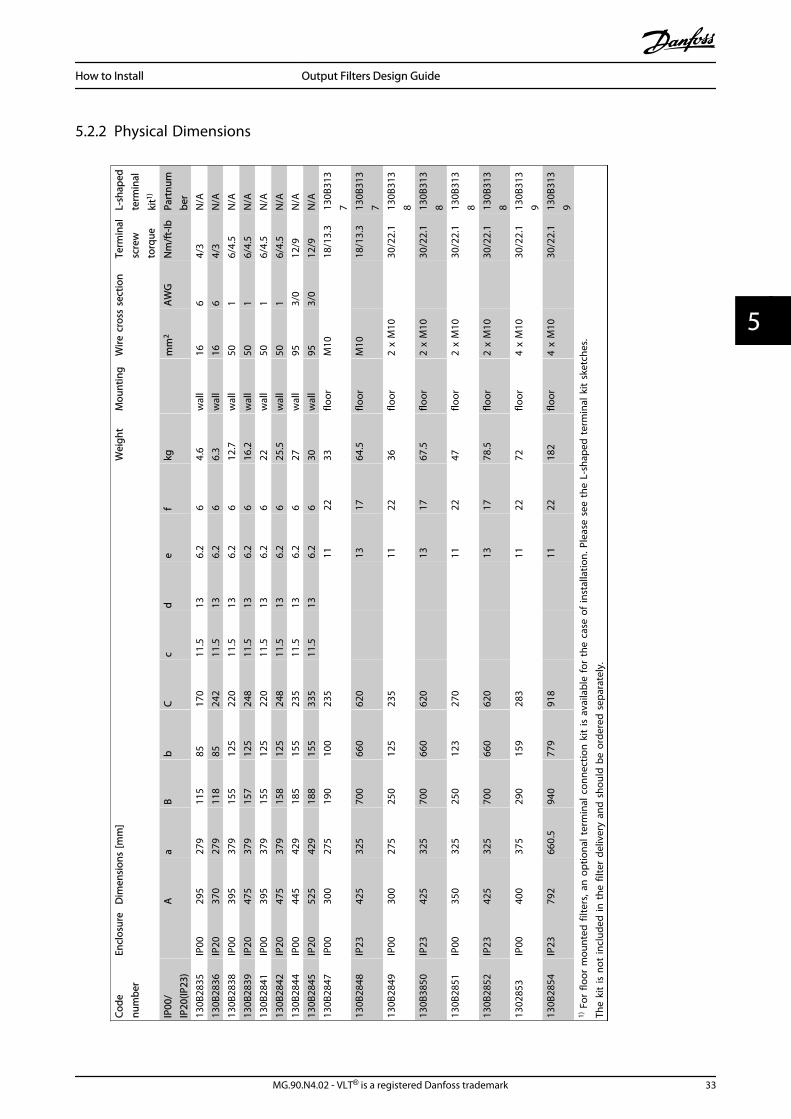
5.2.2 Physical DimensionsCo
denu
mbe
rEn
clos
ure
Dim
ensi
ons
[mm
]W
eigh
tM
ount
ing
Wire
cro
ss s
ectio
nTe
rmin
alsc
rew
torq
ue
L-sh
aped
term
inal
kit1)
IP00
/IP
20(IP
23)
A
aB
bC
cd
ef
kg
mm
2A
WG
Nm
/ft-
IbPa
rtnu
mbe
r13
0B28
35IP
0029
527
911
585
170
11.5
136.
26
4.6
wal
l16
64/
3N
/A13
0B28
36IP
2037
027
911
885
242
11.5
136.
26
6.3
wal
l16
64/
3N
/A13
0B28
38IP
0039
537
915
512
522
011
.513
6.2
612
.7w
all
501
6/4.
5N
/A13
0B28
39IP
2047
537
915
712
524
811
.513
6.2
616
.2w
all
501
6/4.
5N
/A13
0B28
41IP
0039
537
915
512
522
011
.513
6.2
622
wal
l50
16/
4.5
N/A
130B
2842
IP20
475
379
158
125
248
11.5
136.
26
25.5
wal
l50
16/
4.5
N/A
130B
2844
IP00
445
429
185
155
235
11.5
136.
26
27w
all
953/
012
/9N
/A13
0B28
45IP
2052
542
918
815
533
511
.513
6.2
630
wal
l95
3/0
12/9
N/A
130B
2847
IP00
300
275
190
100
235
1122
33flo
orM
10
18/1
3.3
130B
313
713
0B28
48IP
2342
532
570
066
062
0
13
1764
.5flo
orM
10
18/1
3.3
130B
313
713
0B28
49IP
0030
027
525
012
523
5
11
2236
floor
2 x
M10
30
/22.
113
0B31
38
130B
3850
IP23
425
325
700
660
620
1317
67.5
floor
2 x
M10
30
/22.
113
0B31
38
130B
2851
IP00
350
325
250
123
270
1122
47flo
or2
x M
10
30/2
2.1
130B
313
813
0B28
52IP
2342
532
570
066
062
0
13
1778
.5flo
or2
x M
10
30/2
2.1
130B
313
813
0285
3IP
0040
037
529
015
928
3
11
2272
floor
4 x
M10
30
/22.
113
0B31
39
130B
2854
IP23
792
660.
594
077
991
8
11
2218
2flo
or4
x M
10
30/2
2.1
130B
313
91)
For
floo
r m
ount
ed fi
lters
, an
opt
iona
l ter
min
al c
onne
ctio
n k
it is
ava
ilabl
e fo
r th
e ca
se o
f in
stal
latio
n. P
leas
e se
e th
e L-
shap
ed t
erm
inal
kit
ske
tche
s.Th
e ki
t is
not
incl
uded
in t
he fi
lter
deliv
ery
and
sho
uld
be
orde
red
sep
arat
ely.
How to Install Output Filters Design Guide
MG.90.N4.02 - VLT® is a registered Danfoss trademark 33
5 5
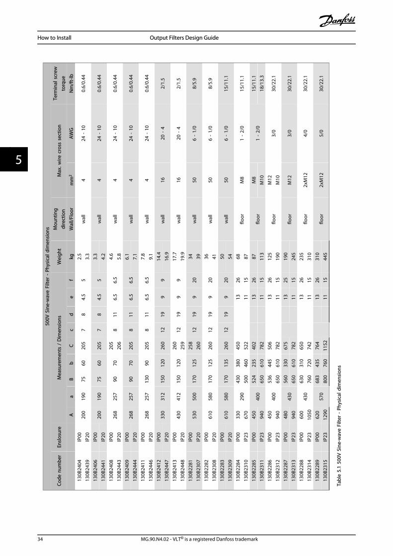
500V
Sin
e-w
ave
Filte
r -
Phys
ical
dim
ensi
ons
Code
num
ber
Ensl
osur
eM
easu
rem
ents
/ D
imen
sion
sW
eigh
tM
ount
ing
dire
ctio
nM
ax. w
ire c
ross
sec
tion
Term
inal
scr
ewto
rque
Aa
Bb
Cc
de
fkg
Wal
l/Flo
orm
m2
AW
GN
m/f
t-lb
130B
2404
IP00
200
190
7560
205
78
4.5
52.
5w
all
424
- 1
00.
6/0.
4413
0B24
39IP
203.
313
0B24
06IP
0020
019
075
6020
57
84.
55
3.3
wal
l4
24 -
10
0.6/
0.44
130B
2441
IP20
4.2
130B
2408
IP00
268
257
9070
205
811
6.5
6.5
4.6
wal
l4
24 -
10
0.6/
0.44
130B
2443
IP20
206
5.8
130B
2409
IP00
268
257
9070
205
811
6.5
6.5
6.1
wal
l4
24 -
10
0.6/
0.44
130B
2444
IP20
7.1
130B
2411
IP00
268
257
130
9020
58
116.
56.
57.
8w
all
424
- 1
00.
6/0.
4413
0B24
46IP
209.
113
0B24
12IP
0033
031
215
012
026
012
199
914
.4w
all
1620
- 4
2/1.
513
0B24
47IP
2016
.913
0B24
13IP
0043
041
215
012
026
012
199
917
.7w
all
1620
- 4
2/1.
513
0B24
48IP
2025
919
.913
0B22
81IP
0053
050
017
012
525
812
199
2034
wal
l50
6 -
1/0
8/5.
913
0B23
07IP
2026
039
130B
2282
IP00
610
580
170
125
260
1219
920
36w
all
506
- 1/
08/
5.9
130B
2308
IP20
4113
0B22
83IP
0061
058
017
013
526
012
199
2050
wal
l50
6 -
1/0
15/1
1.1
130B
2309
IP20
5413
0B22
84IP
0033
029
043
038
045
0
13
2668
floor
M8
1 -
2/0
15/1
1.1
130B
2310
IP23
670
500
460
522
11
1587
130B
2285
IP00
450
400
524
235
402
1326
87flo
orM
81
- 2/
015
/11.
113
0B23
11IP
2394
065
061
078
211
1511
3M
1018
/13.
313
0B22
86IP
0045
040
053
644
550
6
13
2612
5flo
orM
123/
030
/22.
113
0B23
12IP
2394
065
061
078
2
1115
190
M10
130B
2287
IP00
480
430
560
330
675
1325
190
floor
M12
3/0
30/2
2.1
130B
2313
IP23
940
650
610
782
1115
245
130B
2288
IP00
600
430
630
310
650
1326
235
floor
2xM
124/
030
/22.
113
0B23
14IP
2310
5076
072
074
2
11
1531
013
0B22
89IP
0062
057
068
343
576
413
2631
0flo
or2x
M12
5/0
30/2
2.1
130B
2315
IP23
1290
800
760
1152
1115
445
Tabl
e 5.
1 50
0V S
ine-
wav
e Fi
lter
- Ph
ysic
al d
imen
sion
s
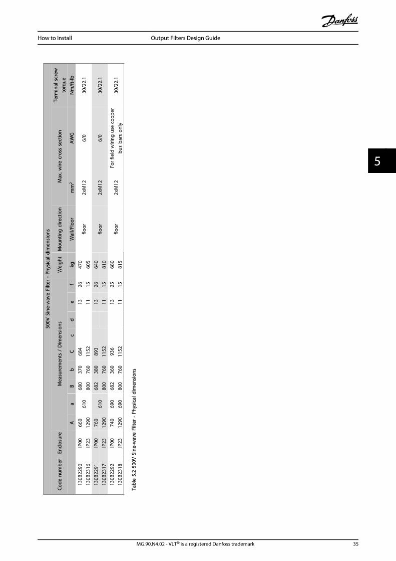
How to Install Output Filters Design Guide
34 MG.90.N4.02 - VLT® is a registered Danfoss trademark
55
500V
Sin
e-w
ave
Filte
r -
Phys
ical
dim
ensi
ons
Code
num
ber
Encl
osur
eM
easu
rem
ents
/ D
imen
sion
sW
eigh
tM
ount
ing
dire
ctio
nM
ax. w
ire c
ross
sec
tion
Term
inal
scr
ewto
rque
Aa
Bb
Cc
de
fkg
Wal
l/Flo
orm
m2
AW
GN
m/f
t-lb
130B
2290
IP00
660
610
680
370
684
1326
470
floor
2xM
126/
030
/22.
113
0B23
16IP
2312
9080
076
011
52
1115
605
130B
2291
IP00
760
610
682
380
893
1326
640
floor
2xM
126/
030
/22.
113
0B23
17IP
2312
9080
076
011
5211
1581
013
0B22
92IP
0074
069
068
236
093
6
13
2568
0flo
or2x
M12
For f
ield
wiri
ng u
se c
oope
rbu
s ba
rs o
nly
30/2
2.1
130B
2318
IP23
1290
690
800
760
1152
1115
815
Tabl
e 5.
2 50
0V S
ine-
wav
e Fi
lter
- Ph
ysic
al d
imen
sion
s
How to Install Output Filters Design Guide
MG.90.N4.02 - VLT® is a registered Danfoss trademark 35
5 5
690V
Sin
e-w
ave
filte
r -
Phys
ical
Dim
ensi
ons
Code
num
ber
Encl
osur
eM
easu
rem
ents
/ D
imen
sion
sW
eigh
tM
ount
ing
dire
ctio
nM
ax. w
ire c
ross
sec
tion
Term
inal
scr
ewto
rque
Aa
Bb
Cc
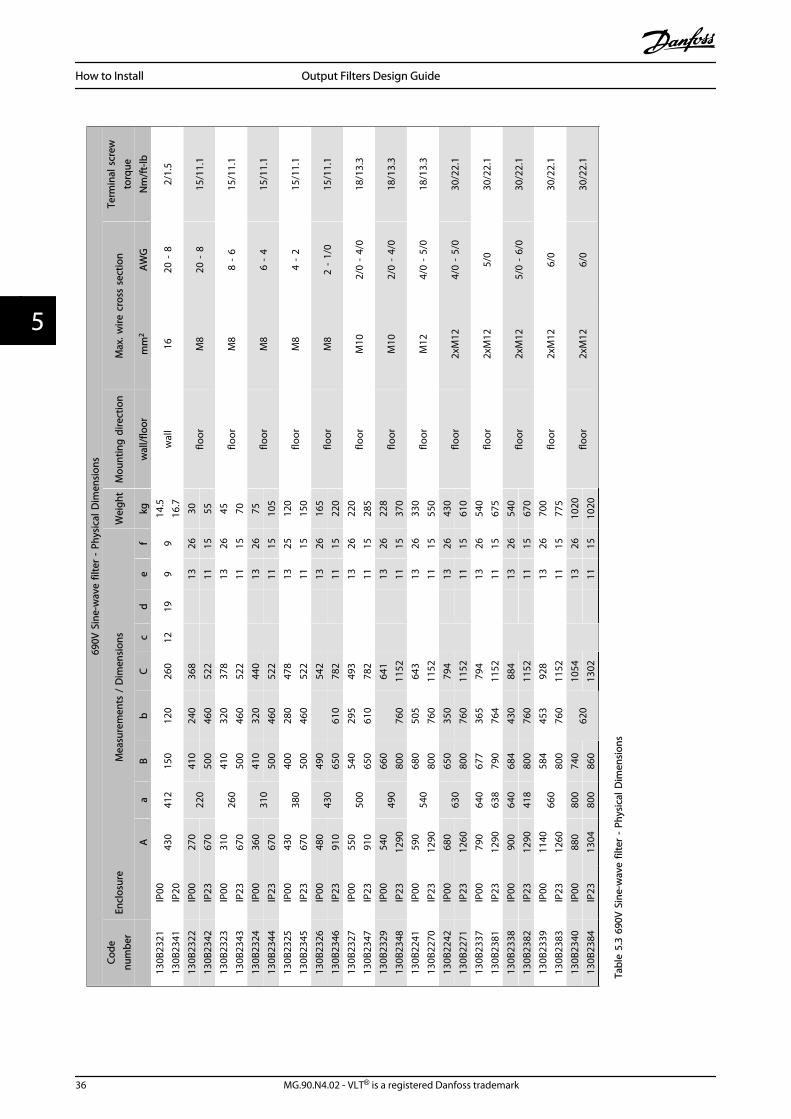
de
fkg
wal
l/flo
orm
m2
AW
GN
m/f
t-lb
130B
2321
IP00
430
412
150
120
260
1219
99
14.5
wal
l16
20 -
82/
1.5
130B
2341
IP20
16.7
130B
2322
IP00
270
220
410
240
368
1326
30flo
orM
820
- 8
15/1
1.1
130B
2342
IP23
670
500
460
522
1115
5513
0B23
23IP
0031
026
041
032
037
8
13
2645
floor
M8
8 -
615
/11.
113
0B23
43IP
2367
050
046
052
2
1115
7013
0B23
24IP
0036
031
041
032
044
013
2675
floor
M8
6 -
415
/11.
113
0B23
44IP
2367
050
046
052
211
1510
513
0B23
25IP
0043
038
040
028
047
8
13
2512
0flo
orM
84
- 2
15/1
1.1
130B
2345
IP23
670
500
460
522
11
1515
013
0B23
26IP
0048
043
049
054
213
2616
5flo
orM
82
- 1/
015
/11.
113
0B23
46IP
2391
065
061
078
211
1522
013
0B23
27IP
0055
050
054
029
549
3
13
2622
0flo
orM
102/
0 -
4/0
18/1
3.3
130B
2347
IP23
910
650
610
782
11
1528
513
0B23
29IP
0054
049
066
064
113
2622
8flo
orM
102/
0 -
4/0
18/1
3.3
130B
2348
IP23
1290
800
760
1152
1115
370
130B
2241
IP00
590
540
680
505
643
1326
330
floor
M12
4/0
- 5/
018
/13.
313
0B22
70IP
2312
9080
076
011
52
1115
550
130B
2242
IP00
680
630
650
350
794
1326
430
floor
2xM
124/
0 -
5/0
30/2
2.1
130B
2271
IP23
1260
800
760
1152
1115
610
130B
2337
IP00
790
640
677
365
794
1326
540
floor
2xM
125/
030
/22.
113
0B23
81IP
2312
9063
879
076
411
52
1115
675
130B
2338
IP00
900
640
684
430
884
1326
540
floor
2xM
125/
0 -
6/0
30/2
2.1
130B
2382
IP23
1290
418
800
760
1152
1115
670
130B
2339
IP00
1140
660
584
453
928
1326
700
floor
2xM
126/
030
/22.
113
0B23
83IP
2312
6080
076
011
52
1115
775
130B
2340
IP00
880
800
740
620
1054
1326
1020
floor
2xM
126/
030
/22.
113
0B23
84IP
2313
0480
086
013
0211
1510
20
Tabl
e 5.
3 69
0V S
ine-
wav
e fil
ter
- Ph
ysic
al D
imen
sion
s
How to Install Output Filters Design Guide
36 MG.90.N4.02 - VLT® is a registered Danfoss trademark
55
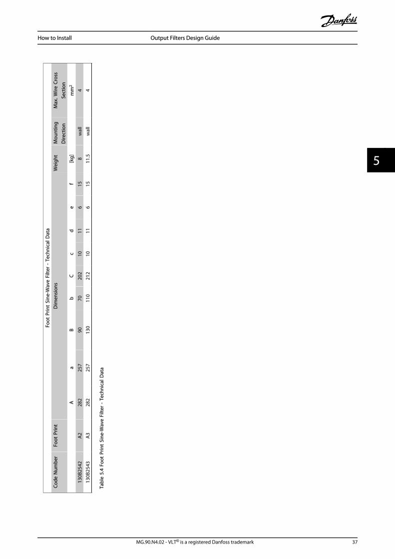
Foot
Prin
t Si
ne-W
ave
Filte
r -
Tech
nica
l Dat
aCo
de N
umbe
rFo
ot P
rint
Dim
ensi
ons
Wei
ght
Mou
ntin
gD
irect
ion
Max
. Wire
Cro
ssSe
ctio
n
A
aB
bC
cd
ef
[kg]
m
m2
130B
2542
A2
282
257
9070
202
1011
615
8w
all
413
0B25
43A
328
225
713
011
021
210
116
1511
.5w
all
4
Tabl
e 5.
4 Fo
ot P
rint
Sine
-Wav
e Fi
lter
- Te
chni
cal D
ata
How to Install Output Filters Design Guide
MG.90.N4.02 - VLT® is a registered Danfoss trademark 37
5 5
6 How to Programme the Frequency Converter
• The VLT® switching frequency must be set to thevalue specified for the individual filter. Pleaseconsult the VLT® Programming Guide for thecorresponding parameter values.
• With an output filter installed only a reducedAutomatic Motor Adaption (AMA) can be used.
NOTESine-wave filters can be used at switching frequencies higherthan the nominal switching frequency, but should never beused at switching frequencies with less than 20% lower thanthe nominal switching frequency.
NOTEdu/dt filters, unlike Sine-wave filters, can be used at lowerswitching frequency than the nominal switching frequency,but higher switching frequency will cause the overheating ofthe filter and should be avoided.
6.1.1 Parameter Settings for Operation with Sine-wave Filter
Parameter no. Name Suggested setting
14-00 Switching Pattern For Sine-wave filters choose SFAVM
14-01 Switching Frequency Sine-wave: Choose valuedu/dt: Choose max. value
14-55 Output Filter Choose Sine-wave filter fixed
14-56 Capacitance Output Filter Set the capacitance*
14-57 Inductance Output Filter Set the inductance*
*) For FLUX control principle only. Values can be found in the chapter Selection of output filter section Electrical Data - du/dt Filters and sectionElectrical Data - Sine-wave Filters
How to Programme the Freque... Output Filters Design Guide
38 MG.90.N4.02 - VLT® is a registered Danfoss trademark
66
Index
AAbbreviations 3
Accessory Bag 29
Acoustic Noise 12
Aggressive Environments 11
CCable Length 10
Capacitance 10
Capacitors 10
CE Conformity and Labelling 4
Common-mode Voltage 7
Conducted Noise 9
Cut Off Frequency 10
DDu/dt Ratio 5
EEarthing 29
Electromagnetic 5, 7
Electromagnetic Emissions 12
EMC 10
EMC performance 10
FFlash Over 11
GGeneral Purpose Motors 11
General Warning 3
HHarmonics 7
High Frequency 7
High-frequency Noise 7
High-voltage Warning 3
IIEC 6
IEC 600034-25 11
IEC60034-17 10
IEC-60034-17* 10
Impedance 5
Inductance 10
Inductors 10
Insulation 5
Insulation Stress 10
LLC-filter 12
MMagnetostriction 7
Maximum Cable Length 29
Motor Bearing Stress 10
Motor Cable 5
Mounting 28
NNEMA 6
NEMA-MG1 10
PPhase-to-phase 7
Pulse Reflections 12
Pulsewidth Modulated 7
RReflection Coefficient 5, 6
Regenerative Braking 11
Retrofit 11
RFI filter 10
Ringing Oscillation 8
SSafety Requirements For Mechanical Installation 28
Screened Cables 29
Sinusoidal 7, 8
Step Up Applications 13
TThe Low-voltage Directive (73/23/eec) 4
Tr 6
UUpeak 6
VVoltage Drop 10
Voltage Peaks 10
WWave Reflection 5
Index Output Filters Design Guide
MG.90.N4.02 - VLT® is a registered Danfoss trademark 39
www.danfoss.com/drives
*MG90N402*130R0457 MG90N402 Rev. 2010-05-03