outline of class 1 st part: how to make sketches entities relations dimensioning 2 nd part: how...
TRANSCRIPT
Introduction to
Part 3
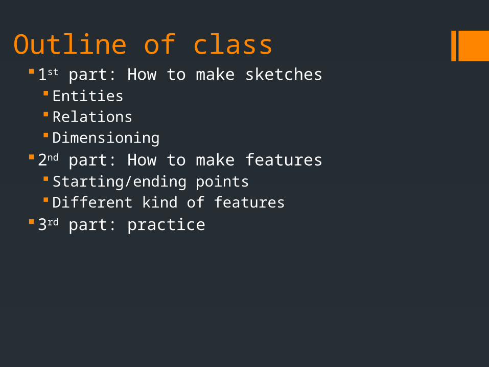
Outline of class1st part: How to make sketches
Entities Relations Dimensioning
2nd part: How to make features Starting/ending points Different kind of features
3rd part: practice
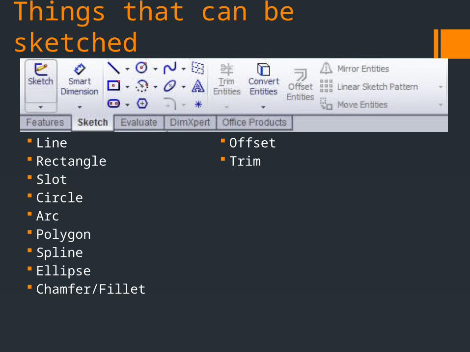
Things that can be sketched
Line Rectangle Slot Circle Arc Polygon Spline Ellipse Chamfer/Fillet
Offset Trim

Line
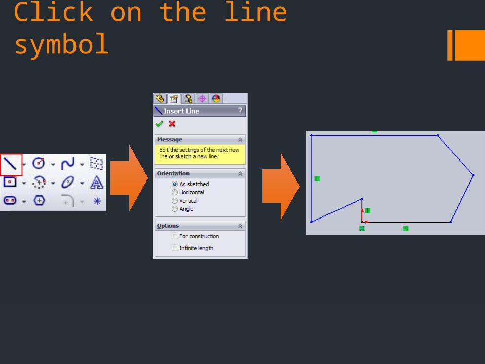
Click on the line symbol
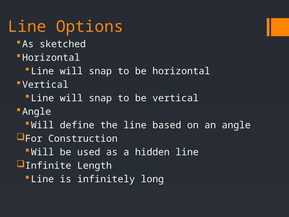
Line OptionsAs sketchedHorizontal
Line will snap to be horizontalVertical
Line will snap to be verticalAngle
Will define the line based on an angleFor Construction
Will be used as a hidden lineInfinite Length
Line is infinitely long
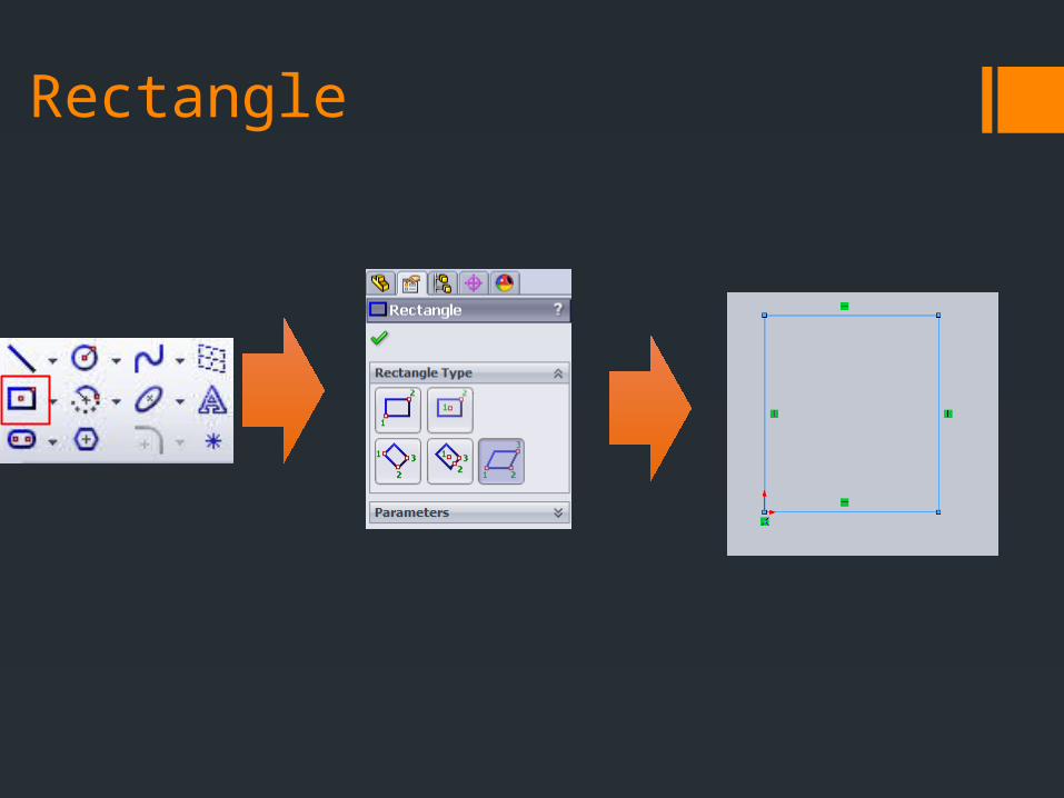
Rectangle

Rectangle Options
Corner Rectangle Assumes a horizontal rectangle
Center Rectangle Assumes horizontal
3 point corner rectangle Chose 3 points for the corners
3 point center rectangle Chose two points for a center axis
Parallelogram 3 points for a parallelogram
8
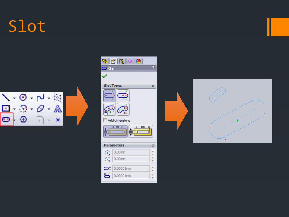
Slot
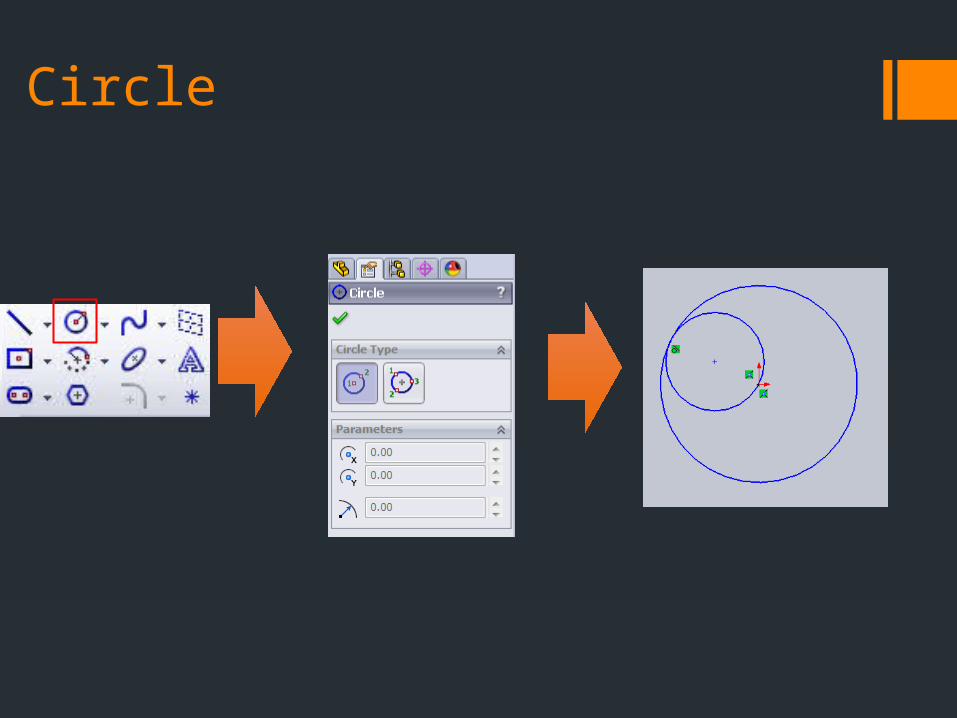
Circle
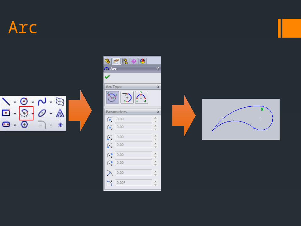
Arc
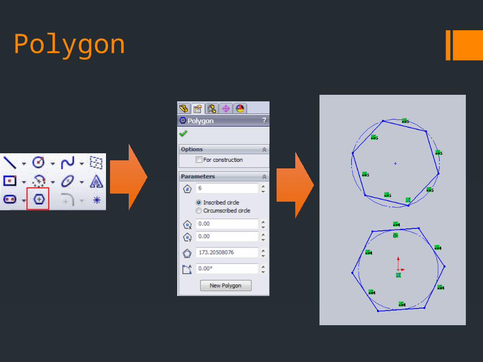
Polygon
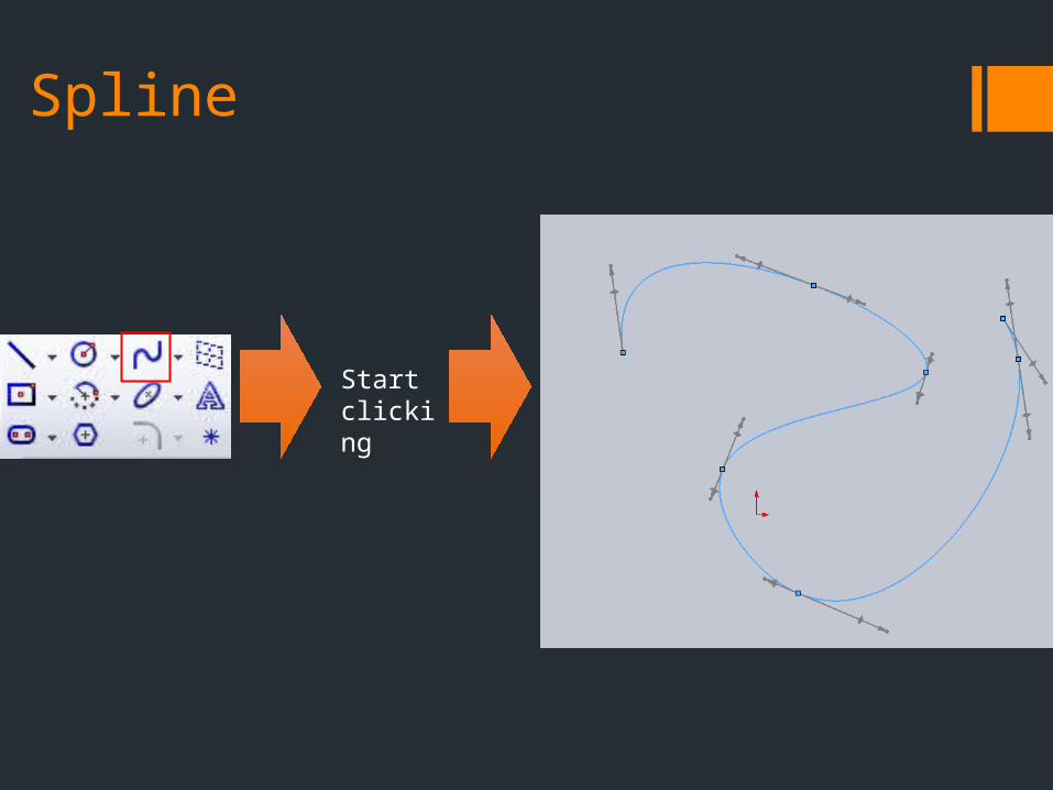
Spline
Start clicking
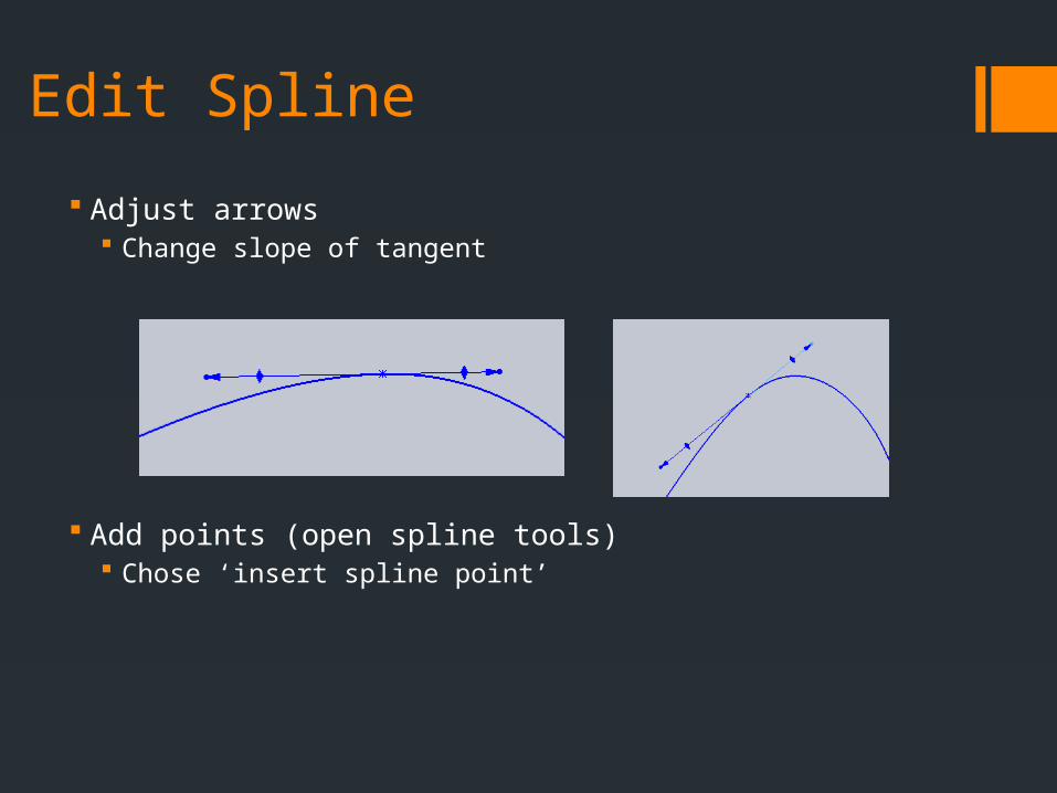
Edit Spline
Adjust arrows Change slope of tangent
Add points (open spline tools) Chose ‘insert spline point’
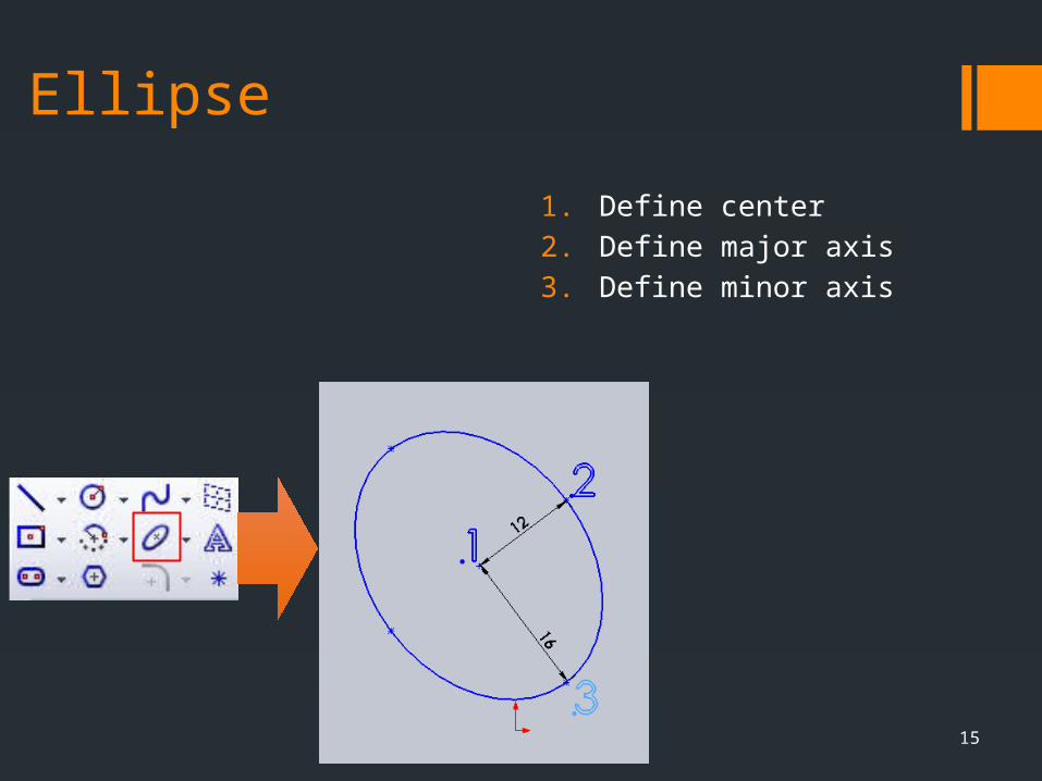
Ellipse
1. Define center
2. Define major axis
3. Define minor axis
15
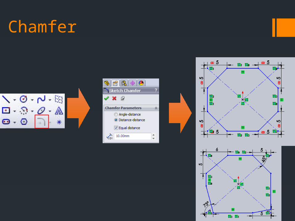
Chamfer
16
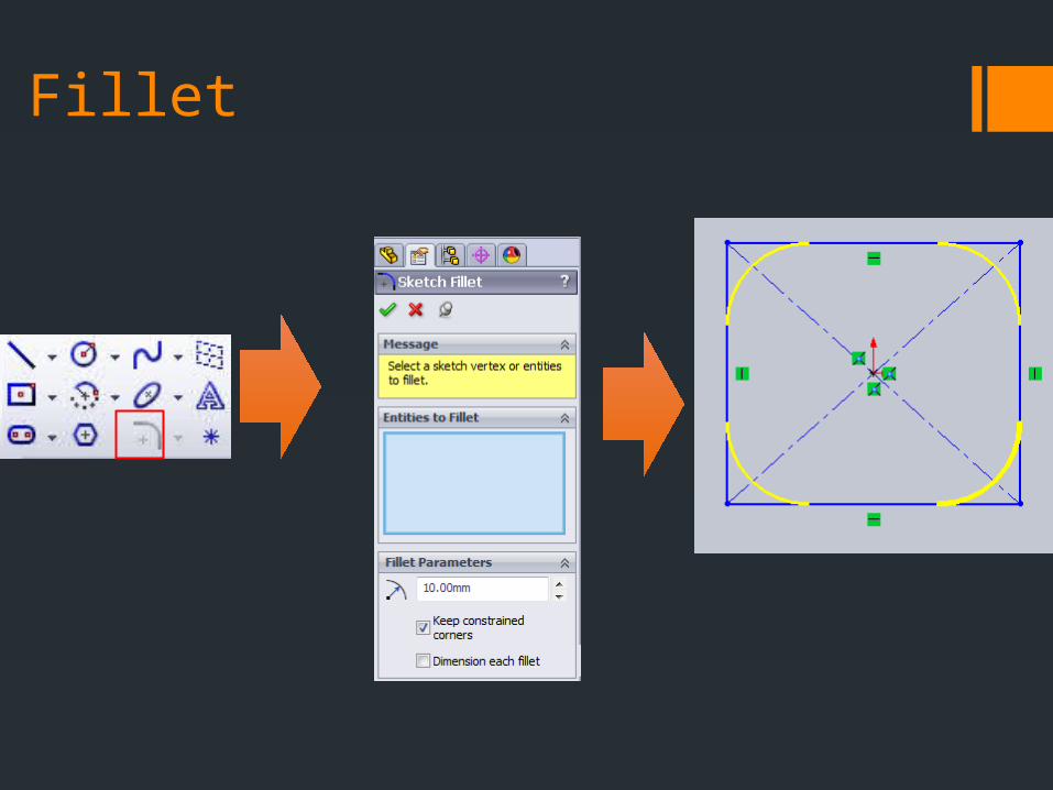
Fillet
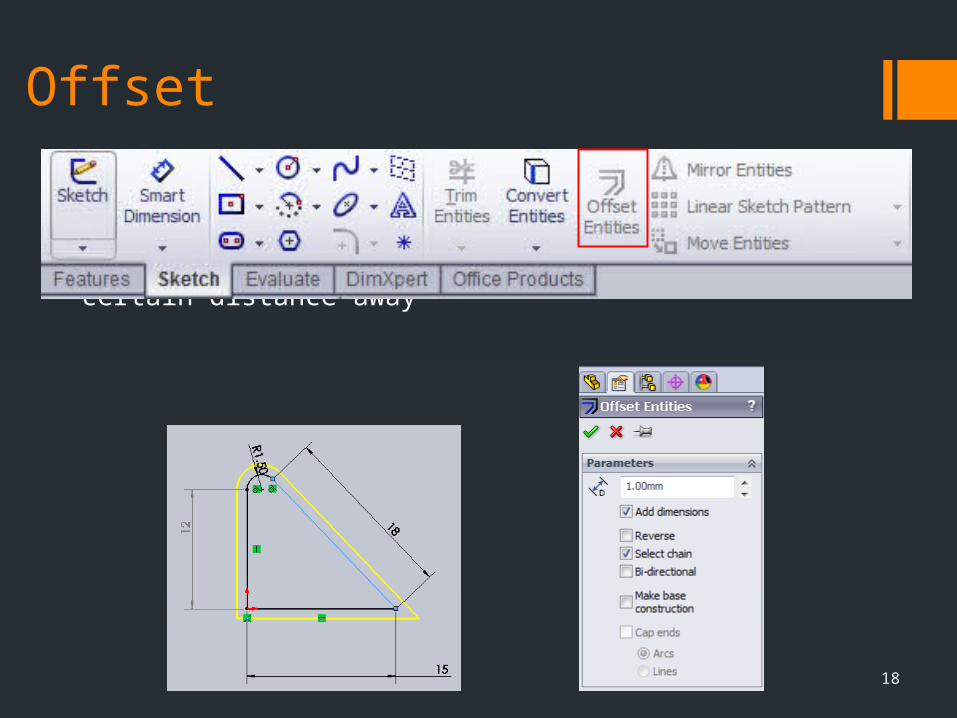
Offset
Creates a copy of selected sketch entities a certain distance away
18

Trim
Power Trim Trim all entities the mouse moves over
Corner Connect two lines
Trim away inside Cut lines passing through two entities
Trim away outside Cut lines extending past two entities
Trim to closest Cut the entity up to the next closest entity
19
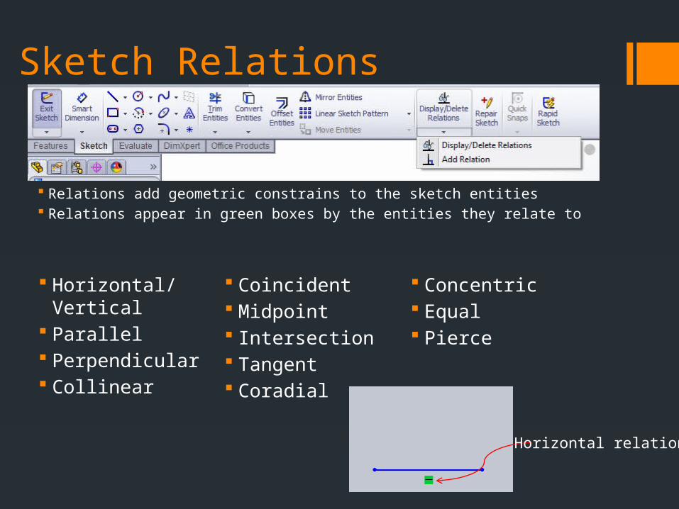
Sketch Relations
Relations add geometric constrains to the sketch entities Relations appear in green boxes by the entities they relate to
Horizontal relation
Horizontal/Vertical Parallel Perpendicular Collinear Coincident
Midpoint Intersection Tangent Coradial Concentric
Equal Pierce
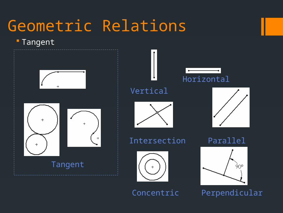
Geometric Relations Tangent
Tangent
Parallel
Horizontal
Vertical
Intersection
Concentric Perpendicular

Geometric Relations (These can be added automatically via hotpoints)
Horizontal Straight left to right
Vertical Straight up and down
Parallel Lines side by side and having
the same distance continuously between them
Perpendicular at an angle of 90° to a given
line Coincident
Coincident points will lie on a line/curve
Midpoint Point will at the center of a
line/curve Intersection
Point where two lines/curves cross
Tangent a line that touches a curve at a
point, but if extended does not cross it at that point.
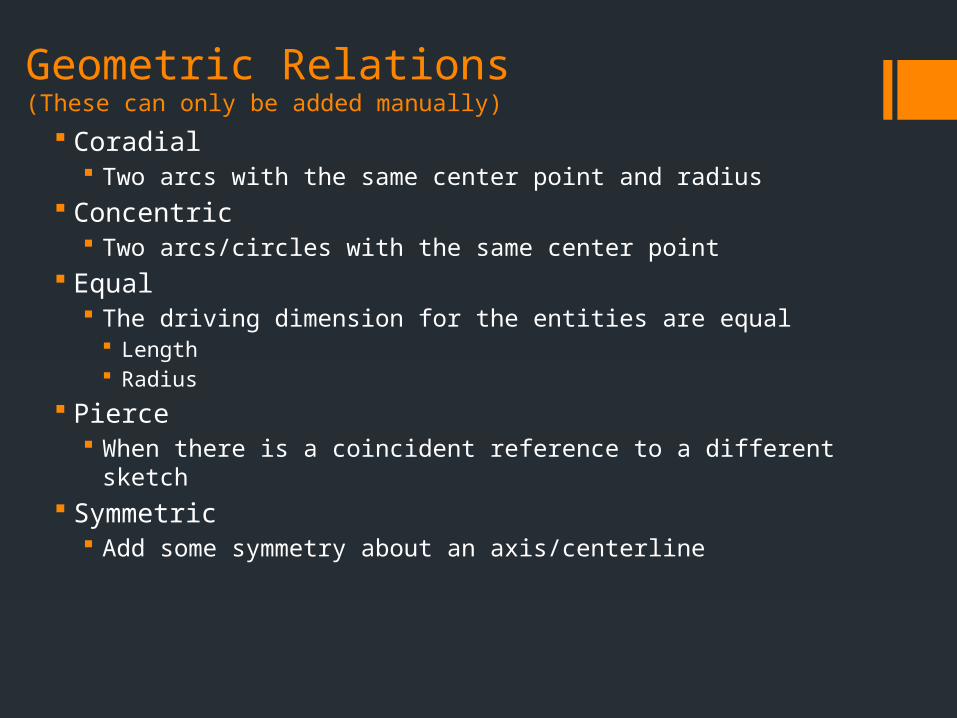
Geometric Relations (These can only be added manually)
Coradial Two arcs with the same center point and radius
Concentric Two arcs/circles with the same center point
Equal The driving dimension for the entities are equal
Length Radius
Pierce When there is a coincident reference to a different sketch
Symmetric Add some symmetry about an axis/centerline

How to constrain
Click ‘Add Relation’ Select entities Make the relation
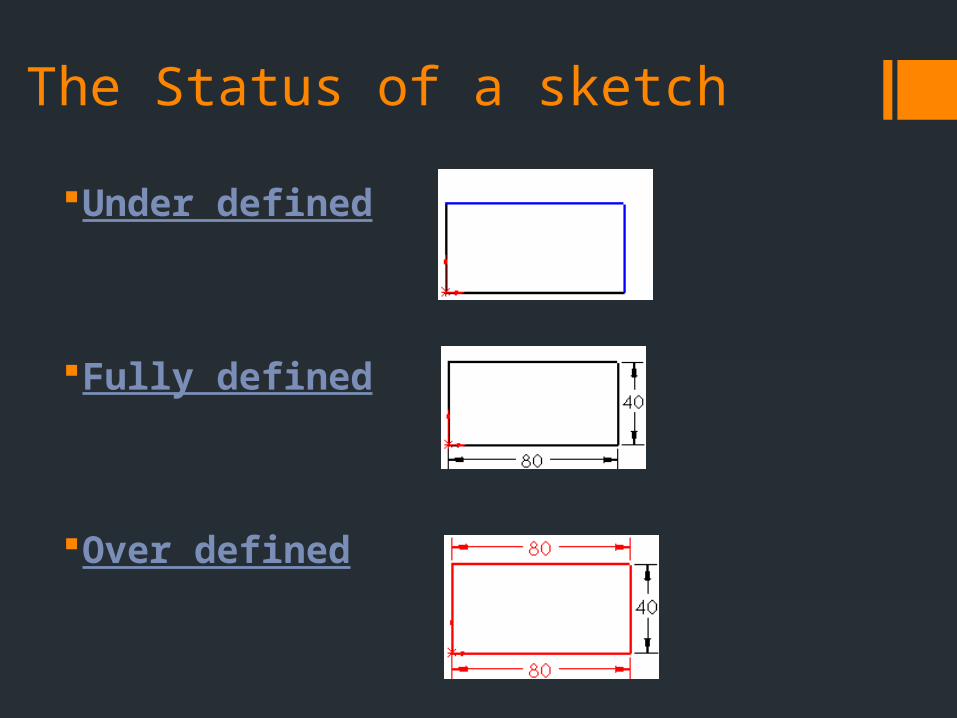
The Status of a sketch
Under defined
Fully defined
Over defined
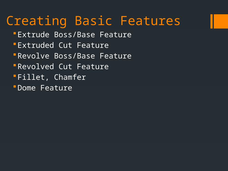
Creating Basic FeaturesExtrude Boss/Base FeatureExtruded Cut FeatureRevolve Boss/Base FeatureRevolved Cut FeatureFillet, ChamferDome Feature
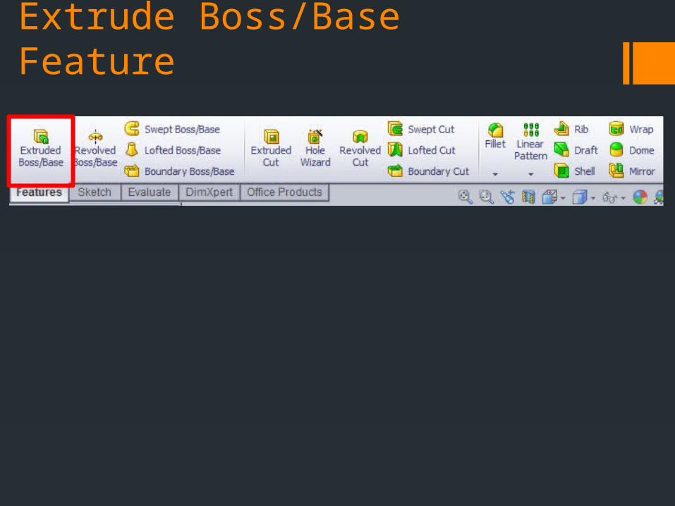
Extrude Boss/Base Feature

Where to start the extrusion
Where to end the extrusion
Can extrude in a second direction
Can extrude from a thin feature or a contour
Add a draft to the part
Can choose the angle of extrusion
FromSketch Plane
The plane of the sketch
Surface/Face/PlaneCan choose any face
VertexCan choose a point for reference to start
OffsetCan enter a quantity to offset from surface
Direction 1/Direction 2Blind
Extrudes a specified distance
Through All Goes through all bodies
Up To Next Extrudes to the nearest feature
Up to Vertex Up to a specified point
Up to Surface Can choose a surface to extrude to
Offset from Surface Can set a distance from a selected surface
Up to Body Similar to surface, but can choose a whole object (body)
Midplane Extrude in two directions with the current plane set as center
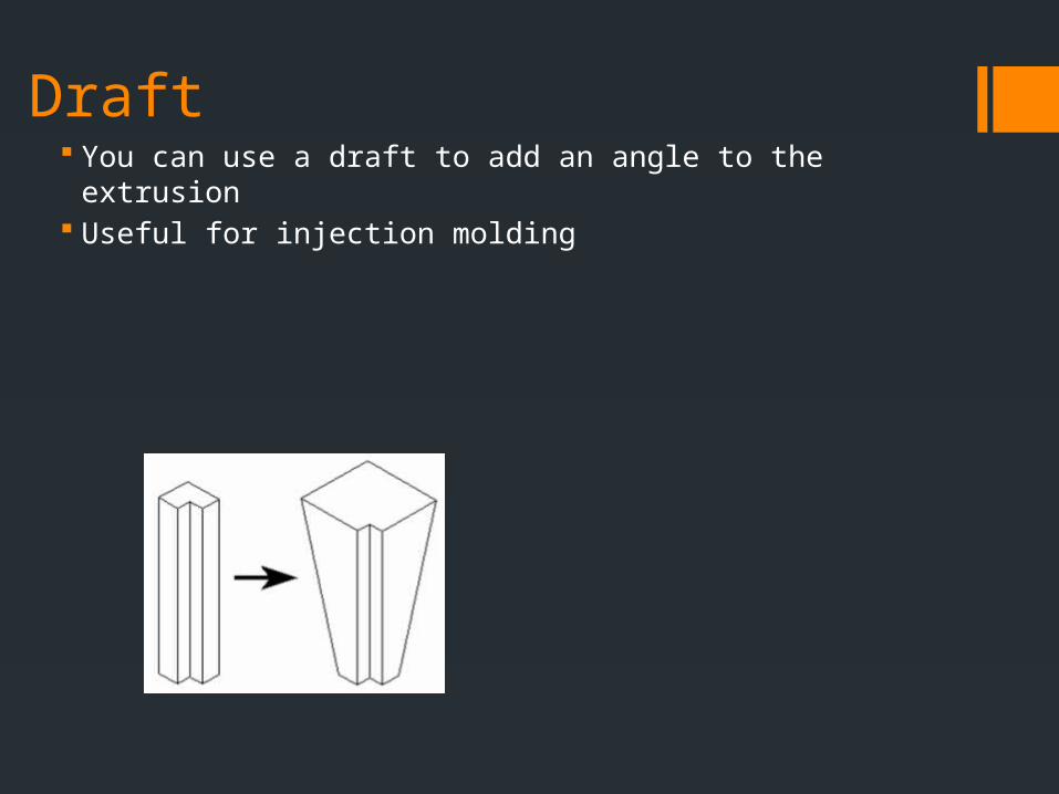
Draft You can use a draft to add an angle to the extrusion Useful for injection molding
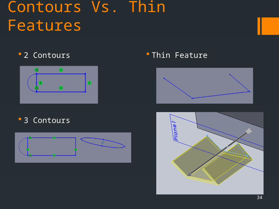
Contours Vs. Thin Features
2 Contours
3 Contours
Thin Feature
34
Thin Feature One direction Midplane Two-direction
Sets the thickness of the extruded feature
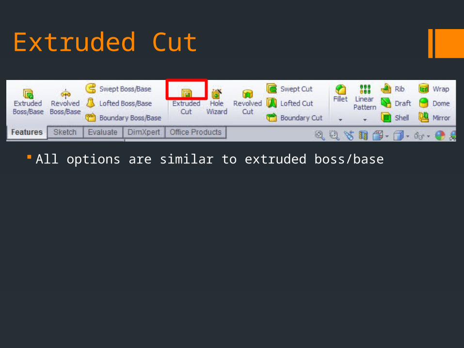
Extruded Cut
All options are similar to extruded boss/base
Revolve Boss/Base Feature

Axis of revolution
Where to end the extrusion
Can revolve from a thin feature or a contour

Revolved Cut Feature
Fillet

Fillet Types Constant Radius
Entire fillet has a constant radius Variable Radius
Radius varies Face fillet Full round fillet
Rounds off bosses or ribs

Chamfer

Dome
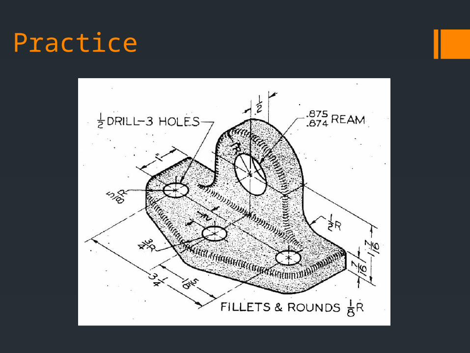
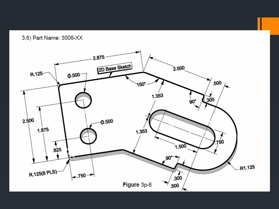
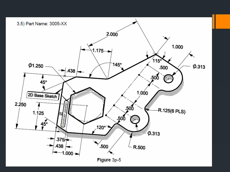
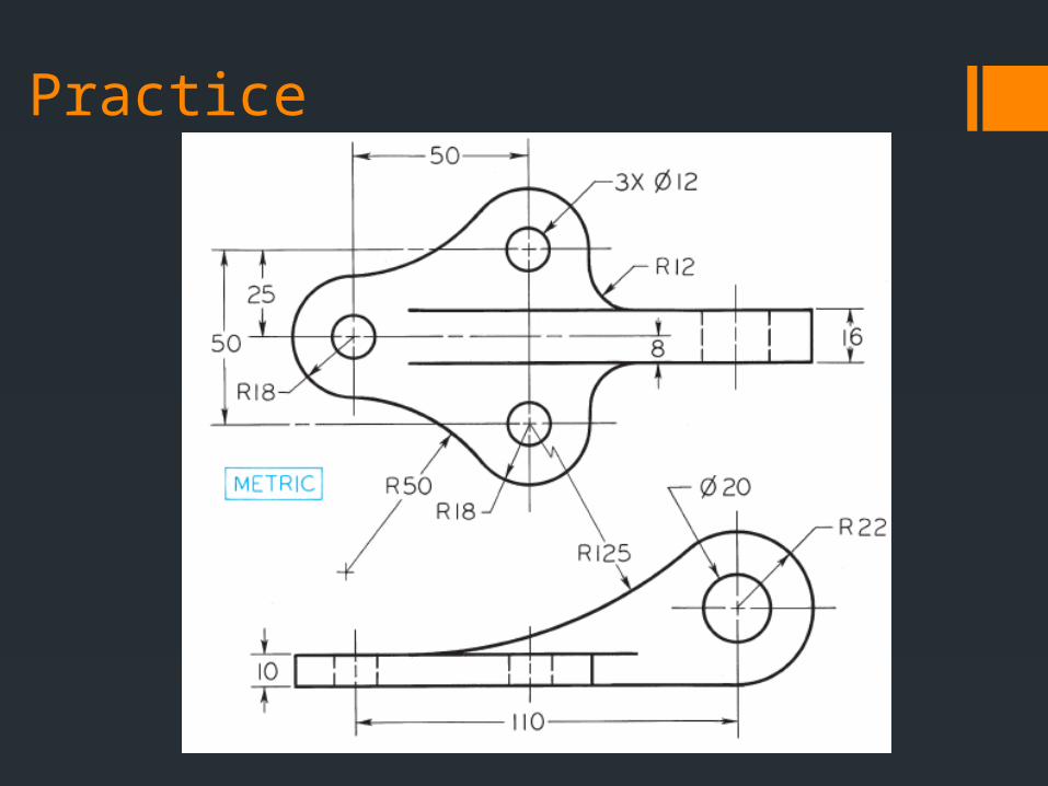
Practice
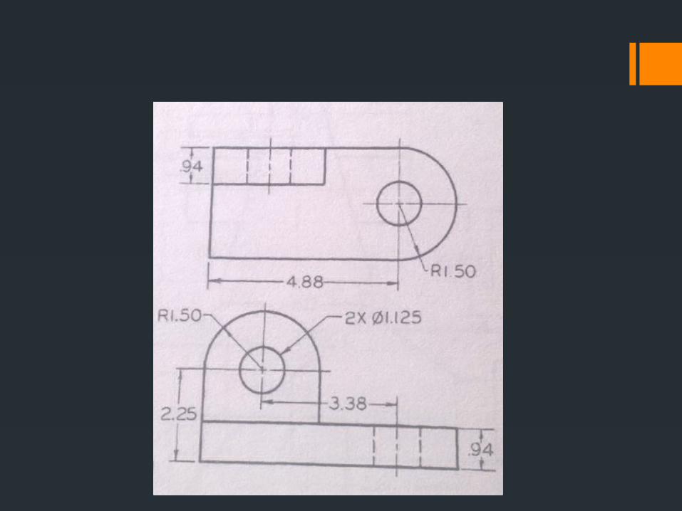
Practice

Additional Stuff

Sweeping Normal extrusion restricts your extrude to a linear path. Sweeping is when you extrude along a path

Sweeping In order to sweep, you need two things Sketch profile Path sketch
The path must start in/on the sketch profile.

Lofting Lofting is when you have multiple cross sections, and the part
extrapolates the extrude from cross section to cross section

Lofting Need to make multiple sketches of multiple cross sections
Additional Stuff Mirror Patterns Shell