outer hcal sector steel design and procurement review · • report of the final design review and...
TRANSCRIPT

Outer HCal Sector Steel Design and Procurement Review
sPHENIX Responses to Committee Recommendations, and Follow-Up Questions
sPHENIX Engineering Staff
Review Date: January 31, 2018
Follow Up Review: April 5, 2018

12/14/17sPHENIX Integration & Installation Status
Report2
Responses and supporting documentation prepared by: Don Lynch, Jim Mills, Steve Bellavia, Anatoli Gordeev, Dan Cacace, Rich Ruggiero, Chris Pontieri, Spencer Laddy-Locks and Kin Yip
The Review Committee: Mike Anerella (chair), Charley Folz, Maia Chamizo-Llatas, Frank De Paola, Ed Lessard, Joe Tuozzolo and Bill Wahl.
The committee made 14 recommendations/action items to be addressed prior to execution of the option to purchase the 32 production sectors from the existing sPHENIX contract with Strecks, Inc., and an additional 20 recommendations were made based on committee review of the sPHENIX Outer Hadronic Calorimeter (HCal) sector design, QA and procurement documentation.
sPHENIX engineers accept the findings of the committee that the additional analyses and clarifications requested are appropriate and necessary for the committee to properly evaluate the barrel flux return steel prior to endorsing the execution of the contract option with the Vendor, Streck’s. sPHENIX engineers believe that we have adequately addressed each and every recommendation and action item with full and comprehensive analyses as reported in this document and the supporting documents to this report.

12/14/17sPHENIX Integration & Installation Status
Report3
Support Documents
The following documents are supplied as support materials for this report:
• Report of the Final Design Review and Procurement Readiness Review of the Barrel Flux Return Steel of sPHENIX• sP.EAR-2018-006: Design and Structural Analyses of the sPHENIX mechanical interface/support for the sPHENIX
Superconducting Solenoid Magnet and the Outer HCal Sector Steel Assembly • sP-SE.QAM.002: sPHENIX Documentation Control• sP-SE.QAM.003: sPHENIX Configuration Management• sP-SOW.001: Statement of Work (SOW) Outer HCal Sector Structural Assemblies • sP.EAR-2018-003: Structural Design Analyses Report: sPHENIX Outer HCal Sector: Handling• sP.EAR-2018-002: Structural Design Analyses Report: sPHENIX Outer HCal Sector: Shipping• sP.EAR-2018-004: Structural Design Analyses Report: sPHENIX Outer HCal Sector: Assembly• sP.EAR-2018-005: Structural Design Analyses Report: sPHENIX Outer HCal Sector: Operational Design Case• sP-SE.QAM.007: sPHENIX Quality Assurance Plan• Outer HCal Factory Workplan (draft)• Design Questionaire: Outer HCal Factory• Design Questionaire: Entire sPHENIX Detector at Bldg 1008• sPHENIX Outer HCal drawing package. (15 Drawings, see SOW for list)• sP-DOC-2018-001: Outer HCal Thermal Expansion Calculations• Effects of Outer HCal structural elastic deformation due to full operational loading.• Critical Lift Evaluation Form (CLEF) for Outer HCal Sector lifting fixture.• sP.EAR-2018-007: Outer HCal Sector Lifting Fixture Design Analyses
These documents are posted on the Indico web page: https://indico.bnl.gov/event/4501/

12/14/17sPHENIX Integration & Installation Status
Report4
Additional Documents not posted, but available for review, on request:
• sPHENIX Risk Registry• sPHENIX Recommendations Tracking System (RTS)• Streck’s Quality Control Manual (Streck’s commercial proprietary)• BNL Supplier Survey for Streck’s (Streck’s commercial proprietary)
Additional Analyses Requested for April 5, 2018 follow up review:
• Tolerance Stack up Calculations• Buckling analyses of Splice plates attached to End Plates with 3/4 “ bolts• Stress analyses with 2 pins remove from each splice plate• Bolt Stress in Chimney sector plate attachment bolts
These are addressed in this presentation

12/14/17sPHENIX Integration & Installation Status
Report5
Charge for today’s meeting (from Mike Anerella:
The subject meeting will be held to formalize acceptance of the sPHENIX Project responses to action items originating from the previous review, specifically, the fourteen “pre-award recommendations listed in the January 31, 2018 review report. These are listed below, along with some comments which have resulted from an intermediate meeting and other discussions among sPHENIX Project members and the committee.
1. Provide adequate description of interfaces between solenoid coil / cryostat and barrelflux return steel. Addressed in Report sP.EAR-2018-006 posted on Indico site: https://indico.bnl.gov/event/4501/
On this subject, the system of hydraulic cylinders beneath the cryostat were agreed to besuitable interfaces. However, it was not demonstrated that sPHENIX had fullyaccommodated lessons learned from the high power test in Building 912, where similarcomponents were able to support, but not successfully adjust, cryostat position withoutrisking damage to the cryostat, which leaves sPHENIX still needing adjustmentprocedure / equipment development as an open issue prior to installation.
2. Provide released configuration control documents and coordinate with C-AD. Released documents posted on Indico site: https://indico.bnl.gov/event/4501/
Subsequent to the January 31, 2018 reviews, sPHENIX engineering met with Lee Hammonds, Roy Lebel and Chuck Gortakowski. Chuck was assigned to replace Jack Eng and provide QA support for sPHENIX. Chuck was provided with copies of sPHENIX draft QA documentation. Chuck offered comments and advice on the sPHENIX Documentation Control and Configuration Management Procedures and these have been revised and are included with the support documents for this report.

12/14/17sPHENIX Integration & Installation Status
Report6
3. Provide a released Statement of Work for the procurement. Released SOW posted on Indico site: https://indico.bnl.gov/event/4501/
A detailed review of the new draft Statement of Work is anticipated at this follow-upmeeting.
sPHENIX Statement of Work (SOW) for the sPHENIX Outer HCal Steel sector, which was a requirement for the prototype procurement, was provided at the January 31, 2018 review. This has been revised to reflect the modified requirements appropriate for the production procurement option. The update has been reviewed by the Vendor, BNL procurement (Emily Mastronardi) and sPHENIX QA (Chuck Gortakowski). This document is provided with the support documents for this report.
The following slides provide a full description of the SOW.

SOW for Outer HCalReleased and approved
4/4/2018

12/14/17sPHENIX Integration & Installation Status
Report8
SOW Revision record

12/14/17sPHENIX Integration & Installation Status
Report9
TofC
12/14/17sPHENIX Integration & Installation Status
Report10
General Info
12/14/17sPHENIX Integration & Installation Status
Report11
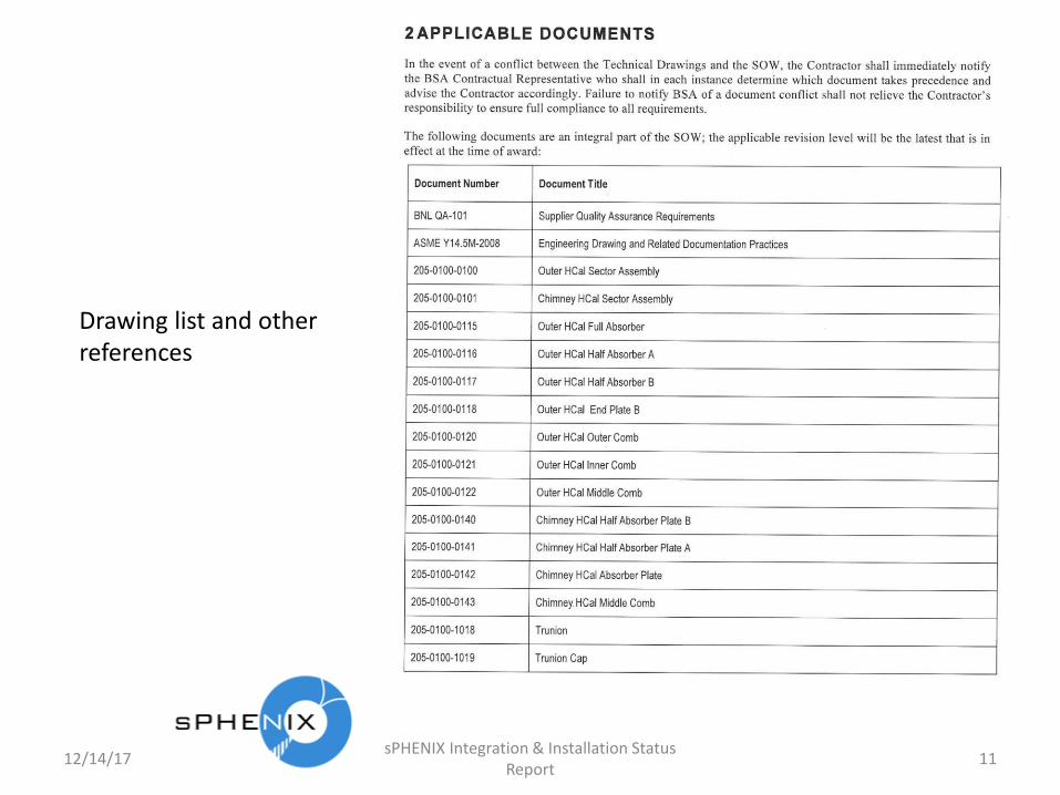
Drawing list and otherreferences

12/14/17sPHENIX Integration & Installation Status
Report12
Requires 2 different sector types: Sector and Chimney HCal Assemblies
1st production unit inspection requirement
Contractor supplies all materials and tools
sPHENIX responsible for design, Contractor responsible to meet SOW and drawing dimensions, and to make tooling/fixtures as needed to inspect and verify.

12/14/17sPHENIX Integration & Installation Status
Report13
Contractor must meet all requirements and use 1020 steel
Post contract award coordination
Detailed program plane including milestones for all significant efforts during the conmtract

12/14/17sPHENIX Integration & Installation Status
Report14
MITP identify how manufacturing will be tracked and monitored. Travelers or equivalent.
Monthly Reports
End Item documentation package

12/14/17sPHENIX Integration & Installation Status
Report15
CM system required. Records required
Acceptable formats for drawing exchange
Sectors must have serial #’s
10 year warranty
Contractor responsible for protecting sectors under all conditions after fabrication, particularly for shipping

12/14/17sPHENIX Integration & Installation Status
Report16
Quality management system equivalent to ISO-9001.
BNL-QA-101 requirements. See next 6 slides
Inspection, report temperature control, inspection of 1st
production unit

12/14/17sPHENIX Integration & Installation Status
Report17
3.1.2 A quality system that meets the requirements of the ISO 9001 standard: “Quality Management Systems –Requirements” (latest revision as of the date of issuing the procurement documentation).
BNL-QA-101 Applicable Paragraphs
3.2 Assessment by Buyer The Supplier’s quality system is subject to assessments by the Buyer’s Representative(s) for conformance with the requirements of the PO. Supplier or Distributor shall allow BSA representatives, BSA customers, and regulatory agencies right of entry into the Supplier’s facilities to determine and verify product, processes, records, personnel, material, procedures, and systems.
3.3 Change ApprovalNo change(s) shall be made to any Buyer requirements, (e.g. part number, model number, etc.) without the prior written approval of the Buyer.
3.4 Responsibility for SubcontractorsIt is the responsibility of the Supplier to impose applicable quality assurance requirements upon their subcontractors. Additionally, the Buyer reserves the right to disapprove, in writing, any subcontractor.
3.5 Responsibility for ConformanceThe Supplier is responsible to provide items that conform to the requirements of the PO regardless of any assessments, surveillances, inspections and/or tests by the Buyer or its representatives at either the Supplier’ or Buyer’s facility. The Buyer reserves the right to request failure analysis and corrective action for non-conforming articles or items submitted or supplied to the Buyer. The Supplier is responsible for notifying the Buyer of any recalls or alerts associated with this PO.

12/14/17sPHENIX Integration & Installation Status
Report18
3.6 Protection of Material and EquipmentThe Supplier shall employ procedures that assure adequate protection of material and equipment during shipment and while in storage. Such protection shall include special environmental packaging, as necessary. All items shipped (originally packaged or repackaged) to BNL or other locations cited in the PO or contract, shall comply with the requirements for preservation, packaging and marking as stated in the latest revision of ASTM Standard D 3951 Standard Practice for Commercial Packaging.3.7 Measuring and Test Equipment (M&TE) CalibrationThe Supplier shall calibrate any M&TE used in the fulfillment of the PO requirements against certified standards that are traceable to the National Institute of Standards and Technology (NIST), or some other recognized national or international standard, or physical constant. The Supplier shall notify the Buyer of any condition found during the calibration, servicing or repair of measuring and test equipment that can affect the end item requirements.3.8 Suspect Counterfeit PartsThe Supplier shall verify the procurement source and associated certifying paperwork.Appropriate incoming inspection test methods shall be used to detect potential counterfeit parts and materials.The Supplier shall flow this requirement down to all sub-tier suppliers to prevent the inadvertent use of counterfeit parts and materials. Distributors shall not modify, rework or repair material shipped on this order.* For more information refer to the following Department of Energy website: http://www.hss.energy.gov/sesa/corporatesafety/sci/
3.9 Electrostatic Discharge Control Items that are susceptible/sensitive to electrostatic discharge (ESDS) shall be handled and packaged to protect them from damage. Items and/or packages shall be labeled to indicate the susceptibility to electrostatic discharge.

12/14/17sPHENIX Integration & Installation Status
Report19
3.12 Marking of Outer Package and Hoisting & Rigging ServicesEach shipping container (transport package) with a gross weight equal to or greater than 400 pounds (180 kilograms) must be marked with the center of gravity location and gross weight on at least one side, or end panel in addition to meeting the requirements of the latest revision of ASTM Standard D 3951, Standard Practice for Commercial Packaging. This applies to any item shipped (originally packaged or repackaged) to BNL or other locations cited in the PO or contract.
Due to weight, size, and/or volume parameters of the end item(s) requiring special material handling/rigging by BSA personnel; advanced notice of delivery of 3 business days minimum shall be provided by the supplier or shipper to BSA’s Receiving department both by telephone at: 631-344-2300 or 4336 AND via email at: [email protected] . The supplier or shipper must obtain documented acknowledgement from BSA that delivery notification was received. Failure to contact BSA will result in delays during delivery and demurrage will be at the Supplier’s/shipper’s expense.
(Sections 3.13 to 3.20 do not apply to this procurement)
4.2Configuration Control SystemThe Supplier shall establish and maintain a system to assure that all end items (including spares) are of the proper configuration, and that all approved configuration changes are incorporated at the specified effectivity points. Records shall be maintained to verify the configuration of each item.
4.4 Manufacturing/Inspection/Test PlanSixty (60) calendar days prior to performance of work, the Supplier shall submit for the Buyer’s approval a Manufacturing/Inspection/ Test Plan for the item(s) to be produced. Once approved, changes/ revisions must be approved by the Buyer prior to implementation. The Plan shall satisfy one or more of the following as selected:
4.4.3 The Plan may be a single document, or may make use of existing “travelers,” or other suitable planning and control documents.

12/14/17sPHENIX Integration & Installation Status
Report20
4.5 “Witness” PointsThe Buyer reserves the right to designate selected manufacturing, inspection, and/or test operations as “witness” points. The Supplier shall provide the Buyer with five (5) working days notice in advance of reaching such witness points during the manufacturing and test cycle of each item.
4.6 Test and Inspection ProceduresTest and inspection procedures required to demonstrate satisfactory completion of requirements shall be prepared by the Supplier and submitted to the Buyer for approval sixty (60) calendar days prior to use of such procedures. Once approved, changes/revisions must be approved in writing by the Buyer prior to implementation.
4.7 Special ProcessesProcesses (e.g., welding, brazing, bonding, plating, chemical machining, chemical coating, chemical cleaning, precision cleaning, heat treating, or waste processing) that either cannot be verified non-destructively or require a unique (special) non-destructive test / inspection (e.g., radiographic inspection, ultrasonic testing, pressure leak testing) shall be performed in accordance with detailed written procedures. These procedures shall specifically describe the exact manner in which the processes are to be performed. Additionally, the following requirements apply as selected:
4.7.1 Copies of special process procedures shall be made available on request for review by the Buyer’s representative.
4.10 End-Item Documentation PackageThe Supplier shall provide a documentation package for each shipment of the item(s) supplied, which consists of objective evidence of compliance with PO requirements. This documentation package shall be complete, legible, indexed, and traceable to the item supplied. Additionally, the following requirements apply as selected:
4.10.3 Copies of nonconformance reports dispositioned as “rework / repair” or “use-as-is”, and all BSA approved deviation/waivers.

12/14/17sPHENIX Integration & Installation Status
Report21
4.10.4 Copies of material test certificates for specified materials, showing physical and chemical properties.
4.16 Certificate of Conformance (C of C)With each shipment, per the procurement documentation, the Supplier shall submit a Certificate of Conformance (C of C). In case of drop shipment, a copy of the certificate shall be submitted to the Buyer at the time of shipment. The certificate shall include the title of and be signed by an authorized representative of the company, and shall constitute a representation by the Supplier that:
A. Materials used are those which have been specifiedby the Buyer, and that the items delivered were producedfrom materials for which the Supplier has on file, reports of chemical or physical analysis, or any other equivalent evidence of conformance of such items to applicable specifications;
B. Processes used in the fabrication of items deliveredwere in compliance with applicable specifications included as part of the PO/contract, or Buyer-approved procedures or specifications;
4.18 First Article AcceptanceBuyer acceptance of first article(s) is required prior to the production run. The first article(s) shall be identified as such, including the PO number/contract, part number, and part name. The Supplier is required to:
4.18.1 Submit the first article(s) to the Buyer’s representative for test/inspection to be conducted at the Supplier’s facility by the Buyer’s representative.

12/14/17sPHENIX Integration & Installation Status
Report22
4.18.3 Submit the first article(s) to the Buyer togetherwith documents showing data representing results of the Supplier’s first article(s) test/inspection, including the actual dimension or value for each specified characteristic.4.18.4 After Buyer acceptance of first article(s), all of theremaining units required by the PO/contract shall be produced by the Supplier and the Supplier’s suppliers using the same design, materials, processes, methods and tooling that were used to manufacture the approved first article(s). Any changes must have prior written approval from the Buyer.
4.19 Notification of Change to Design, Methods, or ProcessesThe Supplier shall immediately notify the Buyer of any significant changes (those that may affect form, fit, function, reliability, safety, or interchangeability) in product design, fabrication methods, materials, or processing from those used by the Supplier at time of Supplier’s quotation or offer to the Buyer, which resulted in the PO.
4.21 Serial NumbersThe Supplier shall assign/mark a separate and distinct serial number to each end-item in accordance with the procurement documentation. A record of the serial number, for each part number, shall be maintained by the Supplier.
4.23 Material TraceabilityMaterials used must be identified by material type, applicable specification and revision number, and be traceable to their lot and/or heat number(s). Traceability records shall be available for review by the Buyer’s representative.
4.39 RecordsThe Supplier shall retain objective evidence, including records, of the inspections and tests performed in the course of manufacturing, testing, inspecting, preserving, packaging, and preparation for shipment of procured items. These records shall be made available to the Buyer’s representative for review upon request. These records shall be maintained for a minimum of three (3) years, unless otherwise specified in the procurement documentation, after the completion of the PO/contract.

12/14/17sPHENIX Integration & Installation Status
Report23
MRB limits
QA Flow Down
12/14/17sPHENIX Integration & Installation Status
Report24
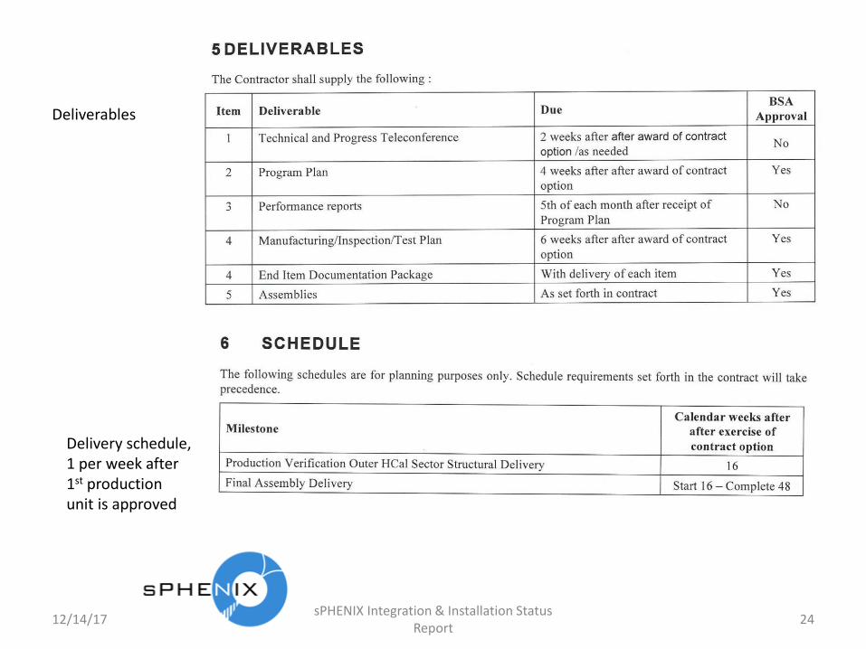
Deliverables
Delivery schedule, 1 per week after 1st production unit is approved
12/14/17sPHENIX Integration & Installation Status
Report25
Boiler plate, probably not applicable to this procurement

12/14/17sPHENIX Integration & Installation Status
Report26
4. Incorporate in the contract an acceptable end plates baseline design and set a point foranother review before production of the end plates.
Changes since the previous review have been to the splice plate design and incorporation of locating “pucks” between splice plates in an effort to simplify the assembly process of locating and installing sectors. This change is seen as positive. However there remain issues with over constraints that may result in two of the support pins between splice blocks and end plates to remain unloaded. Near the horizontal axis the cylindrical ring made up of splice plates and pucks approximate a continuous vertical structure, independently supporting sectors without accumulating loads from successive sectors on end plates. Near the vertical axis, however, the orientation of the sectors and the steep angles of the puck to splice plate mating surfaces results in the pucks not offering suitable support to the weight of the sectors, and so (ignoring bolt frictional effects) there may be relative slippage of adjacent sectors until at least one of the two unloaded support pins makes contact with both splice plate and end plate. This condition, if correctly understood, and any other condition arising as a result of the loading of only two of the four support pins in each end plate, should be examined for suitability with regard to mechanical stresses in the end plates and deflections in the complete assembly.
5. Finalize structural analysis including assembly, seismic, magnetic and shippinganalyses. Include updates, if any, relating to (5) above.
sPHENIX engineering has continued the structural analyses initially presented at the January 31, 2018 review. It should be noted that there has been no change to the end plate design and this recommendation is interpreted that the review committee is actually referring to the splice plates (“dog bones”), which connect the sectors via pins into the end plates. sPHENIX engineering has performed the required structural analyses to demonstrate that the sectors in their entirety, the pins and the splice plates are structurally sound, maintaining a factor of safety greater than 2.0 under all conditions of shipping, handling, assembly and operation (including magnetic and seismic loading). Separate reports for each of these conditions have been prepared and are provided with the support documents for this report (see supporting documents sP.EAR-2018-002, sP.EAR-2018-003, sP.EAR-2018-004, sP.EAR-2018-005). Todays meeting is the follow up review.

Outer HCal Sector Steel Review
Small Pins
sPHENIX Engineering Staff
8/13/2019 27

Set up
• Pins that are pre attached to the sector are transition fit.
• Pucks are transition fit.
• Pins that are attached to the next sector during assembly are clearance fit by 0.011”.
• All pin contacts are rough (separation, no sliding).
• End plates and splice plates have no contact.
• Bottom of cradle is fixed.
8/13/2019 28

Stress
8/13/2019 29

Deflection
8/13/2019 30

Shear stress in chimney bolts
• Simple Hand Calc:
• 𝑆 =𝐹
𝐴𝐶𝑆=
3000
4∗𝜋∗0.212=
5.4𝑘𝑠𝑖
8/13/2019 31

12/14/17sPHENIX Integration & Installation Status
Report32
Splice Plate Buckling Study
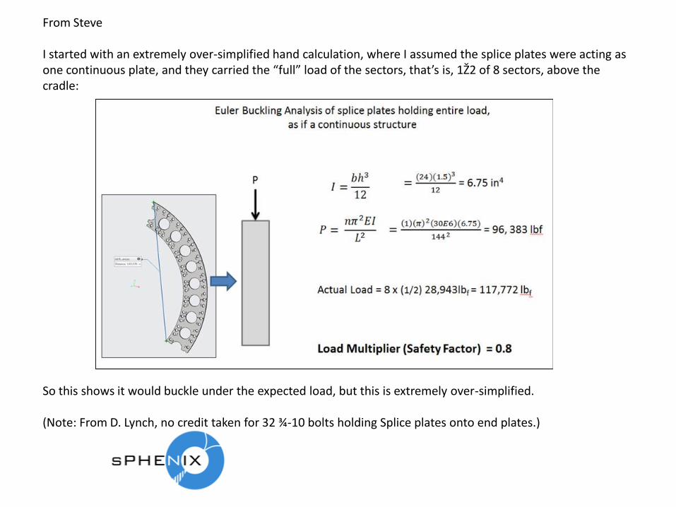
From Steve
I started with an extremely over-simplified hand calculation, where I assumed the splice plates were acting as one continuous plate, and they carried the “full” load of the sectors, that’s is, 1Ž2 of 8 sectors, above the cradle:
So this shows it would buckle under the expected load, but this is extremely over-simplified.
(Note: From D. Lynch, no credit taken for 32 ¾-10 bolts holding Splice plates onto end plates.)
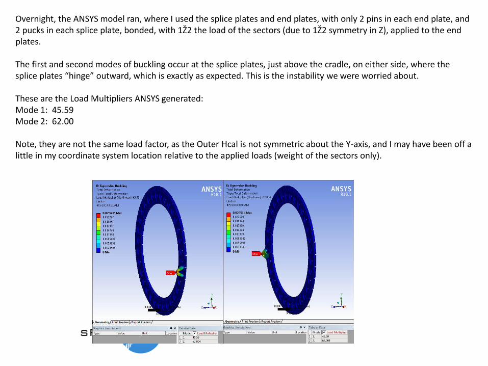
Overnight, the ANSYS model ran, where I used the splice plates and end plates, with only 2 pins in each end plate, and 2 pucks in each splice plate, bonded, with 1Ž2 the load of the sectors (due to 1Ž2 symmetry in Z), applied to the end plates.
The first and second modes of buckling occur at the splice plates, just above the cradle, on either side, where the splice plates “hinge” outward, which is exactly as expected. This is the instability we were worried about.
These are the Load Multipliers ANSYS generated:Mode 1: 45.59Mode 2: 62.00
Note, they are not the same load factor, as the Outer Hcal is not symmetric about the Y-axis, and I may have been off a little in my coordinate system location relative to the applied loads (weight of the sectors only).
I was a little surprised, as I expected the same, or worse, than the hand calculation, as the splice plates are not a continuous structure, and only connected by the pins.
But I think what is happening is that the end plates (the sectors) and pins are providing another level of “stability”, because the contacts are bonded (you can only use bonded or no-separation in an Euler-buckling analysis).And this may be somewhat realistic, as they are heavily loaded, so the friction force will be very large and likely prevent any sliding (in the 2-pin/2-puck case).Another thing to note is that since this is a symmetric-about-Z model, so there is no displacement allowed in Z. So that if the structure wanted to “parallelogram”, this model would not allow it.
This was done very quickly, so it may take much more time to truly understand the statics and dynamics of this assembly, and the above results.

Using another method from my structural expert from Northrop-Grumman:

12/14/17sPHENIX Integration & Installation Status
Report37
sPHENIX Outer HCal Pin and Hole Tolerance Study

ENDPLATE
SPLICE PLATEPIN PIN
2.752 +0.002/-0.0002.752
2.742 +0.000/-0.001 2.742
2.750 +0.002/-0.0002.75
20.177 +/- 0.00220.179
20.177 +/- 0.00220.175
0.0025 X 2 = 0.005”
Minimum Clearance (0.005”), 0.003” with thermo
0.0035-0.001(AXIAL TOL)=0.0025
DOGBONE/PIN/ENDPLATE TOLERANCES
ENDPLATE 2.750 +0.002/-0.000PIN 2.742 +0.000/-0.001PUCK - 2.749 +0.000/-0.001DOGBONE (PIN)- 2.752 +0.002/-0.000DOGBONE (PUCK) – 2.751 +0.001/-0.000
HOLE / POS /THERM/COAX0.002/0.001/ 0.005 /0.001
UNDERSIZE PIN SIZE CONSIDERATION2.7355 +0.000/-0.001
2.752 +0.002/-0.0002.752
2.742 +0.000/-0.001 2.742
2.750 +0.002/-0.0002.75
8/13/2019 38

ENDPLATE
SPLICE PLATEPIN PIN
2.752 +0.002/-0.0002.754
2.742 +0.000/-0.001 2.741
2.750 +0.002/-0.0002.752
20.177 +/- 0.00220.177
20.177 +/- 0.00220.177
0.0055 X 2 = 0.011”
Max Clearance (0.011”)
0.0055
DOGBONE/PIN/ENDPLATE TOLERANCES
8/13/2019 39

ENDPLATE
SPLICE PLATEPUCK PIN
2.752 +0.002/-0.0002.752
2.742 +0.000/-0.001 2.742
2.750 +0.002/-0.0002.75
20.177 +/- 0.00220.179
20.177 +/- 0.00220.175
0.0025 X 2 = 0.005”
Minimum Clearance (0.002”)
0.0035-0.001(AXIAL TOL)=0.0025
DOGBONE/PUCK/ENDPLATE TOLERANCES
2.751 +0.001/-0.0002.752
2.749 +0.000/-0.001 2.748
0.002 X 2 = 0.004”
0.002-0.001(AXIAL TOL)=0.001
ENDPLATE 2.750 +0.002/-0.000PIN 2.742 +0.000/-0.001PUCK - 2.749 +0.000/-0.001DOGBONE (PIN)- 2.752 +0.002/-0.000DOGBONE (PUCK) – 2.751 +0.001/-0.000
HOLE / POS /THERM/COAX0.002/0.001/ 0.005 /0.001
UNDERSIZE PIN SIZE CONSIDERATION2.7355 +0.000/-0.001
8/13/2019 40

0.008” W/ PUCKS (0.023deg)
2.754 DIA. HOLE
2.741 DIA. PIN
2.751 DIA. HOLE
2.748 DIA. PUCK
0.013” W/O PUCKS (0.0365deg)
SECTOR ROTATION DUE TO TOLERANCES
20.179
8/13/2019 41
ENDPLATE 2.750 +0.002/-0.000PIN 2.742 +0.000/-0.001PUCK - 2.749 +0.000/-0.001DOGBONE (PIN)- 2.752 +0.002/-0.000DOGBONE (PUCK) – 2.751 +0.001/-0.000
HOLE / POS /THERM/COAX0.002/0.001/ 0.005 /0.001
UNDERSIZE PIN SIZE CONSIDERATION2.7355 +0.000/-0.001

DOGBONE/PUCK/ENDPLATE TOLERANCE STACK-UP
0.150
0.132
0.199
8/13/2019 42

DOGBONE/PIN/ENDPLATE TOLERANCE STACK-UP
0.183
0.316
0.365
8/13/2019 43
12/14/17sPHENIX Integration & Installation Status
Report44
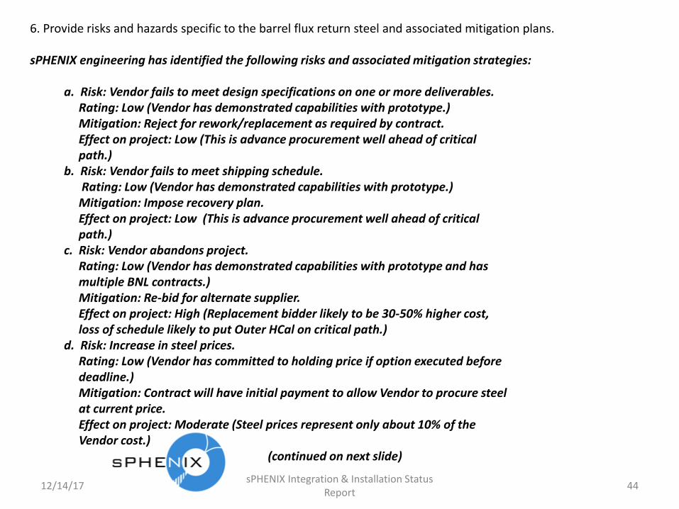
6. Provide risks and hazards specific to the barrel flux return steel and associated mitigation plans.
sPHENIX engineering has identified the following risks and associated mitigation strategies:
a. Risk: Vendor fails to meet design specifications on one or more deliverables.Rating: Low (Vendor has demonstrated capabilities with prototype.)Mitigation: Reject for rework/replacement as required by contract.Effect on project: Low (This is advance procurement well ahead of criticalpath.)
b. Risk: Vendor fails to meet shipping schedule.Rating: Low (Vendor has demonstrated capabilities with prototype.)Mitigation: Impose recovery plan.Effect on project: Low (This is advance procurement well ahead of critical path.)
c. Risk: Vendor abandons project.Rating: Low (Vendor has demonstrated capabilities with prototype and has multiple BNL contracts.)Mitigation: Re-bid for alternate supplier.Effect on project: High (Replacement bidder likely to be 30-50% higher cost, loss of schedule likely to put Outer HCal on critical path.)
d. Risk: Increase in steel prices.Rating: Low (Vendor has committed to holding price if option executed before deadline.)Mitigation: Contract will have initial payment to allow Vendor to procure steel at current price.Effect on project: Moderate (Steel prices represent only about 10% of the Vendor cost.)
(continued on next slide)

12/14/17sPHENIX Integration & Installation Status
Report45
e. Risk: Detector factory assembly (electronics fit up) or full detector assembly failure (Components don’t fit and/or sectors don’t line up.)
Rating: Medium (Procedure is not yet written, still conceptual). Mitigation: Extensive modeling and planned prototype fit-up efforts have
been/will be performed prior to production efforts. Detector factory construction is planned to be well off the critical path (over 12 months). Prototype detector assembly addressed gap tolerances for scintillator insertion,
which is already communicated to Streck’s and mitigated.Effect on project: Low (Minor adjustments during production will not put these tasks on critical path.
f. Risk: Engineering/design failure results in assembly structural failure.Rating: LowMitigation: Extensive modeling and planned prototype handling simulation efforts have been/will be performed prior to production efforts, structural analyses performed and checked by multiple experienced engineers, design reviews of components, assemblies and handling operations by sPHENIX internal and external reviewers.Effect on Project: High, would require redesign, new analyses, re-review
followed by rework/modification/new fabrication, which might take 6 months to a year to implement. Since all serial assembly work is by its nature on the critical path, then this failure would delay the project by 6 months to a year.
12/14/17sPHENIX Integration & Installation Status
Report46
g. Risk: Failure to exercise option for Outer HCal Steel Sector production.Rating: Medium to HighMitigation: (a) Develop response plan for review recommendations (this report), (b) schedule re-review prior to option expiration and (c) meet with Vendor to assure that all design and QA changes resulting from response plan are acceptable to vendor (already done, assuming this response plan is acceptable). Effect on Project: High (Replacement bidder likely to be 30-50% higher cost, loss of schedule likely to put Outer HCal on critical path.)
The above Risk analyses will be incorporated into the sPHENIX risk registry (see supporting document “sPHENIX Risk Registry”, available on request).

12/14/17sPHENIX Integration & Installation Status
Report47
7. Develop a clear QA/QC plan consistent with BNL SBMS and review with QMO.
sPHENIX engineering has worked with QA rep Chuck Gortakowski to create an sPHENIX QA Plan (see supporting document sP-SE.QAM.007), Configuration Management and Documentation Control Procedures (see supporting documents sP-SE.QAM.002 and sP-SE.QAM.003) and the SOW update (see supporting document sP-SOW.001).
All of these are posted on the Indico site: https://indico.bnl.gov/event/4501/

12/14/17sPHENIX Integration & Installation Status
Report48
8. Define responsibilities for the production/tests/acceptance in QA Plan.
sPHENIX engineering has incorporated into the SOW for the Outer HCal procurement (see sP-SOW.001, sections 3 and 4, and all subsections, posted on the Indico site: https://indico.bnl.gov/event/4501/) clear responsibilities for the Vendor production tests and inspection and for sPHENIX inspection and acceptance at the sPHENIX Outer HCalfactory. In addition sPHENIX engineers are currently preparing the Outer HCal factory general workplan (support document Outer HCal Factory Workplan (draft)).
(See Follow up questions/comments and responses on next slide)
12/14/17sPHENIX Integration & Installation Status
Report49
Lessard Follow up Comments / Questions
In today’s discussions, please indicate how responsibilities have been assigned for:
• developing the inspection and test criteria
Inspection at Vendor: SOW; Upon receipt at BNL: (Chris Pontieri) in Factory Work plan
• inspecting and testing each piece of the assembly against specifications
At Vendor: see SOW; At BNL: PHENIX Techs (Carter Biggs, lead, C. Pontieri, Engineer)
• inspecting for counterfeit parts
At Vendor: SOW; Upon receipt at BNL: PHENIX Techs (Carter Biggs, lead, C. Pontieri, Engineer)per BNL SBMS requirements as described in Factory workplan
• maintaining calibration records for measurement equipment used in the inspections and tests
At Vendor: see SOW; At BNL: PHENIX Techs (Carter Biggs, lead, C. Pontieri, Engineer)per BNL SBMS requirements as described in Factory workplan
• developing and maintaining procedures, related documentation, and records associated with the inspections and tests
At Vendor: SOW; At BNL: (Chris Pontieri) per sPHENIX general requirements developed by sPHENIX engineering management with advice and input from C. Gortakowski.

12/14/17sPHENIX Integration & Installation Status
Report50
9. Complete the C-AD design review questionnaire (C-AD OPM 13.06.1.a).
This has been completed (first drafts) for both the Outer HCal factory and the Outer HCal Assembly at 1008 (see supporting documents “Design Questionaire: Outer HCal Factory” and “Design Questionaire: Entire sPHENIX Detector at Bldg 1008” posted on the Indico site: https://indico.bnl.gov/event/4501/ ). Review of these documents has been initiated with CAD ESSH personnel.

12/14/17sPHENIX Integration & Installation Status
Report51
10. Establish a process to document, track and close out action items from internal and external reviews.
This already has been established for sPHENIX (see supporting document sPHENIX Recommendations Tracking System (RTS) available on request).

12/14/17sPHENIX Integration & Installation Status
Report52
11. Do not permit the date that the option must be exercised by for procuring the additional 32 sectors to be the driving factor for placing the order.
sPHENIX engineering agrees with this statement. The driving factors for this is, and always should be, (a) complete and accurate design, (b) reviewed and verified design analyses (structural, performance, etc. as appropriate, always with safety assessment built-in, (c) availability of funds, (d) schedule need, (e) added value of procurement timing and (f) other considerations, in that order. Acknowledging this recommendation from the committee, it is noted, that, once (a) through (d) have been satisfied, exercising the option prior to the contractual date has real value to sPHENIX and BNL (current estimate of over $100,000), and as such meeting the option exercising deadline, while not the driving factor, is nonetheless a significant factor.

12/14/17sPHENIX Integration & Installation Status
Report53
12. Provide a schedule for fabrication and delivery.
The schedule for the fabrication and delivery is dependent on the date the option is exercised, as prescribed in the updated SOW (posted on the Indico site: https://indico.bnl.gov/event/4501/ ) as follows:
Initial production unit (inspected, verified and accepted by sPHENIX): 16 weeks after option is exercised, the remaining 31 sectors to be delivered at a rate of one per week thereafter such that all 32 sectors are delivered and accepted at BNL 48 weeks after the production option is exercised. This has been incorporated into the P6 Resource Loaded Schedule. The OHCal steel procurement and delivery has been analyzed with respect to the critical path and shown to be over one year off the Critical Path, assuming the option is exercised by the option expiration date.
12/14/17sPHENIX Integration & Installation Status
Report54
13. Revise all affected drawings to require type 1020 steel.
This has already been done. The final released drawings are included with this report (see sPHENIX Outer HCaldrawing package. (15 Drawings, see SOW for list)).
These drawings are posted on the Indico web page: https://indico.bnl.gov/event/4501/

12/14/17sPHENIX Integration & Installation Status
Report55
14. Hold another review prior to procurement.
This is the purpose of today’s review.

12/14/17sPHENIX Integration & Installation Status
Report56
BACKUP
12/14/17sPHENIX Integration & Installation Status
Report57
Additional questions relating to reference documents:
For sPHENIX Document No. sP.EAR-2018-006 - Design and Structural Analyses of the sPHENIXSuperconducting Solenoid Magnet Interface with the Outer HCal Sector Steel Assembly1. What are the lateral alignment tolerances?
+/- 0.200
2. How do you ensure precision adjustment of magnet position using hydraulic jacks?
We plan to use fluorogold (Teflon impregnated fiberglass bonded to steel plates) bearings between the jacks and the magnet surface.(specs available on request)
Follow-up question: can hydraulic jack pressure be adjusted with sufficient precision?
Yes, we have routinely positioned the CM, MMS, WC and EC at PHENIX using hydraulic pistons.

12/14/17sPHENIX Integration & Installation Status
Report58
3. If hydraulic jacks are employed to adjust position, how is pressure maintained permanently?
The jacks we plan to use have a locking feature. (specs available on request)
Follow-up question: is this sufficiently reliable over the lifetime of the project?
Yes
4. What is the axial alignment tolerance?
+/- 0.200”
5. Are swivel leveling jacks used to only restrain, or to adjust position of magnet along beamline? If “adjust”, are hydraulic jack surfaces suitable for sliding? If “restrain”, then is magnet aligned in beam direction by crane?
Swivel jacks on the 8 radial positions are used only for lateral restraint. Jack screws aligned axially on hydraulic jack mounts will be used for longitudinal positioning adjustment.
Follow-up question: is the cryostat contact location and surface area the same or equivalent tothat used at SLAC?
Same as used at SLAC
12/14/17sPHENIX Integration & Installation Status
Report59
The following are responses to follow up questions coming from the 4 analyses conducted inresponse to item 45
Anerella Questions
Earlier questions:
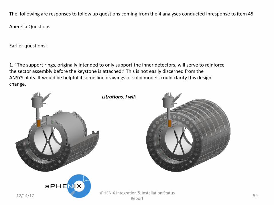
1. “The support rings, originally intended to only support the inner detectors, will serve to reinforcethe sector assembly before the keystone is attached.” This is not easily discerned from theANSYS plots. It would be helpful if some line drawings or solid models could clarify this designchange.
We are working on some drawings and illustrations. I will post some in the next day or so. (Did so)

12/14/17sPHENIX Integration & Installation Status
Report60
2. “It should be noted that there has been no change to the end plate design…” The presentation bySteve Bellavia at the review included assembly stresses in the end plates and dogbones (excerptsbelow) of the same order of magnitude, hence the general comment. Perhaps these are bothreconciled by (1) above:
We have modified the design of the dogbone (which no longer looks like a dogbone so we’ll just call it the splice plate) and pins, but not the endplate. The modified design, coupled with the internal supportreduces the stress in the endplate to give us a maximum stress less than 1/2 yield. For the splice platesand pins there we are planning to specify high strength steel so that these connecting pieces will havemaximum stresses well below 1/2 yield. I’ll also post some illustrations of this design as well.

12/14/17sPHENIX Integration & Installation Status
Report61
3. For the shipping analysis, “Three different loading conditions were considered: … and anacceleration of 1g in the vertical direction.” What was the basis for only using a 1g maximumvertical shipping acceleration?
Maximum stress in the part with 2 g’s vertical is less than 5ksi. If we scale that to 5 g’s its less than 12.5ksi. Still well below 1/2 yield.

12/14/17sPHENIX Integration & Installation Status
Report62
sPHENIX Document No. sP.EAR-2018-003 - sPHENIX Outer HCal Sector: Handling
1. “Sectors are lifted with a 21ft spreader beam to balance the load on the crane and avoid lifting fixture induced bending.” Please show this in use in conjunction with the “custom designed lifting fixture” to demonstrate that there is no bending effect when suspended from the crane.
When we say lifting fixture induced bending we mean bending due to lifting with slings at some angle due to no spreader bar or a spreader bar shorter than the sector. The spreader bar allows vertical lifting at both ends, hence no lifting fixture induced bending
Follow-up comment: Understood. The concern is the deflections of adjacent sectors themselves when hung from a crane or installed, and how those deflections may impact the installation of pins.
Deflections of horizontal sectors will be relieved by shimming at the center internal comb as sectors are laid onto previous installed sector and self aligned by splice plate cutouts for alignment pucks. This is best illustrated by walking through the conceptual installation.

12/14/17sPHENIX Integration & Installation Status
Report63
sPHENIX Document No. sP.EAR-2018-004 - sPHENIX Outer HCal Sector: Assembly
1. “The support rings, originally intended to only support the inner detectors, will serve toreinforce the sector assembly before the keystone is attached.” Please provide details.
Illustrations have been posted on the Indico site. We can provide a 3D dynamic look at these features during our meeting next week (today).
2. “Assembly” document does not discuss assembly methods or equipment. Please provide.
I have posted the remaining drawings and illustrations for assembly components not part of the procurement and for the lifting fixture components. There is no assembly procedure written as assembly is at least 2 years off. We do have an assembly concept that is better described in a dynamic 3D view at our meeting next week (today).
Follow-up comment: The committee needs to be assured that the assembly process has been thoroughly considered at the most detailed level as the safe and accurate completion of the assembly is dependent on the design that we have been asked to evaluate as well as the methods envisioned. The slides posted to indico in response to this concern suggest that some thought has been devoted to this issue, yet some questions arise regarding this latest information also (e.g., the new features between mating dogbones, while answering this concern, seem to over constrain the other pin details).
We will attempt to walk through the Installation concept step by step. We note that this procedure and similar design of dog bones and 4 pins per sector was utilized successfully for the D-Zero detector many years ago. Discussions with technicians and scientists involved in the assembly did not indicate any significant problems with the design and tolerancing. Our tolerancing and design is similar and we have improved on the installation procedure with a self alignment feature.

12/14/17sPHENIX Integration & Installation Status
Report64
sPHENIX Document No. sP.EAR-2018-005 - sPHENIX Outer HCal Sector: Operation1. Is 0.245 inch local vertical deflection acceptable for operation? Is it intended to align
sectors to this expected position or to compensate for the static deflection?
Yes, this is acceptable. We asked Kin Yip and Wuzheng Meng to consider the effect of a 0.375” deflection to be conservative. See Kin Yip’s comments posted on the Indico site. No compensation is required.

12/14/17sPHENIX Integration & Installation Status
Report65
Tuozzolo Questions
[Please address] the tolerance of the diameters of the 4 - 2.750” pins and how 4 holes in 3 different plates that are not match drilled or machined will align.
The holes on the plate are about 20” apart. From the thermal expansion analysis supplied there could be a .002” difference from the ± 8 F specification. How are the parts toleranced to compensate for that?
The tolerance of the pin/dogbone/endplate is a minimum of 0.005”. Drawing tolerance stackup has been calculated including worst case thermal expansion (.002”)
Follow-up comment/question: The committee needs to understand what that means. How does thetolerance stack up occur: the distance between the holes, the diameter of the hole, and the diameterof the pin? What is the tolerance on longitudinal twist of the sector – if you can install the dog boneon one end and there is 0.3 mRad twist in the sector, the pins will not go in.
We have carefully considered the tolerance stackup for drawing tolerances between sectors. Twist will be taken up by shimming using weight of sectors. See the step by step installation described above.
12/14/17sPHENIX Integration & Installation Status
Report66
The ANSYS analysis below indicates ~ .6 mm/.024” deflection of the assembled HCAL at the topends where the “dog bone” links are. How do the dog bone links compensate for that difference duringassembly?
The ANSYS analysis shows a 0.24” deflection of the entire assembly. This is not a relative distance fromone sector to another. Each sector will be aligned in place as it’s installed and we will be able to locatethe sectors to each other to install the pins. Your reference to 0.24” deflection mistakenly looks at it as arelative deflection. It is an absolute deflection related to the reference plane. Both end plates we arejoining will deflect a similar amount and in the same direction, so not so much relatively.
Follow-up comment/question: The committee needs to understand how these holes are going to bealigned while the sectors are hanging from the fixtures from a crane hook which does not haveaccurate control.
This is best illustrated in the step by step installation discussion described above. Again we note that this is not a unique concept having been accomplished similarly for the D-Zero detector.

12/14/17sPHENIX Integration & Installation Status
Report67
The last top HCal sector will be hanging from the lifting fixture; the adjacent 31 assembled HCAL sectors will be tied together with dog bones. Again from the ANSYS analysis the ends of the sectors will not be loaded differently and will not be parallel. What is the difference and how will the pins be driven in.
The last HCAL sector will be hanging from the lifting fixture in the vertical position where the deflection has a minimal effect on the endplates. The adjoining sector would have similar deflection.
Follow-up comment/question: The committee needs to understand the shape of the HCAL steel before the last sector goes into place. It is not the “perfect circle” modeled in ANSYS. How much difference is expected, how small will the pins be?
With the tolerances specified installing the pins will not be an issue. We will have a number of undersizedpins available in the event there is an unforeseen tolerance stack-up or increased/decreased deflection.
Follow-up comment/question: This raises 2 concerns. If undersized pins are used early in the assembly process, the “perfect circle” will be quickly lost and other methods will be needed to compensate and align. Also smaller pins will result in more localized stresses on the pin and mating plate. Will that localized stress be within the safety factor?
The HCal steel modeled in ANSYS is not a perfect circle. It is deflected, but the deflection is limited by the internal support to a near perfect circle, with adjustments made as the assembly is built. Prior to inserting the last sector hydraulic pistons will be used to create additional separation. The final pucks used will have a tapered leading edge to allow the final pucks to be driven in (not captured as in previous sector installation steps) to force the sectors into near alignment before the pistons are retracted which will allow the self aligning feature to get the last 2 pin holes aligned. We will only have slightly undersized pins (~.010” under sized) in case the last 4 pin holes end slightly out of alignment. The installation steps described above should illustrate this. The change in localized stress is insignificant in these pins.

12/14/17sPHENIX Integration & Installation Status
Report68
(From Charlie Folz) In discussing other elements of the newly submitted documentation, I also share with Joe concerns regarding the assembly; particularly with regard to the fitting of large diameter pins with vary small tolerance holes and potentially significant tolerance stacking issues. While it appears that some progress has been made regarding the structural analysis of the assembly, this issue remains to be addressed.
Once again, we note that the design employed here is not unique, novel or new, and has been employed successfully by members of our immediate staff in the D-Zero detector design with similar tolerances and design features. The design of the HCal sector components has not changed since we presented the design at the design review, January 31 of this year. We were confident of the design at that time, but recognized that there was some risk that fleshing out the assembly procedure, the design of the connecting components (pins and splice plates) and lifting fixture components could require minor modifications to the sector assembly, but we believed that risk was very small. All additional analyses performed since that time reinforces our opinion from that time and we believe it reduces that risk to insignificant.

12/14/17sPHENIX Integration & Installation Status
Report69
Additional Recommendations
Design Details and Drawings
(Recommendation# 15): The need for temperature control or monitoring should be evaluated.
Vendor (Streck’s) was contacted to determine their ability to control temperatures in their fabrication and inspection facilities. The response was 72 +/-8 deg F. Calculations were then performed to determine the potential effect on tolerances this temperature variation could imply (see supporting document sP-DOC-2018-001). Conclusion: 72 +/-8 degF is an acceptable specification. This has been added to all drawings and the SOW.
(Recommendation# 16): Consider redesigning the pinning of adjacent sectors using a single larger pin to facilitate installation while avoiding interferences, and using perhaps a secondary pin or key in a slotted hole purely for rotational alignment. It is understood that this would represent significant change to both design and assembly processes. Alternately other methods may be considered which preclude the use of individual dog bones between sectors.
sPHENIX engineering has concluded its analyses of the Outer HCal sector under all conditions of handling, shipping, assembly and operation. The design of the Outer HCal sector as presented at the January 31, 2018 design review has now been demonstrated to be appropriate and adequate for all conditions. The suggestions made in this recommendation have been considered, as suggested, but rejected as adding unnecessary complexity and cost (see item #4 in the Pre-Award Recommendation section of this report for further discussion and support documentation).

12/14/17sPHENIX Integration & Installation Status
Report70
(Recommendation# 17): Consider design changes which obviate the need for position adjustments based on survey inspections.
The same comments made for the previous recommendation (4.1.2) apply here.
(Recommendation# 18): Complete interface designs for magnet cryostat and end plates.
The response to Pre-Award Recommendation # 1 fully addresses this recommendation.
Steel Performance as Flux Return
(Recommendation# 19): Analyze the effects on magnetic performance of positional errors due to assembly tolerances and gravity loads.
This recommendation is currently being analyzed by Kin Yip. His response will be documented in support document “Effects of Outer HCal structural elastic deformation due to full operational loading”.

12/14/17sPHENIX Integration & Installation Status
Report71
Structural Design Calculations
(Recommendation# 20): Revise the design to achieve the stated goal of a safety factor of 2X with regard to yield strength during operation.
The response to Pre-Award Recommendation #4, above addresses this. sPHENIX engineering notes that it was always intended that a safety factor of 2.0 with respect to yield stress is and always was not only a design goal, but a design requirement. These design efforts have now been completed and are documented in supporting documents sP.EAR-2018-002, sP.EAR-2018-003, sP.EAR-2018-004 and sP.EAR-2018-005.
(Recommendation# 21): Revise the design or assembly to eliminate the yielding of components during assembly.
This recommendation is also covered by the response to Pre-Award Recommendation #4 and in supporting documents sP.EAR-2018-002, sP.EAR-2018-003, sP.EAR-2018-004 and sP.EAR-2018-005.

12/14/17sPHENIX Integration & Installation Status
Report72
(Recommendation# 22): Perform an analysis of mechanical stresses due to accelerations during shipping (magnitudes and directions are dependent on equipment and methods of shipment).
These calculations have been performed (see response to Pre-Award Recommendation #4 and, specifically, supporting document sP.EAR-2018-002).
(Recommendation# 23): Evaluate magnetic forces on the steel and determine if structural analysis is warranted.
These calculations have been performed (see response to Pre-Award Recommendation #4 and, specifically, supporting document sP.EAR-2018-005).
(Recommendation# 24): Revise all affected drawings to require type 1020 steel.
This recommendation is the same as Pre-Award Recommendation #13. As indicated in the response to that recommendation, this is done, as recommended.

12/14/17sPHENIX Integration & Installation Status
Report73
Handling, Assembly and Installation Plans
(Recommendation# 25): Evaluate if temperature control or monitoring is required and develop a plan accordingly.
This is essentially the same recommendation as Recommendation #15. See the comments for that recommendation.
(Recommendation# 26): Consider revising design (see “Design” recommendations above) or revising assembly process to temporarily index and support each sector in proper position until the complete assembly arch is complete.
This is essentially the same recommendation as #16. See the comments for that recommendation.
(Recommendation# 27): Provide details of method for adjusting sectors into final position using surveying as indicated.
This is essentially covered by recommendation #16. See the comments for that recommendation.

12/14/17sPHENIX Integration & Installation Status
Report74
(Recommendation# 28): Consider completion of the Critical Lift Evaluation Form (CLEF) in order to classify the proposed lift. Also, complete and submit a lifting fixture certification.
This is done. Supporting documents Critical Lift Evaluation Form (CLEF) and sP.EAR-2018-007 satisfy this recommendation. Note: a lifting fixture certification is issued by the BNL lifting safety committee. This is the documentation submitted to the committee to request certification. sPHENIX expects to receive certification in a few weeks, well before receipt of the first production sector.
(Note: follow up questions on this response were received the next slide addresses these.)
12/14/17sPHENIX Integration & Installation Status
Report75
Folz Comments / Questions
To this point, I have looked over the Critical Lift Evaluation Form (CLEF) submitted with the documentation package and find that it is lacking. The CLEF provided does not describe any particular lift evolution or procedure and does not state whether the proposed lift or series of lifts have been categorized at all. I would expect to see a description of the proposed lift or lift sequences and a conclusion regarding into what category these lifts have been placed. If categorized as a Critical or Pre-Engineered Lift, then significant further detail is expected.
We have tried to address Charlie’s concerns and revised and reposted the lifting fixture analysis and the CLEF with more support documents. We have categorized the lifts of the sectors as “ordinary” but Mike Gaffney may bump that up. We will work with Mike to get this lifting fixture approved.
I also found that the analysis provided for the spreader bar for lifting the HCAL steel does not conform to the ASME Standard for Design of Below-the-Hook Lifting Devices (ASME BTH). Before using any lifting fixture here at BNL these devices are to be certified and proof tested by the manufacturer (who will provide a certificate to that effect). Alternatively, an analysis according to the ASME BTH prescriptive standard may be submitted to the BNL Lifting Safety Committee and then the device is proof tested and witnessed (then NDT’d) here on site. The ASME BTH standard is very specific regarding how to perform the analysis and what safety factors are required based on the intended service category of the device.
We are currently working on getting the lifting fixture evaluated for approval by the lifting safety committee. We have already had some discussions with Mike Gaffney concerning this and expect to submit our paperwork to him this week. Please note that Charlie seems to be under the impression that we are designing the spreader bar. This is not the case, the spreader bar is a commercially purchased component which we have already procured, it has been tested and certified by the vendor and has already been inspected and approved by the lifting safety committee.
12/14/17sPHENIX Integration & Installation Status
Report76
QA, QC and Testing Plans
(Recommendation# 29): Have QMO review and provide input to the SOW, configuration control and documentation control documents, and drawings.
sPHENIX engineering has been working with Chuck Gortakowski to update the SOW, Configuration Management and Documentation Control Procedures for sPHENIX in general and, in the case of the SOW, for the Outer HCal steel sectors in particular. See items 2 and 3 in the Pre-Award Recommendation section for more details. Chuck has also reviewed and signed off on all of the drawings.
Recommendation# 30): Determine how the vendor will comply with ISO9001 at each of the two manufacturing locations.
The VENDOR under contract for the sPHENIX Outer HCal steel sectors is a long time supplier of subcontracted machined metal arts for BNL, has been vetted by BNL QA and has a reputation for delivering quality components on schedule. Streck’s Quality Control Manual and a filled out BNL Supplier Survey form were solicited from Streck’s by sPHENIX QA rep Chuck Gortakowski to demonstrate compliance with the relevant sections of ISO 9001. It is noted that Streck’s is not and never has been ISO9001 certified. These documents are Vendor Proprietary labeled but may be made available for controlled review on request.

12/14/17sPHENIX Integration & Installation Status
Report77
(Recommendation# 31): Consider a QA pre-award site visit to assess risks associated with ISO9001 compliance in lieu of ISO9001 certification, and also to confirm adherence to other requirements.
See the previous item recommendation #30 for relevant comments. Chuck Gortakowski, sPHENIX QA rep, has determined that a pre-Award site visit is unnecessary, but a post-award site visit will be scheduled prior to assembly of the production verification sector.
(Recommendation# 32): Provide an updated SOW for the production procurement, including:
a. Provide clear complete inspection requirements.b. Provide detailed schedule requirements for production and delivery
This has been prepared. See item 3 in the Pre-Award Recommendation section and the SOW itself.

12/14/17sPHENIX Integration & Installation Status
Report78
Procurement Documents and Contract Implementation
(Recommendation# 34): The contract to procure the 32 additional sectors should only be placed after all of the design, assembly and QA issues identified in this report have been evaluated and addressed to the satisfaction of this review committee.
The SOW and drawing package have been revised and rewritten to reflect the QA and contractual requirements of the production option. Also see comments for Pre-Award Recommendations # 2, 3, 7, 8, 10 and 13 and comments on additional recommendations # 15, 18, 19, 20, and 21 for detailed sPHENIX responses to the QA issues raised by the committee’s report. It should be noted that the contract is already in place; the issues at hand are revising and reworking of the existing contract to the satisfaction of the committee to allow sPHENIX to execute the production option in the existing contract.

12/14/17sPHENIX Integration & Installation Status
Report79
(Recommendation# 31): Consider conducting discussions with the vendor to determine the cost and schedule impact of not executing the procurement option in April 2018
This is already addressed in the response to item 11 of the Pre-Award Recommendations. During discussions with the Vendor, it was indicated that recent events have caused the price of steel to increase by 25%. The Vendor indicated that they would absorb the cost increase if the contract option were exercised prior to the contractual deadline. sPHENIX engineering estimates the material cost represents about 10% of the overall contract cost (the rest is machining, assembly, finishing, shipping and administrative costs. Given those estimated percentages, the potential increase in cost for not exercising the option would be a minimum of $100,000. In addition, it is likely that there would be a significant schedule impact of 1-6 months if the contract can be renegotiated without rebidding, and 6-12 months if the contract must be rebid. The Vendor has already provided an estimate of the cost to incorporate minor design changes as presented at the review, and BNL procurement has indicated that these costs are allowable within procurement guidelines, without re-bidding the contract.

12/14/17sPHENIX Integration & Installation Status
Report80
sPHENIX Magnet and Flux Return Utility for EIC
There were no specific recommendations for this presentation topic from the January 31, 2017 design review. The committee did rightfully comment, however, that
“With the information presented it was not possible to evaluate whether the design is compatible with the requirements of a EiC detector.”
sPHENIX engineering agrees with this statement and furthermore notes that while scientists may speculate on the suitability of the sPHENIX detector for some future EiCdetector, engineers must deal with firm specifications on which to base their designs. No such specifications have been provided to sPHENIX engineers, rather the contrary has been true; sPHENIX engineering has provided detailed specifications on the current state of design of sPHENIX components to EiC scientists at various times during the design process to allow them to evaluate the relative compatibility with a future EiC detector. To the extent that EiC scientists have made design requests to sPHENIX engineers, their requests have been complied with. sPHENIX has also instituted an office of system integration, in which the chairman of this office is a contributor to the EiC efforts and has attempted,
12/14/17sPHENIX Integration & Installation Status
Report81
where appropriate and to the extent feasible, to assure that the design and integration parameters of the various sPHENIX detectors, including the Outer HCal, are compatible with the current EiC concept. At this point in time the only specification concepts relevant to the Outer HCal steel design are:
1. An EiC detector is expected to utilize the BABAR superconducting solenoid magnet at the same field as sPHENIX. In this case the sPHENIX Outer HCal steel would be suitable as a flux return.
2. Re-purposing of the inner detectors, or new detectors that would fit inside the BABAR magnet, are expected to be needed. The sPHENIX Outer HCal steel would be compatible with that, as it is for sPHENIX.
3. Additional detectors and magnetic components upstream and downstream of the BABAR magnet are expected to be needed. The sPHENIX Outer HCal steel would be compatible with that, based on initial modeling by EiC scientists with conceptual illustrations from sPHENIX engineering. We also note in passing that the Particle Identification (PID) detectors for the hadron-going direction for an EIC detector are predominantly forward of η=1.1 (i.e. at polar angles less than 37 degrees). The Barrel Steel does not obscure this area and thus
12/14/17sPHENIX Integration & Installation Status
Report82
would be compatible with the versions of such key detectors presented at the EIC Detector R&D meetings to date.
4. The addition of an electron ring may require moving the BABAR magnet and consequently the Outer HCal steel approximately 6 feet towards the center of the RHIC beam path. The sPHENIX Outer HCal steel would be compatible with that as there is enough clearance from the sPHENIX shield wall to make such a move. (It should be noted that the current configuration of the sPHENIX rail system in the sPHENIX interaction region (IR) would require some modification to accomplish this move, but that would not require modification of the Outer HCal steel.)
5. There are no other specific design details for an EiC detector that sPHENIX engineering is aware of that would be incompatible with an EiC detector.
sPHENIX engineers will continue to work with EiC scientists to attempt to maintain compatibility as far as possible. sPHENIX engineers are not, however, designing an EiCdetector. The sPHENIX detector is meant to stand on its own merits whether or not it is ever used as an EiC detector.

12/14/17sPHENIX Integration & Installation Status
Report83
Conclusions
sPHENIX Engineering appreciates the time and effort put in by the January 31, 2018 Outer HCal sector steel design and procurement review committee to evaluate, comment and recommend specific positive actions to assure a successful design, fabrication and acceptance effort for the sPHENIX Outer HCal sector steel. The findings, comments and recommendations of the committee represent, we believe, a thorough and sincere attempt to provide design guidance and share their technical expertise with the sPHENIX engineering staff. In turn, sPHENIX engineering believes we have made a thorough and comprehensive effort to address and/or incorporate all recommendations as completely as possible. In summary:
1. We have provided a detailed description of the magnet to barrel steel interface.2. We have provided updated and released configuration control documents.3. We have provided an updated SOW.4. We have provided updated splice plate and pin design and we will request to
review these plates and pins in a separate review.5. We have provided structural analysis for all anticipated cases (assembly, handling,
seismic, shipping, magnetic loading and appropriate combinations thereof).

12/14/17sPHENIX Integration & Installation Status
Report84
6. We have provided a list of risks with appropriate analyses and mitigation plans.7. We have met with BNL QMO and are continuing to work with them to document
our QA/QC plans.8. We have defined the responsibilities for production test plans and acceptance.9. We have completed the C-AD design review questionnaires for both the Outer
HCal factory and the overall sPHENIX project.10. We have established a review recommendation tracking process.11. We accept that the option expiration date should not be the driving factor for
exercising the option.12. We have provided the proposed fabrication and delivery schedule.13. We have revised all drawings to require type 1020 steel.14. We have requested a follow up review to the January 31, 2018 review. (This
review, today)
In addition we have provided what we believe is a satisfactory and positive response to all of the other 20 recommendations from the committee.