outdoor voltage transformers type: tdo 6, tjo 6, tjo 7 ... · type: tdo 6, tjo 6, tjo 7, vog-24,...
TRANSCRIPT

Type: TDO 6, TJO 6, TJO 7, VOG-24, VOL-24, VOL-40.5Instruction for installation, use and maintenance
Outdoor voltage transformers

2 Instruction manual
1. General description 42. Service conditions 43. Technical details 54. Instruction for installation 64.1 General 64.2 Checking voltage transformers upon arrival 64.3 Preparations before installation of voltage transformers 64.4 Safety instructions 64.5 Mounting 74.5.1 Primary connection 74.5.2 Secondary connections 85. Maintenance and overviews during exploitation 105.1 Maintenance 105.2 Overviews during exploitation 106. Instruction for use 107. Package, transport and storage 118. Disposal 119. Voltage transformer handling 1110. Normative references 1211. Wiring diagram examples 1212. Connections of voltage transformers – examples 1413. Dimensional Drawings 17TDO 6 17TJO 6 18TJO 7 19VOG-24 20VOL-24 21VOL-40.5 22
Content

Instruction manual 3
Safety instructions
Warning – please read the notes which are marked with this sign carefully.
Installation, connection, operation and maintenance should be carried out by authorized personnel only.
This manual should always be accessible for the user’s personnel.
Voltage transformers are high voltage devices and must be used according to the appropriate safety rules!

4 Instruction manual
1. General descriptionThe voltage transformers are designed to supply measurement and protection circuits in high voltage power networks (with admissible voltage up to 40.5 kV and frequency 50 Hz or 60 Hz).
The instruction includes the following types of voltage transformers:– TJO 6, TJO 7, VOG-24– voltage transformers single-pole,– TDO 6, VOL-24, VOL-40.5 – voltage transformers double-pole.
Design versions may differ depending on:– dimensions,– rated primary voltage (insulation level),– secondary voltage,– rated power in given accuracy class,– thermal burden.
Examples of voltage transformers design (TDO 6, TJO 7 type) are shown in the Figure No. 1 and 2.
2. Service conditionsThe voltage transformers should be mounted in outdoor conditions where the ambient air may be polluted by dust, smoke, corrosive cases, vapours or salt. The voltage transformers are designed for standard ambient temperature between -40°C and +40°C and altitude lower than 1000 m above the sea level. The average value of the ambient temperature, measured over a period of 24 hours, should not exceed 35°C. The transformers may be used also in higher or lower ambient temperatures and higher altitudes when agreed between the manufacturer and purchaser.
Figure 1. An example of the construction of a double-pole transformer (based on transformer TDO 6)
Figure 2. An example of the construction of a single-pole transformer (based on transformer TJO 7)
1 – Primary winding, 2 – Secondary Winding, 3 – Magnetic core, 4 – Epoxy resin housing, insulation 5 – Terminal primary winding, 6 – Terminal box of the terminals secondary windings, 7 – Steel baseplate with earthing terminal
1
5
5
3
7
7
2
6
4
1
5
3
7
2
6
4

Instruction manual 5
3. Technical detailsThe technical details for each individual voltage transformer are indicated on the rating plate fastened on the voltage transformer. Parameter values indicated on the rating plate must not be exceeded
Description markings on the nameplate:
SN: 1YMP015TJO00460
Type: TJO 7Order No.:548856#13033000:V3/110:V3/110:3 V/V/V
Prod.No.:30218656#12
SN: 1YMP015TJO00460
Type: TJO 7Order No.:548856#13033000:V3/110:V3/110:3 V/V/V 1.9/8h
f:50Hz Amb.T.:40°C
a-n 33000:V3/110:V3 V/V 50VA cl.0.5da-dn 33000:V3/110:3 V/V 100VA cl.6P
36/70/170kVIEC 61869-3
700VAMade by ABB
t.cl.E2015
Figure 3a. Example of VT’s rating plate (TJO 7 type).
Figure 3b. Example of VT's rating plate (VOL-40.5).
SN: 1YMP015TJO00460 Serial number
Type: TJO 7 Transformer type code
f: 50 [Hz] Rated frequency
33000:√3/100:√3/100:3 [V] Rated voltage ratio
a-n Terminal marking for first secondary winding
da-dnTerminal marking for auxiliary secondary winding (for open delta connection)
50VA, 100 [VA] Rated power
0.5, 6P Accuracy classes
36/70/170[kV]Highest voltage for equipment / power-frequency withstand voltage / rated lightning-impulse voltage
IEC 61869-3 Standards
2015 Year of production
t.cl.E Temperature class
700 [VA] Thermal limiting output
1.9/8h Voltage factor
Amb.T.: 40°C Ambient temperature
Order No.: 548856#130 Order number
Voltage transformers weight
Voltage transformer type Weight [kg]
VOG-24 app. 39
VOL-24 app. 43
VOL-40.5 app. 70
TJO 7 app. 55
TJO 6 app. 57
TDO 6 app. 60

6 Instruction manual
4. Instruction for installation
4.1 GeneralA voltage transformer is a piece of electrical equipment and its electrical installation shall be done by skilled person only. Observe the provisions of local legislation regarding the minimum age and the competence criteria for personnel working with or in vicinity of electrical installations.If local legislation is not applicable, the guidelines set forth in EN 50110-1 shall be observed.
4.2 Checking voltage transformers upon arrivalInspection shall be made upon arrival of voltage transformer for any signs of damage or tampering incurred during shipment.
Make sure that voltage transformer parameters indicated on the rating plate comply with the parameters specified on the order!
If:– there are any damages in the shipment,– voltage transformer has been damaged,– or voltage transformer ratings do not comply with order
specification, notify the carrier and contact the voltage transformer manufacturer. Keep the written record of damages until complaint resolution.
4.3 Preparations before installation of voltage transformersPerform a visual inspection of the voltage transformer prior to installation paying particular attention to the following points:
– cast resin (enclosure) is in good condition,– voltage transformer terminals and surfaces of housing and base
are clean and without visible mechanical damages,– there are no signs of moisture on the voltage transformer; in
case of visible signs of moisture, the voltage transformer must be dried,
– voltage transformer ratings comply with technical specification of connection.
Prior to installation of the voltage transformer perform the following measurements: a) measurement of insulation resistance of primary
winding: – insulation resistance of unearthed transformer (with
two insulated primary terminals) shall not be lower than 1000 MΩ, use 2,5 kV coil megaohmmeter to measure the resistance between short-circuited terminals of primary winding and base,
– insulation resistance of earthed transformer (with one insulated primary terminal) shall not be lower than 200 MΩ. Use 1 kV coil megaohmmeter to measure the resistance between short-circuited terminals of primary winding and base.
Prior to measurements of insulation resistance for earthed transformer (with one insulated primary ter-minal) remove an earthing screw from “N” terminal in terminal strip and remember to reattach it after completing measurements.
b) measurement of insulation resistance of secondary windings:
– insulation resistance of secondary windings insulation shall not be lower than 50 MΩ. Use 1 kV coil megaohmmeter for measurements.
Prior to measurements of insulation resistance of se-condary windings remove earthing screws in one of the terminals of each secondary winding, if screwed in. Reattach these earthing screws and ground one of the terminals according to voltage transformer connection diagrams.
4.4 Safety instructionsa) Installed voltage transformer shall be always considered as part
of interconnected circuit. Never attempt to touch the leads, terminals or other parts of the voltage transformer unless they are known to be properly connected and ground.
b) Always ground the metal base of voltage transformer.c) If secondary winding is earthed at several points, only the same
terminal of secondary winding may be used for grounding. Check with care if both terminals of the same secondary winding are not grounded by accident. Grounding both terminals of secondary winding can result in damage of voltage transformer over a short period of time. Any claims for resulting transformer damages will be void.
d) If auxiliary secondary windings of earthed transformers (single-pole insulated) are connected to open delta, only one node of open delta circuit may be earthed.
e) If two unearthed voltage transformers (double-pole insulated) operate in V-connection, only one of the two terminals of secondary winding may be earthed.
Instruction manual 7
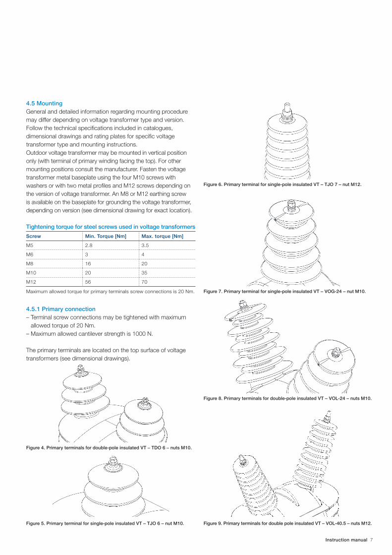
4.5 MountingGeneral and detailed information regarding mounting procedure may differ depending on voltage transformer type and version. Follow the technical specifications included in catalogues, dimensional drawings and rating plates for specific voltage transformer type and mounting instructions.Outdoor voltage transformer may be mounted in vertical position only (with terminal of primary winding facing the top). For other mounting positions consult the manufacturer. Fasten the voltage transformer metal baseplate using the four M10 screws with washers or with two metal profiles and M12 screws depending on the version of voltage transformer. An M8 or M12 earthing screw is available on the baseplate for grounding the voltage transformer, depending on version (see dimensional drawing for exact location).
Tightening torque for steel screws used in voltage transformers
Screw Min. Torque [Nm] Max. torque [Nm]
M5 2.8 3.5
M6 3 4
M8 16 20
M10 20 35
M12 56 70
Maximum allowed torque for primary terminals screw connections is 20 Nm.
4.5.1 Primary connection– Terminal screw connections may be tightened with maximum
allowed torque of 20 Nm.– Maximum allowed cantilever strength is 1000 N.
The primary terminals are located on the top surface of voltage transformers (see dimensional drawings).
Figure 4. Primary terminals for double-pole insulated VT – TDO 6 – nuts M10.
Figure 5. Primary terminal for single-pole insulated VT – TJO 6 – nut M10.
Figure 6. Primary terminal for single-pole insulated VT – TJO 7 – nut M12.
Figure 7. Primary terminal for single-pole insulated VT – VOG-24 – nut M10.
Figure 8. Primary terminals for double-pole insulated VT – VOL-24 – nuts M10.
Figure 9. Primary terminals for double pole insulated VT – VOL-40.5 – nuts M12.

8 Instruction manual
4.5.2 Secondary connections Terminals, terminal screws, nuts and washers are made of brass or stainless steel. The terminal box is provided with one or two PG21 cable gland. The secondary terminals are provided with M6 screws for wiring connections. The cover of the terminal box is provided with lead seal lock. In outdoor voltage transformers degree of IP54 protection for terminal boxes.
Figure 10. Examples of voltage transformers terminal boxes – TDO 6.
Fig. 10a. Designation of the secondary windings
Figure 11. Examples of voltage transformers terminal boxes – TJO 6.
Fig.11a. Designation of the secondary windings
Figure 12. Examples of voltage transformers terminal boxes – TJO 7.
Fig.12a Designation of the secondary windings

Instruction manual 9
Figure 13. Examples of voltage transformers terminal boxes – VOG-24.
Fig.13a. Designation of the secondary windings
Figure 14. Examples of voltage transformers terminal boxes – VOL-24.
Fig.14a. Designation of the secondary windings
Figure 15. Examples of voltage transformers terminal boxes with fuse as option – VOL-40.5.

10 Instruction manual
5. Maintenance and overviews during exploitation.
5.1 MaintenanceExcessive dust or other kind of pollution must be brushed off the transformer. Polluted transformers can be cleaned with spirit, petrol or toluene. Traces of arcs and minor surface damages can be easily removed with sandpaper after which the surface is to be treated by applying a thin layer of silicone paste on it. Instruction for repairing greater surface damages must be requested from the manufacturer.
5.2 Overviews during exploitationMedium voltage instrument transformers in resin insulation are maintenance-free. However, because of work under different environmental conditions during the transformer operation it is advisable to carry out:– overview of the instrument transformer during operation – only
visual control,– overview of the instrument transformer disconnected from
power supply.
Time periods between inspections is regulated by standards, by operation and maintenance manual of switchgears or user requirements.
Overview of the instrument transformer during operation The review is based on visual control in accordance with the principles of safety. During the inspection should pay attention to:– condition of resin body,– condition of primary terminals,– condition of support structures.
Overview of the instrument transformer disconnected from power supply The overview should be done every time before restarting. The overview should include:– cleaning the surface of instrument transformer,– checking condition of the transformer resin body surface,– checking condition of mounting screws and checking the
condition of all electrical connections (on primary and secondary terminals and earthing terminals),
– measurement of main insulation resistance,– measurement of secondary winding insulation resistance.
Cut off the power supply of transformer before attempting cleaning or repairing operations.
6. Instruction for use
The main tasks of voltage transformers are:– to transform voltages from a usually high value to a value easy to
handle for relays and instruments, while maintaining appropriate accuracy class, and to power supply to the metering circuit,
– to insulate the metering circuit from the primary high voltage system,
– supply other low voltage devices do not require a high standard of accuracy, such as disconnectors drives
For applications that use a power supply transformer, the transformer is recommended to use double-pole voltage transformer. In the case of single-pole voltage transformer secondary side can rise to 190% of rated voltage, which can cause permanent damage to the powered device and the transformer. Using double-pole voltage transformer should be one of the ends secondary winding grounded. An example of such a connection is shown below in Fig. 16.
Using voltage transformers for purposes other than described above is forbidden, if not otherwise agreed with its manufacturer.
Figure.16. An example of connecting the receiver to the secondary terminal winding of the double-pole voltage transformer.

Instruction manual 11
7. Package, transport and storage
Admissible temperature range for storage and transport of voltage transformers is -40°C to +70°C. Voltage transformers must be protected from exposure to direct sunlight during transport and storage. Voltage transformers shipped for domestic customers are packed in wooden crates or according to customer’s specification. Voltage transformers shipped for abroad customers are packed in wooden crates. Voltage transformer should be shipped in position according to symbols and marks indicated on its packing case and protected against weather conditions. They should be stored in dry and clean places, protected from direct exposure to precipitation and solar radiation
8. Disposal
Materials used in instrument transformers are considered as materials without dangerous environmental impact and materials are not toxic. Disposal of instrument transformers is controlled by national legislation of communal waste.
9. Voltage transformer handling
Voltage transformers equipped with eye bolts may be handled by means of chains and crane. Screw the eye bolts directly to the U profile or the baseplate and attach to the crane’s hook using chains. This handling method is recommended for the majority of voltage transformers equipped with baseplate and weight exceeding 25 kg, mainly types: TDO 6, TJO 6, TJO 7, VOG-24, VOL-24, VOL-40.5 (see figure 17).
Figure 17. Example of handling voltage transformer VOL-24.

12 Instruction manual
Load capacity for chains/loops/crane must be no less than 200 kg. Always make sure that chains/loops are properly and safely attached to the crane’s hook and that the voltage transformer is properly secured.
Observe the work safety rules during voltage trans-former handling operations. Never stay under the suspended loads. Always make sure that the voltage transformer is safely attached to the crane’s hook and there is no risk of load falling or tipping over.
10. Normative references
Voltage transformers are: designed, tested and manufactured according to international or national standards specified by cus-tomers and confirmed by manufacturer. Normative reference for a given voltage transformer is always indicated on the transformer’s rating plate.
Standard examples:IEC 61869-1; IEC 61869-3; IEC 60044-2; GOST 1983-2001.
On requests, voltage transformers may be designed and manufactured in accordance with other revisions of standard or standards specified above upon a prior agreement between manufacturer and purchaser.
11. Wiring diagram examples
Figure 18. Electric schemes
a) Single-pole insulated voltage transformer with one secondary winding
b) Single-pole insulated voltage transformer with one secondary, tapped winding
c) Single-pole insulated voltage transformer with one secondary winding and one auxiliary winding (for open delta connection)
d) Single-pole insulated voltage transformer with two secondary, tapped windings

Instruction manual 13
e) Single-pole insulated voltage transformer with two secondary windings and one auxiliary winding
f) Single-pole insulated voltage transformer with two secondary windings
g) Single-pole insulated voltage transformer with three secondary windings
h) Single-pole insulated voltage transformer with two secondary, tapped wind-ings, one of which is auxiliary winding (for open delta connection)
i) Double-pole insulated voltage transformer with one secondary winding
j) Double-pole insulated voltage transformer with one secondary, tapped winding
k) Double-pole insulated voltage transformer with two secondary windings
l) Double-pole insulated voltage transformer with two secondary, tapped windings

14 Instruction manual
12. Connections of voltage transformers - examples
Connection name Wiring diagram Application
With one
double-pole transformer
Line voltage measurement.
Both poles of the transformer have to be fully
insulated.
With one
single-pole transformer
Line to ground voltage measurement.
One pole of the transformer should be fully
insulated.
Star connection with
broken delta system
Line to ground voltage and residual voltage
measurement.
One pole of the transformer should be insulated.
Star connection
Line to line voltage measurement.
Connection may have an broken delta system for
residual voltage measurement.
One pole of the transformer should be insulated.

Instruction manual 15
Star connection Line to line and line to ground voltage
measurement.
Connection may have an broken delta for residual
voltage measurement.
One pole of the transformer should be insulated.
Receivers are connected for line to ground
measurement.
Both poles of the transformer have to be fully
insulated.
Receivers are connected for line to line voltage
measurement.
Both poles of the transformer have to be fully
insulated.
Connection name Wiring diagram Application

16 Instruction manual
Two receivers are connected for line to line
voltage measurement.
Both poles of the transformer have to be fully
insulated.
Connection name Wiring diagram Application

Instruction manual 17
330
30
340 67
30
474
325
499
M10
IP54
Rating plate
300
180
230
175
4x 14
50
320450
410M12x30
PG21
M6
Weight: 60kgCreepage distance: 1250mm
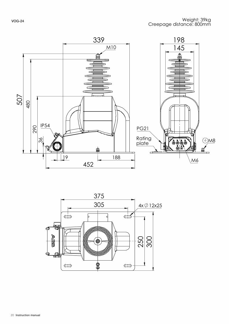
13. Dimensional Drawings
TDO 6

18 Instruction manual
512
30
340
30
67
325
486
Ratingplate
M10
IP54 50
412
PG21M12x30
M6
300 175
180
332
230
4x 14
Weight: 57kgCreepage distance: 1250mm
TJO 6

Instruction manual 19
55
33 450
170
680
637
3
75
M12
IP54Ratingplate
5
R125
115
PG21M6
M8
310
190
220
340
4x 12
Weight: 52-55kgCreepage distance: 1120mm
55
33 450
170
680
637
3
75
M12
IP54Ratingplate
5
R125
115
PG21M6
M8
310
190
220
340
4x 12
Weight: 52-55kgCreepage distance: 1120mm
TJO 7
20 Instruction manual
36
19
339
188
290
4
80
507
452
M10
IP54
145198
Rating plate
PG21
M8
M6
375
250
300
305 4x 12x25
Weight: 39kgCreepage distance: 800mm
VOG-24

Instruction manual 21
18
36
188
336
450
M10
IP54
415342
475
M6
M8
PG21Rating plate
375
250
300
305
4x 12x25
Weight: 43kgCreepage distance: 800mm
VOL-24

22 Instruction manual
VOL-40.52RFA016266 - version with baseplate

Instruction manual 23
VOL-40.52RFA016267 - version with rails

34
08
PL
13
07
-W1
-en
Ed
itio
n 0
7.2
01
5For more information please contact:
ABB Contact CenterPhone: +48 22 22 37 777e-mail: [email protected]
ABB Sp. z o.o.Branch Office in Przasnyszul. Leszno 5906-300 PrzasnyszPhone: +48 22 22 38 900Fax: +48 22 22 38 950
www.abb.pl
We reserve the right to make technical changes or modify the contents of this document without prior notice. With regard to purchase orders, the terms and conditions agreed shall apply. ABB Sp. z o.o. does not accept any responsibility whatsoever for potential errors or possible lack of information in this document.
We reserve all rights to this document and the subject matter and illustrations contained herein. Any reproduction, disclosure to third parties or utilisation of its contents — in whole or in parts — is forbidden without prior written consent of ABB Sp. z o.o.
© Copyright 2015 ABBAll rights reserved