oundation fieldbus interface software (for the … a6268 part number d301653x012 november 2009...
TRANSCRIPT

Form A6268 Part Number D301653X012 November 2009
FOUNDATION™ Fieldbus Interface Software (for the ROC800-Series) User Manual
Remote Automation Solutions

FOUNDATION Fieldbus Interface Software User Manual
ii Issued Nov-09
Revision Tracking Sheet
November 2009
This manual may be revised periodically to incorporate new or updated information. The revision date of each page appears at the bottom of the page opposite the page number. A change in revision date to any page also changes the date of the manual that appears on the front cover. Listed below is the revision date of each page (if applicable):
Page Revision Initial issue Nov-09
NOTICE Remote Automation Solutions (“RAS”), division of Emerson Process Management shall not be liable for technical or editorial errors in this manual or omissions from this manual. RAS MAKES NO WARRANTIES, EXPRESSED OR IMPLIED, INCLUDING THE IMPLIED WARRANTIES OF MERCHANTABILITY AND FITNESS FOR A PARTICULAR PURPOSE WITH RESPECT TO THIS MANUAL AND, IN NO EVENT SHALL RAS BE LIABLE FOR ANY INCIDENTAL, PUNITIVE, SPECIAL OR CONSEQUENTIAL DAMAGES INCLUDING, BUT NOT LIMITED TO, LOSS OF PRODUCTION, LOSS OF PROFITS, LOSS OF REVENUE OR USE AND COSTS INCURRED INCLUDING WITHOUT LIMITATION FOR CAPITAL, FUEL AND POWER, AND CLAIMS OF THIRD PARTIES.
Bristol, Inc., Bristol Canada, BBI SA de CV and Emerson Process Management Ltd., Remote Automation Solutions division (UK) are wholly owned subsidiaries of Emerson Electric Co. doing business as Remote Automation Solutions (“RAS”), a division of Emerson Process Management. ROC, FloBoss, ROCLINK, Bristol, Bristol Babcock, ControlWave, TeleFlow and Helicoid are trademarks of RAS. AMS, PlantWeb and the PlantWeb logo are marks of Emerson Electric Co. The Emerson logo is a trademark and service mark of the Emerson Electric Co. All other trademarks are property of their respective owners.
The contents of this publication are presented for informational purposes only. While every effort has been made to ensure informational accuracy, they are not to be construed as warranties or guarantees, express or implied, regarding the products or services described herein or their use or applicability. RAS reserves the right to modify or improve the designs or specifications of such products at any time without notice. All sales are governed by RAS’ terms and conditions which are available upon request.
RAS does not assume responsibility for the selection, use or maintenance of any product. Responsibility for proper selection, use and maintenance of any RAS product remains solely with the purchaser and end-user.
© 2009 Remote Automation Solutions, division of Emerson Process Management. All rights reserved.

FOUNDATION Fieldbus Interface Software User Manual
Issued Nov-09 1
Chapter 1 – Introduction
This document serves as the user manual for the FOUNDATION™ Fieldbus Interface software. This software is intended for use in the Series 2 ROC800-Series Remote Operations Controllers (ROC800s), and is designed for use in coordination with the Field Interface Configurator software and FOUNDATION Fieldbus Interface hardware, as described in the following manuals:
Field Interface Configurator User Manual (Form A6250). FOUNDATION™ Fieldbus Interface Instruction Manual (Form A6259).
This manual describes how to download, install, and configure the Foundation Fieldbus (“FFbus”) Application software on your ROC800 using ROCLINK™ 800 Configuration Software loaded on a personal computer (PC) running Windows® XP® (with Service Pack 2), or Windows Vista®.
Note: This FFbus Interface software application program is a required software component of the FFbus Interface environment. After you install and configure the ROC800-based software application, you must then also install the Field Interface Configurator software on your PC. The Field Interface Configurator software enables you to configure the FOUNDATION Fieldbus Interface.
1.1 Scope and Organization The sections in this manual are arranged to provide information in the order in which it is needed for first-time users. Once you become familiar with the procedures and the software running in the ROC, you can use the manual as a reference tool.
The manual has the following major sections:
Section 1, Introduction Section 2, Installation Section 3, Configuration Section 4, Reference Materials
This manual assumes that you are familiar with the ROC800 units and their configuration. For more information, refer to the following manuals:
ROC809 Remote Operations Controller Instruction Manual (Form A6116).
ROC827 Remote Operations Controller Instruction Manual (Form A6175).
ROCLINK 800 Configuration Software User Manual (Form A6121).
1.2 Product Overview The FFbus Interface software consists of a program that enables the ROC800 to read and write data to the FFbus Interface. The program provides 100 logicals (iterations), each of which can accommodate one of

FOUNDATION Fieldbus Interface Software User Manual
2 Issued Nov-09
three data types (float, signed, or unsigned integer) and the data’s status. You use an application-specific FOUNDATION Fieldbus screen to define the type of data for each logical.
1.3 Program Requirements The FFbus Application Software version 1.00 is compatible with ROC800 firmware version 3.05 (or greater) and with version 1.85 (or greater) of ROCLINK 800 software.
Program specifics include:
File Name Target Unit/
Version User Defined Point (UDP)
Flash Used(in bytes)
SRAM Used (in bytes)
DRAM Used (in bytes)
ROCLINK 800
Version Display Number
FF.tar ROC800 3.05 196 35,840 5,600 180,224 1.85 196
Note: Connect a PC running ROCLINK 800 to the ROC800’s LOI port before starting the download.
For information on viewing the memory allocation of user programs, refer to Section 7.7 of the ROCLINK 800 Configuration Software User Manual (Form A6121).

FOUNDATION Fieldbus Interface Software User Manual
Chapter 2 – Installation
This section provides instructions for installing the user program into the ROC800. Read Section 1.3 of the manual for program requirements.
Note: Connect a PC running ROCLINK 800 to the Local Operator Interface (LOI) port before you begin the download.
2.1 Downloading the FFbus (FF.tar) Application Program
This section provides instructions for installing the FF.tar program file into the Flash memory on the ROC800.
To download the program using ROCLINK 800 software:
1. Connect the ROC to your computer using the LOI port.
2. Start and logon to ROCLINK 800.
3. Select Utilities > User Program Administrator from the ROCLINK menu bar. The User Program Administrator screen displays (see Figure 1):
Figure 1. User Program Administrator
4. Select any empty program number (in this case, number 1) into which to download the program.
5. Click Browse in the Download User Program File frame. The Select User Program File screen displays (see Figure 2).
6. Select the path and user program file to download from the CD-ROM. (Program files are typically located in the Program Files folder on the
Issued Nov-09 3

FOUNDATION Fieldbus Interface Software User Manual
CD-ROM.) As Figure 2 shows, the screen lists all valid user program files with the .TAR extension:
Figure 2. Select User Program File
7. Click Open to select the program file. The User Program Administrator screen displays. As shown in Figure 3, note that the Download User Program File frame identifies the selected program and that the Download & Start button is active:
Figure 3. User Program Administrator
8. Click Download & Start to begin loading the selected program. The following message displays:
4 Issued Nov-09

FOUNDATION Fieldbus Interface Software User Manual
Figure 4. Confirm Download
9. Click Yes to begin the download. When the download completes the following message displays:
Figure 5. ROCLINK 800 Download Confirmation
10. Click OK. The User Program Administrator screen displays (see Figure 6). Note that:
The Device User Program Environment frame reflects the use of system memory.
The User Programs Installed in Device frame identifies the installed program.
The Status field indicates that the program is loaded and running.
Figure 6. User Program Administrator
11. Proceed to Section 3, Configuration.
Issued Nov-09 5

FOUNDATION Fieldbus Interface Software User Manual
6 Issued Nov-09
[This page is intentionally left blank.]

FOUNDATION Fieldbus Interface Software User Manual
Chapter 3 – Configuration
After you have downloaded and started the FOUNDATION Fieldbus Application program, you use an application-specific FOUNDATION Fieldbus screen (see Figure 7) to configure the program. The application provides 100 point numbers for this screen.
3.1 FOUNDATION Fieldbus Screen
Use this screen to define the values and default values for the three data types (float, unsigned integer, and signed integer) as well as status and fault value configuration.
To access this screen:
1. From the Directory Tree, double-click User Program.
2. Double-click Program #1, FF.
3. Double-click Display #196, Foundation Fieldbus.
4. Double-click #1 No Tag. The Foundation Fieldbus screen displays.
Figure 7. Foundation Fieldbus
5. Review the values in the following fields: Field Description Point Number Selects one of 100 possible points for incoming
fieldbus data.
Issued Nov-09 7

FOUNDATION Fieldbus Interface Software User Manual
8 Issued Nov-09
Field Description Tag Sets an identifying label up to 20 characters long for
the selected point number (fieldbus device). The FF Interface module provides this label when powered.
Float Value Contains the floating value for this point as received from the FFbus Interface.
Note: f you enable the Use Fault Values option and specify a Fault Timeout value, once that timeout period expires the program overwrites this value with the specified Float Fault Value.
Float Fault Value Indicates the value the program uses in the Float Value field if the FFbus Interface does not update that value within the Fault Timeout period.
Unsigned Value Contains the unsigned integer value for this point as received from the FFbus Interface.
If you enable the Use Fault Values option and specify a Fault Timeout value, once that timeout period expires the program overwrites this value with the specified Unsigned Fault Value.
Unsigned Fault Value
Indicates the value the program uses in the Unsigned Value field if the FFbus Interface does not update that value within the Fault Timeout period.
Signed Value Contains the signed integer value for this point as received from the FFbus Interface.
Note: If you enable the Use Fault Values option and specify a Fault Timeout value, once that timeout period expires the program overwrites this value with the specified Signed Fault Value.
Signed Fault Value Indicates the value the program uses in the Signed Value field if the FFbus Interface does not update that value within the Fault Timeout period.
Value TLP Indicates a TLP the ROC800-based Interface uses for mapping. Click … to display a Select TLP screen you use to select the TLP.
Device Value Status
This read-only field shows the status associated with the FFbus data value. In a FFbus device, each data value has an assigned value. The device manufacturer defines the meaning of the value status.
Update Period This read-only field shows, in milliseconds, how much time has passed since the FFbus Interface last updated the selected logical.
Connection Status This read-only field shows the connection status between this data parameter and the FFbus Interface. Valid values are Bad (connection is lost) and Good (connection is present).
Use Fault Values Select to allow the program to use fault values in the event of communication timeouts between the ROC and the FFbus Interface.

FOUNDATION Fieldbus Interface Software User Manual
Field Description Fault Timeout Indicates, in seconds, how long the enabled system
waits before applying the fault values to the particular data types. The default is 5 seconds.
Update Type Indicates whether the update is a scheduled or unscheduled communication.
Direction Indicates whether the data is read from or written to the ROC.
6. Click Apply to save any changes you have made to this screen.
7. Click OK to close the screen. Proceed to Section 3.2 to save the configuration.
3.2 Saving the Configuration
Whenever you modify or change the configuration, it is a good practice to save the final configuration to memory. To save the configuration:
1. Select ROC > Flags. The Flags screen displays:
Figure 8. Flags screen
2. Click Save Configuration. A verification message displays:
Figure 9. Perform screen
Issued Nov-09 9

FOUNDATION Fieldbus Interface Software User Manual
10 Issued Nov-09
3. Click Yes to begin the save process. The Flash Write Status field on the Flags screen displays In Progress. When the process ends, the Flash Write Status field on the Flags screen displays Completed.
4. Click Update on the Flags screen. This completes the process of saving your new configuration.
Note: For archive purposes, you should also save this configuration to your PC’s hard drive or a removable media (such as a diskette or a flash drive) using the File > Save Configuration option on the ROCLINK 800 menu bar.

FOUNDATION Fieldbus Interface Software User Manual
Issued Nov-09 11
Chapter 4 – Reference Materials
This section provides information on the user-defined point type (196) the FOUNDATION Fieldbus program uses.
FOUNDATION Fieldbus Interface Software User Manual
12 Issued Nov-09
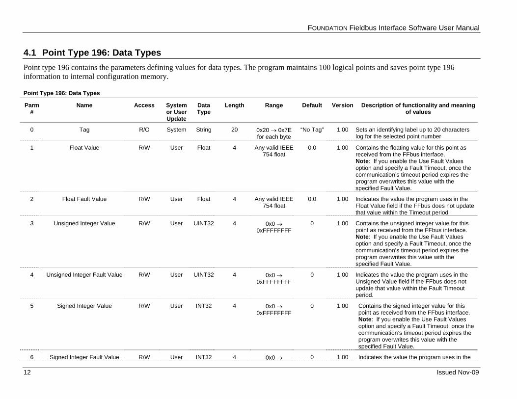
4.1 Point Type 196: Data Types Point type 196 contains the parameters defining values for data types. The program maintains 100 logical points and saves point type 196 information to internal configuration memory.
Point Type 196: Data Types
Parm #
Name Access System or User Update
Data Type
Length Range Default Version Description of functionality and meaning of values
0 Tag R/O System String 20 0x20 → 0x7E for each byte
“No Tag” 1.00 Sets an identifying label up to 20 characters log for the selected point number
1 Float Value R/W User Float 4 Any valid IEEE 754 float
0.0 1.00 Contains the floating value for this point as received from the FFbus interface. Note: If you enable the Use Fault Values option and specify a Fault Timeout, once the communication’s timeout period expires the program overwrites this value with the specified Fault Value.
2 Float Fault Value R/W User Float 4 Any valid IEEE 754 float
0.0 1.00 Indicates the value the program uses in the Float Value field if the FFbus does not update that value within the Timeout period
3 Unsigned Integer Value R/W User UINT32 4 0x0 → 0xFFFFFFFF
0 1.00 Contains the unsigned integer value for this point as received from the FFbus interface. Note: If you enable the Use Fault Values option and specify a Fault Timeout, once the communication’s timeout period expires the program overwrites this value with the specified Fault Value.
4 Unsigned Integer Fault Value R/W User UINT32 4 0x0 → 0xFFFFFFFF
0 1.00 Indicates the value the program uses in the Unsigned Value field if the FFbus does not update that value within the Fault Timeout period.
5 Signed Integer Value R/W User INT32 4 0x0 → 0xFFFFFFFF
0 1.00 Contains the signed integer value for this point as received from the FFbus interface. Note: If you enable the Use Fault Values option and specify a Fault Timeout, once the communication’s timeout period expires the program overwrites this value with the specified Fault Value.
6 Signed Integer Fault Value R/W User INT32 4 0x0 → 0 1.00 Indicates the value the program uses in the
FOUNDATION Fieldbus Interface Software User Manual
Issued Nov-09 13
Point Type 196: Data Types
Parm #
Name Access System or User Update
Data Type
Length Range Default Version Description of functionality and meaning of values
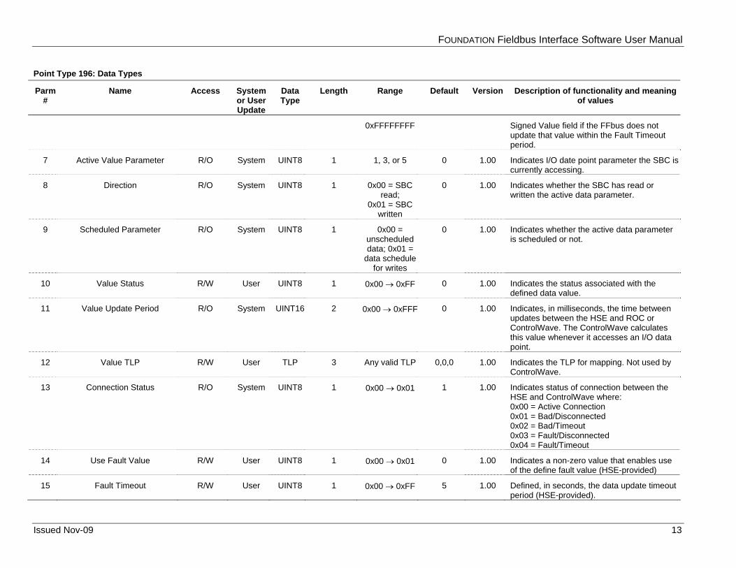
0xFFFFFFFF Signed Value field if the FFbus does not update that value within the Fault Timeout period.
7 Active Value Parameter R/O System UINT8 1 1, 3, or 5 0 1.00 Indicates I/O date point parameter the SBC is currently accessing.
8 Direction R/O System UINT8 1 0x00 = SBC read;
0x01 = SBC written
0 1.00 Indicates whether the SBC has read or written the active data parameter.
9 Scheduled Parameter R/O System UINT8 1 0x00 = unscheduled data; 0x01 =
data schedule for writes
0 1.00 Indicates whether the active data parameter is scheduled or not.
10 Value Status R/W User UINT8 1 0x00 → 0xFF 0 1.00 Indicates the status associated with the defined data value.
11 Value Update Period R/O System UINT16 2 0x00 → 0xFFF 0 1.00 Indicates, in milliseconds, the time between updates between the HSE and ROC or ControlWave. The ControlWave calculates this value whenever it accesses an I/O data point.
12 Value TLP R/W User TLP 3 Any valid TLP 0,0,0 1.00 Indicates the TLP for mapping. Not used by ControlWave.
13 Connection Status R/O System UINT8 1 0x00 → 0x01 1 1.00 Indicates status of connection between the HSE and ControlWave where: 0x00 = Active Connection 0x01 = Bad/Disconnected 0x02 = Bad/Timeout 0x03 = Fault/Disconnected 0x04 = Fault/Timeout
14 Use Fault Value R/W User UINT8 1 0x00 → 0x01 0 1.00 Indicates a non-zero value that enables use of the define fault value (HSE-provided)
15 Fault Timeout R/W User UINT8 1 0x00 → 0xFF 5 1.00 Defined, in seconds, the data update timeout period (HSE-provided).

FOUNDATION Fieldbus Interface Software User Manual
If you have comments or questions regarding this manual, please direct them to your local sales representative or contact:
Remote Automation Solutions Marshalltown, Iowa 50158 USA Houston, TX 77065 USA Pickering, North Yorkshire UK Y018 7JA Website: www.EmersonProcess.com/Remote
14 Issued Nov-09