as-interface fieldbus solutions - lumberg automation usa · reliable actuator sensor interface...
TRANSCRIPT

AS-Interface Fieldbus Solutions
Fieldbus Communication for Actuator Sensor Interface Applications

Lumberg Automation™ Provides Reliable Actuator Sensor Interface Fieldbus Solutions for Industrial Automation Applications Worldwide.

www.lumberg-automationusa.com 1-717-217-2299
Be Certain with Belden
3
Belden® Industrial Solutions — More Convenience and Solutions for Networksin Harsh Environments and Large-scale Infrastructures
Belden Industrial Solutions
For mission-critical applications, Belden is the signal transmission partner that delivers confidence in signal availability, integrity and performance because only Belden can offer solutions that satisfy any requirement.
A majority of system failures occur within the signal transmission space, and trouble-shooting can be very difficult and time-consuming. We want everyone to “Be Certain” that when choosing Belden you receive Signal Availability — always there, Signal Integrity — always trusted and secure, and Signal Performance — always when and where you need it.
Belden has brought together a comprehensive line of industrial cabling, connectivity and networking devices, offering the most reliable communications solutions for your application. Whether you are networking your devices to the controllers, connecting the controllers to the control room, relaying data between the control room, the engineering department, and remote manufacturing sites — or all of the above — Belden has the products you need to seamlessly connect your communications.
From the petrochemical, automotive, pharmaceutical, power generation, pulp and paper, metals, food and beverage, or general manufacturing plant to the corporate headquarters — and everywhere in between — Belden has your signal transmission solution. Belden offers the most dependable network and communications system performance in tough and mission-critical environments.
Our Synergy EnsuresContinuous Performance
With the Hirschmann™ and Lumberg Automation™ product line additions to the Belden offering, our line of Complete Industrial Solutions is uniquely positioned to provide the best network and communications infrastructure possible. Belden products and systems expertise means that you can maintain ongoing operations without interruption and costly downtime — in any environment.
Here are a few more good reasons why Belden is your best choice for industrial networking, communications and control:
• We have the expertise to integrate your industrial and commercial networks.
• Our products are engineered to perform in tough and difficult environments.
• We offer the broadest selection of products, for a complete, end-to-end Ethernet solution.
• Our sales and engineering professionals can audit, recommend/design, configure and assemble the products and systems to your specific requirements.
• Our global manufacturing and distribution network make our products available to you globally.
Offering ComprehensiveService & Support
Belden recognizes that comprehensive know-how is necessary to ensure an optimized, homogenous solution. We also know that consultation, support and training requires more than just a general understanding of the products, technologies and market trends. It requires a solid understanding of the application and the ability to provide the type of support that is needed — when and where it is needed. It requires the four key service and support areas that are critical to success:
• Network Design
• Training
• Technical Support
• System Performance
Network Design
Belden eliminates your design challenges because we understand the issues surrounding the design and operation of networks in industrial and mission-critical environments. Our engineers are available to work with you to deliver high-availability networks that meet your enterprise-wide IT needs. Whether it’s designing systems for Greenfield facilities, or integrating into existing industrial IT environments, our highly-trained staff lifts the design burden from your shoulders to ours.
We’ll consult with you to develop a strategy — or we’ll develop and implement your full design — either way our staff is available to you.
Training
Backed by years of meeting and exceedingthe needs of a broad range of end-userapplications, Belden is ideally suited to offerbeginners and networking experts alike theopportunity to expand their understanding ofmission-critical industrial networks.Belden has developed a series of trainingprograms that are given by Belden-certifiedindividuals — all experts in industrialnetworking and cabling.
Technical Support
At Belden, our personnel are poised to assist our customers — ensuring maximum uptime and reliability. And with offices in North America, Asia and Europe, Belden can respond globally.
System Performance
If Belden designs it, we guarantee performance — period. We are committed to ensuring world-class signal connectivity and to significantly improve your operational up-time. All Belden components are “designed” to deliver optimum performance: from connectors, to cable, to routers and switches. Based on this comprehensive product portfolio, we have the necessary industrial solutions DNA to deliver reliability.
For more information on our service and support offering, including our warranties, please go to the Belden web site at www.belden.com/industrial to locate a Belden sales representative near you.
AS-Interface

4 1-717-217-2299 www.lumberg-automationusa.com
The Lumberg Automation™ Brand Sets the Standard for Quality, Reliability and Service.
About Our Solutions
Today, more than ever, manufacturing productivity depends upon seamless data communication and automation systems. Lumberg Automation has assembled one of the most diversified portfolios for industrial connectivity and distributed I/O systems for control applications.
With the advancements in technology and improved machine designs, industrial controls, such as sensors, actuators, safety light curtains, pushbutton switches and the like are moving closer to the application.
Our Enclosure~less™ Concept
The Enclosure~less concept from Lumberg Automation addresses these applications with an entire suite of industrial hardened connectivity and distributed I/O products.
Enhanced environmental characteristics, modular designs, plug-and-play electronics with quick-disconnect designs are all integrated to increase speed of installation, decrease troubleshooting and maintenance while reducing the overall complexity of the control application. These products provide the optimal solution in machine and equipment design and offer excellent opportunities and benefits to OEMs, system integrators, and end users alike.
Easing the Design Process
Our system approach leads to decreased time and money to develop complete integrated connectivity solutions. Using our Enclosure~less concept is one of the most effective ways to dramatically reduce the design time.
Re-Useable Solutions
OEM’s now have access to a set of standard products designed around the concept that everything is pluggable and interchangeable.
Having the flexibility to re-configure or expand an existing system without worrying about customization is made possible with our Enclosure~less concept. Most importantly, our products are re-usable and can be adapted to future designs or merely put back on the shelf for future use.
Improved Installation Time with
Less Mistakes
A recent study by a group of European manufacturers concluded that Enclosure~less assembly costs save as much as 30 percent over conventional installation methods.
These savings are realized through not only the Enclosure~less concept, but by the technology that is being employed. With a modular design approach and plug-and-play electronic features, less time will be spent running down errors or replacing parts from incorrect wiring.
Trouble-Shooting is Simplified
Troubleshooting circuits can be a long process, especially when one is dealing with several hundred termination points.
Many of our products have integrated LED function indicators which provide a visual notification that a circuit is functioning properly.
By using products that have integrated LED functions, mechanics and engineers alike can quickly isolate and resolve the problem.
Testing Made Simple
OEMs can cost-effectively build and pre-test a machine at their facility, disassemble and transport it to an end user’s plant knowing that everything has been tested. This is primarily made possible through the reduction of wiring terminations throughout the system, which makes testing a much simpler and quicker process.
Reliability is Maximized
Enclosure~less™ solutions can minimize wiring errors because wiring is pre-manufactured with quick-disconnect features. With less manual wiring involved, there are fewer points of failure.
Some studies suggest that a large portion of system failures come from installation rather than part failures. The decrease in errors associated with pre-manufactured wiring leads to an increase in the overall reliability of the control system.
In the end, this helps speed installation and commissioning, maintenance, troubleshooting, and ultimately boosts a plant’s production.
Maintenance/Repair Time is Reduced
Maintenance technicians and operators no longer need to access the control panel since much of the maintenance and troubleshooting can be done outside.
With the simplicity of wiring layout and connections, end users can efficiently isolate problems and replace a starter or I/O locally, rather than sorting through a complex panel. The result is significantly easier troubleshooting and shorter Mean-Time-To-Repair (MTTR).
Floor Space at a Premium
Control cabinets can occupy a substantial amount of the production floor. The Enclosure~less™ concept dramatically reduces the need for that real estate, allowing companies to leverage more of their facility.
Industries like semiconductor and pharmaceutical manufacturing have realized the benefits of the On-Machine approach for years, as their clean-room space is at a premium.

5www.lumberg-automationusa.com 1-717-217-2299
Be Certain with Belden
Table of Contents
Table of Contents
About Belden® Industrial Solutions ......................................................................................................3About Our Solutions .............................................................................................................................4AS-Interface Introduction .....................................................................................................................6-7
AS-Interface Fieldbus Solutions 8-94
AS-Interface Input/Output Modules ................................................................................................... 8-41
4 Inputs ................................................................................................................................................ 8-138 Inputs ................................................................................................................................................ 14-154 Outputs .............................................................................................................................................. 16-198 Outputs .............................................................................................................................................. 20-212 Inputs / 2 Outputs .............................................................................................................................. 22-254 Inputs / 3 Outputs .............................................................................................................................. 26-274 Inputs / 4 Outputs .............................................................................................................................. 28-39Passive Modules ................................................................................................................................... 40-41
AS-Interface Junction Branches ........................................................................................................ 42
Accessories .........................................................................................................................................43-47
Part Number Index .............................................................................................................................. 48
AS-Interface

6 1-717-217-2299 www.lumberg-automationusa.com
AS-Interface Introduction
Common Industrial Protocol
AS-i (Actuator Sensor Interface) was designed as a simple system for the quick data exchange of binary signals. Research, spawned by market demands, has made it possible to transmit analog data as well (also see “The new AS-i-specification V2.1”). That data, however, must not be time-critical, since the transmission of an analog value requires several data cycles
The biggest advantage of AS-i is the quick and uncomplicated installation of the system. Communication (Manchester Encoding) and power supply are transmitted via a 2-wire cable. By using piercing technology for contacting the cable it is possible to insert a new slave at any point in the system. In addition, the arbitrary structure of the bus (line, tree, star, ...) permits the perfect adaptation to the relevant plant or machine.
AS-i is mainly used for small machines, as a subsystem for more complex bus systems (e.g. PROFIBUS-DP) or as an easy introduction to bus technology.
AS-Interface is an open standard. Thus, it is possible to operate different bus participants made by different manufacturers in one network.
About Lumberg Automation AS-i Products
Lumberg Automation remains true to the AS-i easy installation concept and offers compact, solid module technology to the customer. The IP67 components have been designed to use directly on machines.
The flat cable shown below is commonly used with AS-i. However, for some applications such as C-tracks, Lumberg provides connections for round cable for all modules as well.
Technical Data
Transmission media: Unshielded 2-wire cable for power supply (module electronics and sensors) and data transmission (Manchester Encoding and optionally mechanically encoded flat or round cable.
Network Topology
The bus can be built arbitrarily (line, star, tree, ...). Terminating resistors are not required.
Bus Access
• Monomaster system• Master-slave access
Number of Slaves
• 31 slaves by using standard slaves• 62 slaves by using A/B slaves with profile 2.1
Standard Transmission Rates and Segment Lengths
• Transmission rate: 167 kbaud
• Max. segment length: 100 m Bus cycle time
• Standard slaves max. 5 ms in case of full arrangement (31 slaves)
• Just A or B slave per address max. 5 ms in case of full arrangement (31 slaves)
• A and B slave per address max. 10 ms in case of full arrangement (62 slaves)
AS-i Module dipicted with flat cabel and M12 field attachable connectors and junctions.
AS-Interface Modules with Plug-N-Play Connectivity Reduce Overall Installation and Maintenance Costs.

7www.lumberg-automationusa.com 1-717-217-2299
Be Certain with Belden
AS-Interface
Addressing
AS-i slaves are generally addressed via software (the default address is generally “0” for all AS-i slaves). This can be done in several ways:
• Via the master: The slaves are connected to the master consecutively. The latter automatically identifies the kind of slave and starts communicating. Then the slave can be addressed.
• Via an addressing unit: All AS-i slaves can be addressed with the standard addressing unit “0913 ATL 003” (the Lumberg flat cable modules require the adapter “0913 ATL 002 / 0.35M”; modules according to profile 2.1 require the adapter“ 0913 ATL 004 / 1 M).
• Automatic addressing: If a slave in a network fails, AS-i offers the option of auto-addressing. The defective slave is replaced by an identical one. The master identifies this slave and automatically addresses it to the address of the missing slave.
Diagnostic system
According to the AS-i specification 2.1 periphery
errors like short circuit or overload can be sent to
the master in the form of a collective diagnostic.
In addition, there is a status LED on the relevant
slave.
The New AS-i Specification Version 2.1
With the introduced AS-i specification V. 2.1
some innovations have been integrated into the
AS-i system. The most important alteration is the
possibility to operate 62 (instead of 31) slaves
in one network. This became possible by the
introduction of a differentiation between A and B
slaves (e.g. 1A + 1B). To achieve that, the system
had to be designed with one output per slave less
(max. 4I/3O).
The new specification is downward compatible,
and old AS-i slaves can be operated in one
network together with new ones. In addition
to that, the processing of analog values was
improved. The transmission of analog values are
integrated in the master. This means that specific
function blocks need not be used any more.
Transmission Rate AS-i Specification
Version 2.0
AS-i Specification
Version 2.1
Slave Standard A/B Slave
Max. Number of Slaves 31 64
Max. Number of Inputs 4 Inputs x 31 slaves = 124 Inputs 4 Inputs x 62 slaves = 248 Inputs
Max. Number of Outputs 4 Outputs x 31 slaves = 124 Outputs 3 Outputs x 62 slaves = 186 Outputs(one output is needed for the A/B addressing)
Cycle Time 5ms for 31 slaves 10ms for 62 slaves
Analog Value Processing via functional blocks integrated in the master
Table 1: Admissable transmission rates
Integrated AS-i application.
Product Characteristics
Especially suitable for robotic applications (resistance to torsion).
Very good resistance to oils, coolants and lubricants as well as emulsions.
Suitable for use in C-Tracks.
Very good resistance to flying weld slag (e.g.) unfinished constructions).
Very good resistance to acids, lye and chemical cleaning agents.
Very good electromagnetic resistance (EMC) and shieldedsystems.
Very good vibration and shock resistance.
UL approved.
UL/CSA approved.
8 1-717-217-2299 www.lumberg-automationusa.com
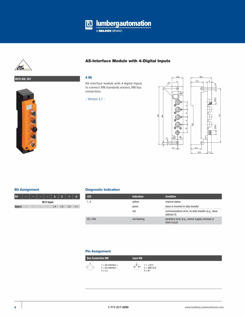
AS-Interface Module with 4-Digital Inputs
0910 ASL 501 4 IN
AS-interface module with 4 digital inputs to connect M8 standards sensors, M8 bus connection.
– Version 2.1 -
Pin Assignment
Bus Connection M8 Input M8
1 = AS-interface +2 = AS-interface -4 = n.c.
1 = +24 V2 = GND (0 V)4 = IN
Diagnostic Indication
LED Indication Condition
1..4 yellow channel status
green slave is involved in data transfer
red communications error, no data transfer (e.g., slave address 0)
AS-i-DIA red flashing periphery error (e.g., sensor supply overload or short circuit
Bit Assignment
Bit - - - - 3 2 1 0
M12 Input
Byte 0 - - - - I-4 I-3 I-2 I-1

9www.lumberg-automationusa.com 1-717-217-2299
Be Certain with Belden
AS-Interface Module with 4-Digital Inputs0910 ASL 501
Part Number
0910 ASL 501
The application of these products in harsh environments should always be checked before use. Specifications subject to alteration.
Technical Data
Environmental
Degree of protection IP 67Operating temperature range -15°C (+5°F) to +60°C (+140°F)Weight 100 gHousing material PUR
Bus system AS-Interface Version 2.1
AS-Interface profile S 0.A.EI/O configuration 0 hexID code A hexID2 code (extended ID-code) E hexSupport A/B addressing yes
Electronics power supply AS-Interface
Rated voltage AS-Interface netVoltage range 26.5–31.6 V DCPower consumption max. 120 mAReverse polarity protection yesIndication LED green
Inputs Type 2 acc. to IEC 61131-2
Rated input voltage 24 V DCSignal state “1” Us > 11 V / Is > 6 mASignal state “0” Is < 2 mAInput current at 24 V 15 mAInput circuit p-switchingNumber of digital channels 4Channel status indicator LED yellow per channel
Diagnostic
Indication LED red
Connection via cordset, double-ended
M8 / M8 e.g. RSMV-RKMV (please see product group cordsets, double-ended)
Included in delivery / Accessories
Dust covers M8 2 piecesAttachable label 1 piece
AS-Interface

10 1-717-217-2299 www.lumberg-automationusa.com
AS-Interface Module with 4-Digital Inputs
0910 ASL 409 4 IN
AS-Interface flat cable module with 4 digital inputs to connect standard sensors, combined M12 socket, infrared interface for the addressing.
– Version 2.1 -
Diagnostic Indication
LED Indication Condition
I-1..4 yellow channel status
U-AS-i green AS-Interface power supply active
FIDred communication error
red flashing periphery error 9sensor/actuator short circuit
Bit Assignment
Bit - - - - 3 2 1 0
M12 Input
Byte 0 - - - - I-4 I-3/4 I-2 I-1/2
Pin Assignments
Input 1 M12 Input 2 M12 Input 3 M12 Input 4 M12
1 = +24 V2 = IN 23 = GND (0 V)4 = IN 15 = earth
1 = +24 V2 = n.c.3 = GND (0 V)4 = IN 25 = earth
1 = +24 V2 = IN 43 = GND (0 V)4 = IN 35 = earth
1 = +24 V2 = n.c.3 = GND (0 V)4 = IN 35 = earth
The connection to earth for the inputs is implemented via the earthing contacts at the fastening holes.

11www.lumberg-automationusa.com 1-717-217-2299
Be Certain with Belden
AS-Interface Module with 4-Digital Inputs0910 ASL 409
Part Number
0910 ASL 409
The application of these products in harsh environments should always be checked before use. Specifications subject to alteration.
Technical Data
Environmental
Degree of protection IP 67Operating temperature range -25°C (-13°F) to +80°C (+176°F)Weight 200 gHousing material PUR
Bus system AS-Interface Version 2.1
AS-Interface profile S 0.A.EI/O configuration 0 hexID code A hexID2 code (extended ID-code) E hexSupport A/B addressing yes
Electronics power supply AS-Interface
Rated voltage AS-Interface netVoltage range 26.5–31.6 V DCPower consumption max. 250 mAReverse polarity protection yesIndication LED green
Input power supply
Voltage range (AS-Interface net) 17–30 VTotal current of all sensors max. 200 mAShort circuit-proof yes
Inputs Type 2 acc. to IEC 61131-2
Rated input voltage 24 V DCSignal state “1” Us > 11 V / Is > 6 mASignal state “0” Is < 2 mAInput current at 15 mAInput circuit p-switchingNumber of digital channels 4Channel status indicator LED yellow per channel
Diagnostic
Indication LED red
Included in delivery / Accessories
Dust covers M12 2 piecesAttachable label 10 pieces
Note
The input channels are connected together. That allows a greater connection flexibility (see pin assignment). In case of connection of a two-channel sensor to input socket 1 or 3 a further sensor must not be plugged to input socket 2 or 4 respectively due to the Y wiring of the inputs.
AS-Interface
12 1-717-217-2299 www.lumberg-automationusa.com
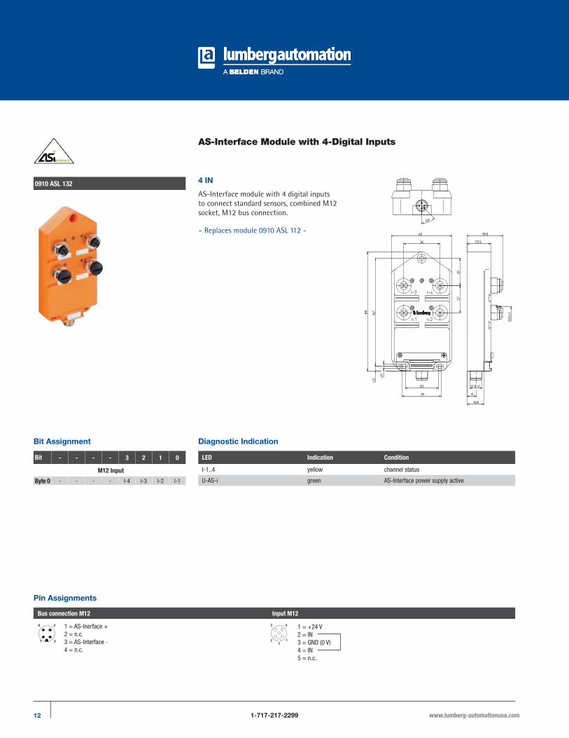
AS-Interface Module with 4-Digital Inputs
0910 ASL 132 4 IN
AS-Interface module with 4 digital inputs to connect standard sensors, combined M12 socket, M12 bus connection.
– Replaces module 0910 ASL 112 -
Diagnostic Indication
LED Indication Condition
I-1..4 yellow channel status
U-AS-i green AS-Interface power supply active
Bit Assignment
Bit - - - - 3 2 1 0
M12 Input
Byte 0 - - - - I-4 I-3 I-2 I-1
Pin Assignments
Bus connection M12 Input M12
1 = AS-Inerface +2 = n.c.3 = AS-Interface -4 = n.c.
1 = +24 V2 = IN3 = GND (0 V)4 = IN5 = n.c.

13www.lumberg-automationusa.com 1-717-217-2299
Be Certain with Belden
AS-Interface Module with 4-Digital Inputs0910 ASL 132
Part Number
0910 ASL 132
The application of these products in harsh environments should always be checked before use. Specifications subject to alteration.
Technical Data
Environmental
Degree of protection IP 67Operating temperature range -25°C (-13°F) to +80°C (+176°F)Weight 200 gHousing material PUR
Bus system AS-Interface Version 2.1
AS-Interface profile S 0.A.EI/O configuration 0 hexID code 0 hexID2 code (extended ID-code) F hexSupport A/B addressing yes
Electronics power supply AS-Interface
Rated voltage AS-Interface netVoltage range 26.5–31.6 V DCPower consumption max. 250 mAReverse polarity protection yesIndication LED green
Input power supply
Voltage range (AS-Interface net) 17–30 VTotal current of all sensors max. 200 mAShort circuit-proof yes
Inputs Type 2 acc. to IEC 61131-2
Rated input voltage 24 V DCSignal state “1” Us > 11 V / Is > 6 mASignal state “0” Is < 2 mAInput current at 15 mAInput circuit p-switchingNumber of digital channels 4Channel status indicator LED yellow per channel
Diagnostic
Indication LED red
Connection via cordset, double-ended
M12 / M12 0915 034 101/... M
Included in delivery / Accessories
Dust covers M12 2 piecesAttachable label 10 pieces
AS-Interface

14 1-717-217-2299 www.lumberg-automationusa.com
AS-Interface Module with 8-Digital Inputs
0910 ASL 412 8 IN
AS-Interface flat cable modulewith 8 digital inputs to connect standard sensors, combined M12 socket, infrared interface for the addressing.
– Version 2.1 -
Diagnostic Indication
LED Indication Condition
I-1..4 yellow channel status
U-AS-i green AS-Interface power supply active
FIDred communication error
red flashing periphery errot (sensor/actuator short circuit
Bit Assignment
Bit - - - - 3 2 1 0
M12 Input
Byte 0 / Slave 1 - - - - I-4 I-3 I-2 I-1Byte 1 / Slave 2 I-4 I-3 I-2 I-1
Pin Assignments
Input 1 M12 Input 2 M12 Input 3 M12 Input 4 M12
1 = +24 V2 = IN 23 = GND (0 V)4 = IN 15 = earth
1 = +24 V2 = n.c.3 = GND (0 V)4 = IN 25 = earth
1 = +24 V2 = IN 43 = GND (0 V)4 = IN 35 = earth
1 = +24 V2 = n.c.3 = GND (0 V)4 = IN 45 = earth
The connection to earth for the inputs is implemented via the earthing contacts at the fastening holes.

15www.lumberg-automationusa.com 1-717-217-2299
Be Certain with Belden
AS-Interface Module with 8-Digital Inputs0910 ASL 412
Part Number
0910 ASL 412
The application of these products in harsh environments should always be checked before use. Specifications subject to alteration.
Technical Data
Environmental
Degree of protection IP 67Operating temperature range -25°C (-13°F) to +80°C (+176°F)Weight 300 gHousing material PUR
Bus system AS-Interface Version 2.1
AS-Interface profile S 0.A.EI/O configuration 0 hexID code 1 hexID2 code (extended ID-code) E hexSupport A/B addressing yes
Electronics power supply AS-Interface
Rated voltage AS-Interface netVoltage range 26.5–31.6 V DCPower consumption max. 500 mAReverse polarity protection yesIndication LED green
Input power supply
Voltage range (AS-Interface net) 17–30 VTotal current of all sensors max. 200 mAShort circuit-proof yes
Inputs Type 2 acc. to IEC 61131-2
Rated input voltage 24 V DCSignal state “1” Us > 11 V / Is > 6 mASignal state “0” Is < 2 mAInput circuit p-switchingNumber of digital channels 8Channel status indicator LED yellow per channel
Diagnostic
Indication LED red
Included in delivery / Accessories
Dust covers M12 2 piecesAttachable label 10 pieces
Note
The input channels are connected together. That allows a greater connection flexibility (see pin assignment). In case of connection of a two-channel sensor to input socket 1 or 3 a further sensor must not be plugged to input socket 2 or 4 respectively due to the Y wiring of the inputs.
AS-Interface

16 1-717-217-2299 www.lumberg-automationusa.com
AS-Interface Module with 4-Digital Outputs
0910 ASL 403 4 OUT
AS-Interface flat cable module with 4 digital outputs to connect standard actuators, combined M12 socket.
Diagnostic Indication
LED Indication Condition
O-1..4 yellow channel status
U-AS-i green AS-Interface power supply active
AUX green actuator supply active
Bit Assignment
Bit - - - - 3 2 1 0
M12 Output
Byte 0 - - - - O-4 O-3 O-2 O-1
Pin Assignments
Output M12
1 = n.c.2 = n.c.3 = GND (0 V)4 = OUT5 = earth

17www.lumberg-automationusa.com 1-717-217-2299
Be Certain with Belden
AS-Interface Module with 4-Digital Outputs0910 ASL 403
Part Number
0910 ASL 403
The application of these products in harsh environments should always be checked before use. Specifications subject to alteration.
Technical Data
Environmental
Degree of protection IP 67Operating temperature range -25°C (-13°F) to +80°C (+176°F)Weight 200 gHousing material PUR
Bus system AS-Interface
AS-Interface profile 8.0I/O configuration 8 hexID code 0 hexSupport A/B addressing no
Electronics power supply AS-Interface
Rated voltage AS-Interface netVoltage range 26.5–31.6 V DCPower consumption max. 75 mAReverse polarity protection yesIndication LED green
Output power supply AUX
Rated voltage 24 V DCVoltage range 10–30 VPotential separation presentReverse polarity protection yes/electronicIndication LED green
Outputs Type 2 A acc. to IEC 61131-21-2
Rated output current 2 A per channelShort circuit-proof yesMax. output current 4 A per moduleOverload-proof yesNumber of digital channels 4Channel type N.O. p-switchingChannel status indicator LED yellow per channel
Included in delivery / Accessories
Dust covers M12 2 piecesAttachable label 10 pieces
AS-Interface

18 1-717-217-2299 www.lumberg-automationusa.com
AS-Interface Module with 4-Digital Outputs
0910 ASL 133 4 OUT
AS-Interface module with 4 digital outputs to connect standard actuators, combined M12 socket, M12 bus connection.
– Replaces module 0910 ASL 111 -
Diagnostic Indication
LED Indication Condition
O-1..4 yellow channel status
U-AS-i green AS-Interface power supply active
AUX green actuator supply active
Bit Assignment
Bit - - - - 3 2 1 0
M12 Output
Byte 0 - - - - O-4 O-3 O-2 O-1
Pin Assignments
Bus connection M12 Output M12
1 = AS-Inerface +2 = 0 V AUX3 = AS-Interface -4 = +24 V AUX
1 = n.c.2 = n.c.3 = GND (0 V)4 = OUT5 = earth

19www.lumberg-automationusa.com 1-717-217-2299
Be Certain with Belden
AS-Interface Module with 4-Digital Outputs0910 ASL 133
Part Number
0910 ASL 133
The application of these products in harsh environments should always be checked before use. Specifications subject to alteration.
Technical Data
Environmental
Degree of protection IP 67Operating temperature range -25°C (-13°F) to +80°C (+176°F)Weight 200 gHousing material PUR
Bus system AS-Interface
AS-Interface profile S 8.0.FI/O configuration 8 hexID code 0 hexID2 code (extended ID-code) F hexSupport A/B addressing no
Electronics power supply AS-Interface
Rated voltage AS-Interface netVoltage range 26.5–31.6 V DCPower consumption max. 75 mAReverse polarity protection yesIndication LED green
Output power supply AUX
Rated voltage 24 V DCVoltage range 10–30 VPotential separation presentReverse polarity protection yes/electronicIndication LED green
Outputs Type 2 A acc. to IEC 61131-21-2
Rated output current 2 A per channelShort circuit-proof yesMax. output current 4 A per moduleOverload-proof yesNumber of digital channels 4Channel type N.O. p-switchingChannel status indicator LED yellow per channel
Connection via cordset, double-ended
M12 / M12 0915 034 101/... M
Included in delivery / Accessories
Dust covers M12 2 piecesAttachable label 10 pieces
AS-Interface
20 1-717-217-2299 www.lumberg-automationusa.com
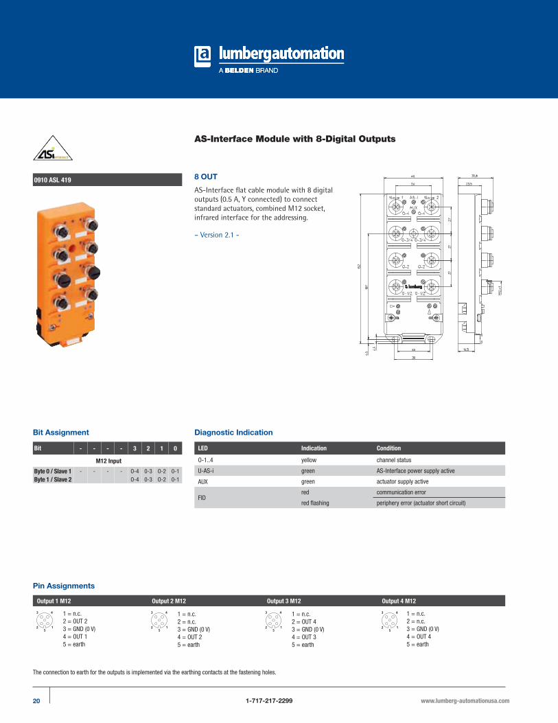
AS-Interface Module with 8-Digital Outputs
0910 ASL 419 8 OUT
AS-Interface flat cable module with 8 digital outputs (0.5 A, Y connected) to connect standard actuators, combined M12 socket, infrared interface for the addressing.
– Version 2.1 -
Diagnostic Indication
LED Indication Condition
O-1..4 yellow channel status
U-AS-i green AS-Interface power supply active
AUX green actuator supply active
FIDred communication error
red flashing periphery error (actuator short circuit)
Bit Assignment
Bit - - - - 3 2 1 0
M12 Input
Byte 0 / Slave 1 - - - - O-4 0-3 O-2 0-1Byte 1 / Slave 2 O-4 0-3 O-2 0-1
Pin Assignments
Output 1 M12 Output 2 M12 Output 3 M12 Output 4 M12
1 = n.c.2 = OUT 23 = GND (0 V)4 = OUT 15 = earth
1 = n.c.2 = n.c.3 = GND (0 V)4 = OUT 25 = earth
1 = n.c.2 = OUT 43 = GND (0 V)4 = OUT 35 = earth
1 = n.c.2 = n.c.3 = GND (0 V)4 = OUT 45 = earth
The connection to earth for the outputs is implemented via the earthing contacts at the fastening holes.
21www.lumberg-automationusa.com 1-717-217-2299
Be Certain with Belden
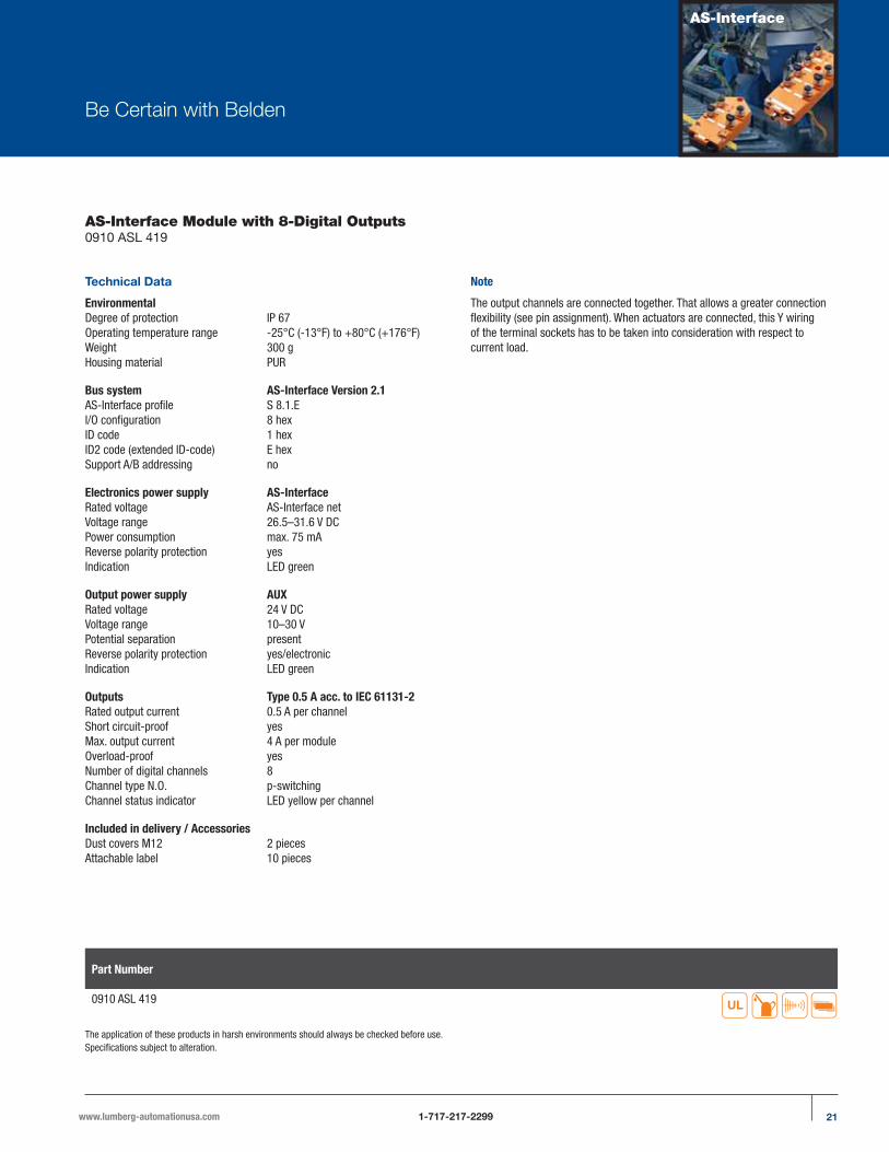
AS-Interface Module with 8-Digital Outputs0910 ASL 419
Part Number
0910 ASL 419
The application of these products in harsh environments should always be checked before use. Specifications subject to alteration.
Technical Data
Environmental
Degree of protection IP 67Operating temperature range -25°C (-13°F) to +80°C (+176°F)Weight 300 gHousing material PUR
Bus system AS-Interface Version 2.1
AS-Interface profile S 8.1.EI/O configuration 8 hexID code 1 hexID2 code (extended ID-code) E hexSupport A/B addressing no
Electronics power supply AS-Interface
Rated voltage AS-Interface netVoltage range 26.5–31.6 V DCPower consumption max. 75 mAReverse polarity protection yesIndication LED green
Output power supply AUX
Rated voltage 24 V DCVoltage range 10–30 VPotential separation presentReverse polarity protection yes/electronicIndication LED green
Outputs Type 0.5 A acc. to IEC 61131-2
Rated output current 0.5 A per channelShort circuit-proof yesMax. output current 4 A per moduleOverload-proof yesNumber of digital channels 8Channel type N.O. p-switchingChannel status indicator LED yellow per channel
Included in delivery / Accessories
Dust covers M12 2 piecesAttachable label 10 pieces
Note
The output channels are connected together. That allows a greater connection flexibility (see pin assignment). When actuators are connected, this Y wiring of the terminal sockets has to be taken into consideration with respect to current load.
AS-Interface
22 1-717-217-2299 www.lumberg-automationusa.com
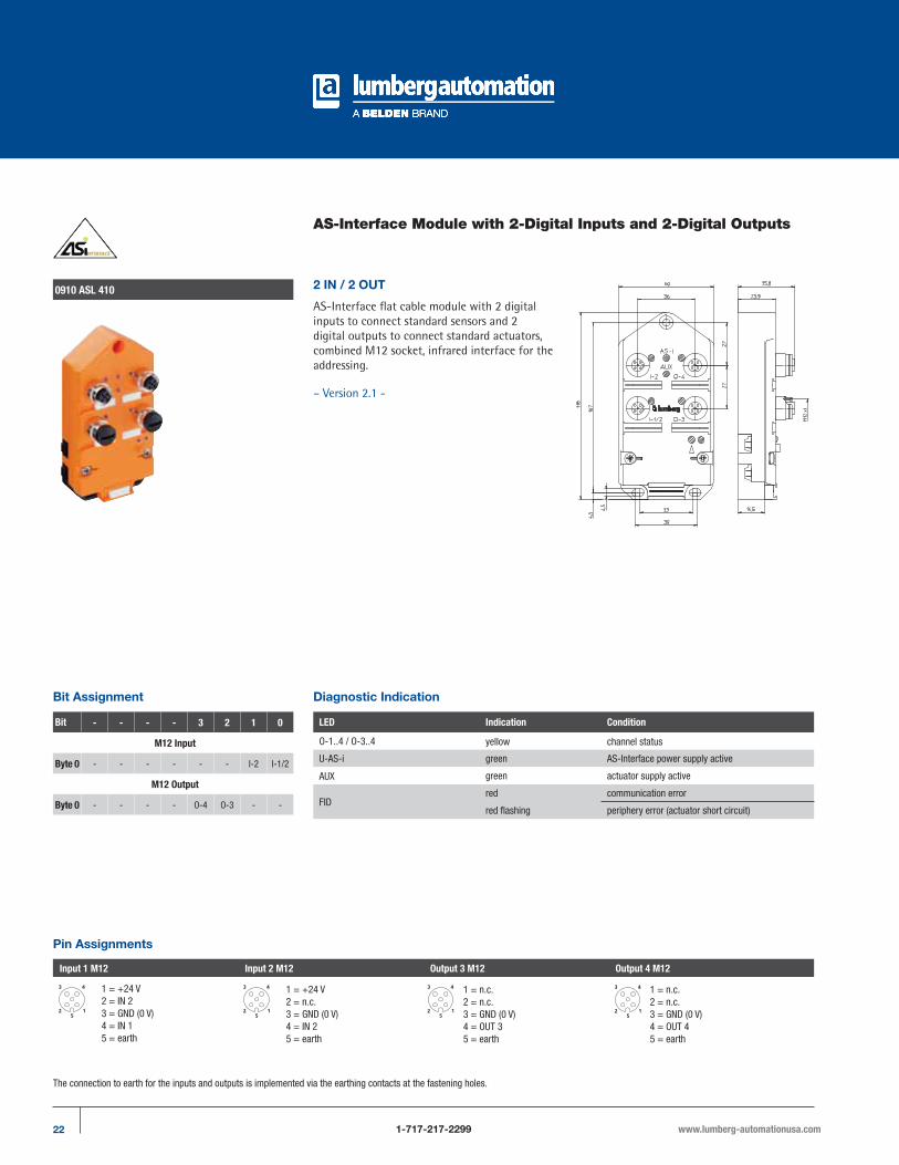
AS-Interface Module with 2-Digital Inputs and 2-Digital Outputs
0910 ASL 410 2 IN / 2 OUT
AS-Interface flat cable module with 2 digital inputs to connect standard sensors and 2 digital outputs to connect standard actuators, combined M12 socket, infrared interface for the addressing.
– Version 2.1 -
Diagnostic Indication
LED Indication Condition
O-1..4 / O-3..4 yellow channel status
U-AS-i green AS-Interface power supply active
AUX green actuator supply active
FIDred communication error
red flashing periphery error (actuator short circuit)
Bit Assignment
Pin Assignments
Input 1 M12 Input 2 M12 Output 3 M12 Output 4 M12
1 = n.c.2 = n.c.3 = GND (0 V)4 = OUT 35 = earth
1 = n.c.2 = n.c.3 = GND (0 V)4 = OUT 45 = earth
The connection to earth for the inputs and outputs is implemented via the earthing contacts at the fastening holes.
Bit - - - - 3 2 1 0
M12 Input
Byte 0 - - - - - - I-2 I-1/2
M12 Output
Byte 0 - - - - O-4 O-3 - -
1 = +24 V2 = IN 23 = GND (0 V)4 = IN 15 = earth
1 = +24 V2 = n.c.3 = GND (0 V)4 = IN 25 = earth

23www.lumberg-automationusa.com 1-717-217-2299
Be Certain with Belden
AS-Interface Module with 2-Digital Inputs and 2-Digital Outputs0910 ASL 410
Part Number
0910 ASL 410
The application of these products in harsh environments should always be checked before use. Specifications subject to alteration.
Technical Data
Environmental
Degree of protection IP 67Operating temperature range -25°C (-13°F) to +80°C (+176°F)Weight 200 gHousing material PUR
Bus system AS-Interface Version 2.1
AS-Interface profile S 3.F.EI/O configuration 3 hexID code F hexID2 code (extended ID-code) E hexSupport A/B addressing no
Electronics power supply AS-Interface
Rated voltage AS-Interface netVoltage range 26.5–31.6 V DCPower consumption max. 250 mAReverse polarity protection yesIndication LED green
Input power supply
Voltage range (AS-Interface net) 17–30 VTotal current of all sensors max. 200 mAShort circuit-proof yes
Inputs Type 2 acc. to IEC 61131-2
Rated input voltage 24 V DCSignal state “1” Us > 11 V / Is > 6 mASignal state “0” Is < 2 mAInput current at 24 V 15 mAInput circuit p-switchingNumber of digital channels 2Channel status indicator LED yellow per channel
Output power supply AUX
Rated voltage 24 V DCVoltage range 10–30 VPotential separation presentReverse polarity protection yes/electronicIndication LED green
Outputs Type 2 A acc. to IEC 61131-2
Rated output current 2 A per channelShort circuit-proof yesMax. output current 4 A per moduleOverload-proof yesNumber of digital channels 2Channel type N.O. p-switchingChannel status indicator LED yellow per channel
Diagnostic
Indication LED red
Included in delivery / Accessories
Dust covers M12 2 piecesAttachable label 10 pieces
Note
The input channels are connected together. That allows a greater connection flexibility (see pin assignment). In case of connection of a two-channel sensor to input socket 1 a further sensor must not be plugged to input socket 2 respectively due to the Y wiring of the inputs.
AS-Interface

24 1-717-217-2299 www.lumberg-automationusa.com
AS-Interface Module with 2-Digital Inputs and 2-Digital Outputs
0910 ASL 134 2 IN / 2 OUT
AS-Interface module with 2 digital inputs to connect standard sensors and 2 digital outputs to connect standard actuators, combined M12 socket, M12 bus connection.
– Replaces module 0910 ASL 110 -
Diagnostic Indication
LED Indication Condition
O-1..4 / O-3..4 yellow channel status
U-AS-i green AS-Interface power supply active
AUX green actuator supply active
Bit Assignment
Pin Assignments
1 = n.c.2 = n.c.3 = GND (0 V)4 = OUT5 = earth
Bit - - - - 3 2 1 0
M12 Input
Byte 0 - - - - - - I-2 I-1/2
M12 Output
Byte 0 - - - - O-4 O-3 - -
Pin Assignments
Bus connection M12 Input M12 Output M12
1 = AS-Inerface +2 = 0 V AUX3 = AS-Interface -4 = +24 V AUX
1 = +24 V2 = IN3 = GND (0 V)4 = IN5 = n.c.

25www.lumberg-automationusa.com 1-717-217-2299
Be Certain with Belden
AS-Interface Module with 2-Digital Inputs and 2-Digital Outputs0910 ASL 134
Part Number
0910 ASL 134
The application of these products in harsh environments should always be checked before use. Specifications subject to alteration.
Technical Data
Environmental
Degree of protection IP 67Operating temperature range -25°C (-13°F) to +80°C (+176°F)Weight 200 gHousing material PUR
Bus system AS-Interface Version 2.1
AS-Interface profile S 3.F.EI/O configuration 3 hexID code 0 hexID2 code (extended ID-code) F hexSupport A/B addressing no
Electronics power supply AS-Interface
Rated voltage AS-Interface netVoltage range 26.5–31.6 V DCPower consumption max. 250 mAReverse polarity protection yesIndication LED green
Input power supply
Voltage range (AS-Interface net) 17–30 VTotal current of all sensors max. 200 mAShort circuit-proof yes
Inputs Type 2 acc. to IEC 61131-2
Rated input voltage 24 V DCSignal state “1” Us > 11 V / Is > 6 mASignal state “0” Is < 2 mAInput current at 24 V 15 mAInput circuit p-switchingNumber of digital channels 2Channel status indicator LED yellow per channel
Output power supply AUX
Rated voltage 24 V DCVoltage range 10–30 VPotential separation presentReverse polarity protection yes/electronicIndication LED green
Outputs Type 2 A acc. to IEC 61131-2
Rated output current 2 A per channelShort circuit-proof yesMax. output current 4 A per moduleOverload-proof yesNumber of digital channels 2Channel type N.O. p-switchingChannel status indicator LED yellow per channel
Diagnostic
Indication LED red
Connection via cordset, double-ended
M12 / M12 0915 034 101/... M
Included in delivery / Accessories
Dust covers M12 2 piecesAttachable label 10 pieces
AS-Interface

26 1-717-217-2299 www.lumberg-automationusa.com
AS-Interface Module with 4-Digital Inputs and 3-Digital Outputs
0910 ASL 414 4 IN / 3 OUT
AS-Interface module with 2 digital inputs to connect standard sensors and 2 digital outputs to connect standard actuators, combined M12 socket, M12 bus connection.
– Version 2.1 -
Diagnostic Indication
LED Indication Condition
O-1..4 / O-3..4 yellow channel status
AS-i green AS-Interface power supply active
AUX green actuator supply active
FID
red communication error
red flashing periphery error (actuator short circuit/sensor supply error)
Bit Assignment
Bit - - - - 3 2 1 0
M12 Input
Byte 0 - - - - I-4 I-3/4 I-2 I-1/2
M12 Output
Byte 0 - - - - - O-3 O-2 O-1
Pin Assignments
Input 1 M12 Input 2 M12 Input 3 M12 Input 4 M12
Output 1 M12 Output 2 M12 Output 3 M12
1 = +24 V2 = IN 23 = GND (0 V)4 = IN 15 = earth
1 = +24 V2 = n.c.3 = GND (0 V)4 = IN 25 = earth
1 = n.c.2 = n.c.3 = GND (0 V)4 = OUT 15 = earth
1 = n.c.2 = n.c.3 = GND (0 V)4 = OUT 25 = earth
1 = n.c.2 = n.c.3 = GND (0 V)4 = OUT 35 = earth
1 = +24 V2 = IN 43 = GND (0 V)4 = IN 35 = earth
1 = +24 V2 = n.c.3 = GND (0 V)4 = IN 45 = earth
The connection to earth for the outputs is implemented via the earthing contacts at the fastening holes.

27www.lumberg-automationusa.com 1-717-217-2299
Be Certain with Belden
AS-Interface Module with 4-Digital Inputs and 3-Digital Outputs0910 ASL 414
Part Number
0910 ASL 414
The application of these products in harsh environments should always be checked before use. Specifications subject to alteration.
Technical Data
Environmental
Degree of protection IP 67Operating temperature range -25°C (-13°F) to +80°C (+176°F)Weight 300 gHousing material PUR
Bus system AS-Interface Version 2.1
AS-Interface profile S 7.A.EI/O configuration 7 hexID code A hexID2 code (extended ID-code) E hexSupport A/B addressing yes
Electronics power supply AS-Interface
Rated voltage AS-Interface netVoltage range 26.5–31.6 V DCPower consumption max. 100 mAReverse polarity protection yesIndication LED green
Input power supply
Voltage range (AS-Interface net) 17–30 VTotal current of all sensors max. 100 mAShort circuit-proof yes
Inputs Type 2 acc. to IEC 61131-2
Rated input voltage 24 V DCSignal state “1” Us > 10 V / Is > 4.7 mASignal state “0” Is < 1.5 mAInput current at 24 V 15 mAInput circuit p-switchingNumber of digital channels 4Channel status indicator LED yellow per channel
Output power supply AUX
Rated voltage 24 V DCVoltage range 10–30 VPotential separation presentReverse polarity protection yes/electronicIndication LED green
Outputs Type 2 A acc. to IEC 61131-2
Rated output current 2 A per channelShort circuit-proof yesMax. output current 4 A per moduleOverload-proof yesNumber of digital channels 3Channel type N.O. p-switchingChannel status indicator LED yellow per channel
Diagnostic
Indication LED red
Included in delivery / Accessories
Dust covers M12 2 piecesAttachable label 10 pieces
Note
The input channels are connected together. That allows a greater connection flexibility (see pin assignment). In case of connection of a two-channel sensor to input socket 1 or 3 a further sensor must not be plugged to input socket 2 or 4 respectively due to the Y wiring of the inputs.
AS-Interface

28 1-717-217-2299 www.lumberg-automationusa.com
AS-Interface Module with 4-Digital Inputs and 4-Digital Outputs
0910 ASL 408 4 IN / 4 OUT
AS-Interface flat cable module with 4 digital inputs to connect standard sensors and 4 digital outputs to connect standard actuators, combined M12 socket, infrared interface for the addressing.
– Version 2.1 -
Diagnostic Indication
LED Indication Condition
O-1..4 / O-3..4 yellow channel status
AS-i green AS-Interface power supply active
AUX green actuator supply active
FIDred communication error
red flashing periphery error (actuator short circuit)
Bit Assignment
Bit - - - - 3 2 1 0
M12 Input
Byte 0 - - - - I-4 I-3/4 I-2 I-1/2
M12 Output
Byte 0 - - - - O-4 O-3 O-2 O-1
Pin Assignments
Input 1 M12 Input 2 M12 Input 3 M12 Input 4 M12
Output 1 M12 Output 2 M12 Output 3 M12 Output M12
1 = +24 V2 = IN 23 = GND (0 V)4 = IN 15 = earth
1 = +24 V2 = n.c.3 = GND (0 V)4 = IN 25 = earth
1 = n.c.2 = n.c.3 = GND (0 V)4 = OUT 15 = earth
1 = n.c.2 = n.c.3 = GND (0 V)4 = OUT 25 = earth
1 = n.c.2 = n.c.3 = GND (0 V)4 = OUT 35 = earth
1 = n.c.2 = n.c.3 = GND (0 V)4 = OUT 45 = earth
1 = +24 V2 = IN 43 = GND (0 V)4 = IN 35 = earth
1 = +24 V2 = n.c.3 = GND (0 V)4 = IN 45 = earth
The connection to earth for the inputs and outputs is implemented via the earthing contacts at the fastening holes.
29www.lumberg-automationusa.com 1-717-217-2299
Be Certain with Belden
AS-Interface Module with 4-Digital Inputs and 4-Digital Outputs0910 ASL 408
Part Number
0910 ASL 408
The application of these products in harsh environments should always be checked before use. Specifications subject to alteration.
Technical Data
Environmental
Degree of protection IP 67Operating temperature range -25°C (-13°F) to +80°C (+176°F)Weight 300 gHousing material PUR
Bus system AS-Interface Version 2.1
AS-Interface profile S 7.A.EI/O configuration 7 hexID code F hexID2 code (extended ID-code) E hexSupport A/B addressing yes
Electronics power supply AS-Interface
Rated voltage AS-Interface netVoltage range 26.5–31.6 V DCPower consumption max. 250 mAReverse polarity protection yesIndication LED green
Input power supply
Voltage range (AS-Interface net) 17–30 VTotal current of all sensors max. 200 mAShort circuit-proof yes
Inputs Type 2 acc. to IEC 61131-2
Rated input voltage 24 V DCSignal state “1” Us > 11 V / Is > 6 mASignal state “0” Is < 2 mAInput current at 24 V 15 mAInput circuit p-switchingNumber of digital channels 4Channel status indicator LED yellow per channel
Output power supply AUX
Rated voltage 24 V DCVoltage range 10–30 VPotential separation presentReverse polarity protection yes/electronicIndication LED green
Outputs Type 2 A acc. to IEC 61131-2
Rated output current 2 A per channelShort circuit-proof yesMax. output current 4 A per moduleOverload-proof yesNumber of digital channels 4Channel type N.O. p-switchingChannel status indicator LED yellow per channel
Diagnostic
Indication LED red
Included in delivery / Accessories
Dust covers M12 2 piecesAttachable label 10 pieces
Note
The input channels are connected together. That allows a greater connection flexibility (see pin assignment). In case of connection of a two-channel sensor to input socket 1 or 3 a further sensor must not be plugged to input socket 2 or 4 respectively due to the Y wiring of the inputs.
AS-Interface

30 1-717-217-2299 www.lumberg-automationusa.com
AS-Interface Module with 4-Digital Inputs and 4-Digital Outputs
0910 ASL 135 4 IN / 4 OUT
AS-Interface module with 4 digital inputs to connect standard sensors and 4 digital outputs to connect standard actuators, combined M12 socket, M12 bus connection.
– Replaces module 0910 ASL 109 -
Diagnostic Indication
LED Indication Condition
O-1..4 / O-4..4 yellow channel status
U-AS-i green AS-Interface power supply active
AUX green actuator supply active
Bit Assignment
Bit - - - - 3 2 1 0
M12 Input
Byte 0 - - - - I-4 I-3 I-2 I-1
M12 Output
Byte 0 - - - - O-4 O-3 O-2 O-1
Pin Assignments
1 = n.c.2 = n.c.3 = GND (0 V)4 = OUT5 = earth
Pin Assignments
Bus connection M12 Input M12 Output M12
1 = AS-Inerface +2 = 0 V AUX3 = AS-Interface -4 = +24 V AUX
1 = +24 V2 = IN3 = GND (0 V)4 = IN5 = n.c.

31www.lumberg-automationusa.com 1-717-217-2299
Be Certain with Belden
AS-Interface Module with 4-Digital Inputs and 4-Digital Outputs0910 ASL 135
Part Number
0910 ASL 135
The application of these products in harsh environments should always be checked before use. Specifications subject to alteration.
Technical Data
Environmental
Degree of protection IP 67Operating temperature range -25°C (-13°F) to +80°C (+176°F)Weight 200 gHousing material PUR
Bus system AS-Interface Version 2.1
AS-Interface profile S 7.A.EI/O configuration 7 hexID code 0 hexID2 code (extended ID-code) F hexSupport A/B addressing yes
Electronics power supply AS-Interface
Rated voltage AS-Interface netVoltage range 26.5–31.6 V DCPower consumption max. 250 mAReverse polarity protection yesIndication LED green
Input power supply
Voltage range (AS-Interface net) 17–30 VTotal current of all sensors max. 200 mAShort circuit-proof yes
Inputs Type 2 acc. to IEC 61131-2
Rated input voltage 24 V DCSignal state “1” Us > 11 V / Is > 6 mASignal state “0” Is < 2 mAInput current at 24 V 15 mAInput circuit p-switchingNumber of digital channels 4Channel status indicator LED yellow per channel
Output power supply AUX
Rated voltage 24 V DCVoltage range 10–30 VPotential separation presentReverse polarity protection yes/electronicIndication LED green
Outputs Type 2 A acc. to IEC 61131-2
Rated output current 2 A per channelShort circuit-proof yesMax. output current 4 A per moduleOverload-proof yesNumber of digital channels 4Channel type N.O. p-switchingChannel status indicator LED yellow per channel
Diagnostic
Indication LED red
Connection via cordset, double-ended
M12 / M12 0915 034 101/... M
Included in delivery / Accessories
Dust covers M12 2 piecesAttachable label 10 pieces
AS-Interface

32 1-717-217-2299 www.lumberg-automationusa.com
AS-Interface Module with 4-Digital Inputs and 4-Digital Outputs
0910 ASL 424 4 IN / 4 OUT
AS-Interface module with housing and receptacle shells in stainless steel, 4 digital inputs (Y connected) to connect standard sensors and 4 digital outputs (2 A, Y connected)to connect standard actuators, M12 bus connection.
– especially designed for food and beverage equipment -
Diagnostic Indication
LED Indication Condition
O-1..4 / O-4..4 yellow channel status
AS-i green AS-Interface power supply active
AUX green actuator supply active
DIA
red communication error
red flashing periphery error (actuator short circuit/sensor supply error)
Bit Assignment
Bit - - - - 3 2 1 0
M12 Input
Byte 0 - - - - I-4 I-3/4 I-2 I-1/2
M12 Output
Byte 0 - - - - O-4 O-3/4 O-2 O-1/2
Pin Assignments
Bus connection M12 Input 1 M12 Input 2 M12 Input 3 M12 Input 4 M12
Output 1 M12 Output 2 M12 Output 3 M12 Output 4 M12
1 = +24 V2 = IN 23 = GND (0 V)4 = IN 15 = earth
1 = n.c.2 = OUT 23 = GND (0 V)4 = OUT 15 = earth
1 = +24 V2 = n.c.3 = GND (0 V)4 = IN 25 = earth
1 = n.c.2 = n.c.3 = GND (0 V)4 = OUT 25 = earth
1 = +24 V2 = IN 43 = GND (0 V)4 = IN 35 = earth
1 = n.c.2 = OUT 43 = GND (0 V)4 = OUT 35 = earth
1 = +24 V2 = n.c.3 = GND (0 V)4 = IN 45 = earth
1 = n.c.2 = n.c.3 = GND (0 V)4 = OUT 45 = earth
1 = AS-Interface +2 = 0 V AUX3 = AS-Interface -4 = +24 V AUX5 = earth
The connection to earth for the outputs is implemented via the earthing contacts at the fastening holes.

33www.lumberg-automationusa.com 1-717-217-2299
Be Certain with Belden
AS-Interface Module with 4-Digital Inputs and 4-Digital Outputs0910 ASL 424
Part Number
0910 ASL 424
The application of these products in harsh environments should always be checked before use. Specifications subject to alteration.
Technical Data
Environmental
Degree of protection IP 69KOperating temperature range -25°C (-13°F) to +80°C (+176°F)Weight 550 gHousing material stainless steel
Bus system AS-Interface Version 2.1
AS-Interface profile S 7.A.EI/O configuration 7 hexID code E hexID2 code (extended ID-code) F hexSupport A/B addressing no
Electronics power supply AS-Interface
Rated voltage AS-Interface netVoltage range 26.5–31.6 V DCPower consumption max. 310 mAReverse polarity protection yesIndication LED green
Input power supply
Voltage range (AS-Interface net) 17–30 VTotal current of all sensors max. 200 mAShort circuit-proof yes
Inputs Type 2 acc. to IEC 61131-2
Rated input voltage 24 V DCSignal state “1” Us > 10 V / Is > 4.7 mASignal state “0” Is < 1.5 mAInput current at 24 V 15 mAInput circuit p-switchingNumber of digital channels 4Channel status indicator LED yellow per channel
Output power supply AUX
Rated voltage 24 V DCVoltage range 10–30 VPotential separation presentReverse polarity protection yes/electronicIndication LED green
Outputs Type 2 A acc. to IEC 61131-2
Rated output current 2 A per channelShort circuit-proof yesMax. output current 4 A per moduleOverload-proof yesNumber of digital channels 4Channel type N.O. p-switchingChannel status indicator LED yellow per channel
Diagnostic
Indication LED red
Included in delivery / Accessories
Dust covers M12 4 pieces
Note
The input and output channels are connected together. That allows a greater connection flexibility (see pin assignment). On the input side the special characteristics of the Y wiring with one channel or two-channel sensors has to be taken into consideration. On the output side the current load has to be accounted for.
AS-Interface

34 1-717-217-2299 www.lumberg-automationusa.com
AS-Interface Module with 4-Digital Inputs and 4-Digital Outputs
0910 ASL 425 4 IN / 4 OUT
AS-Interface module with housing and receptacle shells in stainless steel, 4 digital inputs to connect standard sensors and 4 digital outputs (2 A) to connect standard actuators, M12 bus connection.
– especially designed for food and beverage equipment -
Diagnostic Indication
LED Indication Condition
O-1..4 / O-4..4 yellow channel status
AS-i green AS-Interface power supply active
AUX green actuator supply active
DIA
red communication error
red flashing periphery error (actuator short circuit/sensor supply error)
Bit Assignment
Bit - - - - 3 2 1 0
M12 Input
Byte 0 - - - - I-4 I-3 I-2 I-1
M12 Output
Byte 0 - - - - O-4 O-3 O-2 O-1
Pin Assignments
Bus connection M12 Input 1 M12 Input 2 M12 Input 3 M12 Input 4 M12
Output 1 M12 Output 2 M12 Output 3 M12 Output 4 M12
1 = +24 V2 = IN 23 = GND (0 V)4 = IN 15 = earth
1 = n.c.2 = n.c.3 = GND (0 V)4 = OUT 15 = earth
1 = +24 V2 = n.c.3 = GND (0 V)4 = IN 25 = earth
1 = n.c.2 = n.c.3 = GND (0 V)4 = OUT 25 = earth
1 = +24 V2 = n.c.3 = GND (0 V)4 = IN 35 = earth
1 = n.c.2 = n.c.3 = GND (0 V)4 = OUT 35 = earth
1 = +24 V2 = n.c.3 = GND (0 V)4 = IN 45 = earth
1 = n.c.2 = n.c.3 = GND (0 V)4 = OUT 45 = earth
1 = AS-Interface +2 = 0 V AUX3 = AS-Interface -4 = +24 V AUX5 = earth
The connection to earth for the outputs is implemented via the earthing contacts at the fastening holes.

35www.lumberg-automationusa.com 1-717-217-2299
Be Certain with Belden
AS-Interface Module with 4-Digital Inputs and 4-Digital Outputs0910 ASL 425
Part Number
0910 ASL 425
The application of these products in harsh environments should always be checked before use. Specifications subject to alteration.
Technical Data
Environmental
Degree of protection IP 69KOperating temperature range -25°C (-13°F) to +80°C (+176°F)Weight 550 gHousing material stainless steel
Bus system AS-Interface Version 2.1
AS-Interface profile S 7.A.EI/O configuration 7 hexID code E hexID2 code (extended ID-code) F hexSupport A/B addressing no
Electronics power supply AS-Interface
Rated voltage AS-Interface netVoltage range 26.5–31.6 V DCPower consumption max. 250 mAReverse polarity protection yesIndication LED green
Input power supply
Voltage range (AS-Interface net) 17–30 VTotal current of all sensors max. 200 mAShort circuit-proof yes
Inputs Type 2 acc. to IEC 61131-2
Rated input voltage 24 V DCSignal state “1” Us > 10 V / Is > 4.7 mASignal state “0” Is < 1.5 mAInput current at 24 V 15 mAInput circuit p-switchingNumber of digital channels 4Channel status indicator LED yellow per channel
Output power supply AUX
Rated voltage 24 V DCVoltage range 10–30 VPotential separation presentReverse polarity protection yes/electronicIndication LED green
Outputs Type 2 A acc. to IEC 61131-2
Rated output current 2 A per channelShort circuit-proof yesMax. output current 4 A per moduleOverload-proof yesNumber of digital channels 4Channel type N.O. p-switchingChannel status indicator LED yellow per channel
Diagnostic
Indication LED red
Included in delivery / Accessories
Dust covers M12 4 pieces
AS-Interface
36 1-717-217-2299 www.lumberg-automationusa.com
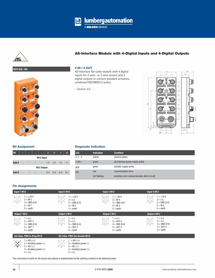
AS-Interface Module with 4-Digital Inputs and 4-Digital Outputs
0910 ASL 146 4 IN / 4 OUTAS-Interface flat cable module with 4 digital
inputs for 2-wire- or 3-wire sensors and 4
digital outputs to connect standard actuators,
combined FIXCON/M12 socket.
– Version 3.0 -
Diagnostic IndicationBit Assignment
Bit - - - - 3 2 1 0
M12 Input
Byte 0 - - - - I-4 I-3 I-2 I-1
M12 Output
Byte 0 - - - - 0-4 O-3 0-2 O-1
LED Indication Condition
O-1...4 yellow channel status
U-AS-i green AS-Interface power supply active
AUX green actuator supply active
DIA red communication error
red flashing periphery error (sensor/actuator short circuit)
Pin Assignments
Input 1 M12 Input 2 M12 Input 3 M12 Input 4 M12
Output 1 M12 Output 2 M12 Output 3 M12 Output 4 M12
AS-i/Aux. PWR In (Plug M12) AS-i/Aux. PWR Out (Socket M12)
1 = +24 V2 = IN 23 = GND (0 V)4 = IN 15 = earth
1 = n.c.2 = OUT 23 = GND (0 V)4 = OUT 15 = earth
1 = AS-i (+)2 = Auxiliary power (-)3 = AS-i (-)4 = Auxiliary power (+)5 = n.c.
1 = +24 V2 = n.c.3 = GND (0 V)4 = IN 25 = earth
1 = n.c.2 = n.c.3 = GND (0 V)4 = OUT 25 = earth
1 = AS-i (+)2 = Auxiliary power (-)3 = AS-i (-)4 = Auxiliary power (+)5 = n.c.
1 = +24 V2 = IN 43 = GND (0 V)4 = IN 35 = earth
1 = n.c.2 = OUT 43 = GND (0 V)4 = OUT 35 = earth
1 = +24 V2 = n.c.3 = GND (0 V)4 = IN 45 = earth
1 = n.c.2 = n.c.3 = GND (0 V)4 = OUT 45 = earth
The connection to earth for the inputs and outputs is implemented via the earthing contacts at the fastening holes.

37www.lumberg-automationusa.com 1-717-217-2299
Be Certain with Belden
AS-Interface Module with 4-Digital Inputs and 4-Digital Outputs0910 ASL 146
Part Number
0910 ASL 146
The application of these products in harsh environments should always be checked before use. Specifications subject to alteration.
Technical Data
Environmental
Degree of protection IP 67Temperature range -25°C / +80°CWeight 300 gHousing PUR
Bus System AS-Interface V3.0
AS-Interface profile S 7.A.7I/O configuration 7 hexID code A hexID2 code (extended ID-code) 7 hexSupport A/B addressing yes
Electronics Power Supply AS-Interface
Rated voltage AS-Interface netVoltage range 26.5–31.6 V DCPower consumption max. 250 mAReverse polarity protection yesIndication LED green
Input Power Supply
Voltage range (AS-Interface net) 17-30 VTotal current of all sensors max. 250 mAShort circuit-proof yes
Inputs Type 2 acc. to IEC 61131-2
Rated input voltage 2 24 V DCSignal state “1” Us>11 V / Is > 6 mASignal state “0” Is < 2 mAInput current at 24 V 15 mAInput circuit p-switchingNumber of digital channels 4Channel status indicator LED yellow per channel
Output Power Supply AUX
Rated voltage 24 V DCVoltage range 10–30 VPotential separation presentReverse polarity protection yes/electronicIndication LED green
Outputs Type 2 A acc. to
IEC 61131-2
Rated output current 2 A per channelShort circuit-proof yesMax. output current 4 A per moduleOverload-proof yesNumber of digital channels 4Channel type N.O. p-switchingChannel status indicator LED yellow per channel
Diagnostic
Indication LED red
Included in delivery / accessories
Dust covers M12 2 piecesAttachable labels 10 pieces
Note
The input- and output channels are connected together. That allows a greater connection flexibility (see pin assignment). In case of connection of a two-chan-nel sensor/actuator to input/output socket 1 or 3 a further sensor/actuator must not be plugged to input/output socket 2 or 4 respectively due to the Y wiring of the inputs/outputs.
*
* = submitted
AS-Interface

38 1-717-217-2299 www.lumberg-automationusa.com
AS-Interface Module with 4-Digital Inputs and 4-Digital Outputs
0910 ASL 438 4 IN / 4 OUTAS-Interface flat cable module with 4 digital
inputs for 2-wire or 3-wire sensors and 4
digital outputs to connect standard actuators,
combined FIXCON/M12 socket, infrared
interface for the addressing.
– Version 3.0 -
Diagnostic IndicationBit Assignment
Bit - - - - 3 2 1 0
M12 Input
Byte 0 - - - - I-4 I-3/4 I-2 I-1/2
M12 Output
Byte 0 - - - - 0-4 O-3/4 0-2 O-1/2
LED Indication Condition
I-1..4/O-1..4 yellow channel status
U-AS-i green AS-Interface power supply active
AUX green actuator supply active
FID red communication error
red flashing periphery error (sensor/actuator short circuit)
Pin Assignments
Input 1 M12 Input 2 M12 Input 3 M12 Input 4 M12
Output 1 M12 Output 2 M12 Output 3 M12 Output 4 M12
1 = +24 V2 = IN 23 = GND (0 V)4 = IN 15 = earth
1 = n.c.2 = OUT 23 = GND (0 V)4 = OUT 15 = earth
1 = +24 V2 = n.c.3 = GND (0 V)4 = IN 25 = earth
1 = n.c.2 = n.c.3 = GND (0 V)4 = OUT 25 = earth
1 = +24 V2 = IN 43 = GND (0 V)4 = IN 35 = earth
1 = n.c.2 = OUT 43 = GND (0 V)4 = OUT 35 = earth
1 = +24 V2 = n.c.3 = GND (0 V)4 = IN 45 = earth
1 = n.c.2 = n.c.3 = GND (0 V)4 = OUT 45 = earth
The connection to earth for the inputs and outputs is implemented via the earthing contacts at the fastening holes.
39www.lumberg-automationusa.com 1-717-217-2299
Be Certain with Belden
AS-Interface Module with 4-Digital Inputs and 4-Digital Outputs0910 ASL 438
Part Number
0910 ASL 438
The application of these products in harsh environments should always be checked before use. Specifications subject to alteration.
Technical Data
Environmental
Degree of protection IP 67Temperature range -25°C / +80°CWeight 300 gHousing PUR
Bus System AS-Interface V3.0
AS-Interface profile S 7.A.7I/O configuration 7 hexID code A hexID2 code (extended ID-code) 7 hexSupport A/B addressing yes
Electronics Power Supply AS-Interface
Rated voltage AS-Interface netVoltage range 26.5–31.6 V DCPower consumption max. 250 mAReverse polarity protection yesIndication LED green
Input Power Supply
Voltage range (AS-Interface net) 17-30 VTotal current of all sensors max. 250 mAShort circuit-proof yes
Inputs Type 2 acc. to IEC 61131-2
Rated input voltage 2 24 V DCSignal state “1” Us>11 V / Is > 6 mASignal state “0” Is < 2 mAInput current at 24 V 15 mAInput circuit p-switchingNumber of digital channels 4Channel status indicator LED yellow per channel
Output Power Supply AUX
Rated voltage 24 V DCVoltage range 10–30 VPotential separation presentReverse polarity protection yes/electronicIndication LED green
Outputs Type 2 A acc. to
IEC 61131-2
Rated output current 2 A per channelShort circuit-proof yesMax. output current 4 A per moduleOverload-proof yesNumber of digital channels 4Channel type N.O. p-switchingChannel status indicator LED yellow per channel
Diagnostic
Indication LED red
Included in delivery / accessories
Dust covers M12 2 piecesAttachable labels 10 pieces
Note
The input- and output channels are connected together. That allows a greater connection flexibility (see pin assignment). In case of connection of a two-chan-nel sensor/actuator to input/output socket 1 or 3 a further sensor/actuator must not be plugged to input/output socket 2 or 4 respectively due to the Y wiring of the inputs/outputs.
*
* = submitted
AS-Interface

40 1-717-217-2299 www.lumberg-automationusa.com
AS-Interface Passive Modules, 4-Ports
0911 ANC 002 4 Ports / On-Board M23
AS-Interface passive module to connect 4 AS-Interface sensors, AS-Interface actuators or ASInterface round cable modules, 4 ports, combined M12 socket with connection for AS-Interface standard round cables and on-board M23 connection for aux power.
Pin Assignments
Bus connection M12 Input 1 M12
1 = AS-Interface +2 = 0 V AUX3 = AS-Interface -4 = +24 V AUX5 = earth
1 = earth2 = +24 V3 = GND (0 V)4 = n.c.5 = n.c.6 = n.c.
0911 ANC 403 4 Ports
AS-Interface passive module to connect 4 AS-Interface sensors, AS-Interface actuators or ASInterface round cable modules, 4 ports, combined M12 socket, with connection for AS-Interface standard flat cables.
*a Standard flat cable
* b Additional power supply
(AS-Interface output levles)

41www.lumberg-automationusa.com 1-717-217-2299
Be Certain with Belden
AS-Interface Passive Modules, 4-Ports0911 ANC 002 / 0911 ANC 403
Part Number Outer Jacket Cable lenghts
0911 ANC 002/...M PUR/PVC 5 M / 10 M
0911 ANC 403
The application of these products in harsh environments should always be checked before use. Specifications subject to alteration.
Technical Data
Environmental
Degree of protection IP 67Operating temperature range -25°C (-13°F) to +80°C (+176°F)Housing material PUR
Cable Specifications 0911 ANC 002:
PUR/PVC - cable-no. 41 Further information please see chapter “Cable specifications”
AS-Interface

42 1-717-217-2299 www.lumberg-automationusa.com
AS-Interface Junction Branches
0911 ANC 101
0911 ANC 401
AS-Interface branch to connect AS-Interface slaves via a M12 connector with a flat cable system.
AS-Interface branch to connect two flat cables (opening of an AS-Interface branch or additional voltage supply).
Part Number
0911 ANC 101
0911 ANC 401
The application of these products in harsh environments should always be checked before use. Specifications subject to alteration.
Technical Data
Environmental
Degree of protection IP 65Housing material PANominal current at 40°C 4 A
Note
– insertion of the AS-Interface flat cable (yellow) in cable shaft “LINE1“
– insertion of the additional voltage supply (black flat cable) in cable shaft “LINE 2“
Technical Data
Environmental
Degree of protection IP 65Housing material PANominal current at 40°C 8 A
Note
Please be aware that only two wires with the same function may be inserted into this AS-Interface branch. This means that either only the yellow or only the black AS-Interface flat cable may be used.
Pin Assignments
Cable M12 - 5 Poles
1 = AS-Interface +2 = 0 V AUX3 = AS-Interface -4 = +24 V AUX5 = earth
1 = AS-Interface + brown2 = 0 V AUX white3 = AS-Interface - blue4 = +24 V AUX black5 = earth green/yellow

43www.lumberg-automationusa.com 1-717-217-2299
Be Certain with Belden
AS-Interface Accessories
0911 ANC 407/... M 0911 ANC 410/... M
AS-Interface connector for direct connection to a wired male connector: reusable access technology to IEC 60352-6. AS-Interface connector. 0911 ANC 406 is included with the delivered product.
AS-Interface connector for direct connection to two wired male connectors: reusable access technology to IEC 60352-6. AS-Interface connector 0911 ANC 406 is included with the delivered product.
Part Number Outer Jacket Standard Cable Lengths
0911 ANC 407/...M PUR/PVC 2 M / 5 M / 10 M
0911 ANC 410/...M PUR/PVC 0.3 M / 0.6 M / 1 M / 2 M / 5 M / 10 M / 15 M
The application of these products in harsh environments should always be checked before use. Specifications subject to alteration.
Technical Data
Environmental
Degree of protection IP 67Housing material PAInsert PURNominal current at 40°C 2 A per contact
Technical Data
Environmental
Degree of protection IP 67Housing material PAInsert PURNominal current at 40°C 2 A per contact
Pin Assignments
2-Poles 2-Poles
1 = brown2 = blue
1 = brown2 = blue
AS-Interface

44 1-717-217-2299 www.lumberg-automationusa.com
AS-Interface Accessories
0911 ANC 408 0911 ANC 4130911 ANC 406
0911 ANC 415
AS-Interface cable connector, used for distribution of connections or as connector: reusable access technology to IEC 60352-6. AS-Interface connector 0911 ANC 406 is included with the delivered product.
AS-Interface cable connector, used for distribution of connections or as connector: reusable access technology to IEC 68 and DIN 41611, hexagon screw in stainless steel, 4 poles. AS-Interface connector 0911 ANC 415 is included with the delivered product.
– especially designed for food and beverage equipment –
AS-Interface connector for AS-Interface cables.
AS-Interface connector for AS-Interface cables.
Part Number
0911 ANC 408 0911 ANC 406
0911 ANC 413 0911 ANC 415
The application of these products in harsh environments should always be checked before use. Specifications subject to alteration.
Technical Data
Degree of protection IP 67Molded body PAInsert PANominal current at 40°C 4 A
Technical Data
Degree of protection IP 67 / IP 69KMolded body PBTInsert PBTNominal current at 40°C 4 A
Technical Data
Molded body PA
Technical Data
Molded body PBT
45www.lumberg-automationusa.com 1-717-217-2299
Be Certain with Belden
AS-Interface Accessories
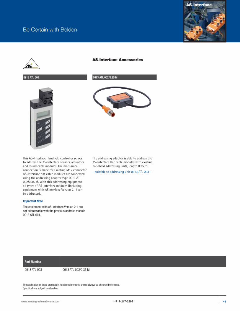
0913 ATL 003 0913 ATL 002/0.35 M
This AS-Interface Handheld controller serves to address the AS-Interface sensors, actuators and round cable modules. The mechanical connection is made by a mating M12 connector.AS-Interface flat cable modules are connected using the addressing adaptor type 0913 ATL 002/0.35 M. With this addressing equipment, all types of AS-Interface modules (including equipment with ASInterface Version 2.1) can be addressed.
Important Note
The equipment with AS-Interface Version 2.1 are not addressable with the previous address module 0913 ATL 001.
The addressing adaptor is able to address the AS-Interface flat cable modules with existing handheld addressing units, length 0.35 m.
– suitable to addressing unit 0913 ATL 003 –
Part Number
0913 ATL 003 0913 ATL 002/0.35 M
The application of these products in harsh environments should always be checked before use. Specifications subject to alteration.
AS-Interface

46 1-717-217-2299 www.lumberg-automationusa.com
AS-Interface Accessories
Part Number Poles Out Jacket Standard Cable Lengths
0915 034 101/...M 4 PUR 1 M / 3 M / 5 M
The application of these products in harsh environments should always be checked before use. Specifications subject to alteration.
0915 034 101/... M
AS-Interface cordset, doubleended, M12 male connector and M12 female connector with self-locking threaded joint.
Technical Data
Environmental
Degree of protection IP 67Temperature range -25°C / +80°C
Materials
Housing / Molded body TPU, self-extinguishingInsert TPU, self-extinguishingContact Male connector: CuZn, prenickeled and 0.8 microns gold-platedFemale connector: CuZn, prenickeled and 0.3 microns gold-platedReceptacle shell / knurled screw/nut / hexagon screw/nut / sleeve CuZn, nickel-platedO-ring FKM (only female connector)
Electrical data
Nominal current at 40°C 4 ANominal voltage 240 VRated voltage 250 VTest voltage 2.0 kV eff. / 60 sInsulation resistance > 109 �Pollution degree 3
Cable specification PUR/PVC - cable-no. 34 Further information please see chapter ”Cable specifications”
Pin Assignments
4-Poles
1 = brown2 = white3 = blue4 = black

47www.lumberg-automationusa.com 1-717-217-2299
Be Certain with Belden
AS-Interface Accessories
0911 ANC 409
Terminal sleeves for flat cable, packing unit: 10 pieces.
Part Number
0913 ANC 409
The application of these products in harsh environments should always be checked before use. Specifications subject to alteration.
AS-Interface
48 1-717-217-2299 www.lumberg-automationusa.com
Part Number Index
Part Number Page No.
0910 ASL 132 12-13
0910 ASL 133 18-19
0910 ASL 134 24-25
0910 ASL 135 30-31
0910 ASL 146 36-37
0910 ASL 403 16-17
0910 ASL 408 28-29
0910 ASL 409 10-11
0910 ASL 410 22-23
0910 ASL 412 14-15
0910 ASL 414 26-27
0910 ASL 419 20-21
0910 ASL 424 32-33
0910 ASL 425 34-35
Part Number Page No.
0910 ASL 438 38-39
0910 ASL 501 8-9
0911 ANC 002/5 M 40-41
0911 ANC 002/10 M 40-41
0911 ANC 101 42
0911 ANC 401 42
0911 ANC 403 40-41
0911 ANC 406 44
0911 ANC 407/2 M 43
0911 ANC 407/5 M 43
0911 ANC 407/10 M 43
0911 ANC 408 44
0911 ANC 410/0.3 M 43
0911 ANC 410/0.5 M 43
Part Number Page No.
0911 ANC 410/1 M 43
0911 ANC 410/2 M 43
0911 ANC 410/5 M 43
0911 ANC 410/10 M 43
0911 ANC 410/15 M 43
0911 ANC 413 44
0911 ANC 415 44
0913 ANC 409 47
0913 ATL 002/0.35 M 45
0913 ATL 003 45
0915 034 101/1 M 46
0915 034 101/3 M 46
0915 034 101/5 M 46

Be Certain with Belden
AS-Interface
Regarding the details in this catalog: Alterations may have been made to the product after the editorial deadline for this publication, namely 03/01/2011. The manufacturer reserves the right to alter the construction and form, manufacture different shades and amend the scope of delivery during the delivery period insofar as the alterations and differences are acceptable to the buyer while allowing for the seller’s interests. Insofar as the seller or the manufacturer uses signs or numbers to mark the order or the ordered item, no rights may be derived from this alone. The illustrations may also contain accessories and special equipment which are not part of the mass-produced scope of delivery. Color differences are attributable to technical aspects of the printing process. This publication may also contain types and support services that are not made available/rendered in some countries. The information/details in this publication merely contain general descriptions or performance factors which, when applied in an actual situation, do not always correspond with the described form and may be amended by way of the further development of products. The desired performance factors shall only be deemed binding if these are expressly agreed on conclusion of the contract. This brochure will be used internationally. However, comments on statutory, legal, and fiscal provisions and effects only apply to the Federal Republic of Germany at the time of the editorial deadline for this publication. Please consult your pertinent seller about the provisions and effects that apply to your country and regarding the latest biding version.

www.lumberg-automationusa.com
GLOBAL LOCATIONS
For worldwide Industrial Sales and Technical Support, visit:www.belden.com/industrial
AMERICAS
Belden Industrial Connectivity1540 Orchard DriveChambersburg, PA 17201Phone: 717-217-2299Fax: 717-217-2279www.lumberg-automationusa.com
EUROPE/AFRICA/MIDDLE EAST (EMEA)
Belden Deutschland GmbHIm Gewerbepark 258579 SchalksmühleGERMANYPhone: +49-2355-8301Fax: +49-2355-83-3 33www.lumberg-automation.com
© Copyright 2010 Belden, Inc.Printed in U.S.A
AS-Interface Catalog 032011