ork tar - garbage truck rentalsoperator’s manual – workstar ® series 3879634r1 important it is...
TRANSCRIPT

Printed in the United States of America © 2010 Navistar, Inc. All Rights Reserved
NOTICE CALIFORNIA Be advised that this motor vehicle may be equipped with computer / recording devices. Their function is to allow an authorized individual to download data or information relating to the operation or performance of this vehicle. The stored data or information may be neither downloaded nor retrieved except by the vehicle’s registered owner, or, in the alternative, by another individual or entity authorized by the registered owner, such as an International Dealer, who may need this data or information to properly service or diagnose this vehicle for repair or following an accident. Any access to this information without the owner’s consent may be in violation of law and may subject that person or entity to criminal penalties.
Proposition 65 Warning
Diesel engine exhaust and some of its constituents are known to the State of California to cause cancer, birth defects, and other reproductive harm.
Battery posts, terminals and related accessories contain lead and lead compounds, chemicals known to the State of California to cause cancer and reproductive harm.
Wash hands after handling.
Important The information, specifications, and illustrations contained in this manual are based on data that was current at the time of publication. International reserves the right to make changes and/or improvements at any time without notification or liability, or without applying those changes or improvements to vehicles previously manufactured.
Make sure your use of this completed vehicle conforms to all federal, state and local requirements and regulations imposed on owners and operators.
WO
RKS
TAR
® Series
3879634R1
7300 • 7400 • 7500 • 7600 Models
A
ugust 2010

Operator’s Manual – WORKSTAR® Series
3879634R1
IMPORTANT IT IS IMPORTANT THAT THE VEHICLE IDENTIFICATION NUMBER (VIN), AND COMPONENT FEATURE CODE AND SERIAL NUMBERS BE RECORDED. THESE NUMBERS ARE REQUIRED TO OBTAIN INFORMATION PERTINENT TO THIS VEHICLE.
VIN (VEHICLE IDENTIFICATION
NUMBER) LOCATION LoneStar®, 9000i, ProStar®+, TranStar®, PayStar®, WorkStar®, DuraStar®, and TerraStar™ Series: Located left door opening, rear post
COMPONENT IDENTIFICATION NUMBERS
Component Feature Codes appear on the vehicle line set ticket.
Component serial numbers appear on the components.
Feature Code: Serial Number:
FRONT AXLE REAR AXLE TRANSFER CASE TRANSMISSION ENGINE
ENGINE SERIAL NUMBER LOCATION MAXXFORCE®: Stamped on pad – right side of the crankcase, below cylinder head
WORLD HEADQUARTERS Navistar, Inc. 4201 Winfield Road Warrenville, Illinois 60555 USA
INTERNATIONAL INTERNET SITE internationaltrucks.com
SALES REGIONS MIDWEST Navistar, Inc. 4201 Winfield Road PO Box 1488 Warrenville, Illinois 60555 630-753-5900 NORTHEAST Navistar, Inc. Cherry Tree Corporate Center 535 Route 38 East, Suite 300 Cherry Hill, New Jersey 08002 856-486-2300 SOUTHEAST Navistar, Inc. 2400 Commerce Avenue Building 1100, Suite 100 Duluth, Georgia 30096 678-584-2700
SOUTHWEST Navistar, Inc. 2595 Dallas Parkway, Suite 203 Frisco, Texas 75034 972-377-1200 WEST Navistar, Inc. 3017 Douglas Boulevard, Suite 300 Roseville, California 95661 916-774-7526 CANADA Navistar Canada, Inc. 5500 North Service Road – 4th Floor Box 5337 Burlington, Ontario L7L 5H7 905-332-3323 MEXICO Navistar Mexico SA DE CV Ejército Nacional 904 – 8° Piso Col, Palmas Polanco 11510 Mexico D.F. 525-262-6666 BRAZIL International Caminhões do Brasil Av. Carlos Gomes, 466 conj 1002 Bairro Auxiliadora – CEP 90480-000- Porto Alegre/RS 55 51 4009-5800
CUSTOMER ASSISTANCE CENTER 1-800-448-7825 (1-800-44-TRUCK)
Navistar, International, the International Diamond logo, with and without endorsement, WorkStar, and MaxxForce are registered trademarks of Navistar, Inc., or its subsidiaries, in the United States and other countries.
All other trademarks are the property of their respective owners.

Operator’s Manual – WorkStar® Series
Service Publications
An Operator’s Manual is shipped with this vehicle forcustomer use. Information on the purchase of other availableservice publications for this vehicle can be found on theinternationaltrucks.com Web site, or by contacting your localInternational dealer.
It is the policy of Navistar, Inc. to improve its products wheneverit is possible and practical to do so. We reserve the right to makechanges or add improvements at any time without incurring anyobligation to make such changes on products sold previously.
WorkStar® Series
Operator’s Manual – WorkStar® Series
Operator’s Manual
Form No. 3879634R1
© 2010 Navistar, Inc. All rights reserved.
3879634R1 Printed in the United States of America

Operator’s Manual – WorkStar® Series
Printed in the United States of America 3879634R1

Table of Contents
Section 1 – Foreword
Preface. . . . . . . . . . . . . . . . . . . . . . . . . . . . . . . . . . . . . . . . . . . . . . . . . . . . . . . . . . . . . . .1Cautions and Warnings. . . . . . . . . . . . . . . . . . . . . . . . . . . . . . . . . . . . . . . . . . . . .1Assistance Guide. . . . . . . . . . . . . . . . . . . . . . . . . . . . . . . . . . . . . . . . . . . . . . . . . . . .1Component Code Numbers. . . . . . . . . . . . . . . . . . . . . . . . . . . . . . . . . . . . . . . .2
Line Set Ticket. . . . . . . . . . . . . . . . . . . . . . . . . . . . . . . . . . . . . . . . . . . . . . . . . .2Vehicle Storage Instructions. . . . . . . . . . . . . . . . . . . . . . . . . . . . . . . . . . . . . . . .2
Storage Duration - One Month or Less. . . . . . . . . . . . . . . . . . . . . . .2Storage Duration - Over One Month . . . . . . . . . . . . . . . . . . . . . . . . .3Storage Facilities . . . . . . . . . . . . . . . . . . . . . . . . . . . . . . . . . . . . . . . . . . . . . . .4
Exterior Noise Emissions. . . . . . . . . . . . . . . . . . . . . . . . . . . . . . . . . . . . . . . . . . .4Tampering with Noise Control System Prohibited. . . . . . . . . . . . . . . .4Emission Control Systems.. . . . . . . . . . . . . . . . . . . . . . . . . . . . . . . . . . . . . . . . .5Maintenance Record – Noise Control. . . . . . . . . . . . . . . . . . . . . . . . . . . . .5Reporting Safety Defects. . . . . . . . . . . . . . . . . . . . . . . . . . . . . . . . . . . . . . . . . . .5
U.S. Registered Vehicles. . . . . . . . . . . . . . . . . . . . . . . . . . . . . . . . . . . . . .5Canadian Registered Vehicles. . . . . . . . . . . . . . . . . . . . . . . . . . . . . . . .5
Safety Recalls and Authorized Field Changes. . . . . . . . . . . . . . . . . . .5Customer Security Guide for International Trucks. . . . . . . . . . . . . . .6Optional Diamond Logic® Electronic Application Solutions. . . . .8
Section 2 – Model Description
Introduction. . . . . . . . . . . . . . . . . . . . . . . . . . . . . . . . . . . . . . . . . . . . . . . . . . . . . . . . . . .9Available Models. . . . . . . . . . . . . . . . . . . . . . . . . . . . . . . . . . . . . . . . . . . . . . . .9Available Cabs. . . . . . . . . . . . . . . . . . . . . . . . . . . . . . . . . . . . . . . . . . . . . . . . .11Standard Cab. . . . . . . . . . . . . . . . . . . . . . . . . . . . . . . . . . . . . . . . . . . . . . . . . .11Extended Cab.. . . . . . . . . . . . . . . . . . . . . . . . . . . . . . . . . . . . . . . . . . . . . . . . .11Crew Cab.. . . . . . . . . . . . . . . . . . . . . . . . . . . . . . . . . . . . . . . . . . . . . . . . . . . . . .11Vehicle Identification. . . . . . . . . . . . . . . . . . . . . . . . . . . . . . . . . . . . . . . . . .12Vehicle Identification Number (VIN). . . . . . . . . . . . . . . . . . . . . . . . .12Feature Codes. . . . . . . . . . . . . . . . . . . . . . . . . . . . . . . . . . . . . . . . . . . . . . . . .12
Engine Serial Number. . . . . . . . . . . . . . . . . . . . . . . . . . . . . . . . . . . . . . . .12Line Set Ticket. . . . . . . . . . . . . . . . . . . . . . . . . . . . . . . . . . . . . . . . . . . . . . . . .12Exterior Components. . . . . . . . . . . . . . . . . . . . . . . . . . . . . . . . . . . . . . . . .13Cab Entry and Exit. . . . . . . . . . . . . . . . . . . . . . . . . . . . . . . . . . . . . . . . . . . .14Tilt Hood. . . . . . . . . . . . . . . . . . . . . . . . . . . . . . . . . . . . . . . . . . . . . . . . . . . . . . . .14Raising the Hood.. . . . . . . . . . . . . . . . . . . . . . . . . . . . . . . . . . . . . . . . . . . . .14Lowering the Hood. . . . . . . . . . . . . . . . . . . . . . . . . . . . . . . . . . . . . . . . . . . .14
Section 3 – Inspection Guide
Introduction. . . . . . . . . . . . . . . . . . . . . . . . . . . . . . . . . . . . . . . . . . . . . . . . . . . . . . . . .15General Information. . . . . . . . . . . . . . . . . . . . . . . . . . . . . . . . . . . . . . . . . . .15
Vehicle Inspection. . . . . . . . . . . . . . . . . . . . . . . . . . . . . . . . . . . . . . . . . . . . . . . . . .16Preparation. . . . . . . . . . . . . . . . . . . . . . . . . . . . . . . . . . . . . . . . . . . . . . . . . . . .16Exterior Lights Check . . . . . . . . . . . . . . . . . . . . . . . . . . . . . . . . . . . . . . . .16Left Side Cab Area. . . . . . . . . . . . . . . . . . . . . . . . . . . . . . . . . . . . . . . . . . . .17Left Engine Compartment. . . . . . . . . . . . . . . . . . . . . . . . . . . . . . . . . . . .18Left Front of Vehicle. . . . . . . . . . . . . . . . . . . . . . . . . . . . . . . . . . . . . . . . . . .19Front of Vehicle. . . . . . . . . . . . . . . . . . . . . . . . . . . . . . . . . . . . . . . . . . . . . . . .22Right Front of Vehicle. . . . . . . . . . . . . . . . . . . . . . . . . . . . . . . . . . . . . . . . .23Right Engine Compartment. . . . . . . . . . . . . . . . . . . . . . . . . . . . . . . . . .25Right Side of Cab. . . . . . . . . . . . . . . . . . . . . . . . . . . . . . . . . . . . . . . . . . . . .26Right Side Under Vehicle. . . . . . . . . . . . . . . . . . . . . . . . . . . . . . . . . . . . .27Right Rear of Vehicle. . . . . . . . . . . . . . . . . . . . . . . . . . . . . . . . . . . . . . . . .28Rear of Vehicle. . . . . . . . . . . . . . . . . . . . . . . . . . . . . . . . . . . . . . . . . . . . . . . .30Left Rear of Vehicle. . . . . . . . . . . . . . . . . . . . . . . . . . . . . . . . . . . . . . . . . . .31Fifth Wheel and Coupling Area. . . . . . . . . . . . . . . . . . . . . . . . . . . . . .33Cab Interior Inspection. . . . . . . . . . . . . . . . . . . . . . . . . . . . . . . . . . . . . . . .34
Section 4 – Controls/Features
Introduction. . . . . . . . . . . . . . . . . . . . . . . . . . . . . . . . . . . . . . . . . . . . . . . . . . . . . . . . .37
3879634R1 i

Table of Contents
Electrical. . . . . . . . . . . . . . . . . . . . . . . . . . . . . . . . . . . . . . . . . . . . . . . . . . . . . . .37Electrical System.. . . . . . . . . . . . . . . . . . . . . . . . . . . . . . . . . . . . . . . . . . . . .37
Dash Components. . . . . . . . . . . . . . . . . . . . . . . . . . . . . . . . . . . . . . . . . . . . . . . . .38Overhead Console. . . . . . . . . . . . . . . . . . . . . . . . . . . . . . . . . . . . . . . . . . . . . . . . .38Main Instrument/Control Panel. . . . . . . . . . . . . . . . . . . . . . . . . . . . . . . . . . .39
Instrument Panel Gauge Cluster. . . . . . . . . . . . . . . . . . . . . . . . . . . .39Warning Indicators. . . . . . . . . . . . . . . . . . . . . . . . . . . . . . . . . . . . . . . . . . . .41Gauges. . . . . . . . . . . . . . . . . . . . . . . . . . . . . . . . . . . . . . . . . . . . . . . . . . . . . . . . .43Instrument Panel Gauge Cluster Alarms. . . . . . . . . . . . . . . . . . .45Direct Drive Warning Indicators. . . . . . . . . . . . . . . . . . . . . . . . . . . . . .47Integral Digital Display. . . . . . . . . . . . . . . . . . . . . . . . . . . . . . . . . . . . . . . .47Switches. . . . . . . . . . . . . . . . . . . . . . . . . . . . . . . . . . . . . . . . . . . . . . . . . . . . . . . .49Headlights. . . . . . . . . . . . . . . . . . . . . . . . . . . . . . . . . . . . . . . . . . . . . . . . . . . . . .49Daytime Running Lights (DRL). . . . . . . . . . . . . . . . . . . . . . . . . . . . . .49Lights on with Wipers. . . . . . . . . . . . . . . . . . . . . . . . . . . . . . . . . . . . . . . . .49Park Lights. . . . . . . . . . . . . . . . . . . . . . . . . . . . . . . . . . . . . . . . . . . . . . . . . . . . .49Marker Interrupt. . . . . . . . . . . . . . . . . . . . . . . . . . . . . . . . . . . . . . . . . . . . . . .50Panel Lighting. . . . . . . . . . . . . . . . . . . . . . . . . . . . . . . . . . . . . . . . . . . . . . . . .50Dome Lighting. . . . . . . . . . . . . . . . . . . . . . . . . . . . . . . . . . . . . . . . . . . . . . . . .50Courtesy Lights. . . . . . . . . . . . . . . . . . . . . . . . . . . . . . . . . . . . . . . . . . . . . . . .50Optional Instrument panel gauge cluster CompassCalibration Procedure. . . . . . . . . . . . . . . . . . . . . . . . . . . . . . . . . . . . . . . . .52Compass Declination Zone Set Procedure. . . . . . . . . . . . . . . . .52Compass Directional Calibration Procedure. . . . . . . . . . . . . . .55Integral Digital Display Detailed Information. . . . . . . . . . . . . . .56
Steering Wheel Controls. . . . . . . . . . . . . . . . . . . . . . . . . . . . . . . . . . . . . . . . . .69Cruise Control. . . . . . . . . . . . . . . . . . . . . . . . . . . . . . . . . . . . . . . . . . . . . . . . .69Basic Functions of Steering Wheel Controls. . . . . . . . . . . . . . .70Operational Procedures. . . . . . . . . . . . . . . . . . . . . . . . . . . . . . . . . . . . . .70Throttle. . . . . . . . . . . . . . . . . . . . . . . . . . . . . . . . . . . . . . . . . . . . . . . . . . . . . . . . .70Stationary Variable Speed Control (12VXT). . . . . . . . . . . . . . . .71Stationary Pre-Set Speed Control (12VXU). . . . . . . . . . . . . . . .71
Mobile Variable Speed Control (12VXV). . . . . . . . . . . . . . . . . . . .71Steering Column and Switches. . . . . . . . . . . . . . . . . . . . . . . . . . . . . . . . . . .72Center Dash Panel/Wing Panel. . . . . . . . . . . . . . . . . . . . . . . . . . . . . . . . . .74
Switches. . . . . . . . . . . . . . . . . . . . . . . . . . . . . . . . . . . . . . . . . . . . . . . . . . . . . . . .75Auxiliary Gauge/Switch Package (AGSP) (Optional). . . . . . . . . .78
Panel Component Arrangements (Optional). . . . . . . . . . . . . . .78Climate Control. . . . . . . . . . . . . . . . . . . . . . . . . . . . . . . . . . . . . . . . . . . . . . . . . . . . .80
Air Conditioning. . . . . . . . . . . . . . . . . . . . . . . . . . . . . . . . . . . . . . . . . . . . . . .82Dehumidification. . . . . . . . . . . . . . . . . . . . . . . . . . . . . . . . . . . . . . . . . . . . . . .83
Door and Window Controls. . . . . . . . . . . . . . . . . . . . . . . . . . . . . . . . . . . . . . .83Door Lock/Unlock. . . . . . . . . . . . . . . . . . . . . . . . . . . . . . . . . . . . . . . . . . . . .83Cab Doors and Locks. . . . . . . . . . . . . . . . . . . . . . . . . . . . . . . . . . . . . . . . .83Remote Keyless Entry Operation (Optional). . . . . . . . . . . . . . .84Door Opening/Unlock. . . . . . . . . . . . . . . . . . . . . . . . . . . . . . . . . . . . . . . . .85Lock/Unlock from Interior. . . . . . . . . . . . . . . . . . . . . . . . . . . . . . . . . . . . .85Automatic Door Lock Function. . . . . . . . . . . . . . . . . . . . . . . . . . . . . . .86Windows. . . . . . . . . . . . . . . . . . . . . . . . . . . . . . . . . . . . . . . . . . . . . . . . . . . . . . .86Manual Operation. . . . . . . . . . . . . . . . . . . . . . . . . . . . . . . . . . . . . . . . . . . . .86Power Operation. . . . . . . . . . . . . . . . . . . . . . . . . . . . . . . . . . . . . . . . . . . . . .86Window Lockout Function. . . . . . . . . . . . . . . . . . . . . . . . . . . . . . . . . . . .86Mirror Controls. . . . . . . . . . . . . . . . . . . . . . . . . . . . . . . . . . . . . . . . . . . . . . . . .86Vent Window.. . . . . . . . . . . . . . . . . . . . . . . . . . . . . . . . . . . . . . . . . . . . . . . . . .87
Driver Reward. . . . . . . . . . . . . . . . . . . . . . . . . . . . . . . . . . . . . . . . . . . . . . . . . . . . . .87
Section 5 – Operation
Operation Safety. . . . . . . . . . . . . . . . . . . . . . . . . . . . . . . . . . . . . . . . . . . . . . . . . . .89Cab Controls. . . . . . . . . . . . . . . . . . . . . . . . . . . . . . . . . . . . . . . . . . . . . . . . . . .90
Seat Belts. . . . . . . . . . . . . . . . . . . . . . . . . . . . . . . . . . . . . . . . . . . . . . . . . . . . . . . . . . .91General. . . . . . . . . . . . . . . . . . . . . . . . . . . . . . . . . . . . . . . . . . . . . . . . . . . . . . . . .91Operation. . . . . . . . . . . . . . . . . . . . . . . . . . . . . . . . . . . . . . . . . . . . . . . . . . . . . . .92Care of Seat Belts. . . . . . . . . . . . . . . . . . . . . . . . . . . . . . . . . . . . . . . . . . . . .93
ii 3879634R1

Table of Contents
Seats. . . . . . . . . . . . . . . . . . . . . . . . . . . . . . . . . . . . . . . . . . . . . . . . . . . . . . . . . . . . . . . .93Extended Cab Bunk (Optional). . . . . . . . . . . . . . . . . . . . . . . . . . . . . .93
Starting Procedures. . . . . . . . . . . . . . . . . . . . . . . . . . . . . . . . . . . . . . . . . . . . . . . .94Engine Starting. . . . . . . . . . . . . . . . . . . . . . . . . . . . . . . . . . . . . . . . . . . . . . . .94After the Engine Starts. . . . . . . . . . . . . . . . . . . . . . . . . . . . . . . . . . . . . . . .95Engine ShutDown.. . . . . . . . . . . . . . . . . . . . . . . . . . . . . . . . . . . . . . . . . . . .95Shut-Down Warning Indicator Or Beeper. . . . . . . . . . . . . . . . . . .95Engine Idle Shutdown Timer (Optional). . . . . . . . . . . . . . . . . . . . .96System Operation. . . . . . . . . . . . . . . . . . . . . . . . . . . . . . . . . . . . . . . . . . . . .96Theft Deterrent System (Optional). . . . . . . . . . . . . . . . . . . . . . . . . .96Theft Deterrent Code Entry Procedures. . . . . . . . . . . . . . . . . . . .97Emergency Starting Using Jumper Cables. . . . . . . . . . . . . . .100Cold Weather. . . . . . . . . . . . . . . . . . . . . . . . . . . . . . . . . . . . . . . . . . . . . . . . .100Cold Weather Starting. . . . . . . . . . . . . . . . . . . . . . . . . . . . . . . . . . . . . . .101Cold Weather Operation. . . . . . . . . . . . . . . . . . . . . . . . . . . . . . . . . . . .101Winter/Engine Intake Operation. . . . . . . . . . . . . . . . . . . . . . . . . . . .101Engine Idling . . . . . . . . . . . . . . . . . . . . . . . . . . . . . . . . . . . . . . . . . . . . . . . . .101Winter Front Usage. . . . . . . . . . . . . . . . . . . . . . . . . . . . . . . . . . . . . . . . . .102Hot Weather Operation. . . . . . . . . . . . . . . . . . . . . . . . . . . . . . . . . . . . . .102Starting A Turbocharged Vehicle On A Grade. . . . . . . . . . . .102Proper Starting Procedure. . . . . . . . . . . . . . . . . . . . . . . . . . . . . . . . . .102
Operating Instructions. . . . . . . . . . . . . . . . . . . . . . . . . . . . . . . . . . . . . . . . . . . .103Steering. . . . . . . . . . . . . . . . . . . . . . . . . . . . . . . . . . . . . . . . . . . . . . . . . . . . . . .103Tilt Steering Column. . . . . . . . . . . . . . . . . . . . . . . . . . . . . . . . . . . . . . . . .103Adjustable Tilt/Telescoping Steering Column. . . . . . . . . . . . .104General. . . . . . . . . . . . . . . . . . . . . . . . . . . . . . . . . . . . . . . . . . . . . . . . . . . . . . .104Electrical. . . . . . . . . . . . . . . . . . . . . . . . . . . . . . . . . . . . . . . . . . . . . . . . . . . . . .105Electrical System. . . . . . . . . . . . . . . . . . . . . . . . . . . . . . . . . . . . . . . . . . . .105Alternator. . . . . . . . . . . . . . . . . . . . . . . . . . . . . . . . . . . . . . . . . . . . . . . . . . . . .106Ammeter. . . . . . . . . . . . . . . . . . . . . . . . . . . . . . . . . . . . . . . . . . . . . . . . . . . . . .106Battery. . . . . . . . . . . . . . . . . . . . . . . . . . . . . . . . . . . . . . . . . . . . . . . . . . . . . . . .106Battery Disconnect Switch. . . . . . . . . . . . . . . . . . . . . . . . . . . . . . . . . .107
Circuit Breakers, Fuses, and Fusible Links. . . . . . . . . . . . . . .107Engine. . . . . . . . . . . . . . . . . . . . . . . . . . . . . . . . . . . . . . . . . . . . . . . . . . . . . . . .108Charge Air Cooler. . . . . . . . . . . . . . . . . . . . . . . . . . . . . . . . . . . . . . . . . . .108Engine Brake, Retarder (Optional). . . . . . . . . . . . . . . . . . . . . . . . .108Engine Brake System Operation. . . . . . . . . . . . . . . . . . . . . . . . . . .109Operational Modes . . . . . . . . . . . . . . . . . . . . . . . . . . . . . . . . . . . . . . . . . .109MaxxForce® 11 and 13 Engine Brake With EatonAutoShift®/UltraShift® Transmissions SpecialDriver Instructions. . . . . . . . . . . . . . . . . . . . . . . . . . . . . . . . . . . . . . . . . . .109Automatic Transmission Operation. . . . . . . . . . . . . . . . . . . . . . . .110ABS Operation. . . . . . . . . . . . . . . . . . . . . . . . . . . . . . . . . . . . . . . . . . . . . . .110MaxxForce® Engine Features. . . . . . . . . . . . . . . . . . . . . . . . . . . . . .110Certified Clean Idle. . . . . . . . . . . . . . . . . . . . . . . . . . . . . . . . . . . . . . . . . . .111Self Diagnostics. . . . . . . . . . . . . . . . . . . . . . . . . . . . . . . . . . . . . . . . . . . . . .111Engine Warning/Protection System (EWPS). . . . . . . . . . . . . .111Optional Coolant Warning Level System – 3 Way(08WWJ). . . . . . . . . . . . . . . . . . . . . . . . . . . . . . . . . . . . . . . . . . . . . . . . . . . . . .112Optional Engine Protection System – 3 Way (08WPP). . .112Air Compressor Cycling. . . . . . . . . . . . . . . . . . . . . . . . . . . . . . . . . . . . .112Cooling System.. . . . . . . . . . . . . . . . . . . . . . . . . . . . . . . . . . . . . . . . . . . . .113Antifreeze. . . . . . . . . . . . . . . . . . . . . . . . . . . . . . . . . . . . . . . . . . . . . . . . . . . . .114Engine Oil. . . . . . . . . . . . . . . . . . . . . . . . . . . . . . . . . . . . . . . . . . . . . . . . . . . . .114Engine Performance Problems. . . . . . . . . . . . . . . . . . . . . . . . . . . . .115Fuel. . . . . . . . . . . . . . . . . . . . . . . . . . . . . . . . . . . . . . . . . . . . . . . . . . . . . . . . . . . .115Ultra Low Sulfur Diesel Fuel Requirements. . . . . . . . . . . . . . .115Unacceptable Fuel Blends. . . . . . . . . . . . . . . . . . . . . . . . . . . . . . . . . .115Hazards of Diesel Fuel/Gasoline Blends. . . . . . . . . . . . . . . . . .115Additional Unsafe Practices. . . . . . . . . . . . . . . . . . . . . . . . . . . . . . . . .115Fuel and Lubricant Additives. . . . . . . . . . . . . . . . . . . . . . . . . . . . . . .116Fueling Procedures. . . . . . . . . . . . . . . . . . . . . . . . . . . . . . . . . . . . . . . . . .116Fueling Precautions. . . . . . . . . . . . . . . . . . . . . . . . . . . . . . . . . . . . . . . . .116Reserve Fuel. . . . . . . . . . . . . . . . . . . . . . . . . . . . . . . . . . . . . . . . . . . . . . . . .116
3879634R1 iii

Table of Contents
Exhaust Diesel Particulate Filter Regeneration. . . . . . . . . . .117Parked Regeneration Procedure. . . . . . . . . . . . . . . . . . . . . . . . . . .119Regeneration Inhibit Switch. . . . . . . . . . . . . . . . . . . . . . . . . . . . . . . . .119Two-Position Regeneration Inhibit Switch. . . . . . . . . . . . . . . . .120Three-Position Regeneration Inhibit Switch. . . . . . . . . . . . . . .120Transmission. . . . . . . . . . . . . . . . . . . . . . . . . . . . . . . . . . . . . . . . . . . . . . . . .120Manual Transmissions. . . . . . . . . . . . . . . . . . . . . . . . . . . . . . . . . . . . . .120Engaging the Clutch. . . . . . . . . . . . . . . . . . . . . . . . . . . . . . . . . . . . . . . . .120Clutch Brake (Vehicles with NonsynchronizedTransmission) – Vehicle Not Moving. . . . . . . . . . . . . . . . . . . . . . .121Double Clutch Procedures, Nonsynchronized. . . . . . . . . . . .121Clutch Precautions. . . . . . . . . . . . . . . . . . . . . . . . . . . . . . . . . . . . . . . . . .122Shifting with Synchronized Transmission. . . . . . . . . . . . . . . . .122Shifting with Nonsynchronized Transmission. . . . . . . . . . . . .122Operation of the Eaton AutoShift® Transmissionand Shifter . . . . . . . . . . . . . . . . . . . . . . . . . . . . . . . . . . . . . . . . . . . . . . . . . . .122Eaton UltraShift® Transmissions (Optional). . . . . . . . . . . . . .123Automatic Transmissions. . . . . . . . . . . . . . . . . . . . . . . . . . . . . . . . . . .123Allison Transmissions. . . . . . . . . . . . . . . . . . . . . . . . . . . . . . . . . . . . . . .123Allison Transmission with “P” – (Park) Park PawlMechanism or “PB” – Parking Brake Position. . . . . . . . . . . .123Parking The Vehicle. . . . . . . . . . . . . . . . . . . . . . . . . . . . . . . . . . . . . . . . .124Preparing to Drive the Vehicle . . . . . . . . . . . . . . . . . . . . . . . . . . . . .125Manual Parking Brake . . . . . . . . . . . . . . . . . . . . . . . . . . . . . . . . . . . . . .125Air Parking Brake or Power Parking Brake. . . . . . . . . . . . . . .125Operation of the Allison Generation IV GearshiftControls . . . . . . . . . . . . . . . . . . . . . . . . . . . . . . . . . . . . . . . . . . . . . . . . . . . . . .125Allison Generation IV T-Bar Gearshift Control. . . . . . . . . . . .126Torque Lock. . . . . . . . . . . . . . . . . . . . . . . . . . . . . . . . . . . . . . . . . . . . . . . . . .126Operation of the Allison Generation IV Push-buttonShift Selector . . . . . . . . . . . . . . . . . . . . . . . . . . . . . . . . . . . . . . . . . . . . . . . .127Operation of the Column-Mounted Shifter. . . . . . . . . . . . . . . .128
Main Transmission Controls. . . . . . . . . . . . . . . . . . . . . . . . . . . . . . . .128Backup Alarm. . . . . . . . . . . . . . . . . . . . . . . . . . . . . . . . . . . . . . . . . . . . . . . .129Auto Neutral. . . . . . . . . . . . . . . . . . . . . . . . . . . . . . . . . . . . . . . . . . . . . . . . . .129Power Take Off Control. . . . . . . . . . . . . . . . . . . . . . . . . . . . . . . . . . . . .131Automatic Transmission Operating Temperature. . . . . . . . .131Rear Drive Axles . . . . . . . . . . . . . . . . . . . . . . . . . . . . . . . . . . . . . . . . . . . .132Locking Differentials. . . . . . . . . . . . . . . . . . . . . . . . . . . . . . . . . . . . . . . . .132Tandem Axle Power Divider Lock (PDL) Control. . . . . . . . .132Driver-Controlled Differential Lock. . . . . . . . . . . . . . . . . . . . . . . . .133Controlled Traction Differential. . . . . . . . . . . . . . . . . . . . . . . . . . . . .134Locking Differential (Optional). . . . . . . . . . . . . . . . . . . . . . . . . . . . . .134Two Speed Rear Axle. . . . . . . . . . . . . . . . . . . . . . . . . . . . . . . . . . . . . . .135Axle Shift Only. . . . . . . . . . . . . . . . . . . . . . . . . . . . . . . . . . . . . . . . . . . . . . .135Split Shifting. . . . . . . . . . . . . . . . . . . . . . . . . . . . . . . . . . . . . . . . . . . . . . . . . .136Axles and Suspensions. . . . . . . . . . . . . . . . . . . . . . . . . . . . . . . . . . . . .136Gross Weight (Axle – Vehicle). . . . . . . . . . . . . . . . . . . . . . . . . . . . . .136Axle Operating Temperature. . . . . . . . . . . . . . . . . . . . . . . . . . . . . . . .136Front Axle (4X4, 6X6). . . . . . . . . . . . . . . . . . . . . . . . . . . . . . . . . . . . . . .136Transfer Case. . . . . . . . . . . . . . . . . . . . . . . . . . . . . . . . . . . . . . . . . . . . . . . .137Operation. . . . . . . . . . . . . . . . . . . . . . . . . . . . . . . . . . . . . . . . . . . . . . . . . . . . .137International® Ride Optimized Suspension (IROS)(Optional). . . . . . . . . . . . . . . . . . . . . . . . . . . . . . . . . . . . . . . . . . . . . . . . . . . . .139Air Suspension Dump (ASD) Switch (Optional). . . . . . . . . .139Air Suspension System Faults. . . . . . . . . . . . . . . . . . . . . . . . . . . . .140Axle and Suspension Conversions. . . . . . . . . . . . . . . . . . . . . . . .140
Lift Axle Options. . . . . . . . . . . . . . . . . . . . . . . . . . . . . . . . . . . . . . . . . . . . . . . . . .140Lift Axle Locations. . . . . . . . . . . . . . . . . . . . . . . . . . . . . . . . . . . . . . . . . . .141Lift Axle Types. . . . . . . . . . . . . . . . . . . . . . . . . . . . . . . . . . . . . . . . . . . . . . .141Lift Axle Controls. . . . . . . . . . . . . . . . . . . . . . . . . . . . . . . . . . . . . . . . . . . . .142Lift Axle System Operation. . . . . . . . . . . . . . . . . . . . . . . . . . . . . . . . .145
Brakes. . . . . . . . . . . . . . . . . . . . . . . . . . . . . . . . . . . . . . . . . . . . . . . . . . . . . . . . . . . . .147Downhill Operation. . . . . . . . . . . . . . . . . . . . . . . . . . . . . . . . . . . . . . . . . .147
iv 3879634R1

Table of Contents
Air Brakes. . . . . . . . . . . . . . . . . . . . . . . . . . . . . . . . . . . . . . . . . . . . . . . . . . . .148Air Gauge, Low Air Pressure Beeper and WarningIndicator. . . . . . . . . . . . . . . . . . . . . . . . . . . . . . . . . . . . . . . . . . . . . . . . . . . . . . .149Brake Application. . . . . . . . . . . . . . . . . . . . . . . . . . . . . . . . . . . . . . . . . . . .149Parking Brake. . . . . . . . . . . . . . . . . . . . . . . . . . . . . . . . . . . . . . . . . . . . . . . .149Parking Brake Reset. . . . . . . . . . . . . . . . . . . . . . . . . . . . . . . . . . . . . . . .150Reservoir Moisture Draining. . . . . . . . . . . . . . . . . . . . . . . . . . . . . . . .151Air Dryer. . . . . . . . . . . . . . . . . . . . . . . . . . . . . . . . . . . . . . . . . . . . . . . . . . . . . .151Trailer Brake Hand Control. . . . . . . . . . . . . . . . . . . . . . . . . . . . . . . . .151Trailer Air Supply and Parking Brake Modular Controls. . .152Parking Brake Indicator . . . . . . . . . . . . . . . . . . . . . . . . . . . . . . . . . . . .153Parking Brake Alarm. . . . . . . . . . . . . . . . . . . . . . . . . . . . . . . . . . . . . . . .153Antilock Brake System (ABS). . . . . . . . . . . . . . . . . . . . . . . . . . . . . .153ABS Operation. . . . . . . . . . . . . . . . . . . . . . . . . . . . . . . . . . . . . . . . . . . . . . .154ABS Self-Check. . . . . . . . . . . . . . . . . . . . . . . . . . . . . . . . . . . . . . . . . . . . . .154Antilock Driving Tips. . . . . . . . . . . . . . . . . . . . . . . . . . . . . . . . . . . . . . . . .155Air Brake Bendix® ABS-6 . . . . . . . . . . . . . . . . . . . . . . . . . . . . . . . . . .155Core ABS Functions . . . . . . . . . . . . . . . . . . . . . . . . . . . . . . . . . . . . . . . .155Traction Control (If Equipped). . . . . . . . . . . . . . . . . . . . . . . . . . . . . .156ATC System Check. . . . . . . . . . . . . . . . . . . . . . . . . . . . . . . . . . . . . . . . . .156ATC OFF ROAD or MUD/SNOW Switch. . . . . . . . . . . . . . . . . .156Stability Control Systems – Bendix® ESP. . . . . . . . . . . . . . . .157
Bobtail Proportioning System. . . . . . . . . . . . . . . . . . . . . . . . . . . . . . . . . . .158Towing Instructions. . . . . . . . . . . . . . . . . . . . . . . . . . . . . . . . . . . . . . . . . . . . . . .158
Towing Vehicle with Front Wheels Suspended. . . . . . . . . . .159Towing Vehicles with Driver Controlled DifferentialLock. . . . . . . . . . . . . . . . . . . . . . . . . . . . . . . . . . . . . . . . . . . . . . . . . . . . . . . . . . .160Removing Axle Shafts Before Towing. . . . . . . . . . . . . . . . . . . . .160Installing Axle Shafts. . . . . . . . . . . . . . . . . . . . . . . . . . . . . . . . . . . . . . . .160Towing Vehicle with Rear Wheels Suspended.. . . . . . . . . . .161
Tractor-Trailer Connections. . . . . . . . . . . . . . . . . . . . . . . . . . . . . . . . . . . . .161
Connecting/Disconnecting a Trailer to a Vehicle withAir Suspension. . . . . . . . . . . . . . . . . . . . . . . . . . . . . . . . . . . . . . . . . . . . . . .162Fifth Wheel Operation. . . . . . . . . . . . . . . . . . . . . . . . . . . . . . . . . . . . . . .162Fifth Wheel Slide Switch (Optional). . . . . . . . . . . . . . . . . . . . . . . .162Hook-Up. . . . . . . . . . . . . . . . . . . . . . . . . . . . . . . . . . . . . . . . . . . . . . . . . . . . . .163Un-Hook. . . . . . . . . . . . . . . . . . . . . . . . . . . . . . . . . . . . . . . . . . . . . . . . . . . . . .163
Section 6 – Maintenance Instructions
Introduction. . . . . . . . . . . . . . . . . . . . . . . . . . . . . . . . . . . . . . . . . . . . . . . . . . . . . . . .165Maintenance Guidelines. . . . . . . . . . . . . . . . . . . . . . . . . . . . . . . . . . . . . . . . .165Supporting Your Vehicle for Service. . . . . . . . . . . . . . . . . . . . . . . . . . . .167Chassis Lubrication. . . . . . . . . . . . . . . . . . . . . . . . . . . . . . . . . . . . . . . . . . . . . .167Air Conditioning Service Checks. . . . . . . . . . . . . . . . . . . . . . . . . . . . . . . .168
HVAC Filters. . . . . . . . . . . . . . . . . . . . . . . . . . . . . . . . . . . . . . . . . . . . . . . . . .168Side Access HVAC Filter. . . . . . . . . . . . . . . . . . . . . . . . . . . . . . . . . . . .168Front Access HVAC Filter. . . . . . . . . . . . . . . . . . . . . . . . . . . . . . . . . . .169Recirculation Filters. . . . . . . . . . . . . . . . . . . . . . . . . . . . . . . . . . . . . . . . .169
Axles. . . . . . . . . . . . . . . . . . . . . . . . . . . . . . . . . . . . . . . . . . . . . . . . . . . . . . . . . . . . . . .170Front Axle. . . . . . . . . . . . . . . . . . . . . . . . . . . . . . . . . . . . . . . . . . . . . . . . . . . . .170Inspection and Lubrication. . . . . . . . . . . . . . . . . . . . . . . . . . . . . . . . . .170Normal Maintenance. . . . . . . . . . . . . . . . . . . . . . . . . . . . . . . . . . . . . . . .170Alignment. . . . . . . . . . . . . . . . . . . . . . . . . . . . . . . . . . . . . . . . . . . . . . . . . . . . .171Front Drive Axle and Transfer Case (Optional) . . . . . . . . . .171Inspection and Lubrication. . . . . . . . . . . . . . . . . . . . . . . . . . . . . . . . . .171Rear Axle – Inspection and Lubrication. . . . . . . . . . . . . . . . . . .171
Lift Axle System.. . . . . . . . . . . . . . . . . . . . . . . . . . . . . . . . . . . . . . . . . . . . . . . . .171Brakes. . . . . . . . . . . . . . . . . . . . . . . . . . . . . . . . . . . . . . . . . . . . . . . . . . . . . . . . . . . . .172
General Information. . . . . . . . . . . . . . . . . . . . . . . . . . . . . . . . . . . . . . . . .172Air Brakes. . . . . . . . . . . . . . . . . . . . . . . . . . . . . . . . . . . . . . . . . . . . . . . . . . . .173Inspection and Adjustment. . . . . . . . . . . . . . . . . . . . . . . . . . . . . . . . .173Air Dryer. . . . . . . . . . . . . . . . . . . . . . . . . . . . . . . . . . . . . . . . . . . . . . . . . . . . . .174
3879634R1 v
Table of Contents
General Information. . . . . . . . . . . . . . . . . . . . . . . . . . . . . . . . . . . . . . . . .174Desiccant Filter. . . . . . . . . . . . . . . . . . . . . . . . . . . . . . . . . . . . . . . . . . . . . .175Purge Valve. . . . . . . . . . . . . . . . . . . . . . . . . . . . . . . . . . . . . . . . . . . . . . . . . .175Heater. . . . . . . . . . . . . . . . . . . . . . . . . . . . . . . . . . . . . . . . . . . . . . . . . . . . . . . . .175Air Reservoir/Tanks Moisture Draining. . . . . . . . . . . . . . . . . . . .175ABS Connections and Sensors. . . . . . . . . . . . . . . . . . . . . . . . . . . .176
Cab.. . . . . . . . . . . . . . . . . . . . . . . . . . . . . . . . . . . . . . . . . . . . . . . . . . . . . . . . . . . . . . . .176Care of Vehicle. . . . . . . . . . . . . . . . . . . . . . . . . . . . . . . . . . . . . . . . . . . . . . .176Washing and Waxing. . . . . . . . . . . . . . . . . . . . . . . . . . . . . . . . . . . . . . . .176Bright Metal Care. . . . . . . . . . . . . . . . . . . . . . . . . . . . . . . . . . . . . . . . . . . .176Upholstery Care. . . . . . . . . . . . . . . . . . . . . . . . . . . . . . . . . . . . . . . . . . . . . .176Exposed Rubber and Unpainted Plastic Parts. . . . . . . . . . . .176
Clutch. . . . . . . . . . . . . . . . . . . . . . . . . . . . . . . . . . . . . . . . . . . . . . . . . . . . . . . . . . . . . .177Pedal Free-Travel. . . . . . . . . . . . . . . . . . . . . . . . . . . . . . . . . . . . . . . . . . . .177
Electrical. . . . . . . . . . . . . . . . . . . . . . . . . . . . . . . . . . . . . . . . . . . . . . . . . . . . . . . . . . .177Batteries . . . . . . . . . . . . . . . . . . . . . . . . . . . . . . . . . . . . . . . . . . . . . . . . . . . . .177Battery Cables. . . . . . . . . . . . . . . . . . . . . . . . . . . . . . . . . . . . . . . . . . . . . . .178Electrical Charging and Starting System Test. . . . . . . . . . . .178Terminal Inspection-Cleaning-Corrosion Protection. . . . . .178Accessory Feed Connections. . . . . . . . . . . . . . . . . . . . . . . . . . . . . .179Fuses and Relays. . . . . . . . . . . . . . . . . . . . . . . . . . . . . . . . . . . . . . . . . . .179
Engine. . . . . . . . . . . . . . . . . . . . . . . . . . . . . . . . . . . . . . . . . . . . . . . . . . . . . . . . . . . . .179General. . . . . . . . . . . . . . . . . . . . . . . . . . . . . . . . . . . . . . . . . . . . . . . . . . . . . . .179Engine fluids and contaminated material. . . . . . . . . . . . . . . . . .180Scheduled Maintenance . . . . . . . . . . . . . . . . . . . . . . . . . . . . . . . . . . . .180Air Induction System.. . . . . . . . . . . . . . . . . . . . . . . . . . . . . . . . . . . . . . .180Air Restriction Gauge.. . . . . . . . . . . . . . . . . . . . . . . . . . . . . . . . . . . . . . .181Air Cleaner Element Service. . . . . . . . . . . . . . . . . . . . . . . . . . . . . . .182Troubleshooting. . . . . . . . . . . . . . . . . . . . . . . . . . . . . . . . . . . . . . . . . . . . . .184Charge Air Cooler And Radiator Core InspectionAnd Cleaning. . . . . . . . . . . . . . . . . . . . . . . . . . . . . . . . . . . . . . . . . . . . . . . . .185Inspection and Cleaning. . . . . . . . . . . . . . . . . . . . . . . . . . . . . . . . . . . .185
Cooling System.. . . . . . . . . . . . . . . . . . . . . . . . . . . . . . . . . . . . . . . . . . . . .185Coolant Level. . . . . . . . . . . . . . . . . . . . . . . . . . . . . . . . . . . . . . . . . . . . . . . .185Filling Instructions. . . . . . . . . . . . . . . . . . . . . . . . . . . . . . . . . . . . . . . . . . .186Filling Instructions (MaxxForce® 11 and 13 Engines). . .187Coolant and Optional Coolant Filter. . . . . . . . . . . . . . . . . . . . . . .188AntiFreeze. . . . . . . . . . . . . . . . . . . . . . . . . . . . . . . . . . . . . . . . . . . . . . . . . . . .189Fan Clutch. . . . . . . . . . . . . . . . . . . . . . . . . . . . . . . . . . . . . . . . . . . . . . . . . . . .189Fuel System.. . . . . . . . . . . . . . . . . . . . . . . . . . . . . . . . . . . . . . . . . . . . . . . . .189Fuel Tank Draining and Cleaning. . . . . . . . . . . . . . . . . . . . . . . . . .189Frame.. . . . . . . . . . . . . . . . . . . . . . . . . . . . . . . . . . . . . . . . . . . . . . . . . . . . . . . .190Tow Hooks, Tow Pins, and Pintle Hooks. . . . . . . . . . . . . . . . . .190
Noise Emissions – Exterior. . . . . . . . . . . . . . . . . . . . . . . . . . . . . . . . . . . . . .190Instructions for Proper Maintenance. . . . . . . . . . . . . . . . . . . . . . .190Air Intake System.. . . . . . . . . . . . . . . . . . . . . . . . . . . . . . . . . . . . . . . . . . .190Body. . . . . . . . . . . . . . . . . . . . . . . . . . . . . . . . . . . . . . . . . . . . . . . . . . . . . . . . . . .190Cooling System.. . . . . . . . . . . . . . . . . . . . . . . . . . . . . . . . . . . . . . . . . . . . .190Engine Noise Shields/Blankets. . . . . . . . . . . . . . . . . . . . . . . . . . . . .191Exhaust System.. . . . . . . . . . . . . . . . . . . . . . . . . . . . . . . . . . . . . . . . . . . . .191
Diesel Particulate Filter (DPF). . . . . . . . . . . . . . . . . . . . . . . . . . . . . . . . . .191Regeneration. . . . . . . . . . . . . . . . . . . . . . . . . . . . . . . . . . . . . . . . . . . . . . . . .191Cleaning. . . . . . . . . . . . . . . . . . . . . . . . . . . . . . . . . . . . . . . . . . . . . . . . . . . . . .191
Transmission. . . . . . . . . . . . . . . . . . . . . . . . . . . . . . . . . . . . . . . . . . . . . . . . . . . . . .191Neutral Start Switch . . . . . . . . . . . . . . . . . . . . . . . . . . . . . . . . . . . . . . . . .191Manual/Automated Manual Transmissions. . . . . . . . . . . . . . .191Automatic Transmissions. . . . . . . . . . . . . . . . . . . . . . . . . . . . . . . . . . .192
Drive Shafts. . . . . . . . . . . . . . . . . . . . . . . . . . . . . . . . . . . . . . . . . . . . . . . . . . . . . . .192Suspension (Air and Steel Springs). . . . . . . . . . . . . . . . . . . . . . . . . . . .192Steering. . . . . . . . . . . . . . . . . . . . . . . . . . . . . . . . . . . . . . . . . . . . . . . . . . . . . . . . . . . .192
General Information. . . . . . . . . . . . . . . . . . . . . . . . . . . . . . . . . . . . . . . . .192Tightening Steering Intermediate Shaft Joint Bolts. . . . . . .193Lubrication Points. . . . . . . . . . . . . . . . . . . . . . . . . . . . . . . . . . . . . . . . . . . .193Power Steering. . . . . . . . . . . . . . . . . . . . . . . . . . . . . . . . . . . . . . . . . . . . . . .194
vi 3879634R1

Table of Contents
Tires. . . . . . . . . . . . . . . . . . . . . . . . . . . . . . . . . . . . . . . . . . . . . . . . . . . . . . . . . . . . . . . .194Tire Warnings. . . . . . . . . . . . . . . . . . . . . . . . . . . . . . . . . . . . . . . . . . . . . . . .194Tire Maintenance. . . . . . . . . . . . . . . . . . . . . . . . . . . . . . . . . . . . . . . . . . . .195Checking Inflation. . . . . . . . . . . . . . . . . . . . . . . . . . . . . . . . . . . . . . . . . . . .196Underinflation. . . . . . . . . . . . . . . . . . . . . . . . . . . . . . . . . . . . . . . . . . . . . . . .196Inspection. . . . . . . . . . . . . . . . . . . . . . . . . . . . . . . . . . . . . . . . . . . . . . . . . . . . .196Loads. . . . . . . . . . . . . . . . . . . . . . . . . . . . . . . . . . . . . . . . . . . . . . . . . . . . . . . . .197Dual Tires Matching. . . . . . . . . . . . . . . . . . . . . . . . . . . . . . . . . . . . . . . . .197Dual Tires Mixing. . . . . . . . . . . . . . . . . . . . . . . . . . . . . . . . . . . . . . . . . . . .197Rotation. . . . . . . . . . . . . . . . . . . . . . . . . . . . . . . . . . . . . . . . . . . . . . . . . . . . . . .197Rotation Is Advisable. . . . . . . . . . . . . . . . . . . . . . . . . . . . . . . . . . . . . . . .197Tire Replacement. . . . . . . . . . . . . . . . . . . . . . . . . . . . . . . . . . . . . . . . . . . .198Wheel and Tire Balancing. . . . . . . . . . . . . . . . . . . . . . . . . . . . . . . . . .198Wear. . . . . . . . . . . . . . . . . . . . . . . . . . . . . . . . . . . . . . . . . . . . . . . . . . . . . . . . . .198Irregular Wear. . . . . . . . . . . . . . . . . . . . . . . . . . . . . . . . . . . . . . . . . . . . . . . .199Use of Tire Chains. . . . . . . . . . . . . . . . . . . . . . . . . . . . . . . . . . . . . . . . . . .199
Wheels. . . . . . . . . . . . . . . . . . . . . . . . . . . . . . . . . . . . . . . . . . . . . . . . . . . . . . . . . . . . .199Wheel and Wheel Nut Maintenance and Installation. . . . .199Wheel Nut Torque Maintenance. . . . . . . . . . . . . . . . . . . . . . . . . . . .200Hub-Piloted Wheel Installation Procedures. . . . . . . . . . . . . . .200
Section 7 – Maintenance Intervals AndSpecifications
Lubrication and Maintenance Intervals . . . . . . . . . . . . . . . . . . . . . . . .203Maintenance Intervals. . . . . . . . . . . . . . . . . . . . . . . . . . . . . . . . . . . . . . .203
Lubrication and Fluids Charts. . . . . . . . . . . . . . . . . . . . . . . . . . . . . . . . . . .211Components Requiring Lubrication. . . . . . . . . . . . . . . . . . . . . . . .212Components Requiring Fluid Check and Fill. . . . . . . . . . . . . .213
Unit Refill Capacities. . . . . . . . . . . . . . . . . . . . . . . . . . . . . . . . . . . . . . . . . . . . .214Front Drive Axles. . . . . . . . . . . . . . . . . . . . . . . . . . . . . . . . . . . . . . . . . . . .214Rear Axle Unit Refill Capacities. . . . . . . . . . . . . . . . . . . . . . . . . . . .214Cooling System Refill Capacities. . . . . . . . . . . . . . . . . . . . . . . . . .216Crankcase and Oil Filters. . . . . . . . . . . . . . . . . . . . . . . . . . . . . . . . . . .216Power Steering Systems.. . . . . . . . . . . . . . . . . . . . . . . . . . . . . . . . . . .216Transfer Case. . . . . . . . . . . . . . . . . . . . . . . . . . . . . . . . . . . . . . . . . . . . . . . .216Transmission. . . . . . . . . . . . . . . . . . . . . . . . . . . . . . . . . . . . . . . . . . . . . . . . .217
Tire and Rim Combinations. . . . . . . . . . . . . . . . . . . . . . . . . . . . . . . . . . . . .218Approved Tire and Rim Combinations. . . . . . . . . . . . . . . . . . . . .218
Lift Axle System.. . . . . . . . . . . . . . . . . . . . . . . . . . . . . . . . . . . . . . . . . . . . . . . . .219Torque Specifications. . . . . . . . . . . . . . . . . . . . . . . . . . . . . . . . . . . . . . . . . . . .219
Disc Wheel Torque Chart. . . . . . . . . . . . . . . . . . . . . . . . . . . . . . . . . . .219U-Bolt Nut Torque Chart. . . . . . . . . . . . . . . . . . . . . . . . . . . . . . . . . . . .221Spring U-Bolt Checks. . . . . . . . . . . . . . . . . . . . . . . . . . . . . . . . . . . . . . .223Lift Axle Torque Charts. . . . . . . . . . . . . . . . . . . . . . . . . . . . . . . . . . . . . .223
Fuse Charts. . . . . . . . . . . . . . . . . . . . . . . . . . . . . . . . . . . . . . . . . . . . . . . . . . . . . . .224WorkStar® Series Light Information. . . . . . . . . . . . . . . . . . . . . . . . . . . .225Filter List. . . . . . . . . . . . . . . . . . . . . . . . . . . . . . . . . . . . . . . . . . . . . . . . . . . . . . . . . . .225
Section 8 – Customer Assistance
Service Information. . . . . . . . . . . . . . . . . . . . . . . . . . . . . . . . . . . . . . . . . . . . . . .227International Truck Warranty Program. . . . . . . . . . . . . . . . . . . . . . . . .227
Section 9 – Index
Index. . . . . . . . . . . . . . . . . . . . . . . . . . . . . . . . . . . . . . . . . . . . . . . . . . . . . . . . . . . . . . .229
3879634R1 vii

Table of Contents
viii 3879634R1

Foreword
SECTION 1 — FOREWORDPreface
Your vehicle has been engineered and manufactured so that itcan provide economical and trouble-free service. However, it isthe owner’s responsibility to see that the vehicle receives propercare and maintenance.
Making modifications to various parts, components, andsystems of your vehicle, such as brake, suspension, andsteering systems, can adversely affect the quality and reliabilityof your vehicle. Such modifications must be avoided.
Cautions and Warnings
Throughout this manual, you will find Cautions and Warnings:
WARNING
Warnings advise you of hazards, theconsequences, and what to do to preventthem, not only to prevent damage to your vehicleor property, but to help prevent situations andoccurrences, which could result in personalinjury or death.
CAUTION
Cautions will advise you of the proper care tobe taken to prevent damage to your vehicle orproperty.
Study this manual carefully. Do not operate your vehicle until youare completely familiar with the contents of this manual. Alwaysretain this manual in your vehicle for reference. If you sell thevehicle, make sure the manual goes with it.
Assistance Guide
When parts are required, always provide the unit code number,vehicle model, and vehicle serial number. Request thesalesperson to assist you in obtaining this information upondelivery.
For information not given in this manual, or if you requireservices of trained service personnel, we urge you to contact anearby International dealer or phone 1-800-44-TRUCK (87825)for assistance.
Every customer is entitled to the best service, both from theproduct itself and from the firm that sells and services thatproduct.
If, for any reason, you do not feel you are receiving theseservices in connection with the operation of your vehicle orthe sales transaction, you should return to your selling dealer,so that these matters can be corrected to your satisfaction. Ifthe matter is not resolved at that time, it is suggested that thefollowing steps be taken:
Contact a Member of Management at the Dealer.
Discuss the details of the difficulty. In most instances, anyproblem can be resolved to your satisfaction by the owner ormanager in charge.
3879634R1 1

Foreword
Contact Closest Navistar, Inc. Regional Sales Office.
Addresses of Regional Sales Offices are found in the frontof this manual. Should you desire to contact any of theseoffices, it is important to include the following information in yourcommunication:
• Name under which new vehicle was purchased, address,and telephone number of purchaser
• Vehicle model, year, vehicle identification number,component code, and serial number
• Vehicle delivery date and present mileage
• Location where purchased
• Details of the problem
Component Code Numbers
Code numbers are the basis for identifying the components usedon International trucks. They are used by sales personnel toorder the truck, by manufacturing to build that truck, and by partspersonnel to service the truck. Many items in this manual areidentified by codes.
Code numbers are a combination of numbers and/or letters.These codes are listed on the Line Set Ticket, which issometimes known as the vehicle specification card or codesheet.
Line Set Ticket
Each vehicle is provided with a Line Set Ticket (code sheet),which lists identification code numbers of component units usedto build the vehicle.
One copy of the Line Set Ticket is included in the literatureprovided with the vehicle. When replacement parts arerequired, take this copy with you to positively identify vehiclecomponents to be sure of getting the correct parts.
Be Sure To Return Line Set Ticket To Vehicle After ObtainingParts.
Vehicle Storage Instructions
When a vehicle is not used for an extended period of time,precautions must be taken to prevent deterioration of vehiclecomponents. Vehicles that are out of service for extendedperiods of time can experience corrosion and other undesirableeffects. Drive vehicle monthly to exercise the brakes, drivelineand steering. Run the vehicle long enough for the engine toreach operating temperature.
NOTE: Losses occurring to a unit while it is in storage will not beconsidered for warranty reimbursement.
Storage Duration - One Month or Less
1. Wash vehicles as necessary. Always wash vehicles thathave been exposed to road salt.
2 3879634R1

Foreword
NOTE: Washing Instructions - Wash the vehicle with warm waterand mild soap, then wipe wet surfaces with a chamois or softcloth. DO NOT use hot water or strong soaps or detergents. DONOT wash the vehicle in direct sun, or when the sheet metal ishot to the touch. This will streak the finish. DO NOT wipe dirt offdry surfaces, as this will scratch the finish.
NOTE: When vehicles are stored outside, particularly in coastalareas (salt water and high humidity atmosphere) or otherareas of corrosive environment, paint and bright metal mayrequire frequent washing and waxing to prevent deterioration.Determining washing frequency is the customers responsibility.
NOTE: For vehicles exposed to ultraviolet rays of the sun, applya coating of Bon-Ami® soap, or similar product, to the insidesurfaces of the windshield and windows, to shade the interiorand prevent fading of the interior trim.
2. Inspect painted surfaces; touch up all exposed primed or rawmetal areas to prevent rust.
3. a thick coat of wax to prevent discoloration from theelements; wax all chrome and stainless steel metal parts.
4. Check the radiator coolant for proper level and adequatefreeze protection [-20°F (-29°C) is standard for medium dutymodels and bus chassis, -40°F (-40°C) is standard for heavyduty models].
5. Cover open ends of vertical exhaust stack(s).
6. Drain air brake reservoirs and close the drain cocks.
7. Lubricate all exposed transmission, auxiliary transmissionand PTO shift rails.
8. Check state of charge eye in batteries and re-charge ifopen circuit voltage is below 12.6 volts. Disconnect batteryground cables to prevent accidental starting, or parasiticelectrical loads from discharging the battery.
Storage Duration - Over One Month
Units in storage longer than one month should be driven until theengine reaches operating temperature:
1. Insure all tires are inflated properly, remove vertical exhauststack covers and reconnect batteries.
2. Check all vehicle fluid levels and fill as required.
3. Start and run the vehicle at fast idle, until it reaches operatingtemperature. To remove surface charge from the battery,built up from previous start-ups and short idle periods,operate the heater and/or air conditioner, headlights andother accessories for several minutes.
4. Turn off heater and/or air conditioner and any otheraccessories; shut off the headlights. Park the vehicle andshut off the engine.
5. Perform the procedure for Storage Duration - One Monthor Less, if returning the vehicle to storage.
NOTE: After every 30 additional days of storage, perform Items1 through 5.
3879634R1 3

Foreword
Storage Facilities
A. Whenever possible, store vehicles indoors, protectedfrom sunlight, in a dry, well ventilated area. If indoorstorage is not available, select storage lots to eliminateconditions that cause deterioration.
B. Park away from transformers and/or electrical motors,because when the protective wax in tire compoundcracks, ozone in the air attacks the exposed areas.
C. Park away from trees, high weeds and/or grass toprevent damage from tree or weed sap, and to minimizebird and insect stains.
D. Park away from railroad tracks, paint shops, smokyindustrial areas, and locations of possible road splashcontact.
E. If a vehicle is parked on an incline, block the wheels.
Exterior Noise Emissions
Many operators and owners of the type of vehicles describedherein are subject to Federal Motor Carrier Safety Regulationsand Noise Emission Requirements. All owners and operatorsare urged to obtain a copy and comply with these regulations.Copies of these regulations can be purchased from:
Superintendent of DocumentsU.S. Government Printing OfficeWashington, D.C. 20402
Navistar, Inc. warrants to the first person who purchases thisvehicle for purposes other than resale and to each subsequent
purchaser that this vehicle, as manufactured by Navistar, Inc.,was designed, built, and equipped to conform at the time it leftNavistar, Inc. control with all applicable U.S. EnvironmentalProtection Agency Noise Control Regulations.
This warranty covers this vehicle as designed, built, andequipped by Navistar, Inc. and is not limited to any particularpart, component, or system of the vehicle manufactured byNavistar, Inc. Defects in design, assembly, or in any part,component, or system of the vehicle as manufactured byNavistar, Inc., which at the time it left Navistar, Inc. control,that cause noise emissions to exceed Federal standards arecovered by this warranty for the life of the vehicle.
Tampering with Noise Control System Prohibited
Federal law prohibits the following acts or the causing thereof:(1) The removal or rendering inoperative by any person, otherthan for purposes of maintenance, repair, or replacement, ofany device or element of design incorporated into any newvehicle for the purpose of noise control prior to its sale ordelivery to the ultimate purchaser or while it is in use, or (2) Theuse of the vehicle after such device or element of design hasbeen removed or rendered inoperative by any person. Amongthose acts presumed to constitute tampering are the acts listedas follows: A. Air Intake System: Removal of air cleaner,intake silencer, or piping. B. Acoustical Shielding (Body):Removal of wheel well splash shields, cab shields, or acoustical(underhood) insulation. C. Cooling System: 1. Removal orrendering inoperative the fan clutch. 2. Removal of fan shrouds.D. Engine and Driveline System: 1. Removal or renderingengine speed governor inoperative so as to allow engine speedto exceed manufacturer specifications. 2. Removal of engine
4 3879634R1

Foreword
block shield, oil sump shield, or transmission enclosures. E.Exhaust System: Removal or rendering inoperative exhaustsystem components, including muffler, resonator, or tailpipe.
Use the following Maintenance Record – Noise Control form tolog Noise Emission Maintenance of, at a minimum, the abovesystems.
Emission Control Systems
NOTE: Federal and California emission system warranties arefound in your Engine Operation and Maintenance Manual.
Maintenance Record – Noise Control
Chassis Model: Vehicle Identification Number:
MaintenancePerformed
Maintainer(Name)
Location Date
Reporting Safety Defects
U.S. Registered Vehicles
If you believe that your vehicle has a defect, which could causea crash or could cause injury or death, you should immediatelyinform the National Highway Traffic Safety Administration
(NHTSA) in addition to notifying Navistar, Inc. To notify Navistar,Inc., see regional numbers listed in the front of the manual.
If NHTSA receives similar complaints, it may open aninvestigation and, if it finds that a safety defect exists in agroup of vehicles, it may order a recall and remedy campaign.However, NHTSA cannot become involved in individualproblems between you, your dealer, or Navistar, Inc.
To contact NHTSA, you may either call the Auto SafetyHotline toll-free at 1-800-424-9393 (or 202-366-0123 inWashington, D.C. area) or write to: NHTSA, U.S. Department ofTransportation, Washington, D.C. 20590. You can also obtainother information about motor vehicle safety from the hotline.
Canadian Registered Vehicles
If you believe that your vehicle has a defect, which could causea crash or could cause injury or death, you should immediatelycontact Navistar, Inc. Canada and then Transport Canada.
To contact Navistar, Inc. Canada, you may either callthe Regional Service Manager (Canadian Sales Region)905-332-2357 or write to: Navistar, Inc. Canada, 5500 NorthService Road, Box 5337, Burlington, Ontario L7L 5H7.
To contact Transport Canada, Defect Investigations and Recalls,you may call 1-800-333-0510 or write to: Transport Canada,ASFAD, Place de Ville Tower C, 330 Sparks Street, Ottawa,Ontario K1A 0N5.
Safety Recalls and Authorized Field Changes
Safety Recalls and Authorized Field Changes are twocampaigns that are used to notify owners of modifications
3879634R1 5

Foreword
that may involve their vehicle. If you receive such notification,PLEASE FOLLOW ALL INSTRUCTIONS PROVIDED IN THECUSTOMER LETTER. If your vehicle is part of a Safety Recallcampaign, the recall service procedure must be completed toensure safe operation of your vehicle. As a vehicle owner, youmust provide International dealers with address corrections andchanges to ensure that you receive all notifications. Pleaseverify that your local dealer has your correct address. Dealerswill also have a record of any outstanding campaigns that affectyour vehicle.
Customer Security Guide for International Trucks
This guide has been prepared to help you protect your vehicleinvestment from theft. We realize the financial commitment youhave made is significant, and that you depend on that vehicleto generate profits and a livelihood. Vehicle theft can be morethan an economic crime. Protecting your vehicle from theftor hijacking can be crucial to the safety and security of thecountry and economy. While no system or device is 100 percenteffective, our intention is to provide some tips that you or yourdrivers can use to reduce the risk of theft.
If you suspect vehicle theft activity, take a minute to tell theNational Insurance Crime Bureau (NICB) at 1-800-TEL-NICB.You can make the free call anonymously, and you mightbe eligible for a reward. To learn more about vehicle theftand how you can protect yourself, visit the NICB’s Web site,www.nicb.org.
Add Layers of Protection
Four layers of protection are recommended for your vehicle - themore layers of protection on your vehicle, the more difficult it isto steal.
Layer 1: Common Sense
• Lock your doors.
• Remove your keys from the ignition.
• Close your windows completely.
• Park in well-lit areas.
• Drop a business card with your name on it between the glassand doorframe. This can aid in identifying the truck when it’srecovered.
• Keep a copy of the lineset ticket in a location other than yourtruck for reporting purposes and a copy of the VIN in yourwallet.
• Photograph the interior and exterior of your truck fromvarious angles and keep these photographs in a safenontruck location or send them to your insurance agent.
• Report a theft as soon as it’s discovered to the local policeand to your insurance company.
• Post a driver has no cash sign on your door to discourage arobbery.
• Permanently mount your CB radio or remove it when you willbe away from your truck.
6 3879634R1

Foreword
• Do not discuss where your vehicle is located when you arenot on the road.
• Do not share information about your specific destination orthe load you are hauling.
• Be conscious of other vehicles that may be following youover long distances - call the police.
• Be suspicious of motorists that are signaling you to stop orpull over. Call the police, report the incident, and let thepolice respond.
Layer 2: Visible or Audible Device
• Audible alarm system
• Steering wheel locks
• Steering column collars
• Theft deterrent decals
• Wheel locks
• Window etching
• Mechanical or electronic steering locks that restrict thesteering shaft U-joint are easy to use and provide a veryhigh level of affordable theft protection.
Layer 3: Vehicle Immobilizer
A. Fuse cutoffs
B. Kill switches
C. Starter, ignition, and fuel disablers
D. Fuel cutoff switch
Layer 4: Tracking System
The final layer is a tracking system that emits a signal to thepolice or a monitoring service when the vehicle is reportedstolen. If your vehicle has a tracking system and is stolen, it canoftentimes be recovered faster and with less damage.
VIN:
Model/Year:
Engine Serial Number:
License Number:
Insurance Company:
Policy Number:
Phone Number:
Other:
3879634R1 7

Foreword
Optional Diamond Logic® Electronic ApplicationSolutions
WARNING
This vehicle may be equipped from the factorywith electrical switches intended to operateequipment that was installed by a truckequipment manufacturer (TEM). Instructions,Cautions, and Warnings for this additionalequipment will NOT be found in this manual.Read and understand the appropriate manualfor the specific equipment in question beforeoperating. Failure to observe this warning maycause property damage, personal injury, or death.
NOTE: This vehicle may be equipped with electronicapplication-specific options not described in this Operator’sManual. Many of these features are supplied with rockerswitches that have custom labels applied. The presence ofthese options as factory-installed can be verified from theLine Set Ticket included with the vehicle. A truck equipmentmanufacturer (TEM), however, may have installed some ofthese options after production. In that case, they will not appearon the Line Set Ticket. If installed by a TEM, you shouldreceive an operating guide and/or training for the specificfunctions provided. Familiarize yourself with all of the switchesthat control chassis, engine, and body equipment and seekadequate training on the function of all features before operatingthis vehicle.
8 3879634R1

Model Description
SECTION 2 — MODEL DESCRIPTIONIntroduction
The WorkStar® Series Truck is available in a variety of models,including the WorkStar® Series Deluxe and the WorkStar®Series Premium. The WorkStar® Series is available in threecab models, including the standard cab, extended cab, and thecrew cab.
This operator’s manual covers all versions. Illustrations in thismanual are used for reference only, and may differ slightly fromthe actual vehicle. However, key components addressed inthe manual are represented as accurately as possible. Modelscovered are shown on the following pages.
Available Models
4x2
The 4x2 configuration includes these models 7300, 7400, 7500,7600.
3879634R1 9

Model Description
4x4
The 4x4 configuration includes these models 7300, 7400, 7500.
6x4
The 6x4 configuration includes these models 7400, 7500, 7600.
6x6
The 6x6 configuration includes these models 7400, 7500.
10 3879634R1

Model Description
Available Cabs
The WorkStar® Series Truck is available with a standard cab,extended cab, or crew cab. Each cab has its own uniquefeatures and uses.
Standard Cab
Extended Cab
Crew Cab
3879634R1 11

Model Description
Vehicle Identification
Vehicle Identification Number (VIN)
The Vehicle Identification Number (VIN) is located on the driverside door. The VIN and model description are necessary whenordering replacement parts or service manuals.
Feature Codes
Feature Codes are the basis for identifying the components usedon International trucks. They are used by sales personnel toorder the truck, by manufacturing to build that truck, and by parts
personnel to service the truck. Many items in this manual areidentified by codes.
Feature Codes are a combination of numbers and/or letters.These codes are listed on the Line Set Ticket, which issometimes known as the vehicle specification card or codesheet.
Engine Serial Number
The engine dataplate provides the engine serial number aswell as other engine information. For the location of this plateand more information about engine components and engineidentification, refer to the Engine Operation and MaintenanceManual.
Line Set Ticket
NOTE: Be sure to return the Line Set Ticket to the vehicle afterobtaining parts.
Each vehicle is provided with a Line Set Ticket (code sheet)which lists identification code numbers of component units usedto build the vehicle.
One copy of the Line Set Ticket is included in the literatureprovided with the vehicle. When replacement parts arerequired, take this copy with you to positively identify vehiclecomponents to be sure of getting the correct parts.
12 3879634R1

Model Description
Exterior Components
1. Headlight
2. Door Latch
3. Fuel Cap
4. Side Marker/Turn Light
5. Bumper
6. Fog Light
1. Glad Hand Storage Bracket
2. Work Light
3. Side Marker/Turn Light
4. Fuel Cap
5. Taillights
3879634R1 13

Model Description
Cab Entry and Exit
WARNING
Do not step or climb upon any vehicle surfaceunless it is slip-resistant and a handhold isprovided. Failure to follow this warning couldcause you to slip or fall and could result inpersonal injury or death.
WARNING
A three-point stance should be used (three outof four extremities should be in contact withthe vehicle climbing system) at all times. Faceinward towards the cab when entering andexiting. Always keep steps and handholds incontinuous good repair. Make sure all attachingbolts and hardware are tight, thus eliminatingany movement of steps and handholds. Keepsteps, grab handles and shoes free of grease,mud, dirt, fuel, ice and snow. Use extra careduring inclement weather. Failure to follow thiswarning could cause you to slip or fall and couldresult in personal injury or death.
Tilt Hood
WARNING
To prevent personal injury or death, never putany part of your body beneath a raised hoodunless the hood is all the way forward in itsrange of motion and is fully settled in the overcenter position.
Raising the Hood
1. Before opening the hood, make sure that there is enoughroom in front of the vehicle for the hood to open completelywithout pinning or pinching yourself between the hood andany other structures.
2. Release the latches on both sides of the cowl.
3. Grasp the hood handle and pull the hood forward over centerand allow it to settle into the raised position.
4. Make certain that hood is resting in the open position beforereleasing hood.
Lowering the Hood
1. Make sure that the hood has no tools/parts/people in its pathof motion.
2. Grasp the hood handle and push the hood backward overcenter and allow it to settle into lowered position.
3. Engage latches at both sides of cowl.
14 3879634R1

Inspection Guide
SECTION 3 — INSPECTION GUIDEIntroduction
General Information
WARNING
To prevent property damage, personal injury ordeath when servicing the vehicle, park on a flatlevel service, set the parking brakes, turn theengine off, and chock the wheels.
WARNING
Exercise care when working on vehicles withrunning engines that are equipped with anautomatic fan clutch. The fan engages whenengine coolant reaches a predeterminedtemperature or the refrigerant pressure (ifequipped with air conditioning) reaches apredetermined setting. The fan will start withno advance warning. Failure to observe theseprecautions could result in vehicle damage,personal injury, or death.
WARNING
If vehicle is equipped with an automatictransmission, have a qualified technicianregularly check operation of transmission neutralstart switch. If unit starts in gear, the vehiclemay inadvertently move, which could result inproperty damage, personal injury, or death.
To be sure your vehicle is ready to operate, conduct a pre-tripinspection at the beginning of each work period. This sectiongives the operator suggested guidelines to be used in performingtractor and trailer pre-trip inspections. Safety is the mostimportant and obvious reason for doing a pre-trip inspection.Depending on the optional features of the vehicle being usedand any possible aftermarket items installed on the vehicle,these guidelines should be modified to include other necessaryinspection points. Follow the steps in this section and checkthem off to assure a proper vehicle inspection procedure. Thepages in this section may be reproduced locally and used on aregular basis.
If any component or system does not pass this inspection, itmust be corrected before operating the vehicle. Take your timegoing through the pre-trip inspection. Remember that a carefulpre-trip inspection saves time by eliminating unscheduled stopsto correct a faulty item.
3879634R1 15

Inspection Guide
Vehicle Inspection
Preparation
NOTE: Perform the following procedures prior to conducting thepre-trip inspection.
• Apply parking brakes.
• Turn on parking lights and hazard lights.
• Unhook the hood latches and raise the hood.
• Check under the vehicle for oil, fuel, coolant leaks, or othersigns of damage.
• Use pull cables or open drain cocks to allow air tanks to expelany existing water. Release pull cables or close drain cocks.
• Chock wheels on tractor and trailer, if attached.
• Start the engine and allow the air pressure to build up tonormal operating pressure of 115 to 130 psi (793 to 896kPa). Stop engine.
Exterior Lights Check
The optional LMP check switch is used to perform the exteriorlights check in the following manner:
1. Place the ignition switch in the ON or ACC position,place the transmission in (N) Neutral, and apply theParking Brake.
2. Press the optional LMP check switch to activate thesystem.
3. The exterior light check will now cycle all vehicle lightsexcept the back-up light(s). The test flashes the exteriorlights ON and OFF in three, 2-second cycles. Thefirst 2-second period illuminates park lights (clearance,identification, side marker and license plate lights),turn signal lights, low beam headlights, fog lights.The second 2-second period illuminates park lights(clearance, identification, side marker and license platelights), high beam headlights, brake lights, work lights.The third 2-second period turns OFF all lights. Thiscycle repeats until deactivated by the operator.
4. Walk around vehicle and inspect illumination of lights.
5. To cancel this feature, do one of the following: eitherpress the brake pedal, manually turn ON any externallight, turn the ignition switch to OFF or CRANK,depress the exterior light check switch, or releasethe parking brake. The feature will automaticallycancel approximately 10 minutes after activation if notdeactivated by the operator.
6. Checking the backup lights requires two people andthe engine running. Depress the clutch (if applicable)and select reverse while the second person observesbackup light operation.
16 3879634R1

Inspection Guide
Left Side Cab Area 1. Cab Structure: Check body panels such as doors,air shield, sunshade, and cab for signs of breaks ordamage. Check condition of cab mounting bracketsand tilt hood latches.
2. Wipers: Check windshield wiper arms for proper springtension and wiper blades for damage.
3. Windshield: Check for damage to windshield and cleanif dirty.
4. Battery Box: Inspect for damage and secure mountingof battery box. Remove battery box cover.
5. Batteries and Cables: Check that batteries are securedand cases are not broken or leaking. Ensure cables arefree from damage. Tops of batteries and terminals mustbe clean and free from foreign material. Replace batterybox cover.
6. Fuel Tank: Check to see that the fuel tank(s) and cap(s)are secured and make sure there is no damage or leaksat the tank(s) or fuel lines. Insure mounting straps aresecure and not chafing tank.
3879634R1 17

Inspection Guide
Left Engine Compartment
1. Power Steering Fluid: Verify that the fluid level isbetween the Cold or Hot (as applicable) MIN and MAXmarks.
2. Coolant Level: Do not remove pressure cap unlesscoolant is cool. Ensure fluid level is between theminimum and maximum fluid level range as marked onthe plastic translucent reservoir or sight glass .
3. Brake Fluid Level (if equipped): During normal vehicleoperation and servicing, the fluid level will vary betweenthe “MIN” and “MAX” lines on the master cylindermounted “front” reservoir. Do not fill the master cylinderto the top of the reservoir. Over filling may lead tooverflow. DO NOT add fluid above MAX line.
4. Oil Level: Use dipstick to verify that the oil level isbetween the full and add marks.
5. Windshield Washer Fluid Level: Inspect the reservoirand verify that the fluid level is not empty and hasenough fluid to accomplish the upcoming mission. Ifadditional fluid is required, see Lubricant and SealerSpecifications chart, in the Specification section, forthe correct fluid type before filling. Do not use water infreezing climates.
6. Radiator and Charge Air Cooler: Check for loosemounting and damage. Inspect condition of all hosesfor damage, cracks, and leaks. Inspect for foreignmaterial on face of cooling package. Carefully brushaway collected materials without bending cooling fins tomaintain proper airflow through cooling package.
18 3879634R1

Inspection Guide
• Fuel/Water Separator: Check sight globe (if Davco®equipped), inform maintenance personnel if fuel level isat top of globe, which is an indication that the filter is duefor replacement) and drain into cup periodically. Check forleaks.
• Air Lines and Wiring: Check air Lines and electrical wiringfor proper security, and for damage, and chafing. Listen foraudible air leaks.
• Leaks: Check for signs of fluid puddles under vehicle, or wetcomponents in the engine compartment.
Check that the air dryer heater activates at temperaturesbelow freezing. With the vehicle in a cold environment andbefore the engine is started, turn on the ignition and touchthe air dryer housing. It should be warmer than other metallicitems on the vehicle. If some warmth cannot be felt it mayindicate that the heater element or the wiring powering itshould be serviced.
Left Front of Vehicle
WARNING
If wheels or tires must be changed, obtain experttire service help. Mounting and demountingof tires should only be performed by qualifiedpersonnel using necessary safety proceduresand equipment, otherwise the result could beproperty damage, personal injury, or death.
3879634R1 19

Inspection Guide
WARNING
Do not operate vehicle if any of the followingconditions are evident. Loss of steering orsuspension could cause loss of vehicle controland result in property damage, personal injury,or death.
WARNING
To prevent personal injury or death fromhot coolant or steam, use only the followingprocedure to remove the pressure cap from theradiator or expansion tank. Allow the engine tocool first. Wrap a thick, heavy cloth around thecap. Unscrew the cap slowly to allow pressureto release from under the cap. After the pressurehas been released, the pressure cap may beremoved.
CAUTION
Retread tires are not recommended for use onsteering axles of trucks.
1. Steering Gear: Look for missing or loose fasteners,power steering fluid leaks, and damage to powersteering hoses.
2. Brake Chamber and Hoses: Check to see that thebrake chambers are not cracked or damaged, and aresecurely mounted. Check for broken, loose, or missingparts. Check for cracked, worn or frayed hoses, and forsecure couplings.
3. Slack Adjuster: Check slack adjuster and chamberpush rod travel. When pulled by hand, push rodshould not move more than approximately one inch.Angle between push rod and adjuster arm should beapproximately 90 degrees when brakes are applied.
4. Brake Lining and Drum: With brakes released, checkto see that brake linings (where visible) are notworn excessively thin [less than 1/4 inch (6mm)] orcontaminated by lubricant.
5. Spring Suspension: Check condition of spring forcracks, breaks, or shifting. Inspect spring hangerfasteners, shackles, U-bolts, and nuts for wear, damage,and tightness.
6. Shock Absorber: Check for cracks, leaks, and missingor broken mounting bolts or bushings.
20 3879634R1

Inspection Guide
7. Air Suspension (if equipped): Check for air leaks, loosecomponents, and damage to air bag. Inspect stabilizerbar for worn, loose, or damaged components.
8. Tires: Check tread depth and tire inflation and note iftread is evenly worn. Minimum tread depth is 2/32 inchon all drive tires. Look for cuts or other damage tothe tread sidewalls. See if valve caps and stems aremissing, broken, or damaged. Check dual spacing toensure that dual wheels, mounted on the same wheelend, are evenly separated and that tire sidewalls are nottouching one another.
9. Wheel and Wheel Nuts: Check for damaged or bentwheel. Check to see that all wheel nuts are present andnot loose (look for rust trails around nuts). Ensure thatno cracks or damage are present at wheel mount holes.
10. Hub: Check for obvious leaks on outside or inside ofwheel. Verify correct oil level in hub.
11. Frame: Check for cracks or bends in frame. Make surethere are no loose, cracked, bent, broken, or missingcrossmembers or fasteners.
12. Steering Linkage: Inspect connecting links, arms, rods,and steering intermediate shaft for worn, damaged,loose, or missing components.
3879634R1 21

Inspection Guide
Front of Vehicle 1. Bumper: Inspect for damage and security.
2. Grille: Inspect for damage and security. Check bugscreen for damage and cleanliness.
3. Headlights: Lenses should be clean. If equipped, checkdaytime running lights.
4. Hood and Fenders: Check hood panels and fenders forsigns of breaks or damage. Ensure hood opens andcloses properly.
5. Lighting System: Lower hood and inspect parking,clearance, identification lights, turn signals, fog lights,and reflectors on hood, bumper, and cab. They shouldbe clean, operational and the proper color Inspect fordamage and security.
22 3879634R1

Inspection Guide
Right Front of VehicleWARNING
To prevent personal injury or death whenperforming maintenance and repairs to anyturbocharged engine with engine air inlet pipingdisconnected, a turbocharger compressor airinlet protective shield should be installed overthe turbocharger air inlet.
WARNING
Electrical circuits are designed with a particularwire gauge to meet the fuse and circuit breakercurrent rating. Do not increase size of fuse orcircuit breaker or change type of breaker suppliedwith your truck. To do so could cause wiring tooverheat and possibly burn, resulting in a firewhich could cause property damage, personalinjury, or death.
1. Spring Suspension: Check condition of spring forcracks, breaks, or shifting. Inspect spring hangerfasteners, shackles, U-bolts, and nuts for wear, damage,and tightness.
2. Shock Absorber: Check for cracks, leaks, and missingor broken mounting bolts or bushings.
3. Air Suspension (if equipped): Check for air leaks, loosecomponents, and damage to air bag. Inspect stabilizerbar for worn, loose, or damaged components.
3879634R1 23

Inspection Guide
4. Frame: Check for cracks or bends in frame. Make surethere are no loose, cracked, bent, broken, or missingcrossmembers or fasteners.
5. Brake Chamber and Hoses: Check to see that thebrake chambers are not cracked or damaged, and aresecurely mounted. Check for broken, loose, or missingparts. Check for cracked, worn or frayed hoses, and forsecure couplings.
6. Slack Adjuster: Check slack adjuster and chamberpush rod travel. When pulled by hand, push rodshould not move more than approximately one inch.Angle between push rod and adjuster arm should beapproximately 90 degrees when brakes are applied.
7. Brake Lining and Drum: With brakes released, checkto see that brake linings (where visible) are notworn excessively thin [less than 1/4 inch (6mm)] orcontaminated by lubricant.
8. Hub: Check for obvious leaks on outside or inside ofwheel. Verify correct oil level in hub.
9. Wheel and Wheel Nuts: Check for damaged or bentwheel. Check to see that all wheel nuts are present andnot loose (look for rust trails around nuts). Ensure thatno cracks or damage are present at wheel mount holes.
10. Tires: Check tread depth and tire inflation and note iftread is evenly worn. Minimum tread depth is 2/32 inchon all drive tires. Look for cuts or other damage tothe tread sidewalls. See if valve caps and stems aremissing, broken, or damaged. Check dual spacing toensure that dual wheels, mounted on the same wheelend, are evenly separated and that tire sidewalls are nottouching one another.
11. Steering Linkage: Inspect connecting links, arms, androds for worn, damaged, loose, or missing components.
24 3879634R1

Inspection Guide
Right Engine Compartment
1. Cowl Vent: Ensure air inlet cover is free of dirt anddebris.
2. Air Cleaner: Check air cleaner element, housing, andhoses for loose connections or damage. Check filterminder gauge for restriction reading. For elementreplacement, see Air Cleaner Element Service in theMaintenance section.
3. Drive Belts: Inspect all belts for frays, cracks, loosefibers, or visible signs of wear. With engine off, presson all belts to test for proper belt tensioner performance
4. Radiator and Charge Air Cooler: Check for loosemounting and damage. Inspect condition of all hosesfor damage, cracks, and leaks. Inspect for foreignmaterial on face of cooling package. Carefully brushaway collected materials without bending cooling fins tomaintain proper airflow through cooling package.
• Air Lines and Wiring: Check air Lines and electrical wiringfor proper security, damage, and chafing. Listen for audibleair leaks.
• Leaks: Check for signs of fluid puddles under vehicle, or wetcomponents in the engine compartment.
3879634R1 25

Inspection Guide
Right Side of Cab CAUTION
Do not adjust air suspension height to any settingother than the specified setting. Altering theheight setting will change the driveline angle andmay result in unwarrantable component damage,such as transmission component damage.
1. Cab Structure: Check body panels such as doors,fenders, and cab for signs of breaks or damage. Checkcondition of cab mounting brackets and tilt hood latchesand where the torsion bars are mounted to hood.
2. Fuel Tank: Check to see that the fuel tank and cap aresecured and make sure there is no damage or leaks atthe tank, fuel lines, or tank mounting hardware is secure.
26 3879634R1

Inspection Guide
Right Side Under VehicleWARNING
Maintain adequate clearance between all parts ofthe exhaust system and all hoses, wires and linesfor engine cooling, brake system, fuel system,power steering system and electrical system.Heat damage to hoses, wires may cause vehiclemalfunction that could result in property damage,personal injury, or death.
1. Frame: Check for cracks or bends in frame. Make surethere are no loose, cracked, bent, broken, or missingcrossmembers or fasteners.
2. Exhaust System: Check to see that all component partsare securely mounted and no cracks, holes, or severedents are visible. Evidence of soot build up aroundclamps or connections is a clear indicator of a leak beingpresent. Ensure that all hoses, wires, and air lines aresecured away from exhaust components.
3. Transmission: Inspect for leaks.
4. Drive Shaft: Ensure that all shaft couplings are secure.
• Air Lines and Wiring: Check air Lines and electrical wiringfor proper security, damage, and chafing. Listen for audibleair leaks.
3879634R1 27

Inspection Guide
Right Rear of Vehicle
WARNING
If wheels or tires must be changed, obtain experttire service help. Mounting and demountingof tires should only be performed by qualifiedpersonnel using necessary safety proceduresand equipment, otherwise the result could beproperty damage, personal injury, or death.
1. Brake Chamber and Hoses: Check for cracked, wornor, frayed hoses, and for secure couplings. Check tosee that the brake chambers are not cracked or dentedand that they are securely mounted. Check for broken,loose, or missing parts.
2. Slack Adjuster: Check slack adjuster and chamberpush rod travel. When pulled by hand, push rodshould not move more than approximately one inch.Angle between push rod and adjuster arm should beapproximately 90 degrees when brakes are applied.
3. Brake Lining and Drum: With brakes released, checkto see that brake linings (where visible) are notworn excessively thin [less than 1/4 inch (6mm)] orcontaminated by lubricant.
4. Wheel and Wheel Nuts: Check for damaged or bentwheel. Check to see that all wheel nuts are present andnot loose (look for rust trails around nuts). Ensure thatno cracks or damage are present at wheel mount holes.
28 3879634R1

Inspection Guide
5. Tires: Check tread depth and tire inflation and note iftread is evenly worn. Minimum tread depth is 2/32 inchon all drive tires. Look for cuts or other damage tothe tread sidewalls. See if valve caps and stems aremissing, broken, or damaged. Check dual spacing toensure that dual wheels, mounted on the same wheelend, are evenly separated and that tire sidewalls are nottouching one another.
6. Hub: Check for obvious leaking on outside or inside ofwheel. Inspect axle flanges and wheel seals for leaksand loose mounting hardware or broken items. Checklube level, if equipped with sight glass.
7. Spring Suspension: Check condition of spring forcracks, breaks, or shifting. Inspect spring hangerfasteners, shackles, U-bolts, and nuts for wear, damage,and tightness.
8. Torque Rods and Shock Absorbers: Check to see thattorque rods are not cracked, broken or missing. Checkshock absorbers for cracks or leaks. There should beno missing or, broken mounting bolts or worn bushings.
9. Air Suspension (if equipped): Check for air leaks, loosecomponents, and damage to air bag. Inspect ride heightvalve and linkage for damage.
10. Frame: Check for cracks or bends in frame. Make surethere are no loose, cracked, bent, broken, or missingcrossmembers or fasteners.
• Air Lines and Wiring: Check air lines and electrical wiring forproper security, damage, and chafing. Listen for audible airleaks.
3879634R1 29

Inspection Guide
Rear of Vehicle 1. Lights and Reflectors: Check to see that reflectors andlights are clean. Make sure none are missing or broken.Rear running lights should be clean, not broken, and redin color.
2. Frame: Check for cracks or bends in frame. Make surethere are no loose, cracked, bent, broken, or missingcrossmembers or fasteners.
3. Mud flaps: Inspect rear mud flaps and mountings fordamage and proper security.
• Air Lines and Wiring: Check air Lines and electrical wiringfor proper security, and for damage, and chafing. Listen foraudible air leaks.
30 3879634R1

Inspection Guide
Left Rear of VehicleWARNING
Due to tire manufacturers re-marking tires toconform to the SI (metric) system, tires markedwith old and new loads or inflation pressurescould be placed on the same vehicle. For fieldmaintenance, only inflate and load tires to themaximum of the least-rated tire on the axle.Failure to adhere to this warning could possiblyresult in tire malfunction, damage to your vehicle,personal injury, or death.
1. Brake Chamber and Hoses: Check for cracked, worn,or frayed hoses, and for secure couplings. Check tosee that the brake chambers are not cracked or dentedand that they are securely mounted. Check for broken,loose, or missing parts.
2. Slack Adjuster: Check slack adjuster and chamberpush rod travel. When pulled by hand, push rodshould not move more than approximately one inch.Angle between push rod and adjuster arm should beapproximately 90 degrees when brakes are applied.
3. Brake Lining and Drum: With brakes released, checkto see that brake linings (where visible) are notworn excessively thin [less than 1/4 inch (6mm)] orcontaminated by lubricant.
4. Frame: Check for cracks or bends in frame. Make surethere are no loose, cracked, bent, broken, or missingcrossmembers or fasteners.
3879634R1 31

Inspection Guide
5. Wheel and Wheel Nuts: Check for damaged or bentwheel. Check to see that all wheel nuts are present andnot loose (look for rust trails around nuts). Ensure thatno cracks or damage are present at wheel mount holes.
6. Tires: Check tread depth, tire inflation and note if treadis evenly worn. Minimum tread depth is 2/32 inch on alldrive tires. Look for cuts or other damage to the treadsidewalls. See if valve caps and stems are missing,broken or damaged. Check dual spacing to ensure thatdual wheels are evenly separated, and that tires are nottouching one another.
7. Hub: Check for obvious leaking on outside or inside ofwheel. Inspect axle flanges and wheel seals for leaksand loose mounting hardware or broken items. Checklube level, if equipped with sight glass.
8. Spring Suspension: Check condition of spring forcracks, breaks, or shifting. Inspect spring hangerfasteners, shackles, U-bolts, and nuts for wear, damage,and tightness.
9. Torque Rods and Shock Absorbers: Check to see thattorque rods are not cracked, broken, or missing. Checkshock absorbers for cracks or leaks. There should beno missing or broken mounting bolts or worn bushings.
10. Air Suspension (if equipped ) Check for air leaks, loosecomponents, and damage to air bag. Inspect ride heightvalve and linkage for damage.
• Air Lines and Wiring: Check air Lines and electrical wiringfor proper security, damage, and chafing. Listen for audibleair leaks.
32 3879634R1

Inspection Guide
Fifth Wheel and Coupling Area 1. Trailer Coupling Cords: Inspect air lines and couplinggaskets, electrical cord for cuts, chafing, damage, andproper security. Check air lines for audible air leaks .
2. Work Light(s): Check operation and clean as needed.
3. Lubrication: Make sure that top surface (face) of the 5thwheel has a coat of grease.
4. Mounting Bolts and Release Handle: Look for looseor missing mounting brackets, clamps, bolts, or nuts.All locking pins must be in place and free of damage.Ensure that release handle is in the engaged positionand the safety latch is functioning and free of damage.
5. Deck Plate and Access Steps: Check to ensure that thedeck plate and steps are clean, securely bolted in place,and clear of loose objects.
3879634R1 33

Inspection Guide
Cab Interior Inspection
1. Safety/Emergency Equipment: Prior to enteringcab, verify that vehicle is equipped with the properequipment. Walk around vehicle and check that allsteps and grab handles, inside and out, as well asbehind, are tight and clean. Use extreme caution andmaintain 3 point contact at all times.
2. Doors: Check door latches for positive closing, latchingand locking.
3. Clutch/Gearshift: Depress clutch pedal (if present ) andverify transmission is in neutral before turning on starter;keep depressed until engine reaches idling speed andvehicle in neutral.
4. Oil Pressure Builds: Check to see that oil pressure isbuilding to a normal level. Engine oil pressure gaugeshould begin a gradual rise to normal operating range.
5. Low Air Alarm: The low air pressure alarm may soundimmediately after the engine starts but before the aircompressor has built up minimum 55 psi pressure.The low air pressure alarm should stop when the airpressure reaches 60 to 76 psi (414 to 524 kPa). Let theair pressure build to governor cut-out pressure, whichshould occur between 115 and 130 psi (793 and 896kPa).
6. Accelerator: Depress accelerator pedal and verify that itoperates smoothly without any binding or irregular feel.Remove foot from accelerator and make sure enginereturns to idle immediately.
7. Voltmeter: Check the gauge to see if the alternator ischarging between 12.5 and 14.5 volts.
8. Steering Play: Check for smooth operation. Checkfor excessive looseness in the steering linkages. Thesteering wheel should have less than 10 degrees freeplay (approximately 2 inches at rim of 18 inch steeringwheel).
9. Seats: Be sure seats are firmly engaged to avoidforward or rearward movement when starting orstopping. Make sure that seats and tether strapsare free from damage and secured to floor.
10. Horn(s): Check to see that horn(s) operate properly.
11. Mirrors: Check mirrors for proper adjustment, damage,cleanliness, and proper mounting. Check (optional)power mirrors and (optional) heated mirrors for properoperation.
12. Doors: Ensure windows are clean and operate properlyand smoothly in both doors.
13. Windshield and Wipers: Check windshield for cracks,dirt, illegal stickers or other obstructions to view. Ensurewipers and windshield washer are functioning properly.
14. Lighting Indicators: Check to see that dash indicatorsilluminate when corresponding lights are turned on.
15. Heater/Defroster: Check to be sure that heater/defrosteris working. Verify adequate air flow from louvers andvents. Operate Temperature and Mode controls to verifyproper operation.
34 3879634R1

Inspection Guide
16. Air Brake Check: Check the air brakes in the followingmanner:
a. Chock wheels if necessary. Push in parkingbrake and start engine.
b. Check for air compressor or governor cut-out pressure at 125 to 135 psi (862 to 931kPa). Shift into a low gear, and gentlypull against service and parking brakesseparately to make sure they hold.
c. Shut off engine and TURN IGNITION BACKON.
d. Without brake pedal applied, note airpressure drop for one minute. It shouldbe less than 2 psi (14 kPa).
e. Depress and hold brake pedal and makesure there is no more than a 3 psi (21 kPa)per minute pressure drop. For combinationvehicles, there should be no more than 4 psi(28 kPa) per minute pressure drop.
f. Step on and off brake pedal and check thatwarning light and alarm come on at about60 or 76 psi (414 or 524 kPa).
g. Step on and off brake pedal and check tomake sure the parking brake knobs pop outbetween 20 and 45 psi (138 and 310 kPa).
3879634R1 35

Inspection Guide
36 3879634R1

Controls/Features
SECTION 4 — CONTROLS/FEATURESIntroduction
The controls/features enable the driver to monitor and managethe operation of the majority of the vehicle’s functions. Thissection describes and identifies various components within theOverhead Console, Instrument Panel Gauge Cluster, CenterDash Panel/Wing Panel, Steering Column and Switches,Steering Wheel Controls, Door and Window Controls, andVehicle Information Display.
Electrical
WARNING
This vehicle may be equipped from the factorywith electrical switches intended to operateequipment that was installed by a truckequipment manufacturer (TEM). Instructions,Cautions, and Warnings for this additionalequipment will NOT be found in this manual.Read and understand the appropriate manualfor the specific equipment in question beforeoperating. Failure to observe this warning maycause property damage, personal injury, or death.
NOTE: This vehicle may be equipped with electronic,application-specific options not described in this Operator’sManual. Many of these features are supplied with rockerswitches that have custom labels applied. The presence ofthese options as factory installed can be verified from theLine Set Ticket included with the vehicle. A truck equipmentmanufacturer (TEM), however, may have installed some ofthese options after production. In that case, they will not appearon the Line Set Ticket. If installed by a TEM, you shouldreceive an operating guide and/or training for the specificfunctions provided. Familiarize yourself with all of the switchesthat control chassis, engine, and body equipment and seekadequate training on the function of all features before operatingthis vehicle.
Electrical System
The electrical system provides a means to distribute theelectrical power and provide the driver with controls andindications of vehicle performance. Unlike previous electricalsystems, this system uses multiplexing for connecting tomajor functional areas of the truck with much less wiring. Thesystem provides interfaces to a majority of vehicle switchesand sensors and communicates with the standard and optionalsystem controllers and modules in the vehicle.
3879634R1 37

Controls/Features
Dash Components
1. Instrument Panel Gauge Cluster
2. Center Dash Panel/Wing Panel
3. Fuse Panel Cover
4. Ashtray
5. Cup Holder
6. Ignition Switch
7. Lower Panel Switches
Overhead Console
This vehicle is equipped with an overhead console that providesboth dome lighting and storage facilities. The overhead storagecapacity consists of two netted storage bins large enough toplace many items (one for the driver and one for the passenger).
1. Storage pockets
2. Sun Visors
3. Dome Lamp Switch
4. Optional Compass/Temperature Display
38 3879634R1

Controls/Features
Main Instrument/Control Panel
Instrument Panel Gauge Cluster
The instrument panel gauge cluster includes the instrumentgauges, warning indicators, and an Integral Digital Display, that
provide odometer, transmission gear indication, and compassheading and outside temperature displays. This instrumentpanel gauge cluster displays the crucial operational functionsof the vehicle. The following are descriptions and illustrationsof the gauges, warning indicators, and integral digital displayoptions.
3879634R1 39
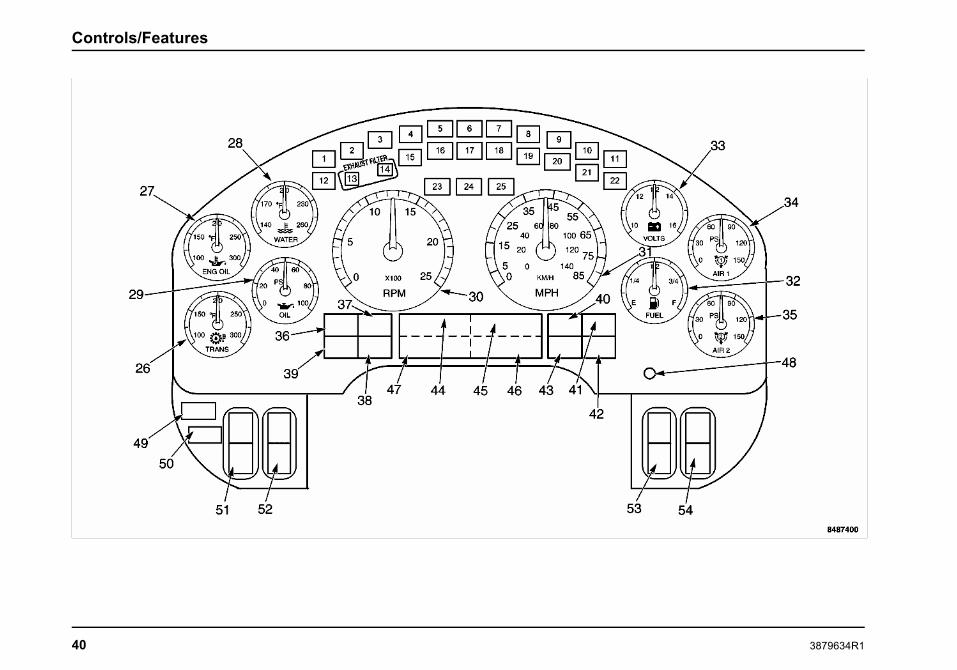
Controls/Features
40 3879634R1

Controls/Features
Warning Indicators
The instrument panel gauge cluster contains 25 individual LEDwarning indicators. These indicators are used to monitor vehicleoperation and indicate a WARNING or STOP condition. Thesewarning indicators are driven by the software in the instrumentpanel gauge cluster. At ignition, the warning indicators willilluminate for 8 to 10 seconds, as part of the vehicle power-upsequence.
ItemNo.
Item Description
1 Illuminates Yellow when the intakeheaters and glow plugs are in operationand special starting procedures arerequired. Refer to the Starting Switchparagraph in the Vehicle Operationsection for more information.
2 Illuminates Yellow to alert driver thatvehicle idle shutdown timer will turnengine off in 30 seconds.
3 Illuminates Yellow. Used in conjunctionwith other Warning Indicators or GeneralText and Warning Messages and maybe accompanied by an audible alarmto indicate an Alert condition to theoperator.
4 Illuminates Yellow. Used in conjunctionwith other Warning Indicators or GeneralText and Warning Messages to indicatean Alert condition to the operator.
5 Illuminates Red Used in conjunction withother Warning Indicators or General Textand Warning Messages to indicate a redSTOP alert.
6 Illuminates Red when a failure in theservice brake system has occurred. Ifthe Brake Pressure warning indicatorilluminates, safely stop the vehicle assoon as possible and seek serviceimmediately.
7 Illuminates Red when the parking brakeis applied. If the brake warning indicatordoes not illuminate, or if it stays on withthe parking brake not engaged, seekservice immediately.
8 Illuminates Green to assist operatorsin determining when it is appropriate toshift the transmission to a higher gear inorder to maximize driving fuel economy.
9 Illuminates Yellow when thetransmission is not engaged in theselected gear. The warning indicatorgoes out when the gearshift lever isadjusted to the appropriate gear. Referto the Transmission Operator’s Manualfor more information.
10 Not used.
3879634R1 41

Controls/Features
11 Illuminates Yellow when the tractioncontrol system is turned off. It alsoilluminates momentarily when thetraction control system is on and islimiting wheel spin. Indicator blinks ifslippery road conditions exist. If thishappens, adjust your driving accordingly.Refer to the Operation section for moreinformation.
12 Not used.
13 Illuminates Yellow when exhaust systemcomponents are operating under normalconditions and exhaust gases are atextremely high temperatures.
14 Diesel Particulate Filter (DPF) statusindicator. Illuminates Yellow (Solidor Flashing) to indicate the need toregenerate the Diesel Particulate Filter.(See Exhaust Regen in the VehicleOperation Section).
15 Engine Emissions Control SystemMalfunction Indicator Lamp (MIL)
Illuminates Yellow when an emissionsproblem has occurred.
16 Illuminates Red when a parking brakesystem malfunction has been detected.If the Service Parking Brake indicatorstays illuminated, have the systemserviced immediately.
17 Optional indicator illuminates Redimmediately after ignition is turned on toremind operator to fasten seat belt.
Optional Seat Belt Reminder with SeatBelt Monitoring causes initial visualindication, then flashes with audiblealarm when ignition is on, parking brakeis released, and seat belt is not fastened.
18 Illuminates Red when the brake fluidfalls below the safe operating level.
19 Not used.
20 Not used.
21 Illuminates Yellow when an antilockbrake system malfunction has beendetected. If the ABS indicator staysilluminated or continues to flash, havethe system serviced immediately.
22 Illuminates Yellow when transmissionEconomy Mode is selected. Refer tothe Transmission Operator’s Manual formore information.
42 3879634R1

Controls/Features
23 Flashes Green when the left turn signalor the hazard lights are turned on.
24 Illuminates Blue when the high beamhead lamps are turned on.
25 Flashes Green when the right turn signalor the hazard lights are turned on.
NOTE: If the MIL is illuminated, it is the vehicle owner’sresponsibility to have the engine repaired or face fines.
Gauges
There are six standard and four optional gauges in theinstrument panel gauge cluster to help monitor the vehiclewhile in service. Most gauges have in-gauge warningindicators which turn ON if the gauge pointer moves intoan out-of-acceptable-range condition. When the ignition switchis turned ON, the gauge indicators will be ON. If any indicatorfails to go out after starting engine, stop engine and determinecause of the gauge indication that is out of acceptable range.Metric versions of the gauges and speedometer are availableas an option.
ItemNo.
Item Description
26 Transmission Oil Temperature Gauge:Indicates the transmission lubricanttemperature in degrees Fahrenheit orCelsius.
27 Optional Engine Oil TemperatureGauge: Indicates the engine lubricanttemperature in degrees Fahrenheit orCelsius.
27 Optional Ammeter: Indicates the rateof charge of electric current supplied bythe alternator to the battery, or the rateof discharge from the battery.
28 Coolant Temperature Gauge:Indicates engine coolant temperature.
The warning indicator indicates theengine coolant temperature hasexceeded 230° F when equippedwith a 10 psi de-aeration tank, and235° F when equipped with a 15 pside-aeration tank. If the warning indicatoris activated, stop the vehicle as soon assafely possible, turn off the engine andlet the engine cool.
3879634R1 43

Controls/Features
ItemNo.
Item Description
29 Engine Oil Pressure Gauge: Indicatesengine oil pressure. If the needle fallsbelow the normal range (20–65 psi) atnormal operating temperature, stop thevehicle as soon as safely possible, andcheck the engine oil level. Add oil ifneeded. If the oil level is correct, haveyour vehicle checked by a qualifiedtechnician.
The warning indicator indicates lowengine oil.
30 Tachometer: Indicates the enginespeed in revolutions per minute.
31 Speedometer: Indicates vehicle speed.
ItemNo.
Item Description
32 Fuel Level Gauge: Indicates theapproximate fuel level in the fuel tank. Ifyour vehicle is equipped with dual fueltanks, the fuel gauge reads the fuel levelonly from the primary (draw) fuel tank.
When the fuel level reaches 1/8 full, thegauge warning indicator will illuminateand an audible alarm will sound (5beeps).
(Optional) Special fuel warning: thewarning indicator will light when gaugefalls below 1/3, and alarm continuouslywhen below 1/10 (close to ”E”).
33 Battery Voltage Gauge: Indicates thevoltage when the key is in the ON orACCESSORY position.
The warning indicator illuminates whenthe battery voltage is too high or low.
44 3879634R1

Controls/Features
ItemNo.
Item Description
34 Air Pressure Gauge 1: Providesindication of air pressure available forthe primary air brakes. LED and audibleunder-limit (less than 57 psi) warningindicators.
35 Air Pressure Gauge 2: Providesindication of air pressure available forthe secondary air brakes. LED andaudible under-limit (less than 57 psi)warning indicators.
Instrument Panel Gauge Cluster Alarms
WARNING
When an alarm sounds, stop normal vehicleoperation and determine the source of the alarmcondition. Failure to observe this instructioncould result in property damage, personal injury,or death.
The Instrument Panel Gauge Cluster will sound an audible alarmthat accompanies out of range gauge readings along with theparticular gauge warning indicators. The cluster alarms will alsosound when any engine sensor (sender) unit fails; when there isan electronics system fault; and when the Red engine indicator isilluminated. The following chart lists the number of alarm beepsfor the above conditions or warning states:
Alarm Conditions Audible Alarm Pattern Additional Comments
Fuel Level Gauge low (alarms on each ignition turn-on andlow fuel occurrence)
5 BEEPS Instrument Panel Gauge Cluster warning indicatorilluminates.
Voltmeter Gauge out of range reading 5 BEEPS
Engine Oil Pressure Gauge out of range reading 5 BEEPS
3879634R1 45
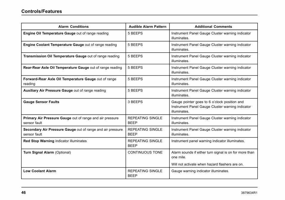
Controls/Features
Alarm Conditions Audible Alarm Pattern Additional Comments
Engine Oil Temperature Gauge out of range reading 5 BEEPS Instrument Panel Gauge Cluster warning indicatorilluminates.
Engine Coolant Temperature Gauge out of range reading 5 BEEPS Instrument Panel Gauge Cluster warning indicatorilluminates.
Transmission Oil Temperature Gauge out of range reading 5 BEEPS Instrument Panel Gauge Cluster warning indicatorilluminates.
Rear-Rear Axle Oil Temperature Gauge out of range reading 5 BEEPS Instrument Panel Gauge Cluster warning indicatorilluminates.
Forward-Rear Axle Oil Temperature Gauge out of rangereading
5 BEEPS Instrument Panel Gauge Cluster warning indicatorilluminates.
Auxiliary Air Pressure Gauge out of range reading 5 BEEPS Instrument Panel Gauge Cluster warning indicatorilluminates.
Gauge Sensor Faults 3 BEEPS Gauge pointer goes to 6 o’clock position andInstrument Panel Gauge Cluster warning indicatorilluminates.
Primary Air Pressure Gauge out of range and air pressuresensor fault
REPEATING SINGLEBEEP
Instrument Panel Gauge Cluster warning indicatorilluminates.
Secondary Air Pressure Gauge out of range and air pressuresensor fault
REPEATING SINGLEBEEP
Instrument Panel Gauge Cluster warning indicatorilluminates.
Red Stop Warning indicator illuminates REPEATING SINGLEBEEP
Instrument panel warning indicator illuminates.
Turn Signal Alarm (Optional) CONTINUOUS TONE Alarm sounds if either turn signal is on for more thanone mile.
Will not activate when hazard flashers are on.
Low Coolant Alarm REPEATING SINGLEBEEP
Gauge warning indicator illuminates.
46 3879634R1

Controls/Features
Direct Drive Warning Indicators
The direct drive warning indicators give information to theoperator of various conditions of the vehicle. Eight spaces areavailable for the direct drive warning indicators. Blank coverplates will be used in spaces that do not have direct drivewarning indicators installed at those locations.
ItemNo.
Item Color Description
36 Yellow WINTER/ENGINE INTAKEis set to the Winter position.
37 Yellow Front rear axle differentialis locked.
38 Yellow Rear rear axle differential islocked.
39 Yellow FRONT AXLE/ON switch isin the ON position.
40 BLANK Not used
40 BLANK Not used
41 BLANK Not used
41 BLANK Not used
42 Yellow AUTO NEUTRAL functionenabled.
ItemNo.
Item Color Description
43 Yellow Optional TransmissionRetarder switch is in the ONposition.
43 Yellow Illuminates in conjunctionwith the (Optional)Qualcomm satelitecommunication system– see Qualcomm systemowner’s manual.
Integral Digital Display
The Integral Digital Display is located below the speedometerand the tachometer. It is arranged in four quadrants that displayvehicle information. The four quadrants can be individuallyselected by using the display control button.
Display Control. The Display control is used to scroll to aquadrant and to select the various modes within a quadrant. Tonavigate between quadrants, turn and release the control eitherclockwise or counterclockwise. To select the screens within aquadrant, press and release the control. Pressing and holdingthe control for more than 3 seconds to reset the value of theselected quadrant parameter (if the parameter can be reset).The selected quadrant is identified by a vertical bar located inthe far right of quadrant. In quadrant 1, the odometer screencan be toggled between English and Metric, by pressing andholding the control.
3879634R1 47

Controls/Features
Item No. Quadrant Number and Message Function Message Description
44 Quadrant 4: Transmission Gear Indication Transmission gears for the Allison P-R-N-D-L gear selection display, or theEaton Transmission display.
45 Quadrant 1: Informational Messages Informational Display Screens:
• Odometer
• Trip Odometer
• Total Engine Hours
• Trip Hours
• Machine PTO A or B Hours
• Machine Trip PTO A or B Hours
• Engine PTO Hours
• Engine PTO Trip Hours
• Instantaneous Fuel Economy
• Trip Average Fuel Economy
• Machine PTO Fuel Used A or B
• Machine PTO Trip Fuel Used A or B
• Engine PTO Fuel Used
• Engine PTO Trip Fuel Used
• Trip Idle Fuel Used
• Axle Load Indication (Front and/or Rear)
• Diesel Particulate Filter Level
48 3879634R1

Controls/Features
Item No. Quadrant Number and Message Function Message Description
46 Quadrant 2: General Text and WarningMessages
Displays a variety of messages ranging in priority necessary for vehiclemonitoring and operation, and vehicle malfunction warnings. Some messagesare used in conjunction with instrument panel gauge cluster warning indicators(see list of messages in the Integral Digital Display section in Vehicle Operations)
47 Quadrant 3: Compass Heading/OutsideTemperature
(Optional) Displays compass heading when vehicle is equipped with a compassmodule.
Displays outside temperature (reading is obtained from the temperature sensor).
48 Display Control Toggles the information display from one screen to the next when pressedand released.
Switches
Six switches are located on the lower left and right side of themain instrument/control panel. Configurations are optional.Blank cover plates will be used in spaces that do not haveswitches installed at those locations.
Headlights
The headlights will be at 100 percent brightness with theheadlight switch activated. The park lights, tail lights, markers,and clearance lights will be on as well.
Your vehicle may be equipped with an optional headlight warningalarm that sounds immediately after ignition switch is turned toOFF position, when headlight switch is on, and the driver’s dooris closed. It also sounds when headlight switch is on, ignitionswitch is in OFF position, and the drivers door is open.
The headlights are operated in a variety of modes:
Daytime Running Lights (DRL)
The daytime running lights feature provides for low beamheadlights at 75 percent brightness whenever the ParkingBrake is released and the ignition switch is in the ON position.The lights will stay ON until the Parking Brake is engaged.
Lights on with Wipers
This feature allows the headlights (low beam) to be automaticallyturned ON when the windshield wipers are in steady orintermittent mode (not washer). The low beams will remainON until the ignition switch is turned to the OFF position or theheadlights are cycled ON and then OFF.
Park Lights
The park lights, taillights, markers, and clearance lights will turnON when the headlight switch is in the park or headlight position.
3879634R1 49

Controls/Features
Marker Interrupt
The marker interrupt function is an optional feature that togglesthe park lights and markers when the operator activates thespring-loaded marker interrupt switch. When park lights areON, activating the interrupt switch will cause the park lights andmarkers to be turned OFF until the interrupt switch is released.If park lights are OFF, activating the interrupt switch will causethe park lights and trailer markers to be turned ON until theswitch is released.
Panel Lighting
The panel lighting brightness is controlled by the Panel rockerswitch. To increase the brightness of the instrument panellighting, continually press the upper portion of the rocker switch.To dim the instrument panel lighting, continually press the lowerportion of the rocker switch.
Dome Lighting
The overhead dome light is used for reading and for illuminationwhen entering and exiting the vehicle. The dome light ON/OFFis also controlled by pushing on the lamp lens. When eitherentrance door is closed, the courtesy light will remain ON forapproximately 20 seconds or until the ignition switch is turnedON. At that time, the lights will dim gradually until the light is OFF.The optional keyless entry key fob also turns ON the light for atime period when its Unlock button is pressed and turns OFF thelight (dims gradually to OFF) when its Lock button is pressed.
Courtesy Lights
The optional driver courtesy lights are located under theinstrument panel ends for door lighting. This feature is providedwith the optional Premium trim package. An optional rearcourtesy light can also be provided with the travel crew cab.
50 3879634R1

Controls/Features
ItemNo.
Item Description
49 ConfiguredbyCustomerRequest
Switch options for this position include:
MIR, Fog Light Switch, and Plow Light switch.
NOTE: Refer to switch table in this section forswitch functions.
50 LMP Check
Activates the optional exterior lamp check.
51 Headlight/Park Lamp Switch
Activates the headlight or parking lights, andilluminates the instrument panel. This switchfunctions even when ignition switch is turnedOFF (a warning will sound when this switch isON and the ignition switch is OFF).
52 Panel Dimmer
Adjusts the panel lights brightness.
53
54
ConfiguredbyCustomerRequest
Switch options for this position include:
Lift Gate, Work Light, Mirror Heat, Fog Light,Plow Light, Fan Override, Two Speed Axle,Air Suspension Dump, Auxiliary, ParkedRegeneration, Inhibit Regen
NOTE: Refer to switch table in this section forswitch functions.
3879634R1 51

Controls/Features
Optional Instrument panel gauge cluster CompassCalibration Procedure
All new vehicles with an optional compass must have an initialcompass calibration performed. A compass calibration may ormay not have been completed at the vehicle assembly plant.If the compass headings are noticeably incorrect, or becomenoticeably incorrect, or the NO CAL message is displayed, theDeclination Zone may need to be reset to agree with the currentgeographic location, or the Compass Directional Calibration willneed to be recalibrated.
The compass direction is displayed in the lower left quadrantof the instrument panel gauge cluster display just below theoutdoor temperature reading. Text messages necessary tocalibrate the compass can be found in the instrument panelgauge cluster display in the lower right quadrant (quadrant 2)of the display. Twist the instrument panel gauge cluster displayknob until the cursor is flashing in the lower right quadrant.Press the instrument panel gauge cluster display knob untilthe desired text message is displayed. Compass Calibrationrelated text messages include “Calibrate Compass”, “CompassDeclination”, “Declination Zone #”, and “End Calibration”.
NOTE: The Declination Zone for the location where theCompass Calibration procedure is being performed must beset first, and thereafter the Compass Directional Calibrationprocedure can be performed. Both procedures are listed on thefollowing pages and must be followed exactly to ensure propercalibration of the compass.
Compass Declination Zone Set Procedure
The Declination Zone number is used to account for theerrors between magnetic North and true North in the vehicle’sgeographic operating area, and must be set correctly for thecompass to display accurate headings.
NOTE: When calibrating/recalibrating the compass, you mustselect the Declination Zone which corresponds to the geographiclocation where the compass calibration is being performed. Itcan be reset later to match the Declination zone where thevehicle will be operating.
For vehicles that regularly operate coast-to-coast or in severaldifferent Declination Zones, either choose a Declination Zone inthe geographic center of the vehicle’s operating area, or changethe Declination Zone daily to match the present DeclinationZone.
To begin the Declination Zone set procedure, the vehicle must bestopped with ignition key ON. Refer to Zone Map for determiningthe proper Declination Zone number.
52 3879634R1

Controls/Features
Declination Zone Map
3879634R1 53

Controls/Features
Step Procedure Displayed Message
1
Select Quadrant 2 (lower right) on the display by turning the display control knob eitherclockwise or counterclockwise.
2
Select the Compass Declination message by pressing and releasing the display controlknob until this message appears.
3
Press and hold the display control knob until any Declination Zone number (0 – 10) isdisplayed.
4
Turn the display control knob clockwise or counterclockwise until the desired DeclinationZone number is displayed. Refer to Declination Zone Map to determine the propernumber for the current geographic location.
NOTE: If no Declination Zone number is selected within 15 seconds, the display will returnto the Compass Declination message.
NOTE: If the compass is being calibrated/recalibrated the Declination Zone must be setto the Zone number for the location where the compass calibration/recalibration is beingperformed regardless of the location where the vehicle will eventually operate.
5
Press and HOLD the display control knob until the Compass Declination messageappears (this indicates that the new Declination Zone number has been programmedinto the compass).
54 3879634R1

Controls/Features
Compass Directional Calibration Procedure
To begin the Compass Directional Calibration Procedure, stopthe vehicle in an area large enough to permit driving in completecircles and perform the following steps:
Step Procedure Displayed Message
1
Select Quadrant 2 (lower right) on the instrument panel gauge cluster display by turningthe display control knob either clockwise or counterclockwise.
2
Select the Calibrate Compass message by pressing and releasing the display controlknob until this message appears.
3
Press and hold the display control knob until the End Calibration command is displayed.
NOTE: IF the End Calibration command will not show up, turn OFF the vehicle, restart it,and return to Step 1.
NOTE: The following steps (4 through 6) must be completed within 3 minutes to lock-inthe new calibration. Do not press the display control knob or turn the key OFF untilthese steps are completed or the calibration process will be cancelled.
4
Immediately following the End Calibration command being displayed, drive the vehicle in3 complete circles (during this time the compass display will go blank or have dashedlines present).
3879634R1 55

Controls/Features
5
Stop the vehicle and wait shortly. The End Calibration message should reappear onthe display.
6
Push and HOLD the display control knob until the End Calibration command disappears.The calibration should now be complete. IMPORTANT!: Just pressing and failingto hold the display control knob inward until the End Calibration commanddisappears will cancel the calibration procedure and you must start over at Step 1.
7
Test the compass calibration. Turn the vehicle ignition key OFF and then restart thevehicle. Wait 10 seconds to for the compass to complete its self test. Drive the vehiclein a circle and note the compass readings. If the lower left quadrant of the InstrumentPanel Gauge Cluster Display shows the correct compass/vehicle heading, the compasscalibration is now complete. If the compass readings are incorrect, inspect for correctDeclination Zone number, turn OFF the vehicle, restart the vehicle, wait 10 seconds, andperform another circle while periodically noting the compass readings. If readings arestill incorrect restart the compass calibration procedure.
Integral Digital Display Detailed Information
Quadrant 1: Informational Displays
NOTE: The available display screens are dependant on theconfiguration of the vehicle.
56 3879634R1

Controls/Features
Quadrant 1 – Display Messages Description
Odometer The odometer displays the total distance traveled.
Display Format:
100,000.0MILESKM
Trip Odometer The trip odometer displays a record of the elapsed distance traveled since the last reset.
NOTE: The trip hours and trip miles are independently reset.
Display Format:
100,000.0TRIP MILESTRIP KM
Total Engine Hours The Engine Hour display provides a record of accumulated engine hours, and will not show any increaseunless the engine is running.
NOTE: This display function cannot be reset.
Display Format:
100,000.0HOURS
Trip Hours The Trip Hour display provides a record of elapsed engine hours since the last reset.
NOTE: The trip hours and trip miles are independently reset.
Display Format:
100,000.0TRIP HOURS
3879634R1 57

Controls/Features
Quadrant 1 – Display Messages Description
Machine PTO A or B Hours This display will provide a record of the total accumulated Machine PTO hours, while PTO function Aor B is engaged.
Display Format:
100,000.0PTO HOURS APTO HOURS B
Machine Trip PTO A or B Hours This display will provide a record of the total accumulated Machine Trip PTO hours, while PTO function Aor B is engaged.
Display Format:
100,000.0PTO TRP HOURS APTO TRP HOURS B
Engine PTO Hours This display will provide a record of the Engine PTO hours sent from engine.
Display Format:
100,000.0ENG PTO HOURS
Engine PTO Trip Hours This display will provide a record of the Engine PTO Trip hours sent from engine.
Display Format:
100,000.0ENG PTO TRP HOURS
58 3879634R1

Controls/Features
Quadrant 1 – Display Messages Description
Instantaneous Fuel Economy This display provides a record of the instantaneous fuel economy sent from the engine.
The display shall be in miles per gallon or liters per 100 kilometers, corresponding to the units selectedwhile in the odometer mode.
Display Format:
30.0INST MPGINST L/100KM
Trip Average Fuel Economy The display value shall be the average fuel economy value since the last reset of the trip odometer.
The display shall be in miles per gallon or liters per 100 kilometers, corresponding to the units selectedwhile in the odometer mode.
Display Format:
30.0TRIP MPGTRIP L/100KM
Machine PTO Fuel Used A and B The display value shall be the calculated Machine PTO Fuel Used.
Display Format:
100,000.0PTO GAL APTO GAL BPTO L APTO L B
3879634R1 59

Controls/Features
Quadrant 1 – Display Messages Description
Machine PTO Trip Fuel Used A and B The display value shall be the calculated Machine PTO Trip Fuel Used.
Display Format:
100,000.0PTO TRP GAL APTO TRP GAL BPTO TRP L APTO TRP L B
Engine PTO Fuel Used The display value shall be the calculated Engine PTO Fuel Used.
Display Format:
100,000.0ENG PTO GALPTO TRP L
Engine PTO Trip Fuel Used The display value shall be the calculated Engine PTO Trip Fuel Used.
Display Format:
100,000.0ENG PTO TRP GALENG PTO TRP L
Trip Idle Fuel Used The display value shall be the calculated Trip Idle Fuel Used.
Display Format:
100,000.0TRP IDL GALTRP IDL L
60 3879634R1
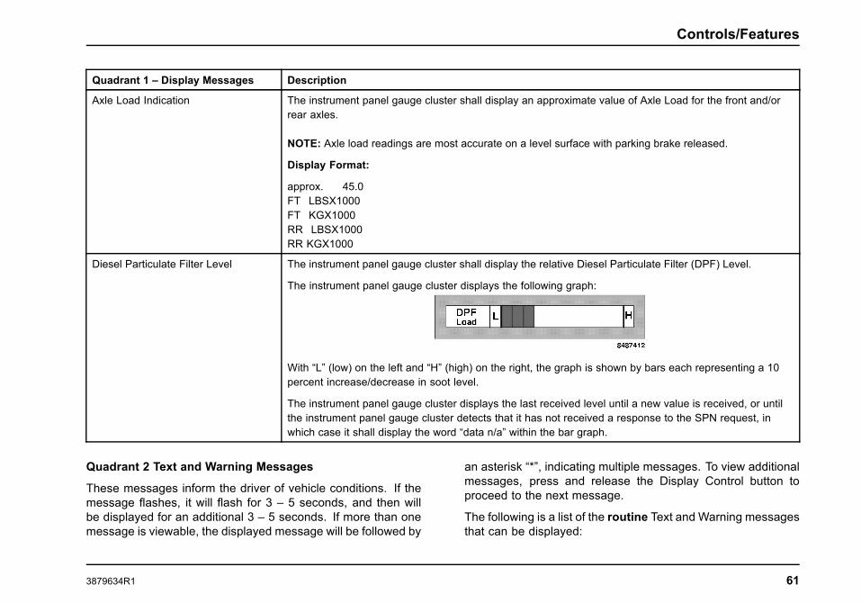
Controls/Features
Quadrant 1 – Display Messages Description
Axle Load Indication The instrument panel gauge cluster shall display an approximate value of Axle Load for the front and/orrear axles.
NOTE: Axle load readings are most accurate on a level surface with parking brake released.
Display Format:
approx. 45.0FT LBSX1000FT KGX1000RR LBSX1000RR KGX1000
Diesel Particulate Filter Level The instrument panel gauge cluster shall display the relative Diesel Particulate Filter (DPF) Level.
The instrument panel gauge cluster displays the following graph:
With “L” (low) on the left and “H” (high) on the right, the graph is shown by bars each representing a 10percent increase/decrease in soot level.
The instrument panel gauge cluster displays the last received level until a new value is received, or untilthe instrument panel gauge cluster detects that it has not received a response to the SPN request, inwhich case it shall display the word “data n/a” within the bar graph.
Quadrant 2 Text and Warning Messages
These messages inform the driver of vehicle conditions. If themessage flashes, it will flash for 3 – 5 seconds, and then willbe displayed for an additional 3 – 5 seconds. If more than onemessage is viewable, the displayed message will be followed by
an asterisk “*”, indicating multiple messages. To view additionalmessages, press and release the Display Control button toproceed to the next message.
The following is a list of the routine Text and Warning messagesthat can be displayed:
3879634R1 61

Controls/Features
Quadrant 2 – DisplayMessages
Description Flash (Yes/No) Warning IndicatorAssociation
PARKD REGEN ACTIVE Message is displayed during a parked regeneration. No No
Load Shedding Message is displayed when electrical load control andshedding feature is implemented.
Yes No
Washer Fluid Low Indicates low washer fluid level. Yes No
Electrical Fault When instrument panel gauge cluster’s ability to displaydiagnostic codes is enabled, this message is displayedwhen there are active diagnostic codes.
Yes No
Check A/C Indicates a fault in the HVAC System. Yes No
PARKD REGEN INHIBITED Message is displayed when parked regeneration has beenrequested, but is not performed due to a vehicle interlockor an engine fault.
No No
Air Filter Restriction Message displayed indicates restricted air flow to theengine.
Yes No
Exterior Lamp Check Active Message displayed indicates Exterior Lamp Check is inprogress.
Yes No
HVAC Temp Setting Bar graph displayed show temperature setting in low tohigh increments.
No No
Activate HVAC Front Blower Bar graph displayed show blower speed setting in Off andlow to high increments.
No No
62 3879634R1

Controls/Features
Quadrant 2 – DisplayMessages
Description Flash (Yes/No) Warning IndicatorAssociation
HVAC Sleeper Blower Speed Bar graph displayed show blower speed setting in Off andlow to high increments.
No No
Air Pressure Diagnostic Yes No
Cruise Indicates that the Cruise Control System is turned On. No No
Fuel Filter Indicates that the fuel filter is clogged. Yes No
Check Brake Switch Yes No
Check Pupil Warning Indicator Yes No
Check Stop Arm/Crossing Gate Yes No
Check Exterior Lamps Yes No
Engine Control Shutdown Yes No
Check Trailer Lights Yes No
Engine Control System Error Yes No
PARKD REGEN REQUIRED Indicates parked regeneration is necessary. No No
PARKD REGEN INHIBITEDENG TMP
Message is displayed when engine coolant temperature isbelow 170° F (76.6°C).
No No
REGEN INHIBIT SWITCHACTIVE
Message is displayed when Regen Inhibt Switch is “On”and regeneration Is disabled.
No No
PARKED REGEN AVAILABLE No No
Low Coolant Level Message is displayed when coolant level is less than orequal to 80%.
Yes No
3879634R1 63

Controls/Features
Quadrant 2 – DisplayMessages
Description Flash (Yes/No) Warning IndicatorAssociation
Stop Engine Message is displayed when Red Stop indicator isilluminated. MaxxForce® engine only.
Yes Red warning indicator
Warn Engine (Priority 1 or 2) (1) Message is displayed when MaxxForce, or MaxxForce®11/13 ECM turn on the Red warning indicator.
(2) Message is displayed when MaxxForce, or MaxxForce®11/13 ECM requests the Yellow warning indicator and notthe Red warning indicator.
Yes (1) Red warning indicator
(2) Yellow warningindicator
Stop Hybrid Message is displayed when Hybrid system turns on andrequests the Red warning indicator.
Yes Red warning indicator
Check Engine Message is displayed when ECM requests the Yellowwarning indicator and not the Red warning indicator.
Yes Yellow warning indicator
HV Batt Off-Line Message is displayed when Hybrid system battery is offline.
Yes No
Check Hybrid Message is displayed when Hybrid system turns on theYellow warning indicator while conditions for “HV BattOff-Line” message are not met.
Yes Yellow warning indicator
Low Engine Oil Level Message is displayed when engine oil level is less thanor equal to 80%.
Yes No
Change Engine Oil Message is displayed when engine oil change is detectedas necessary.
Yes No
Water in Fuel Message is displayed when water in fuel is present. Yes No
Refuel Message is displayed when fuel level is low. MaxxForce®11 and 13 engines only.
Yes No
High Fuel Temp Message is displayed when fuel temp is high. MaxxForce®11 and 13 engines only.
Yes No
64 3879634R1

Controls/Features
Quadrant 2 – DisplayMessages
Description Flash (Yes/No) Warning IndicatorAssociation
Electrical Fault (Priority 1 or 2) (1) Message is displayed when EGC requests the Redwarning indicator.
(2) Message is displayed when EGC requests the Yellowwarning indicator.
Yes (1) Red warning indicator
(2) Yellow warningindicator
Check Trans Message is displayed when transmission needs to beserviced.
Yes Yellow warning indicator
Trans Temp Message is displayed when transmission turns onthe Yellow warning indicator. Not available with alltransmissions.
Yes Yellow warning indicator
Gen Trns Flt Message is displayed when transmission turns on RedStop, MIL, or PROTECT, or the Yellow Warning indicatorwithout the conditions to display Check Trans, Trans Temp,Trans Oil Life, Trans Oil Filter, or Trans Service. Notavailable with all transmissions.
Yes Yes (see description)
Trans Oil Life Message is displayed when transmission oil needschanged. Not available with all transmissions.
Yes No
Trans Oil Filter Message is displayed when transmission oil filter needschanged. Not available with all transmissions.
Yes No
Trans Service Message is displayed when transmission needs service.Not available with all transmissions.
Yes No
DPF Ash Service Required Message is displayed when diesel particulate filter ashlevel requires service/cleaning.
Yes No
See Visor For Info Message is displayed indicates the particulate trapindicator must be on or must flash.
Yes Yes (see description)
3879634R1 65

Controls/Features
Quadrant 2 – DisplayMessages
Description Flash (Yes/No) Warning IndicatorAssociation
ECM, TCM, Shift Selector, ABS,Retarder – Driveline, EGC,Compass Module, ESC, VSM,SD, AGSP, TPMS, ExhaustModule, Telematics, AGSP 2,SIC 2, AGSP 3, SIC 1, PAM,Hybrid, Service Tool, Global
Message is displayed when a module other than theengine requests the red stop warning indicator.
Yes Red warning indicator
ECM, TCM, Shift Selector, ABS,Retarder – Driveline, EGC,Compass Module, ESC, VSM,SD, AGSP, TPMS, ExhaustModule, Telematics, AGSP 2,SIC 2, AGSP 3, SIC 1, PAM,Hybrid, Service Tool, Global
Message is displayed when a module other than theengine requests the Yellow warning indicator.
Yes Yellow warning indicator
Retarder Temp Message is displayed when instrument panel gauge clusterreceives signal from the Retarder – Driveline requestingthe Yellow warning indicator.
Yes Yellow warning indicator
Gen Rtrd Flt Message is displayed when instrument panel gauge clusterreceives signal from the Retarder – Driveline requestingthe Red warning, MIL, or PROTECT indicator, or theYellow warning indicator without the conditions to displayRetarder Temp..
Yes Yes (see description)
DRV Reward Expected No No
DRV Reward Good No No
DRV Reward Excellent No No
DRV Reward Penalty No No
66 3879634R1

Controls/Features
Quadrant 2 – DisplayMessages
Description Flash (Yes/No) Warning IndicatorAssociation
DRV Reward Increasing No No
DRV Reward Decreasing No No
VSL Ovrd Active No No
VSL Ovrd Expiring No No
Blank screen, available only when engine rpm less thanor equal to 325 RPM, or vehicle speed less than 2 mph(3 km/h).
No No
Calibrate Compass Message is displayed when vehicle speed is less than2 mph (3 km/h) and the operator has not requested“Calibrate Compass” in the current ignition cycle.
No No
End Calibration Message is displayed when vehicle speed is less than 2mph (3 km/h) and the operator has requested “CalibrateCompass” in the current ignition cycle.
No No
Calibration Ended Message is displayed when vehicle speed is less than 2mph (3 km/h) and the operator has requested “CalibrateCompass” in the current ignition cycle.
No No
Declination Zone Message is displayed only when vehicle speed is less than2 mph (3 km/h).
No No
Warning Messages
In addition to the Diagnostic Trouble Codes (DTC), the digitaldisplay will display a warning message whenever an Engineindicator is illuminated. This warning message will be toggledwith the normal DTC as follows:
Yellow Warning indicator: WARN ENGINE message
Red Stop indicator: Stop Engine message
The following chart provides the warning messages that aredisplayed along with corresponding Instrument panel gaugecluster indicators.
3879634R1 67

Controls/Features
MaxxForce® Engines
Warning indicator Warning Message
Red Stop Stop Engine
Yellow Warning Warn Engine
Quadrant 3: Display Messages
Outside Temperature and Compass Displays (Optional)
The optional Outside Temperature and Compass Heading isdisplayed in Quadrant 3. Typical displays for Temperature andCompass Heading are listed in the following table. The displayprovides both the outside ambient temperature and the relativedirection of the vehicle within a particular geographical zone.
Vehicle must be moving to acquire an accurate temperature.
Quadrant 3 –Display Messages
Description
OutsideTemperature andCompass Heading
Display Format:
Outside Temperature Reading
The Outside Temperature is displayed on the first line ofQuadrant 3 above the Compass Heading. The temperaturesensor is located near the front bumper. Due to its location,the sensor readings can be affected by road or engine heatduring idling or prevailing driving conditions (extended slowmovement).
The display will be in °F or °C, depending on the units selectedwhile in the odometer mode.
Quadrant 4: Transmission Gear Displays
Quadrant 4 – Transmission Gear Indications
Allison P-R-N-D-L geardisplay
Eaton® Transmission display
68 3879634R1

Controls/Features
Steering Wheel Controls
The steering wheel contains the Electric (city) horn, Optional Airhorn control, and Cruise/Throttle controls.
1 AIR HORN - Used to activate the airhorn.
2 HORN - Used to activate the city horn.
3 CRUISE/THROTTLE - ON/OFF - Turnsthe speed control feature ON or OFF.Engine speed does not change whenyou press the ON position. This controljust activates/deactivates the feature.When the OFF position is pressed, thesystem will be turned OFF.
4 RESUME/ACCEL - Used to resume thedesired speed set on the cruise controlor accelerate to a higher desired speed.When parked, used to increase idleRPM.
Cruise Control
The cruise control systems for all electronic engines function ina very similar manner. The biggest difference is the minimumand maximum allowable cruise control speeds that will vary fromvehicle to vehicle.
WARNING
Do not use the cruise control system whenunpredictable driving conditions are present.Such conditions include heavy traffic, roadsthat are winding, icy, snow covered, slippery,or with a loose surface. These conditions maycause wheel slippage and loss of vehicle control,resulting in property damage, personal injury, ordeath.
3879634R1 69

Controls/Features
Basic Functions of Steering Wheel Controls
The CRUISE/THROTTLE - ON/OFF control turns thespeed control feature ON or OFF. Engine speed does notchange when you press the ON position. This control justactivates/deactivates the feature. When the OFF position ispressed, the system will be turned OFF.
The left side CRUISE/THROTTLE switch has different labels,depending on which feature was ordered. However, they allperform the same function: to turn ON the basic feature.
The two available options are:
• Throttle - used when only throttle or an engine speed controlis ordered;
• Cruise/Throttle - used when cruise control and either a handthrottle or an engine speed control are ordered.
The right switch (SET/COAST - RESUME/ACCEL) actually setsand controls the engine speed. But if the left switch has not beenactivated, nothing will happen when pushing on this right switch.This switch has the same label in all applications.
Operational Procedures
The following steps will activate and enable each of the fourengine speed control features.
Cruise Control – operates like an automotive cruise control.
1. Press the ON position of the CRUISE/THROTTLE -ON/OFF steering wheel control.
2. Bring the vehicle to the desired operating speed (above35 MPH), and then push the SET/CRUISE position ofthe steering wheel control.
3. Once in the cruise mode the right side SET/CRUISE– RESUME/ACCEL switch can be used to increase ordecrease vehicle speed by pressing and holding theRESUME/ACCEL to increase or the SET/CRUISE todecrease vehicle speed.
4. A slight tap on the brake or clutch pedal will deactivatethe cruise but holds the selected speed in memory. Toreturn to this speed, just press RESUME/ACCEL.
5. When you press the OFF (left) position of theCRUISE/THROTTLE - ON/OFF switch, or if the vehicleis shut off, the selected speed setting is canceled.
Throttle
This feature is ordered to provide variable engine speed controlprimarily for operation of PTO powered equipment. It uses thesame Cruise controls as described below.
1. Press the CRUISE/THROTTLE - ON/OFF steeringwheel control to ON.
2. Press SET/CRUISE on the steering wheel control.
3. Press and hold RESUME/ACCEL to increase enginespeed until the desired engine speed is obtained. Or,you can repeatedly press and release RESUME/ACCELto increase the speed in small increments.
70 3879634R1

Controls/Features
4. To change from this initial setting, use the appropriatecontrol to raise or lower the engine speed as you wouldin the cruise control mode. SET/CRUISE reducesengine speed and RESUME/ACCEL increases enginespeed.
5. Press the OFF position of the ON/OFF control to turnthe throttle off and return the engine to idle.
Stationary Variable Speed Control (12VXT)
This feature is ordered to provide variable engine speed controlprimarily for operation of PTO powered equipment. It operatesthe same as the Cruise/ Throttle controls discussed above.
Stationary Pre-Set Speed Control (12VXU)
1. To activate this feature, press the ON position on the leftside CRUISE/THROTTLE - ON/OFF switch.
2. When ordered, this feature can provide two differentpredetermined speeds, which are selected with theSET/CRUISE or RESUME/ACCEL positions. You needto know which position to use for your specific operation.Press the right side SET/CRUISE or RESUME/ACCELswitch for the desired pre-set speed.
3. First, press the switch that selects one of the desiredspeeds.
4. To select the other speed, press the other switch. Theengine will immediately return to idle.
5. You must push the switch a second time to go to thesecond speed. This is done to protect equipment frombeing inadvertently operated at the wrong speed.
Mobile Variable Speed Control (12VXV)
Operates the same as cruise control, except the engine speed isaccurately controlled instead of vehicle speed. The truck couldbe operated in one of several gears but the truck is limited toa maximum of 20 MPH, or any pre-set lower speed down to 3MPH.
3879634R1 71

Controls/Features
Steering Column and Switches
The steering column contains switches and levers to aid in thecomfort of the operator and to assist the operator while drivingthe vehicle.
1. Washer/Wiper Control - The windshield washer, along withthe windshield wipers, is controlled by the WASHER/WIPERknob on the turn signal switch lever. To operate the windshieldwasher, push in on the wiper knob to spray solution on thewindshield. Wipers will start wiping and continue for two cycles.
Multi-function Switch - The multi-function turn signal switchis mounted on the left side of the steering column below thesteering wheel.
2. Signaling For A Turn - When signaling your intention to makea turn, move the turn signal lever up or down to the “full turn”position which is past the point of resistance. On some modelsthe switch will automatically cancel if the steering wheel is turneda large enough degree. On other models the switch does notautomatically cancel and will require manual cancellation.
Lane Change – The turn signal lever includes a “lane change”feature which allows the operator to signal the intention tochange lanes without locking the switch into the full turnposition. To use this feature, move turn signal lever up or downto the point where resistance to movement is felt. The turnsignal lever will return to the OFF position when released.
3. Windshield Wiper - The electric wiper has two speeds(hi-low), which can be operated by rotating the WASHER/WIPERknob. The optional intermittent control provides five wiperON/OFF cycle intervals, varying from 2 to 14 seconds. This isdone by rotating the wiper control from the wiper OFF positionto the any of the five intermittent wiper interval positions.
Automatic Intermittent Interval Control (Optional) – Thisfeature automatically changes the wiper speed from HIGH orLOW to the slowest intermittent speed when the parking brakehas been set, and the wipers have been on for a predeterminedlength of time. When the parking brake is released, the wipersreturn to their previous speed.
72 3879634R1
Controls/Features
WARNING
Do not use the washers in freezing weatherwithout first warming the windshield with thedefrosters; otherwise, the washer solution mayfreeze on the windshield and obscure your visionand cause an accident which could result inproperty damage, personal injury, or death.
Do not use radiator coolant or anti-freeze in thewindshield washer reservoir. Radiator coolantin the washer reservoir can severely reducevisibility when sprayed on the windshield.
Keep the fluid reservoir filled with Fleetrite® Windshield WasherSolvent or equivalent.
4. Low/High Beam - When the turn signal stalk is pulled pastthe “click” position, lights will switch to Hi-Beam position. Whenpulled again they will revert to Lo-Beam.
Headlight Flash-To-Pass - When the turn signal lever is pulledwith the headlights OFF, the Hi-Beam lights will come on and stay
on as long as the lever is held in the pulled position. When theLo-Beam headlights are ON, the Hi-Beam lights can be made toflash if the lever is not lifted past the ”click” or dimmer position.
5. Hazard Warning Switch - Red rocker switch located abovemultipurpose turn signal lever. Push switch to forward position toactivate. The hazard warning flasher will operate with the ignitionswitch in the ON or OFF position. Use the warning system anytime your vehicle becomes a traffic hazard, day or night. Pushswitch rearward to deactivate.
Stop Override Hazard (Optional) - When hazard lights areactivated and the brake pedal is depressed, all hazard/turnsignal lights on the front, side lights of the truck, and the sidetrailer lights will continue to flash. The rear lights of the truck ortractor will burn steadily until the brake is released.
6. Tilting Adjustment Lever (Optional) - Allows the steeringwheel placement to be adjusted for driver comfort. Pull up toadjust, push down to lock.
7. Trailer Brake Lever - This lever is used to apply and releasethe brakes to the trailer.
3879634R1 73

Controls/Features
Center Dash Panel/Wing Panel
The Center Control Switch Panel consists of the switchesthat start the vehicle, control the vehicle’s normal operations,vehicle lights, and special mechanical functions. The panel alsoincludes control of the interior comfort levels (HVAC controls),optional parking brake controls and auxiliary electrical powersource (see Vehicle Operation for operational details). Referto the Radio Operator’s Manual provided with the vehicle forinstructions on operating the radio installed in this Vehicle.
1. Radio
2. Fan Speed Control
3. Temperature Control
4. Mode Control
5. Storage Compartment/Optional Switch Pack Location
6. Parking Brake
7. Optional Component Panel
8. Trailer Air Supply
9. Optional Switch Pack Location
10. Ignition Switch
11. Switch Pack
74 3879634R1

Controls/Features
Switches
Up to 25 optional switches can be located in the center and lowerright side of the center dash panel. Location of these switcheswill vary depending on the options installed. Blank cover plateswill be used in spaces that do not have switches installed at thoselocations.
Item DescriptionMarker Interrupt – MKR INTR
A momentary switch that turns all trailer marker lightsON or OFF, depending on park light switch position.
Heated Mirror – ON/OFF
A momentary switch that, when pushed and released,turns the mirror heating element ON or OFF.
ENG BRAKE – ON/OFF
Turns engine compression brake ON/OFF.
ENG BRAKE 1/2/3
A three position switch that selects the amount ofengine braking (1 = Low, 2 = Medium. 3 = High)
Transmission Retarder – RTARDR ON
Turns ON transmission retarder to slow down drivetrain.
Transmission Retarder – HI/LOW
Selects the percentage of Transmission Retardercapability. HI = 66%; LOW = 33%.
FOG LIGHT – ON/OFF
Turns ON Fog Lights when the switch is in the ONposition, ignition switch is in the “Ignition” or “Start”position, and the headlights are ON and in low beammode.
TRAC ENAB/DISAB
This switch enables or disables the ABS traction feature.
OFF ROAD ENABLE
As part of the automatic traction control system, thisswitch, when enabled, allows for greater engine powerand more wheel spin on soft road surfaces.
3879634R1 75

Controls/Features
MUD/SNOW ENABLE
As part of the automatic traction control system, thisswitch, when enabled, allows for greater engine powerand more wheel spin on soft road surfaces.
PLOW LIGHT ON/OFF
With this feature, the ON position selects the highmounted Plow lights whenever the headlights are ON. Ifthe operator shuts OFF the vehicle with the plow lightsON, they will remain ON.LIFT GATE – ON
This switch provides power to the lift gate system.
This optional feature provides battery protection and/orprogrammable time out.AUTO NEUTL – ON
When the ON position is selected and the parkingbrake is applied (vehicle speed is near zero mph), thetransmission goes into (auto) neutral.
FAN OVRD – ON
With the switch in the ON position, the fan mode isswitched from “auto” to the constant “on”.
The switch indicator will be ON when the ON positionis selected.WORK LIGHT – ON
This switch is used to turn the back of cab work lightON or OFF.
2 Speed Axle – 2 SPD LO/ 2 SPD HI
A 2 speed switch that allows the operator to selecteither high or low rear axle ratio.
Power Divider lock – LOCK/PDL
This switch is used to lock together the front and rearaxle of a tandem.
SUSP/DUMP
This switch allows the operator to release the air fromor reinflate the air bags of the air suspension system.
PTO OFF/ON
Engages Power Take Off when switch is in ON positionor disengages Power Take Off when switch is in PTOOFF position.
5TH WHEEL SLIDE ON/OFF
This switch, when set to ON, releases the sliding 5thwheel (when ignition switch is in “Run” and vehiclespeed is less than 2 mph).
Differential Lock – DIFF/LOCK
This switch, when set to LOCK, engages the lockingdifferential which locks the right and left side tires (only ifvehicle is below maximum differential lock engagementspeed of 25 mph (40 km).
76 3879634R1

Controls/Features
Forward Rear Tandem Axle Differential Lock – DIF FRAXLE LOCK
This switch, when set to LOCK, engages the forwardrear locking differential for improved traction on poorsurfaces (only if vehicle is below maximum differentiallock engagement speed of 25 mph (40 km).Rear Rear Tandem Axle Differential Lock – DIF RRAXLE LOCK
This switch, when set to LOCK, engages the rearrear locking differential for improved traction on poorsurfaces (only if vehicle is below maximum differentiallock engagement speed of 25 mph (40 km).Front Axle Differential Lock – FRONT AXLE/ON
Engages Front Axle for 4X4 operation.
Transfer Case – XFER HI/XFER LOW
Selects Transfer Case high or low gear ratio.
AIR ASSIST – (OFF) ON
Provides inflation or deflation of auxiliary air bag.
Engine Shutdown Override – ENG OVRD/ON
This momentary switch, when pushed to the ONposition, will allow the vehicle to be restarted in theevent of an automatic engine shutdown.
AC Power Enable – ON 120V AC
This switch, when set to the ON position, will provideAC output from the Power Pack 3 inverter.
WINTER/ENGINE INTAKE
Used to change engine intake air from “outside air” toengine compartment air.
PARKD REGEN – ON
DPF regeneration activation when parked switch isused for engine after-treatment. Manually initiates DPFregeneration.
INHIBT REGEN – ON
The Regeneration Inhibit switch is used to preventthe Active Regeneration or Parked Regenerationprocesses.
ENAB/DATA LOG
When enabled, allows the driver to log the last fiveseconds of data group’s operational parameter valuesinto ECM memory.
3879634R1 77

Controls/Features
Auxiliary Gauge/Switch Package (AGSP)(Optional)
The Auxiliary Gauge/Switch Package provides locations forthree additional gauges and six switches for optional customerrequirements. The following lists the gauges that are approvedfor this location.
1. Auxiliary Gauge Locations
2. Auxiliary Switch Locations
Optional Gauge Function
Air Application Gauge Provides readings of brake applicationair pressure. Max pressure of 150 psi.
Optional Gauge Function
Ammeter Gauge Provides reading of battery and alternatorcurrent in Amps.
Rear–rear AxleTemperature Gauge
Provides monitoring of temperature ofaxle lubricant. Warning indication at230°F.
Front–rear AxleTemperature Gauge
Provides monitoring of temperature ofaxle lubricant. Warning indication at230°F.
Load Indicating Gauge Provides reading of rear axle load. *
* Gauge reading is for reference only. DO NOT base legalloading criteria on this gauge reading.
Refer to Switches in this section for optional auxiliary switches.
Panel Component Arrangements (Optional)
Item Component Description
1 Two Post Power Socket
78 3879634R1

Controls/Features
Item Component Description
2 Cigar Type Power Socket
3 Optional Filter Minder
4 Three Switch Pack
a. Optional Winter/Engine IntakeSwitch
b. Optional Air Horn Switch
c. Optional Ether Start Switch
d. Optional Engine Start Switch
e. Optional Axle Enable Switch
f. Optional Axle Up/Down Switch
g. Optional Roof Auxiliary Switch
Item Component Description
5 Telematics No Data Logged Switch
6 Telematics Driver Alert Switch
7 Cigar Lighter
3879634R1 79

Controls/Features
Climate Control
WARNING
Never drive the vehicle unless the windshield and all other windows are clear. A fogged, ice/snow covered, or dirty windshieldor window limits vision, which could cause an accident, resulting in property damage, personal injury, or death. To improvedefroster efficiency, remove ice and/or snow by hand from the windshield and windows with a non-metallic scraper.
CAUTION
To clear system of humid air, operate blowers for 30 seconds at high speed, with the AIR FLOW/AIR CONDITIONER knob on thenormal heating position before selecting the DEF position. This will prevent fogging the glass, which can occur if humid air isblown onto a cool windshield.
NOTE: The vehicle may be equipped with optional heater shut off valve(s) to prevent hot coolant from circulating through the heater core(s). Closingthe valve(s) during hot weather operation will improve A/C system performance. If the valves are shut off, in-cab temperature adjustment may becomelimited. In addition, when shut off valves are closed, defrosters will only produce cold air.
Item No. Item Description36 Fan Speed Control Use this control to regulate the amount of air provided to the vents in any mode you select. Turn
the knob clockwise to increase fan speed. Turning the control to the OFF position will shut OFFthe fan (and the A/C compressor if A/C is selected), but does not prevent outside air from enteringthe vehicle. On vehicles equipped with A/C, moving the mode knob to the MAX A/C position, withthe fan ON, will close the fresh air door eliminating outside air from entering the vehicle.
37 Temperature Control Use this control to regulate the temperature of the air discharged from the vents. The blue area ofthe control indicates cooler temperatures, while the red area indicates warmer temperatures.
38 Mode Control NOTE: The dot between the mode control icons is an additional mix position between the twomodes.
Use this control to direct the flow of air as follows:
80 3879634R1

Controls/Features
MAX Air Conditioning Mode
In this mode, all airflow is directed to the panel air outlets and the air is recirculated inside thevehicle. Use this mode to block out any outside odors, smoke, or dust and to cool the interiorrapidly upon initial start up in very hot or humid weather.
NOTE: Continuous use of the recirculation mode may make the inside air stuffy. Use of this modefor longer than fifteen minutes without a window slightly open is not recommended.
The A/C compressor turns ON and OFF automatically as needed when in this mode.NORM Air Conditioning Mode
In this mode, all airflow is directed to the panel air outlets. Fresh (outside) air is used to cool thevehicle in this mode.
The A/C compressor turns ON and OFFautomatically as needed when in this mode.
Bi-Level Air Conditioning Mode
In this mode 75 percent of the airflow is directed to the panel air outlets and 25 percent of theairflow is directed to the floor air outlets, and fresh (outside) air is circulated inside the vehicle.
The A/C compressor turns ON and OFF automatically as needed when in this mode.
Vent Mode
In this mode, all airflow is directed to the panel air outlets, and fresh (outside) air is circulatedinside the vehicle.
Floor Mode
In this mode, all airflow is directed to the floor air outlets, and fresh (outside) air is circulatedinside the vehicle.
3879634R1 81

Controls/Features
Mix Mode
In this mode 50 percent of the airflow is directed to the defrost and side demist air outlets and50 percent of the airflow is directed to the floor air outlets, and fresh (outside) air is circulatedinside the vehicle.
The A/C compressor turns ON and OFF automatically as needed when in this mode to reducehumidity levels and help reduce moisture buildup on the windshield.Defrost
In this mode, all of the airflow is directed to the defrost and side demist air outlets, and fresh(outside) air is circulated inside the vehicle.
The A/C compressor turns ON and OFF automatically as needed when in this mode to reducehumidity levels and help reduce moisture buildup on the windshield.
To remove stale air or smoke while air conditioner is operating, you may want to open a vent window for a short period of time. Always park inthe shade when possible. If your vehicle has been parked in the sun with the windows up, remove the overheated air inside by driving withwindows down and the air conditioner ON for one or two city blocks.
Air Conditioning
CAUTION
Failure to follow recommended serviceprocedures and maintain adequate air flowthrough air exchange devices may resultin component failure. Cleaning should beperformed by a qualified technician.
Keep radiator area free of bugs, leaves, etc. Do not cover thecondenser with a wire screen.
At least once or twice a month, turn ON the air conditioner for afew minutes while the engine is running. This periodic operation
keeps all the mechanical parts of your air conditioner in goodoperating condition.
It is normal for small amounts of water to drain out of the airconditioner module. This water is condensed moisture removedfrom the air inside the vehicle.
Correct airflow may be restored by either replacing the filter(s),which can be done without tools, or by cleaning the filters. Thefilter(s) may be cleaned by using a power washer with a soapsolution. Keep the spray head at least six inches away from thefilter to avoid damage. Rinse thoroughly.
82 3879634R1

Controls/Features
NOTE: If your air conditioning performance seems lowerthan expected, check the front of the A/C condenser for anaccumulation of dirt or insects. Clean with a gentle water sprayfrom behind the radiator and through the condenser as required.Check for dirt and debris in both the cab and sleeper HVACintake filters that may reduce airflow.
NOTE: The air conditioning system incorporates a low-pressureswitch, which disengages the compressor clutch if evaporatoroutlet pressure falls below a certain set point. To restart the airconditioning system after an automatic shutdown has occurred,the operator must do one of the following:
1. Set A/C control to OFF and then back to ON. Fan speedcontrol knob MUST NOT be in the OFF position.
2. Place fan speed control knob in OFF position and thenback to the desired speed setting. A/C system must beON.
NOTE: If the system continues to shut down automatically, havethe system checked.
NOTE: The vehicle may be equipped with optional Heater ShutOff Valve(s) to prevent hot coolant from circulating through theheater core(s). Closing the valve(s) during hot weather operationwill improve A/C system performance. If the valves are shut OFF,in-cab temperature adjustment may become limited. In addition,when shut off valves are closed defrosters will only produce coldair.
Dehumidification
The heater/defroster systems can be operated simultaneouslywith the air conditioner during mild weather and high humidityconditions to dehumidify the cab air. Turn the mode button toone of the A/C positions and position the temperature knob ata comfortable temperature location. The air conditioner willremove the humidity while the heater keeps the cab comfortable.
Door and Window Controls
Door Lock/Unlock
Cab Doors and Locks
The cab doors can be unlocked with the same key used for theignition lock. There is also a keyless remote entry available.
NOTE: The vehicle is delivered with two identical keys. Ifmore keys are needed, order them through your authorizedInternational dealer. Record the key code and keep it in asecure place. A new key can be made if the keys are lost.
3879634R1 83

Controls/Features
1. Door Handle
2. Key Lock
3. Interior Lock
4. Interior Door Handle
To open any door from inside,pull out on interior doorhandle.
To open any door fromoutside, grab door handleand pull downward.
With mechanical locks, only one door can be locked/unlocked ata time. Electrical locks can lock/unlock both doors by operatingeither the key, keyless entry fob, or the inner door lock handleon either side.If equipped with a crew cab, the rear door locks, when engaged,must be unlocked using the mechanical lock release or theswitch for electric locks. The rear interior door handle will notdisengage the door locks.
Remote Keyless Entry Operation (Optional)
The remote keyless entry key fob is used to lock and unlock alldoors from a distance of 30 feet (9 m) or less. Whenever thedoors are locked or unlocked using the key fob, the city hornsounds momentarily (chirps). Also, the remote keyless entry keyfob turns ON the interior light for a time period when the Unlockbutton is pressed, and turns OFF the light (dims gradually toOFF) when the Lock button is pressed. The Panic (emergency)button, when pushed, causes the horn to chirp ON/OFF for threeminutes in unison with the headlights and park lights flashing.This feature works only when the ignition switch is in the OFFposition.
The auxiliary button will be used to toggle the optional work lightON or OFF (if OFF, it will be turned ON, and if ON, it will be turnedOFF).
84 3879634R1

Controls/Features
NOTE: This device complies with Part 15 of the FCC Rules andwith RSS-210 of Industry Canada. Operation is subject to thefollowing two conditions:
1. This device may not cause harmful interference.
2. This device must accept any interference received,including interference that may cause undesirableoperation.
Changes or modifications not expressly approved by the partyresponsible for compliance could void the user’s authority tooperate the equipment.
Door Opening/Unlock
Enter or exit the vehicle by manually pulling on the exterioror interior door handles. To open the door from the interior, iflocked, the front door will unlock when the door handle is pulled.
If equipped with a crew cab, the rear door locks, when engaged,must be unlocked using the mechanical lock release.
Lock/Unlock from Interior
WARNING
To help reduce the risk of personal injury in theevent of an accident, keep doors locked whenvehicle is in motion.
1. Lock/Unlock Button
2. Door Control Panel
3. Driver Side Power Window Control
4. Passenger Side Power Window Control
5. Window Lock Control
Locking the Door
To lock, push the lock/unlock button on the lock symbol in thedoor control panel located by the vent window. Pressing thelock/unlock button on the lock symbol once locks both cab doors.
3879634R1 85

Controls/Features
Unlocking the Door
To unlock, push the lock/unlock button on the unlock symbol inthe door control panel located by the vent window. Pressing thelock/unlock button once on the unlock symbol unlocks the driverdoor. Pressing it twice unlocks both doors.
Automatic Door Lock Function
The automatic lock function automatically locks the doors at apredetermined speed.
Windows
Manual Operation
To lower door glass (driver door), turn window regulator handleclockwise. To raise glass, turn handle counterclockwise.Reverse this procedure for the passenger door.
Power Operation
Trucks may have optional electrically-operated driver andpassenger windows. Controls for these window lifts aremounted in the door control panels located by the vent windows.The driver side controls regulate window operation for bothdriver and passenger. To lower or raise driver window, pressand hold either “Up” or “Down” direction on the driver side AUTOwindow control. To lower or raise passenger window, pressand hold either “Up” or “Down” direction on the passenger sideAUTO window control.
For one-touch windows down operation, press and release thewindow control in the “Down” direction. The window will then goto the full down position automatically.
Window Lockout Function
The driver also has the ability to prevent passenger windowup/down operation by pressing the WINDOW LOCK control.
Mirror Controls
1. Mirror Select Switch
2. Mirror Direction Control Switch
86 3879634R1

Controls/Features
These controls provide the driver with the ability to operate bothdriver- and passenger-side flat mirrors. Use the mirror selectswitch to select which mirror is to be adjusted and adjust themirror using the mirror direction control switch.
Vent Window
Vehicles are equipped with either a fixed or opening vent window.The opening vent window can be opened and closed to allowadditional airflow into the cab.
Driver Reward
The driver reward feature is designed to give the operatorincentives for driving more efficiently. This is accomplished bymeasuring the driver’s habits based on fuel economy, time atidle, or both. Rewards include higher maximum vehicle speedand higher cruise control speed limit. Lower maximum vehiclespeed or cruise control speed limits may result as a penalty forfailing to meet the standards.
The following driver reward visual indications appear in the formof text messages in the gauge cluster digital display:
• Expected – Reward indication which results in higher vehiclespeed limits.
• Good – Reward indication which results in higher vehiclespeed limits.
• Excellent – Reward indication which results in higher vehiclespeed limits.
• Penalty – Penalty indication which results in lower vehiclespeed limits.
• Increasing – Informs the driver that the vehicle speed limitwill soon be increased.
• Decreasing – Informs the driver that the vehicle speed limitwill soon be decreased.
3879634R1 87

Controls/Features
88 3879634R1

Operation
SECTION 5 — OPERATIONOperation Safety
WARNING
Operation of a diesel engine near flammablevapors in the air may cause the engine speedto increase uncontrollably and overspeed. Ifthis situation occurs, mechanical damage, fire,explosion, personal injury or death could result.Turning off the ignition switch will not slow orstop the engine due to uncontrollable fuelingof the engine through flammable vapors beingdrawn into the engine air inlet. Operation ofcomponents such as starter, alternator, electricmotors, etc. and static electricity could alsoignite flammable vapors.
Do not operate the truck in the possible presenceof flammable vapors unless both a completehazard analysis is performed and necessaryadditional safety processes and/or equipmentsuch as vapor testing, air intake shutoff devices,ventilation, etc. are utilized. The operator isresponsible for using those processes and/orequipment to ensure that the diesel engineand all other components on the truck can beoperated safely under the specific conditionsand hazards that may be encountered.
WARNING
Do not exceed the truck’s gross axle weight,gross vehicle weight, and gross combinationweight ratings. Exceeding these ratings byoverloading can cause component failureresulting in property damage, personal injury, ordeath.
WARNING
Always use occupant restraint system whenvehicle is moving. Any location in the vehicle notequipped with a seat belt should not be occupiedwhen the vehicle is being operated. In the eventof a vehicle accident or sudden, unexpectedmovement, failure to properly use an occupantrestraint system could result in personal injuryor death.
WARNING
Always use the ashtray(s) provided for disposingof cigar, cigarette, or pipe ashes and tobacco.Failure to use an ashtray is a fire hazard andcould result in property damage, personal injury,or death.
3879634R1 89

Operation
WARNING
When parking your vehicle, do not leavetransmission in gear. Always use parking brake.When parking on a grade, chock wheels andturn front wheels to keep the vehicle from rollinginto the traveled portion of the roadway. Failureto follow these procedures could cause anunattended vehicle to move, resulting in propertydamage, personal injury, or death.
WARNING
Exhaust gases from engines contain hazardouscompounds. Do not operate engines in enclosedareas without abundant forced ventilation (withgarage doors and windows wide open). Maintainexhaust system in good operating condition.Breathing exhaust gases could result in personalinjury or death.
WARNING
All vehicles have blind spots. Make sure yourway is clear in all directions before moving yourvehicle. Failure to follow these procedures couldresult in property damage, personal injury, ordeath.
This section contains information concerning the safe operationof your vehicle. It is extremely important that this information isread and understood before the vehicle is operated.
Cab Controls
The cab controls and features are described in detail inthe Controls/Features section of this manual. Read andunderstand the entire Controls/Features section of this manualbefore operating this vehicle.
90 3879634R1

Operation
Seat Belts
WARNING
To prevent personal injury or death, do not ridein the vehicle cargo area or on the outside ofthe vehicle. Ride only in designated seatingpositions or sleeper berth with seat belts or bunkrestraints fastened and properly adjusted.
WARNING
Failure to properly inspect and maintain seatbelts could result in personal injury or death.
WARNING
Any seat belt in use during an accident mustbe replaced. When replacement of any part ofthe seat belt is required, the entire belt must bereplaced, both retractor and buckle sides. Beltfailure could result in personal injury or death.
NOTE: Periodically inspect the seat belts for wear and function.Replace any parts whose performance is in doubt.
General
Safety belts must be worn by the driver and all passengers atall times. Before adjusting or fastening the safety belt, movethe seat forward or backward and adjust the seat height asnecessary. Sit erect and adjust the seat cushion and seat backfor a comfortable driving position. In the event of a collision,a correct driving position maximizes the effectiveness of thesafety belt.
Tether straps are installed on all suspension-type seats. Tetherstraps help secure the seat to the floor and are intended torestrain the seat and safety belt in case of an accident orsudden stop. The tethers are not adjustable and do not needany adjustment.
3879634R1 91

Operation
Operation
1. Three-Point Seat Belt
2. Retractor
3. Buckle
4. Tongue
5. Clip
To operate the seat belt follow these steps:
1. Slowly pull the three-point seat belt out of the retractorand slowly pull it across your lap far enough to engagethe buckle. If the retractor locks too soon, allow the seatbelt to retract slightly, then slowly pull it out again.
2. To fasten the seat belt, insert the tongue into the buckleuntil it latches. Give the seat belt a firm tug to ensurethat the buckle is securely fastened.
3. The seat belt must be free to slide through the tongue,allowing the belt tension to equalize across hips andchest. The retractor is a locking type that allows the seatbelt to come out and to adjust for body movement.
4. The seat belt will return to the retractor as the bodyreturns to its original position. The retractor will retainmoderate tension across the body in its operation mode.
5. The seat belt is equipped with a clip to eliminate themoderate belt tension across the body. It can beadjusted by pressing the button and sliding the clipalong the seat belt.
6. To release the seat belt, push the button release latchon the buckle and give the seat belt a tug to assist theseat belt into the retractor.
Nonretracting Adjustable Seat Belts for Center Passenger– Bench Seat
To adjust: Tip the buckle end downward and pull the buckleuntil the ends can be joined. Insert tongue into the open end ofbuckle and snap together. Give it a tug to ensure it is latched.
92 3879634R1

Operation
Shorten the belt after it is connected by pulling on the loose enduntil the belt is snug and comfortable.
To release: Push in the button release latch to release the seatbelt.
Care of Seat Belts
WARNING
Do not bleach or re-dye seat belt webbing.Bleaching or re-dying may cause a weakeningof the webbing, resulting in personal injury ordeath.
Clean the belts occasionally with mild soap; do not use cleaningsolvents or abrasives.
The entire seat belt assembly should be inspected periodicallyfor corrosion, wear, fraying, or weak spots. The retractor, latch,and buckle should be checked for proper function, and all seatbelt mounting bolts should be tight at all times.
Seats
WARNING
Do not adjust driver’s seat while vehicleis moving. The seat could suddenly orunexpectedly move causing the driver to losecontrol of vehicle, which could result in propertydamage, personal injury, or death.
WARNING
Reckless operation of this vehicle over roughroads or surfaces can cause loss of vehiclecontrol and result in property damage, personalinjury, or death. Use caution and reduce speed.Properly adjusted seats and seating systemsmay not compensate completely for severe roadconditions. Ensure that head clearance will bemaintained during all road conditions, as the seatmay move up and decrease the available space.
Ensure that head clearance will be maintainedduring all road conditions, as the seat may moveup and decrease the available space.
Bench or bucket type seats have fore and aft adjustment only.Adjust while sitting in seat. Push seat adjustment lever to releasemechanism and move seat to desired position. Be sure seatsare firmly engaged to avoid forward or rearward movement whenvehicle is started or stopped.
The vehicle may be equipped with a suspension type seat. Forsuspension type seat adjustment refer to the booklet or decalattached to seat frame as supplied by the seat manufacturer.
Extended Cab Bunk (Optional)
International provides an optional bunk for second driver sleepaccommodations. The bunk is a full 72” long and, when raisedup, provides luggage storage under the mattress. Ventilation isprovided by swing out side windows in the bunk area. The AirRide suspension cushions the cab for a ride that is comfortablefor both driver, cab passenger as well as bunk passenger.
3879634R1 93

Operation
Starting Procedures
WARNING
Never start the engine unless you’re sure thetransmission selector is in neutral and the brakeis applied, otherwise accidental movement of thevehicle can occur, which could result in propertydamage, personal injury, or death.
CAUTION
DO NOT crank the engine for more than 30seconds at a time; wait two minutes after eachtry to allow the starter to cool. Failure to followthese instructions could cause starter damage.
NOTE: Before starting the engine:
• Read and understand the Controls/Features section of thismanual.
• Perform the left and right engine compartment inspectionsoutlined in the Inspection Guide section of this manual.
• If your vehicle has an optional battery disconnect switch, besure that it is in the on position. This switch is cab mounted,or mounted on the battery box.
NOTE: Automated manual transmissions must be in (N) Neutraland vehicles with a clutch pedal require the clutch pedal to bedepressed before the starter will engage.
Engine Starting
The ignition switch has four keypositions as follows:
1. ACC (Accessory)
2. OFF
3. ON
4. START
1. Apply the parking brake and place the transmission inthe (N) Neutral position. If equipped with a clutch pedal,the clutch pedal must be depressed.
2. Turn OFF the headlights and all accessories.
3. Turn the key clockwise to the ON position. If the WAITTO START indicator comes on (the glow plugs or the airintake warmer are warming up), wait until the indicatorgoes out and then proceed.
4. Turn the key to the START position.
5. When the engine starts, release the key.
6. The key will return to the ON position and the engine willcontinue to run.
7. To stop the engine, rotate the key counterclockwise tothe OFF position.
94 3879634R1

Operation
8. To place the ignition switch in ACC (Accessory) position,rotate key counterclockwise to the ACC position.Accessory features can now be used without engineoperation.
9. To terminate ACC (Accessory) operation, rotate the keyclockwise to the OFF position.
After the Engine Starts
• Do not increase engine speed until the oil pressure gaugeindicates normal pressure.
• Make sure the engine oil pressure is indicated on the gaugewithin 20 seconds after starting.
• Operate the engine for three to five minutes before operatingat full power.
• Try to limit engine idle to 10 minutes. Excessive idlingreduces fuel economy, and may decrease oil life.
• When starting a cold engine, increase the engine speed(RPM) slowly to make sure adequate lubrication is availableto the bearings.
Engine ShutDown
Idle the engine for three to five minutes before shutting down.This few minutes of idling allows the lubricating oil and waterto carry heat away from components heat-soaked by hotcombustion/exhaust gasses.
The larger the engine, the greater the need for this idling periodand of course, the length of the idling period should somewhat
follow the size of the engine in order to avoid seals or likefeatures of an engine being damaged by rising heat.
1. Place the transmission in the (N) Neutral position.
2. Apply the parking brake.
3. Turn OFF the headlights and all accessories.
4. Idle a hot engine for 2 to 5 minutes to allow theturbocharger to cool.
5. Rotate the key counterclockwise to the OFF position,and remove key from the ignition switch.
Shut-Down Warning Indicator Or Beeper
WARNING
In the event engine shutdown occurs, makecertain that vehicle is safely off the roadway,the 4-way emergency flashers are on, and trafficwarning devices are properly placed. Failure toremove vehicle from roadway could cause anaccident and result in property damage, personalinjury, or death.
Vehicles may be equipped with an automatic shutdown systemthat stops the engine in the event of high coolant temperature,low engine oil pressure, or low coolant level. A warning indicatoron the instrument panel along with a beeper or bell will indicatehigh coolant temperature or low oil pressure. If the temperatureand/or pressure continue to change beyond the warning point toa predetermined level, the engine will automatically shut down.Vehicles are equipped with an override feature that will allow the
3879634R1 95

Operation
engine to be restarted so that the vehicle can be moved. Theengine should be run no longer than absolutely necessary. Adecal located in front of the operator provides instructions onhow the override should be operated.
NOTE: After the engine is restarted, it will operate in a deratedmode for an additional 30 seconds while conditions causing theshut down are still present.
Engine Idle Shutdown Timer (Optional)
This vehicle may be equipped with an optional Idle ShutdownTimer that will limit engine idle time to comply with certain stateand local regulations and/or owner/operator preferences. Ifthe optional Idle Shutdown Timer is enabled, the engine willshutdown after a pre-programmed time of extended idling.This will also shut down all electrical loads except for lights.Allowable idle times may vary from state to state and withowner/operator preferences. Idle times may also be dependenton vehicle conditions, such as Parking Brake status, PTO (ifequipped) status, transmission status, and others.
The vehicle owner or operator is responsible for compliance withall state and local regulations.
If the vehicle has this system enabled, the yellowIDLE SHUT DOWN indicator in the instrument panelgauge cluster will turn ON 30 seconds before engineshutdown. This indication will continue until theengine shuts down or the system is reset.
System Operation
The Vehicle Shutdown system operates in the following manner:
1. Bring the vehicle to a stop, place transmission in (N)Neutral or Park position, and apply the parking brake.This starts the Vehicle Idle Shutdown system timer.
2. After a minimum of 90 seconds (or whatever thecustomer specifies), power is shut off to the engine,transmission, ABS, HVAC, and any other vehicleaccessories fed by ignition power.
3. When vehicle is ready to be operated, turn the ignitionswitch to the START position until the engine starts andthen release the ignition switch.
NOTE: If your vehicle is equipped with the Theft DeterrentSystem, the theft deterrent code must be entered before thevehicle can be safely operated (See the Theft Deterrent Systemdescription).
Theft Deterrent System (Optional)
The optional Theft Deterrent System provides a means toprevent unauthorized vehicle drive-away, once the vehicle isstarted. The driver is required to enter a predetermined codeeach time the vehicle is started, or when driving is resumedafter the vehicle was at idle with the parking brake set. Thetheft deterrent feature is effective in preventing a vehicle frombeing driven by unauthorized individuals - whether the vehiclehas been hot wired or whether it is parked at a location with theengine idling.
96 3879634R1

Operation
Theft Deterrent Code. The theft deterrent code is anycombination of one to eight digits between 0 and 99999999,obtained from the dealer, and kept in a secured location.
Six switches, located in the instrument panel gauge cluster,provide the functions of the Theft Deterrent System. Fiveof the switches are code digit switches (3-position, centerstable momentary switches) numbered 0 to 9. The remainingswitch is the ENGINE STOP/CLEAR ENTRY switch, which is acombination switch indicator and a standard momentary switch(see the illustration below).
The red ENGINE STOP indicator portion of the ENGINESTOP/CLEAR ENTRY switch flashes to alert the driver that thetheft deterrent code must be entered (within the preprogrammedtime delay or the engine will shut down). The momentary CLEARENTRY position is pressed whenever the driver needs to cleara failed code entering sequence so that the correct code canbe reentered.
NOTE: The vehicle must be stopped and the parking brake mustbe set/engaged before the system will clear the previous theftdeterrent code entry.
Theft Deterrent Code Entry Procedures
Engine Start/Theft Deterrent Code Entry Sequence. Thecorrect engine start and theft deterrent code entry sequence isas follows:
1. Driver starts vehicle with parking brake set.
2. The driver enters a code supplied by dealer by pressingthe switch positions for that code (read from left toright). For example, if the code is 54321, the drivershould press switch positions 5–4–3–2–1 in that order.If an error is made, while entering the code, the driverpresses the CLEAR ENTRY position of ENGINESTOP/CLEAR ENTRY switch and enters the entirecode.
3. When the code is entered, an alarm will sound oneshort beep and, at the same time, the ENGINE STOPindicator will flash once. If the wrong code is entered,an alarm will sound one long beep and the ENGINESTOP indicator will be illuminated for ~1.5 seconds.
4. Parking brake is released.
5. Vehicle may be driven without interruption.
NOTE: The theft deterrent code must be reentered every timethe parking brake is set/engaged or when the ignition switch iscycled from the run position.
3879634R1 97

Operation
The following table provides a summary of all the possiblesystem responses to various driver attempts to start and drivethe vehicle.
# Driver Action System Alerts Engine OperatingStatus
1. Engine started with parking brake set No system alerts Engine runs withoutinterruption
2. Correct theft deterrent code entered (vehiclestopped and parking brake set).
An alarm will sound one short beep and, at the same time, theENGINE STOP indicator will flash once
Engine runs withoutinterruption
3. Engine started with parking brake released Warning sequence is begun; an alarm will beep continuouslyand the red ENGINE STOP indicator will flash slowly
Engine will shut downunless theft deterrentcode is entered withinprogrammed delay time
4. Engine started and driven greater than 3mph
Warning sequence is begun; an alarm will beep continuouslyand the red ENGINE STOP indicator will flash slowly
Engine will shut downunless theft deterrentcode is entered withinprogrammed delay time
5. Parking brake is released with enginerunning
Warning sequence is begun; an alarm will beep continuouslyand the red ENGINE STOP indicator will flash slowly
Engine will shut downunless correct theftdeterrent code is enteredwithin programmed delaytime
98 3879634R1

Operation
# Driver Action System Alerts Engine OperatingStatus
6. Correct theft deterrent code is entered afterthe warning sequence has begun (within theprogrammable delay time)
The continuous alarm beeps and ENGINE STOP indicatorflashes and stops after the alarm sounds once and theENGINE STOP indicator flashes once
Engine runs withoutinterruption
7. Inadvertent incorrect theft deterrent code isentered
Alarm activated for one long beep and ENGINE STOP indicatorturns on for ~ 1.5 second
Engine runs withoutinterruption
8. Clear switch is depressed with parking brakeset
No system alerts. Theft deterrent code must be entered beforedriving vehicle
Engine runs withoutinterruption
9. Clear switch is depressed with parking brakereleased (assumes correct code previouslyentered.)
No action. Previously entered theft deterrent code is notcleared
Engine runs withoutinterruption
10. With vehicle stopped while in warning mode,set parking brake (within the programmabledelay time)
The ENGINE STOP indicator stops flashing and the alarmstops beeping. The theft deterrent code must be enteredbefore driving vehicle
Engine runs withoutinterruption
3879634R1 99

Operation
Emergency Starting Using Jumper Cables
WARNING
The following procedures must be performedexactly as outlined, otherwise a fire or a batteryexplosion could result in property damage,personal injury, or death.
CAUTION
To prevent damage to vehicle electroniccomponents, voltage supplied to a vehicle’selectrical system must never exceed 16.0 volts.This voltage must not be exceeded when theignition switch is in the OFF, ACC, or IGNposition, or during engine cranking. The mostreliable means for jump starting a vehicle is touse batteries connected so as to provide 12 volts.Never use an electric welder.
1. To prevent shorting of the electrical system, remove metalrings or watches and do not allow metal tools to contactpositive terminal of battery.
2. Place transmission in (N) Neutral and set parking brake inboth vehicles.
3. Shut off lights, heater, air conditioner and any other electricalloads in both vehicles.
4. Eye protection should be worn if available. If not available,shield eyes when near either vehicle’s batteries.
5. Vehicle bodies or bumpers must not be in contact.
6. Connect one end of the first jumper cable to positive (+)terminal of the dead battery or (+) terminal of jump startstud and then the other end to the positive (+) terminal ofthe booster battery.
7. Connect one end of the second jumper cable to negative (-)terminal of the booster battery and the other end to chassisframe of the vehicle with the discharged battery. Do notattach the other end to the negative (-) battery terminal of thedischarged battery, because a spark could occur and causeexplosion of gases normally present around the battery.
8. Reverse above procedure when removing the jumpercables.
Cold Weather
WARNING
Explosion Hazard. Do not use volatile startingaids such as ether, propane, or gasoline in theengine air intake system. Glow plugs and/or gridheater will ignite vapors, which can cause severeengine damage, personal injury, or death.
CAUTION
If vehicle is equipped with the optional heatedwindshield function, do not scrape the insideof the windshield. Failure to comply may resultin permanent damage to the heated windshieldcomponents.
100 3879634R1

Operation
Cold Weather Starting
For vehicles frequently operating in cold climates an optionalengine block heater is available. The block heater utilizes anexternal power source to keep the engine coolant warm and a120-volt socket for connecting to the external power source. The120-volt socket is mounted below the driver’s side door.
Cold Weather Operation
In order to operate the engine in temperatures of 32°F (0°C) orlower, observe the following instructions:
• Make certain that batteries are of sufficient size and in fullycharged condition. Check that all other electrical equipmentis in optimum condition.
• Use permanent type engine anti-freeze solution to protectagainst damage by freezing.
• At the end of each daily operation, drain water fromfuel-water separator, if equipped.
• Fill fuel tank at end of daily operation to preventcondensation in fuel tank.
• Be sure to use proper cold weather lubricating oil, and besure crankcase is at proper level.
• At temperatures of -4°F (-20°C) and below, it isrecommended that you use a crankcase mounted coolantheater to improve cold starting.
• If operating in arctic temperatures of -20°F (-29°C) or lower,consult your International dealer for information aboutspecial cold weather equipment and precautions.
Winter/Engine Intake Operation
When the WINTER position is selected, the optionalyellow Snow Valve warning indicator in the instrumentpanel gauge cluster turns on. When the intake valveis fully opened, the yellow warning indicator turns offand the green indicator, on the switch, turns on. Whenthe switch is moved from the WINTER position to theENGINE INTAKE position, the green indicator on the switchgoes out and the yellow Snow Valve warning indicator in theinstrument panel gauge cluster turns on as soon as the valvebegins to close. When the intake valve is fully closed, the yellowwarning indicator turns off.
Engine Idling
CAUTION
Because diesel engines are highly efficient, theyuse very little fuel while idling. As a result, idlingin cold weather will not heat the engine to itsnormal operating temperature. This in turn cancause a build-up of heavy deposits of carbonand rust on valve stems causing them to stick.Sticking valves can cause significant valve traindamage. The colder the ambient temperature,the more likely this will occur.
The following cold weather idling guidelines must be followed:
• Avoid extended idling (beyond 10 minutes) wheneverpossible.
• Use a minimum 45 Cetane diesel fuel or utilize Cetane Indeximprovers from a reputable manufacturer.
3879634R1 101

Operation
• Maintain a minimum of 1250 RPM idle by use of the handthrottle. Always make sure that parking brake is applied andtransmission is in (N) Neutral before applying hand throttle.
• Maintain engine cooling system.
• Do not shut engine down after extended idling period. Drivethe vehicle under load for several miles at normal operatingtemperatures to burn off any accumulated carbon in theexhaust DPF.
• Consider use of engine block heaters, approvedwinter-fronts, and/or radiator shutters where conditionswarrant.
Winter Front Usage
Unless extremely cold conditions exist, the use of winter frontsor other air restrictive devices mounted in front of the radiatoris not recommended on vehicles which are equipped withengine charge air coolers. Cooling air flow restriction affectsemissions and can cause high exhaust temperatures, powerloss, excessive fan usage, and a reduction in fuel economy.If you insist on using a winter front, the device should have apermanent opening above or directly in line with the fan hub.The opening’s minimum dimension must be at least 120 in.(774 cm).
Hot Weather Operation
1. Keep cooling system filled with clean permanentanti-freeze solution to protect against damage byoverheating.
2. Fill fuel tank at end of daily operation to preventcondensation in tank.
3. Keep external surface of engine, radiator, charge aircooler, AC condenser, and accessories clean to avoiddirt build-up.
Excessive coolant temperature could be experienced whiledriving in a transmission gear ratio, which would lug the engine.To correct the problem, engine speed should be increasedby down shifting into the next lower gear to increase engineRPM’s which will increase coolant flow through the radiator andincrease fan speed.
Starting A Turbocharged Vehicle On A Grade
Once the clutch is engaged on a turbocharged diesel engine,the RPM falls off significantly. This is due to the emission controldevice that controls the fuel input during first gear acceleration.When engine RPM first falls off, do not disengage the clutch andtry to increase engine RPM. Doing so may damage drivelinecomponents. After the initial drop in speed, the engine willrecover and accelerate in a normal manner.
Proper Starting Procedure
Set the spring brakes or hand brake, if equipped, bring the RPMup slightly and begin to engage the clutch while, at the sametime, releasing the spring brakes.
As the RPM begins to fall off, DO NOT disengage the clutch. TheRPM will quickly come back and the vehicle will move steadilyup the grade.
102 3879634R1

Operation
Operating Instructions
WARNING
All vehicles have blind spots. Make sure yourway is clear in all directions before moving yourvehicle. Failure to follow these procedures couldresult in property damage, personal injury, ordeath.
WARNING
Operating an engine beyond the maximumgoverned speed could result in engine failureand cause vehicle damage, personal injury, ordeath.
Steering
Be alert to any change (feel) in steering when driving. Thischange or feel includes increased steering effort, unusualsounds when turning, excessive wheel play, or pulling toeither side. If any of the above are detected, have the vehicleinspected and repaired at once by a qualified mechanic.
WARNING
Do not adjust the steering column whilethe vehicle is moving. It could suddenly orunexpectedly move, causing the driver to losecontrol of vehicle which could result in propertydamage, personal injury, or death.
CAUTION
Do not lubricate the tilt or tilt/telescoping steeringmechanism.
Tilt Steering Column
The optional tilt steering column has infinite positions allowingadjustment toward or away from the driver through a 20 degreerange. The tilt handle is located on the left side of the column.To tilt the column, pull the lever towards the driver and move thesteering wheel to the desired position. Release the lever to lockthe column in position.
3879634R1 103
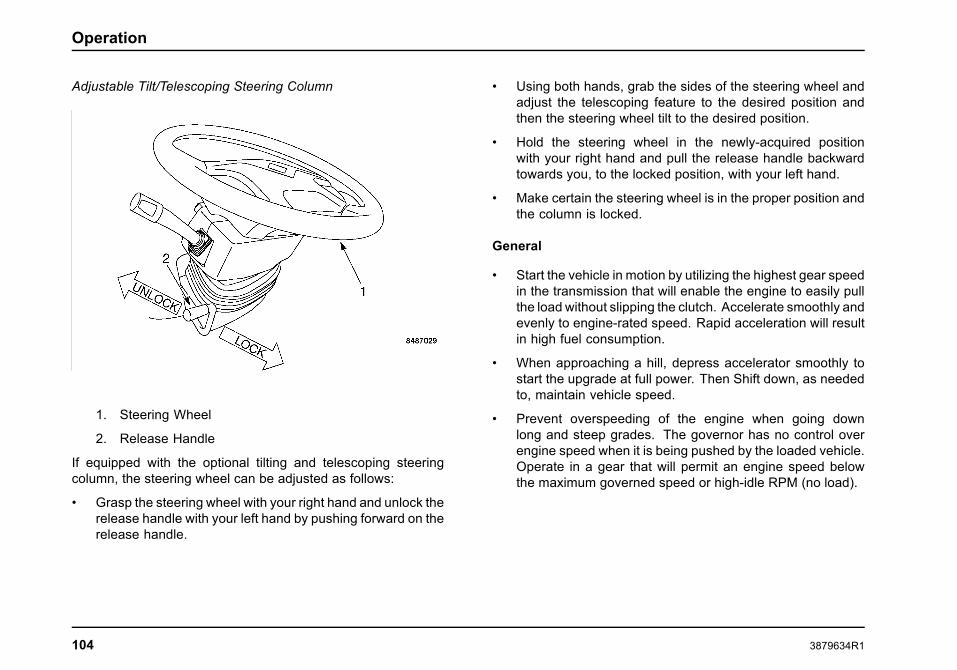
Operation
Adjustable Tilt/Telescoping Steering Column
1. Steering Wheel
2. Release Handle
If equipped with the optional tilting and telescoping steeringcolumn, the steering wheel can be adjusted as follows:
• Grasp the steering wheel with your right hand and unlock therelease handle with your left hand by pushing forward on therelease handle.
• Using both hands, grab the sides of the steering wheel andadjust the telescoping feature to the desired position andthen the steering wheel tilt to the desired position.
• Hold the steering wheel in the newly-acquired positionwith your right hand and pull the release handle backwardtowards you, to the locked position, with your left hand.
• Make certain the steering wheel is in the proper position andthe column is locked.
General
• Start the vehicle in motion by utilizing the highest gear speedin the transmission that will enable the engine to easily pullthe load without slipping the clutch. Accelerate smoothly andevenly to engine-rated speed. Rapid acceleration will resultin high fuel consumption.
• When approaching a hill, depress accelerator smoothly tostart the upgrade at full power. Then Shift down, as neededto, maintain vehicle speed.
• Prevent overspeeding of the engine when going downlong and steep grades. The governor has no control overengine speed when it is being pushed by the loaded vehicle.Operate in a gear that will permit an engine speed belowthe maximum governed speed or high-idle RPM (no load).
104 3879634R1

Operation
Electrical
WARNING
This vehicle may be equipped from the factorywith electrical switches intended to operateequipment that was installed by a truckequipment manufacturer (TEM). Instructions,Cautions, and Warnings for this additionalequipment will NOT be found in this manual.Read and understand the appropriate manualfor the specific equipment in question beforeoperating. Failure to observe this warning maycause property damage, personal injury, or death.
NOTE: This vehicle may be equipped with electronic, applicationspecific options not described in this Operator’s Manual. Manyof these features are supplied with rocker switches that havecustom labels applied. The presence of these options as factoryinstalled can be verified from the Line Set Ticket included withthe vehicle. A truck equipment manufacturer (TEM), however,may have installed some of these options after production. Inthat case, they will not appear on the Line Set Ticket. If installedby a TEM, you should receive an operating guide and/or trainingfor the specific functions provided.
NOTE: Familiarize yourself with all of the switches thatcontrol chassis, engine, and body equipment and seekadequate training on the function of all features beforeoperating this vehicle. Additional detailed information onthese optional features may be found in the CT-471 BodyBuilder Manual, Electrical System Component Section, andthe Body Builder Electrical Guide, both available through theinternationaltrucks.com Web site (Body Builder option, underCustomer Support menu).
Electrical System
The Electrical System provides a means to distribute theelectrical power and provide the driver with controls andindications of vehicle performance. This system usesmultiplexing for connecting to major functional areas of thetruck with much less wiring. The system provides interfacesto a majority of vehicle switches and sensors. The systemalso communicates with the standard and optional systemcontrollers and modules in the vehicle. These include: theBody Controller (BC), the Electronic Gauge Cluster (EGC),the engine Electronic Control Module (ECM), a TransmissionControl Module (TCM), the ABS Electronic Control Unit (ECU),panel-mounted switches, and door pods.
3879634R1 105

Operation
Alternator
CAUTION
Before connecting a fast charger or boosterbattery, or installing a new battery, make surethat the ground polarities of the fast charger,booster battery, or alternator (when installing abattery) are matched to the ground polarity of thevehicle battery. Improper usage of fast charger,hook-up of booster battery, or installing batterycan cause damage to the electrical system orto the alternator. Do not attempt to polarize thealternator.
Many alternators used in International® vehicles are of theself-energizing type. Some engines may need to be brieflyrevved after starting to turn on the alternator. The alternator willthen charge at idle. If the vehicle is to be warmed up prior tobeginning operation, the operator should observe the voltmeteror ammeter for charging indication before leaving the vehicle.
Ammeter
The optional ammeter indicates the rate of charge of electriccurrent supplied by the alternator to the battery, or the rate ofdischarge from the battery. At low engine speeds, the ammeterindicator may show a negative or discharge reading. When thebattery is fully charged, a very slight charge is indicated duringnormal vehicle operation.
Battery
WARNING
Keep lighted tobacco, flames, sparks or otherignition sources away from the batteries. Gasfrom the battery cells is flammable and canignite and/or explode. This is particularly truewhen jumper cables are being used. Batteryfires or explosions could cause personal injury,including severe injury to the face, eyes, limbsand body.
In addition, inhaling the hydrogen gas producedby the normal operation of the battery couldresult in partial or permanent damage to therespiratory system which may result in death.
WARNING
Whenever disconnecting battery terminals,always disconnect ground terminal first. Whenreconnecting, always connect ground terminallast. Failure to follow this procedure could resultin a short-to-ground and cause property damage,personal injury, or death.
Always wear eye protection when workingaround batteries. Do not attempt to jump-start avehicle with a frozen battery because the batterymay rupture or explode. If a frozen battery issuspected, thaw out battery and recharge.
106 3879634R1

Operation
WARNING
Do not check battery condition by shorting(flashing) across terminals. Failure to observethis warning could result in personal injuryand/or damage to the vehicle.
When working around the terminals and battery, use extra careto avoid shorting. A good practice is to use insulated pliers andscrewdrivers.
Battery Disconnect Switch
This optional switch is used to prevent the batteries fromdischarging. When a vehicle is not going to be operated forseveral days, this switch can be used to shut off the systemso the electrical components on the vehicle, if left on, will notdischarge the batteries.
These features have options that provide a key or leveroperated battery disconnect switch, which may be cab mountedor mounted on the battery box. There are also options thatcompletely disconnect the batteries or disconnect everythingexcept the charging circuits.
Circuit Breakers, Fuses, and Fusible Links
WARNING
Electrical circuits are designed with a particularwire gauge to meet the fuse and circuit breakercurrent rating. Do not increase size of fuse orcircuit breaker or change type of breaker suppliedwith your truck. To do so could cause wiring tooverheat and possibly burn, resulting in a fire,which could cause property damage, personalinjury, or death.
Electrical circuits are protected either by the body controller,circuit breakers, fuses, or fusible links. For the size and locationof circuit breakers, fuses, and fusible links, please refer tothe Maintenance Intervals And Specification section of thismanual.
Fusible links consist of a length of lighter gauge wire in a circuit.In case of a short or overload, the fusible link opens (burns out) toprotect the remainder of the circuit. Repair consists of splicingin a new fusible link with the same gauge wire as the openedfusible link.
Circuit breakers interrupt the circuit when an overload or shortoccurs. Manual circuit breakers (Type III) can be reset bydepressing the reset button on the breaker. Headlamp andwiper circuits are protected by the Body Controller Virtual Fusingsystem. Type II circuit breakers will reset if the short is removedfrom the circuit.
The various electrical units in the cab and engine compartmentsare protected by either fuses or circuit breakers. The power
3879634R1 107

Operation
distribution center is located behind a hand-removable cover onthe instrument panel on the passenger side of the vehicle.
Engine
The engine for this vehicle is an electronically controlled dieselengine. A separate electronic control module (ECM) monitorsand controls all engine functions. This ECM also communicateswith the body electrical system, which will generate or activatethe necessary indicators to alert the driver of out-of-rangeoperating conditions.
For complete information on the engine in this vehicle andits optional features, refer to the Engine Operation andMaintenance Manual supplied with this vehicle.
NOTE: For information pertaining to fuel and requirements referto the Engine Operation and Maintenance Manual provided withthe vehicle.
Charge Air Cooler
All MaxxForce® engines are equipped with a charge air coolingsystem. The function of the charge air cooler is to cool the hotcompressed air before it enters the engine’s intake manifold.This system uses ambient air as the cooling medium by allowingthe intake air to pass through a network of heat exchangingfins and tubes prior to entering the combustion chamber. Theresulting cooler intake air is denser than uncooled air and willallow additional fuel to be injected for greater power while helpingto reduce emissions.
Engine Brake, Retarder (Optional)
WARNING
Do not use the vehicle retarder, engine brakeon slippery road surfaces. Doing so may causewheel slippage and/or loss of vehicle control,which could result in property damage, personalinjury, or death.
WARNING
Before operating the Engine brake feature, studythe following descriptions and instructions aswell as the engine Operator’s manual. Failure todo so could result in property damage, personalinjury, or death.
NOTE: The engine brake should never be considered asubstitute for the vehicle service brakes. The service brakesshould always be viewed as the primary vehicle slowing system.Service brakes are always used to bring vehicle to a completestop.
Engine braking features are used for traffic conditions thatrequire frequent use of the service brake and thereforeshortening brake lining life. The features also allow the driverto slow the vehicle down or maintain a constant speed on steeproad grades that would otherwise result in prolonged use of theservice brake that could cause brake fade.
The optional braking features are controlled by the driver usingthe ENGINE BRAKE ON/OFF switch, and ENGINE BRAKE
108 3879634R1

Operation
SELECTOR 1/2/3 switches that are located in the centercontrol switch panel. The following paragraphs provide a briefdescription of these optional braking features.
Engine Brake System Operation
Vehicles, with MaxxForce® DT, 9, or 10 engines, utilize either theoptional Diamond Logic® Engine Brake for additional braking invarious operating conditions.The optional Diamond Logic® EngineBrake is a compression style brake thatutilizes the injection control system pressureand the closed vanes of the turbocharger formaximum braking power. The Engine brakeis controlled by the switch panel switches:ENGINE BRAKE ON/OFF, and ENGINE BRAKE SELECTOR1/2/3. To activate the engine brake, place the ENGINE BRAKEON/OFF to the ON position (the switch indicator will turn on).The ENGINE BRAKE SELECTOR 1/2/3 switch is used to adjustthe amount of braking applied.
NOTE: The ECM will not allow the Diamond Logic® EngineBrake to operate until the engine oil has reached the acceptableminimum temperature, therefore, do not attempt to activatethe engine brake until the engine has reached full operatingtemperature.
NOTE: The engine brake feature will automaticallydeactivate if either the accelerator or the clutch ispushed, or when the engine speed falls to 1000 RPM.
Operational Modes
The engine brake will operate in one of these two modes.Changes must be reprogrammed, in the engine controller, byan authorized International dealer.Coast Mode. In the coast mode, with the brake enabled, thebrake will activate when the driver hits the service brake (at orabove 1200 RPM). The brake will deactivate if the driver releasesthe brake pedal, or if the engine speed drops below 1200 RPM.
Latched Mode. In the latched mode, with the brake enabled,the braking will activate when the driver’s foot is lifted from theaccelerator pedal (at or above 1200 RPM). If, however, thecruise ON/OFF switch is in the ON position (with or withouta cruise set speed), engine brake function defaults to CoastMode and braking is activated by pressing the brake pedal anddeactivated by releasing the brake pedal.
MaxxForce® 11 and 13 Engine Brake With EatonAutoShift®/UltraShift® Transmissions Special DriverInstructions
Low or manual transmission mode can be used to maximizeengine brake performance.
• Keep engine speed as close to 2250 rpm as possible.
• Maintain brake pedal application until any desireddownshifts are completed. Failure to do so may causemissed shifts.
3879634R1 109

Operation
• The gear display on the shift selector will stop blinkingwhen the downshift is completed, and the driver will noticeresumption of engine braking as an indication that the shiftis completed.
When the transmission is in manual mode, engine protectionupshifts are disabled. This could result in an undesirable engineoverspeed condition. It is the operator’s responsibility to preventmechanical damage to the truck. Under these conditions, useservice brakes and select the appropriate gear, as required, tokeep the engine rpm within operating limits.
Automatic Transmission Operation
With the Allison transmission, when the engine brake isactivated, the transmission is programmed to perform shiftschedules that maximize braking effects.
The Allison transmission control module is programmed with apre-selected 4th gear as a default. This means that when thedriver selects “D” or Drive, the engine brake will operate downto 4th gear (at or above 1,200 RPM). If the driver manuallyselects 3rd or 2nd gear, the engine brake will operate down tothe manually selected gear (at or above 1200 RPM).
NOTE: Manually selecting 3rd or 2nd gear during braking withno load or during slippery driving conditions could result in aloss of traction, as indicated in the above warning. Manuallyselecting 3rd gear or 2nd gear will not cause damage to theengine or transmission. The manually selected gear is only fordriver intent. The transmission will only downshift according tothe pre-programmed shift schedules.
The engine brakes will deactivate when the transmission shiftsfrom converter lock-up to normal torque converter operation.
ABS Operation
When an ABS event occurs, the engine brake will turn OFF andwill automatically be turned back ON when the ABS conditionsare no longer present.
MaxxForce® Engine Features
The MaxxForce® engines are electronically controlled dieselengines. The engine Electronic Control Module (ECM) monitorsand controls the injection process and other engine functions.The ECM also communicates with the Body Controller (BC)and alerts it to out-of-range operating conditions. The BCin turn, generates engine function indicators and warningindicators. Since many of the engine performance features areowner selectable and electronically programmable, some of theoperating parameters will vary from vehicle to vehicle. Someof these standard and optional monitored engine operatingfunctions and warning indicators include:
Some standard features:
• Engine Warm-Up Control - (ECM) adjust injector operationas required.
• Cold Ambient Protection (CAP) - to aid engine warm up andmaintain engine temperature.
• Cruise Control - provides vehicle speed control.
110 3879634R1

Operation
Some Optional Features:
• Engine Warning System - this system illuminates the Red“Engine” indicator and actuates a beeper when warningthresholds for coolant temperature, engine coolant level,and/or low engine oil pressure are exceeded.
• Engine Shutdown System - this system shuts downthe engine after 30 seconds of operation beyond criticalthreshold values for coolant temperature and/or oil pressure.
• Throttle Control for PTO Operation.
• Road Speed Limiting/Governor - programmable maximumspeed.
• Idle Shutdown Timer - shuts down engine after 5 minutes ofidle time.
Certified Clean Idle
MaxxForce® 11 and 13 engines have been designed to meetthe new California Air Resources Board (CARB) idle reductionstandards by generating less than 30-g/hr. NOx emissions whenidling. These engines can be identified by the Certified CleanIdle decal located on the left side of the hood or driver door.
Self Diagnostics
All MaxxForce® Engine operating parameter Warning Indicatorsare located on the instrument panel gauge cluster. When theignition switch is turned ON, the Engine Warning Indicators areilluminated and remain on while the ECM runs normal start-uptests, then goes OFF. If warning indicator stays on or comes on
while operating the vehicle, it is an indication that the vehicleneeds service. When the warning indicator is illuminated, aDiagnostic Trouble Code (DTC) will be generated. Take thevehicle to a service center as soon as possible as some optionalfeatures and or engine power may be lost while the indicator islit.
Engine Warning/Protection System (EWPS)
The engine provides three distinct levels of protection:
• Standard Engine Warning System 2-Way
• Optional Engine Warning System 3-Way (08WWJ)
• Optional Engine Protection System 3-Way (08WPP)
Standard Engine Warning System 2-Way
The ECM monitors engine operating conditions for excessiveengine speed, low oil pressure, and coolant temperature. Ifthese conditions occur, a fault code will be set, but the YellowEngine Warning indicator or the Red Engine Warning Indicatorare not turned ON. Standard instrumentation includes an oilpressure and engine coolant temperature gauge.
CAUTION
Allowing water to stay in the fuel systemcould result in extensive damage to the fuelinjection system. Refer to the appropriate EngineOperation and Maintenance Manual for moreinformation.
3879634R1 111

Operation
NOTE: If the Oil/Water Warning Indicator comes ON, bring thevehicle to a safe stop and shut the engine OFF before shutdownoccurs.
Optional Coolant Warning Level System – 3 Way (08WWJ)
This option provides a warning if the coolant is below the safeoperating level.
NOTE: If the RedEngine Warning Indicator comes ON, bring thevehicle to a safe stop and shut the engine OFF.
Optional Engine Protection System – 3 Way (08WPP)
WARNING
In the event engine shutdown occurs, makecertain that vehicle is safely off the roadway,the 4-way emergency flashers are on, and thewarning devices are properly placed. Failure toremove vehicle from roadway could result in anaccident, personal injury or death.
This system includes the 3-way engine warning system. Inaddition, if engine oil pressure, excessive engine speed, enginecoolant temperature or engine coolant level conditions exceedthe warning limits, the appropriate fault codes are set and theRed Engine Warning Indicator is turned ON. If the engine oilpressure, engine coolant temperature or engine coolant levelconditions exceed the preset critical limit, the engine is shutdown. After an automatic shutdown, the engine can be restarted
and will operate in a de-rated mode for an additional 30 secondsif the conditions causing the shutdown are still present (SeeAutomatic Engine Shut-Down and Restarting procedure).
Air Compressor Cycling
The MaxxForce® 11 and 13 Liter engines can be equipped withone of two different types of air compressor and may have oneor two cylinders.
• Direct Line Unloaded (DLU) Air Compressor: Thisconstantly engaged air compressor works in conjunctionwith the air governor and air dryer to pump compressed airto the air dryer and air tanks. When additional compressedair is not needed, air is pumped to the atmosphere via themuffler equipped, frame- mounted unloader valve. Thissystem provides relatively lower air compressor cylindertemperatures verses head-unloaded compressors duringthe unloaded cycle. It is normal to hear a small amount ofcompressor-created sound during the unloaded cycle.
• Head Unloaded Air Compressor: This single cylinder,constantly engaged air compressor works in conjunctionwith the air governor and air dryer to pump compressed airto the air dryer and air tanks. When additional compressedair is not needed air is shut off from the air compressordischarge line and confined to the air compressor cylinderand its head. This system provides relatively higher cylindertemperatures verses head-unloaded compressors duringthe unloaded cycle, but does not require the plumbing andcomplexity of the DLU compressor. It is relatively quieterduring the unloaded cycle than the DLU.
112 3879634R1

Operation
• Clutched Air Compressor: This high-capacity, twocylinder, air compressor is periodically engaged by usingan on-off clutch. It works in conjunction with air governorand air dryer to pump air to the air dryer and air tanks.When additional compressed air is not needed, the clutchis disengaged, compressor speed goes to zero, and allair pumping ceases. This system provides relatively lowcylinder temperatures and sound verses other compressorsduring the unloaded cycle. It is used to promote maximumfuel economy by eliminating pumping energy loss duringthe unloaded cycle.
As the compressor reaches approximately 120 psi (827 kPa),the air governor will, through various methods stop the aircompressor from pumping pressurized air to the air system.When the air pressure reaches approximately 105 psi (724kPa), the governor signals the air compressor to resumepumping pressurized air to the air system. During normalengine operation, this cycle will be evident by the fluctuation ofthe primary air tank pressure gauge.
Cooling System
WARNING
To prevent personal injury or death from hotcoolant or steam, use only the followingprocedure to remove the pressure cap fromthe deaeration tank. Allow the engine to coolfirst. Wrap a thick, heavy cloth around thecap. Depending on the type of cap, push down,loosen cap slowly to its first notch position, orunscrew cap slowly; then pause a moment toallow pressure to release through the overflowtube. After the pressure has been released, thepressure cap may be removed.
WARNING
Exercise care when working on vehicles withrunning engines that are equipped with anautomatic fan clutch. The fan engages whenengine coolant reaches a predeterminedtemperature or the refrigerant pressure (ifequipped with air conditioning) reaches apredetermined setting. The fan will start withno advance warning. Failure to observe theseprecautions could result in vehicle damage,personal injury, or death.
3879634R1 113

Operation
WARNING
Do not exceed the pressure rating on thedeaeration tank cap. Ensure that the pressurerating of the deaeration tank cap matches thatlisted on the side of the tank, or the tank mayburst, causing property damage, personal injury,or death.
CAUTION
If the coolant should get extremely low andthe engine very hot, let the engine cool forapproximately 15 minutes before adding coolant;then, with the engine running, add coolant slowly.Adding cold coolant to a hot engine may crackthe cylinder head or cylinder block. Never usewater alone.
Antifreeze
The cooling system of your new vehicle is filled at the factorywith either a Type II Fully-Formulated (purple) or Type III ELC -Extended Life Coolant (red). The type of coolant depends uponthe engine manufacturer and the preference of the purchaser ifoptional coolants are allowed.
The Type II coolant must meet Type ll specs, such as theFleetrite® Premium 50/50 with SCA (P/N ZJJSCA5550). TheType III coolant must meet Type IlI specs, such as the ShellRotella® ELC - Extended Life Coolant (P/N 94042). Refer tothe label on the deaeration tank to determine the coolant type.
Consult the Engine Operation and Maintenance Manual forcoolant service life details.
For vehicles with MaxxForce® 11 and 13 engines, the coolingsystem of your new vehicle will be filled at the factory withnitrite-free Shell Rotella® Ultra ELC (YELLOW) coolant.International Truck recommends using only the approvedcoolant with the 2010 cooling packages, and will not warrantthese cooling systems that have not utilized the recommendedcoolant.
The label on the deaeration tank provides additionalcoolant/antifreeze information. Consult the Engine Operationand Maintenance Manual for coolant service life details.
Engine Oil
For maximum fuel economy and engine protection, keep oillevel between the ADD and FULL marks on the dipstick. Neveroperate an engine with oil level above the FULL mark or belowthe ADD mark.
When checking the oil level, the dipstick must be withdrawn andwiped clean, then inserted all the way in and again withdrawn fora true check.
To obtain an accurate engine oil level reading the vehicle mustbe parked on a level surface with the engine off for at least fiveminutes before checking the oil level. This will ensure the oilis level in the oil pan, and the circulated oil has had a chance toreturn to the pan. It is not necessary for the oil to be hot to obtainan accurate reading.
Use only recommended viscosity engine oil. Refer to the EngineOperation and Maintenance Manual for engine oil specifications.
114 3879634R1

Operation
The lubricating oil in a diesel engine becomes dark in colorafter short periods of engine operation. This discoloration is notharmful to engine parts as long as the oil and oil filter elementchanges are performed at recommended intervals.
Engine Performance Problems
• Low engine power can be the result of a plugged fuel filter.Fuel filters can plug prematurely due to the use of fuel thatis contaminated with a high amount of sediment, microbialgrowth, or water. Fuel that has been stored for longerperiods of time may also reduce engine performance.
• Failure to maintain the vehicle as required in theMaintenance Instructions and Maintenance Intervalsand Specifications sections of this manual, as well as anyseparately available Engine Operation and MaintenanceManual, can cause engine performance problems.
Too low of cetane number could cause hard starting andslower warmup and could increase engine noise and exhaustemissions.
Fuel
Ultra Low Sulfur Diesel Fuel Requirements
Ultra Low Sulfur Diesel (ULSD) fuel is required for all on-highwaydiesel engines used with advanced after-treatment systems(Diesel Particulate Filters – DPF). For complete details on fuelrequirements, see the Engine Operation and MaintenanceManual supplied with the vehicle.
Unacceptable Fuel Blends
Biodiesel blends having more than 5 percent pure biodiesel arenot within ASTM D975 diesel specifications.
To determine acceptable biodiesel and biodiesel blends, refer tothe Engine Operator and Maintenance Manual for the applicableengine.
Hazards of Diesel Fuel/Gasoline Blends
WARNING
Never add gasoline, gasohol and/or alcohol todiesel fuel. This mixture creates an extremefire and explosion hazard which could result inproperty damage, personal injury, or death.
Blending of gasoline and/or alcohol with diesel fuel is notrecommended due to the hazards of fire/explosion and thedetrimental effects on engine performance.
As little as two percent volume gasoline mixed with diesel fuelwill create a flammable/explosive mixture in the fuel tank vaporspace, which will pose an extreme fire/explosion hazard duringrefueling or engine operation.
Additional Unsafe Practices
CAUTION
To prevent engine damage, do not mix propanewith diesel fuel. Warranty claims will not behonored against engines that have used propane.
3879634R1 115

Operation
CAUTION
To prevent engine damage, do not mix engineoil with diesel fuel. Warranty claims will not behonored against engines that have used fuelmixed with oil.
Fuel and Lubricant Additives
International trucks are designed and built to operatesatisfactorily on fuels and lubricants of good quality marketedby the petroleum industry. Use of any supplementary fuel orlubricant additives is not recommended. Malfunctions attributedto the use of such additives or failure to follow recommendedfuel or lubricant recommendations may not be covered by anyapplicable warranty.
Fueling Procedures
NOTE: If your vehicle is equipped with dual fuel tanks, be sureto read and understand the following information before refuelingthe vehicle.
A dual tank system contains a primary and a secondary fuel tank.
With dual fuel tanks, the vehicle will be equipped with a fueltransfer pump system that will pump fuel from the secondary(reserve) fuel tank and send it to the primary (draw) fuel tank.The draw fuel tank must have fuel in it at all times, otherwise thevehicle may stall and may be difficult to restart (the fuel gaugereads the fuel level only from the draw fuel tank).
Therefore, when refueling, be sure that both tanks are filledcompletely, as it is sometimes difficult to determine which tankis the draw tank and which is the reserve tank.
Fueling Precautions
Federal Motor Carrier Safety Regulations require the driveror any employee of a motor carrier to observe the followingrequirements:
1. Do not fuel a motor vehicle with the engine running,except when it is necessary to run the engine to fuel thevehicle.
2. Do not smoke or expose any open flame in the vicinityof a vehicle being fueled.
3. Do not fuel a motor vehicle unless the nozzle of the fuelhose is continuously in contact with the intake pipe ofthe fuel tank.
4. Do not permit any other person to engage in suchactivities as would be likely to result in fire or explosion.
Reserve Fuel
No extra supply of fuel for the propulsion of the vehicle or for theoperation of accessories shall be carried on any motor vehicle,except in a properly mounted fuel tank or tanks.
116 3879634R1

Operation
Exhaust Diesel Particulate Filter Regeneration
This vehicle is equipped with a Diesel Particulate Filter(DPF) to meet 2010 emissions requirements. The DPF trapsexhaust particulate matter generated by normal engine usage.Periodically, the engine control system will perform a “cleaning”of the filter, known as Normal Regeneration. This process istransparent to the operator and occurs during normal vehicleoperation.
In some cases the engine control system is unable to managesoot levels in the DPF through Normal Regeneration. Whenthis occurs the DPF indicator will illuminate solid YELLOW onthe instrument panel gauge cluster advising that action must betaken. At this time the vehicle should then be driven at highwayspeeds, or pulled over to perform a Parked Regeneration (SeeParked Regeneration Procedure). If no action is taken theDPF indicator will begin to flash indicating that the filter is full.The vehicle should then be pulled safely off the roadway anda Parked Regeneration should be performed. If the vehicle isdriven beyond the initial two warning stages, a loss of engineperformance (de-rate) will occur. Ignoring the need for a ParkedRegeneration, when required, can result in a warning forexcessive exhaust temperatures, and a requirement to shut theengine off and not restart it until the DPF has been serviced bya technician. It is important to perform a Parked Regenerationwhen required. Failure to do so could be mission disabling andresult in the vehicle being towed.
See the following information for a detailed explanation of DPFindicators and the corresponding procedures that must befollowed.
WARNING
Failure to perform a Parked Regeneration whenexhaust filter indicator is ON will cause the engineto lose power and eventually shutdown.
When performing Parked Regeneration, makecertain vehicle is safely off of the roadwayand exhaust pipe is away from people, or anyflammable materials or structures.
Failure to follow these instructions may result ina loss of engine power, vehicle speed, increasedexhaust temperatures, and may cause anaccident or fire resulting in property damage,personal injury, or death.
There will be three levels of indication that the vehicle’s exhaustfilter is accumulating soot and needs to be cleaned, each withan increasing urgency for action.
NOTE: A Level 1 indication may disappear or a Level 2 mayrevert to a Level 1, if the vehicle is driven on highway athighway speeds for an extended period. This process of autoregeneration of the exhaust filter is activated when the engineload is increased as a result of highway driving at highwayspeeds. If the DPF indicator does not reduce in level ordisappear, a Parked Regeneration must be performed.
NOTE: The following table is a typical representation of 2010DPF emissions procedures (See visor for vehicle federalemissions label).
3879634R1 117

Operation
2010 Federal Emissions Label
Level Indication Audible Alarm LCD Text Message VehicleConditions/Operation Action Required
1
(Solid)
None
Scrolls betweenSee Visor for infoand Parked RegenRequired.
Exhaust filterregeneration required.
Drive on highway at highway speeds or start ParkedRegeneration to prevent loss of power.
2
(Flashing)
None
Scrolls betweenSee Visor for infoand Parked RegenRequired.
Exhaust filter is full.Pull vehicle safely off roadway and start ParkedRegeneration to prevent loss of engine power.
3
(Flashing)
An alarm will beepcontinuously whileignition is on.
Scrolls betweenSee Visor for infoand Parked RegenRequired.
Exhaust filter is full.Engine performance isLIMITED.
WARNING
Pull vehicle safely off roadway andstart Parked Regeneration to preventengine stopping.
Exhaust System Temperature is HOT
WARNING
Exhaust components are operating under normal conditions and exhaust gases are at extremely high temperatures.When stationary, keep away from people and flammable materials, vapors, or structures or STOP ENGINE
A serious problem has occurred. Engine may SHUTDOWN soon. Pull vehicle safely of roadway, turn on flashers, set parking brake,place warning devices, and STOP ENGINE. Seek service immediately.
118 3879634R1

Operation
Parked Regeneration Procedure
Perform the following steps to initiate Parked Regeneration(cleaning) of the exhaust filter:
1. Park the vehicle safely off the roadway and away fromflammable materials.
2. Before initiating parked regeneration (using the ON/PARKDREGEN switch), the following conditions must be in place:
a. Parking brake must be set
b. DPF indicator illuminated (Solid or Flashing).
c. Transmission must be in Neutral (N) or Park (P), ifavailable
d. Accelerator, foot brake and clutch (if present) pedalsmust not be depressed,
e. Engine temperature must be at a sufficient level to allowregeneration.
With some engines, this may be as high as 170° F (76.6°C).
NOTE: The engine coolant temperature must be above 170°F (76.6° C) before the parked regeneration procedure can beperformed. If the engine coolant temperature is too low, theparked regeneration procedure will not activate.
3. Press the ON position of the ON/PARKD REGEN switch toinitiate the regeneration cycle.
The engine speed will automatically ramp up to a presetRPM, PARKD REGEN ACTIVE will be displayed in the
information display, and the switch indicator will illuminatewhen the cycle is started. If the indicator is blinking, checkto be sure that all conditions in step 2 have been met. Oncestarted, the regeneration cycle will last approximately 30minutes.
NOTE: If any of the above conditions are altered during theParked Regeneration process, regeneration will be halted, andmust be restarted.4. When the regeneration cycle is complete, the
switch indicator will go off, the engine rpm willreturn to normal idle and all exhaust filter warningindicators will be off. The vehicle may now bedriven normally.
NOTE: In the event of an emergency situation where the vehiclemust be moved after beginning Parked Regeneration, pressPARKD REGEN position of the ON/PARKD REGEN switch tocancel Parked Regeneration.
Regeneration Inhibit Switch
The optional Regeneration Inhibit switch is usedto prevent the normal regeneration or parkedregeneration processes.
NOTE: There are two versions of the regenerationinhibit switch: the two-position and the three-positionswitch. Therefore, it’s necessary to verify which version isinstalled in this vehicle. Both versions have the same switchlabels.
3879634R1 119
Operation
Two-Position Regeneration Inhibit Switch
With the optional two-position switch, pressing the ON positionof the ON/INHIBT REGEN switch will inhibit both normal andparked regeneration. Regeneration will be inhibited (latched)when in this position and the switch indicator is turned on.
Three-Position Regeneration Inhibit Switch
The optional three-position switch is a center stable momentaryswitch. Pressing the ON position inhibits normal regenerationwhile the engine is running and is reset when the ignition switchis turned off. The Inhibit function is cancelled when the lowerposition is pressed, or parked regeneration is initiated (PARKDREGEN switch is turned to the ON position).
The switch indicator will be turned on whenever regenerationinhibit is enabled.
Transmission
Manual Transmissions
Vehicles with manual transmissions have a clutch pedal that isused to engage or disengage the clutch or for connecting ordisconnecting the engine from the transmission and rear wheels.With the clutch pedal released (extended), the clutch is engaged,driving the transmission and rear wheels. Depressing the clutchpedal releases the clutch, permitting transmission gear changes.
Clutches will last many thousands of miles if properly used andmaintained. EXCESS HEAT IS A CLUTCH’S WORST ENEMY!Almost every early clutch failure can be traced to excessivefriction heat. Do not ride or slip the clutch. Once a clutch is
fully engaged, there is no heat generated and little or no wear.However, during the brief period when the clutch is picking upthe load, considerable heat is generated. By riding or slippingthe clutch, the period of partial engagement is lengthened,causing unnecessary heat and wear.
Engaging the Clutch
Always start in the proper gear: An empty vehicle can bestarted in a higher gear than a fully loaded one. But starting in agear too high for the load can cause too much clutch slippage,generating excessive heat and unnecessary wear. A gear thatwill start the vehicle moving with the engine at idle speed isusually correct. If the engine must be revved up to preventstalling, the gear selection is too high. As the clutch pedal isreleased and the clutch begins to engage, the engine speed willdrop slightly. When this happens, increase the engine speedand fully engage the clutch. Increasing the engine speed beforefully engaging the clutch can damage the clutch and drive train.
Do not shift until vehicle has reached proper speed.Upshifting before the vehicle has reached the right speed isalmost as bad as starting off in too high a gear. When thedifference between the vehicle speed and the engine speed istoo great, the clutch is forced to slip. The result is extra heatand wear.
Never hold a vehicle on a hill with the clutch. To hold on a hillwith the clutch requires that the clutch be purposely slipped. Bydoing this, enough heat can be generated to burn up the clutch.
Never coast with the clutch disengaged. This can causeclutch failure by the very high RPM encountered when coastingin gear with the clutch released. In this situation, the rear wheels
120 3879634R1

Operation
are driving the disc through the multiplication of the rear axle andtransmission ratios. This can result in over 10,000 RPM, whichis beyond the burst strength of the facing material. Something assimple as coasting down an unloading ramp can burst a drivendisc.
Never engage the clutch while coasting. Reengaging aclutch after coasting causes tremendous shock to the clutchand the whole drivetrain. It can result in internal engine damageand/or clutch and flywheel failure. Always report unusual clutchoperation promptly. Proper maintenance, performed on time,will greatly extend the life of the clutch. The driver should reportany change in free-pedal (free-travel), slippage, or any strangefeel to the clutch operation.
Helpful Hints to Operate Vehicles with Ceramic ClutchFacings
1. Driver must start vehicle in first gear.
2. While operating a ceramic clutch, the driver has to engagethe clutch before giving the engine any fuel (at idle).
3. The driver should not try to slip the ceramic clutch by raisingengine RPMs and riding or feathering clutch pedal, since thevehicle will experience erratic engagement.
Erratic engagement can cause engine stalling and potentialserious damage to your vehicle’s drivetrain components (i.e.,clutch, transmission, driveshaft(s), rear axle).
Clutch Brake (Vehicles with Nonsynchronized Transmission) –Vehicle Not Moving
A clutch brake is used to stop transmission input shaft rotation sothat the initial first or reverse gear selection can be accomplished
when the vehicle is at a standstill and the engine running at idlespeed. Clutch brake application occurs in the last 1 inch (25mm)of pedal travel.
When using the clutch brake, fully depress the clutch pedal andshift the transmission into either first or reverse gear. If thetransmission does not go into first gear or reverse, toothbuttingmay be occurring. Slowly release the clutch pedal while applyinglight pressure on the shift lever until the transmission goes intogear. This will provide for a smooth shift into either a forward orreverse gear.
NOTE: After engagement of first gear, DO NOT use the clutchbrake for upshifting and downshifting. To do so will shorten theservice life of the clutch brake, and gear selection shift effortsmay be increased. Clutch brake application occurs in the last 1inch (25mm) of pedal travel.
Double Clutch Procedures, Nonsynchronized
In order to properly upshift or downshift be sure to do thefollowing:
• Depress the clutch pedal to disengage the clutch.
• Shift the transmission into neutral.
• Release the clutch pedal.
• If upshifting, wait until the engine speed matches thetransmission speed of the gear you desire to shift into.
• If downshifting, accelerate the engine until the engine speedmatches the input speed of the gear you desire to shift into.
3879634R1 121

Operation
• Depress the clutch pedal immediately and shift into thedesired gear.
• Release the clutch pedal to engage the clutch.
Clutch Precautions
Maintain specified clutch adjustment. Regularly inspect clutchcontrol linkage for tightness.
When adjustment of the clutch is necessary, it is extremelyimportant that the work be properly performed; otherwise, earlyfailure of the clutch will result and a costly clutch overhaulbecomes necessary.
To avoid needless delay and expense, allow only competent andexperienced mechanics to perform these operations.
Shifting with Synchronized Transmission
With the clutch released (pedal depressed), use second speedgear synchronizer to stop clutch disc rotation. This will allowsmooth engagement of first or reverse gear selection. In orderto complete gear engagement, it may be necessary to applylight pressure to the shift lever during initial engagement ofthe clutch. It takes one to two seconds to match gear speeds.
Steady pressure on shift lever will help the synchronizer performits job quicker. If the shift lever is forced into gear it is possible tooverride a blocker and defeat the purpose of the synchronizer,causing gear clash.
Shifting with Nonsynchronized Transmission
Refer to Clutch Brake (vehicles with nonsynchronizedtransmission) and Double Clutch Procedures in this section(above).
Operation of the Eaton AutoShift® Transmission and Shifter
WARNING
To prevent unexpected vehicle movement, holdthe brake pedal down while you move thegearshift from position to position. Hold downboth brake and clutch pedal while pushing the“R” or “D” button. If you do not hold the brakepedal down, your vehicle may move unexpectedlyand cause property damage, personal injury, ordeath.
122 3879634R1

Operation
1. Reverse Button
2. Neutral Button
3. Forward Gear Selector Button
4. Hold Button
5. Low Gear Button
6. Downshift Button
7. Upshift Button
8. Service Indicator
The Eaton AutoShift® is a partially automated transmissionthat automatically selects and engages the proper transmissiongears. Some vehicles are equipped with an optional clutchpedal that must be used when starting and stopping the vehicle.
To shift the Eaton® transmission into Reverse (R) or Drive (D),first place foot on the brake and optional clutch pedal. Whenin Drive (D), the transmission selects the starting gear andautomatically selects the proper gears for operating loads. Toselect a higher or lower gear, first press the Hold button and useeither the up arrow or down arrow shift buttons. If LO is selectedwhile the vehicle is stopped, the transmission will remain in LOgear until another gear is selected. If selected while in motion,the transmission will downshift when it is safe to do so. To placethe transmission in Neutral, press the (N) button.
Eaton UltraShift® Transmissions (Optional)
The optional Eaton UltraShift® transmission is an automatictransmission that can automatically select and engage theproper transmission gears. Vehicles equipped with thistransmission do not have a clutch pedal. For operatinginstructions, refer to the Transmission Manual.
Automatic Transmissions
Allison Transmissions
NOTE: For a complete description of the Allison AutomaticTransmissions, refer to the Allison Transmission Operator’sManual, supplied with this vehicle.
Allison Transmission with “P” – (Park) Park Pawl Mechanism or“PB” – Parking Brake Position
“P” – Park Pawl. A park pawl transmission effectively groundsthe output shaft, thereby preventing rotation of the driveline.If the vehicle is stationary, selecting the “P” (Park) position on
3879634R1 123

Operation
the shift selector places the transmission in “N” (Neutral) andengages the park pawl (always use with the Parking brake).
NOTE: If you attempt to engage “P” position while vehicle is inmotion (1 mph, 2 km/hr) or higher, the park pawl mechanism willratchet, and will not hold the vehicle.
“PB” – Parking Brake. For the transmissions with theAuto-Apply Parking Brake – “PB” position, selecting PB placesthe transmission in “N” (Neutral) and automatically engages theAir or Hydraulic parking brake.
CAUTION
Do not apply the parking brake with the vehiclein motion. Transmission and/or driveline damagecan result. In the event of a dynamic brake apply,recheck the torque of all brake mounting bolts toverify the integrity of the mount.
CAUTION
Sustained use of the parking brake with theengine running and the transmission in range cancause an overheating failure of the transmission.The instrument panel gauge cluster contains aParking Brake indicator that illuminates whenthe ignition switch is “ON”, the parking brakeis applied, and the transmission selector is inrange.
Parking The Vehicle
The following WARNINGS provide the methods of parking thevehicle using the various transmission shift selectors.
WARNING
To prevent sudden, unexpected vehiclemovement and property damage, personalinjury or death, always use the parking brakeIN ADDITION TO leaving the transmission ingear.
To prevent sudden, unexpected vehiclemovement and possible property damage,personal injury or death, perform the following:
• Bring the vehicle to a complete stop.
• Put transmission selector in “P” – Park Pawl, “PB” -Auto Apply Parking Brake , or N – Neutral.
For the park pawl (P – Park) transmissions, slowly liftfoot from brake pedal to engage transmission park pawlmechanism.
• Apply the parking brake (either lever or Parking Brakedash control) and ensure that it is holding properly. (Forthe “P” – Park Pawl transmissions, do not rely solelyupon the parking mechanism of the transmission).
124 3879634R1

Operation
WARNING
• For the Auto Apply Parking Brake (“PB” transmissions),make sure that the “PB” selection has applied theParking Brake (Parking Brake indicator should beturned On) by slowly releasing the service brake andverifying that the vehicle will not roll.
• Chock the wheels and take any other steps necessaryto keep the vehicle from moving.
• Turn off engine anytime you leave the vehicle. Neverleave the vehicle unattended with the engine running.
Preparing to Drive the Vehicle
WARNING
To prevent unexpected vehicle movement, holdthe brake pedal down while you move thegearshift from position to position. Failure tofollow this warning could result in propertydamage, personal injury, or death.
Read and perform the following steps for the particular vehicleParking brake whenever you prepare to drive away.
Parking Brake Interlock. To shift from P (Park) or PB (ParkingBrake), the shifter is equipped with a Parking brake Interlock.The ignition switch must be in the ON position and brake pedaldepressed before the gear selector can be moved from the P(Park) or PB (Parking Brake) position into the desired operationalposition.
Manual Parking Brake
After starting the engine, place foot firmly on brake pedal.
With foot still on brake pedal, select the desired transmissionoperating position.
With foot still on brake pedal, push manual Parking Brake leverdown to release, then lift foot from brake pedal to allow thevehicle to move.
Air Parking Brake or Power Parking Brake
After starting the engine, place foot firmly on brake pedal.
With foot still on brake pedal, push and hold shift selectorbutton and move selector to the desired transmission operatingposition.
With foot still on brake pedal, push in on Parking Brake controlknob to release parking brake (Air Brake) or push and releasethe control knob (Power Parking Brake), then lift foot from brakepedal to allow the vehicle to move.
Operation of the Allison Generation IV Gearshift Controls
WARNING
To prevent unexpected vehicle movement, holdthe brake pedal down while you move thegearshift from position to position. Failure tofollow this warning could result in propertydamage, personal injury, or death.
3879634R1 125

Operation
Both the T-Bar gearshift control and the Push-button gearshiftcontrol are available with the Allison automatic transmissions.They provide the same gear shift functions and control thetransmission in the same manner.
Allison Generation IV T-Bar Gearshift Control
1. Hold Override Button
2. Mode Indicator (Led)
3. Mode Button
4. Mode Id
5. Digital Display
6. Display Mode Diagnostic Button
When the vehicle is started, the transmissions are designedto operate in the standard performance mode. Pressing theMode button on the shift tower will switch the transmissionto Economy mode and illuminate Mode ON in the shift towerdisplay. Economy mode provides operation at a lower engineRPM while maintaining adequate performance.
If the engine speed is above idle when a gear is selected with theshift tower, the vehicle will not move. To move the vehicle, theshift tower must be moved to re-select a gear after the enginecomes down to idle.
For further information on the Allison transmission, refer tothe separate Allison vocational transmission model Operator’sManual.
Torque Lock
If the vehicle is parked on an incline and P (Park) is properlyengaged, the weight of the vehicle may generate an excessiveamount of torque on the park pawl in the transmission. In thissituation, it may be difficult to shift the transmission out of theP (Park) position. To drive the vehicle out of the torque lock,perform the following:
• Push the vehicle uphill a small amount to release thepressure on the park pawl and permit the shift out of P(Park). At this point, place foot on brake pedal.
• Hold foot on brake pedal while shifting the transmission outof P (Park).
• Release the parking brake.
126 3879634R1

Operation
Operation of the Allison Generation IV Push-button ShiftSelector
1. Digital Display
2. Mode Id
3. Mode Button
4. Range Selector Buttons
To shift the Allison transmission into Reverse (R) or Drive (D),first place foot on brake pedal. With foot on brake pedal, presseither R or D, release the Parking Brake, and then release thebrake pedal. When in Drive, to select a lower range press andrelease the down arrow button. To select a higher range, pressand release the up arrow button. To place the transmission inNeutral, press the (N) button.
3879634R1 127

Operation
Operation of the Column-Mounted Shifter
A Column-mounted shifter is used with some Allisontransmissions. The selected gear positions will be indicated, onthe instrument panel gauge cluster’s LCD display, by a dashdirectly under R, N, or gear number.
NOTE: When using the column-mounted shifter, while thetransmission is not in “P” – Park or “PB” – Parking Brake, theLCD display will indicate the selected gear at all times, even ifthe ignition switch is in the OFF position. With the ignition switchin the OFF position, when the transmission is shifted to the parkposition, the dash indicator shall disappear and the instrumentpanel gauge cluster will complete its shutdown.
To shift the transmission out of “P” – Park or “PB” – ParkingBrake, first read and then perform the following:
• First press foot on service brake pedal (see Park PositionInterlock section).
• For reverse, pull on shift control lever and move lever to“R” position (as indicated on LCD display), and then releasecolumn shift lever.
• Release the Parking Brake.
• Lift foot from service brake pedal to allow the vehicle to movebackward.
• To select a forward gear (while holding service brake pedaldown), pull on shift lever and move down thru “N” - Neutraland stop at “D” – Drive or any of the available gears asindicated on the LCD display.
• Release service brake pedal and allow vehicle to moveforward.
Main Transmission Controls
Main transmission, auxiliary transmission, transfer case, andpower take off control shift patterns can be found on a placardor decal on the driver’s visor door, on the instrument panel, oron the shift control itself. In certain cases, the shift pattern,for a component added by a Body Builder, will be in the BodyBuilder’s manual.
The main transmission control is used to select the various gearratios or speeds provided within the transmission.
Selection of the D (direct drive) gear does not change the gearratio provided by the main transmission but is used where thegear ratios in the main transmission are adequate to handle thevehicle operation.
128 3879634R1

Operation
Selection of the OD (overdrive) gear in the auxiliary transmissionpermits increased road speeds in the various transmissionratios.
A loaded vehicle should not be operated with the auxiliarytransmission in OD (overdrive) with the main transmission ineither of the two lowest speed gears. Doing so could causedamage to either the transmission or propeller shaft.
WARNING
Before backing up, check to see that area behindvehicle is clear of people, animals and objects.Use a spotter whenever possible and alwayskeep that person in sight. Failure to do so mayresult in property damage, personal injury, ordeath. If so desired, backup alarms are availablethrough your International dealer. However, theyare never a substitute for the above procedures.
Backup Alarm
An optional backup alarm feature is available and providesan audible warning signal whenever the vehicle is operated inreverse gear.
Auto Neutral
WARNING
When using the AUTO NEUTRAL feature, alwayshold the brake pedal down when releasingthe parking brake since the transmission willautomatically return to forward gear. Failure tofollow this warning could result in unexpectedvehicle movement causing property damage,personal injury, or death.
The optional Auto Neutral feature is available for applicationsinvolving frequent starts and stops that also require exiting thevehicle, such as refuse and concrete truck operations.
This feature is activated by placing the AUTO NEUTRALswitch in the UP position. When activated, the transmissionautomatically shifts to Neutral when the parking brake is applied,and the AUTO NEUTRAL indicator is illuminated. This featurealso causes the transmission to automatically shift into theforward gear when the parking brake is released.
The mode, that is installed in your vehicle, is identified by a decal,located near the shifter. There are TWO possible Auto Neutralmodes that are available for this vehicle. The two modes aredescribed below.
3879634R1 129

Operation
Temporary Neutral – 13AAZ. To activate this Auto Neutralfeature, perform the following:
1. To enable Auto Neutral , place the AUTO NEUTL/ONswitch in the ON position (the switch indicator will thenturn On).
2. When the Parking Brake is applied, the transmissionautomatically shifts to Neutral, and the AUTO NEUTRALindicator in the instrument panel gauge cluster will turnon.
3. The transmission shifter’s digital display shows ablinking “N”, indicating the transmission is in Neutral,and the instrument panel gauge cluster LCD display willindicate Neutral gear.When the parking brake is released, the transmissionwill go back to the gear originally selected, the shifter’sdigital display will show that gear, the LCD displaywill also indicate that gear, and the AUTO NEUTRALindicator will go off.Note: The Auto Neutral switch indicator will still beOn – indicating that the Auto Neutral function isstill enabled – and will remain on until the switch isplaced in the Off position.
4. Repeat these steps as long as the Auto Neutral modeis desired. To turn off the Auto Neutral mode, placethe AUTO NEUTL/ON switch to the off (AUTO NEUTL)position. This will turn Off the switch indicator.
Neutral gear Remains (Hard Neutral) – 13WUA. To activatethis Auto Neutral feature, perform the following:
1. To enable Auto Neutral feature , place the AUTONEUTL/ON switch in the ON position (the switchindicator will turn On).
2. When the Parking Brake is applied, the transmissionautomatically shifts to Neutral, and the AUTO NEUTRALindicator in the instrument panel gauge cluster will turnon.
130 3879634R1

Operation
3. The transmission shifter’s digital display will showa non-blinking “N”, indicating the transmission is inNeutral.
T-Bar shifter: when the parking brake is released, the shiftlever has to be moved to Neutral and then back to thedesired forward gear. The AUTO NEUTRAL indicator willgo off.
Pushbutton shifter: when the parking brake is released,press the shifter button for the desired transmissiongear.
Note: The Auto Neutral switch indicator will still be On –indicating that the Auto Neutral function is still enabled– and will remain on until the switch is placed in the Offposition. The AUTO NEUTRAL indicator will go off.
4. Repeat these steps as long as the Auto Neutral modeis desired. To turn off the Auto Neutral mode, placethe AUTO NEUTL/ON switch to the off (AUTO NEUTL)position. This will turn Off the switch indicator.
Power Take Off Control
If your vehicle is equipped with a power take off (PTO), refer tothe PTO equipment manufacturer’s instructions.
If vehicle is equipped with an Allison Automatic Transmission,refer to separate Allison Transmission Operator’s Manual.
Automatic Transmission Operating Temperature
For the Allison transmissions, the sump/fluid reservoirtemperatures (indicated by optional gauge or warning indicator)should not exceed 250°F (121°C). The converter temperature(indicated by optional gauge or warning indicator) should notexceed 300°F (149°C). For the transmissions with retarder, theconverter temperature (indicated by optional gauge or warningindicator) should not exceed 330°F (166°C).
3879634R1 131

Operation
Rear Drive Axles
Locking Differentials
WARNING
To prevent vehicle damage, personal injury, ordeath, pay strict attention to the following:
If your vehicle is equipped with any type oflocking or limited slip differential, power will betransmitted to the opposite wheel should one ofthe wheels slip. Both wheels must be raised freeof the ground should it be necessary to operateone wheel with the vehicle stationary; otherwisethe wheel that is not raised will pull the vehicleoff its support, possibly resulting in personalinjury or death.
Care should be taken to prevent suddenaccelerations when both drive wheels are ona slippery surface. This could cause both drivewheels to spin, and allow the vehicle to slidesideways, resulting in loss of vehicle control.
Tandem Axle Power Divider Lock (PDL) Control
CAUTION
Do not operate the vehicle with the PDL engagedon dry pavement (good traction) continuously.This will result in excessive tire wear andpremature axle wear.
Never engage the PDL when the wheels arespinning.
The PDL should be engaged, which prevents interaxledifferential action, when backing under a trailer with a tractor,starting on a slippery surface (poor traction), operating offhighway in mud, (poor traction), or when traveling on slipperyhighways (poor traction). Failure to lock the power divider underthese conditions may result in power divider failures. If youencounter wheel spin conditions, the PDL switch should bemoved to the LOCK position.
CAUTION
Engage the PDL only when stopped or moving atlow speed. Never try to engage the PDL while thewheels are spinning, as this may result in shockdamage to the power divider components.
When encountering slippery highway conditions (poor traction),the PDL can be engaged at a low, even speed. Momentarilyletting off the accelerator will engage the differential lock.A warning indicator on the instrument panel gauge clusterindicates when the inter-axle differential is locked.
132 3879634R1

Operation
When highway conditions improve (good traction), the PDLshould be disengaged, again at a low, even speed. Lettingup on the accelerator momentarily will unlock the interaxledifferential.
Tandem axle power dividers or interaxle differentialsin the forward rear axle are controlled by thedash-mounted power divider lock (PDL LOCK)switch.
The switch indicator will turn on when the PDL isengaged (locked). The vehicle may be electronicallyprogrammed to provide an alarm when a speed isreached where it is not appropriate to have the power dividerlocked. In this event, an alarm will sound (5 beeps) and theswitch indicator will flash slowly (once per second). A fastflashing (twice per second) switch indicator signifies a problemin the PDL system.
Under normal highway conditions (good traction), the PDLshould be disengaged, which allows differential action betweenthe forward rear axle and the back rear axle, preventing interaxledifferential wear due to unequally worn or mismatched tires, etc.
Driver-Controlled Differential Lock
The differential lock feature locks together the axle’sleft and right axle shafts for improved traction onreduced traction surfaces.
Some vehicles are equipped with this optionaldriver-controlled differential lock feature (DIFF LOCK).The air-actuated traction device can be manuallyshifted from the vehicle cab. By actuating a switch,
mounted on the instrument panel gauge cluster, the driver canlock or unlock the rear axle differential(s) when the vehicle ismoving or stopped.
Other vehicles with tandem rear axles(6X4) are equipped with two optionaldriver-controlled differential lock features(DIFF FR AXLE/LOCK and DIFF RRAXLE/LOCK). The air-actuated tractiondevices can be manually shifted from thevehicle cab. By actuating the switches,mounted on the instrument panel gauge cluster, the driver canindependently lock or unlock the forward-rear and/or rear-rearaxle differentials when the vehicle is moving or stopped.
When the differential is fully locked, the vehicle will have a slightundersteer condition. This will increase the turning radius of thevehicle.
On vehicles with multiple drive axles, the differential lock can beused in conjunction with the Power Divider Lock (PDL) to achievemaximum available traction in adverse road surface conditions.
To limit stress on the axle and tires during vehicle turningmaneuvers and improve stability, the use of the differential lockmust be limited to low vehicle speeds, under 25 mph (40 km/h).Also, to maintain vehicle stability, the differential must not belocked when the vehicle is traveling down steep grades andtraction is minimal. DIFF LOCK will automatically disengagewhen vehicle speeds exceed approximately 25 mph (40 km/h).
Do not engage the locking differential when the tires arespinning.
3879634R1 133

Operation
The vehicle may need to be decelerated or turned once or twicefor the differential lock to fully disengage.
Controlled Traction Differential
Some Eaton drive axles are equipped with a controlled tractiondifferential. This is a differential assembly incorporating a frictionplate assembly designed to transfer torque to both rear wheels.
The unit is basically a multiple disc clutch designed to slipabove predetermined torque values. This controlled slippingcharacteristic at higher torque values enables the vehicle tonegotiate turns in a normal manner. Resistance to slippageat lower torque values enables the vehicle to maintain anappreciable amount of tractive effort when one wheel encountersrelatively poor traction.
A control valve in the cab is actuated by the driver to engage anddisengage the controlled traction feature.
Disengaged, the axle has differential action all the time. Onewheel will spin independently of the other, if slippery conditionsare encountered.
Engaged, wheel slippage and spin-out are minimized.
CAUTION
Tire sizes on both rear wheels should be the sameon axles equipped with a traction equalizer. Ifnot, excessive wear may occur to the tractionequalizer.
Locking Differential (Optional)
WARNING
Axles equipped with locking differentials candeliver power to both wheels even when only onewheel is on the ground. To prevent unexpectedvehicle movement when servicing wheels, tires,or brakes, turn engine off and raise all drivingwheels of locking differential equipped axle.Failure to observe this warning could causethe vehicle to move unexpectedly resulting inproperty damage, personal injury, or death.
WARNING
To prevent vehicle damage, personal injury, ordeath, pay strict attention to the following:
Care should be taken to prevent suddenaccelerations when both drive wheels are ona slippery surface. This could cause both drivewheels to spin, and allow the vehicle to slidesideways, resulting in loss of vehicle control.
The optional locking (limited slip) differential is designed tofunction as a conventional differential during normal drivingconditions, and, when a loss of traction occurs at one wheel,it will provide transfer of power to prevent that wheel fromspinning.
134 3879634R1

Operation
NOTE: These differentials require a certain amount of resistancein order to start the power transfer. If the spinning wheel is offthe ground, transfer may not begin. If spinning occurs, often alight application of the brakes, while carefully applying power,will slow the spinning wheel enough to allow the differential totransfer power to the other wheel.
The performance of a vehicle equipped with locking differentialis somewhat different from that of a vehicle equipped with aconventional differential.
For example: Light noise and mild shuddering may be evidentwhile turning the vehicle on high coefficient of friction surfaces(i.e., concrete). Vehicle and operating conditions can add to thelevel of this noise and vibration:
• Tight slow continuous turns, as encountered in tightparking/delivery areas.
• Higher axle ratios as compared to lower axle ratios.
• Uneven tire air pressure and/or uneven tire wear.
• Heavy vehicle loads and/or uneven side-to-side distributionof load.
Anything that improperly causes a difference in individual wheelspeeds, such as mismatched tire diameters (due to differencesin tire wear or tire pressure), unbalanced loading of the vehicle,or operating the vehicle on a side slope, may cause the lockingdifferential to deliver power to only one side of the vehicle,thus affecting directional stability. Always maintain matched tiresizes, pressures, and balanced loads and avoid operation onside slopes.
Two Speed Rear Axle
WARNING
Never attempt to shift a two-speed axle whendescending a hill as the axle may not completethe shift, remain in neutral, and cause a lossof vehicle speed control and result in propertydamage, personal injury, or death.
Do not attempt to shift a Two-Speed rear axlewhen the rear tires are spinning as this couldcause a loss of vehicle control and result inproperty damage, personal injury, or death.
The two-speed rear axle switch permits selection of either thehigh or low axle ratio.
Axle Shift Only
TO DOWN SHIFT: Select lower ratio position, release anddepress accelerator pedal as quickly as possible, or whileholding the accelerator down, disengage and re-engage clutchas quickly as possible.
NOTE: Clutch method recommended for slower speeds.
TO UPSHIFT: Keep accelerator down, select a faster ratioposition, release accelerator pedal and pause until axle shifts.
NOTE: De-clutch for smoother axle upshifts at slow speed.
3879634R1 135

Operation
Split Shifting
Combined Axle and Transmission Shift
To Downshift the axle to a slower ratio and upshift or downshiftthe transmission, shift the transmission and just before theclutch is re-engaged, move the control switch to the slower ratioposition.
To Upshift the axle and downshift or upshift the transmission,move the control switch to a faster ratio position and make thetransmission shift in the usual manner.
NOTE: In all axle upshifts, move the control switch to positionfirst. When split shifting to a slower axle ratio, do not move thecontrol switch until just before re-engaging the clutch.
Axles and Suspensions
Gross Weight (Axle – Vehicle)
WARNING
Do not exceed the truck’s gross axle weight,gross vehicle weight, and gross combinationweight ratings. Exceeding these ratings byoverloading can cause component failureresulting in property damage, personal injury, ordeath.
Axle Operating Temperature
Normally, axle operating temperature will not exceed more than100ºF (38ºC) above ambient temperature. However, intermittentoperation (5 percent of time) at higher temperatures underextreme loads (long pulls) will not harm the axle. Operatingtemperatures above 230ºF (110ºC) significantly increase therate of lubricant oxidation and shorten the effective life of thelubricant and seals, making more frequent changes necessary.Extreme Pressure (EP) lubricants should not be run consistentlyat temperatures above 230ºF (110ºC).
Front Axle (4X4, 6X6)
WARNING
To prevent vehicle damage, personal injury ordeath, pay strict attention to the following:
Should it be necessary to operate the rear wheels(with engine power) with the vehicle stationaryand the rear wheels raised from the ground,first disengage the front axle, otherwise the frontwheels will pull the vehicle off its support. Alwayschock front wheels under these conditions.
136 3879634R1

Operation
CAUTION
Do not keep the front axle engaged whenoperating on dry, hard surfaced roads. Operatingon hard, dry surfaces with both the front andrear axle engaged creates a build-up of torquebetween the axles resulting in excessive tire wearand strain on the entire drive unit.
When operating with both the transmission andtransfer case in low gear, the front axle must beengaged to prevent excessive torque loads on therear axle.
When front axle is engaged and the transmissionis in low gear, the transfer case must be in lowgear to provide wheel slip protection.
Transfer Case
The transfer case transmits power to the front driving axle foroperation over rough terrain, steep grades, or slippery surfaces(i.e., mud, gravel, snow, etc.) where improved traction isrequired.
Operation
The transfer case is actuated by control switches on the centercontrol panel. The ON/FRONT AXLE switch, containing anin-switch indicator, is used to toggle the solenoid that causes theair-actuated transfer case to engage or disengage the front axlefrom the drive train. The XFER HI/XFER LOW switch controlseither of two solenoids that cause the air-actuated transfer caseto operate in either the high or low gear ratio.
In-Switch Indicator
The ON/FRONT AXLE switch contains an indicator thatwill be lit steadily when switch is in the ON position andthe front axle has been safely engaged. When the driverattempts to engage or disengage the front axle at speedsfaster than 10 mph with the ON/FRONT AXLE switch inthe ON position, the indicator will blink until the properspeed is reached. When the driver attempts to engageor disengage the front axle when the tires are slipping and theON/FRONT AXLE switch is in the ON position, the indicator willblink until the tires regain proper traction.
Front Axle Engagement when Vehicle is in Motion
To engage the front axle, the following steps are required:
NOTE: Ensure that the wheels are not slipping while performingthese steps, and that there are no error conditions or indicatorsdisplayed.
1. The vehicle must be operating on a level surface.
2. Slow the vehicle to a speed below 10 miles per hour.
3. Place the ON/FRONT AXLE switch in the ON position.
4. The front axle will be engaged and the indicator will belit.
Front Axle Disengagement when Vehicle is in Motion
To disengage the front axle, the following steps are required:
3879634R1 137

Operation
NOTE: Ensure that the wheels are not slipping while performingthese steps, and that there are no error conditions or indicatorsdisplayed.
1. The vehicle must first be operating on a level surface.
2. Slow the vehicle to a speed below 10 miles per hour.
3. Place the ON/FRONT AXLE switch in the FRONT AXLE(Off) position.
4. The front axle will disengage and the indicator will goout.
Shifting Transfer Case From High to Low or Low to HighGear Ratio
The system will only allow the transfer case to be shiftedto the low gear ratio if the following steps are performed:
NOTE: Ensure that there are no error conditions orindicators displayed.
1. The vehicle must be stopped and the parkingbrake applied (Ignition switch still in the ‘run’position).
2. Place the transmission in Neutral.
3. Place the XFER HI/XFER LOW switch in the XFER HIposition for the high gear ratio or XFER LOW positionfor the low gear ratio.
Front Axle Engagement and Transfer Case Gear RatioShifting with Vehicle Stopped
The transfer case gear ratio can be selected and the front axlecan be engaged at the same time by performing the followingsteps:
NOTE: Ensure that there are no error conditions or indicatorsdisplayed.
1. The vehicle must be stopped and the parking brakeapplied (Ignition switch still in the ‘run’ position).
2. Place the transmission in Neutral.
3. Place the ON/FRONT AXLE switch in the ON position.
4. The front axle will be engaged and the indicator will belit.
5. Place the XFER HI/XFER LOW switch in the positionrequired for the desired gear ratio.
Vehicles with Transfer Case Oil Temp(erature) Sender
CAUTION
To prevent damage to transfer case, pull vehicleoff the road immediately when overheatingcondition is detected.
If the transfer case lubricant exceeds its maximum allowabletemperature, damage to the transfer case may result. If thisoccurs, the transfer case overheat indicator will be lit, alertingthe driver. In the event of a transfer case overheating condition,proceed with the following:
1. Pull off the highway as soon as possible.
2. Inspect the transfer case and cooling system for leaks.
138 3879634R1

Operation
3. If no leaks are found, resume driving at 15 mph slowerthan when the indicator came on.
4. Resume safe speed if indicator stays off.
International® Ride Optimized Suspension (IROS) (Optional)
CAUTION
The vehicle must not be operated on the roadwithout air in the suspension bags. Thiswill prevent suspension damage and ridedegradation. Failure to observe this may causeproperty damage.
The International® Ride Optimized Suspension (IROS) is avariable rate suspension system that automatically adjusts todifferent loads to maintain constant frame height. The systemprovides improved vehicle ride and increased driver comfort.This feature also allows the rear of the vehicle to lower severalinches for cargo loading and unloading.
The system may be controlled by an optional two-positionSUSP/DUMP switch with an indicator in the DUMP position. Thisswitch controls solenoids, which directs air to the suspensiondump and height valve.
Air Suspension Dump (ASD) Switch (Optional)
NOTE: The suspension will dump when the ignition switch isin either ACC or ON position, but will only fill when the ignitionswitch is in the ON position.
NOTE: To lower the suspension (dump operation), the vehiclespeed must be less than 5 mph (8 km/h).
When the SUSP/DUMP switch is in the DUMP positionand the vehicle speed is below 5 mph (8 km/h), airsupplied to the air suspension is released, lowering theframe for loading.
Placing the switch in the SUSP position causes air to fillor remain in the air suspension for proper operating rideheight. The SUSP/DUMP switch will operate the IROSsystem only if the ignition switch is in either ACC or ON positionsand the air tanks have sufficient pressure to fill the suspension.When the ignition switch is turned OFF, power to the solenoid willbe removed. Therefore, the suspension will remain in the statelast set by the SUSP/DUMP switch.
NOTE: The SUSP/DUMP switch functions will be inhibited byeither a Traction Control or ABS event. In either event foreither SUSP or DUMP operation, the ASD switch will have tobe manually recycled after the event has passed in order tocomplete the operation.
The following is the operation of the optional air suspensiondump (SUSP/DUMP) switch in controlling the vehicle rideheight:
3879634R1 139

Operation
NOTE: The system will automatically switch from DUMP toSUSP if, while the system is commanding a DUMP operation,the vehicle speed exceeds 5 mph (8 km/h). Once this occurs,the only means to deflate the suspension will be to slow thevehicle to 5 mph (8 km/h) and recycle the SUSP/DUMP switchto the DUMP position.
• When the SUSP/DUMP switch is pushed to the DUMPposition, the system releases air from the air suspensionbag. The switch indicator comes on and remains on whilethe suspension is being lowered.
• When the SUSP/DUMP switch is pushed to the SUSPposition, the system fills the air suspension bag, whichraises the vehicle. The switch indicator will then turn off.
Air Suspension System Faults
• The instrument panel gauge cluster will issue an audible10-beep alarm whenever the driver pushes the DUMPposition of the SUSP/DUMP switch and the vehicle exceeds5 mph (8 km/h).
• The SUSP/DUMP switch indicator will blink rapidly in theevent of a system component failure or a bad systemsignal status when the SUSP/DUMP switch is in the DUMPposition.
• The SUSP/DUMP switch indicator will blink slowly in theevent of a system command fault, regardless of the positionof the SUSP/DUMP switch.
Axle and Suspension Conversions
WARNING
When operating a loaded vehicle, always keep alladjustable axles in the down position supportingtheir share of the load. Failure to do so canoverload other axles, tires, wheels, springs,brakes, and frames, causing early componentfailure and loss of vehicle control, which couldresult in property damage, personal injury, ordeath.
Axle and suspension conversions are not recommended orapproved; however, on occasion, aftermarket add-on axlesand suspensions are installed by others on International truckchassis, which allow operator control for weight transfer fromother axles (i.e., air lift axles).
Lift Axle Options
WARNING
To prevent the unintentional lowering of a liftaxle(s), set all UP/DOWN switches to the UPposition before turning system on. Be aware,lift axle(s) will automatically rise to the UPposition when the key is turned off. Ensure liftaxle(s) are clear of people, animals and objectsbefore turning system on, or turning ignition off.Failure to follow this warning may cause propertydamage, personal injury, or death.
140 3879634R1

Operation
NOTE: The “Down” indicator on the UP/DOWN switch signalsthat the axle, controlled by that switch, is in the lowered position,and is operational.
NOTE: The use of International Truck installed Lift Axlesprovides improved vehicle load-carrying capability. However,the lift axles do not increase the vehicle’s GVWR. The lift axlesystem is made up of two axle types and the lift axle systemcontrols.
Lift Axle Locations
The vehicle can be equipped with as many as three lift axles.The two lift axle designations are either a “pusher” or “Tag” axle,as determined by its location. The “pusher” axle is one that ismounted ahead of the rear driving axle(s), and a “tag” axle isone that is mounted behind the last rear drive axle.
Lift Axle Types
WARNING
On systems with self-steering lift axles, the axlewill automatically rise to the UP position anytime the transmission is shifted into reverse, andback down when the transmission is shifted outof reverse. Before backing up, check to see thatarea behind vehicle is clear of people, animalsand objects. Use a spotter whenever possibleand always keep that person in sight. Failure todo so may result in property damage, personalinjury, or death.
The two lift axle designs are (1) “Fixed” (Rigid) and (2)“Self-Steering” lift axles.
Fixed lift axle. The fixed lift axle design provides 20,000 poundsmaximum load carrying capacity. The design does not allow thewheels to steer when cornering, thereby causing increased tirewear due to tire scrubbing while cornering. The advantage ofthis design is its simplicity, less components, which requires lessmaintenance.
Self-Steering Lift Axle. The self-steering lift axle designcontains a spring-loaded self-centering mechanism that keepsthe axle tires tracking straight ahead with the vehicle’s straightahead movement. When the vehicle is turned, the drag onthe tires, caused by cornering, causes the tires to steer in thedirection that creates the least rolling resistance. As the vehicledirection straightens out, the self-centering mechanism returnsthe tires to their straight ahead position. The advantage of thisdesign is the reduction in tire wear. The self-steering lift axleprovides 13,000 pounds of load carrying capacity.
The self-steering lift axles can only operate properly while thevehicle is moving forward. Placing the truck in reverse whilethe lift axle(s) is in the down position, will cause the axle toautomatically raised to the lifted (up) position. The axle willimmediately return to the down position when the transmissionis shifted out of reverse.
3879634R1 141

Operation
Lift Axle Controls
The lift axle system controls consist of all the controls, regulators,and gauges needed to raise and lower the lift axle(s) and tomonitor the load air bag pressures for each axle. These controlsare available in three possible configurations and are the samefor all configurations. The three configurations are “InstrumentPanel”, “In-cab”, and “Mixed” controls. These are the same forboth lift axle types. The system controls are as follows:
1. The one AXLE ENABLE system switch, which is used toactivate all of the controls for any lift axles that are installedon the vehicle (NOTE: The ignition switch must be in the ONor RUN position).
2. The UP/DOWN switch is used to raise and lower the lift axle(one control for each lift axle installed).
3. The Air Pressure Regulator is used to control the amountof air pressure supplied to the load air bag for the lift axle(one regulator for each lift axle installed).
4. The Air Pressure Gauge indicates the air pressure in theload air bags for the lift axle (one gauge per lift axle installedfor in-cab control arrangement; two gauges per lift axleinstalled for mixed control arrangement).
NOTE: When lift axle switches are installed in the instrumentpanel, the Air Pressure Gauge and Air Pressure Regulators arelocated outside of the cab, as shown in the “Mixed Controls”configuration.
Instrument Panel Controls
1. Optional Location For Lift Axle Switches
142 3879634R1

Operation
In-Cab Controls
1. Axle Enable System Switch
2. UP/DOWN Switch
3. Air Pressure Regulator
4. Air Pressure Gauge
In this configuration, all lift axle controls are located andaccessible from the floor-mounted pedestal next to the driver’s
seat. This system’s controls consist of one AXLE ENABLEsystem switch, an UP/DOWN switch, an air Pressure Regulatorcontrol, and an air Pressure Gauge for each lift axle.
Mixed Controls
1. Axle Enable System Switch
2. UP/DOWN Switch
3. Air Pressure Gauge
3879634R1 143

Operation
1. Air Pressure Gauge
2. Air Pressure Regulator
In this configuration, the lift axle controls are located on thefloor-mounted pedestal and on a panel that is mounted externallyon the rear of the cab. The controls on the floor-mountedpedestal are the AXLE ENABLE system switch, an UP/DOWNswitch, and an Air Pressure Gauge for each axle. The controlson the external panel are an Air Pressure Regulator, and asecond Air Pressure Gauge for each lift axle.
Lift Axle Control Identification
Each lift axle has its own set of controls labeled “1” thru “3”counting the axles from the front of the truck. See the illustrationsbelow:
1. UP/DOWN Switch – Axle 1
2. UP/DOWN Switch – Axle 2
3. UP/DOWN Switch – Axle 3
144 3879634R1

Operation
1. Air Pressure Regulator – Axle 1
2. Air Pressure Regulator – Axle 2
3. Air Pressure Regulator – Axle 3
1. Axle 1
2. Axle 2
3. Axle 3
Lift Axle System Operation
WARNING
To prevent the unintentional lowering of a liftaxle(s), set all UP/DOWN switches to the UPposition before turning system on. Be aware,lift axle(s) will automatically rise to the UPposition when the key is turned off. Ensure liftaxle(s) are clear of people, animals and objectsbefore turning system on, or turning ignition off.Failure to follow this warning may cause propertydamage, personal injury, or death.
Enabling the Lift Axle System
NOTE: Before pressing the AXLE ENABLE switch, ensure thatall UP/DOWN switches are in the UP position.
The ignition switch must be in the “Run” or “On” position inorder to enable the lift axle system. After this is done, thelift axle system is enabled by momentarily pressing the AXLEENABLE switch. This will cause the indicator for this switch tobe illuminated. The Axle Enable switch need only to be pressedonce after ignition on operation. If the lift axle(s) will not beused, there will be no need to press the AXLE ENABLE switch.The only way to disable the system is to turn the ignition switchto the “off” position. When the ignition switch is turned to the“Off” position, the axle(s) will go to the “up” position, regardlessof the position of any Lift Axle switches.
3879634R1 145

Operation
Lowering the Lift Axles
With the lift axle system enabled, when the DOWN position ofthe UP/DOWN switch is selected, air is vented from the lift bags,thus causing the axle to be lowered. At the same time, air isapplied to the axle load bags through the air pressure regulatorfor adjustment of the proper axle load carrying capacity. Theamount of air pressure applied to the load bags is monitored bythe air pressure gauge. The switch DOWN indicator will be litindicating that the axle is in the operational position. Refer to theload capacity charts to determine the air pressure neededfor the desired load capacity for both axle designs.
Raising the Lift Axles
WARNING
On systems with self-steering lift axles, the axlewill automatically rise to the UP position anytime the transmission is shifted into reverse, andback down when the transmission is shifted outof reverse. Before backing up, check to see thatarea behind vehicle is clear of people, animalsand objects. Use a spotter whenever possibleand always keep that person in sight. Failure todo so may result in property damage, personalinjury, or death.
When the UP position of the UP/DOWN switch is selected, airis vented from the axle load air bag and, at the same time,pressurized air is routed to the lift bag, raising the axle.
For system with self-steering axles, when the transmission isshifted into Reverse, +12 VDC is removed from the air solenoid,
venting air from the axle load air bag and supplying air to thelift bag. This lifts the axle (s) regardless of the position of theUP/DOWN switch.
Load Capacity Chart for 20,000 Pound Fixed Lift Axle
Mounting Height
Ground AxleLoad
9 in. 10 in. 11 in.
5,000 lbs 15 psi 15 psi 15 psi
10,000 lbs 36 psi 36 psi 36 psi
15,000 lbs 58 psi 58 psi 58 psi
20,000 lbs 79 psi 79 psi 79 psi
1. This table is approximate. To obtain an accurate load vs. airpressure reading, it is necessary that the unit be calibrated over aflat and accurate scale.
2. This table assumes 1500 lbs ground weight with 0 psi airpressure.
Load Capacity Chart for 13,200 Pound Steerable Lift Axle
Mounting Height
Ground AxleLoad
10 in. 11 in. 12 in.
5,000 lbs 29 psi 31 psi 34 psi
6,000 lbs 37 psi 39 psi 43 psi
7,000 lbs 44 psi 47 psi 52 psi
146 3879634R1

Operation
Mounting Height
Ground AxleLoad
10 in. 11 in. 12 in.
8,000 lbs 52 psi 56 psi 60 psi
9,000 lbs 60 psi 64 psi 69 psi
10,000 lbs 67 psi 72 psi 78 psi
11,000 lbs 75 psi 80 psi 87 psi
12,000 lbs 82 psi 88 psi 96 psi
13,000 lbs 90 psi 97 psi 105 psi
14,000 lbs 98 psi 105 psi 114 psi
1. This table is approximate. To obtain an accurate load vs. airpressure reading, it is necessary that the unit be calibrated over aflat and accurate scale.
2. These values are approximations and will vary, especially withdifferent mounting heights and or bag heights.
3. These Run Heights are based on units with no axle/bag shimand a 3.50 in offset axle.
4. The values above are based on the standard axle assemblieswith bag heights of 12 in, 13 in, and 14 in respectively.
5. These weights are based on the axle and wheel equipmentweighing 1200 lbs ground weight with no (0 psi) air pressure.
Brakes
WARNING
Always check and maintain brakes in propercondition and adjustment. Out of adjustmentbrakes could cause reduced braking ability andresult in property damage, personal injury, ordeath.
Downhill Operation
WARNING
Do not attempt to gear down if the engine isat or near maximum speed (RPM). Under theseconditions it will be impossible to shift into alower gear and could result in possible vehiclerunaway, resulting in property damage, personalinjury, or death.
Always descend hills with extreme care, relying primarily on theengine braking effect to control vehicle speed. Heed warningsigns posted for any grade. Stop and check brakes for conditionand adjustment at available pull-off areas before starting adescent.
Observe the following precautions:
• Never coast downhill. Service brakes alone should not beused to control speed on major downgrades. Brakes willfade from overuse.
3879634R1 147

Operation
• Downhill speed is controlled by removing one’s foot from theaccelerator pedal (engine running with closed throttle) andputting the transmission/rear axle in reduced gear. If thetransmission/rear axle is in a gear that results in more thanthe appropriate speed, a proper downshift should be madeto avoid overuse of the brakes. If the proper gear selectionwas not made and the brakes were overused, then stop thevehicle and wait for the brakes to cool. After the brakes havecooled, continue down grade in a lower gear range.
• The common rule to follow in using the engine andtransmission/rear axle to control vehicle speed is to selecta lower gear going down the hill than would be required toascend the hill. There are some exceptions, such as goingdown a short hill with good visibility and no hazards.
• The service brakes should be used to supplement availablevehicle retardation methods. When descending long gradesrequiring use of the brakes, short applications (three tofive seconds duration) should be made rather than long,continuous applications. This minimizes temperature rise,brake fade, and air consumption of air brake system.
Air Brakes
WARNING
Stopping distance may increase under the failedcondition since only one section of the brakesystem is operating. Reduce speed and employsafe driving practices. Have brake systemrepaired immediately. Loss of braking capabilitycould cause an accident and result in propertydamage, personal injury, or death.
NOTE: The function of the air compressor is to provide andmaintain air under pressure to supply the air brake system andother air powered devices. Certain air compressors in vehicleswith MaxxForce® 11 and 13 engines, while in operation, maycause fluctuation of the needle in the air pressure gauge.
The truck types covered in this manual are equipped with a splitbrake system.
The purpose of this split system is to provide a means ofstopping the vehicle should a failure occur in either the primaryor secondary brake system. In the event air pressure lossoccurs in one system, the remaining system continues toprovide braking action.
When a failure is detected, the air dryer is provided with a limphome feature to allow the vehicle to be driven to a service center.
If vehicle has been parked for an extended period in coldweather, always check to be sure all wheels are rolling free(brakes are not frozen) when starting out. Always cleanaccumulated ice and snow from brake linkage.
148 3879634R1

Operation
Air Gauge, Low Air Pressure Beeper and Warning Indicator
WARNING
To prevent loss of vehicle braking or controlresulting in property damage, personal injury, ordeath, never operate the vehicle when insufficientair pressure (less than 70 psi [483 kPa]) isindicated for either the primary or secondary airsystem. The volume of air required to stop thevehicle may be greater than that available. Havethe brake system checked and repaired beforereturning the vehicle to service.
Should air pressure in either section of the split air brake systembe reduced to 70 ± 6 psi (483 ± 41 kPa) the warning beeper willsound and the red BRAKE PRESSURE warning indicator on theinstrument panel gauge cluster will glow. Also, the air gauge(s)will indicate low air pressure in at least one of the independentsystems.
The warning beeper and red indicator will automaticallyshut off when the air pressure in both systems is sufficient(approximately 70 psi [483 kPa]) to operate the vehicle.
Should the red indicator and beeper not shut off soon afterstartup, the air pressure gauge(s) should also indicate at leastone section of the split system has low air pressure.
If the red indicator, beeper, and gauge indicate a loss ofpressure while driving, the vehicle still has a portion of thebraking capability, because one-half of the split system brakingcapability is retained. In the event of primary pressure systemloss, the spring brakes will assist the front brakes in stoppingthe vehicle. However, the distance required to stop the vehiclewill be increased.
Brake Application
Rapid successive brake applications and release, sometimesreferred to as fanning or pumping the pedal, should be avoided.This is an inefficient way of slowing or stopping a vehicleand inefficient use of air pressure. It also defeats the properoperation of the ABS.
Parking Brake
WARNING
Failure to comply with the following may result inproperty damage, personal injury, or death.
Under no circumstances should the spring brakechamber be disassembled. Disassembly willrelease a powerful spring which could result inproperty damage, personal injury, or death.
3879634R1 149

Operation
WARNING
Always chock the wheels when manuallyreleasing the spring brakes, or the vehicle couldroll causing property damage, personal injury, ordeath.
For towing, make sure the vehicle is securelyconnected to tow vehicle and tow vehicle parkingbrakes are applied before releasing the disabledvehicle’s spring brakes.
All vehicles with air brakes are equipped with spring brakechambers for parking. The parking system is operated manuallyby a single valve, which in the case of a tractor also controls theparking system on the trailer.
The purpose of this brake is to hold the vehicle in a parkedposition and to assist in bringing it to an emergency stop. Theparking brake should not be used to brake the vehicle duringnormal driving.
To apply the parking brake, pull out control. To release theparking brake, push in control.
On single-unit trucks and tractors with independent parkingand trailer controls: if air pressure is reduced to approximately20 to 45 psi (138 to 310 kPa) in both the primary and secondarysystems, the parking brakes will automatically apply.
On tractors with the modular control system: if air pressure isreduced to approximately 20 to 45 psi (138 to 310 kPa) in boththe primary and secondary systems, the parking brake controlwill automatically apply. For the exact air pressure set points,refer to the Service Manual.
It should be noted that upon loss of air pressure, partial springbrake application will occur prior to automatic application of thecontrol valve.
To release, recharge system to 70 psi (483 kPa) and push in theparking brake control. If the system cannot be recharged andthe vehicle must be moved, the spring brake must be manuallyreleased (caged).
In the event it is necessary to move the vehicle after anemergency application (before air pressure can be restored),the parking spring can be compressed mechanically to releasethe brake. A release stud spring caging tool is furnished withthe brake chamber assembly. The release stud engages in thespring pressure plate and its nut is tightened to compress andcage the spring and release the brake.
Remove release stud assembly from carrying pocket.
Apply a light coat of antiseize compound to the threads of therelease stud to avoid any unnecessary wear of the threads.Remove the access plug from the end of the spring chamber.Insert the release stud through the opening in the chamber andinto the spring pressure plate.
Turn the release stud one-quarter turn to engage the tangs onthe release stud into the slot in the pressure plate. Install the nuton the release stud. Be sure tang on release stud stays engagedwith slot on pressure plate while installing the nut. Tighten thenut with a wrench to compress the spring.
Parking Brake Reset
Charge spring brake chambers with air pressure. Loosen nutand remove the release stud and nut from the spring housing and
150 3879634R1

Operation
reinstall the access plug in the chamber opening. Reinstall therelease stud and nut in the carrying pocket on the brake chamberhousing.
Reservoir Moisture Draining
Moisture taken in with the air through the compressor inletvalves collects in the reservoirs and necessitates draining eachreservoir periodically. This is done by opening the drain cockslocated at the end of all tanks (optional pull-cable-operated drainvalves may be present). If the drain cock is opened in the endof the tank, there must be some air pressure in the system toensure proper drainage. Be sure to close the drain cocks afterall moisture has been expelled.
On vehicles so equipped, the reservoir automatic drain valveejects moisture and contaminants from the reservoir in which itis connected. It operates automatically and requires no manualassistance or control lines from other sources. The reservoirshould be drained and the valve should be examined periodicallyto ensure that the drain passage is not obstructed.
Air Dryer
The function of the air dryer is to collect and remove moistureand contaminants before the compressed air reaches the airreservoirs. This protects the air system components frommalfunctioning including blockage, corrosion, and freezing.For air tank draining requirements, refer to the MaintenanceInstructions section as well as local regulations.
The air dryer is installed in the discharge line between the aircompressor and the air system reservoirs. The air dryer includes
a replaceable desiccant cartridge and oil blocking filter that isperiodically serviced. It also may include a heater to prevent thedischarge valve from freezing in cold weather.
Trailer Brake Hand Control
WARNING
The hand control valve should never be usedto apply the trailer brakes when the tractor andtrailer are parked. Air pressure may leak from thesystem, and the vehicle could roll away, resultingin property damage, personal injury, or death.
The trailer brake hand control is used to apply the trailer servicebrakes independently of the tractor service brakes. The trailerbrake hand control operates a valve that provides gradual controlof air pressure applied to the trailer service brakes. The trailerservice brakes can be fully or partially applied, but when in apartial position, can be overridden by pressing fully on the brakepedal.
To apply the trailer service brakes utilizing the hand control,move the lever clockwise (down). The further the handle ismoved clockwise, the greater the air pressure applied to thetrailer brakes. The trailer hand brake handle will remain inplace with the desired brake pressure applied until the handleis manually moved. To release the trailer brakes, move handlecounterclockwise (up) until trailer moves freely.
3879634R1 151

Operation
Trailer Air Supply and Parking Brake Modular Controls
• TRAILER AIR SUPPLY (red octagonal knob)
• PARKING BRAKE (yellow diamond knob)
The PARKING BRAKE valve knob (yellow) should be pushed infirst, after sufficient air pressure is built up (apply foot brake toprevent vehicle from rolling). The TRAILER AIR SUPPLY valveknob may then be pushed in.
The TRAILER AIR SUPPLY valve knob (red) and PARKINGBRAKE valve knob will automatically pop out if the systempressure (both front and rear circuits) drops to 20 to 40 psi(138 to 276 kPa). The tractor protection valve will then close,
the tractor spring brakes will apply, and the trailer emergencysystem will be activated.
On vehicles equipped with the standard two-valve system,the operation of one valve together with the other permits theoperator to select the desired functions described below:
Red Valve(Trailer Air Supply)
Yellow Valve(Parking Brake)
Function (Mode)
Out Out System Park
In Out Trailer Charge
In In Normal Running
Out In Bobtail/SlidingFifth WheelAdjustment/SlidingTrailer TandemsAdjustment
The PARKING BRAKE valve (yellow knob) controls the springbrakes on the tractor and when pulled out simultaneously causesthe trailer supply valve to pop out, thus applying both tractor andtrailer parking brakes. The trailer brakes may be independentlyreleased by pushing only the TRAILER AIR SUPPLY valve (redknob) in.
The TRAILER AIR SUPPLY valve (red knob) delivers air to thetrailer supply and will automatically pop out, shutting off the trailersupply if pressure is decreased to approximately 35 psi (241kPa). For exact air pressure set points, refer to the ServiceManual.
152 3879634R1
Operation
NOTE: When attempting to readjust/slide the position of thetractor fifth wheel or the trailer’s tandem axles with the tractorand trailer fully connected, leave the tractor’s PARKING BRAKEpushed in and pull the TRAILER AIR SUPPLY out. This willapply the trailer’s parking brakes and keep it stationary whilethe tractor is moved forward or reverse.
Parking Brake Indicator
WARNING
Driving with the parking brakes applied can leadto excessive heat build up and fire resulting inproperty damage, personal injury, or death.
The parking brake indicator is operated in conjunction with theparking brake. With the ignition switch on and the parking brakeset, the PARK indicator will illuminate. If the indicator doesnot illuminate with the parking brake set, the indicator may beinoperative.
Parking Brake Alarm
The parking brake alarm is used to alert drivers when they havefailed to set the parking brake when exiting the vehicle. Thealarm is a continuous sounding of the electric (city) horn. Theconditions that allow this to occur are:
1. The ignition switch is in the OFF position.
2. The parking brake is not set.
3. The driver’s door (any cab) is opened.
To turn off the alarm, press the service brake pedal. Then, afterturning the ignition switch to the RUN or ACC position, makesure that the parking brake is set.
Antilock Brake System (ABS)
WARNING
Antilock brake systems are designed to enhanceoverall vehicle safety when a vehicle is drivenwithin its safe operating limits. ABS cannotcompensate for a vehicle that is being drivenbeyond the physical limits of control. Driversoperating an ABS equipped vehicle shouldemploy safe driving practices and assume noadditional driving risks. Failure to do so couldresult in property damage, personal injury, ordeath.
WARNING
Do not rely on the ABS system to interrupt vehicleretarder, engine brake on slippery road surfaces.Turn these devices off during hazardous drivingconditions. Failure to follow this warning maycause wheel slippage and/or loss of vehiclecontrol, which could result in property damage,personal injury, or death.
The antilock brake system is a mandated feature added to thestandard air brake system. It electronically monitors vehiclewheel speed at all times, and only engages when wheel lock
3879634R1 153

Operation
is imminent. The standard air brake system controls normalbraking when the ABS is not engaged.
ABS Operation
WARNING
If the ABS warning indicator comes on, stoppingdistances may increase under certain brakingconditions. Have the ABS system repairedimmediately. Take every precaution to preventwheel lockup, which could result in loss ofvehicle control causing property damage,personal injury, or death.
The antilock brake system electronically monitors vehiclewheel speed at all times and only engages when wheel lock isimminent. The standard hydraulic brake system controls normalbraking when the ABS is not engaged.
ABS requires no changes in driving practices. For the beststopping performance with or without ABS, modulate - donot pump - the brake pedal until the vehicle slows to desiredspeed or stops. Be aware that ABS on a towing vehicle doesnot control brakes on towed vehicles. Towed vehicles mayor may not have ABS. ABS will prevent lockup of controlledwheels if you overbrake for existing road conditions. Optimumvehicle control for existing road conditions will be provided asa result of the ABS preventing wheel lockup at speeds aboveapproximately 4 mph (6 km/h). The ABS cannot provide anybetter braking and steering capability than the available roadtraction will permit. If the road is slippery it will take longerto stop than on a dry road. Steering maneuverability will be
similarly limited. Vehicle speed must be reduced to compensatefor the extended time and distance required to stop or slow thevehicle on slippery roads.
The wheel hubs carry exciter rings used by axle-mountedsensors to transmit wheel speed information to the ABSelectronic control unit located on the chassis frame. The controlunit monitors and compares all wheel speed inputs to determineif any wheel(s) is about to lock. If wheel lockup is about to occur,the control unit commands the appropriate modulator valve toadjust air pressure delivery to prevent wheel lockup.
ABS Self-Check
A yellow warning indicator on the instrument panel gauge clusterindicates the antilock system status. The indicator comes on andthe system goes through an ABS self-checkout sequence eachtime the ignition is turned on. The system is working normallywhen: ignition is turned on, indicator comes on, then flashestwice and remains on for several seconds before going out.
During the self-checkout, the modulator valves will cycle aroundthe vehicle twice in the following pattern:
1. Right Front
2. Left Front
3. Right Rear
4. Left Rear
A fault has been detected in the ABS if the indicator does notcome on with ignition, does not flash, fails to go off, or comes onagain at any other time.
154 3879634R1

Operation
If overbraking causes wheel lockup on the rear drive axles whileretarding devices are in operation, the ABS will interrupt anddisable the retarder until the lockup situation has stopped.
If the ABS warning indicator is lit, consult your nearestInternational truck service center for further assistance inmaintaining and repairing your ABS.
Antilock Driving Tips
Brake just the way you always have. Apply brakes asnormal to stop in time. The ABS monitors the brake applicationelectronically and automatically controls the brakes, much fasterthan a driver could do by pumping the brake pedal.
Always remember that you are the most important factorto safe operation of your vehicle. Steer clear of traffic,pedestrians, animals, or other obstacles while you are in anemergency braking situation. The antilock tractor and truckbrake system will allow you to steer the vehicle during brakingwhile it comes to a full stop. ABS is not an excuse to takeunnecessary risks. Always drive carefully and stay a safedistance away from the vehicle in front of you.
When driving with a single trailer, double, or triple: Brakeas necessary and watch your trailer(s) through your mirrors andcorrect steering as necessary to keep in straight lines.
If only your tractor has ABS: Use your tractor’s ABS brakes.Steer clear of obstacles and watch the trailer through yourmirrors to make sure it follows your tractor properly. TractorABS will help prevent tractor jackknife, but will not prevent trailerswing out.
Air Brake Bendix® ABS-6
WARNING
Vehicles equipped with Stability Control cannotbe used to pull double or triple trailers. Failureto follow this warning could result in propertydamage, personal injury, or death.
WARNING
Stability Control systems are designed toenhance overall vehicle safety by automaticallyreducing vehicle speed under certain conditions.Drivers operating a Stability Control equippedvehicle should employ safe driving practicesand assume no additional driving risks. Failureto follow this warning could result in propertydamage, personal injury, or death.
ABS-6 advanced with RSP provides the core ABS functionas well as Automatic (ATC) and Roll Stability Program (RSP)functions.
Core ABS Functions
The core ABS system prevents wheel lockup to help driversmaintain steering control while braking. Bendix® AntilockBraking Systems (ABS) use wheel speed sensors, ABSpressure modulator valves, and an Electronic Control Unit(ECU) to control either four or six wheels of a vehicle. Bendix®ECUs optimize slip between the tire and the road surface by
3879634R1 155

Operation
monitoring individual wheel turning motion during braking. Fora complete description of the core ABS system, see the ABSsection above.
Traction Control (If Equipped)
WARNING
Traction Control systems are designed toenhance overall vehicle safety when a vehicle isdriven within its safe operating limits. TractionControl cannot compensate for a vehicle whichis being driven beyond the physical limits ofcontrol. Drivers operating a Traction Controlequipped vehicle should employ safe drivingpractices and assume no additional driving risks.Failure to do so could result in property damage,personal injury, or death.
Your vehicle may be equipped with an optional traction controlsystem, which helps you maintain the stability and steerabilityof your vehicle, especially on snow or ice-covered roads andgravel roads. It reduces engine power and/or selectively appliesthe rear brakes. The system allows your vehicle to make betteruse of available traction in these conditions by also limiting theengine RPM when you push farther on the accelerator, whichlimits wheel spin. The traction control indicator will illuminatesteadily if the system is malfunctioning.
NOTE: The traction control braking (ATC action) to limit wheelspin does not occur at vehicle speeds above approximately 31mph (50 km/h). Therefore, at speeds above 31 mph (50 km/h),all ATC events are controlled only by engine power limiting.
The Traction Control switch for Air Brake-equippedvehicles. If the system is enabled (traction controlswitch in the TRAC ENAB position), the traction controlindicator on the instrument panel gauge cluster willflash during a Traction Control event, and the enginemay not increase RPMs when you push farther onthe accelerator. If the traction control switch is in theDISAB position, the traction control system is disabled.
ATC System Check
At ignition turn-on, the traction control indicator will illuminatesteadily for 2.5 seconds and then turn off. If not, the systemis defective or inoperative.
ATC OFF ROAD or MUD/SNOW Switch
The optional ATC system comes equipped with oneof two switches that perform the same functions ofenabling and disabling the ATC system.
NOTE: Be sure to turn the ATC OFF ROAD orMUD/SNOW switch off when you return to a firmsurface.
The function of this switch is to allow greater enginepower and more wheel spin. When operating on softroad surfaces, place the OFF ROAD or MUD/SNOWswitch in the ENABLE position. The switch indicatorwill flash slowly to indicate that this function hasbeen selected and will flash rapidly whenever ATC isoperating to control excessive wheel spin.
156 3879634R1

Operation
Stability Control Systems – Bendix® ESP
WARNING
Vehicles equipped with Stability Control havereduced effectiveness when pulling doubleor triple trailers. Failure in understandingthis warning could result in property damage,personal injury, or death.
WARNING
Stability Control systems are designed toenhance overall vehicle stability by automaticallyreducing vehicle speed under certain conditions.Drivers operating a Stability Control equippedvehicle should employ safe driving practicesand assume no additional driving risks. Failureto follow this warning could result in propertydamage, personal injury, or death.
CAUTION
Modification to vehicles equipped with ESPrequire prior approval thru Navistar’s TechServices # 1-(800)-336-4500. Unapprovedmodifications may result in diminished stabilitycontrol performance.
The optional stability control system provides the core ABSfunction as well as Automatic Traction Control (ATC) and rollstability functions.
Core ABS Functions: The core ABS system reduces wheellockup to help drivers maintain steering control while braking.Antilock Braking Systems (ABS) use wheel speed sensors,ABS pressure modulator valves, and an Electronic ControlUnit (ECU) to control either four or six wheels of a vehicle.ECUs optimize slip between the tire and the road surface bymonitoring individual wheel turning motion during braking.
Advanced Stability Functions: This function enhancesstability by sensing actual vehicle dynamics. ESP–equippedvehicles add yaw control to the basic roll stability feature.
Vehicle Stability Control Speed Reduction: In the case of apotential roll event, the stability system will remove the throttleand quickly apply brake pressure to slow the vehicle combinationbelow the threshold.
Steering Angle Sensor: This sensor enables the advancedstability system to capture the driver’s steering input andintervene if a yaw correction is needed. The sensor alsoprovides the earliest indication of an increase in lateralacceleration that might cause a potential roll event. A steeringangle sensor provides a greater stability margin than a vehiclethat is not equipped with this sensor.
Brake Demand Sensors: The stability control system wasdesigned to supplement the driver’s actions. By directlymeasuring driver brake demand, the system can transitionseamlessly between driver-intended and system-intendedbraking pressure. For example, if in a certain maneuver, thesystem calculates 40 psi (276 kPa) is needed and the driveris only applying 20 psi (138 kPa), the system compensatesautomatically to deliver the needed 40 psi (276 kPa). If,however, during the same maneuver, the driver steps on the
3879634R1 157

Operation
brake pedal quickly to apply a higher [above 40 psi (276 kPa)]braking level, the driver’s braking input overrides the temporarychange made by the system.
ABS/Stability System Interaction: With the ABS–basedstability control system, the ABS system is given priority at thewheel ends to manage wheel slip for optimal braking. The ABSsystem functions similarly whether the stability system or thedriver applies the brakes.
Bobtail Proportioning System
Bobtail proportioning is available with tractor air brake systems(for export only with code 04092) with or without ABS orABS/systems. The proportioning valve senses when trailerbrakes are not connected to the vehicle air brake systemand automatically adjusts braking power when operatingin the bobtail mode, then returns full braking power whena trailer is attached. When operating in the bobtail mode,bobtail proportioning provides more braking control and shorterstopping distances, particularly on wet and slippery roadsurfaces.
It should be noted that there is a noticeably different brake pedalfeel on tractors with this feature while operating in the bobtailmode. Higher brake pedal efforts will be experienced by thedriver than in a brake system without bobtail proportioning.
Towing Instructions
WARNING
This vehicle may be equipped with (optional)dual tow hooks for recovery purposes only.Always use both tow hooks to prevent possibleoverloading and breaking of individual hooks.Failure to follow this warning could result inproperty damage, personal injury, or death.
WARNING
Failure to comply with the following may result inproperty damage, personal injury, or death:
• Always chock the wheels when manually releasing theparking brakes, or the vehicle can roll.
• For towing, make sure the vehicle is securely connectedto tow vehicle and tow vehicle parking brakes areapplied before releasing the disabled vehicle’s parkingbrakes.
• To ensure release of parking brake, always cage thespring in the brake chamber.
• Under no circumstances should the spring brakechamber be disassembled for the purpose of releasingthe parking brake.
158 3879634R1
Operation
NOTE: Important factors to keep in mind when using tow hooks:
• use both tow hooks when retrieving vehicle
• use a slow steady pull, do not jerk on hooks
• tow hooks are not designed for towing, retrieval only
Before moving the towed vehicle, check for adequate roadclearance of vehicle components. Unload the towed vehicleprior to towing to reduce any abnormal loads to the vehiclecomponents resulting from the towing procedures. Beforetowing, be sure to fully release the parking brake. Thespring-actuated type parking brake can be released byrecharging the air system with at least 64 psi (441 kPa) ofair. If brake system will not retain air pressure, then the springbrakes must be held in the released position (caged) manually.See Parking Brake section.
Towing Vehicle with Front Wheels Suspended
CAUTION
To prevent vehicle, engine, or transmissiondamage, vehicles should not be towed, evenshort distances, without suspending rear wheelsor removing the axle shafts or propeller shaft.
In the event the chassis is equipped with tandemaxle and the vehicle is to be towed from the front,the forward rear axle may be raised to clear theroad surface and secured to the frame by chainsor U-bolts, allowing only rear axle to contactroad surface. Axle shafts must be removed fromrear axle assembly. The wheel hub ends mustbe covered to prevent loss of axle lubricant andentrance of contaminants. Use extreme carein securing the chains or U-bolts to preventpossible damage of brake lines, hoses or othercomponents.
When it is necessary to tow a vehicle with the front wheelssuspended, extra precautions must be taken to avoidtransmission or differential damage. Proceed as follows.
Remove axle shafts from axle assembly to prevent the wheelsfrom driving the differential and the transmission. The wheelhub ends must be covered to prevent loss of axle lubricantand entrance of contaminants. If axle shafts are not removed,removal of propeller shafts at rear axle will be required.
3879634R1 159

Operation
Towing Vehicles with Driver Controlled Differential Lock
Removing Axle Shafts Before Towing
CAUTION
To prevent differential and/or transmissiondamage, vehicles that must be towed to a servicefacility with the drive axle wheels on the ground,it is necessary to remove the axle shafts beforethe vehicle is towed.
CAUTION
Do not use a chisel or wedge to loosen axle shaftsand dowels. The chisel or wedge can damagehub, axle shafts, and oil seals if used.
NOTE: One of the axle shafts has two sets of splines. One setto engage with differential side gear and one set to engage withshift collar for the differential lock. It may be necessary to rotateshaft slightly to align side gear spline teeth with clutch collar teethin order to remove axle shaft.
1. Shift main differential to the locked (engaged) position.
Applicable RR DIFF or FR DIFF ENGAGE indicator mustbe illuminated in instrument panel gauge cluster to validateDIFF LOCK is FULLY engaged and axle shaft can beremoved. Failure to fully engage axle DIFF LOCK willallow DIFF LOCK shift collar to fall slightly and block, ortemporarily resist axle shaft reinsertion.
2. Remove cap screws and washers or stud nuts andwashers from flanges of both axle shafts.
3. Loosen tapered dowels in flanges of both axle shaftsby holding a 1-1/2 inch-diameter brass drift or hammeragainst axle shaft center and hitting it with a five to sixpound hammer.
4. Remove tapered dowels and both axle shafts from axleassembly.
5. Assemble a cover over openings of both wheel ends toprevent loss of lubricant and keep dirt from the wheelbearing cavities.
Installing Axle Shafts
1. Remove covers from wheel ends.
2. Shift differential lock to the locked (engaged) position.
Applicable RR DIFF or FR DIFF ENGAGE indicator mustbe illuminated in the instrument panel gauge cluster tovalidate DIFF LOCK is FULLY engaged and axle shaft canbe removed. Failure to fully engage axle DIFF LOCK willallow DIFF LOCK shift collar to fall slightly and block, ortemporarily resist axle shaft reinsertion.
160 3879634R1

Operation
3. Install right-hand and left-hand axle shafts as follows:
a. Place gaskets on wheel hub studs.
b. Push right-hand axle shaft into wheelend and housing until shaft stops againstdifferential shift collar.
c. Push axle shaft farther into housing untilshaft stops against differential side gear.
d. Push down on axle shaft flange and rotateshaft until splines of shaft and side gear areengaged.
e. Push axle shaft completely into housinguntil axle shaft flange and gasket are flushagainst wheel hub.
f. Install left-hand axle shaft and gasket intowheel end.
4. If tapered dowels are required, install them at each studand into flange of axle shaft. Use a punch or drift andhammer if needed.
5. Install fasteners and tighten to correct torque value.Refer to the appropriate Service Manual Section.
Towing Vehicle with Rear Wheels Suspended
CAUTION
To prevent damage to cab roof or air deflectorwhen towing the vehicle backwards (rear wheelssuspended) the air deflector must be removed.
Whenever possible, it is preferable to tow a disabled vehicle fromthe rear by raising the rear of the chassis by the rear axles.
When towing a vehicle with rear of the chassis suspended, thefront wheels must be locked in the straight ahead position.
Vehicles with manual shift transmissions must have at least one(1) pint of transmission lubricant drained from the case. This willprevent transmission lubricant from entering the clutch housingand lubricant saturating the clutch discs. Make sure that thetransmission lubricant is replaced before the vehicle is returnedto service.
Tractor-Trailer Connections
WARNING
Whenever possible, make trailer connectionswhile standing on the ground. Provide adequatelighting of working areas. Inclement weather andaccumulated road contamination deposits onhand holds and stepping surfaces require extracare to prevent slips and falls which could causepersonal injury or death.
Do not climb on the back of a tractor unless ithas been provided with a deck plate and handholds. Use a three-point stance when climbingup and down from a deck plate. Do not jump fromvehicle.
3879634R1 161

Operation
Connecting/Disconnecting a Trailer to a Vehicle with AirSuspension
The Air Suspension has a dump valve system option (Code14899) that permits exhausting air from the suspension system,thus lowering the frame when connecting, disconnecting, orloading the trailer. The vehicle speed must be below 5 mphbefore the switch will operate the valve.
When connecting to a trailer, switch the SUSP/DUMP switch,located on the instrument panel gauge cluster, to the DUMPposition and air will exhaust from the suspension systemlowering the tractor. This will permit backing under the trailerwithout undue loading of suspension system. After making theconnection to the trailer, return the switch to the SUSP position,then raise landing gear.
When disconnecting the trailer, lower the landing gear,disconnect the brake hoses and rear light connectors fromthe trailer, and pull the release lever on the fifth wheel. Slowlypull the tractor forward just far enough to release the king pinfrom the fifth wheel and stop. Switch the SUSP/DUMP switch tothe DUMP position and pull the tractor away from the trailer.
The SUSP/DUMP switch must be returned to the down SUSPposition before operating with a trailer or operating in the bobtailmode.
Fifth Wheel Operation
WARNING
Always follow the fifth wheel manufacturer’sinstructions for hooking and unhooking as wellas sliding the fifth wheel. Failure to followthis warning could result in property damage,personal injury, or death.
The hand control valve should never be usedto apply the trailer brakes when the tractor andtrailer are parked. Air pressure may leak from thesystem, and the vehicle could roll away, resultingin property damage, personal injury, or death.
WARNING
When using an assistant to reposition a slidingfifth wheel, the driver must be ready to stop assoon as the fifth wheel moves to the desiredposition. The assistant must keep feet, handsand body clear of the vehicle’s tires and othermoving parts to prevent personal injury or death.The driver must not begin to move the vehicleuntil the assistant is clear and signals the driverto move the vehicle.
Fifth Wheel Slide Switch (Optional)
An optional Fifth Wheel Slide switch may be present. This switchallows the operator to electronically unlock the fifth wheel to
162 3879634R1

Operation
allow it to be moved forward or backward and re-lock it oncethe desired position is attained.
To unlock the fifth wheel, press the top portion of theswitch in. The switch indicator will illuminate steadilywhen the fifth wheel is unlocked.
NOTE: The fifth wheel cannot be unlocked above apreset speed (normally 2 mph). Attempting to unlockthe fifth wheel at any higher speed will cause the switchindicator to flash slowly (once per second). The fifth wheel lockautomatically engages if it has been unlocked and the vehiclespeed exceeds the preset value.
To lock the fifth wheel once the desired position is reached, pressthe lower portion of the switch. The switch indicator will turn offwhen the fifth wheel is locked.
NOTE: A fast flashing (twice per second) switch indicatorsignifies a problem in the fifth wheel lock system.
Hook-Up
1. Fifth wheel jaws must be opened fully.
2. Tilt fifth wheel back to prevent body damage whentractor is backed under trailer.
3. Block trailer wheels and be sure trailer spring brakes areadjusted and applied. Never chase a trailer.
4. Make sure brake hoses and light cords are clear of thefifth wheel.
5. Back tractor squarely under trailer, engaging fifth wheeljaws on trailer kingpin. Always back slowly, making suretrailer is neither too high nor too low. Avoid backingunder trailer from an angle.
6. Connect service and parking brake hoses and trailerlight connector. Refer to the Warning located in theTractor-Trailer Connections information. Use athree-point stance when connecting and disconnectingtrailer.
7. Inspect fifth-wheel jaws to be sure they have closed ontrailer king pin and the trailer plate is resting securely onthe fifth wheel.
8. Be sure the coupler release lever is in the lockedposition.
9. Charge trailer brake system. Set trailer brakes, eitherwith the hand valve or tractor protection valve. Pullagainst trailer for an additional check of hook-up. Do notpull hard enough to damage or strain the equipment.
10. Set tractor parking brakes and fully raise trailer landinggear. Refer to Brakes segment of this section forOperation of Parking Brakes and Trailer Brakes.
11. Check operation of all trailer lights and correct faultylights.
Un-Hook
1. Try to keep tractor and trailer in straight line.
2. Apply tractor and trailer parking brakes.
3879634R1 163

Operation
3. Lower trailer landing gear, making sure it is on solid,level ground. The weight of trailer must be on landinggear.
4. Block trailer wheels.
5. Disconnect brake hoses and light cords. Be sure hosesand cords are clear.
6. Pull coupler release lever to disengage fifth wheel jaws.
7. Release tractor parking brakes.
8. Pull out from trailer slowly, allowing landing gear to takeload gradually.
164 3879634R1

Maintenance Instructions
SECTION 6 — MAINTENANCE INSTRUCTIONSIntroduction
WARNING
If the owner/operator of the vehicle is a skilledtechnician and intends to perform the vehiclemaintenance and servicing, he/she is stronglyurged to purchase and follow the appropriateInternational® service manual. Orderinginformation is included at the back of this manual.Failure to properly perform maintenance andservicing procedures could result in propertydamage, personal injury, or death.
Your vehicle has been engineered and manufactured to provideeconomical service. However, it is the owner’s responsibility tosee that the vehicle receives proper care and maintenance toensure high performance.
Quality International truck service parts are available throughyour International dealer. If International truck service parts arenot used, the owner must make sure that the parts used areequivalent to International truck service parts.
As with any vehicle, care should be taken to avoid being injuredwhen performing maintenance or repairs or making any checks.Improper or incomplete service could result in the vehicle notworking properly, which, in turn, may result in personal injury ordamage to the vehicle or its equipment. If you have any question
about performing some service, consult your International dealeror have the service done by a skilled technician.
Maintenance Guidelines
WARNING
Failure to perform proper maintenance andservice could result in property damage, personalinjury, or death.
WARNING
Making modifications to any part, component, orsystem of the vehicle, can adversely affect thequality and reliability of your vehicle and must beprevented. Modifications to systems could resultin property damage, personal injury, or death.
WARNING
Use only genuine International truck serviceparts. The use of inferior parts can adverselyaffect the quality and reliability of your vehicle,which could result in property damage, personalinjury, or death.
3879634R1 165

Maintenance Instructions
WARNING
To prevent property damage, personal injury,or death, take care when performing anymaintenance or making any check or repair.Some of the materials in this vehicle may alsobe hazardous if used, serviced, or handledimproperly. If you have any questions pertainingto the service, have the work done by a skilledtechnician.
WARNING
To prevent property damage, personal injury, ordeath when servicing the vehicle, park on a flatlevel surface, set the parking brake, turn off theengine, and chock the wheels.
WARNING
Always disconnect the ground battery terminalfirst, then the positive cable. When reconnectingthe battery cables, connect the positive cablesfirst, and then reconnect the negative cables.Failure to follow this warning may result in adirect battery short which is a fire or explosionhazard which could result in property damage,personal injury, or death.
CAUTION
To prevent damage to electrical componentsduring electric welding operations, follow thesecautions: Prior to electric welding, disconnectany negative and positive battery cables thatconnect the batteries to the vehicle. Be surethe detached connectors are not touchingthe vehicle. If welding close to an electroniccomponent, temporarily remove that component.Attach the welder ground cable as close aspossible to the part being welded.
When servicing your vehicle always:
1. Turn off the ignition switch, unless the procedure calls for arunning engine.
2. Set the parking brake and chock the wheels.
3. Use support stands, not a jack, whenever you must be undera raised vehicle.
4. Do not smoke.
5. Wear safety glasses for eye protection.
6. Operate engine only in a well-ventilated area.
7. Do not work on brakes or clutch unless proper precautionsare taken to avoid inhaling friction material dust.
8. Do not wear loose clothing, hanging jewelry, watches orrings. Tie up long hair and avoid rotating machinery.
9. Avoid contact with hot metal parts; allow hot components tocool before working on them.
166 3879634R1

Maintenance Instructions
10. Correct any problems that were revealed during inspectionprior to operating the vehicle.
Supporting Your Vehicle for Service
WARNING
Always use floor stands to support the vehiclebefore working under it. Using only a jack couldallow the vehicle to fall resulting in propertydamage, personal injury, or death.
When performing service repairs on a vehicle, first:
1. Park vehicle on level concrete floor.
2. Set parking brake and/or block wheels to prevent vehiclefrom moving.
3. Select jack with a rated capacity sufficient to lift thevehicle.
4. Raise vehicle with jack applied to axle. (Do not usebumper as a lifting point.)
5. Support vehicle with floor stands under axle(s).
If axle or suspension components are to be serviced, supportvehicle with floor stands under frame side members, preferablybetween the axles.
Chassis Lubrication
New vehicles are lubricated at the factory and again during thepredelivery inspection. After the vehicle is placed in operation,regular lubrication and maintenance intervals, based on the typeof service and road conditions, should be established. The loadscarried, speed, road, and weather conditions all contribute tothe frequency of lubrication intervals. Thorough lubrication andmaintenance at the specified intervals will ensure OutstandingLife Cycle Value and will reduce overall operating expense.
In some types of operation, and where operating conditions areextremely severe (such as road salt or corrosive chemicalenvironments, in deep water, mud, or unusually dustyconditions), the vehicle may require relubrication after every 24hours of operation.
Only lubricants of superior quality, such as Fleetrite® lubricants,should be used. The use of inferior products will reduce theservice life of the vehicle or result in failure of its components.The use of Fleetrite® lubricants and OEM original equipmentparts is recommended.
The lubrication intervals specified should be performed atwhatever interval occurs first, whether it is miles (kilometers),hours, or months.
These intervals are provided in SECTION 7 — MAINTENANCEINTERVALS AND SPECIFICATIONS
3879634R1 167

Maintenance Instructions
Air Conditioning Service Checks
Have your air conditioning system serviced each spring. Therefrigerant charge, cleanliness of condenser-evaporator cores,cab filter, and belt condition are essential to air conditioningperformance.
Remove the fresh air filter(s) once each season and checkfor dirt, lint, etc. Replace if necessary. Vehicles operating inunusually dusty conditions may require inspecting and replacingthe air filter(s) more often.
To reduce costs, the filter(s) may be carefully power-washed witha soap solution and reused. Be sure to wash and rinse both sidesand be sure to keep the spray head at least six inches away fromthe filter to prevent damage.
Correct airflow may be restored by either replacing the filter(s),which can be done without tools, or by cleaning the filters.
HVAC Filters
NOTE: There are two possible cab HVAC filter configurations;side access and front access HVAC filter housings.
Side Access HVAC Filter
1. Filter Access Door
2. Air Intake Housing
Cab HVAC Filter Replacement – Side Access
1. Unlatch and remove filter access door.
2. Remove filter by pulling filter out of air intake housing.
3. Install new filter by sliding filter into air intake housing.
4. Install filter access door and latch in place.
168 3879634R1

Maintenance Instructions
Front Access HVAC Filter
1. Air Intake Housing
2. Screws
3. Filter Access Door
Cab HVAC Filter Replacement – Front Access
1. Turn screws counterclockwise one quarter turn andopen filter access door.
2. Remove filter by pulling filter out of air intake housing.
3. Install new filter into air intake housing.
4. Close and secure filter access door by turning screwsclockwise one quarter turn.
Recirculation Filters
The recirculation filters are mounted on the left and right sides ofthe HVAC unit which is located in-cab under the left side dash.
1. Recirculation Filter
2. HVAC Unit
Cab HVAC Filter Replacement
1. Remove by gently pulling filter away from HVAC unit.
2. Install new filter onto HVAC unit.
3879634R1 169

Maintenance Instructions
Axles
Front Axle
Inspection and Lubrication
Check to make sure that the front axle mounting U-bolts,attaching or mounting bolts and nuts are securely tightened.Loose or misaligned front axles will affect vehicle alignment,front tire wear, and handling.
Re-torque the U-bolt nuts after the first 1,000 miles (1,600 km)and every 36,000 miles (58,000 km) thereafter.
Observe the following when checking the front axle for damaged,binding, or worn parts, and adequate lubrication:
• Kingpin wear inspection requires that no weight is on thetires.
• Kingpin and kingpin bushing lubrication requires that thevehicle weight is off tires and the front wheels be turned fullyto the left or right prior to installing grease distribution.
• Kingpin thrust bushing lubrication requires that the vehicleweight is resting on the tires. Therefore, add additionalgrease to the lower kingpin grease zerk after vehicle weightis once again resting on the tires.
• Power grease guns may be used: however, a hand-pumpedgrease gun is recommended for optimal grease distributionwithin each component joint.
• Inspect, lubricate and adjust the wheel bearings at regularintervals. Refer to SECTION 7 — MAINTENANCEINTERVALS AND SPECIFICATIONS for the correctintervals, lubricants, and torques.
Normal Maintenance
During operation, the air and oil inside the hub/wheel cavityexpands. It is normal for a mist of oil to be present on theoutside of the hubcap around the vent slit or hole. Over time,if not wiped off, this film may collect dust and appear unsightly.If the entire face and end of the hubcap become wet with oil,investigate the cause. Refer to the Service Manual axle sectionfor repair procedures.
Routinely clean the hubcap to ensure that the lubricant levelcan be easily observed through the clear window as intended.In situations where the window is clean on the outside butdiscolored on the inside, check the lubricant level by removingthe rubber fill/vent plug and insert a finger into the hole.
The specified lubricant level for International® clear window typehubcaps is from the minimum line to 5/16 inch (7.9 mm) abovethe minimum line.
If the lubricant level suddenly drops dramatically below theminimum level, see the Service Manual for diagnostic procedure.
170 3879634R1

Maintenance Instructions
Alignment
Maintaining front axle alignment is very important to achievingmaximum tire life and vehicle control. Inspecting steer axle tiresdaily will generally show if tires are wearing normally.
• Rapid outside shoulder wear on both tires indicates toomuch toe-in.
• Rapid inside shoulder wear on both tires indicates too muchtoe-out.
• Excessive wear on the inside or outside of one steer tire,but not the other, can indicate a toe-in or toe-out conditioncoupled with a misaligned front or rear axle.
• Pulling to the right or left can indicate misalignmentof the front or rear axle, unequal tire pressures, or adamaged/mismatched tire.
Refer to the Tires subsection for additional related information.
Front Drive Axle and Transfer Case (Optional)
Inspection and Lubrication
In addition to the checks outlined for the non-drive front axle,proper lubrication and inspections of the front drive componentsmust be followed. Both the front drive axle and the transfer caseoil level must be checked periodically and also inspected forpossible oil loss. The proper lubrication level is to the bottomof the ’oil fill hole’ with the vehicle on level ground.
Make sure the axle mounting U-bolt nuts, attaching or mountingbolts and nuts, are securely tightened. Loose or misaligned rearaxles will affect vehicle alignment, front tire wear, and handling.
Re-torque the U-bolt nuts after the first 1,000 miles (1,600 km)and every 36,000 miles (58,000 km) thereafter. Refer to theLUBRICATION AND MAINTENANCE INTERVAL CHART forrecommended service intervals.
Rear Axle – Inspection and Lubrication
Make sure the axle mounting U-bolt nuts, attaching or mountingbolts and nuts, are securely tightened. Loose or misalignedrear axles will affect vehicle alignment, tire wear, and handling.Refer to AXLE U-BOLT NUT TORQUE CHART for torquespecifications.
Check the rear axle oil level. Proper oil level minimizes gearwear, heat, and damage to the wheel bearings and seals. Theoil level should be at the lower edge of the oil fill hole when thevehicle is on level ground. Add oil as necessary.
Refer to the LUBRICATION AND MAINTENANCE INTERVALCHART and the LUBRICANT AND SEALER SPECIFICATIONSCHART for additional information.
Lift Axle System
WARNING
Always lower lift axles before servicing theaxle, controls, or air lines. Failure to follow thiswarning may cause a sudden loss of air pressureand the unintentional lowering of the lift axleresulting in property damage, personal injury, ordeath.
3879634R1 171

Maintenance Instructions
The mechanical items of the lift axle system require periodicmaintenance to maintain reliable operation. Drain cocks, in thebottom of each air tank, are installed to provide a convenientmeans of periodically draining condensation from the tank.Refer to the Lift Axle System maintenance chart SECTION 7— MAINTENANCE INTERVALS AND SPECIFICATIONS forperiodic maintenance information.
Brakes
General Information
WARNING
To prevent personal injury or death, preventbreathing brake lining fiber dust. Always use arespirator while performing brake maintenance.Follow precautions listed below.
WARNING
Always check and maintain brakes in propercondition and adjustment. Out of adjustmentbrakes could cause reduced braking ability andresult in property damage, personal injury, ordeath.
All new International® vehicles use nonasbestos brake linings.However, exposure to excessive amounts of brake material dustmay be a potentially serious health hazard.
Follow these precautions:
• Always wear a respirator approved by National Institute ofOccupational Studies of Health (NIOSH) or Mine Safety andAppliance (MSA) during all brake service procedures. Wearthe respirator from removal of the wheels through assembly.
• Never use compressed air or dry brushing to clean brakeparts or assemblies.
• Clean brake parts and assemblies in the open air. Duringdisassembly, carefully place all parts on the floor to avoidgetting dust into the air. Use an industrial vacuum cleanerwith a HEPA filter system to clean dust from the brakedrums, backing plates, and other brake parts. After usingthe vacuum, remove any remaining dust with a rag soakedin water and wrung until nearly dry.
• Never use compressed air or dry sweeping to clean the workarea. Use an industrial vacuum cleaner with a HEPA filtersystem and rags soaked in water and wrung until nearly dry.Dispose of used rags with care to avoid getting dust intothe air. Use an approved respirator when emptying vacuumcleaners and handling used rags.
• Worker cleanup. Wash your hands before eating, drinking,or smoking. Vacuum your work clothes after use and thenlaunder them separately, without shaking them, to preventfiber dust from getting into the air.
172 3879634R1

Maintenance Instructions
Air Brakes
Inspection and Adjustment
WARNING
Always chock the wheels when manuallyreleasing the spring brakes, or the vehicle couldroll causing property damage, personal injury, ordeath.
WARNING
Under no circumstances should the springbrake section of the spring and brake chamberbe disassembled. Disassembly will release apowerful spring which could result in propertydamage, personal injury, or death.
WARNING
Brake Automatic Slack Adjusters (ASA’s) shouldnot need to be manually adjusted in service.ASA’s should not routinely have to be adjustedto correct excessive push rod stroke. Excessivestroke indicates that a problem exists with thefoundation brake, ASA, brake actuator, otherbrake system components, or their installationor adjustment.
In the event that a manual adjustment must bemade (although this should not be a commonpractice), a service appointment and fullfoundation brake, ASA, and other brake systemcomponent inspection must be conducted assoon as possible to ensure the integrity of theoverall brake system prior to returning the vehicleto service.
Failure to follow this warning may result inproperty damage, personal injury, or death.
A regular schedule for periodic cleaning, lubrication, adjustmentand inspection should be established, based on the typeof vehicle operation. It is difficult to predetermine an exactmaintenance interval (time or mileage), since vehicles will beused in a wide variety of applications and conditions. If youare uncertain of the proper schedule and procedures for yourvehicle, contact your International dealer.
Periodic checking of push rod travel or brake adjustment isessential for good braking. Push rod travel should be checkedevery service interval to determine if adjustment is necessary.
3879634R1 173

Maintenance Instructions
Brake chamber push rods on original equipment chambers nowincorporate an overstroke indicator (an orange paint markernear the base of the push rod) to aid adjustment checks. If thepush rod is clean and the orange marker can be seen protrudingfrom the chamber when the brakes are applied, the brakesrequire adjustment.
Slack adjusters should also be checked to ensure properoperation of the adjuster mechanism at every interval. Push rodtravel should be less than the maximum allowed stroke withoutbrakes dragging.
Inspect brake linings every maintenance interval. When brakeshoes (or pads) are worn to within 1/16 inch (1.6 mm) of rivets(or backing plates), as indicated by a line or other feature on theedge of most brake shoes (or pads), brake shoes (or pads) mustbe replaced.
This inspection or adjustment should only be performed byqualified service personnel and must be in accordance withinstructions provided by the Service Manual.
NOTE: Do not overlook the brakes on the trailer either. Brakecondition on a trailer is just as important as the tractor. Properbrake balance on trucks and tractor trailers is essential for goodbraking.
At least once a year, the entire brake system must be inspectedby a trained mechanic. Deteriorated components or componentsworn outside of specifications must be replaced. Check:
1. Rubber components for condition, cracks, tears, wear,missing components, etc.
2. Condition of drums, brake chambers, and slackadjusters for wear, corrosion, maladjustment, cracks,missing components, etc.
3. For air leaks. No air leakage is permissible. Also,check for air leaks with parking brake disengaged andwheels chocked.
4. Hose or pipes for rust, damage, deterioration.
5. Proper operation of service, parking, and trailer brakecontrols.
6. The condition and full insertion of the ABS wheel speedsensors, wiring, and connectors.
7. Proper ABS wheel speed sensor-to-exciter teeth gap.
Air Dryer
General Information
NOTE: The use of an air dryer does not eliminate the need toperiodically drain the air tanks.
The air dryer removes humidity (water), air compressor oil, anddirt from the incoming compressed air, thus protecting the airsystem against deterioration and restriction.
The air dryer is installed between the air compressor dischargeline and the air tanks. The air dryer has a desiccant cartridgeand a filter which is serviced as an assembly. Moisture from theair collects on the desiccant and is automatically discharged.
Life and performance of the air dryer depends on usage, airhumidity levels, environmental temperatures, air compressor oil
174 3879634R1

Maintenance Instructions
control, and desiccant quantity. Regularly check the desiccant,purge valve and air dryer heater performance.
Desiccant Filter
Open reservoir drain valves and check for presence of water.Small amounts of water due to condensation is normal. If thewet, primary, or secondary tanks are collecting an abnormallyhigh amount of water between regular air tank drain intervals,replace the air dryer desiccant.
The air dryer desiccant replacement interval may vary; it isgenerally recommended that the desiccant be replaced every12 months for small air dryers, like the Bendix AD-IP®, or every24 months for large air dryers, like the Bendix AD-9® or BendixAD-IS®. If experience has shown that extended or shortenedlife has resulted for a particular installation, then the intervalshould be increased or reduced accordingly.
Purge Valve
Check that the purge valve opens and expels moisture whenthe air governor shuts off the air compressor. Air should escaperapidly and then quickly stop. If the purge valve does not openor you can hear a slight audible air leakage past the valve forlonger than 30 seconds, the valve may be sticking and shouldbe rebuilt. Purge valves may also stick if the air dryer heater hasfailed and ice is clogging the valve.
Heater
Check that the air dryer heater activates at temperatures belowfreezing. With the vehicle in a cold environment and before the
engine is started, turn on the ignition and touch the air dryerhousing. It should be warmer than other metallic items on thevehicle. If some warmth cannot be felt, it may indicate that theheater element or the wiring powering it should be serviced.
Air Reservoir/Tanks Moisture Draining
Moisture taken in with the air through the compressor inlet valvescollects in the air tanks. The wet tank is the first tank to receiveair from the air drier and therefore collects most of the remainingmoisture that was not removed by the air dryer. Drain the wettank reservoir every day at the end of the trip. Drain the primaryand secondary tanks periodically. Periodically, manually draineach reservoir by opening the drain cock located either on thebottom of the tank or in the end of the tank. Make sure thedrain passage is not plugged. For ease of draining, some or allair tank drain valves may be equipped with optional pull cords.There must be some air pressure in the system to ensure properdrainage. Close the drain cocks after all moisture has beenexpelled. Drain the wet tank daily at the end of each trip to purgecollected water and prevent ice formation inside the tank whenthe vehicle is shut off in cold weather. If you are unsure whichtank is the wet tank, drain all tanks daily.
On vehicles equipped with automatic drain valve(s), moistureand contaminants are automatically removed from the reservoirto which it is connected. It operates automatically during eachcompression cycle and requires no manual assistance or controllines from other sources.
3879634R1 175

Maintenance Instructions
ABS Connections and Sensors
Periodically, push together the ABS wiring connections to ensurethey are fully-seated. Press the wheel speed sensors into theirmounting collars to ensure they are fully-seated.
Cab
Care of Vehicle
Washing and Waxing
Frequent and regular washing will lengthen the life of your newvehicle’s painted finish and bright metal trim.
Wash your vehicle often with warm or cold water to remove dirtand preserve the original luster of the paint. Never wash thevehicle in the direct rays of the hot sun or when the sheet metalis hot to the touch, as this may cause streaks on the finish. Donot use hot water or strong soaps or detergents, as this may etchthe paint or exposed metal/bright surfaces. Do not wipe off dirtwhen the surface is dry, as this will scratch the paint or exposedmetal/bright surfaces.
Always make sure that steps and grab handles are clean andfree of road grime, grease, ice, and other debris.
Prior to using any wax or polish, the vehicle must be thoroughlywashed to avoid scratching the finish.
Bright Metal Care
To preserve the bright look of your vehicle’s trim (grilles,bumpers, etc.) use only mild detergents and lukewarm water
for cleaning. Damage to these parts can occur if cleaningsolutions having excessive acidity or alkalinity (pH) are used.Also, the higher the solution temperature ranges, the morecaustic the cleaner’s chemical compounds become. However,if high-pressure washing equipment and washing compoundsare used, satisfactory results can be achieved, if the solutionhas a pH value between 4 and 8 and the temperature does notexceed 160°F (71°C). Solutions that are more acidic or morealkaline will attack the metallic coating.
If you are having difficulty with your washing compound, contactyour local supplier for the acidity/alkalinity (pH) specification.
A nonabrasive chrome cleaner may be used sparingly to cleanthe bright metal. Do not use steel wool. Use of automobilewax or polish on bright metal usually will restore the originalbrightness.
Upholstery Care
Use a whisk broom and vacuum cleaner to remove loose dustand dirt from upholstery and floor. Vinyl and woven plasticupholstery can be washed with warm water and mild soap.Remove soap residue and wipe dry. If commercial cleaners areused, follow instructions supplied with cleaner.
Exposed Rubber and Unpainted Plastic Parts
To better protect plastic surfaces from fading, use Meguiar’s #40vinyl and rubber cleaner/conditioner. Spread evenly with spongeor towel and allow to penetrate. Buff off excess product withclean cloth.
176 3879634R1

Maintenance Instructions
Clutch
Pedal Free-Travel
Each time the vehicle chassis is lubricated, check clutch pedalfree-travel. If clutch pedal free-travel is outside the 1 to 1 1/2inch (25 to 38 mm) range, the clutch must be adjusted to ensurethat the clutch is fully engaging and the clutch brake will activate.
NOTE: Proper clutch pedal free-travel adjustment will provideadequate release yoke fingers-to-release bearing clearance, aswell as release bearing-to-clutch brake clearance.
New International® vehicles use nonasbestos clutch linings.However, exposure to excessive amounts of clutch materialdust (whether asbestos or nonasbestos, fiberglass, mineralwool, aramid, ceramic, or carbon) may be a potentially serioushealth hazard.
WARNING
To prevent personal injury or death, preventbreathing clutch lining fiber dust. Always wear arespirator when doing clutch lining maintenance.
Persons who handle clutch linings should follow the sameprecautions as outlined for handling brake linings.
Electrical
Batteries
Battery life and performance varies greatly depending onduty cycle. Conditions such as short runs between starts,low ambient operating temperatures, using battery currentwithout the engine running, and vibration will reduce batterylife. Battery life is also affected by the condition of interrelatedcomponents, such as alternators, battery cables, connections,engine startability, starter, etc. To maximize battery life, it isimportant to keep electrical components, battery boxes, and theengine in top condition and to minimize or eliminate electricalloads when the engine is not running.
Battery life can be extended by keeping the batteries fullycharged at all times. Periodically charging the batterieswith a battery charger may be able to charge the batteriesmore completely than the vehicle’s alternator in certainsevere applications. Use a battery charger (float charger)that automatically reduces amperage or shuts off when thebatteries are fully charged. Use of a Midtronics 55-Amp PowerSupply/Smart (Battery) Charger, Model Number PCX550, PartNumber PSC550CCKIT (or equivalent), available through yourInternational dealer, is recommended.
Cold batteries resist charging. Battery performance can beimproved by regularly or even periodically storing vehicles andcharging batteries with an automatic float charger for 8 to 24hours in a warm garage during the cold winter months.
3879634R1 177

Maintenance Instructions
CAUTION
Allowing batteries to become heavily dischargedand exposed to subfreezing weather will causethem to freeze and become damaged.
Your vehicle utilizes maintenance-free batteries, which will notrequire the periodic addition of water. Wipe the tops of thebatteries clean to avoid a slow current flow through the dirt,resulting in a loss of charge. Be sure the terminals are clampedtightly and that the battery is clamped securely in the batterybox.
For best results:
• Do not mix and match battery models/manufacturers in thesame battery pack.
• Do not use batteries with differing CCA ratings in the samebattery pack.
• Do not use batteries with more than one year difference inthe installed age of batteries in the same battery pack.
Battery Cables
CAUTION
When working around the terminals and battery,use extra care to prevent shorting. A goodpractice is to insulate pliers and screwdrivers.Do not check battery condition by shorting(flashing) across terminals.
Battery cable terminals must be clean and tight. Use a mixtureof hot water and common baking soda for removing terminal
corrosion and for cleaning the top of the battery. Brighten thecontact surfaces with steel wool, apply a light coat of lubricantsealing grease, such as Fleetrite® 472141-C1 or equivalent ora spray protectant, and reassemble. Be sure the terminals areclamped tightly.
Electrical Charging and Starting System Test
At every PM fully charge the batteries using an automaticfloat charger. Then, have a qualified technician perform anelectrical system test using an International® Electronic SystemTester (Midtronics inTELLECT EXP HD Expandable ElectricalDiagnostics Platform available through your local Internationaldealer) to catch electrical system problems before they causefurther damage to the batteries and prevent a stranded vehicle.The test will check for alternator amperage output, startercurrent draw, and battery amperage capacity. This type oftesting will detect weaknesses that may not yet be apparentduring normal daily operations.
Terminal Inspection-Cleaning-Corrosion Protection
Periodically inspect electrical connectors on the engine, battery,and frame for corrosion and tightness. Inspect exposed cablesfor fraying or signs of abrasion. Exposed terminals, suchas cranking motor, alternator, and feed-through studs shouldbe cleaned and recoated with a dielectric grease, such asFleetrite® 472141–C1 or equivalent paste or spray protectant.The inspection/cleaning/corrosion protection should includefeed-through connections, power and ground cable connectionsfor batteries, engines, and the starter stud.
178 3879634R1

Maintenance Instructions
Connectors that are more subject to corrosion may bedisassembled and sprayed internally with a light coating ofdielectric grease. Use grease sparingly, as too much grease willnot allow air to escape from the connection and this compressedair will push out the seals in the electrical connectors.
Accessory Feed Connections
WARNING
Electrical circuits are designed with a particularwire gauge to meet the fuse and circuit breakercurrent rating. Do not increase size of fuse orcircuit breaker or change type of breaker suppliedwith your truck. To do so could cause wiring tooverheat and possibly burn, resulting in a firewhich could cause property damage, personalinjury, or death.
Vehicle electrical systems are complex and often includeelectronic components, such as engine and transmissioncontrols, instrument panel gauge clusters, antilock brakes,etc. While most systems still operate on battery voltage (12volts), some systems can be as high as 90 volts or as low as 5volts. Refer to the Electrical Circuit Diagram manuals, availablefrom your International dealer, to ensure that any body s andaccessories are connected to circuits that are both appropriateand not overloaded. No modification should be made to anyvehicle control system without first contacting your Internationaldealer.
Fuses and Relays
Fuses and relays are located inside the cab within the fusepanel cover. Refer to the schematic located on the fusepanel cover in the cab, the schematic on the fuse cover inthe luggage compartment, or the Fuse Panel Schematiclocated in SECTION 7 — MAINTENANCE INTERVALS ANDSPECIFICATIONS of this manual for fuse or relay replacement.
Engine
CAUTION
To prevent damage to the Engine Control Moduleit should never be spray-washed directly. Neverspray any connector.
NOTE: Information in this section pertains to MaxxForce®engines only. For complete operation and maintenanceinformation pertaining to your MaxxForce® engine, refer tothe MaxxForce® Engine Operation and Maintenance Manualprovided with the vehicle. Information pertaining to otherengines will be found in separate manuals provided with thevehicle.
General
For effective emission control and low operating cost, it isimportant that maintenance operations be performed at thespecified periods or mileage intervals indicated (kilometers,miles, hours, gallons of fuel, or months, whichever occurs first)in the Engine Operation and Maintenance manual.
3879634R1 179

Maintenance Instructions
Service intervals are based upon average operating conditions.In certain environments and vocations, more frequent servicingwill be required.
Any replacement parts used for required maintenance servicesor repairs should be genuine International® service parts. Useof inferior replacement parts hinders operations of engine andemission controls and can reduce engine life and/or jeopardizethe warranty.
Receipts covering the performance of regular maintenanceshould be retained in the event questions arise concerningmaintenance. The receipts should be transferred to eachsubsequent owner of the engine (vehicle).
Engine fluids and contaminated material
GOVERNMENT REGULATION: Engine fluids(oil, fuel, and coolant) may be a hazard to humanhealth and the environment. Handle all fluids andother contaminated materials (e.g., filters, rags) inaccordance with applicable regulations. Recycleor dispose of engine fluids, filters, and othercontaminated materials according to applicableregulations.
Scheduled Maintenance
For information regarding routine scheduled maintenance suchas replacement of oil, filters, coolant, belts, belt tensioners, etc.,
and inspection and adjustment of items such as valve lash, etc.,refer to the Engine Operation and Maintenance Manual suppliedwith the vehicle.
Air Induction System
WARNING
To prevent property damage, personal injury, ordeath when performing maintenance and repairsto any turbocharged engine with engine air inletpiping disconnected, a turbocharger compressorair inlet protective shield should be installed overthe turbocharger air inlet. Order protective shieldJ-26554 for MaxxForce® engines from your localInternational dealer.
Once each year perform a complete inspection of the airinduction system. In areas where road salt is used, theinspection consists of disassembling the joints of each metalcomponent and inspecting for salt build-up that can causeparticles to flake off and enter the engine combustion chambers.
If evidence of corrosion is found (usually appears at the pipeconnections), use a wire brush and cloth to clean the inside ofthe pipes and rubber/plastic pipes.
If the intake pipes are pitted at the joint ends, use RTV Siliconeto seal the joints. Be certain that no excess material that can bepulled into the engine is on the inside of the pipe. If the servicecondition of the pipes, hoses, or clamps is questionable, replacethose parts.
• Check for loose hoses and clamps.
180 3879634R1
Maintenance Instructions
• Check for ruptured, bulging, or collapsed pipes.
• Check air cleaner housing and air restriction gauge forcracks.
Air Restriction Gauge
The air restriction gauge indicates how much engine air cleanerfilter capacity has been used and how much filter capacityremains. It measures maximum restriction of the filter elementwhen the engine is operated at full load and locks at thatpoint. This feature gives the operator the capability of readingmaximum restriction with the engine shutdown.
The gauge is mounted on the forward side of the air cleanerhousing, or optionally on the center dash panel/wing panel.
Both gauges have a push type reset button. The reset on thedash panel mounted gauge is in the face of the gauge. The reset
on air cleaner mounted gauge is on the end of the gauge. Seeillustrations below.
It is recommended that the operator NOT reset the gauge untilafter it has been determined if the air filter element must bereplaced.
1. Low Restriction
2. High Restriction
3. Reset Button
NOTE: If the yellow indicator is at its maximum reading,replace the air filter element and reset the gauge (refer to theTroubleshooting table).
3879634R1 181

Maintenance Instructions
Air Cleaner Element Service
This vehicle comes with a selection of two air cleaner options.The first option is a single element. The second option is adual element air cleaner that is available for applications inexcessively dusty environments that may require more frequentservice intervals. The secondary element is inside the primaryelement and prevents contaminants from entering the engineair intake system during service of the primary element, or incases where the primary element becomes damaged. Bothoptions are serviced in a similar manner.
NOTE: Do not change the air cleaner element configurationfrom the factory installed configuration. If equipped with a singleelement or dual element that configuration must stay with thevehicle. Failure to comply may affect engine performance.
Your vehicle has either a round or square type air cleaner, referto the following for air cleaner element service.
1. Air Cleaner Housing Cover
2. Tab
182 3879634R1

Maintenance Instructions
1. Inlet Lid
2. Holddown Latch
3. Air Cleaner Housing
NOTE: Be careful not to bump the air filter element while it isin the housing; this can raise a cloud of dust that can enterthe clean side of the piping to the turbocharger.
1. For round air cleaner housings, lift the tab on theair cleaner housing cover and rotate the covercounterclockwise to unlatch and remove the cover.For square air cleaner housings, unhook the holddownlatches and remove the inlet lid from air cleaner housing.Remove the filter element carefully and slowly, thendiscard the old element.
2. Wipe the inside of the air cleaner housing with a clean,damp cloth. Be sure to clean the gasket sealing surface.Be sure to wipe out any dust that has fallen into the portto the turbocharger. DO NOT use compressed air forthis cleaning!
3. Visually inspect the air cleaner housing for damage ordistortion, which could allow unfiltered air to enter theengine. Inspect to be sure that the rubber dust unloadervalve at bottom of housing is in place, free of debris, andnot cracked.
4. Inspect the new air filter element for a damaged ornonresilient rubber gasket. Inspect the air filter elementbody for dents or excessive pleat bunching. If any ofthe mentioned conditions exist, obtain and install analternate new air filter element from your International®dealer.
5. Carefully install the new air filter element into the aircleaner housing.
6. For round air cleaner housings, install the air cleanerend cover onto air cleaner housing, making sure thatthe cover seats squarely on housing, and rotate coverclockwise and latch tabs. For square air cleanerhousings, seat and install the inlet lid squarely onto aircleaner housing, hook and latch inlet lid to air cleanerhousing with holddown latches.
7. When servicing is completed, reset air restriction gaugeby pushing and holding the reset button and releasingit. The yellow indicator will drop below the window. Theair restriction gauge is now ready for the next operatingcycle.
3879634R1 183

Maintenance Instructions
Troubleshooting
Problem: No Restriction Reading
POSSIBLE CAUSES HOW TO CHECK
Plugged fitting or vacuum line Apply vacuum to gauge until locked up at red zone. Re-connect line and hold in reset button.Indicator will fully return unless line or fitting is plugged. A slow return is normal due to safetyfilter in fitting.
Leak in vacuum line Apply vacuum to gauge until locked up at red zone. Re-connect gauge and close end of line air tight.Hold in reset button. Indicator will drop slightly and then not move unless vacuum line has a leak.
Leak in gauge Repeat above except close gauge connection airtight.
Engine air flow too low to generate arestriction reading after being reset
Rev engine from idle to full RPM multiple times to increase air flow enough to create an initial reading.
Air cleaner element split open Visually inspect element.
Problem: High Restriction Reading
POSSIBLE CAUSES EXPLANATION
Plugged main air filter element Normal operation will cause particles to collect in the air filter element. If observed, replace mainair filter element.
Plugged inner element (if equipped) Normal operation will cause particles to collect in the air filter element. If observed, replace innerair filter element.
Plugged inlet screens or ducts Check system upstream from air filter restriction gauge port for debris, damage or improperinstallation.
Heavy snow or rain Temporary high restriction can occur during a rain or snow storm and it disappears after the air filterelement dries out. COLD AIR MAY BE SO DENSE THAT HIGH RESTRICTION MAY NOT REDUCEENGINE POWER BEFORE ELEMENTS ARE DAMAGED FROM HIGH VACUUM. If gauge is lockedup at red zone, check elements for damage.
184 3879634R1

Maintenance Instructions
Charge Air Cooler And Radiator Core Inspection AndCleaning
Inspection and Cleaning
With the engine off, visually inspect the charge air cooler coreand radiator core assembly for debris and clogging of externalfins. Prior to engine operation, remove any debris blocking thecore.
The cores may be cleaned by externally backflushing themwith compressed air and/or water. Use high pressure air orwater Thexton radiator cleaning wand with 90-degree tip P/N4106-NAV available from you International dealer for bestresults.
NOTE: A visual inspection of the area between the condenserand radiator should also be done at this time. Remove debris asnecessary.
Cooling System
The cooling system of your new vehicle is filled at the factorywith either a Type II Fully-Formulated Coolant (Purple), Type IIIELC - Extended Life Coolant (Red), or nitrite-free Shell Rotella®Ultra ELC (YELLOW) coolant. The type of coolant depends uponthe engine manufacturer and the preference of the purchaser, ifoptional coolants are allowed.
The Type II coolant must meet International® Type llspecifications, such as the Fleetrite® Premium 50/50 withSCA (P/N: ZJJSCA5550). The Type III coolant must meetInternational® Type IlI specifications such as the Shell Rotella®
ELC - Extended Life Coolant (P/N 94042). Refer to the labelon the deaeration tank to determine the coolant type. If nolabel is present, use Type II Fully-Formulated Coolant (Purple)and maintain the Supplemental Coolant Additives (SCA’s)accordingly. Consult the Engine Operation and MaintenanceManual for coolant service life details.
Coolant Level
WARNING
To prevent personal injury or death fromhot coolant or steam use only the followingprocedure to remove the pressure cap fromthe deaeration tank. Allow the engine to coolfirst. Wrap a thick, heavy cloth around thecap. Depending on the type of cap, push down,loosen cap slowly to its first notch position, orunscrew cap slowly; then pause a moment toallow pressure to release through the overflowtube. After the pressure has been released, thepressure cap may be removed.
WARNING
Do not exceed the pressure rating on thedeaeration tank. Ensure that the pressure ratingof the deaeration tank cap matches that listedon the side of the tank, or the tank may burst,causing property damage, personal injury, ordeath.
3879634R1 185

Maintenance Instructions
CAUTION
If the coolant should get extremely low andthe engine very hot, let the engine cool forapproximately 15 minutes before adding coolant;then, with the engine running, add coolant slowly.Adding cold coolant to a hot engine may crackthe cylinder head or cylinder block. Never usewater alone.
NOTE: If excessive amounts of coolant must be added andcoolant system is equipped with bleeder valves, contact anInternational® dealer for special instructions on filling thecoolant system.
For vehicles equipped with an opaque deaeration tank and twosight glasses with engine COLD:
• Ensure coolant level fully covers lower sight glass, butcovers none or only part of upper sight glass.
• If coolant level fully covers upper sight glass, remove coolantuntil top of coolant level can be seen in upper sight glass.
For vehicles equipped with an opaque deaeration tank and twosight glasses with engine HOT:
• Assure coolant level fully covers lower sight glass.
• Coolant covers part or all of upper sight glass. Do not addadditional coolant if coolant is visible in upper sight glass.
For vehicles equipped with a translucent deaeration tank withengine COLD:
• Assure coolant level is between ADD and MAX marks ontank.
• If coolant level is above MAX mark, remove coolant untilcoolant level is between ADD and MAX marks on tank.
For vehicles equipped with a translucent deaeration tank withengine HOT:
• Assure coolant level is above the ADD mark on the tank. Itmay exceed the MAX mark.
• Add a 50/50 coolant concentrate/water mixture if low. Hotcoolant needs room to expand. Do not overfill.
Filling Instructions
1. Coolant Make-up Tank
2. Coolant Deaeration Tank
186 3879634R1

Maintenance Instructions
To function properly, the system must be completely filled withcoolant and all air must be expelled. To accomplish this, thefollowing procedures should be carefully completed:
1. Fully open the heater shut-off valves and coolant systempipe vent (if present).
2. Pour a 50/50 mixture of the proper (ethylene glycol based)coolant concentrate and demineralized or distilled water intothe deaeration tank. A 50/50 coolant mixture will achievea -34°F (-37°C) freeze point. A 53/47 coolant mixture willachieve a -40°F (-40°C) freeze point.
NOTE: If system has been drained, fill with fresh 50/50 dilutedconcentrate coolant or 50/50 pre-mixed coolant. If the systemhas been flushed with water, a significant amount of thefreshwater flush will remain in the system. In this case refillingwith a mixture with a higher percentage (60 to 66%) of coolantconcentrate is advised in order to achieve a final mixture closeto 50/50.
3. Start the engine, and continue to add enough coolant to keepthe coolant deaeration tank completely full.
NOTE: Do not add any coolant to the coolant make-uptank, as that volume will be necessary to adjust the coolantconcentration/freeze point later.
4. After adding coolant over a period of two minutes andkeeping the coolant deaeration tank full, replace the coolantdeaeration tank cap tightly.
5. With the system filled, operate the engine at various speedsuntil coolant reaches normal operating temperature. Letengine completely cool.
6. Slowly open the (pressurized) coolant deaeration tank capand measure the coolant concentration/freeze point. Top offas needed with the correct top-off fluid (coolant concentrate,50/50 coolant pre-mix, or demineralized water) necessary toachieve a -34°F to -40°F (-37°C to -40°C) freeze point. Makesure the coolant deaeration tank is completely full and thecoolant make-up tank (on the opposite side of the vehicle) isat or within ¼ inch (6 mm) over the “MAX” line.
Filling Instructions (MaxxForce® 11 and 13 Engines)
NOTE: If system has been drained, fill with fresh 50/50 dilutedconcentrate coolant or 50/50 pre-mixed coolant. If the systemhas been flushed with water, a significant amount of thefreshwater flush will remain in the system. In this case refillingwith a mixture with a higher percentage (75%) of coolantconcentrate is advised in order to achieve a final mixture closeto 50/50.
3879634R1 187

Maintenance Instructions
1. Coolant System Vent Valve
2. Vented Fill Cap
3. Deaeration Tank
4. COLD MIN and COLD MAX Lines
To function properly, the coolant system must be completely filledwith coolant and all air must be expelled. To accomplish this, thefollowing procedures should be carefully completed:
1. Turn on ignition without starting the vehicle. This opens theelectrically actuated LTR coolant flow valve.
2. Fully open cab heater coolant shut-off valves and coolantsystem vent valve.
3. Remove fill cap and pour a 50/50 mixture (75/25 if it hasbeen flushed with water) of the proper (Nitrite-Free Shell®Ultra Extended Life Coolant) coolant concentrate anddemineralized or distilled water into the de-aeration tank. A50/50 coolant mixture will achieve a -34° F (-37° C) freezepoint. A 53/47 coolant mixture will achieve a -40° F (-40° C)freeze point. The first pour should reach to the top of thereservoir fill neck.
4. Because the radiator fills slowly, it is important to continue totop off the system for two minutes following the initial fill.
5. Close coolant system vent valve, start the engine, andcontinue to add enough coolant to keep the coolant levelbetween the COLD MIN and COLD MAX levels marked onthe deaeration tank. Replace the deaeration tank cap tightlyafter adding make-up coolant for two minutes.
6. Run engine at governed speed until engine fan has fullyengaged for 5 minutes. Do not exceed 220° F (104° C).
7. Let engine completely cool. Re-check coolant level andconcentration/freeze point with a refractometer and top offas needed to achieve a coolant level at the COLD MAX linewhen cold.
Coolant and Optional Coolant Filter
The cooling system in vehicles with MaxxForce® 11 and 13engines, is filled at the factory with Nitrite-free Shell Rotella®
188 3879634R1

Maintenance Instructions
Ultra ELC (Yellow) coolant. International Truck recommendsusing only the approved coolant with the 2010 cooling packages,and will not warrant these cooling systems that have not utilizedthe recommended coolant.
The label on the deaeration tank provides additionalcoolant/antifreeze information. Consult the Engine Operationand Maintenance Manual for coolant service life details.
Some engines are ordered with an optional coolant filter thatshould be replaced periodically.
For Ultra ELC equipped vehicles use only water filters withoutSupplemental Coolant Additives (SCA’s) as SCA’s are notnecessary with Ultra ELC. Any time a silicone gasket/sealexposed to the coolant is replaced while using Ultra ELC, afresh charge of silicates must be added to the coolant to protectthe new gasket/seal.
International® truck recommends Ultra ELC due to its ease ofmaintenance and lower long-term cost of operation. Any systemusing or contaminated with more than 10% conventional coolantmust be maintained like conventional coolant and receive regulartests for Supplemental Coolant Additive (SCA) levels.
AntiFreeze
For cooling system capacities coolant part numbers, andother information, refer to SECTION 7 — MAINTENANCEINTERVALS AND SPECIFICATIONS of this manual.
Fan Clutch
Inspect for proper operation, secure electrical connections, andair supply as appropriate. See the Service Manual for details.
Fuel System
GOVERNMENT REGULATION: Diesel fuel sold foruse in 2007 and later highway vehicles must be limitedto a sulfur content of 15 parts per million (ppm).
Frequently inspect condition of fuel tanks and mountinghardware, fuel tank cap and vent, fuel lines, clips and routing.At every PM (or daily if necessary) drain water and sedimentfrom the fuel/water separator filter (if equipped). If the vehicle isequipped with an optional Davco® fuel/water separator, inspectthe level of the fuel in the see-through globe and replace thefuel/water separator filter element if the fuel level has reachedthe top of the globe. In all cases, be sure to use the properfuel/water separator filter element with the correct part numberand filter efficiency rating.
Fuel Tank Draining and Cleaning
Periodically (annually is recommended) drain water andsediment from the fuel tank via the drain plug on the bottom ofthe fuel tank. Drain and flush sediment from fuel tank at leastevery 12 months or more frequently if fuel quality or type of fueldictates.
Since Ultra-Low Sulfur Diesel (ULSD) fuel tends to absorbmore water and engines are operating at higher temperatures,microbe growth in the fuel tanks has become more prevalent.Microbe growth results in more contaminants in the fuel andreduces fuel filter life. Since fuel tank draining does not remove
3879634R1 189

Maintenance Instructions
all microbes, fuel tank draining alone will not eliminate theproblem. For vehicle operators experiencing microbe growth intheir fuel, the following is recommended:
1. Drain and clean the fuel tank(s) every 12 months ormore often. Clean the tanks with a professional fuel tankcleaning system (available through your Internationaldealer) or have your local International dealer performthe service for you.
2. Treat your vehicle fuel tanks and bulk tanks regularlywith a biocide from a reputable vendor.
3. Purchase fuel only from vendors that pretreat their fuelwith biocides.
4. Periodically test the fuel supplied by your fuel vendor forthe presence of microbes.
Frame
International truck chassis are manufactured with frame railsof either mild carbon steel or HSLA (High Strength Low Alloy)steel, and each must be handled in a specific manner toensure maximum service life. Before attempting frame repair ormodification, consult the Service Manual or your Internationaldealer.
Tow Hooks, Tow Pins, and Pintle Hooks
Permanent or removable tow hooks as well as pintle hooks (ifpresent) should be inspected for functionality, damage, or aloose mounting. Removable tow hooks and or pins should bestored in such a way that they will not be lost, dislodged, ordamaged.
Noise Emissions – Exterior
Instructions for Proper Maintenance
In order to comply with federal exterior noise regulations, yourvehicle may be equipped with noise emission items. Dependingupon the vehicle configuration, it may incorporate all or some ofthe following:
Air Intake System
• Air Cleaner – should be inspected and its location shouldnot be altered. Do not alter inlet and outlet piping.
Body
• Wheel Well – splash shields, cab shields, and underhoodinsulation should be inspected for deterioration, dislocation,and orientation and repaired or replaced as necessary.
Cooling System
• Check fan for damage to blades. Replace, if damaged,with manufacturer’s recommended parts. Inspect forfan-to-shroud interference and any damage to shroud, suchas cracks and holes.
• Fan speed ratio should not be changed and fan spacerdimensions and position should not be altered.
• Inspect for proper operation of fan clutch, making sure thatthe fan is disengaged when cooling of engine is not required.
190 3879634R1

Maintenance Instructions
Engine Noise Shields/Blankets
• Engine valve covers, oil pans, and block covers are made todamp out engine mechanical noise and, if needed, shouldbe replaced with original equipment parts.
Exhaust System
• Inspect for leaks at various joint connections and tightenclamps. Make visual inspection for cracks or holes inmuffler and tailpipe. Always replace with manufacturer’srecommended parts. Tailpipe elbow or offset tailpipeorientation must not be changed from standard position asoriginally received.
• To avoid abnormal changes in vehicle sound level, itis necessary for the owner to perform inspections andnecessary maintenance at the intervals shown in themaintenance schedules, and record them on the inspectionverification form provided.
Diesel Particulate Filter (DPF)
Regeneration
Collected soot particles in the Diesel Particulate Filter (DPF)are automatically burned off through normal regeneration(initiated by normal exhaust heat during the normal operation ofthe vehicle). If conditions for normal regeneration cannotbe achieved, it may be necessary to perform a parkedregeneration as indicated by the instrument panel gaugecluster warning indicators. See the Parked RegenerationProcedure in SECTION 5 — OPERATION.
Cleaning
If on-vehicle regeneration is unsuccessful at removing soot fromthe DPF, the DPF may need to be removed from the vehicle andbe cleaned with the appropriate machinery and processes.
Ash residue in the DPF comes primarily from fuel and oiladditives and will not burn or pass through the DPF. Ash residueaccumulates very slowly in the DPF, but must eventually beremoved to prevent excessive exhaust backpressure. If theDPF needs to have nonregenerable soot or the ash residueremoved, please take the vehicle to an International dealer.
Transmission
Check fluid level. For manual or automated manualtransmissions, during the PM schedule, ensure that thefluid level is at the bottom of the fill hole. For Allison AutomaticTransmissions, check the fluid level on a daily basis using thetransmission dipstick.
Check gear shift/shift linkage for proper operation.
Refer to the LUBRICATION AND MAINTENANCE INTERVALCHART and the LUBRICANT AND SEALER SPECIFICATIONSchart for information on transmission fluids and fluid and filterchange intervals.
Neutral Start Switch
Manual/Automated Manual Transmissions
Check operation of the safety start switch. The starter shouldONLY operate when the clutch pedal is depressed.
3879634R1 191

Maintenance Instructions
Automatic Transmissions
Check operation of the transmission neutral safety switch. Try tostart the vehicle in all shift selector positions. The starter shouldONLY operate when the shift selector is in Neutral or Park (ifequipped).
Drive Shafts
At the regular lubrication interval, check universal joints, slipjoints, slip joint boot, and carrier bearings for any evidence ofwear or looseness. Should drive shaft vibrations occur, stop thevehicle immediately to avoid possible hazardous consequencesor damage to other components.
Suspension (Air and Steel Springs)
CAUTION
Do not adjust air suspension height to any settingother than the specified setting. Altering theheight setting will change the driveline angle andmay result in unwarrantable component damage,such as transmission component damage.
Verify drive axle air suspension height at the PM interval.See the appropriate Service Manual for suspension heightspecifications.
NOTE: Suspension alignment must be maintained at all times.
Periodically:
• Check condition of spring leaves for evidence of fatigue,bending, or breakage.
• Check condition of suspension mounting brackets andbushings.
• Check that suspension mounts (brackets, bushings,fasteners, etc.) are tight.
• Check that torque rod mounting fasteners are tight.
• Check U-bolts as follows:
1. After the chassis has been operating under load for1,000 miles (1,600 km) or six months, whichevercomes first, the U-bolt nuts must be retorqued.
2. Thereafter, the U-bolt nuts must be retorqued every36,000 miles (58,000 km).
NOTE: See U-Bolt Nut Torque Chart in the MaintenanceIntervals and Specifications section.
Steering
General Information
WARNING
Always follow recommended procedures forsteering system maintenance. Failure to maintainthe steering system in proper condition cancause reduced steering ability resulting inproperty damage, personal injury, or death.
192 3879634R1

Maintenance Instructions
Ask your service technician to examine the steering mechanism.Minor adjustments could head off further problems.
Check tie rod ends, drag link ends, and kingpins. Jointsand fasteners must be tight. Articulating joints must be welllubricated.
Check for installation and spread of cotter pins and tightness ofnuts at both ends of tie rod and drag link.
Check that pitman arm (steering arm at steering gear) mountingis tight and locked. Check system for leaks or hose chafing.Repair any concerns at once.
Maintain proper steering gear and power steering pump fluidlevels.
CAUTION
To prevent power steering fluid overflow whenhot, be sure to utilize the appropriate HOT orCOLD fluid temperature-specific level marks ifdisplayed on power steering reservoir.
Regularly inspect steering column joint bolts and steeringlinkage, particularly for body-to-chassis clearance.
NOTE: Have any steering problems corrected at once by aqualified service technician.
Tightening Steering Intermediate Shaft Joint Bolts
As a good maintenance practice, it is recommended that steeringintermediate shaft joint bolts be checked for tightness every “B”
PM interval or annually, whichever occurs first. Tighten bolts totorque specified in the Torque Specification chart at the end ofthis section. DO NOT OVERTIGHTEN.
Lubrication Points
The steering shaft is lubricated at the three points shown inthe illustration below. For the correct maintenance interval,refer to SECTION 7 – MAINTENANCE INTERVALS ANDSPECIFICATIONS.
3879634R1 193

Maintenance Instructions
Power Steering
Whenever the power steering system has been drained andrefilled for any reason, air must be bled from the system beforereturning the vehicle to service. Failure to properly bleed thehydraulic system can result in degradation of power systemperformance.
Consult your International dealer for proper procedures of fillingand bleeding the system.
The power steering fluid filter is located inside the power steeringreservoir. To remove the filter, unscrew the large cap on thepower steering reservoir and unscrew the filter. Reverse theprocedure to install the new filter.
Refer to SECTION 7 — MAINTENANCE INTERVALS ANDSPECIFICATIONS for the fluid and filter replacement intervals.
Tires
Tire Warnings
WARNING
Due to tire manufacturers re-marking tires toconform to the SI (metric) system, tires markedwith old and new loads or inflation pressurescould be placed on the same vehicle. For fieldmaintenance, only inflate and load tires to themaximum of the least-rated tire on the axle.Failure to adhere to this warning could possiblyresult in tire malfunction, damage to your vehicle,personal injury, or death.
WARNING
Always maintain your tires in good condition.Frequently check and maintain correct inflationpressures as specified by tire manufacturers.Inspect periodically for abnormal wear patternsand repair/replace cut or broken tire casing.Always use experienced, trained personnel withproper equipment and correct procedures tomount or remove tires and wheels. Failure toadhere to these warnings could result in wheelor tire malfunction, damage to your vehicle,personal injury, or death.
194 3879634R1

Maintenance Instructions
WARNING
To prevent personal injury or death, alwaysfollow these instructions when mounting tires onwheels:
• Only personnel who have had proper training andexperience should mount or remove tires from rims orwheels.
• Use only heavy-duty rims or approved rims for radialtires. It may be necessary to contact your wheel andrim distributor to determine if your rims are approvedfor radial tires.
• If a tube is to be used, make sure special radial tiretubes are used because of the increased flexing of thesidewalls on radial tires.
• Never use antifreeze, silicones, or petroleum-basedlubricants when mounting radial tires. Only anapproved lubricant should be used as an aid formounting tires.
• Always inflate tires in a safety cage.
WARNING
• Do not mix stud-piloted wheels or fasteners withhub-piloted wheels or fasteners. Premature wheelfailure can result in property damage, personal injury,or death.
• Do not change from steel wheels or a steel innerand aluminum outer wheel combination to aluminumwheels without changing the mounting hardware sincethe thicker aluminum wheels require longer studs.In some cases with flange nut mounting systems,changing the hub and stud assembly may be required.Improperly mixing components could cause wheelor fastener failures and result in property damage,personal injury, or death.
WARNING
Do not mount tube-type tires on tubeless wheelsor tubeless tires on tube-type wheels. To do socould result in tire or wheel failure and causeproperty damage, personal injury, or death.
Tire Maintenance
Preserving proper inflation pressure is a very importantmaintenance practice to ensure safe vehicle operation and longlife for the tires.
Failure to maintain correct inflation pressure may result insudden tire destruction, improper vehicle handling, and maycause rapid and irregular tire wear. Therefore, inflation
3879634R1 195

Maintenance Instructions
pressures should be checked daily and always beforelong-distance trips.
Follow the tire manufacturer’s recommended cold inflationpressure for the tire size, type, load range (ply rating), and axleloading typical for your operation. (Each steer axle tire load willequal 1/2 steer axle loading; each drive tire load will be 1/4 theaxle loading, if fitted with four tires.)
Checking Inflation
Always check inflation pressure when tires are cold. Never bleedair from hot tires to relieve normal pressure buildup. Normalincreases in pressure during operation will be 10 to 15 psi (69to 103 kPa), which is allowable in truck tires. Tires on the sameaxle should have the same air pressure as the correspondingother tire(s) on that axle. Steer tires should be within a 3 psi (21kPa) pressure range. All drive tires should be within a 5 psi (34kPa) pressure range. Tag or pusher axle tires on the same axleshould be within a 5 psi (34 kPa) pressure range.
To minimize rim corrosion, it is particularly important to keepmoisture from the inside of tires and proper selection of aircompressor equipment, proper air line routing, and the use ofshop air dryers is strongly recommended to avoid moisture inthe high-pressure air used for tire inflation.
Underinflation
Tires should not be allowed to become underinflated. Increasedflexing due to underinflation causes heat buildup within thetire components. This leads to reduced strength, breakdownof the rubber compounds and possible separation of the
tire components (i.e., ply and tread separation and reducedretreadability).
Underinflation is also the primary cause of blowouts. In addition,low inflation causes an increase in rolling resistance. This resultsin reduced fuel mileage, a loss in tread life, and uneven weardue to increased tread movement. To determine proper inflation,refer to the tire inflation range stated on the tire sidewall and thetire manufacturer’s tire load-pressure charts.
Inspection
Check condition of tires for abnormal wear patterns and properinflation pressures. Cut or broken tire casings must be repairedor replaced.
Tires should be inspected for the following conditions. If any arepresent, the tire should be removed and repaired, retreaded, orscrapped as the condition indicates.
• Any blister, bump, or raised portion anywhere on the surfaceof the tire tread or sidewall (other than a bump made by arepair). These indicate the start of internal separation.
• Any cut that reaches to the belt or ply cords or any cut thatis large enough to grow in size and depth.
• Any nail or puncturing object.
• If any stone or object is held by a tread groove and is startingto drill into the tread base, remove the object.
Proper tire inflation, toe-in adjustment, loads, and roadspeeds are important factors governing tire life, steeringease, maneuverability, fuel economy, and ride quality.
196 3879634R1
Maintenance Instructions
Loads
WARNING
Loading tires beyond their rated capacitydecreases tire life requiring more frequentreplacement of tires. Overloading creates anunsafe condition that may result in sudden airloss from a tire failure resulting in an accidentthat could cause property damage, personalinjury, or death.
NOTE: The load rating of the tires installed on your vehicle atthe time of your vehicle’s production is at or in excess of theGross Axle Weight Rating (GAWR) generally found on a labelon the B-pillar of your vehicle. When replacing tires, be surethat the replacement tire load rating (listed separately in poundsand kilograms on the tire sidewall for single or dual applications)multiplied by the number of tires on that axle is equal to or higherthan the specific listed Steer Axle or Drive Axle GAWR. Failureto do so will adversely affect maximum load-carrying capacity.Tires with the same size specification do not always have thesame load specification.
Dual Tires Matching
Dual tires should be matched using tires of equivalent size. Tireswhich differ more than 1/4 inch (6 mm) in diameter or 3/4 inch(19 mm) in circumference should not be mounted on the samedual wheel assembly.
Dual Tires Mixing
NOTE: Never mix bias and radial tires on this vehicle.
It is recommended for best overall performance that only radialtires be used on this vehicle.
Never mix different tire sizes or constructions on the same axle.
Rotation
• Steer tires that have developed some type of irregular wearpattern can be rotated to drive axles if rib tires are beingused on all wheel positions. Applying steer tires to a driveposition will often wear off the irregularities and they can bemoved back to the steer axles or run out to retread stage onthe rear axle.
• Another rotation possibility for fleets with rib tires in all wheelpositions is to break in the new steer tires in the drive axlepositions, then move them to steer axles. This will wearaway tread rubber relatively quick in the early life of a tirewhen it is most likely to develop an unusual wear pattern.
• Drive axle tires may be placed on the other end of the sameaxle so that direction of rotation is reversed. This is oftenhelpful if a heel and toe or alternate wheel nut wear patternhas developed.
Rotation Is Advisable
1. If front (steering) axle tires become irregularly worn,move to rear position.
3879634R1 197

Maintenance Instructions
2. In a dual assembly, reverse the position of the tires ifone tire wears much faster than its mate.
3. On the drive axle, if heel and toe wear or alternate wheelnut wear occurs, rotating the tires from one end of theaxle to the other end of the axle may help even out thiswear.
Tire Replacement
NOTE: Retread tires are not recommended for use on steeringaxles of trucks.
• Front (Steering) Axle - Tires must be removed when treadis worn to 4/32 inch (3 mm) or less. Retread or rotate worntires to drive position.
• Rear Axles - Tires must be removed when tread is worn to2/32 inch (2 mm).
If rib tire is used on front axle and lug- or off-road-type onrear axle positions:
• Front (Steering) Axle - Replace tires at front wheels whentread is worn to 4/32 inch (3 mm) or less.
• Rear Axles - Tires must be removed when the tread is wornto 2/32 inch (2 mm) or less. Tires identified with the wordregroovable molded on the sidewall can be regrooved. Aminimum of 3/32 (2.38 mm) of undertread must be left at thebottom of the grooves.
Wheel and Tire Balancing
Out-of-round or out-of-balance wheels or tires can cause vehiclevibration and bounce, and shimmy. Replace damaged orout-of-round wheels. Out-of-round tires and wheel assembliescan be corrected by rechecking the tire relative to the wheel.The tire and wheel assembly should thereafter be dynamicallybalanced and reinspected while spinning for an out of roundcondition.
Wear
Radial tires can exhibit three types of normal wear patterns,even, erosion, or chamfer.
Even Wear is a sign that the tire is being properly used andmaintained.
Erosion Wear has also been called rolling wear, channel, orriver wear. Erosion wear is found more often at free rolling tires.This is an indication that the tire is being used in a slow wearingoperation. What happens is that the belt plies are held very rigidand the tread is not allowed to distort as it passes through thecontact area. Wear will only occur at the edge of the tread. Nocorrective action required. If erosion gets to be 1/16 inch (2 mm)or more, the tire may be rotated to a drive axle.
Chamfer or Shoulder Wear, with tires inflated properly, is anormal tendency of most radial tire designs. If both inside andoutside shoulders are wearing evenly around the tire, no furtheraction is required. Overinflation is not effective in correcting thiseffect.
198 3879634R1

Maintenance Instructions
Irregular Wear
If irregular wear is present, check the axle alignment, tirepressure, wheel balance, shock and suspension componentcondition, and wheel bearing end play.
This condition not only shortens tire life, but will adversely affectthe handling of your vehicle.
Rotating tires from one wheel position to another is a way oftenused to even out many types of irregular wear or to avoid italtogether. See Tires – Rotation for more information. Someof the more effective tire rotation programs are:
Irregular wear can be minimized by:
• Using the right inflation pressure for the load being carried.
• Maintaining proper front wheel alignment - especially toe-in- to specifications.
• Maintaining proper tire and wheel balance.
• Maintaining shock absorbers and suspension components.
• Maintain proper wheel bearing adjustment .
Use of Tire Chains
Refer to chain manufacturer’s recommendation for correct tirechain usage, installation, and removal.
Wheels
Wheel and Wheel Nut Maintenance and Installation
WARNING
To prevent personal injury or death, alwaysfollow these instructions when mounting tires onwheels:
• Only personnel that have had proper training andexperience should mount or remove tires from rims orwheels.
• Use only heavy-duty rims or approved rims for radialtires. It may be necessary to contact your wheel andrim distributor to determine if your rims are approvedfor radial tires.
• If a tube is to be used, make sure special radial tiretubes are used because of the increased flexing of thesidewalls on radial tires.
• Never use anti-freeze, silicones, or petroleum basedlubricants when mounting radial tires. Only anapproved lubricant should be used as an aid formounting tires.
• Always inflate tires in a safety cage.
3879634R1 199
Maintenance Instructions
WARNING
• Do not mix stud piloted wheels or fasteners with hubpiloted wheels or fasteners. Premature wheel failurecan result in property damage, personal injury, or death.
• Do not mix foreign (not made in North America) wheelmounting parts with domestic (made in North America)parts. Many foreign wheel components look similarto, but are not exactly the same as domestic madecomponents. Mixing components can cause wheelor fastener failures and result in property damage,personal injury, or death.
• Do not change from aluminum wheels to steel wheels, orvice-versa, without changing the mounting hardware.In some cases with flange nut mounting systems,changing the hub and stud assembly may be required.Mixing components could cause wheel or fastenerfailures and result in property damage, personal injury,or death.
WARNING
When installing the tire and rim assembly on disc- brake equipped axles, make sure the tire valvestem clears the brake caliper. The use of eitheran International truck valve stem retainer or atire manufacturer’s stem forming tool is the onlyacceptable method of obtaining clearance whennecessary. Failure to obtain proper clearancemay result in rapid tire deflation and causeproperty damage, personal injury, or death.
Wheel Nut Torque Maintenance
Tighten and maintain wheel and rim mounting nuts to the propertorque. Loose nuts or overtightened nuts can lead to prematurewear and possible failure of the wheel, rim, and/or mountinghardware.
Hub-Piloted Wheel Installation Procedures
WARNING
Use only the same type and style wheels andmounting hardware to replace original parts.Failure to do so may result in an assembly, whichlooks fine, but does not fit together properly. Thiscould cause wheel or fastener failures and resultin property damage, personal injury, or death.
Out-of-round tires and wheel assemblies can sometimes becorrected by reclocking the tire relative to the wheel.
Tightening procedure for disc wheels with flange nuts(hub-piloted).
1. Clean the mating surfaces of the hub, drum, and wheel(s)as well as the wheel studs and wheel nuts with a wire brushprior to assembly.
2. Lubricate, the two-piece wheel nuts by putting two dropsof oil in the slot between the nut and washer and spin thewasher to spread the oil around the nut-to-washer contactsurface.
3. Carefully lubricate the wheel stud threads by wiping themwith a freshly oiled cloth. Do not get the oil on any other
200 3879634R1

Maintenance Instructions
surfaces or the wheel clamping effectiveness will bereduced!
4. To prevent aluminum wheels from getting stuck on the hubdue to corrosion, apply a thin coat of antiseize compoundor disc brake corrosion control grease to the hub pilot padsonly.
5. Slide the inner wheel (if duals) or steer wheel over the wheelstuds and onto the pilot pads of the hub. Care must be takento avoid damage to the stud threads while positioning thewheel. Ensure that the wheel is resting on the pilot padsand is against the brake drum.
6. Hand-start all wheel nuts to avoid cross-threading.
7. Starting with the nut at the 12:00 o’clock position and usingthe appropriate star or crisscross pattern (see wheel nutstorque sequence diagram), run the wheel nuts down thewheel studs with an impact wrench until they are snugagainst the wheel. The purpose of this step is to snug thewheel(s) in the correct position, not to apply the final torque.The tightening of each nut should be stopped immediatelywhen the wheel is contacted, resulting in a wheel nut torquewell below the final specified torque.
8. Use a calibrated torque wrench to apply the specified torqueto each wheel nut in the sequence specified in the wheelnuts torque sequence diagram above. Refer to SECTION7 — MAINTENANCE INTERVALS AND SPECIFICATIONSfor proper torque values.
1. Flange Nut Mount – 8 Stud
2. Flange Nut Mount – 10 Stud
9. All wheels undergo a process called joint settling whenplaced in service after a wheel installation has beenperformed. This process results in a reduction in the torqueon the wheel nuts. To correct this condition, operate thevehicle normally for approximately 50 miles (80 km), thenuse a calibrated torque wrench to retorque the wheel nutsto specification using the appropriate pattern shown in thewheel nuts torque sequence diagram.
10. As part of a daily pretrip inspection, look for loose or missingwheel nuts. Also look for rust streaks extending outwardfrom the wheel nuts; this can be an indicator that one ormore wheel nuts are loose, even if they cannot be turnedby hand. Normal periodic maintenance should also includechecking the wheel nut torque with a torque wrench.
3879634R1 201

Maintenance Instructions
202 3879634R1

Maintenance Intervals And Specifications
SECTION 7 — MAINTENANCE INTERVALS AND SPECIFICATIONSLubrication and Maintenance Intervals
All new vehicles are factory-lubricated. Once the vehicle isin operation, regular lubrication and maintenance intervals(based on the type of service and road conditions) must beestablished and performed. Load weight, vehicle speed, roadconditions, and weather conditions all contribute to lubricationfrequency. Performing thorough lubrication and maintenanceat the specified intervals will ensure an outstanding vehicle lifeand will reduce overall operating expense.
The LUBRICATION AND MAINTENANCE INTERVAL CHARTcontains an extensive list of components and systems. Listeditems and systems must be regularly inspected, serviced,and/or replaced to maximize vehicle availability and minimizeunexpected failures. Recommended synchronized intervals areshown for each item. This chart can serve as a convenientone-stop reference to research most maintenance needs.
Only lubricants of superior quality, such as Fleetrite® lubricants,should be used. The use of inferior products will reduce theservice life of the vehicle or result in failure of its components.International® recommends the use of Fleetrite® lubricants foroptimum performance.
Maintenance Intervals
Maintenance intervals provided in this manual are for normalhighway and environmental service conditions.
These intervals may be expressed in miles (kilometers), hoursof operation, and/or months of operation. It is important to notethat in high duty cycle types of operation and/or where operatingconditions are extremely severe (such as in deep water, mud orunusually dusty conditions), the vehicle may require lubricationmuch more frequently than specified in this manual.
The synchronized “A” and “B” service intervals are designed tocoordinate maintenance activities and to provide the appropriatelevels for servicing components. Following the service intervalsminimizes the number of times per year that the vehicle mustbe brought into the shop. In addition to the “A” and “B” serviceintervals, the “Special” Service Interval column is providedfor items that need infrequent servicing. In most cases,these service intervals represent the recommended maximumintervals. For some components, however, the manufacturer’srecommended maintenance intervals may have been shortenedto allow synchronization with other maintenance tasks.
The maintainer may wish to synchronize engine related itemswith other lubrication/maintenance intervals in order to reducedowntime, even though the recommended intervals in theEngine Operation and Maintenance Manual may be longer.Engine Operation and Maintenance Manual maximumintervals (based on the actual operating conditionsspecified in that manual) must never be exceeded.
3879634R1 203

Maintenance Intervals And Specifications
Lubrication and Maintenance Interval Chart Symbols Key
Interval DefinitionSymbol
Severe Service< 20,000 mi/yr
City < 59,000mi/yr
Highway> 60,000 mi/yr
A 5,000 miles(8,000 km)135 hours3 months
10,000 miles(16,000 km)300 hours6 months
15,000 miles24,000 km)450 hours9 months
B 10,000 miles(16,000 km)300 hours6 months
20,000 miles(32,000 km)600 hours12 months
30,000 miles(48,000 km)900 hours18 months
Lubrication and Maintenance Interval Chart Notes
NOTE 1: A hand-pumped grease gun should be used for optimalgrease distribution within the component joint.
NOTE 2: Kingpin thrust washers must be lubricated with vehicleweight on tires. Kingpins and kingpin bushings must be lubricatedwith weight off of the wheels and tires.
NOTE 3: Certain services are performed at Special Intervals or inaddition to A or B Service when the interval dictates.
204 3879634R1

Maintenance Intervals And Specifications
Lubrication and Maintenance Interval — Recommended Synchronized Intervals
System Item Intervals Special Interval (3) : miles (km) / hours / months
Pre-TripInspection
Pre-trip Inspection Items listed in Section 3 – Check All
Wheel Bearing-Oil Type – Check Level A, B
Suspension Fasteners / Components – Check A, B
Tie Rod Ends – Lubricate (1) A, B
Drag Link – Lubricate (1) A, B
King Pins and Bushings – Lubricate (1,2) A, B
Shock Absorbers – Inspect A, B
Wheel Bearing-Oil Type (including synthetic) – Change Oil Severe Service and City:60,000 miles (96,000 km)/–/6
On-Highway: 100,000 miles (160,000 km)/–/12
Wheel Bearing-Grease Type – Repack Severe Service and City:30,000 miles (48,000 km)/–/6
On-Highway: 30,000 miles (48,000 km)/–/12
Wheel Bearings – Check End-play B
Axle U-bolts – Retorque At first 1,000 miles (1,600 km) then every36,000 miles (58,000 km) thereafter.
Drive Axle (4X4 and 6X4 vehicles) – Check Oil Level 5,000(8,000)/–/1
Drive Axle with Petroleum (4X4 and 6X4 vehicles) –Change Oil (clean magnetic plug and breather)
25,000(40,000)/–/12
Front Axle
Drive Axle with Synthetic (4X4 and 6X4 vehicles) – ChangeOil (clean magnetic plug and breather)
50,000(80,000)/–/12
3879634R1 205

Maintenance Intervals And Specifications
Lubrication and Maintenance Interval — Recommended Synchronized Intervals (cont.)
System Item Intervals Special Interval (3) : miles (km) / hours / months
Suspension Fasteners/Components – Check A, B
Axle Flange Nuts – Retorque B
Ride Height – Check B
Axle U-bolts – Retorque At first 1,000 miles (1,600 km) then every36,000 miles (58,000 km) thereafter.
Rear Axle with Petroleum Change Oil(clean magnetic plug and breather as necessary)
60,000(96,000)/–/12
Rear Axle Wheel Ends – inspect for leaks, lubelevel/condition, and check end play with dial indicator.
100,000(160,000)/–/12. Also at brakelining service.
If wheel end play is found to be outside the 0.001in. to 0.005 in. specification, or lube condition is
contaminated or low, then perform a full wheel end teardown. Inspect bearings, spindle, and spindle nuts for
excessive wear and replace as necessary.
Rear Axle with Synthetic Change Oil(clean magnetic plug and breather as necessary)
120,000(192,000)/–/12
Rear Axle
Rear Axle Wheel Ends – Full tear down inspection of allwheel end components, regardless of condition of lube andwheel bearing end play.
500,000 miles (800,000km)/–/5 Years
206 3879634R1

Maintenance Intervals And Specifications
Lubrication and Maintenance Interval — Recommended Synchronized Intervals (cont.)
System Item Intervals Special Interval (3) : miles (km) / hours / months
Engine Start and Gauge/Warning Indicators – Check A, B
Instrument Readings Proper – Check A, B
ABS Wiring Connections & Sensors – Reseat A, B
Alternator-Starter-Battery – Check A, B
Electrical
Electrical lines routing and clipping (lines are not tangled,crimped or pinched or rubbing against surfaces); notspliced or taped; insulation not cut, cracked, chafed orworn – Inspect
A, B
Power Steering Fluid – Check Level A, B
Steering System – Check Tightness A, B
Steering Gear – LubricateA, B
ATTN: Install grease slowly at low pressure.Power grease guns may blow out seals.
Steering Intermediate Shaft U-Joints/Slip Joint – Lubricate A, B
Steering Intermediate Shaft U-Joints – Retorque 60,000(96,000)/1,500/24
Power Steering Fluid – Change 100,000(160,000)/3000/12
Steering
Power Steering Filter – Replace 500,000(800,000)/15,000/60
Drive Shaft“SPL”
U-Joints – Lubricate; Slip Joint Boot – InspectB
Drive Shaft“Non-bootedSlip Joint”
U-Joints and Slip Joint – Lubricate5,000(8,000)/–/3
3879634R1 207

Maintenance Intervals And Specifications
Lubrication and Maintenance Interval — Recommended Synchronized Intervals (cont.)
System Item Intervals Special Interval (3) : miles (km) / hours / months
Air Wet Tank – Drain Water A, B
Service Brakes Operation – Check A, B
Parking Brakes Operation – Check A, B
Governor Cut-in/Cut-out Pressure – Check A, B
Low Air Pressure Warning Alarm – Check A, B
Air Tanks (all) – Drain Water A, B
S-Cam Bushings – Lubricate A, B
Shoes – Check for wear and drag A, B
Drums, Chambers, Hoses, etc. – Check for wear/damage A, B
Brake Chamber Rod Travel – Check A, B
Air Dryer Desiccant-Replace AD-IP: 1 year; AD-9: 2 Years
Air Dryer Heater & Purge Valve – Check AD-IP: 1 year; AD-9: 2 Years
Air Brakes
Air Compressor Discharge Line – Check Blockage 50,000 miles (80,000 km)/1,500/24
Coolant – Check Level A, B
Radiator & CAC Fins – Check for Blockage A, B
Fan Clutch – Check A, B
Fan Blade/Shroud – Check Damage/Contact A, B
Coolant Filter (if equipped) – Replace B
CoolingSystem
Extended Life Coolant – Replace Refer to Engine Operation and Maintenance Manual.
208 3879634R1

Maintenance Intervals And Specifications
Lubrication and Maintenance Interval — Recommended Synchronized Intervals (cont.)
System Item Intervals Special Interval (3) : miles (km) / hours / months
Engine Oil Level – Inspect A, B
Fan Belt – Inspect A, B
Air Filter – Check Restriction A, B
Air Induction System – Check looseness/leaks A, B
Air Filter – Replace At Restriction Indication or 60 months.
Engine Oil and Filter(s) – Replace Refer to Engine Operation and Maintenance Manual.
Fan Belt Auto Tensioner – Inspect Refer to Engine Operation and Maintenance Manual.
Fuel Filter – Drain Separated WaterRefer to Engine Operation and Maintenance Manual.
Engine
Fuel Filter – Replace Refer to Engine Operation and Maintenance Manual.
Fuel Tank(s) – Drain and Flush (Note 3) 100,000(160,000)/–/12Fuel Tank
Fuel Sender, Hose Connections – Check for LooseConnectors
12 months
Pipes/Muffler – Inspect for leakage/looseness A, BExhaustSystem Diesel Particulate Filter (DPF) – Clean out ash Refer to Engine Operation and Maintenance Manual
Clutch Release Bearing/Shafts/Fork – Lubricate Highway – 10,000 miles (16,000 km)/–/1City/Severe Service: – /250/1
3879634R1 209

Maintenance Intervals And Specifications
Lubrication and Maintenance Interval — Recommended Synchronized Intervals (cont.)
System Item Intervals Special Interval (3) : miles (km) / hours / months
Trans Fluid, Automated/Manual – Check Level A, B
Shift Selector/Linkage – Check Function
A, B
Neutral Start Switch – Check Function A, B
Manual Trans, Petroleum Oil – Replace Refer to Transmission Operators Manual.
Manual Trans, Synthetic Oil – Replace Refer to Transmission Operators Manual.
Transmission
Automated/Manual Trans Fluid/Filter – Replace Refer to Transmission Operators Manual.
Change Oil A Initial Oil Change at 5000 miles (9000 km)Transfer Case(4X4 only) Meritor Synthetic Oil Change Initial Oil Change at 2,500 miles (4,000 km) or
125 hours whichever comes first.
Thereafter 25,000 miles (40,000 km), 1,250 hoursor 12 months, which ever comes first.
Air Pressure – Check A, B
Wear and Condition – Check A, B
Wheel Stud Nuts – Retorque A, B
Tires/Wheels
Spin Balance At time of tire mounting or as needed.
Door Hinges/Latches/Strikers – Lubricate, Check Link (UseMulti-purpose lithium grease or light engine oil. Do Notuse silicone lubricant).
A, B
Door Lock Cylinders – Lubricate A, B
CabComponents
Seat Adjuster Slides – Lubricate A, B
210 3879634R1

Maintenance Intervals And Specifications
Lubrication and Fluids Charts
NOTE: The components requiring lubrication and fluid checkshown in this manual are typical representations.
Lubrication Notes
CAUTION
Unapproved lubricants can cause prematurecomponent failure. Refer to the Lubricants andSealer Specification table for proper lubricants.
• Wipe clean all dirt and debris from grease fittings beforeapplying grease. If the fitting is not cleaned, dirt can bepushed into the component with the grease. Always fillgrease to the point where old grease and contaminantsare forced out from the part and only new grease comesout. If a fitting does not accept lubrication due to damageor internal stoppage, replace with a new fitting. Removeexcess grease from fittings and other surfaces after applyinggrease.
• Some vehicles may have optional remote mounted greasezerks for the clutch cross-shafts. These fittings reduceservice time by providing convenient access to clutchcross-shaft bushing grease zerks. Grease may be appliedthrough two remote mounted grease zerks mounted to thebottom of the transmission bell housing.
Fluid Check and Fill Notes
CAUTION
Use only recommended viscosity engine oil.Refer to the Engine Operation and MaintenanceManual for engine oil specifications.
• Wait five minutes after shutting off the engine beforechecking the oil level. This gives the oil time to drain backto the oil pan.
• Clean all caps and fill plugs prior to removal to prevent dirtand debris from entering system.
• Filling the power steering fluid above the MAX COLD markwhen cold will result in fluid overflow when hot.
• If engine is cold and coolant is above the MIN/ADD line, noadditional coolant is needed. Excessive filling when cold cancause tank to overflow when hot.
• When checking the axle hub fluid level, maintain fluid levelto fill line on hubcap.
• Check the rear axle(s) vent for blockage. Blockage cancause excessive pressure in the axle and create leaks.
3879634R1 211

Maintenance Intervals And Specifications
Components Requiring Lubrication
1. Steering Gear
2. Steering Intermediate Shaft
3. Front S-Cams and Slack Adjusters
4. King Pin Bushings and Thrust Bearings
5. Tie Rod Ends
6. Steering Drag Link Ends
7. Clutch Cross Shafts and Release Bearing
8. Drive Shaft U-joints and Slip Joint
9. Fifth Wheel Pivot Points and Top Plate (If Equipped)
10. Rear S-Cams and Slack Adjusters
212 3879634R1

Maintenance Intervals And Specifications
Components Requiring Fluid Check and Fill
1. Coolant Make-up Tank
2. Coolant Deaeration Tank
3. Engine Oil Dipstick
4. Front Axle Oil-Filled Hubs
5. Transfer Case (if equipped)
6. Drive Axle Oil Fill/Level Check Plug
7. Manual Transmission Oil Fill/Level Check Plug
8. Automatic Transmission Dipstick/Fluid Fill
9. Windshield Washer Fluid Bottle
10. Power Steering Fluid Reservoir
3879634R1 213

Maintenance Intervals And Specifications
Unit Refill Capacities
Front Drive Axles
Model Liters Quarts
Meritor MX-10–120, MX-12–120,MX-14–120
7.6 8
Meritor MX-16–120 17 18
Rear Axle Unit Refill Capacities
Forward Rear
Axle Model No. Liters Pints Liters Pints
MeritorMS-21-14X-4DCR
15.9 33.6
Dana Spicer® 17060S,19060S, 21060S,21060D, 21060T
13 28
Meritor RS-19-224 14.7 31
Meritor RS-21-145,RS–17–144,RS–19–144
15 32.3
Meritor RS-19-145,RS-21-162
16 33.5
Meritor RS-17-145 16 34
Dana Spicer® 19060T 16.6 35
Dana Spicer® 23082T 17.5 37
Forward Rear
Axle Model No. Liters Pints Liters Pints
Meritor RS-21-160,RS-21-230, RS-23-160
18.5 39
Meritor RS-21-162 18.7 39.5
Dana Spicer® S23-170,S23-170D, S23-190,S23-190D, S26-190,S26-190D
17.5 37
Meritor RS-23-161 18 37.5
Meritor PRC-674 19 40
Meritor RH-23-186 27.9 59
Meritor RS-26-185 22.2 47
Meritor RS-30-185 22 46.5
Meritor RS-30-185 25 53.5
Meritor RS-30-380 28 58.5
Meritor RS-38-380 22.5 47.5
Tandem
{Dana Spicer®DS344/RS344
15 31 13 28
Meritor RT-34-144 14 30.2 12 25.8
Dana Spicer®DS405/RS405
14.7 31 13 28
Meritor RT-40-145 14 30.2 12 25.8
214 3879634R1

Maintenance Intervals And Specifications
Forward Rear
Axle Model No. Liters Pints Liters Pints
Dana Spicer®DS405P/RS405
14.7 31 13 28
Dana Spicer®DS405/RD405
14.7 31 13 28
Dana Spicer®DD405/RD405
14.7 31 13 28
Dana Spicer®DD405P/RD405
14.7 31 13 28
Dana Spicer®DS405P/RD405
14.7 31 13 28
Dana Spicer®DST41/RST41
14.7 31 17 36
Dana Spicer®DST41P/RST41
14.7 31 17 36
{Dana Spicer® DT402P 17.5 37 16 34
Dana Spicer®D46-170HP/R46-170H
18.5 39 17.5 37
Dana Spicer®D46-170HP/R46-170DH
18.5 39 17.5 37
Forward Rear
Axle Model No. Liters Pints Liters Pints
Dana Spicer®D46-170DHP/R46-170DH
18.5 39 17.5 37
Dana Spicer®D46-170P/R46-170
18.5 39 17.5 37
Dana Spicer®D46-170P/R46-170D
18.5 39 17.5 37
Dana Spicer®D46-170D/R46-170D
18.5 39 17.5 37
Dana Spicer®D46-170/R46-170
18.5 39 17.5 37
Meritor RT-46-160,RT-46-160P
18.5 39 16.3 34.4
Meritor RT-46-164EH 18 38.1 15.7 33.2
Meritor RT-46-164P 18 38.1 15.7 33.2
Meritor RT-52-185 26.5 56 17 36
Meritor RT-52-185P 26.5 56 17 36
3879634R1 215

Maintenance Intervals And Specifications
Cooling System Refill Capacities
Cooling system refill capacities vary considerably due todifferences in engine models, variations in chassis, and bodyoptions, in addition to the amount of coolant remaining in thesystem after draining. Total capacity may range from 6 to 22gallons (23 to 83 liters).
If system has been drained, fill with fresh 50/50 dilutedconcentrate coolant or 50/50 premixed coolant. If the systemhas been flushed with water, a significant amount of thefreshwater flush will remain in the system. In this case refillingwith a mixture with a higher percentage (60 to 66 percent) ofcoolant concentrate is advised in order to achieve a final mixtureclose to 50/50.
Fill the system and run the vehicle until the thermostat opens.Check the coolant concentration and add additional water orconcentrated undiluted coolant to adjust the concentration. Runthe vehicle and retest.
Crankcase and Oil Filters
For specific engine crankcase capacities, refer to separateEngine Operation and Maintenance Manual provided withvehicle.
Power Steering Systems
Steering Gear Power Steering Fluid Volume(in³/pints/liters)
TAS-85 240/8.4/3.9*
M-100 240/8.4/3.9*
M-100/ M-80 346/12/5.7*
M110 240/8.4/3.9*
M110/M100 346/12/5.7*
M-110/M-90 346/12/5.7*
* Approximate refill quantity, refer to power steeringreservoir for proper fill marks.
Transfer Case
Model Liters Pints
Dana Spicer® 792 5.2 11
Meritor T-4208,T-4210, and T-4213
4.3 9
Fabco® TC-38 6.6 14
216 3879634R1

Maintenance Intervals And Specifications
Transmission
Model Liters Pints
Manual
Fuller® 5 Speed: 6305A 8.8* 18.5*
Fuller® 6 Speed: FS-5406N; FS-6406N; FSO-8406 9* 19.5*
International® 7 Speed: ES 56–7B; ESO 66 10* 22*
Spicer® 7 Speed: PS110-7B 23* 48*
Fuller® FR—11210B —10 Speed — wet clutch 11* 23.5*
Fuller® 10 Speed: FR-9210B; FRO-11210C; FRO-12210B;FRO-13210B; FR–9210B; FRO–11210B; FRO-12210B;FRO-13210B ; FRO-14210B; FRO–12210C; FRO–13210C;FRO–14210C; FRO–15210C; FRO–16210C
11* 23.5*
Fuller® 10 Speed: RTO(F)–11908L; RTO(F)–14908LL;RTO(F)–16908LL;
13* 28*
Fuller® 10 Speed: RT-8908LL; 13* 28*
Fuller® 10 Speed: RTO–12910B–AS3; RTO–16910B–AS3;RTO–14910B–AS3;
12.8* 27*
Fuller® 10 Speed:RTO-14910C-AS3; RTO-16910C-AS3 12* 26*
Fuller® 11 Speed: RTO(F)–11909ALL; RTO(F)–14909ALL;RTO(F)–16909ALL
13* 28*
Fuller® 13 Speed: RTLO(F)–12913A; RTLO(F)–14913A;RTLO(F)–16913A; RTLO–18913A
13* 28*
Fuller® 15 Speed: RTO(F)-16915 13* 28*
Fuller® 18 Speed: RTLO(F)–14918B; RTLO(F)–16918B 13* 28*
RTLO-1898A-AS3 13* 28*
3879634R1 217

Maintenance Intervals And Specifications
Model Liters Pints
Automatic
Allison Automatic: 2500_HS, RDS P 5 Speed ** 18* 38*
Allison Automatic: 3000_HS, EVS P, RDS P 5 & 6 Speed; ** 27* 58*
Allison Automatic: 3500_ EVS P, RDS P 5 & 6 Speed; ** 27* 58*
Allison Automatic: 4000_HS, EVS P, RDS P 5 & 6 Speed ** 47* 100*
Allison Automatic: 4500_HS, EVS P, RDS P 5 & 6 Speed ** 47* 100*
* Approx. refill quantity; less than initial fill and fluids remain in external circuits and transmission cavities.
** Check at operating temperature and topped off as required.
*** See Lubricant and Sealer specifications for these transmission lubes.
Tire and Rim Combinations
Approved Tire and Rim Combinations
Tubeless
Tire Size Rim Width Tire Size Rim Width Tire Size Rim Width
9R22.5 6.75, 7.50 225/70R19.5 6.75 265/70R19.5 6.75, 7.50, 8.25
10R22.5 6.75, 7.50 235/80R22.5 6.75, 7.50 275/80R22.5 7.50, 8.25
11R22.5 7.50, 8.25 245/70R19.5 6.75, 7.50 295/75R22.5 8.25, 9.00
12R22.5 8.25, 9.00 255/70R22.5 7.50, 8.25 315/80R22.5 9.00
218 3879634R1
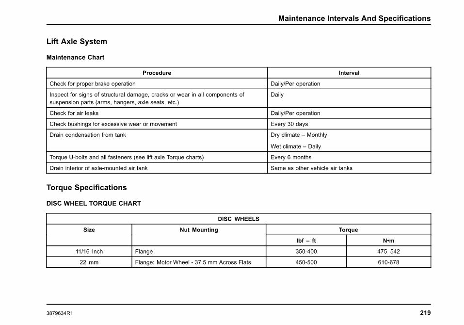
Maintenance Intervals And Specifications
Lift Axle System
Maintenance Chart
Procedure Interval
Check for proper brake operation Daily/Per operation
Inspect for signs of structural damage, cracks or wear in all components ofsuspension parts (arms, hangers, axle seats, etc.)
Daily
Check for air leaks Daily/Per operation
Check bushings for excessive wear or movement Every 30 days
Drain condensation from tank Dry climate – Monthly
Wet climate – Daily
Torque U-bolts and all fasteners (see lift axle Torque charts) Every 6 months
Drain interior of axle-mounted air tank Same as other vehicle air tanks
Torque Specifications
DISC WHEEL TORQUE CHART
DISC WHEELS
TorqueSize Nut Mounting
lbf – ft N•m
11/16 Inch Flange 350-400 475–542
22 mm Flange: Motor Wheel - 37.5 mm Across Flats 450-500 610-678
3879634R1 219

Maintenance Intervals And Specifications
DISC WHEELS
22 mm Flange: International®/Budd - 33 mm AcrossFlats
450-500 610-678
NOTE: Do not use lubrication on dry threads. Where excessive corrosion exists, a light coat of lubricant on first three threads of stud on bolt ispermitted. Keep lubricant away from:
• hex nut and rim clamp contact surfaces;
• flange nut washer surface and flat on disc wheel.
220 3879634R1

Maintenance Intervals And Specifications
U-BOLT NUT TORQUE CHART
TorqueFeature Code Rear Suspension Capacity and Type
lbf - ft N • m
14SAB 23,000-lb Capacity, RR, Spring, Single, with 3 Torque Rods 400-425 542-576
14SAH 18,500-lb Capacity, RR, Spring, Single Vari-Rate 370-400 502-542
14SAL 31,000-lb Capacity, RR, Spring, Single Vari-Rate, with 4,500-lb Auxiliary MultileafSprings
370-400 502-542
14SAM 20,000-lb Capacity, RR, Springs, Vari-Rate 370-400 502-542
14SAN 23,500-lb Capacity, RR, Spring, Single, Vari-Rate 370-400 502-542
14SBM 31,000-lb Capacity, RR, Spring, Single with 3 Torque Rods 400-425 542-576
14SZB 4,500-lb Capacity, Rear Auxiliary Multileaf Springs 370-400 502-542
14TBJ 20,000-lb Capacity, International Air Suspension (IROS) 370-400 502-542
14TBZ 23,000-lb Capacity, Single, Air (Hendrickson PRIMAAX EX) 350-400 475-542
14UNW, 14UNX, and 14UNY 46,000-lb Capacity, Tandem, Air (Hendrickson PRIMAAX EX), with 72 inch, 55inch, and 60 inch axle spacing.
350-400 475-542
14UNA 40,000-lb Capacity, International 4-Spring, Multileaf 260-300 353-407
14UNL, 14UNM, 14UNN,14UNS, 14UNT, and 14UNU
40,000-lb Capacity, International Air Suspension (IROS) 370-400 502-542
14VAD 18,500-lb Capacity, RR, Springs, Vari-Rate, with 4,500-lb Auxiliary Rubber Spring 370-400 502-542
14VAG 20,000-lb Capacity, RR, Springs, Vari-Rate, with 4,500-lb Auxiliary Rubber Spring 370-400 502-542
14VAH 23,500-lb Capacity, RR, Springs, Vari-Rate, with 4,500-lb Auxiliary Rubber Spring 370-400 502-542
14VAJ 31,000-lb Capacity, RR, Springs, Vari-Rate, with 4,500-lb Auxiliary Rubber Spring 370-400 502-542
NOTE: For all other vendor supplied suspensions, refer to vendor’s website for proper torque specifications.
3879634R1 221

Maintenance Intervals And Specifications
TorqueFeature Code Front Suspension Capacity and Type
lbf - ft N • m
3ACP 12,000-lb Capacity, Multileaf , Shackle Type 260-300 353-407
3ACR 18,000-lb Capacity, Multileaf , Shackle Type 260-300 353-407
20,000-lb Capacity, Multileaf , Shackle Type 260-300 353-4073ACS
20,000-lb Capacity, Multileaf , Shackle Type, (with SBA and CAT Engine) 325-400 441-542
10,000-lb Capacity, Parabolic Taper Leaf 260-300 353-4073ADB
10,000-lb to 20,000-lb Capacity, Parabolic Taper Leaf, (with SBA and CAT Engine) 325-400 441-542
3ADC 12,000-lb Capacity, Parabolic Taper Leaf 260-300 353-407
3ADD 14,000-lb Capacity, Parabolic Taper Leaf 260-300 353-407
3ADE 16,000-lb Capacity, Parabolic Taper Leaf 260-300 353-407
3ADG 18,000-lb Capacity, Parabolic Taper Leaf 260-300 353-407
20,000-lb Capacity, Parabolic Taper Leaf 260-300 353-4073AGA
20,000-lb Capacity, Parabolic Taper Leaf, (with Set Back Axle and CAT Engine) 325-400 441-542
3AGU 14,000-lb Capacity, Multileaf , Shackle Type 260-300 353-407
3AHL 22,000-lb Capacity, Parabolic Taper Leaf 325-400 441-542
3WAJ Auxiliary Air Bag Springs (Right Side) 260-300 353-407
3WAK Auxiliary Air Bag Springs (Left Side) 260-300 353-407
For vehicles with Hendrickson suspension (14UHK only), thetorque value of the four suspension saddle bolts, if applied at thehead, are 500 ft-lbs.(678 N•m). If applied at the nut, the torquevalue is 400 ft-lbs.(543 N•m).
See Lubrication and Maintenance Interval Chart, Axle U-bolts –Retorque, for maintenance retorque interval.
222 3879634R1

Maintenance Intervals And Specifications
SPRING U-BOLT CHECKS
Check U-Bolt Nuts and re-torque every 36,000 miles (57, 936km) after initial 1,000 mile re-torque.
LIFT AXLE TORQUE CHARTS
Fixed Axle U-Bolt Torque
The U-Bolts must be tightened and torqued using the followingcross pattern sequence and illustration. The U-Bolt Torque chartapplies only to Fixed lift axles.
1. Tighten 1 and 4 to partial torque.
2. Tighten 2 and 3 to partial torque.
3. Repeat steps 1 and 2 tightening all four bolts to full torque.
Lift Axle U-Bolt Nut Torque Chart
U-Bolt Size(UNF – Grade 8)Size in inches
3/8 1/2 5/8 3/4 7/8 1 1 1/8
Min. Torque(lbf-ft)
15 40 120 200 400 650 800
Max. Torque(lbf-ft)
20 60 150 250 450 750 900
NOTE: Torque values DO NOT apply to air springs or lowergrade fasteners.
The following chart applies to both Steerable and Fixed LiftAxles.
Capscrew/Bolt Torque Chart
Capscrew-Bolts (UNF –Grade 8) Size
in inches
3/8 1/2 5/8 3/4 7/8 1 1 1/8
Min. Torque(lbf-ft)
25 50 150 300 500 700 900
Max. Torque(lbf-ft)
35 75 200 350 550 800 1000
NOTE: Torque values DO NOT apply to U-BOLTS.
3879634R1 223

Maintenance Intervals And Specifications
Fuse Charts
The following fuse illustrations represent the fuse panel layouts.The actual vehicle fuse panels will vary depending on the vehicleoptions.
224 3879634R1

Maintenance Intervals And Specifications
WorkStar® Series Light Information
Lamp Description Candlepower or Watt Bulb P/N
Cab Dome Light 12 Watts 211-2
Cab Mount Clearance/Marker Light 3 CP GE193
Headlight 65 Watts GE9007
Fog Light 56 Watts VH550
Front Park/Marker/Turn Light 2356
Side Marker Light 2548
Tail/Brake/Turn Light 32/3 CP 1157
Back-up Light 32 CP GE1156
Ashtray Light N/A N/A
Filter List
Filter part numbers and/or specifications may change during thelife-cycle of this vehicle. Current information on the appropriate
chassis and engine filters for your vehicle can be obtained bycontacting your local International dealer parts department. Ifyou need assistance finding a local International dealer, use theDealer Locator at internationaltrucks.com.
3879634R1 225

Maintenance Intervals And Specifications
226 3879634R1

Customer Assistance
SECTION 8 — CUSTOMER ASSISTANCEService Information
The continued premium performance of this International®chassis can best be assured through proper servicing. This canbe accomplished in several ways.
International Truck Dealers … Your local InternationalTruck dealer provides an excellent resource – through hisknowledgeable, experienced, and well equipped service staff –to handle all your maintenance, repair, and replacement work.
Service Publications … Those persons who are properlytrained technicians with the facilities, equipment, tools, safetyinstructions and know-how to properly and safely service abus, medium duty and/or heavy duty chassis can purchasethe appropriate service manual sections applicable to specificvehicle components or areas of this International® vehicle.Engine diagnostic manuals and engine service manuals for allcurrent International® diesel engines are also available to thesetrained persons for purchase. Information on the purchase ofavailable service publications for this chassis can be found onthe internationaltrucks.com Web site, or by contacting your localInternational dealer.
These service resources are also available via the Internet, byan annual subscription to the Fleet ISIS® Web site, or via theiService DVD. Information on the Fleet ISIS Web site’s content,
availability, and fee structure can be obtained by contactingyour local International Truck dealer or, in the case of a NationalAccount, an International Fleet Service Manager.
The iService DVD contains all currently available chassis andcomponent service information, including TSI letters, ElectricalCircuit Diagrams, Electrical System Troubleshooting and othertechnical information, for virtually all International® models andMaxxForce® engines.
International Truck Warranty Program
Standard Warranty • Optional Service Contracts • CustomService Contracts • Performance PM® Service
The International Truck Warranty Program provides Internationalcustomers with a better choice when it comes to StandardWarranty and Service Contract Coverage. The StandardWarranty is the first tier of the International Truck WarrantyProgram. It provides the foundation for all extended coverages.
Vehicle Coverage, Towing, Engine and Engine Electronics,Major Component, and Pre-Packaged System Componentprotection can be obtained under the International WarrantyProgram through Optional Service Contracts.
3879634R1 227

Customer Assistance
Custom Service Contracts, the most flexible aspect of theInternational Truck Warranty Program, can provide extendedprotection that is specifically tailored to meet each customer’sspecific requirements.
Finally, through Performance PM® Service, customers canobtain a comprehensive preventative maintenance programdesigned to ensure consistency in pricing and the level ofservice received.
ADVANTAGES of International Truck Warranties
• Extends warranty protection to specified length andcomponent coverage to suit individual needs
• Honored at over 1,000 International Truck Dealer locationsin North America
• Stabilized and predictable maintenance costs
• Increased owner confidence and peace of mind
• Improved resale value on your vehicle – International TruckWarranties may be transferable for a nominal fee. Contactthe Service Contract Center 1-800-346-4429 option 1 fortransferability
• Most coverage is 100% parts and labor with NODEDUCTIBLES .
• Customized warranty programs are offered to suit yourneeds - your specification - your vocation
• International®, North America’s leader in truckmanufacturing, is also North America’s leader in warrantyvalue
• Optional Service Contracts, Custom Service Contracts, andPerformance PM® Service, designed to assure the lowestpossible cost of ownership, are also available
• Optional Service Contracts have been pre-packaged to fitmost common applications
• Custom Service Contracts are designed to meet yourindividual needs
HOW TO OBTAIN International Truck Warranties
• Standard Warranty: Your new International vehicle isautomatically registered in the International Truck Warrantysystem at the time of delivery. No further action on your partis required.
• Optional Service Contracts, Custom Service Contracts,or Performance PM® Service: These programs are soldexclusively through your International dealer. The vehiclemust also have coverage remaining under the StandardWarranty. For extended warranty purchases between, 181through 365 days from DTU and <100,000 miles (160,000km) an additional fee will be assessed. If you would like thepredictable cost of ownership and peace of mind providedby the International Truck Warranty Program, please contactyour International dealer today!
228 3879634R1

Index
SECTION 9 — INDEXA
ABS Connections and Sensors. . . . . . . . . . . . . . . . . . . . . . . . . . . . . . . . .176ABS Operation. . . . . . . . . . . . . . . . . . . . . . . . . . . . . . . . . . . . . . . . . . . . . .110, 154ABS Self-Check. . . . . . . . . . . . . . . . . . . . . . . . . . . . . . . . . . . . . . . . . . . . . . . . . .154Accessory Feed Connections. . . . . . . . . . . . . . . . . . . . . . . . . . . . . . . . . . .179Additional Unsafe Practices. . . . . . . . . . . . . . . . . . . . . . . . . . . . . . . . . . . . .115Adjustable Tilt/Telescoping Steering Column.. . . . . . . . . . . . . . . . .104After the Engine Starts. . . . . . . . . . . . . . . . . . . . . . . . . . . . . . . . . . . . . . . . . . . .95Air Brake Bendix® ABS-6 . . . . . . . . . . . . . . . . . . . . . . . . . . . . . . . . . . . . . . .155Air Brakes. . . . . . . . . . . . . . . . . . . . . . . . . . . . . . . . . . . . . . . . . . . . . . . . . . .148, 173
ABS Operation. . . . . . . . . . . . . . . . . . . . . . . . . . . . . . . . . . . . . . . . . . . . . . . . .154ABS Self-Check. . . . . . . . . . . . . . . . . . . . . . . . . . . . . . . . . . . . . . . . . . . . . . . .154Air Brake Bendix® ABS-6 . . . . . . . . . . . . . . . . . . . . . . . . . . . . . . . . . . . .155Air Dryer. . . . . . . . . . . . . . . . . . . . . . . . . . . . . . . . . . . . . . . . . . . . . . . . . . . . . . . .151Air Gauge, Low Air Pressure Beeper and WarningIndicator. . . . . . . . . . . . . . . . . . . . . . . . . . . . . . . . . . . . . . . . . . . . . . . . . . . . . . .149
Antilock Brake System (ABS). . . . . . . . . . . . . . . . . . . . . . . . . . . . . . . . .153Antilock Driving Tips. . . . . . . . . . . . . . . . . . . . . . . . . . . . . . . . . . . . . . . . . . .155Brake Application. . . . . . . . . . . . . . . . . . . . . . . . . . . . . . . . . . . . . . . . . . . . . .149Core ABS Functions. . . . . . . . . . . . . . . . . . . . . . . . . . . . . . . . . . . . . . . . . . .155Inspection and Adjustment. . . . . . . . . . . . . . . . . . . . . . . . . . . . . . . . . . . .173Parking Brake. . . . . . . . . . . . . . . . . . . . . . . . . . . . . . . . . . . . . . . . . . . . . . . . . .149Parking Brake Alarm.. . . . . . . . . . . . . . . . . . . . . . . . . . . . . . . . . . . . . . . . . .153Parking Brake Indicator. . . . . . . . . . . . . . . . . . . . . . . . . . . . . . . . . . . . . . .153Parking Brake Reset. . . . . . . . . . . . . . . . . . . . . . . . . . . . . . . . . . . . . . . . . . .150Reservoir Moisture Draining. . . . . . . . . . . . . . . . . . . . . . . . . . . . . . . . . .151Trailer Air Supply and Parking Brake Modular Controls. . .152Trailer Brake Hand Control. . . . . . . . . . . . . . . . . . . . . . . . . . . . . . . . . . .151
Air Cleaner Element Service. . . . . . . . . . . . . . . . . . . . . . . . . . . . . . . . . . . .182Air Compressor Cycling. . . . . . . . . . . . . . . . . . . . . . . . . . . . . . . . . . . . . . . . . .112
A (CONT.)Air Conditioning. . . . . . . . . . . . . . . . . . . . . . . . . . . . . . . . . . . . . . . . . . . . . . . . . . . .82Air Conditioning Service Checks. . . . . . . . . . . . . . . . . . . . . . . . . . . . . . . .168
Front Access HVAC Filter. . . . . . . . . . . . . . . . . . . . . . . . . . . . . . . . . . . . .169HVAC Filters. . . . . . . . . . . . . . . . . . . . . . . . . . . . . . . . . . . . . . . . . . . . . . . . . . . .168Recirculation Filters. . . . . . . . . . . . . . . . . . . . . . . . . . . . . . . . . . . . . . . . . . . .169Side Access HVAC Filter. . . . . . . . . . . . . . . . . . . . . . . . . . . . . . . . . . . . . .168
Air Dryer. . . . . . . . . . . . . . . . . . . . . . . . . . . . . . . . . . . . . . . . . . . . . . . . . . . . .151, 174Desiccant Filter. . . . . . . . . . . . . . . . . . . . . . . . . . . . . . . . . . . . . . . . . . . . . . . . .175Heater. . . . . . . . . . . . . . . . . . . . . . . . . . . . . . . . . . . . . . . . . . . . . . . . . . . . . . . . . . .175Purge Valve. . . . . . . . . . . . . . . . . . . . . . . . . . . . . . . . . . . . . . . . . . . . . . . . . . . . .175
Air Gauge, Low Air Pressure Beeper and WarningIndicator. . . . . . . . . . . . . . . . . . . . . . . . . . . . . . . . . . . . . . . . . . . . . . . . . . . . . . . . . .149
Air Induction System.. . . . . . . . . . . . . . . . . . . . . . . . . . . . . . . . . . . . . . . . . . . .180Air Intake System.. . . . . . . . . . . . . . . . . . . . . . . . . . . . . . . . . . . . . . . . . . . . . . . .190Air Parking Brake or Power Parking Brake. . . . . . . . . . . . . . . . . . . .125Air Reservoir/Tanks Moisture Draining. . . . . . . . . . . . . . . . . . . . . . . . .175Air Restriction Gauge. . . . . . . . . . . . . . . . . . . . . . . . . . . . . . . . . . . . . . . . . . . .181Air Suspension Dump (ASD) Switch (Optional). . . . . . . . . . . . . . .139Air Suspension System Faults. . . . . . . . . . . . . . . . . . . . . . . . . . . . . . . . . .140Alignment. . . . . . . . . . . . . . . . . . . . . . . . . . . . . . . . . . . . . . . . . . . . . . . . . . . . . . . . . .171Allison Generation IV T-Bar Gearshift Control. . . . . . . . . . . . . . . . .126Allison Transmission with “P” – (Park) Park Pawl Mechanism or“PB” – Parking Brake Position. . . . . . . . . . . . . . . . . . . . . . . . . . . . . . . . .123
Allison Transmissions. . . . . . . . . . . . . . . . . . . . . . . . . . . . . . . . . . . . . . . . . . . .123Alternator. . . . . . . . . . . . . . . . . . . . . . . . . . . . . . . . . . . . . . . . . . . . . . . . . . . . . . . . . .106Ammeter. . . . . . . . . . . . . . . . . . . . . . . . . . . . . . . . . . . . . . . . . . . . . . . . . . . . . . . . . . .106Antifreeze. . . . . . . . . . . . . . . . . . . . . . . . . . . . . . . . . . . . . . . . . . . . . . . . . . . . . . . . . .114AntiFreeze. . . . . . . . . . . . . . . . . . . . . . . . . . . . . . . . . . . . . . . . . . . . . . . . . . . . . . . . .189Antilock Brake System (ABS). . . . . . . . . . . . . . . . . . . . . . . . . . . . . . . . . . .153
3879634R1 229

Index
A (CONT.)Antilock Driving Tips. . . . . . . . . . . . . . . . . . . . . . . . . . . . . . . . . . . . . . . . . . . . . .155Approved Tire and Rim Combinations. . . . . . . . . . . . . . . . . . . . . . . . .218Assistance Guide. . . . . . . . . . . . . . . . . . . . . . . . . . . . . . . . . . . . . . . . . . . . . . . . . . . .1ATC OFF ROAD or MUD/SNOW Switch. . . . . . . . . . . . . . . . . . . . . . .156ATC System Check. . . . . . . . . . . . . . . . . . . . . . . . . . . . . . . . . . . . . . . . . . . . . . .156Auto Neutral. . . . . . . . . . . . . . . . . . . . . . . . . . . . . . . . . . . . . . . . . . . . . . . . . . . . . . .129Automatic Door Lock Function. . . . . . . . . . . . . . . . . . . . . . . . . . . . . . . . . . .86Automatic Transmission Operating Temperature. . . . . . . . . . . . .131Automatic Transmission Operation. . . . . . . . . . . . . . . . . . . . . . . . . . . . .110Automatic Transmissions. . . . . . . . . . . . . . . . . . . . . . . . . . . . . . . . . .123, 192
Air Parking Brake or Power Parking Brake. . . . . . . . . . . . . . . . . .125Allison Generation IV T-Bar Gearshift Control. . . . . . . . . . . . . .126Allison Transmission with “P” – (Park) Park Pawl Mechanismor “PB” – Parking Brake Position. . . . . . . . . . . . . . . . . . . . . . . . . . .123
Allison Transmissions. . . . . . . . . . . . . . . . . . . . . . . . . . . . . . . . . . . . . . . . .123Auto Neutral. . . . . . . . . . . . . . . . . . . . . . . . . . . . . . . . . . . . . . . . . . . . . . . . . . . .129Automatic Transmission Operating Temperature. . . . . . . . . . .131Backup Alarm. . . . . . . . . . . . . . . . . . . . . . . . . . . . . . . . . . . . . . . . . . . . . . . . . .129Main Transmission Controls. . . . . . . . . . . . . . . . . . . . . . . . . . . . . . . . . .128Manual Parking Brake. . . . . . . . . . . . . . . . . . . . . . . . . . . . . . . . . . . . . . . . .125Operation of the Allison Generation IV GearshiftControls. . . . . . . . . . . . . . . . . . . . . . . . . . . . . . . . . . . . . . . . . . . . . . . . . . . . . . . .125
Operation of the Allison Generation IV Push-button ShiftSelector. . . . . . . . . . . . . . . . . . . . . . . . . . . . . . . . . . . . . . . . . . . . . . . . . . . . . . . .127
Operation of the Column-Mounted Shifter. . . . . . . . . . . . . . . . . .128Parking The Vehicle. . . . . . . . . . . . . . . . . . . . . . . . . . . . . . . . . . . . . . . . . . .124Power Take Off Control. . . . . . . . . . . . . . . . . . . . . . . . . . . . . . . . . . . . . . .131Preparing to Drive the Vehicle. . . . . . . . . . . . . . . . . . . . . . . . . . . . . . . .125Torque Lock. . . . . . . . . . . . . . . . . . . . . . . . . . . . . . . . . . . . . . . . . . . . . . . . . . . .126
Auxiliary Gauge/Switch Package (AGSP) (Optional). . . . . . . . . .78Panel Component Arrangements (Optional). . . . . . . . . . . . . . . . .78
A (CONT.)Available Cabs. . . . . . . . . . . . . . . . . . . . . . . . . . . . . . . . . . . . . . . . . . . . . . . . . . . . . .11
Crew Cab.. . . . . . . . . . . . . . . . . . . . . . . . . . . . . . . . . . . . . . . . . . . . . . . . . . . . . . . .11Extended Cab.. . . . . . . . . . . . . . . . . . . . . . . . . . . . . . . . . . . . . . . . . . . . . . . . . . .11Standard Cab. . . . . . . . . . . . . . . . . . . . . . . . . . . . . . . . . . . . . . . . . . . . . . . . . . . .11
Available Models. . . . . . . . . . . . . . . . . . . . . . . . . . . . . . . . . . . . . . . . . . . . . . . . . . . .9Axle and Suspension Conversions. . . . . . . . . . . . . . . . . . . . . . . . . . . . .140Axle Operating Temperature. . . . . . . . . . . . . . . . . . . . . . . . . . . . . . . . . . . .136Axle Shift Only. . . . . . . . . . . . . . . . . . . . . . . . . . . . . . . . . . . . . . . . . . . . . . . . . . . .135Axles. . . . . . . . . . . . . . . . . . . . . . . . . . . . . . . . . . . . . . . . . . . . . . . . . . . . . . . . . . . . . . .170
Front Axle. . . . . . . . . . . . . . . . . . . . . . . . . . . . . . . . . . . . . . . . . . . . . . . . . . . . . . .170Alignment. . . . . . . . . . . . . . . . . . . . . . . . . . . . . . . . . . . . . . . . . . . . . . . . . . . .171Inspection and Lubrication. . . . . . . . . . . . . . . . . . . . . . . . . . . . . . . . .170Normal Maintenance. . . . . . . . . . . . . . . . . . . . . . . . . . . . . . . . . . . . . . . .170
Front Drive Axle and Transfer Case (Optional). . . . . . . . . . . . .171Inspection and Lubrication. . . . . . . . . . . . . . . . . . . . . . . . . . . . . . . . .171
Rear Axle – Inspection and Lubrication. . . . . . . . . . . . . . . . . . . . .171Axles and Suspensions. . . . . . . . . . . . . . . . . . . . . . . . . . . . . . . . . . . . . . . . . .136
Air Suspension Dump (ASD) Switch (Optional). . . . . . . . . . . .139Air Suspension System Faults. . . . . . . . . . . . . . . . . . . . . . . . . . . . . . . .140Axle and Suspension Conversions. . . . . . . . . . . . . . . . . . . . . . . . . . .140Axle Operating Temperature. . . . . . . . . . . . . . . . . . . . . . . . . . . . . . . . . .136Front Axle (4X4, 6X6). . . . . . . . . . . . . . . . . . . . . . . . . . . . . . . . . . . . . . . . .136Gross Weight (Axle – Vehicle). . . . . . . . . . . . . . . . . . . . . . . . . . . . . . . .136International® Ride Optimized Suspension (IROS)(Optional). . . . . . . . . . . . . . . . . . . . . . . . . . . . . . . . . . . . . . . . . . . . . . . . . . . . . .139
Operation. . . . . . . . . . . . . . . . . . . . . . . . . . . . . . . . . . . . . . . . . . . . . . . . . . . . . . .137Transfer Case. . . . . . . . . . . . . . . . . . . . . . . . . . . . . . . . . . . . . . . . . . . . . . . . . .137
BBackup Alarm. . . . . . . . . . . . . . . . . . . . . . . . . . . . . . . . . . . . . . . . . . . . . . . . . . . . .129Basic Functions of Steering Wheel Controls. . . . . . . . . . . . . . . . . . . .70
230 3879634R1

Index
B (CONT.)Batteries. . . . . . . . . . . . . . . . . . . . . . . . . . . . . . . . . . . . . . . . . . . . . . . . . . . . . . . . . . .177Battery. . . . . . . . . . . . . . . . . . . . . . . . . . . . . . . . . . . . . . . . . . . . . . . . . . . . . . . . . . . . .106Battery Cables. . . . . . . . . . . . . . . . . . . . . . . . . . . . . . . . . . . . . . . . . . . . . . . . . . . .178Battery Disconnect Switch. . . . . . . . . . . . . . . . . . . . . . . . . . . . . . . . . . . . . . .107Bobtail Proportioning System. . . . . . . . . . . . . . . . . . . . . . . . . . . . . . . . . . .158Body. . . . . . . . . . . . . . . . . . . . . . . . . . . . . . . . . . . . . . . . . . . . . . . . . . . . . . . . . . . . . . .190Brake Application. . . . . . . . . . . . . . . . . . . . . . . . . . . . . . . . . . . . . . . . . . . . . . . . .149Brakes. . . . . . . . . . . . . . . . . . . . . . . . . . . . . . . . . . . . . . . . . . . . . . . . . . . . . . .147, 172
ABS Connections and Sensors. . . . . . . . . . . . . . . . . . . . . . . . . . . . . .176Air Brakes. . . . . . . . . . . . . . . . . . . . . . . . . . . . . . . . . . . . . . . . . . . . . . . . .148, 173
ABS Operation. . . . . . . . . . . . . . . . . . . . . . . . . . . . . . . . . . . . . . . . . . . . . . .154ABS Self-Check. . . . . . . . . . . . . . . . . . . . . . . . . . . . . . . . . . . . . . . . . . . . .154Air Brake Bendix® ABS-6 . . . . . . . . . . . . . . . . . . . . . . . . . . . . . . . . .155Air Dryer. . . . . . . . . . . . . . . . . . . . . . . . . . . . . . . . . . . . . . . . . . . . . . . . . . . . . .151Air Gauge, Low Air Pressure Beeper and WarningIndicator. . . . . . . . . . . . . . . . . . . . . . . . . . . . . . . . . . . . . . . . . . . . . . . . . . . . .149
Antilock Brake System (ABS). . . . . . . . . . . . . . . . . . . . . . . . . . . . . .153Antilock Driving Tips. . . . . . . . . . . . . . . . . . . . . . . . . . . . . . . . . . . . . . . .155Brake Application. . . . . . . . . . . . . . . . . . . . . . . . . . . . . . . . . . . . . . . . . . . .149Core ABS Functions. . . . . . . . . . . . . . . . . . . . . . . . . . . . . . . . . . . . . . . .155Inspection and Adjustment. . . . . . . . . . . . . . . . . . . . . . . . . . . . . . . . .173Parking Brake. . . . . . . . . . . . . . . . . . . . . . . . . . . . . . . . . . . . . . . . . . . . . . . .149Parking Brake Alarm. . . . . . . . . . . . . . . . . . . . . . . . . . . . . . . . . . . . . . . .153Parking Brake Indicator. . . . . . . . . . . . . . . . . . . . . . . . . . . . . . . . . . . . .153Parking Brake Reset. . . . . . . . . . . . . . . . . . . . . . . . . . . . . . . . . . . . . . . .150Reservoir Moisture Draining. . . . . . . . . . . . . . . . . . . . . . . . . . . . . . .151Trailer Air Supply and Parking Brake ModularControls. . . . . . . . . . . . . . . . . . . . . . . . . . . . . . . . . . . . . . . . . . . . . . . . . . . . .152
Trailer Brake Hand Control. . . . . . . . . . . . . . . . . . . . . . . . . . . . . . . . .151Air Dryer. . . . . . . . . . . . . . . . . . . . . . . . . . . . . . . . . . . . . . . . . . . . . . . . . . . . . . . .174
Desiccant Filter. . . . . . . . . . . . . . . . . . . . . . . . . . . . . . . . . . . . . . . . . . . . . .175
B (CONT.)Brakes (cont.)
Heater. . . . . . . . . . . . . . . . . . . . . . . . . . . . . . . . . . . . . . . . . . . . . . . . . . . . . . . .175Purge Valve. . . . . . . . . . . . . . . . . . . . . . . . . . . . . . . . . . . . . . . . . . . . . . . . . .175
Air Reservoir/Tanks Moisture Draining. . . . . . . . . . . . . . . . . . . . . .175ATC OFF ROAD or MUD/SNOW Switch. . . . . . . . . . . . . . . . . . . .156ATC System Check. . . . . . . . . . . . . . . . . . . . . . . . . . . . . . . . . . . . . . . . . . . .156Downhill Operation. . . . . . . . . . . . . . . . . . . . . . . . . . . . . . . . . . . . . . . . . . . .147Stability Control Systems – Bendix® ESP. . . . . . . . . . . . . . . . . .157Traction Control (If Equipped). . . . . . . . . . . . . . . . . . . . . . . . . . . . . . . .156
Bright Metal Care. . . . . . . . . . . . . . . . . . . . . . . . . . . . . . . . . . . . . . . . . . . . . . . . .176
CCab.. . . . . . . . . . . . . . . . . . . . . . . . . . . . . . . . . . . . . . . . . . . . . . . . . . . . . . . . . . . . . . . .176
Care of Vehicle. . . . . . . . . . . . . . . . . . . . . . . . . . . . . . . . . . . . . . . . . . . . . . . . .176Bright Metal Care. . . . . . . . . . . . . . . . . . . . . . . . . . . . . . . . . . . . . . . . . . . .176Exposed Rubber and Unpainted Plastic Parts. . . . . . . . . . .176Upholstery Care. . . . . . . . . . . . . . . . . . . . . . . . . . . . . . . . . . . . . . . . . . . . .176Washing and Waxing. . . . . . . . . . . . . . . . . . . . . . . . . . . . . . . . . . . . . . .176
Cab Controls. . . . . . . . . . . . . . . . . . . . . . . . . . . . . . . . . . . . . . . . . . . . . . . . . . . . . . .90Cab Doors and Locks. . . . . . . . . . . . . . . . . . . . . . . . . . . . . . . . . . . . . . . . . . . . .83Cab Entry and Exit. . . . . . . . . . . . . . . . . . . . . . . . . . . . . . . . . . . . . . . . . . . . . . . . .14Cab Interior Inspection. . . . . . . . . . . . . . . . . . . . . . . . . . . . . . . . . . . . . . . . . . . .34Canadian Registered Vehicles. . . . . . . . . . . . . . . . . . . . . . . . . . . . . . . . . . . . .5Capscrew/Bolt Torque Chart. . . . . . . . . . . . . . . . . . . . . . . . . . . . . . . . . . . .223Care of Seat Belts. . . . . . . . . . . . . . . . . . . . . . . . . . . . . . . . . . . . . . . . . . . . . . . . .93Care of Vehicle. . . . . . . . . . . . . . . . . . . . . . . . . . . . . . . . . . . . . . . . . . . . . . . . . . .176
Bright Metal Care. . . . . . . . . . . . . . . . . . . . . . . . . . . . . . . . . . . . . . . . . . . . . .176Exposed Rubber and Unpainted Plastic Parts. . . . . . . . . . . . . .176Upholstery Care. . . . . . . . . . . . . . . . . . . . . . . . . . . . . . . . . . . . . . . . . . . . . . . .176Washing and Waxing. . . . . . . . . . . . . . . . . . . . . . . . . . . . . . . . . . . . . . . . . .176
Cautions and Warnings. . . . . . . . . . . . . . . . . . . . . . . . . . . . . . . . . . . . . . . . . . . . .1
3879634R1 231

Index
C (CONT.)Center Dash Panel/Wing Panel. . . . . . . . . . . . . . . . . . . . . . . . . . . . . . . . . .74
Switches. . . . . . . . . . . . . . . . . . . . . . . . . . . . . . . . . . . . . . . . . . . . . . . . . . . . . . . . . .75Certified Clean Idle. . . . . . . . . . . . . . . . . . . . . . . . . . . . . . . . . . . . . . . . . . . . . . .111Charge Air Cooler. . . . . . . . . . . . . . . . . . . . . . . . . . . . . . . . . . . . . . . . . . . . . . . .108Charge Air Cooler And Radiator Core Inspection AndCleaning. . . . . . . . . . . . . . . . . . . . . . . . . . . . . . . . . . . . . . . . . . . . . . . . . . . . . . . . . .185Inspection and Cleaning. . . . . . . . . . . . . . . . . . . . . . . . . . . . . . . . . . . . . .185
Chassis Lubrication. . . . . . . . . . . . . . . . . . . . . . . . . . . . . . . . . . . . . . . . . . . . . .167Checking Inflation. . . . . . . . . . . . . . . . . . . . . . . . . . . . . . . . . . . . . . . . . . . . . . . .196Circuit Breakers, Fuses, and Fusible Links. . . . . . . . . . . . . . . . . . . .107Cleaning. . . . . . . . . . . . . . . . . . . . . . . . . . . . . . . . . . . . . . . . . . . . . . . . . . . . . . . . . . .191Climate Control. . . . . . . . . . . . . . . . . . . . . . . . . . . . . . . . . . . . . . . . . . . . . . . . . . . . .80
Air Conditioning. . . . . . . . . . . . . . . . . . . . . . . . . . . . . . . . . . . . . . . . . . . . . . . . . .82Dehumidification. . . . . . . . . . . . . . . . . . . . . . . . . . . . . . . . . . . . . . . . . . . . . . . . .83
Clutch. . . . . . . . . . . . . . . . . . . . . . . . . . . . . . . . . . . . . . . . . . . . . . . . . . . . . . . . . . . . . .177Pedal Free-Travel. . . . . . . . . . . . . . . . . . . . . . . . . . . . . . . . . . . . . . . . . . . . . .177
Clutch Brake (Vehicles with Nonsynchronized Transmission) –Vehicle Not Moving. . . . . . . . . . . . . . . . . . . . . . . . . . . . . . . . . . . . . . . . . . . . .121
Clutch Precautions. . . . . . . . . . . . . . . . . . . . . . . . . . . . . . . . . . . . . . . . . . . . . . .122Cold Weather. . . . . . . . . . . . . . . . . . . . . . . . . . . . . . . . . . . . . . . . . . . . . . . . . . . . .100
Cold Weather Operation. . . . . . . . . . . . . . . . . . . . . . . . . . . . . . . . . . . . . .101Cold Weather Starting. . . . . . . . . . . . . . . . . . . . . . . . . . . . . . . . . . . . . . . . .101Engine Idling. . . . . . . . . . . . . . . . . . . . . . . . . . . . . . . . . . . . . . . . . . . . . . . . . . . .101Winter Front Usage.. . . . . . . . . . . . . . . . . . . . . . . . . . . . . . . . . . . . . . . . . . .102Winter/Engine Intake Operation. . . . . . . . . . . . . . . . . . . . . . . . . . . . . .101
Cold Weather Operation. . . . . . . . . . . . . . . . . . . . . . . . . . . . . . . . . . . . . . . . .101Cold Weather Starting. . . . . . . . . . . . . . . . . . . . . . . . . . . . . . . . . . . . . . . . . . .101Compass Declination Zone Set Procedure. . . . . . . . . . . . . . . . . . . . . .52Compass Directional Calibration Procedure. . . . . . . . . . . . . . . . . . . .55Component Code Numbers. . . . . . . . . . . . . . . . . . . . . . . . . . . . . . . . . . . . . . . .2
Line Set Ticket. . . . . . . . . . . . . . . . . . . . . . . . . . . . . . . . . . . . . . . . . . . . . . . . . . . .2
C (CONT.)Components Requiring Fluid Check and Fill. . . . . . . . . . . . . . . . . .213Components Requiring Lubrication. . . . . . . . . . . . . . . . . . . . . . . . . . . . .212Connecting/Disconnecting a Trailer to a Vehicle with AirSuspension. . . . . . . . . . . . . . . . . . . . . . . . . . . . . . . . . . . . . . . . . . . . . . . . . . . . . .162
Controlled Traction Differential. . . . . . . . . . . . . . . . . . . . . . . . . . . . . . . . . .134Coolant and Optional Coolant Filter. . . . . . . . . . . . . . . . . . . . . . . . . . . .188Coolant Level. . . . . . . . . . . . . . . . . . . . . . . . . . . . . . . . . . . . . . . . . . . . . . . . . . . . .185Cooling System.. . . . . . . . . . . . . . . . . . . . . . . . . . . . . . . . . . . . . . . . . . . .113, 185
Antifreeze. . . . . . . . . . . . . . . . . . . . . . . . . . . . . . . . . . . . . . . . . . . . . . . . . . . . . . .114AntiFreeze. . . . . . . . . . . . . . . . . . . . . . . . . . . . . . . . . . . . . . . . . . . . . . . . . . . . . .189Coolant and Optional Coolant Filter. . . . . . . . . . . . . . . . . . . . . . . . .188Coolant Level. . . . . . . . . . . . . . . . . . . . . . . . . . . . . . . . . . . . . . . . . . . . . . . . . . .185Fan Clutch. . . . . . . . . . . . . . . . . . . . . . . . . . . . . . . . . . . . . . . . . . . . . . . . . . . . . .189Filling Instructions. . . . . . . . . . . . . . . . . . . . . . . . . . . . . . . . . . . . . . . . . . . . . .186Filling Instructions (MaxxForce® 11 and 13 Engines). . . . .187
Cooling System Refill Capacities. . . . . . . . . . . . . . . . . . . . . . . . . . . . . . .216Core ABS Functions. . . . . . . . . . . . . . . . . . . . . . . . . . . . . . . . . . . . . . . . . . . . .155Courtesy Lights. . . . . . . . . . . . . . . . . . . . . . . . . . . . . . . . . . . . . . . . . . . . . . . . . . . . .50Crankcase and Oil Filters. . . . . . . . . . . . . . . . . . . . . . . . . . . . . . . . . . . . . . . .216Crew Cab. . . . . . . . . . . . . . . . . . . . . . . . . . . . . . . . . . . . . . . . . . . . . . . . . . . . . . . . . . .11Cruise Control. . . . . . . . . . . . . . . . . . . . . . . . . . . . . . . . . . . . . . . . . . . . . . . . . . . . . .69
Basic Functions of Steering Wheel Controls. . . . . . . . . . . . . . . . .70Mobile Variable Speed Control (12VXV). . . . . . . . . . . . . . . . . . . . . .71Operational Procedures. . . . . . . . . . . . . . . . . . . . . . . . . . . . . . . . . . . . . . . .70Stationary Pre-Set Speed Control (12VXU). . . . . . . . . . . . . . . . . .71Stationary Variable Speed Control (12VXT). . . . . . . . . . . . . . . . . .71Throttle. . . . . . . . . . . . . . . . . . . . . . . . . . . . . . . . . . . . . . . . . . . . . . . . . . . . . . . . . . .70
Customer Security Guide for International Trucks. . . . . . . . . . . . . . .6
DDash Components. . . . . . . . . . . . . . . . . . . . . . . . . . . . . . . . . . . . . . . . . . . . . . . . .38
232 3879634R1

Index
D (CONT.)Daytime Running Lights (DRL). . . . . . . . . . . . . . . . . . . . . . . . . . . . . . . . . . .49Dehumidification. . . . . . . . . . . . . . . . . . . . . . . . . . . . . . . . . . . . . . . . . . . . . . . . . . .83Desiccant Filter. . . . . . . . . . . . . . . . . . . . . . . . . . . . . . . . . . . . . . . . . . . . . . . . . . .175Diesel Particulate Filter (DPF). . . . . . . . . . . . . . . . . . . . . . . . . . . . . . . . . .191
Cleaning. . . . . . . . . . . . . . . . . . . . . . . . . . . . . . . . . . . . . . . . . . . . . . . . . . . . . . . .191Regeneration. . . . . . . . . . . . . . . . . . . . . . . . . . . . . . . . . . . . . . . . . . . . . . . . . . .191
Direct Drive Warning Indicators. . . . . . . . . . . . . . . . . . . . . . . . . . . . . . . . . .47Disc Wheel Torque Chart. . . . . . . . . . . . . . . . . . . . . . . . . . . . . . . . . . . . . . . .219Dome Lighting. . . . . . . . . . . . . . . . . . . . . . . . . . . . . . . . . . . . . . . . . . . . . . . . . . . . . .50Door and Window Controls. . . . . . . . . . . . . . . . . . . . . . . . . . . . . . . . . . . . . . .83
Door Lock/Unlock. . . . . . . . . . . . . . . . . . . . . . . . . . . . . . . . . . . . . . . . . . . . . . .83Automatic Door Lock Function. . . . . . . . . . . . . . . . . . . . . . . . . . . . . .86Cab Doors and Locks. . . . . . . . . . . . . . . . . . . . . . . . . . . . . . . . . . . . . . . .83Door Opening/Unlock. . . . . . . . . . . . . . . . . . . . . . . . . . . . . . . . . . . . . . . .85Lock/Unlock from Interior. . . . . . . . . . . . . . . . . . . . . . . . . . . . . . . . . . . .85Remote Keyless Entry Operation (Optional). . . . . . . . . . . . . . .84
Windows.. . . . . . . . . . . . . . . . . . . . . . . . . . . . . . . . . . . . . . . . . . . . . . . . . . . . . . . . .86Manual Operation. . . . . . . . . . . . . . . . . . . . . . . . . . . . . . . . . . . . . . . . . . . . .86Mirror Controls. . . . . . . . . . . . . . . . . . . . . . . . . . . . . . . . . . . . . . . . . . . . . . . .86Power Operation. . . . . . . . . . . . . . . . . . . . . . . . . . . . . . . . . . . . . . . . . . . . . .86Vent Window. . . . . . . . . . . . . . . . . . . . . . . . . . . . . . . . . . . . . . . . . . . . . . . . . .87Window Lockout Function. . . . . . . . . . . . . . . . . . . . . . . . . . . . . . . . . . .86
Door Lock/Unlock. . . . . . . . . . . . . . . . . . . . . . . . . . . . . . . . . . . . . . . . . . . . . . . . . .83Automatic Door Lock Function. . . . . . . . . . . . . . . . . . . . . . . . . . . . . . . . .86Cab Doors and Locks. . . . . . . . . . . . . . . . . . . . . . . . . . . . . . . . . . . . . . . . . . .83Door Opening/Unlock. . . . . . . . . . . . . . . . . . . . . . . . . . . . . . . . . . . . . . . . . . .85Lock/Unlock from Interior. . . . . . . . . . . . . . . . . . . . . . . . . . . . . . . . . . . . . . .85
Locking the Door. . . . . . . . . . . . . . . . . . . . . . . . . . . . . . . . . . . . . . . . . . . . . .85Unlocking the Door. . . . . . . . . . . . . . . . . . . . . . . . . . . . . . . . . . . . . . . . . . .86
Remote Keyless Entry Operation (Optional). . . . . . . . . . . . . . . . .84Door Opening/Unlock. . . . . . . . . . . . . . . . . . . . . . . . . . . . . . . . . . . . . . . . . . . . . .85
D (CONT.)Double Clutch Procedures, Nonsynchronized. . . . . . . . . . . . . . . . .121Downhill Operation. . . . . . . . . . . . . . . . . . . . . . . . . . . . . . . . . . . . . . . . . . . . . . .147Drive Shafts. . . . . . . . . . . . . . . . . . . . . . . . . . . . . . . . . . . . . . . . . . . . . . . . . . . . . . .192Driver Reward. . . . . . . . . . . . . . . . . . . . . . . . . . . . . . . . . . . . . . . . . . . . . . . . . . . . . .87Driver-Controlled Differential Lock. . . . . . . . . . . . . . . . . . . . . . . . . . . . . .133Dual Tires Matching. . . . . . . . . . . . . . . . . . . . . . . . . . . . . . . . . . . . . . . . . . . . . .197Dual Tires Mixing. . . . . . . . . . . . . . . . . . . . . . . . . . . . . . . . . . . . . . . . . . . . . . . . .197
EEaton UltraShift® Transmissions (Optional). . . . . . . . . . . . . . . . . . .123Electrical. . . . . . . . . . . . . . . . . . . . . . . . . . . . . . . . . . . . . . . . . . . . . . . . . . . . .105, 177
Accessory Feed Connections. . . . . . . . . . . . . . . . . . . . . . . . . . . . . . . .179Alternator. . . . . . . . . . . . . . . . . . . . . . . . . . . . . . . . . . . . . . . . . . . . . . . . . . . . . . .106Ammeter. . . . . . . . . . . . . . . . . . . . . . . . . . . . . . . . . . . . . . . . . . . . . . . . . . . . . . . .106Batteries. . . . . . . . . . . . . . . . . . . . . . . . . . . . . . . . . . . . . . . . . . . . . . . . . . . . . . . .177Battery. . . . . . . . . . . . . . . . . . . . . . . . . . . . . . . . . . . . . . . . . . . . . . . . . . . . . . . . . .106Battery Cables. . . . . . . . . . . . . . . . . . . . . . . . . . . . . . . . . . . . . . . . . . . . . . . . .178Battery Disconnect Switch. . . . . . . . . . . . . . . . . . . . . . . . . . . . . . . . . . . .107Circuit Breakers, Fuses, and Fusible Links. . . . . . . . . . . . . . . . .107Electrical Charging and Starting System Test. . . . . . . . . . . . . .178Electrical System.. . . . . . . . . . . . . . . . . . . . . . . . . . . . . . . . . . . . . . . . . . . . . .105Fuses and Relays. . . . . . . . . . . . . . . . . . . . . . . . . . . . . . . . . . . . . . . . . . . . . .179Terminal Inspection-Cleaning-Corrosion Protection. . . . . . . .178
Electrical Charging and Starting System Test. . . . . . . . . . . . . . . . .178Electrical System.. . . . . . . . . . . . . . . . . . . . . . . . . . . . . . . . . . . . . . . . . . . .37, 105Emergency Starting Using Jumper Cables. . . . . . . . . . . . . . . . . . . .100Emission Control Systems.. . . . . . . . . . . . . . . . . . . . . . . . . . . . . . . . . . . . . . . . .5Enabling the Lift Axle System.. . . . . . . . . . . . . . . . . . . . . . . . . . . . . . . . . .145Engaging the Clutch. . . . . . . . . . . . . . . . . . . . . . . . . . . . . . . . . . . . . . . . . . . . . .120Engine. . . . . . . . . . . . . . . . . . . . . . . . . . . . . . . . . . . . . . . . . . . . . . . . . . . . . . .108, 179
Air Cleaner Element Service. . . . . . . . . . . . . . . . . . . . . . . . . . . . . . . . . .182
3879634R1 233

Index
E (CONT.)Engine (cont.)
Air Induction System.. . . . . . . . . . . . . . . . . . . . . . . . . . . . . . . . . . . . . . . . . .180Air Restriction Gauge.. . . . . . . . . . . . . . . . . . . . . . . . . . . . . . . . . . . . . . . . .181Charge Air Cooler. . . . . . . . . . . . . . . . . . . . . . . . . . . . . . . . . . . . . . . . . . . . . .108Charge Air Cooler And Radiator Core Inspection AndCleaning. . . . . . . . . . . . . . . . . . . . . . . . . . . . . . . . . . . . . . . . . . . . . . . . . . . . . . .185Inspection and Cleaning. . . . . . . . . . . . . . . . . . . . . . . . . . . . . . . . . . . .185
Cooling System.. . . . . . . . . . . . . . . . . . . . . . . . . . . . . . . . . . . . . . . . . . . . . . .185AntiFreeze. . . . . . . . . . . . . . . . . . . . . . . . . . . . . . . . . . . . . . . . . . . . . . . . . . .189Coolant and Optional Coolant Filter. . . . . . . . . . . . . . . . . . . . . . .188Coolant Level. . . . . . . . . . . . . . . . . . . . . . . . . . . . . . . . . . . . . . . . . . . . . . . .185Fan Clutch. . . . . . . . . . . . . . . . . . . . . . . . . . . . . . . . . . . . . . . . . . . . . . . . . . .189Filling Instructions. . . . . . . . . . . . . . . . . . . . . . . . . . . . . . . . . . . . . . . . . . .186Filling Instructions (MaxxForce® 11 and 13 Engines). . .187
Engine fluids and contaminated material. . . . . . . . . . . . . . . . . . . .180Frame.. . . . . . . . . . . . . . . . . . . . . . . . . . . . . . . . . . . . . . . . . . . . . . . . . . . . . . . . . .190Fuel System.. . . . . . . . . . . . . . . . . . . . . . . . . . . . . . . . . . . . . . . . . . . . . . . . . . .189
Fuel Tank Draining and Cleaning. . . . . . . . . . . . . . . . . . . . . . . . . .189Scheduled Maintenance. . . . . . . . . . . . . . . . . . . . . . . . . . . . . . . . . . . . . .180Tow Hooks, Tow Pins, and Pintle Hooks. . . . . . . . . . . . . . . . . . . .190Troubleshooting. . . . . . . . . . . . . . . . . . . . . . . . . . . . . . . . . . . . . . . . . . . . . . . .184
Engine Brake System Operation. . . . . . . . . . . . . . . . . . . . . . . . . . . . . . . .109Engine Brake, Retarder (Optional). . . . . . . . . . . . . . . . . . . . . . . . . . . . .108
ABS Operation. . . . . . . . . . . . . . . . . . . . . . . . . . . . . . . . . . . . . . . . . . . . . . . . .110Automatic Transmission Operation. . . . . . . . . . . . . . . . . . . . . . . . . . .110Engine Brake System Operation. . . . . . . . . . . . . . . . . . . . . . . . . . . . .109MaxxForce® 11 and 13 Engine Brake With EatonAutoShift®/UltraShift® Transmissions Special DriverInstructions. . . . . . . . . . . . . . . . . . . . . . . . . . . . . . . . . . . . . . . . . . . . . . . . . . . .109
Operational Modes. . . . . . . . . . . . . . . . . . . . . . . . . . . . . . . . . . . . . . . . . . . .109Engine fluids and contaminated material. . . . . . . . . . . . . . . . . . . . . .180
E (CONT.)Engine Idle Shutdown Timer (Optional). . . . . . . . . . . . . . . . . . . . . . . . .96
System Operation. . . . . . . . . . . . . . . . . . . . . . . . . . . . . . . . . . . . . . . . . . . . . . .96Engine Idling. . . . . . . . . . . . . . . . . . . . . . . . . . . . . . . . . . . . . . . . . . . . . . . . . . . . . .101Engine Noise Shields/Blankets. . . . . . . . . . . . . . . . . . . . . . . . . . . . . . . . .191Engine Oil. . . . . . . . . . . . . . . . . . . . . . . . . . . . . . . . . . . . . . . . . . . . . . . . . . . . . . . . .114Engine Performance Problems.. . . . . . . . . . . . . . . . . . . . . . . . . . . . . . . . .115Engine Serial Number. . . . . . . . . . . . . . . . . . . . . . . . . . . . . . . . . . . . . . . . . . . . .12Engine ShutDown.. . . . . . . . . . . . . . . . . . . . . . . . . . . . . . . . . . . . . . . . . . . . . . . . .95
Shut-Down Warning Indicator Or Beeper. . . . . . . . . . . . . . . . . . . . .95Engine Starting. . . . . . . . . . . . . . . . . . . . . . . . . . . . . . . . . . . . . . . . . . . . . . . . . . . . .94Engine Warning/Protection System (EWPS). . . . . . . . . . . . . . . . . . .111
Standard Engine Warning System 2-Way. . . . . . . . . . . . . . . . . . .111Exhaust Diesel Particulate Filter Regeneration. . . . . . . . . . . . . . . .117
Parked Regeneration Procedure. . . . . . . . . . . . . . . . . . . . . . . . . . . . .119Regeneration Inhibit Switch. . . . . . . . . . . . . . . . . . . . . . . . . . . . . . . . . . .119Three-Position Regeneration Inhibit Switch. . . . . . . . . . . . . . . . .120Two-Position Regeneration Inhibit Switch. . . . . . . . . . . . . . . . . . .120
Exhaust System.. . . . . . . . . . . . . . . . . . . . . . . . . . . . . . . . . . . . . . . . . . . . . . . . .191Exposed Rubber and Unpainted Plastic Parts. . . . . . . . . . . . . . . .176Extended Cab. . . . . . . . . . . . . . . . . . . . . . . . . . . . . . . . . . . . . . . . . . . . . . . . . . . . . .11Extended Cab Bunk (Optional). . . . . . . . . . . . . . . . . . . . . . . . . . . . . . . . . . .93Exterior Components. . . . . . . . . . . . . . . . . . . . . . . . . . . . . . . . . . . . . . . . . . . . . .13Exterior Lights Check. . . . . . . . . . . . . . . . . . . . . . . . . . . . . . . . . . . . . . . . . . . . . .16Exterior Noise Emissions. . . . . . . . . . . . . . . . . . . . . . . . . . . . . . . . . . . . . . . . . . .4
FFan Clutch. . . . . . . . . . . . . . . . . . . . . . . . . . . . . . . . . . . . . . . . . . . . . . . . . . . . . . . . .189Feature Codes. . . . . . . . . . . . . . . . . . . . . . . . . . . . . . . . . . . . . . . . . . . . . . . . . . . . .12Fifth Wheel and Coupling Area. . . . . . . . . . . . . . . . . . . . . . . . . . . . . . . . . . .33Fifth Wheel Operation. . . . . . . . . . . . . . . . . . . . . . . . . . . . . . . . . . . . . . . . . . . .162
Fifth Wheel Slide Switch (Optional). . . . . . . . . . . . . . . . . . . . . . . . . .162
234 3879634R1
Index
F (CONT.)Fifth Wheel Operation (cont.)
Hook-Up. . . . . . . . . . . . . . . . . . . . . . . . . . . . . . . . . . . . . . . . . . . . . . . . . . . . . . . .163Un-Hook. . . . . . . . . . . . . . . . . . . . . . . . . . . . . . . . . . . . . . . . . . . . . . . . . . . . . . . .163
Fifth Wheel Slide Switch (Optional). . . . . . . . . . . . . . . . . . . . . . . . . . . . .162Filling Instructions. . . . . . . . . . . . . . . . . . . . . . . . . . . . . . . . . . . . . . . . . . . . . . . .186Filling Instructions (MaxxForce® 11 and 13 Engines). . . . . . . .187Filter List. . . . . . . . . . . . . . . . . . . . . . . . . . . . . . . . . . . . . . . . . . . . . . . . . . . . . . . . . . .225Frame.. . . . . . . . . . . . . . . . . . . . . . . . . . . . . . . . . . . . . . . . . . . . . . . . . . . . . . . . . . . . .190Front Access HVAC Filter. . . . . . . . . . . . . . . . . . . . . . . . . . . . . . . . . . . . . . .169Front Axle. . . . . . . . . . . . . . . . . . . . . . . . . . . . . . . . . . . . . . . . . . . . . . . . . . . . . . . . .170
Alignment. . . . . . . . . . . . . . . . . . . . . . . . . . . . . . . . . . . . . . . . . . . . . . . . . . . . . . .171Inspection and Lubrication. . . . . . . . . . . . . . . . . . . . . . . . . . . . . . . . . . . .170Normal Maintenance. . . . . . . . . . . . . . . . . . . . . . . . . . . . . . . . . . . . . . . . . .170
Front Axle (4X4, 6X6). . . . . . . . . . . . . . . . . . . . . . . . . . . . . . . . . . . . . . . . . . . .136Front Drive Axle and Transfer Case (Optional). . . . . . . . . . . . . . . .171
Inspection and Lubrication. . . . . . . . . . . . . . . . . . . . . . . . . . . . . . . . . . . .171Front Drive Axles. . . . . . . . . . . . . . . . . . . . . . . . . . . . . . . . . . . . . . . . . . . . . . . . .214Front of Vehicle. . . . . . . . . . . . . . . . . . . . . . . . . . . . . . . . . . . . . . . . . . . . . . . . . . . . .22Fuel. . . . . . . . . . . . . . . . . . . . . . . . . . . . . . . . . . . . . . . . . . . . . . . . . . . . . . . . . . . . . . . .115
Additional Unsafe Practices. . . . . . . . . . . . . . . . . . . . . . . . . . . . . . . . . . .115Fuel and Lubricant Additives. . . . . . . . . . . . . . . . . . . . . . . . . . . . . . . . . .116Fueling Precautions. . . . . . . . . . . . . . . . . . . . . . . . . . . . . . . . . . . . . . . . . . . .116Fueling Procedures. . . . . . . . . . . . . . . . . . . . . . . . . . . . . . . . . . . . . . . . . . . .116Hazards of Diesel Fuel/Gasoline Blends. . . . . . . . . . . . . . . . . . . .115Reserve Fuel. . . . . . . . . . . . . . . . . . . . . . . . . . . . . . . . . . . . . . . . . . . . . . . . . . .116Ultra Low Sulfur Diesel Fuel Requirements. . . . . . . . . . . . . . . . .115Unacceptable Fuel Blends. . . . . . . . . . . . . . . . . . . . . . . . . . . . . . . . . . . .115
Fuel and Lubricant Additives. . . . . . . . . . . . . . . . . . . . . . . . . . . . . . . . . . . .116Fuel System.. . . . . . . . . . . . . . . . . . . . . . . . . . . . . . . . . . . . . . . . . . . . . . . . . . . . . .189
Fuel Tank Draining and Cleaning. . . . . . . . . . . . . . . . . . . . . . . . . . . .189Fuel Tank Draining and Cleaning. . . . . . . . . . . . . . . . . . . . . . . . . . . . . . .189
F (CONT.)Fueling Precautions. . . . . . . . . . . . . . . . . . . . . . . . . . . . . . . . . . . . . . . . . . . . . .116Fueling Procedures. . . . . . . . . . . . . . . . . . . . . . . . . . . . . . . . . . . . . . . . . . . . . . .116Fuse Charts. . . . . . . . . . . . . . . . . . . . . . . . . . . . . . . . . . . . . . . . . . . . . . . . . . . . . . .224Fuses and Relays. . . . . . . . . . . . . . . . . . . . . . . . . . . . . . . . . . . . . . . . . . . . . . . .179
GGauges. . . . . . . . . . . . . . . . . . . . . . . . . . . . . . . . . . . . . . . . . . . . . . . . . . . . . . . . . . . . . .43Gross Weight (Axle – Vehicle). . . . . . . . . . . . . . . . . . . . . . . . . . . . . . . . . .136
HHazards of Diesel Fuel/Gasoline Blends. . . . . . . . . . . . . . . . . . . . . . .115Headlights. . . . . . . . . . . . . . . . . . . . . . . . . . . . . . . . . . . . . . . . . . . . . . . . . . . . . . . . . .49Heater. . . . . . . . . . . . . . . . . . . . . . . . . . . . . . . . . . . . . . . . . . . . . . . . . . . . . . . . . . . . . .175Hook-Up.. . . . . . . . . . . . . . . . . . . . . . . . . . . . . . . . . . . . . . . . . . . . . . . . . . . . . . . . . .163Hot Weather Operation. . . . . . . . . . . . . . . . . . . . . . . . . . . . . . . . . . . . . . . . . .102Hub-Piloted Wheel Installation Procedures. . . . . . . . . . . . . . . . . . . .200HVAC Filters. . . . . . . . . . . . . . . . . . . . . . . . . . . . . . . . . . . . . . . . . . . . . . . . . . . . . .168
IIn-Cab Controls. . . . . . . . . . . . . . . . . . . . . . . . . . . . . . . . . . . . . . . . . . . . . . . . . . .143Inspection. . . . . . . . . . . . . . . . . . . . . . . . . . . . . . . . . . . . . . . . . . . . . . . . . . . . . . . . .196Inspection and Adjustment. . . . . . . . . . . . . . . . . . . . . . . . . . . . . . . . . . . . . .173Inspection and Cleaning. . . . . . . . . . . . . . . . . . . . . . . . . . . . . . . . . . . . . . . . .185Inspection and Lubrication. . . . . . . . . . . . . . . . . . . . . . . . . . . . . . . . .170–171Installing Axle Shafts. . . . . . . . . . . . . . . . . . . . . . . . . . . . . . . . . . . . . . . . . . . . .160Instructions for Proper Maintenance. . . . . . . . . . . . . . . . . . . . . . . . . . . .190Instrument Panel Controls. . . . . . . . . . . . . . . . . . . . . . . . . . . . . . . . . . . . . . .142Instrument Panel Gauge Cluster. . . . . . . . . . . . . . . . . . . . . . . . . . . . . . . . .39Instrument Panel Gauge Cluster Alarms. . . . . . . . . . . . . . . . . . . . . . . .45Integral Digital Display. . . . . . . . . . . . . . . . . . . . . . . . . . . . . . . . . . . . . . . . . . . . .47Integral Digital Display Detailed Information. . . . . . . . . . . . . . . . . . . .56
3879634R1 235

Index
I (CONT.)Integral Digital Display Detailed Information (cont.)
Outside Temperature and Compass Displays (Optional). . .68Outside Temperature Reading. . . . . . . . . . . . . . . . . . . . . . . . . . . . . . . . .68Quadrant 1: Informational Displays. . . . . . . . . . . . . . . . . . . . . . . . . . .56Quadrant 2 Text and Warning Messages. . . . . . . . . . . . . . . . . . . . .61Quadrant 3: Display Messages. . . . . . . . . . . . . . . . . . . . . . . . . . . . . . . .68Quadrant 4: Transmission Gear Displays. . . . . . . . . . . . . . . . . . . .68Warning Messages. . . . . . . . . . . . . . . . . . . . . . . . . . . . . . . . . . . . . . . . . . . . . .67
International Truck Warranty Program. . . . . . . . . . . . . . . . . . . . . . . . .227International® Ride Optimized Suspension (IROS)(Optional). . . . . . . . . . . . . . . . . . . . . . . . . . . . . . . . . . . . . . . . . . . . . . . . . . . . . . . . 139
Introduction. . . . . . . . . . . . . . . . . . . . . . . . . . . . . . . . . . . . . . . . . . . . . . . . . . . . . . . . . . .9Available Cabs. . . . . . . . . . . . . . . . . . . . . . . . . . . . . . . . . . . . . . . . . . . . . . . . . . .11
Crew Cab.. . . . . . . . . . . . . . . . . . . . . . . . . . . . . . . . . . . . . . . . . . . . . . . . . . . . .11Extended Cab. . . . . . . . . . . . . . . . . . . . . . . . . . . . . . . . . . . . . . . . . . . . . . . . .11Standard Cab. . . . . . . . . . . . . . . . . . . . . . . . . . . . . . . . . . . . . . . . . . . . . . . . .11
Available Models. . . . . . . . . . . . . . . . . . . . . . . . . . . . . . . . . . . . . . . . . . . . . . . . . .9Cab Entry and Exit. . . . . . . . . . . . . . . . . . . . . . . . . . . . . . . . . . . . . . . . . . . . . .14Electrical System.. . . . . . . . . . . . . . . . . . . . . . . . . . . . . . . . . . . . . . . . . . . . . . .37Exterior Components. . . . . . . . . . . . . . . . . . . . . . . . . . . . . . . . . . . . . . . . . . .13Tilt Hood. . . . . . . . . . . . . . . . . . . . . . . . . . . . . . . . . . . . . . . . . . . . . . . . . . . . . . . . . .14
Lowering the Hood. . . . . . . . . . . . . . . . . . . . . . . . . . . . . . . . . . . . . . . . . . .14Raising the Hood. . . . . . . . . . . . . . . . . . . . . . . . . . . . . . . . . . . . . . . . . . . . .14
Vehicle Identification. . . . . . . . . . . . . . . . . . . . . . . . . . . . . . . . . . . . . . . . . . . .12Engine Serial Number. . . . . . . . . . . . . . . . . . . . . . . . . . . . . . . . . . . . . . . .12Feature Codes. . . . . . . . . . . . . . . . . . . . . . . . . . . . . . . . . . . . . . . . . . . . . . . .12Line Set Ticket. . . . . . . . . . . . . . . . . . . . . . . . . . . . . . . . . . . . . . . . . . . . . . . .12Vehicle Identification Number (VIN). . . . . . . . . . . . . . . . . . . . . . . .12
Irregular Wear. . . . . . . . . . . . . . . . . . . . . . . . . . . . . . . . . . . . . . . . . . . . . . . . . . . . .199
LLeft Engine Compartment. . . . . . . . . . . . . . . . . . . . . . . . . . . . . . . . . . . . . . . . .18Left Front of Vehicle. . . . . . . . . . . . . . . . . . . . . . . . . . . . . . . . . . . . . . . . . . . . . . .19Left Rear of Vehicle. . . . . . . . . . . . . . . . . . . . . . . . . . . . . . . . . . . . . . . . . . . . . . . .31Left Side Cab Area. . . . . . . . . . . . . . . . . . . . . . . . . . . . . . . . . . . . . . . . . . . . . . . . .17Lift Axle Control Identification. . . . . . . . . . . . . . . . . . . . . . . . . . . . . . . . . . .144Lift Axle Controls. . . . . . . . . . . . . . . . . . . . . . . . . . . . . . . . . . . . . . . . . . . . . . . . .142
In-Cab Controls. . . . . . . . . . . . . . . . . . . . . . . . . . . . . . . . . . . . . . . . . . . . . . . .143Instrument Panel Controls. . . . . . . . . . . . . . . . . . . . . . . . . . . . . . . . . . . .142Lift Axle Control Identification. . . . . . . . . . . . . . . . . . . . . . . . . . . . . . . . .144Mixed Controls. . . . . . . . . . . . . . . . . . . . . . . . . . . . . . . . . . . . . . . . . . . . . . . . .143
Lift Axle Locations. . . . . . . . . . . . . . . . . . . . . . . . . . . . . . . . . . . . . . . . . . . . . . . .141Lift Axle Options. . . . . . . . . . . . . . . . . . . . . . . . . . . . . . . . . . . . . . . . . . . . . . . . . .140
Lift Axle Controls. . . . . . . . . . . . . . . . . . . . . . . . . . . . . . . . . . . . . . . . . . . . . . .142Lift Axle Locations. . . . . . . . . . . . . . . . . . . . . . . . . . . . . . . . . . . . . . . . . . . . .141Lift Axle System Operation. . . . . . . . . . . . . . . . . . . . . . . . . . . . . . . . . . .145Lift Axle Types. . . . . . . . . . . . . . . . . . . . . . . . . . . . . . . . . . . . . . . . . . . . . . . . . .141
Lift Axle System.. . . . . . . . . . . . . . . . . . . . . . . . . . . . . . . . . . . . . . . . . . . .171, 219Maintenance Chart. . . . . . . . . . . . . . . . . . . . . . . . . . . . . . . . . . . . . . . . . . . .219
Lift Axle System Operation. . . . . . . . . . . . . . . . . . . . . . . . . . . . . . . . . . . . . .145Enabling the Lift Axle System.. . . . . . . . . . . . . . . . . . . . . . . . . . . . . . .145Load Capacity Chart for 13,200 Pound Steerable LiftAxle. . . . . . . . . . . . . . . . . . . . . . . . . . . . . . . . . . . . . . . . . . . . . . . . . . . . . . . . . . . .146
Load Capacity Chart for 20,000 Pound Fixed Lift Axle. . . .146Lowering the Lift Axles. . . . . . . . . . . . . . . . . . . . . . . . . . . . . . . . . . . . . . . .146Raising the Lift Axles. . . . . . . . . . . . . . . . . . . . . . . . . . . . . . . . . . . . . . . . . .146
Lift Axle Torque Charts. . . . . . . . . . . . . . . . . . . . . . . . . . . . . . . . . . . . . . . . . . .223Capscrew/Bolt Torque Chart. . . . . . . . . . . . . . . . . . . . . . . . . . . . . . . . . .223Lift Axle U-Bolt Nut Torque Chart. . . . . . . . . . . . . . . . . . . . . . . . . . . .223
Lift Axle Types. . . . . . . . . . . . . . . . . . . . . . . . . . . . . . . . . . . . . . . . . . . . . . . . . . . .141Lift Axle U-Bolt Nut Torque Chart. . . . . . . . . . . . . . . . . . . . . . . . . . . . . . .223Lights on with Wipers. . . . . . . . . . . . . . . . . . . . . . . . . . . . . . . . . . . . . . . . . . . . . .49
236 3879634R1

Index
L (CONT.)Line Set Ticket. . . . . . . . . . . . . . . . . . . . . . . . . . . . . . . . . . . . . . . . . . . . . . . . . . .2, 12Load Capacity Chart for 13,200 Pound Steerable Lift Axle. . .146Load Capacity Chart for 20,000 Pound Fixed Lift Axle. . . . . . .146Loads. . . . . . . . . . . . . . . . . . . . . . . . . . . . . . . . . . . . . . . . . . . . . . . . . . . . . . . . . . . . . .197Lock/Unlock from Interior. . . . . . . . . . . . . . . . . . . . . . . . . . . . . . . . . . . . . . . . . .85
Locking the Door. . . . . . . . . . . . . . . . . . . . . . . . . . . . . . . . . . . . . . . . . . . . . . . .85Unlocking the Door. . . . . . . . . . . . . . . . . . . . . . . . . . . . . . . . . . . . . . . . . . . . . .86
Locking Differential (Optional). . . . . . . . . . . . . . . . . . . . . . . . . . . . . . . . . . .134Locking Differentials. . . . . . . . . . . . . . . . . . . . . . . . . . . . . . . . . . . . . . . . . . . . . .132Locking the Door. . . . . . . . . . . . . . . . . . . . . . . . . . . . . . . . . . . . . . . . . . . . . . . . . . .85Lowering the Hood.. . . . . . . . . . . . . . . . . . . . . . . . . . . . . . . . . . . . . . . . . . . . . . . .14Lowering the Lift Axles. . . . . . . . . . . . . . . . . . . . . . . . . . . . . . . . . . . . . . . . . . .146Lubrication and Fluids Charts. . . . . . . . . . . . . . . . . . . . . . . . . . . . . . . . . . .211
Components Requiring Fluid Check and Fill. . . . . . . . . . . . . . . .213Components Requiring Lubrication. . . . . . . . . . . . . . . . . . . . . . . . . .212
Lubrication and Maintenance Interval — RecommendedSynchronized Intervals Table. . . . . . . . . . . . . . . . . . . . . . . . . . . . . . . . . .205
Lubrication and Maintenance Interval Chart Notes. . . . . . . . . . .204Lubrication and Maintenance Interval Chart Symbols Key. . .204Lubrication and Maintenance Intervals . . . . . . . . . . . . . . . . . . . . . . . .203
Maintenance Intervals. . . . . . . . . . . . . . . . . . . . . . . . . . . . . . . . . . . . . . . . .203Lubrication Points. . . . . . . . . . . . . . . . . . . . . . . . . . . . . . . . . . . . . . . . . . . . . . . .193
MMain Instrument/Control Panel. . . . . . . . . . . . . . . . . . . . . . . . . . . . . . . . . . .39
Direct Drive Warning Indicators. . . . . . . . . . . . . . . . . . . . . . . . . . . . . . . .47Gauges. . . . . . . . . . . . . . . . . . . . . . . . . . . . . . . . . . . . . . . . . . . . . . . . . . . . . . . . . . .43Instrument Panel Gauge Cluster. . . . . . . . . . . . . . . . . . . . . . . . . . . . . .39Instrument Panel Gauge Cluster Alarms.. . . . . . . . . . . . . . . . . . . . .45Integral Digital Display. . . . . . . . . . . . . . . . . . . . . . . . . . . . . . . . . . . . . . . . . .47Integral Digital Display Detailed Information. . . . . . . . . . . . . . . . . .56
M (CONT.)Main Instrument/Control Panel (cont.)
Optional Instrument panel gauge cluster Compass CalibrationProcedure. . . . . . . . . . . . . . . . . . . . . . . . . . . . . . . . . . . . . . . . . . . . . . . . . . . . . . .52Compass Declination Zone Set Procedure. . . . . . . . . . . . . . . .52Compass Directional Calibration Procedure. . . . . . . . . . . . . . .55
Switches. . . . . . . . . . . . . . . . . . . . . . . . . . . . . . . . . . . . . . . . . . . . . . . . . . . . . . . . . .49Courtesy Lights. . . . . . . . . . . . . . . . . . . . . . . . . . . . . . . . . . . . . . . . . . . . . . .50Daytime Running Lights (DRL). . . . . . . . . . . . . . . . . . . . . . . . . . . . . .49Dome Lighting. . . . . . . . . . . . . . . . . . . . . . . . . . . . . . . . . . . . . . . . . . . . . . . . .50Headlights. . . . . . . . . . . . . . . . . . . . . . . . . . . . . . . . . . . . . . . . . . . . . . . . . . . . .49Lights on with Wipers. . . . . . . . . . . . . . . . . . . . . . . . . . . . . . . . . . . . . . . .49Marker Interrupt. . . . . . . . . . . . . . . . . . . . . . . . . . . . . . . . . . . . . . . . . . . . . . .50Panel Lighting. . . . . . . . . . . . . . . . . . . . . . . . . . . . . . . . . . . . . . . . . . . . . . . . .50Park Lights. . . . . . . . . . . . . . . . . . . . . . . . . . . . . . . . . . . . . . . . . . . . . . . . . . . .49
Warning Indicators. . . . . . . . . . . . . . . . . . . . . . . . . . . . . . . . . . . . . . . . . . . . . .41Main Transmission Controls. . . . . . . . . . . . . . . . . . . . . . . . . . . . . . . . . . . . .128Maintenance Chart. . . . . . . . . . . . . . . . . . . . . . . . . . . . . . . . . . . . . . . . . . . . . . .219Maintenance Guidelines. . . . . . . . . . . . . . . . . . . . . . . . . . . . . . . . . . . . . . . . .165Maintenance Intervals. . . . . . . . . . . . . . . . . . . . . . . . . . . . . . . . . . . . . . . . . . . .203
Lubrication and Maintenance Interval — RecommendedSynchronized Intervals Table. . . . . . . . . . . . . . . . . . . . . . . . . . . . . . . .205
Lubrication and Maintenance Interval Chart Notes. . . . . . . . .204Lubrication and Maintenance Interval Chart SymbolsKey. . . . . . . . . . . . . . . . . . . . . . . . . . . . . . . . . . . . . . . . . . . . . . . . . . . . . . . . . . . . .204
Maintenance Record – Noise Control. . . . . . . . . . . . . . . . . . . . . . . . . . . . .5Manual Operation. . . . . . . . . . . . . . . . . . . . . . . . . . . . . . . . . . . . . . . . . . . . . . . . . .86Manual Parking Brake. . . . . . . . . . . . . . . . . . . . . . . . . . . . . . . . . . . . . . . . . . .125Manual Transmissions. . . . . . . . . . . . . . . . . . . . . . . . . . . . . . . . . . . . . . . . . . .120Manual/Automated Manual Transmissions. . . . . . . . . . . . . . . . . . . .191Marker Interrupt. . . . . . . . . . . . . . . . . . . . . . . . . . . . . . . . . . . . . . . . . . . . . . . . . . . .50
3879634R1 237

Index
M (CONT.)MaxxForce® 11 and 13 Engine Brake With EatonAutoShift®/UltraShift® Transmissions Special DriverInstructions. . . . . . . . . . . . . . . . . . . . . . . . . . . . . . . . . . . . . . . . . . . . . . . . . . . . . . .109
MaxxForce® Engine Features. . . . . . . . . . . . . . . . . . . . . . . . . . . . . . . . . .110Air Compressor Cycling. . . . . . . . . . . . . . . . . . . . . . . . . . . . . . . . . . . . . . .112Certified Clean Idle. . . . . . . . . . . . . . . . . . . . . . . . . . . . . . . . . . . . . . . . . . . . .111Engine Warning/Protection System (EWPS). . . . . . . . . . . . . . . .111
Standard Engine Warning System 2-Way.. . . . . . . . . . . . . . . .111Optional Coolant Warning Level System – 3 Way(08WWJ). . . . . . . . . . . . . . . . . . . . . . . . . . . . . . . . . . . . . . . . . . . . . . . . . . . . . . .112
Optional Engine Protection System – 3 Way (08WPP). . . .112Self Diagnostics. . . . . . . . . . . . . . . . . . . . . . . . . . . . . . . . . . . . . . . . . . . . . . . .111
Mirror Controls. . . . . . . . . . . . . . . . . . . . . . . . . . . . . . . . . . . . . . . . . . . . . . . . . . . . .86Mixed Controls. . . . . . . . . . . . . . . . . . . . . . . . . . . . . . . . . . . . . . . . . . . . . . . . . . . .143Mobile Variable Speed Control (12VXV). . . . . . . . . . . . . . . . . . . . . . . .71
NNeutral Start Switch. . . . . . . . . . . . . . . . . . . . . . . . . . . . . . . . . . . . . . . . . . . . . .191
Automatic Transmissions. . . . . . . . . . . . . . . . . . . . . . . . . . . . . . . . . . . . .192Manual/Automated Manual Transmissions. . . . . . . . . . . . . . . . .191
Noise Emissions – Exterior. . . . . . . . . . . . . . . . . . . . . . . . . . . . . . . . . . . . . .190Air Intake System.. . . . . . . . . . . . . . . . . . . . . . . . . . . . . . . . . . . . . . . . . . . . .190Body. . . . . . . . . . . . . . . . . . . . . . . . . . . . . . . . . . . . . . . . . . . . . . . . . . . . . . . . . . . . .190Engine Noise Shields/Blankets. . . . . . . . . . . . . . . . . . . . . . . . . . . . . . .191Exhaust System.. . . . . . . . . . . . . . . . . . . . . . . . . . . . . . . . . . . . . . . . . . . . . . .191Instructions for Proper Maintenance. . . . . . . . . . . . . . . . . . . . . . . . .190
Nonretracting Adjustable Seat Belts for Center Passenger –Bench Seat. . . . . . . . . . . . . . . . . . . . . . . . . . . . . . . . . . . . . . . . . . . . . . . . . . . . . . . .92
Normal Maintenance. . . . . . . . . . . . . . . . . . . . . . . . . . . . . . . . . . . . . . . . . . . . .170
OOperating Instructions. . . . . . . . . . . . . . . . . . . . . . . . . . . . . . . . . . . . . . . . . . . .103
Automatic Transmissions. . . . . . . . . . . . . . . . . . . . . . . . . . . . . . . . . . . . .123Air Parking Brake or Power Parking Brake. . . . . . . . . . . . . . .125Allison Generation IV T-Bar Gearshift Control. . . . . . . . . . .126Allison Transmission with “P” – (Park) Park PawlMechanism or “PB” – Parking Brake Position. . . . . . . . . .123
Allison Transmissions. . . . . . . . . . . . . . . . . . . . . . . . . . . . . . . . . . . . . . .123Auto Neutral. . . . . . . . . . . . . . . . . . . . . . . . . . . . . . . . . . . . . . . . . . . . . . . . .129Automatic Transmission Operating Temperature. . . . . . . .131Backup Alarm. . . . . . . . . . . . . . . . . . . . . . . . . . . . . . . . . . . . . . . . . . . . . . . .129Main Transmission Controls. . . . . . . . . . . . . . . . . . . . . . . . . . . . . . .128Manual Parking Brake. . . . . . . . . . . . . . . . . . . . . . . . . . . . . . . . . . . . . .125Operation of the Allison Generation IV GearshiftControls. . . . . . . . . . . . . . . . . . . . . . . . . . . . . . . . . . . . . . . . . . . . . . . . . . . . .125
Operation of the Allison Generation IV Push-button ShiftSelector. . . . . . . . . . . . . . . . . . . . . . . . . . . . . . . . . . . . . . . . . . . . . . . . . . . . .127
Operation of the Column-Mounted Shifter. . . . . . . . . . . . . . . .128Parking The Vehicle. . . . . . . . . . . . . . . . . . . . . . . . . . . . . . . . . . . . . . . . .124Power Take Off Control. . . . . . . . . . . . . . . . . . . . . . . . . . . . . . . . . . . . .131Preparing to Drive the Vehicle. . . . . . . . . . . . . . . . . . . . . . . . . . . . .125Torque Lock. . . . . . . . . . . . . . . . . . . . . . . . . . . . . . . . . . . . . . . . . . . . . . . . . .126
Axles and Suspensions. . . . . . . . . . . . . . . . . . . . . . . . . . . . . . . . . . . . . . .136Air Suspension Dump (ASD) Switch (Optional). . . . . . . . . .139Air Suspension System Faults. . . . . . . . . . . . . . . . . . . . . . . . . . . . .140Axle and Suspension Conversions. . . . . . . . . . . . . . . . . . . . . . . .140Axle Operating Temperature. . . . . . . . . . . . . . . . . . . . . . . . . . . . . . .136Front Axle (4X4, 6X6). . . . . . . . . . . . . . . . . . . . . . . . . . . . . . . . . . . . . . .136Gross Weight (Axle – Vehicle). . . . . . . . . . . . . . . . . . . . . . . . . . . . .136International® Ride Optimized Suspension (IROS)(Optional). . . . . . . . . . . . . . . . . . . . . . . . . . . . . . . . . . . . . . . . . . . . . . . . . . .139
Operation. . . . . . . . . . . . . . . . . . . . . . . . . . . . . . . . . . . . . . . . . . . . . . . . . . . . .137
238 3879634R1

Index
O (CONT.)Operating Instructions (cont.)
Transfer Case. . . . . . . . . . . . . . . . . . . . . . . . . . . . . . . . . . . . . . . . . . . . . . .137Cooling System.. . . . . . . . . . . . . . . . . . . . . . . . . . . . . . . . . . . . . . . . . . . . . . .113
Antifreeze. . . . . . . . . . . . . . . . . . . . . . . . . . . . . . . . . . . . . . . . . . . . . . . . . . . .114Eaton UltraShift® Transmissions (Optional). . . . . . . . . . . . . . . .123Electrical. . . . . . . . . . . . . . . . . . . . . . . . . . . . . . . . . . . . . . . . . . . . . . . . . . . . . . . .105
Alternator. . . . . . . . . . . . . . . . . . . . . . . . . . . . . . . . . . . . . . . . . . . . . . . . . . . . .106Ammeter. . . . . . . . . . . . . . . . . . . . . . . . . . . . . . . . . . . . . . . . . . . . . . . . . . . . .106Battery. . . . . . . . . . . . . . . . . . . . . . . . . . . . . . . . . . . . . . . . . . . . . . . . . . . . . . . .106Battery Disconnect Switch. . . . . . . . . . . . . . . . . . . . . . . . . . . . . . . . .107Circuit Breakers, Fuses, and Fusible Links. . . . . . . . . . . . . . .107Electrical System.. . . . . . . . . . . . . . . . . . . . . . . . . . . . . . . . . . . . . . . . . . .105
Engine. . . . . . . . . . . . . . . . . . . . . . . . . . . . . . . . . . . . . . . . . . . . . . . . . . . . . . . . . . .108Charge Air Cooler. . . . . . . . . . . . . . . . . . . . . . . . . . . . . . . . . . . . . . . . . . .108
Engine Brake, Retarder (Optional). . . . . . . . . . . . . . . . . . . . . . . . . . .108ABS Operation. . . . . . . . . . . . . . . . . . . . . . . . . . . . . . . . . . . . . . . . . . . . . . .110Automatic Transmission Operation. . . . . . . . . . . . . . . . . . . . . . . .110Engine Brake System Operation. . . . . . . . . . . . . . . . . . . . . . . . . .109MaxxForce® 11 and 13 Engine Brake With EatonAutoShift®/UltraShift® Transmissions Special DriverInstructions. . . . . . . . . . . . . . . . . . . . . . . . . . . . . . . . . . . . . . . . . . . . . . . . .109
Operational Modes. . . . . . . . . . . . . . . . . . . . . . . . . . . . . . . . . . . . . . . . . .109Engine Oil. . . . . . . . . . . . . . . . . . . . . . . . . . . . . . . . . . . . . . . . . . . . . . . . . . . . . . .114Engine Performance Problems. . . . . . . . . . . . . . . . . . . . . . . . . . . . . . .115Exhaust Diesel Particulate Filter Regeneration. . . . . . . . . . . . .117
Parked Regeneration Procedure. . . . . . . . . . . . . . . . . . . . . . . . . .119Regeneration Inhibit Switch. . . . . . . . . . . . . . . . . . . . . . . . . . . . . . . .119Three-Position Regeneration Inhibit Switch. . . . . . . . . . . . . .120Two-Position Regeneration Inhibit Switch. . . . . . . . . . . . . . . .120
Fuel. . . . . . . . . . . . . . . . . . . . . . . . . . . . . . . . . . . . . . . . . . . . . . . . . . . . . . . . . . . . . .115Additional Unsafe Practices. . . . . . . . . . . . . . . . . . . . . . . . . . . . . . . .115
O (CONT.)Operating Instructions (cont.)
Fuel and Lubricant Additives. . . . . . . . . . . . . . . . . . . . . . . . . . . . . . .116Fueling Precautions. . . . . . . . . . . . . . . . . . . . . . . . . . . . . . . . . . . . . . . . .116Fueling Procedures. . . . . . . . . . . . . . . . . . . . . . . . . . . . . . . . . . . . . . . . .116Hazards of Diesel Fuel/Gasoline Blends. . . . . . . . . . . . . . . . . .115Reserve Fuel. . . . . . . . . . . . . . . . . . . . . . . . . . . . . . . . . . . . . . . . . . . . . . . . .116Ultra Low Sulfur Diesel Fuel Requirements. . . . . . . . . . . . . .115Unacceptable Fuel Blends. . . . . . . . . . . . . . . . . . . . . . . . . . . . . . . . .115
MaxxForce® Engine Features. . . . . . . . . . . . . . . . . . . . . . . . . . . . . . . .110Air Compressor Cycling. . . . . . . . . . . . . . . . . . . . . . . . . . . . . . . . . . . . .112Certified Clean Idle. . . . . . . . . . . . . . . . . . . . . . . . . . . . . . . . . . . . . . . . . .111Engine Warning/Protection System (EWPS). . . . . . . . . . . . .111Optional Coolant Warning Level System – 3 Way(08WWJ). . . . . . . . . . . . . . . . . . . . . . . . . . . . . . . . . . . . . . . . . . . . . . . . . . . .112
Optional Engine Protection System – 3 Way (08WPP). . .112Self Diagnostics. . . . . . . . . . . . . . . . . . . . . . . . . . . . . . . . . . . . . . . . . . . . . .111
Rear Drive Axles. . . . . . . . . . . . . . . . . . . . . . . . . . . . . . . . . . . . . . . . . . . . . . .132Controlled Traction Differential. . . . . . . . . . . . . . . . . . . . . . . . . . . . .134Driver-Controlled Differential Lock. . . . . . . . . . . . . . . . . . . . . . . . .133Locking Differential (Optional). . . . . . . . . . . . . . . . . . . . . . . . . . . . .134Locking Differentials. . . . . . . . . . . . . . . . . . . . . . . . . . . . . . . . . . . . . . . .132Tandem Axle Power Divider Lock (PDL) Control. . . . . . . .132
Steering. . . . . . . . . . . . . . . . . . . . . . . . . . . . . . . . . . . . . . . . . . . . . . . . . . . . . . . . .103Adjustable Tilt/Telescoping Steering Column. . . . . . . . . . . .104Tilt Steering Column. . . . . . . . . . . . . . . . . . . . . . . . . . . . . . . . . . . . . . . .103
Transmission. . . . . . . . . . . . . . . . . . . . . . . . . . . . . . . . . . . . . . . . . . . . . . . . . . .120Clutch Brake (Vehicles with NonsynchronizedTransmission) – Vehicle Not Moving. . . . . . . . . . . . . . . . . . . . .121
Clutch Precautions. . . . . . . . . . . . . . . . . . . . . . . . . . . . . . . . . . . . . . . . . .122Double Clutch Procedures, Nonsynchronized. . . . . . . . . . .121Engaging the Clutch. . . . . . . . . . . . . . . . . . . . . . . . . . . . . . . . . . . . . . . .120
3879634R1 239

Index
O (CONT.)Operating Instructions (cont.)
Manual Transmissions. . . . . . . . . . . . . . . . . . . . . . . . . . . . . . . . . . . . . .120Operation of the Eaton AutoShift® Transmission andShifter. . . . . . . . . . . . . . . . . . . . . . . . . . . . . . . . . . . . . . . . . . . . . . . . . . . . . . .122
Shifting with Nonsynchronized Transmission. . . . . . . . . . . .122Shifting with Synchronized Transmission. . . . . . . . . . . . . . . . .122
Two Speed Rear Axle. . . . . . . . . . . . . . . . . . . . . . . . . . . . . . . . . . . . . . . . .135Axle Shift Only. . . . . . . . . . . . . . . . . . . . . . . . . . . . . . . . . . . . . . . . . . . . . . .135Split Shifting. . . . . . . . . . . . . . . . . . . . . . . . . . . . . . . . . . . . . . . . . . . . . . . . .136
Operation. . . . . . . . . . . . . . . . . . . . . . . . . . . . . . . . . . . . . . . . . . . . . . . . . . . . .92, 137Nonretracting Adjustable Seat Belts for Center Passenger –Bench Seat. . . . . . . . . . . . . . . . . . . . . . . . . . . . . . . . . . . . . . . . . . . . . . . . . . . . .92
Operation of the Allison Generation IV Gearshift Controls. . .125Operation of the Allison Generation IV Push-button ShiftSelector. . . . . . . . . . . . . . . . . . . . . . . . . . . . . . . . . . . . . . . . . . . . . . . . . . . . . . . . . .127
Operation of the Column-Mounted Shifter. . . . . . . . . . . . . . . . . . . . .128Operation of the Eaton AutoShift® Transmission andShifter. . . . . . . . . . . . . . . . . . . . . . . . . . . . . . . . . . . . . . . . . . . . . . . . . . . . . . . . . . . .122
Operation Safety. . . . . . . . . . . . . . . . . . . . . . . . . . . . . . . . . . . . . . . . . . . . . . . . . . .89Cab Controls. . . . . . . . . . . . . . . . . . . . . . . . . . . . . . . . . . . . . . . . . . . . . . . . . . . . .90
Operational Modes. . . . . . . . . . . . . . . . . . . . . . . . . . . . . . . . . . . . . . . . . . . . . . .109Operational Procedures. . . . . . . . . . . . . . . . . . . . . . . . . . . . . . . . . . . . . . . . . . .70Optional Coolant Warning Level System – 3 Way(08WWJ). . . . . . . . . . . . . . . . . . . . . . . . . . . . . . . . . . . . . . . . . . . . . . . . . . . . . . . . .112
Optional Diamond Logic® Electronic Application Solutions. . . . .8Optional Engine Protection System – 3 Way (08WPP). . . . . . .112Optional Instrument panel gauge cluster Compass CalibrationProcedure. . . . . . . . . . . . . . . . . . . . . . . . . . . . . . . . . . . . . . . . . . . . . . . . . . . . . . . . .52Compass Declination Zone Set Procedure. . . . . . . . . . . . . . . . . . .52Compass Directional Calibration Procedure. . . . . . . . . . . . . . . . . .55
Outside Temperature and Compass Displays (Optional). . . . . .68
O (CONT.)Outside Temperature Reading. . . . . . . . . . . . . . . . . . . . . . . . . . . . . . . . . . . .68Overhead Console. . . . . . . . . . . . . . . . . . . . . . . . . . . . . . . . . . . . . . . . . . . . . . . . .38
PPanel Component Arrangements (Optional). . . . . . . . . . . . . . . . . . . .78Panel Lighting. . . . . . . . . . . . . . . . . . . . . . . . . . . . . . . . . . . . . . . . . . . . . . . . . . . . . .50Park Lights. . . . . . . . . . . . . . . . . . . . . . . . . . . . . . . . . . . . . . . . . . . . . . . . . . . . . . . . . .49Parked Regeneration Procedure. . . . . . . . . . . . . . . . . . . . . . . . . . . . . . . .119Parking Brake. . . . . . . . . . . . . . . . . . . . . . . . . . . . . . . . . . . . . . . . . . . . . . . . . . . . .149Parking Brake Alarm. . . . . . . . . . . . . . . . . . . . . . . . . . . . . . . . . . . . . . . . . . . . .153Parking Brake Indicator. . . . . . . . . . . . . . . . . . . . . . . . . . . . . . . . . . . . . . . . . .153Parking Brake Reset. . . . . . . . . . . . . . . . . . . . . . . . . . . . . . . . . . . . . . . . . . . . .150Parking The Vehicle. . . . . . . . . . . . . . . . . . . . . . . . . . . . . . . . . . . . . . . . . . . . . .124Pedal Free-Travel. . . . . . . . . . . . . . . . . . . . . . . . . . . . . . . . . . . . . . . . . . . . . . . .177Power Operation. . . . . . . . . . . . . . . . . . . . . . . . . . . . . . . . . . . . . . . . . . . . . . . . . . .86Power Steering. . . . . . . . . . . . . . . . . . . . . . . . . . . . . . . . . . . . . . . . . . . . . . . . . . .194Power Steering Systems. . . . . . . . . . . . . . . . . . . . . . . . . . . . . . . . . . . . . . . .216Power Take Off Control. . . . . . . . . . . . . . . . . . . . . . . . . . . . . . . . . . . . . . . . . .131Preface. . . . . . . . . . . . . . . . . . . . . . . . . . . . . . . . . . . . . . . . . . . . . . . . . . . . . . . . . . . . . . .1Preparation. . . . . . . . . . . . . . . . . . . . . . . . . . . . . . . . . . . . . . . . . . . . . . . . . . . . . . . . .16Preparing to Drive the Vehicle. . . . . . . . . . . . . . . . . . . . . . . . . . . . . . . . . .125Problem: High Restriction Reading Table. . . . . . . . . . . . . . . . . . . . . .184Problem: No Restriction Reading Table. . . . . . . . . . . . . . . . . . . . . . . .184Proper Starting Procedure. . . . . . . . . . . . . . . . . . . . . . . . . . . . . . . . . . . . . . .102Purge Valve. . . . . . . . . . . . . . . . . . . . . . . . . . . . . . . . . . . . . . . . . . . . . . . . . . . . . . .175
QQuadrant 1: Informational Displays. . . . . . . . . . . . . . . . . . . . . . . . . . . . . .56Quadrant 2 Text and Warning Messages. . . . . . . . . . . . . . . . . . . . . . . .61Quadrant 3: Display Messages. . . . . . . . . . . . . . . . . . . . . . . . . . . . . . . . . .68Quadrant 4: Transmission Gear Displays. . . . . . . . . . . . . . . . . . . . . . .68
240 3879634R1

Index
RRaising the Hood. . . . . . . . . . . . . . . . . . . . . . . . . . . . . . . . . . . . . . . . . . . . . . . . . . .14Raising the Lift Axles. . . . . . . . . . . . . . . . . . . . . . . . . . . . . . . . . . . . . . . . . . . . .146Rear Axle – Inspection and Lubrication. . . . . . . . . . . . . . . . . . . . . . . .171Rear Axle Unit Refill Capacities. . . . . . . . . . . . . . . . . . . . . . . . . . . . . . . . .214Rear Drive Axles. . . . . . . . . . . . . . . . . . . . . . . . . . . . . . . . . . . . . . . . . . . . . . . . . .132
Controlled Traction Differential. . . . . . . . . . . . . . . . . . . . . . . . . . . . . . .134Driver-Controlled Differential Lock. . . . . . . . . . . . . . . . . . . . . . . . . . .133Locking Differential (Optional). . . . . . . . . . . . . . . . . . . . . . . . . . . . . . . .134Locking Differentials. . . . . . . . . . . . . . . . . . . . . . . . . . . . . . . . . . . . . . . . . . .132Tandem Axle Power Divider Lock (PDL) Control. . . . . . . . . . .132
Rear of Vehicle. . . . . . . . . . . . . . . . . . . . . . . . . . . . . . . . . . . . . . . . . . . . . . . . . . . . .30Recirculation Filters. . . . . . . . . . . . . . . . . . . . . . . . . . . . . . . . . . . . . . . . . . . . . .169Regeneration. . . . . . . . . . . . . . . . . . . . . . . . . . . . . . . . . . . . . . . . . . . . . . . . . . . . . .191Regeneration Inhibit Switch. . . . . . . . . . . . . . . . . . . . . . . . . . . . . . . . . . . . .119Remote Keyless Entry Operation (Optional). . . . . . . . . . . . . . . . . . . .84Removing Axle Shafts Before Towing. . . . . . . . . . . . . . . . . . . . . . . . . .160Reporting Safety Defects. . . . . . . . . . . . . . . . . . . . . . . . . . . . . . . . . . . . . . . . . . .5
Canadian Registered Vehicles. . . . . . . . . . . . . . . . . . . . . . . . . . . . . . . . . .5U.S. Registered Vehicles. . . . . . . . . . . . . . . . . . . . . . . . . . . . . . . . . . . . . . . .5
Reserve Fuel. . . . . . . . . . . . . . . . . . . . . . . . . . . . . . . . . . . . . . . . . . . . . . . . . . . . . .116Reservoir Moisture Draining. . . . . . . . . . . . . . . . . . . . . . . . . . . . . . . . . . . . .151Right Engine Compartment. . . . . . . . . . . . . . . . . . . . . . . . . . . . . . . . . . . . . . .25Right Front of Vehicle. . . . . . . . . . . . . . . . . . . . . . . . . . . . . . . . . . . . . . . . . . . . . .23Right Rear of Vehicle. . . . . . . . . . . . . . . . . . . . . . . . . . . . . . . . . . . . . . . . . . . . . .28Right Side of Cab. . . . . . . . . . . . . . . . . . . . . . . . . . . . . . . . . . . . . . . . . . . . . . . . . .26Right Side Under Vehicle. . . . . . . . . . . . . . . . . . . . . . . . . . . . . . . . . . . . . . . . . .27Rotation. . . . . . . . . . . . . . . . . . . . . . . . . . . . . . . . . . . . . . . . . . . . . . . . . . . . . . . . . . . .197
Rotation Is Advisable. . . . . . . . . . . . . . . . . . . . . . . . . . . . . . . . . . . . . . . . . .197Tire Replacement. . . . . . . . . . . . . . . . . . . . . . . . . . . . . . . . . . . . . . . . . . . . . .198
Rotation Is Advisable. . . . . . . . . . . . . . . . . . . . . . . . . . . . . . . . . . . . . . . . . . . . .197
SSafety Recalls and Authorized Field Changes. . . . . . . . . . . . . . . . . . .5Scheduled Maintenance. . . . . . . . . . . . . . . . . . . . . . . . . . . . . . . . . . . . . . . . .180Seat Belts. . . . . . . . . . . . . . . . . . . . . . . . . . . . . . . . . . . . . . . . . . . . . . . . . . . . . . . . . . .91
Care of Seat Belts. . . . . . . . . . . . . . . . . . . . . . . . . . . . . . . . . . . . . . . . . . . . . . .93Operation. . . . . . . . . . . . . . . . . . . . . . . . . . . . . . . . . . . . . . . . . . . . . . . . . . . . . . . . .92
Seats. . . . . . . . . . . . . . . . . . . . . . . . . . . . . . . . . . . . . . . . . . . . . . . . . . . . . . . . . . . . . . . .93Extended Cab Bunk (Optional). . . . . . . . . . . . . . . . . . . . . . . . . . . . . . . .93
Self Diagnostics. . . . . . . . . . . . . . . . . . . . . . . . . . . . . . . . . . . . . . . . . . . . . . . . . . .111Service Information. . . . . . . . . . . . . . . . . . . . . . . . . . . . . . . . . . . . . . . . . . . . . . .227Shifting with Nonsynchronized Transmission. . . . . . . . . . . . . . . . . .122Shifting with Synchronized Transmission. . . . . . . . . . . . . . . . . . . . . .122Shut-Down Warning Indicator Or Beeper. . . . . . . . . . . . . . . . . . . . . . . .95Side Access HVAC Filter. . . . . . . . . . . . . . . . . . . . . . . . . . . . . . . . . . . . . . . .168Split Shifting. . . . . . . . . . . . . . . . . . . . . . . . . . . . . . . . . . . . . . . . . . . . . . . . . . . . . . .136Spring U-Bolt Checks. . . . . . . . . . . . . . . . . . . . . . . . . . . . . . . . . . . . . . . . . . . .223Stability Control Systems – Bendix® ESP. . . . . . . . . . . . . . . . . . . . .157Standard Cab. . . . . . . . . . . . . . . . . . . . . . . . . . . . . . . . . . . . . . . . . . . . . . . . . . . . . . .11Standard Engine Warning System 2-Way.. . . . . . . . . . . . . . . . . . . . .111Starting A Turbocharged Vehicle On A Grade. . . . . . . . . . . . . . . . .102
Proper Starting Procedure. . . . . . . . . . . . . . . . . . . . . . . . . . . . . . . . . . . .102Starting Procedures. . . . . . . . . . . . . . . . . . . . . . . . . . . . . . . . . . . . . . . . . . . . . . . .94
After the Engine Starts. . . . . . . . . . . . . . . . . . . . . . . . . . . . . . . . . . . . . . . . . .95Cold Weather. . . . . . . . . . . . . . . . . . . . . . . . . . . . . . . . . . . . . . . . . . . . . . . . . . .100
Cold Weather Operation. . . . . . . . . . . . . . . . . . . . . . . . . . . . . . . . . . . .101Cold Weather Starting. . . . . . . . . . . . . . . . . . . . . . . . . . . . . . . . . . . . . .101Engine Idling. . . . . . . . . . . . . . . . . . . . . . . . . . . . . . . . . . . . . . . . . . . . . . . . .101Winter Front Usage. . . . . . . . . . . . . . . . . . . . . . . . . . . . . . . . . . . . . . . . .102Winter/Engine Intake Operation. . . . . . . . . . . . . . . . . . . . . . . . . . .101
Emergency Starting Using Jumper Cables. . . . . . . . . . . . . . . . . .100Engine Idle Shutdown Timer (Optional). . . . . . . . . . . . . . . . . . . . . . .96
System Operation. . . . . . . . . . . . . . . . . . . . . . . . . . . . . . . . . . . . . . . . . . . .96
3879634R1 241

Index
S (CONT.)Starting Procedures (cont.)
Engine ShutDown. . . . . . . . . . . . . . . . . . . . . . . . . . . . . . . . . . . . . . . . . . . . . . .95Shut-Down Warning Indicator Or Beeper. . . . . . . . . . . . . . . . . .95
Engine Starting. . . . . . . . . . . . . . . . . . . . . . . . . . . . . . . . . . . . . . . . . . . . . . . . . .94Hot Weather Operation. . . . . . . . . . . . . . . . . . . . . . . . . . . . . . . . . . . . . . . .102Starting A Turbocharged Vehicle On A Grade. . . . . . . . . . . . . .102
Proper Starting Procedure. . . . . . . . . . . . . . . . . . . . . . . . . . . . . . . . .102Theft Deterrent System (Optional). . . . . . . . . . . . . . . . . . . . . . . . . . . . .96
Theft Deterrent Code Entry Procedures. . . . . . . . . . . . . . . . . . . .97Stationary Pre-Set Speed Control (12VXU). . . . . . . . . . . . . . . . . . . . .71Stationary Variable Speed Control (12VXT). . . . . . . . . . . . . . . . . . . . .71Steering. . . . . . . . . . . . . . . . . . . . . . . . . . . . . . . . . . . . . . . . . . . . . . . . . . . . . .103, 192
Adjustable Tilt/Telescoping Steering Column. . . . . . . . . . . . . . .104Lubrication Points. . . . . . . . . . . . . . . . . . . . . . . . . . . . . . . . . . . . . . . . . . . . . .193Power Steering. . . . . . . . . . . . . . . . . . . . . . . . . . . . . . . . . . . . . . . . . . . . . . . . .194Tightening Steering Intermediate Shaft Joint Bolts. . . . . . . . .193Tilt Steering Column.. . . . . . . . . . . . . . . . . . . . . . . . . . . . . . . . . . . . . . . . . .103
Steering Column and Switches. . . . . . . . . . . . . . . . . . . . . . . . . . . . . . . . . . .72Steering Wheel Controls. . . . . . . . . . . . . . . . . . . . . . . . . . . . . . . . . . . . . . . . . .69
Cruise Control. . . . . . . . . . . . . . . . . . . . . . . . . . . . . . . . . . . . . . . . . . . . . . . . . . .69Basic Functions of Steering Wheel Controls. . . . . . . . . . . . . . .70Mobile Variable Speed Control (12VXV). . . . . . . . . . . . . . . . . . .71Operational Procedures. . . . . . . . . . . . . . . . . . . . . . . . . . . . . . . . . . . . . .70Stationary Pre-Set Speed Control (12VXU). . . . . . . . . . . . . . .71Stationary Variable Speed Control (12VXT). . . . . . . . . . . . . . .71Throttle. . . . . . . . . . . . . . . . . . . . . . . . . . . . . . . . . . . . . . . . . . . . . . . . . . . . . . . . .70
Storage Duration - One Month or Less. . . . . . . . . . . . . . . . . . . . . . . . . . . .2Storage Duration - Over One Month. . . . . . . . . . . . . . . . . . . . . . . . . . . . . .3Storage Facilities. . . . . . . . . . . . . . . . . . . . . . . . . . . . . . . . . . . . . . . . . . . . . . . . . . . .4Supporting Your Vehicle for Service. . . . . . . . . . . . . . . . . . . . . . . . . . . .167Suspension (Air and Steel Springs). . . . . . . . . . . . . . . . . . . . . . . . . . . .192
S (CONT.)Switches. . . . . . . . . . . . . . . . . . . . . . . . . . . . . . . . . . . . . . . . . . . . . . . . . . . . . . . .49, 75
Courtesy Lights. . . . . . . . . . . . . . . . . . . . . . . . . . . . . . . . . . . . . . . . . . . . . . . . . .50Daytime Running Lights (DRL). . . . . . . . . . . . . . . . . . . . . . . . . . . . . . . .49Dome Lighting. . . . . . . . . . . . . . . . . . . . . . . . . . . . . . . . . . . . . . . . . . . . . . . . . . .50Headlights. . . . . . . . . . . . . . . . . . . . . . . . . . . . . . . . . . . . . . . . . . . . . . . . . . . . . . . .49Lights on with Wipers. . . . . . . . . . . . . . . . . . . . . . . . . . . . . . . . . . . . . . . . . . .49Marker Interrupt. . . . . . . . . . . . . . . . . . . . . . . . . . . . . . . . . . . . . . . . . . . . . . . . .50Panel Lighting. . . . . . . . . . . . . . . . . . . . . . . . . . . . . . . . . . . . . . . . . . . . . . . . . . . .50Park Lights. . . . . . . . . . . . . . . . . . . . . . . . . . . . . . . . . . . . . . . . . . . . . . . . . . . . . . .49
System Operation. . . . . . . . . . . . . . . . . . . . . . . . . . . . . . . . . . . . . . . . . . . . . . . . . .96
TTampering with Noise Control System Prohibited. . . . . . . . . . . . . . . .4Tandem Axle Power Divider Lock (PDL) Control. . . . . . . . . . . . . .132Terminal Inspection-Cleaning-Corrosion Protection. . . . . . . . . .178Theft Deterrent Code Entry Procedures. . . . . . . . . . . . . . . . . . . . . . . . .97Theft Deterrent System (Optional). . . . . . . . . . . . . . . . . . . . . . . . . . . . . . .96
Theft Deterrent Code Entry Procedures. . . . . . . . . . . . . . . . . . . . . .97Three-Position Regeneration Inhibit Switch. . . . . . . . . . . . . . . . . . .120Throttle. . . . . . . . . . . . . . . . . . . . . . . . . . . . . . . . . . . . . . . . . . . . . . . . . . . . . . . . . . . . . .70Tightening Steering Intermediate Shaft Joint Bolts. . . . . . . . . . .193Tilt Hood. . . . . . . . . . . . . . . . . . . . . . . . . . . . . . . . . . . . . . . . . . . . . . . . . . . . . . . . . . . .14
Lowering the Hood.. . . . . . . . . . . . . . . . . . . . . . . . . . . . . . . . . . . . . . . . . . . . .14Raising the Hood. . . . . . . . . . . . . . . . . . . . . . . . . . . . . . . . . . . . . . . . . . . . . . . .14
Tilt Steering Column.. . . . . . . . . . . . . . . . . . . . . . . . . . . . . . . . . . . . . . . . . . . . .103Tire and Rim Combinations. . . . . . . . . . . . . . . . . . . . . . . . . . . . . . . . . . . . .218
Approved Tire and Rim Combinations. . . . . . . . . . . . . . . . . . . . . . .218Tire Maintenance. . . . . . . . . . . . . . . . . . . . . . . . . . . . . . . . . . . . . . . . . . . . . . . . .195
Checking Inflation. . . . . . . . . . . . . . . . . . . . . . . . . . . . . . . . . . . . . . . . . . . . . .196Underinflation. . . . . . . . . . . . . . . . . . . . . . . . . . . . . . . . . . . . . . . . . . . . . . . . . .196
Tire Replacement. . . . . . . . . . . . . . . . . . . . . . . . . . . . . . . . . . . . . . . . . . . . . . . . .198
242 3879634R1

Index
T (CONT.)Tire Warnings. . . . . . . . . . . . . . . . . . . . . . . . . . . . . . . . . . . . . . . . . . . . . . . . . . . . .194Tires. . . . . . . . . . . . . . . . . . . . . . . . . . . . . . . . . . . . . . . . . . . . . . . . . . . . . . . . . . . . . . . .194
Dual Tires Matching. . . . . . . . . . . . . . . . . . . . . . . . . . . . . . . . . . . . . . . . . . .197Dual Tires Mixing. . . . . . . . . . . . . . . . . . . . . . . . . . . . . . . . . . . . . . . . . . . . . .197Inspection. . . . . . . . . . . . . . . . . . . . . . . . . . . . . . . . . . . . . . . . . . . . . . . . . . . . . . .196Loads. . . . . . . . . . . . . . . . . . . . . . . . . . . . . . . . . . . . . . . . . . . . . . . . . . . . . . . . . . . .197Rotation. . . . . . . . . . . . . . . . . . . . . . . . . . . . . . . . . . . . . . . . . . . . . . . . . . . . . . . . .197
Rotation Is Advisable. . . . . . . . . . . . . . . . . . . . . . . . . . . . . . . . . . . . . . .197Tire Replacement. . . . . . . . . . . . . . . . . . . . . . . . . . . . . . . . . . . . . . . . . . .198
Tire Maintenance. . . . . . . . . . . . . . . . . . . . . . . . . . . . . . . . . . . . . . . . . . . . . .195Checking Inflation. . . . . . . . . . . . . . . . . . . . . . . . . . . . . . . . . . . . . . . . . . .196Underinflation. . . . . . . . . . . . . . . . . . . . . . . . . . . . . . . . . . . . . . . . . . . . . . . .196
Tire Warnings. . . . . . . . . . . . . . . . . . . . . . . . . . . . . . . . . . . . . . . . . . . . . . . . . . .194Use of Tire Chains. . . . . . . . . . . . . . . . . . . . . . . . . . . . . . . . . . . . . . . . . . . . .199Wear. . . . . . . . . . . . . . . . . . . . . . . . . . . . . . . . . . . . . . . . . . . . . . . . . . . . . . . . . . . . .198
Irregular Wear. . . . . . . . . . . . . . . . . . . . . . . . . . . . . . . . . . . . . . . . . . . . . . .199Wheel and Tire Balancing. . . . . . . . . . . . . . . . . . . . . . . . . . . . . . . . . . . . .198
Torque Lock. . . . . . . . . . . . . . . . . . . . . . . . . . . . . . . . . . . . . . . . . . . . . . . . . . . . . . .126Torque Specifications. . . . . . . . . . . . . . . . . . . . . . . . . . . . . . . . . . . . . . . . . . . .219
Disc Wheel Torque Chart. . . . . . . . . . . . . . . . . . . . . . . . . . . . . . . . . . . . .219Lift Axle Torque Charts. . . . . . . . . . . . . . . . . . . . . . . . . . . . . . . . . . . . . . . .223
Capscrew/Bolt Torque Chart. . . . . . . . . . . . . . . . . . . . . . . . . . . . . . .223Lift Axle U-Bolt Nut Torque Chart. . . . . . . . . . . . . . . . . . . . . . . . . .223
Spring U-Bolt Checks. . . . . . . . . . . . . . . . . . . . . . . . . . . . . . . . . . . . . . . . . .223U-Bolt Nut Torque Chart. . . . . . . . . . . . . . . . . . . . . . . . . . . . . . . . . . . . . . .221
Tow Hooks, Tow Pins, and Pintle Hooks. . . . . . . . . . . . . . . . . . . . . . .190Towing Instructions. . . . . . . . . . . . . . . . . . . . . . . . . . . . . . . . . . . . . . . . . . . . . . .158
Towing Vehicle with Front Wheels Suspended. . . . . . . . . . . . .159Towing Vehicle with Rear Wheels Suspended. . . . . . . . . . . . . .161Towing Vehicles with Driver Controlled Differential Lock. . .160
Installing Axle Shafts. . . . . . . . . . . . . . . . . . . . . . . . . . . . . . . . . . . . . . . .160
T (CONT.)Towing Instructions (cont.)
Removing Axle Shafts Before Towing. . . . . . . . . . . . . . . . . . . . .160Towing Vehicle with Front Wheels Suspended. . . . . . . . . . . . . . . .159Towing Vehicle with Rear Wheels Suspended. . . . . . . . . . . . . . . .161Towing Vehicles with Driver Controlled Differential Lock. . . . .160
Installing Axle Shafts. . . . . . . . . . . . . . . . . . . . . . . . . . . . . . . . . . . . . . . . . .160Removing Axle Shafts Before Towing. . . . . . . . . . . . . . . . . . . . . . .160
Traction Control (If Equipped). . . . . . . . . . . . . . . . . . . . . . . . . . . . . . . . . . .156Tractor-Trailer Connections. . . . . . . . . . . . . . . . . . . . . . . . . . . . . . . . . . . . .161
Connecting/Disconnecting a Trailer to a Vehicle with AirSuspension. . . . . . . . . . . . . . . . . . . . . . . . . . . . . . . . . . . . . . . . . . . . . . . . . . . .162
Fifth Wheel Operation. . . . . . . . . . . . . . . . . . . . . . . . . . . . . . . . . . . . . . . . .162Fifth Wheel Slide Switch (Optional). . . . . . . . . . . . . . . . . . . . . . .162Hook-Up.. . . . . . . . . . . . . . . . . . . . . . . . . . . . . . . . . . . . . . . . . . . . . . . . . . . . .163Un-Hook. . . . . . . . . . . . . . . . . . . . . . . . . . . . . . . . . . . . . . . . . . . . . . . . . . . . . .163
Trailer Air Supply and Parking Brake Modular Controls. . . . . .152Trailer Brake Hand Control. . . . . . . . . . . . . . . . . . . . . . . . . . . . . . . . . . . . . .151Transfer Case. . . . . . . . . . . . . . . . . . . . . . . . . . . . . . . . . . . . . . . . . . . . . . .137, 216Transmission. . . . . . . . . . . . . . . . . . . . . . . . . . . . . . . . . . . . . . . . . . . . . . . .120, 217
Clutch Brake (Vehicles with Nonsynchronized Transmission)– Vehicle Not Moving. . . . . . . . . . . . . . . . . . . . . . . . . . . . . . . . . . . . . . . . .121
Clutch Precautions. . . . . . . . . . . . . . . . . . . . . . . . . . . . . . . . . . . . . . . . . . . . .122Double Clutch Procedures, Nonsynchronized. . . . . . . . . . . . . .121Engaging the Clutch. . . . . . . . . . . . . . . . . . . . . . . . . . . . . . . . . . . . . . . . . . .120Manual Transmissions. . . . . . . . . . . . . . . . . . . . . . . . . . . . . . . . . . . . . . . .120Neutral Start Switch. . . . . . . . . . . . . . . . . . . . . . . . . . . . . . . . . . . . . . . . . . .191
Automatic Transmissions. . . . . . . . . . . . . . . . . . . . . . . . . . . . . . . . . . .192Manual/Automated Manual Transmissions. . . . . . . . . . . . . . .191
Operation of the Eaton AutoShift® Transmission andShifter. . . . . . . . . . . . . . . . . . . . . . . . . . . . . . . . . . . . . . . . . . . . . . . . . . . . . . . . . .122
Shifting with Nonsynchronized Transmission. . . . . . . . . . . . . . .122
3879634R1 243

Index
T (CONT.)Transmission (cont.)
Shifting with Synchronized Transmission. . . . . . . . . . . . . . . . . . .122Troubleshooting. . . . . . . . . . . . . . . . . . . . . . . . . . . . . . . . . . . . . . . . . . . . . . . . . . .184
Problem: High Restriction Reading Table. . . . . . . . . . . . . . . . . . .184Problem: No Restriction Reading Table. . . . . . . . . . . . . . . . . . . . .184
Two Speed Rear Axle. . . . . . . . . . . . . . . . . . . . . . . . . . . . . . . . . . . . . . . . . . . .135Axle Shift Only. . . . . . . . . . . . . . . . . . . . . . . . . . . . . . . . . . . . . . . . . . . . . . . . .135Split Shifting. . . . . . . . . . . . . . . . . . . . . . . . . . . . . . . . . . . . . . . . . . . . . . . . . . . .136
Two-Position Regeneration Inhibit Switch. . . . . . . . . . . . . . . . . . . . .120
UU-Bolt Nut Torque Chart. . . . . . . . . . . . . . . . . . . . . . . . . . . . . . . . . . . . . . . . .221U.S. Registered Vehicles. . . . . . . . . . . . . . . . . . . . . . . . . . . . . . . . . . . . . . . . . . .5Ultra Low Sulfur Diesel Fuel Requirements. . . . . . . . . . . . . . . . . . . .115Un-Hook. . . . . . . . . . . . . . . . . . . . . . . . . . . . . . . . . . . . . . . . . . . . . . . . . . . . . . . . . . .163Unacceptable Fuel Blends. . . . . . . . . . . . . . . . . . . . . . . . . . . . . . . . . . . . . . .115Underinflation. . . . . . . . . . . . . . . . . . . . . . . . . . . . . . . . . . . . . . . . . . . . . . . . . . . . .196Unit Refill Capacities. . . . . . . . . . . . . . . . . . . . . . . . . . . . . . . . . . . . . . . . . . . . .214
Cooling System Refill Capacities. . . . . . . . . . . . . . . . . . . . . . . . . . . . .216Crankcase and Oil Filters. . . . . . . . . . . . . . . . . . . . . . . . . . . . . . . . . . . . .216Front Drive Axles. . . . . . . . . . . . . . . . . . . . . . . . . . . . . . . . . . . . . . . . . . . . . . .214Power Steering Systems.. . . . . . . . . . . . . . . . . . . . . . . . . . . . . . . . . . . . .216Rear Axle Unit Refill Capacities. . . . . . . . . . . . . . . . . . . . . . . . . . . . . .214Transfer Case. . . . . . . . . . . . . . . . . . . . . . . . . . . . . . . . . . . . . . . . . . . . . . . . . .216Transmission. . . . . . . . . . . . . . . . . . . . . . . . . . . . . . . . . . . . . . . . . . . . . . . . . . .217
Unlocking the Door. . . . . . . . . . . . . . . . . . . . . . . . . . . . . . . . . . . . . . . . . . . . . . . .86Upholstery Care. . . . . . . . . . . . . . . . . . . . . . . . . . . . . . . . . . . . . . . . . . . . . . . . . .176Use of Tire Chains. . . . . . . . . . . . . . . . . . . . . . . . . . . . . . . . . . . . . . . . . . . . . . . .199
VVehicle Identification. . . . . . . . . . . . . . . . . . . . . . . . . . . . . . . . . . . . . . . . . . . . . . .12
V (CONT.)Vehicle Identification (cont.)
Engine Serial Number. . . . . . . . . . . . . . . . . . . . . . . . . . . . . . . . . . . . . . . . . .12Feature Codes. . . . . . . . . . . . . . . . . . . . . . . . . . . . . . . . . . . . . . . . . . . . . . . . . . .12Line Set Ticket. . . . . . . . . . . . . . . . . . . . . . . . . . . . . . . . . . . . . . . . . . . . . . . . . . .12Vehicle Identification Number (VIN). . . . . . . . . . . . . . . . . . . . . . . . . . .12
Vehicle Identification Number (VIN). . . . . . . . . . . . . . . . . . . . . . . . . . . . . .12Vehicle Inspection. . . . . . . . . . . . . . . . . . . . . . . . . . . . . . . . . . . . . . . . . . . . . . . . . .16
Cab Interior Inspection. . . . . . . . . . . . . . . . . . . . . . . . . . . . . . . . . . . . . . . . . .34Exterior Lights Check. . . . . . . . . . . . . . . . . . . . . . . . . . . . . . . . . . . . . . . . . . .16Fifth Wheel and Coupling Area. . . . . . . . . . . . . . . . . . . . . . . . . . . . . . . .33Front of Vehicle. . . . . . . . . . . . . . . . . . . . . . . . . . . . . . . . . . . . . . . . . . . . . . . . . .22Left Engine Compartment. . . . . . . . . . . . . . . . . . . . . . . . . . . . . . . . . . . . . .18Left Front of Vehicle. . . . . . . . . . . . . . . . . . . . . . . . . . . . . . . . . . . . . . . . . . . . .19Left Rear of Vehicle. . . . . . . . . . . . . . . . . . . . . . . . . . . . . . . . . . . . . . . . . . . . .31Left Side Cab Area. . . . . . . . . . . . . . . . . . . . . . . . . . . . . . . . . . . . . . . . . . . . . .17Preparation. . . . . . . . . . . . . . . . . . . . . . . . . . . . . . . . . . . . . . . . . . . . . . . . . . . . . . .16Rear of Vehicle. . . . . . . . . . . . . . . . . . . . . . . . . . . . . . . . . . . . . . . . . . . . . . . . . .30Right Engine Compartment. . . . . . . . . . . . . . . . . . . . . . . . . . . . . . . . . . . .25Right Front of Vehicle. . . . . . . . . . . . . . . . . . . . . . . . . . . . . . . . . . . . . . . . . . .23Right Rear of Vehicle. . . . . . . . . . . . . . . . . . . . . . . . . . . . . . . . . . . . . . . . . . .28Right Side of Cab.. . . . . . . . . . . . . . . . . . . . . . . . . . . . . . . . . . . . . . . . . . . . . . .26Right Side Under Vehicle. . . . . . . . . . . . . . . . . . . . . . . . . . . . . . . . . . . . . . .27
Vehicle Storage Instructions. . . . . . . . . . . . . . . . . . . . . . . . . . . . . . . . . . . . . . . .2Storage Duration - One Month or Less. . . . . . . . . . . . . . . . . . . . . . . . .2Storage Duration - Over One Month. . . . . . . . . . . . . . . . . . . . . . . . . . . .3Storage Facilities. . . . . . . . . . . . . . . . . . . . . . . . . . . . . . . . . . . . . . . . . . . . . . . . .4
Vent Window. . . . . . . . . . . . . . . . . . . . . . . . . . . . . . . . . . . . . . . . . . . . . . . . . . . . . . .87
WWarning Indicators. . . . . . . . . . . . . . . . . . . . . . . . . . . . . . . . . . . . . . . . . . . . . . . . .41Warning Messages. . . . . . . . . . . . . . . . . . . . . . . . . . . . . . . . . . . . . . . . . . . . . . . .67
244 3879634R1

Index
W (CONT.)Washing and Waxing. . . . . . . . . . . . . . . . . . . . . . . . . . . . . . . . . . . . . . . . . . . . .176Wear. . . . . . . . . . . . . . . . . . . . . . . . . . . . . . . . . . . . . . . . . . . . . . . . . . . . . . . . . . . . . . .198
Irregular Wear. . . . . . . . . . . . . . . . . . . . . . . . . . . . . . . . . . . . . . . . . . . . . . . . . .199Wheel and Tire Balancing. . . . . . . . . . . . . . . . . . . . . . . . . . . . . . . . . . . . . . .198Wheel and Wheel Nut Maintenance and Installation. . . . . . . . .199
Hub-Piloted Wheel Installation Procedures. . . . . . . . . . . . . . . . .200Wheel Nut Torque Maintenance. . . . . . . . . . . . . . . . . . . . . . . . . . . . . .200
Wheel Nut Torque Maintenance. . . . . . . . . . . . . . . . . . . . . . . . . . . . . . . .200Wheels. . . . . . . . . . . . . . . . . . . . . . . . . . . . . . . . . . . . . . . . . . . . . . . . . . . . . . . . . . . . .199
Wheel and Wheel Nut Maintenance and Installation. . . . . . .199Hub-Piloted Wheel Installation Procedures. . . . . . . . . . . . . .200Wheel Nut Torque Maintenance. . . . . . . . . . . . . . . . . . . . . . . . . . .200
W (CONT.)Window Lockout Function. . . . . . . . . . . . . . . . . . . . . . . . . . . . . . . . . . . . . . . . .86Windows. . . . . . . . . . . . . . . . . . . . . . . . . . . . . . . . . . . . . . . . . . . . . . . . . . . . . . . . . . . .86
Manual Operation. . . . . . . . . . . . . . . . . . . . . . . . . . . . . . . . . . . . . . . . . . . . . . .86Mirror Controls. . . . . . . . . . . . . . . . . . . . . . . . . . . . . . . . . . . . . . . . . . . . . . . . . . .86Power Operation. . . . . . . . . . . . . . . . . . . . . . . . . . . . . . . . . . . . . . . . . . . . . . . .86Vent Window.. . . . . . . . . . . . . . . . . . . . . . . . . . . . . . . . . . . . . . . . . . . . . . . . . . . .87Window Lockout Function. . . . . . . . . . . . . . . . . . . . . . . . . . . . . . . . . . . . . .86
Winter Front Usage. . . . . . . . . . . . . . . . . . . . . . . . . . . . . . . . . . . . . . . . . . . . . . .102Winter/Engine Intake Operation. . . . . . . . . . . . . . . . . . . . . . . . . . . . . . . . .101WorkStar® Series Light Information. . . . . . . . . . . . . . . . . . . . . . . . . . . .225
3879634R1 245

Index
246 3879634R1