original article finite element analysis of the stress ... · finite element analysis of the stress...
TRANSCRIPT
Int J Clin Exp Med 201710(1)276-284wwwijcemcom ISSN1940-5901IJCEM0021439
Original ArticleFinite element analysis of the stress concentration in pronation-abduction ankle joint injuries
Cheng Chen Yongzhong Cheng Hao Cheng Jianmin Wen Jiyang Zhao Wangyang Hou Jianfei Zhu Peng Qiu
Traumatic Orthopedics Wangjing Hospital of The China Academy of Chinese Medical Science Beijing China
Received December 8 2015 Accepted May 19 2016 Epub January 15 2017 Published January 30 2017
Abstract Purpose This study aims to investigate the stress concentration features of pronation-abduction injuries in the Lauge-Hansen classification scheme Method A finite element model of the ankle joint was constructed that included ligaments and skeletal structures Ansys (Version 140 ANSYS Inc PA USA) was used to model a full constraint on the distal end of the tibiofibula while applying a vertical 300-N force on three points along the lateral side of the foot simulating the pronation position of the ankle joint a common type of injury Results During the simulated loading process the maximum value of equivalent stress occurred in sequence at the fibular attachment point of the anterior lower tibiofibular ligament the anterior lower tibiofibular ligament and the posterior lower tibi-ofibular ligament The maximum value of normal contact stress was first located at the articular facet of the medial malleolus between the astragalus and the malleolus medialis contact surface and then at the posterior margin of the fibula at the contact surface between the astragalus and the lateral malleolus Conclusions Based on the validation of the injury mechanism the existence of a IV degree injury was revealed
Keywords Ankle Lauge-hansen classification pronation-abduction ankle injury finite element analysis stress concentration
Introduction
The Lauge-Hansen classification is a commonly used system of ankle injury classification [1] It is widely used in clinical applications because it classifies injuries based on the position of the ankle during the injury as well as the magni-tude and direction of the force In pronation-abduction ankle injuries the injury is classified according to degree of seriousness first degree (ie injury of the interior deltoid ligament or malleolus medialis) second degree (ie injury of the tibiofibular syndesmosis structure andor avulsion facture of the posterior malleolus) or third degree (ie fibular facture above the ankle joint andor dislocation of talus) Finite element (FE) software can simulate the injury process but there is still no research concern-ing the biomechanics of pronation-abduction ankle joint injuries based on FE models This paper aims to simulate the injury process of pronation-abduction movements by establish-ing an FE model of the ankle joint Furthermore the biomechanical mechanism is also validated
based on stress analysis thus providing a basis for improvement of clinical treatments plans
Model establishment
Acquisition of ankle computed tomography im-age
A healthy 50-year-old woman was the main participant in this study Her right ankle was placed in a neutral non-load-bearing position A Brightspeed Spiral computed tomography (CT) scanner was used (resolution ratio of 512 times 512 GE General Electric Company 64 multislice spiral CT USA) was used A total of 299 image layers were acquired from the heel to the proximal of the tibia with a layer thickness of 1 mm and an interval of 1 mm The data were saved in Dicom format
Establishment of FE model
MIMICS software (version 1412 Materialise Leuven Belgium) was used to process the CT
Analysis of the stress in ankle joint injuries
277 Int J Clin Exp Med 201710(1)276-284
images of the ankle and foot The tibia astraga-lus and fibula were reconstructed and integrat-ed with other skeletal features like the calca-neus tarsal navicular bone interior and lateral cuneiform bones and the cuboid and interme-diate cuneiform bones We added eight liga-ments to the model including three interior del-toid ligaments (tibionavicular ligament tibiocal-caneal ligament and tibiotalar ligament) three lateral collateral ligaments (anterior talofibular ligament posterior talofibular ligament and calcaneofibular ligament) and two distal tibio-fibular anterior and posterior ligaments (anteri-or lower tibiofibular and posterior lower tibio- fibular ligaments) The membranes between the tibiofibulas were generated at the same time Based on our references the anatomical features and material parameters of each tis-sue are listed in Table 1 [2-8] The bones and ligaments were modelled as isotropic homoge-
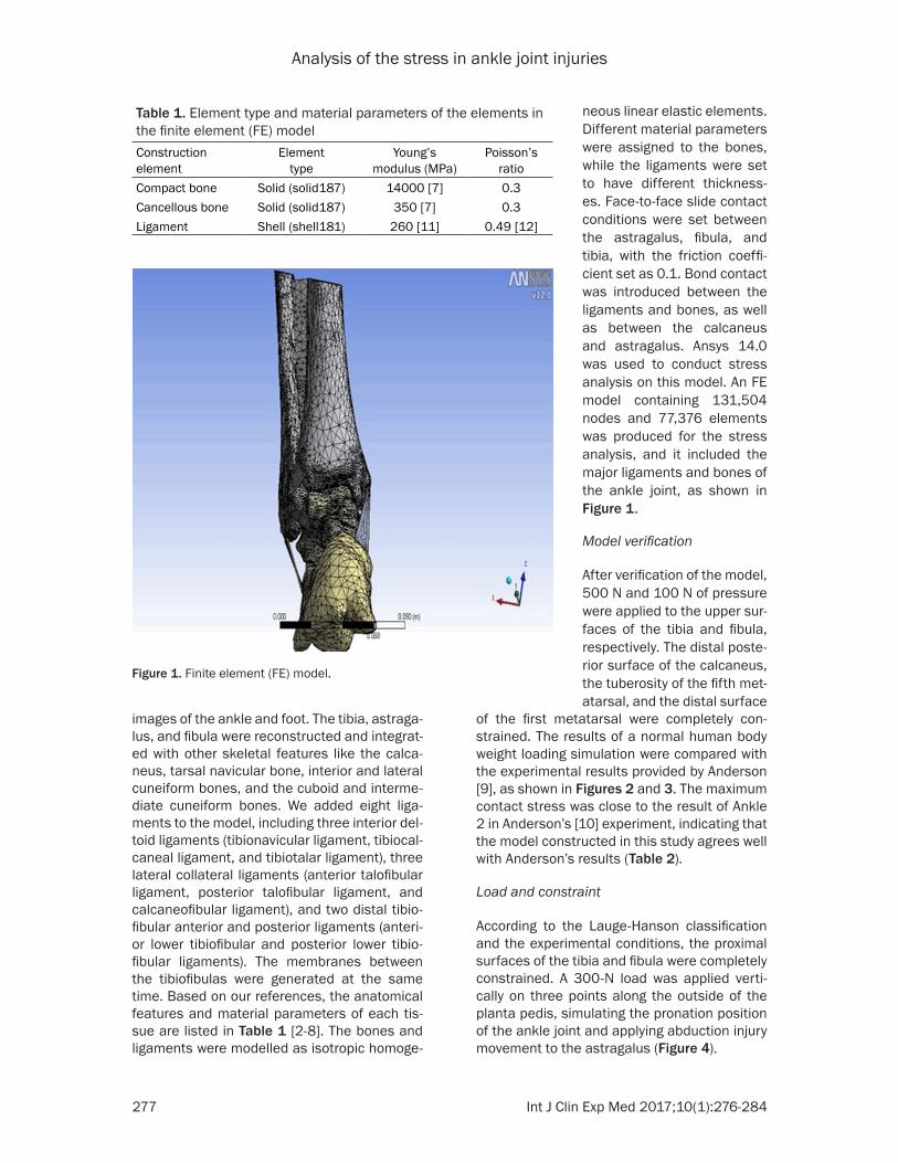
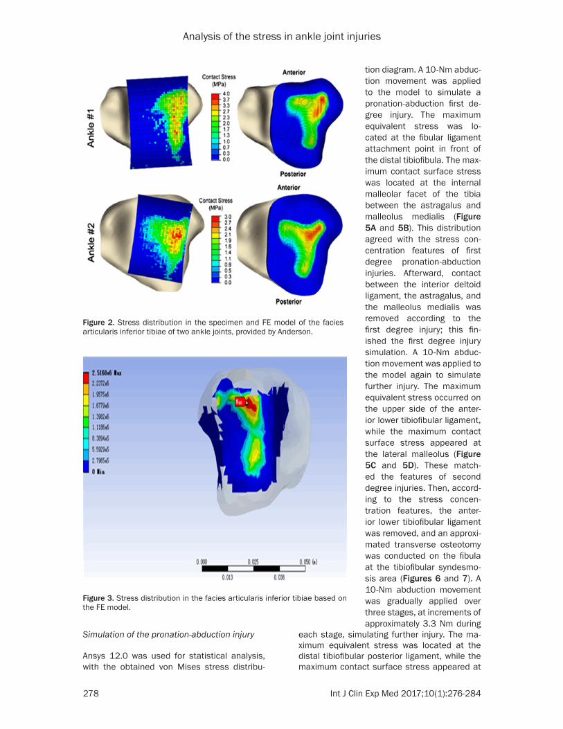
of the first metatarsal were completely con-strained The results of a normal human body weight loading simulation were compared with the experimental results provided by Anderson [9] as shown in Figures 2 and 3 The maximum contact stress was close to the result of Ankle 2 in Andersonrsquos [10] experiment indicating that the model constructed in this study agrees well with Andersonrsquos results (Table 2)
Load and constraint
According to the Lauge-Hanson classification and the experimental conditions the proximal surfaces of the tibia and fibula were completely constrained A 300-N load was applied verti-cally on three points along the outside of the planta pedis simulating the pronation position of the ankle joint and applying abduction injury movement to the astragalus (Figure 4)
Table 1 Element type and material parameters of the elements in the finite element (FE) modelConstruction element
Element type
Youngrsquos modulus (MPa)
Poissonrsquos ratio
Compact bone Solid (solid187) 14000 [7] 03Cancellous bone Solid (solid187) 350 [7] 03Ligament Shell (shell181) 260 [11] 049 [12]
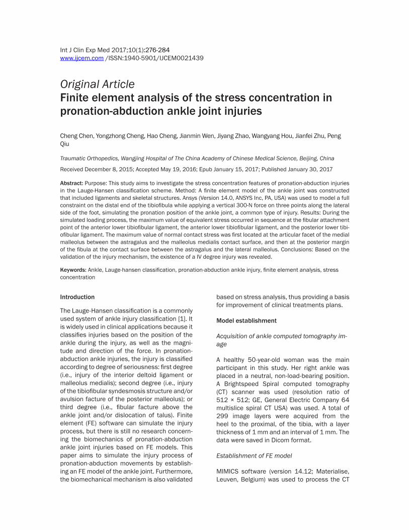
Figure 1 Finite element (FE) model
neous linear elastic elements Different material parameters were assigned to the bones while the ligaments were set to have different thickness- es Face-to-face slide contact conditions were set between the astragalus fibula and tibia with the friction coeffi-cient set as 01 Bond contact was introduced between the ligaments and bones as well as between the calcaneus and astragalus Ansys 140 was used to conduct stress analysis on this model An FE model containing 131504 nodes and 77376 elements was produced for the stress analysis and it included the major ligaments and bones of the ankle joint as shown in Figure 1
Model verification
After verification of the model 500 N and 100 N of pressure were applied to the upper sur-faces of the tibia and fibula respectively The distal poste-rior surface of the calcaneus the tuberosity of the fifth met-atarsal and the distal surface
Analysis of the stress in ankle joint injuries
278 Int J Clin Exp Med 201710(1)276-284
Simulation of the pronation-abduction injury
Ansys 120 was used for statistical analysis with the obtained von Mises stress distribu-
each stage simulating further injury The ma- ximum equivalent stress was located at the distal tibiofibular posterior ligament while the maximum contact surface stress appeared at
Figure 2 Stress distribution in the specimen and FE model of the facies articularis inferior tibiae of two ankle joints provided by Anderson
Figure 3 Stress distribution in the facies articularis inferior tibiae based on the FE model
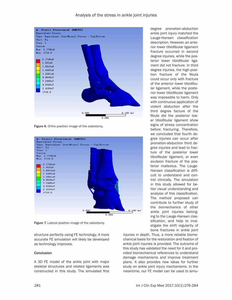
tion diagram A 10-Nm abduc-tion movement was applied to the model to simulate a pronation-abduction first de- gree injury The maximum equivalent stress was lo- cated at the fibular ligament attachment point in front of the distal tibiofibula The max-imum contact surface stress was located at the internal malleolar facet of the tibia between the astragalus and malleolus medialis (Figure 5A and 5B) This distribution agreed with the stress con-centration features of first degree pronation-abduction injuries Afterward contact between the interior deltoid ligament the astragalus and the malleolus medialis was removed according to the first degree injury this fin-ished the first degree injury simulation A 10-Nm abduc-tion movement was applied to the model again to simulate further injury The maximum equivalent stress occurred on the upper side of the anter- ior lower tibiofibular ligament while the maximum contact surface stress appeared at the lateral malleolus (Figure 5C and 5D) These match- ed the features of second degree injuries Then accord-ing to the stress concen- tration features the anter- ior lower tibiofibular ligament was removed and an approxi-mated transverse osteotomy was conducted on the fibula at the tibiofibular syndesmo-sis area (Figures 6 and 7) A 10-Nm abduction movement was gradually applied over three stages at increments of approximately 33 Nm during
Analysis of the stress in ankle joint injuries
279 Int J Clin Exp Med 201710(1)276-284
the posterior margin of the fibula at the contact surface between the astragalus and the lateral malleolus In addition the maximum equiva-lent stress increased as the load increased (Table 3 Figures 8 and 9) This matched the stress concentration feature of third degree injuries
Discussion
Simplification of the FE model of the ankle joint
To date no FE models have been constructed to simulate and analyze Lauge-Hansen prona-tion-abduction ankle injuries In this study an FE model with complete structures of the tibia fibula astragalus and related ligaments was constructed Because we mainly focused on the distribution and variation of stress in the
we modeled the ligaments using shell ele-ments The SHELL181 element is suitable for the analysis of shell structures with a certain thickness It is a four-node element with six degrees of freedom for each node (displace-ment freedom degrees in X Y Z directions and rotational freedom degrees around X Y Z axes) It can be used to analyze large rotational linear or nonlinear deformations The shell element can bear compression and tension as well as bending movements Hence it can favorably simulate thin-walled structures and is closer to actual human body ligaments than a bar ele-ment which is why we used it to model the eight major ligaments of the ankle joint
The numerical results of this study were com-pared with those of Andersonrsquos experimental study It was found that the contact surface pressure was almost the same in both scenari-
Table 2 Comparison between the results of the contact stress distribution in the facies articularis inferior tibiae obtained from Andersonrsquos experiment and this study
Anderson experimentThis studyAnkle 1 Ankle 2
Tekscan FE simulation Tekscan FE simulationMaximum contact stress (MPa) 369 374 292 274 252
Figure 4 Loading diagram of the simulated moment
tibia fibula and astragalus the model of calcaneus and surrounding foot bones were simplified According to Hui- skes et al [11] both the corti-cal bones and the cancell- ous bones can be consider- ed linear and isotropic ma- terials under static loading conditions
Advantages of using shell elements to simulate the ad-dition of ankle joint ligaments
Significant deviations exist among the material parame-ters reported by various stud-ies on ankle and foot liga-ments [12-15] Most of the studies used the bar element to establish their models [16-18] Liu Qinghua et al [19] used a spring element while Shin J et al [20] adopted a beam element In our study
Analysis of the stress in ankle joint injuries
280 Int J Clin Exp Med 201710(1)276-284
Figure 5 A Stress diagram of the ligament attachment point at the front tibiofibular syndesmosis where the maxi-mum equivalent stress exists B Stress diagram of the malleolus medialis where the maximum contact surface stress appears C Stress diagram of the upper side of the anterior lower tibiofibular ligament where the maximum equivalent stress is located D Stress diagram of the lateral malleolus which has the maximum contact surface stress
os indicating our model was valid and is appli-cable to mechanical analysis on pronation-abduction ankle joint injuries
Discovery of the pronation-abduction fourth degree injury
In this study stress concentration sites were found to occur in the anterior lower tibiofibular ligament after the first degree injury The equiv-alent stress in the anterior lower tibiofibular ligament reached the maximum value at the second degree injury However stress concen-tration occurred in the posterior lower tibiofibu-lar ligament only when the abduction force con-tinued after the third degree fibula fracture which is different from the description of the second degree injury in the Lauge-Hansen clas-
sification According to our study anterior lower tibiofibular ligament fractures occur in the sec-ond degree injury while no stress concentration or facture exists in the posterior lower tibiofibu-lar ligament After the third degree fibula frac-ture a stress concentration fracture occurs in the posterior lower tibiofibular ligament only when abduction force continues Therefore it is reasonable that fourth degree injuries may occur after pronation-abduction third degree injuries and could result in the fracture of the anterior lower tibiofibular ligament or the avul-sion fracture of the posterior malleolus
Even though the shell elements used in this study possess mechanical properties more similar to actual ligaments than other elements they are still unable to simulate the ligament
Analysis of the stress in ankle joint injuries
281 Int J Clin Exp Med 201710(1)276-284
structure perfectly using FE technology A more accurate FE simulation will likely be developed as technology improves
Conclusion
A 3D FE model of the ankle joint with major skeletal structures and related ligaments was constructed in this study The simulated first
injuries in depth Thus a more reliable biome-chanical basis for the restoration and fixation of ankle joint injuries is provided The outcome of this study has validated the need for it and pro-vided biomechanical references to understand damage mechanisms and improve treatment plans It also provides new ideas for further study on ankle joint injury mechanisms In the meantime our FE model can be used to simu-
Figure 6 Ortho position image of the osteotomy
Figure 7 Lateral position image of the osteotomy
degree pronation-abduction ankle joint injury matched the Lauge-Hansen classification description However an ante-rior lower tibiofibular ligament fracture occurred in second degree injuries while the pos-terior lower tibiofibular liga-ment did not fracture In third degree injuries the high-posi-tion fracture of the fibula could occur only with fracture of the anterior lower tibiofibu-lar ligament while the poste-rior lower tibiofibular ligament was impossible to harm Only with continuous application of violent abduction after the third degree facture of the fibula did the posterior low- er tibiofibular ligament show signs of stress concentration before fracturing Therefore we concluded that fourth de- gree injuries can occur after pronation-abduction third de- gree injuries and lead to frac-ture of the posterior lower tibiofibular ligament or even avulsion fracture of the pos- terior malleolus The Lauge-Hansen classification is diffi-cult to understand and con- trol clinically The simulation in this study allowed for be- tter visual understanding and analysis of this classification The method proposed can contribute to further study of the biomechanics of other ankle joint injuries belong- ing to the Lauge-Hansen clas-sification and help to inve- stigate the shift regularity of bone fractures in ankle joint
Analysis of the stress in ankle joint injuries
282 Int J Clin Exp Med 201710(1)276-284
Table 3 Distribution of stress and pressure in the pronation-abduction ankle joint injuryInjury degree Abduction load applied Value and position of the maximum equivalent stressMPa Value and position of the maximum contact surface stressMPaFirst degree 0-10 Nm The tibia attachment site of the anterior lower tibiofibular ligament
(3599 MPa)Interior articular surface of the malleolus medialis at the contact surface between the astragalus and malleolus medialis (527 MPa)
Second degree 0-10 Nm Upper side of the anterior lower tibiofibular ligament (3263 MPa) Posterior margin of the fibula at the contact surface between the astragalus and lateral malleolus (495 MPa)
Third degree One-third of the full load Posterior tibiofibular ligament (457 MPa) Posterior margin of the fibula at the contact surface between the astragalus and lateral malleolus (49 MPa)
Two-thirds of the full load Posterior tibiofibular ligament (702 MPa) Posterior margin of the fibula at the contact surface between the astragalus and lateral malleolus (52 MPa)
Full load Posterior tibiofibular ligament (940 MPa) Posterior margin of the fibula at the contact surface between the astragalus and lateral malleolus (54 MPa)
Analysis of the stress in ankle joint injuries
283 Int J Clin Exp Med 201710(1)276-284
Figure 8 Stress distribution in the posterior talofibular ligament after the abduction load was applied A Applying one-third of the full load B Applying two-thirds of the full load C Applying the full load
Figure 9 Stress distribution in the lateral malleolus after the abduction load was applied A Applying one-third of the full load B Applying two-thirds of the full load C Applying the full load
Analysis of the stress in ankle joint injuries
284 Int J Clin Exp Med 201710(1)276-284
late other injury mechanisms of the ankle joint and to review validate and investigate the occurrence of ankle diseases However taking the complexity of the ankle joint injury into con-sideration the construction of FE models for Lauge-Hanse pronation-abduction ankle joint injury still requires further investigation
Acknowledgements
The anatomical and biomechanical basis of the manual reduction mechanism of trimalleo-lar fractures based on the theory of tendon bundle bone (a project supported by the Na- tional Natural Science Foundation of China Grant No 81273785)
Disclosure of conflict of interest
None
Address correspondence to Dr Yongzhong Cheng Traumatic Orthopedics Wangjing Hospital of The China Academy of Chinese Medical Science Beijing China Tel 86 13810220180 Fax 861084739167 E-mail bless518139com
References
[1] Lauge-Hansen N Fracture of the ankle II Combined experimental surgical and experi-mental-roentgenologic investigations Arch Surg 1950 60 957-985
[2] Golanoacute P Vega J de Leeuw PA Malagelada F Manzanares MC Goumltzens V van Dijk CN Anatomy of the ankle ligaments a pictorial es-say Knee Surg Sports Traumatol Arthrosc 2010 18 557-569
[3] Siegler S Block J Schneck CD The mechani-cal characteristics of the collateral ligaments of the human ankle joint Foot Ankle 1988 8 234-242
[4] Chu TM Reddy NP Padovan J Three-dimensional finite element stress analysis of the polypropylene ankle-foot orthosis static-analysis Medical Eng Phys 1995 17 372-379
[5] Imhauser CW Siegler S Udupa JK Toy JR Subject-specific models of the hindfoot reveal a relationship between morphology and pas-sive mechanical properties J Biomech 2008 41 1341-1349
[6] Funk JR Hall GW Crandall JR Pilkey WD Linear and quasi-linear viscoelastic character-ization of ankle ligaments J Biomech Eng 2000 122 15-22
[7] Siegler S Block J Schneck CD The mechani-cal characteristics of the collateral ligaments of the human ankle joint Foot Ankle 1988 8 234-242
[8] Sarrafian S Anatomy of the foot and ankle de-scriptive topographic functional 2nd edition Philadelphia Lippincott Williams amp Wilkins 1993 pp 159-217
[9] Anderson DD Goldsworthy JK Li W James Rudert M Tochigi Y Brown TD Physical valida-tion of a patient-specific contact finite element J Biomech 2007 40 1662-1669
[10] Anderson DD Goldsworthy JK Li W James Rudert M Tochigi Y Brown TD Physical valida-tion of a patient-specific contact finite element model of the ankle J Biomech 2007 40 1662-1669
[11] Huiskes R On the modeling of long bones in structural analyses J Biomech 1982 15 65
[12] Haraguchi N Armiger RS Myerson MS Campbell JT Chao EY Prediction of three-di-mensional contact stress and ligament ten-sion in the ankle during stance determined from computational modeling Foot Ankle Int 2009 30 177-185
[13] Attarian DE McCrackin HJ DeVito DP McEl- haney JH Garrett WE Jr Biomechanical char-acteristics of human ankle ligaments Foot Ankle 1985 6 54-58
[14] Beumer A van Hemert WL Swierstra BA Jasper LE Belkoff SM A biomechanical evalu-ation of the tibiofibular and tibiotalar ligaments of the ankle Foot Ankle Int 2003 24 426-429
[15] Cheung JT An KN Zhang M Consequences of partial and total plantar fascia release a finite element study Foot Ankle Int 2006 27 125-132
[16] Cheung JT Zhang M Parametric design of pressure relieving foot orthosis using statis-tics-based finite element method Med Eng Phys 2008 30 269-277
[17] Brilakis E Kaselouris E Effects of foot posture on fifth metatarsalenspfractureensphealing aenspfi-niteenspelementenspstudy J FootenspAnkleenspSurg 2012 51 720-8
[18] Chen WP Ju CW Tang FT Effects of total con-tact insoles on the plantar stress redistribu-tion a finite element analysis Clin Biomech 2003 6 17-24
[19] Liu Q Zhang K Zhuang Y Li Z Yu B Pei G Analysis of the stress and displacement distri-bution of inferior tibiofibular syndesmosis inju-ries repaired with screw fixation a finite ele-ment study PLoS One 2013 3 8
[20] Shin J Untaroiu CD Biomechanical and injury response of human foot and ankle under com-plex loading J Biomech Eng 2013 135 101008
Analysis of the stress in ankle joint injuries
277 Int J Clin Exp Med 201710(1)276-284
images of the ankle and foot The tibia astraga-lus and fibula were reconstructed and integrat-ed with other skeletal features like the calca-neus tarsal navicular bone interior and lateral cuneiform bones and the cuboid and interme-diate cuneiform bones We added eight liga-ments to the model including three interior del-toid ligaments (tibionavicular ligament tibiocal-caneal ligament and tibiotalar ligament) three lateral collateral ligaments (anterior talofibular ligament posterior talofibular ligament and calcaneofibular ligament) and two distal tibio-fibular anterior and posterior ligaments (anteri-or lower tibiofibular and posterior lower tibio- fibular ligaments) The membranes between the tibiofibulas were generated at the same time Based on our references the anatomical features and material parameters of each tis-sue are listed in Table 1 [2-8] The bones and ligaments were modelled as isotropic homoge-
of the first metatarsal were completely con-strained The results of a normal human body weight loading simulation were compared with the experimental results provided by Anderson [9] as shown in Figures 2 and 3 The maximum contact stress was close to the result of Ankle 2 in Andersonrsquos [10] experiment indicating that the model constructed in this study agrees well with Andersonrsquos results (Table 2)
Load and constraint
According to the Lauge-Hanson classification and the experimental conditions the proximal surfaces of the tibia and fibula were completely constrained A 300-N load was applied verti-cally on three points along the outside of the planta pedis simulating the pronation position of the ankle joint and applying abduction injury movement to the astragalus (Figure 4)
Table 1 Element type and material parameters of the elements in the finite element (FE) modelConstruction element
Element type
Youngrsquos modulus (MPa)
Poissonrsquos ratio
Compact bone Solid (solid187) 14000 [7] 03Cancellous bone Solid (solid187) 350 [7] 03Ligament Shell (shell181) 260 [11] 049 [12]
Figure 1 Finite element (FE) model
neous linear elastic elements Different material parameters were assigned to the bones while the ligaments were set to have different thickness- es Face-to-face slide contact conditions were set between the astragalus fibula and tibia with the friction coeffi-cient set as 01 Bond contact was introduced between the ligaments and bones as well as between the calcaneus and astragalus Ansys 140 was used to conduct stress analysis on this model An FE model containing 131504 nodes and 77376 elements was produced for the stress analysis and it included the major ligaments and bones of the ankle joint as shown in Figure 1
Model verification
After verification of the model 500 N and 100 N of pressure were applied to the upper sur-faces of the tibia and fibula respectively The distal poste-rior surface of the calcaneus the tuberosity of the fifth met-atarsal and the distal surface
Analysis of the stress in ankle joint injuries
278 Int J Clin Exp Med 201710(1)276-284
Simulation of the pronation-abduction injury
Ansys 120 was used for statistical analysis with the obtained von Mises stress distribu-
each stage simulating further injury The ma- ximum equivalent stress was located at the distal tibiofibular posterior ligament while the maximum contact surface stress appeared at
Figure 2 Stress distribution in the specimen and FE model of the facies articularis inferior tibiae of two ankle joints provided by Anderson
Figure 3 Stress distribution in the facies articularis inferior tibiae based on the FE model
tion diagram A 10-Nm abduc-tion movement was applied to the model to simulate a pronation-abduction first de- gree injury The maximum equivalent stress was lo- cated at the fibular ligament attachment point in front of the distal tibiofibula The max-imum contact surface stress was located at the internal malleolar facet of the tibia between the astragalus and malleolus medialis (Figure 5A and 5B) This distribution agreed with the stress con-centration features of first degree pronation-abduction injuries Afterward contact between the interior deltoid ligament the astragalus and the malleolus medialis was removed according to the first degree injury this fin-ished the first degree injury simulation A 10-Nm abduc-tion movement was applied to the model again to simulate further injury The maximum equivalent stress occurred on the upper side of the anter- ior lower tibiofibular ligament while the maximum contact surface stress appeared at the lateral malleolus (Figure 5C and 5D) These match- ed the features of second degree injuries Then accord-ing to the stress concen- tration features the anter- ior lower tibiofibular ligament was removed and an approxi-mated transverse osteotomy was conducted on the fibula at the tibiofibular syndesmo-sis area (Figures 6 and 7) A 10-Nm abduction movement was gradually applied over three stages at increments of approximately 33 Nm during
Analysis of the stress in ankle joint injuries
279 Int J Clin Exp Med 201710(1)276-284
the posterior margin of the fibula at the contact surface between the astragalus and the lateral malleolus In addition the maximum equiva-lent stress increased as the load increased (Table 3 Figures 8 and 9) This matched the stress concentration feature of third degree injuries
Discussion
Simplification of the FE model of the ankle joint
To date no FE models have been constructed to simulate and analyze Lauge-Hansen prona-tion-abduction ankle injuries In this study an FE model with complete structures of the tibia fibula astragalus and related ligaments was constructed Because we mainly focused on the distribution and variation of stress in the
we modeled the ligaments using shell ele-ments The SHELL181 element is suitable for the analysis of shell structures with a certain thickness It is a four-node element with six degrees of freedom for each node (displace-ment freedom degrees in X Y Z directions and rotational freedom degrees around X Y Z axes) It can be used to analyze large rotational linear or nonlinear deformations The shell element can bear compression and tension as well as bending movements Hence it can favorably simulate thin-walled structures and is closer to actual human body ligaments than a bar ele-ment which is why we used it to model the eight major ligaments of the ankle joint
The numerical results of this study were com-pared with those of Andersonrsquos experimental study It was found that the contact surface pressure was almost the same in both scenari-
Table 2 Comparison between the results of the contact stress distribution in the facies articularis inferior tibiae obtained from Andersonrsquos experiment and this study
Anderson experimentThis studyAnkle 1 Ankle 2
Tekscan FE simulation Tekscan FE simulationMaximum contact stress (MPa) 369 374 292 274 252
Figure 4 Loading diagram of the simulated moment
tibia fibula and astragalus the model of calcaneus and surrounding foot bones were simplified According to Hui- skes et al [11] both the corti-cal bones and the cancell- ous bones can be consider- ed linear and isotropic ma- terials under static loading conditions
Advantages of using shell elements to simulate the ad-dition of ankle joint ligaments
Significant deviations exist among the material parame-ters reported by various stud-ies on ankle and foot liga-ments [12-15] Most of the studies used the bar element to establish their models [16-18] Liu Qinghua et al [19] used a spring element while Shin J et al [20] adopted a beam element In our study
Analysis of the stress in ankle joint injuries
280 Int J Clin Exp Med 201710(1)276-284
Figure 5 A Stress diagram of the ligament attachment point at the front tibiofibular syndesmosis where the maxi-mum equivalent stress exists B Stress diagram of the malleolus medialis where the maximum contact surface stress appears C Stress diagram of the upper side of the anterior lower tibiofibular ligament where the maximum equivalent stress is located D Stress diagram of the lateral malleolus which has the maximum contact surface stress
os indicating our model was valid and is appli-cable to mechanical analysis on pronation-abduction ankle joint injuries
Discovery of the pronation-abduction fourth degree injury
In this study stress concentration sites were found to occur in the anterior lower tibiofibular ligament after the first degree injury The equiv-alent stress in the anterior lower tibiofibular ligament reached the maximum value at the second degree injury However stress concen-tration occurred in the posterior lower tibiofibu-lar ligament only when the abduction force con-tinued after the third degree fibula fracture which is different from the description of the second degree injury in the Lauge-Hansen clas-
sification According to our study anterior lower tibiofibular ligament fractures occur in the sec-ond degree injury while no stress concentration or facture exists in the posterior lower tibiofibu-lar ligament After the third degree fibula frac-ture a stress concentration fracture occurs in the posterior lower tibiofibular ligament only when abduction force continues Therefore it is reasonable that fourth degree injuries may occur after pronation-abduction third degree injuries and could result in the fracture of the anterior lower tibiofibular ligament or the avul-sion fracture of the posterior malleolus
Even though the shell elements used in this study possess mechanical properties more similar to actual ligaments than other elements they are still unable to simulate the ligament
Analysis of the stress in ankle joint injuries
281 Int J Clin Exp Med 201710(1)276-284
structure perfectly using FE technology A more accurate FE simulation will likely be developed as technology improves
Conclusion
A 3D FE model of the ankle joint with major skeletal structures and related ligaments was constructed in this study The simulated first
injuries in depth Thus a more reliable biome-chanical basis for the restoration and fixation of ankle joint injuries is provided The outcome of this study has validated the need for it and pro-vided biomechanical references to understand damage mechanisms and improve treatment plans It also provides new ideas for further study on ankle joint injury mechanisms In the meantime our FE model can be used to simu-
Figure 6 Ortho position image of the osteotomy
Figure 7 Lateral position image of the osteotomy
degree pronation-abduction ankle joint injury matched the Lauge-Hansen classification description However an ante-rior lower tibiofibular ligament fracture occurred in second degree injuries while the pos-terior lower tibiofibular liga-ment did not fracture In third degree injuries the high-posi-tion fracture of the fibula could occur only with fracture of the anterior lower tibiofibu-lar ligament while the poste-rior lower tibiofibular ligament was impossible to harm Only with continuous application of violent abduction after the third degree facture of the fibula did the posterior low- er tibiofibular ligament show signs of stress concentration before fracturing Therefore we concluded that fourth de- gree injuries can occur after pronation-abduction third de- gree injuries and lead to frac-ture of the posterior lower tibiofibular ligament or even avulsion fracture of the pos- terior malleolus The Lauge-Hansen classification is diffi-cult to understand and con- trol clinically The simulation in this study allowed for be- tter visual understanding and analysis of this classification The method proposed can contribute to further study of the biomechanics of other ankle joint injuries belong- ing to the Lauge-Hansen clas-sification and help to inve- stigate the shift regularity of bone fractures in ankle joint
Analysis of the stress in ankle joint injuries
282 Int J Clin Exp Med 201710(1)276-284
Table 3 Distribution of stress and pressure in the pronation-abduction ankle joint injuryInjury degree Abduction load applied Value and position of the maximum equivalent stressMPa Value and position of the maximum contact surface stressMPaFirst degree 0-10 Nm The tibia attachment site of the anterior lower tibiofibular ligament
(3599 MPa)Interior articular surface of the malleolus medialis at the contact surface between the astragalus and malleolus medialis (527 MPa)
Second degree 0-10 Nm Upper side of the anterior lower tibiofibular ligament (3263 MPa) Posterior margin of the fibula at the contact surface between the astragalus and lateral malleolus (495 MPa)
Third degree One-third of the full load Posterior tibiofibular ligament (457 MPa) Posterior margin of the fibula at the contact surface between the astragalus and lateral malleolus (49 MPa)
Two-thirds of the full load Posterior tibiofibular ligament (702 MPa) Posterior margin of the fibula at the contact surface between the astragalus and lateral malleolus (52 MPa)
Full load Posterior tibiofibular ligament (940 MPa) Posterior margin of the fibula at the contact surface between the astragalus and lateral malleolus (54 MPa)
Analysis of the stress in ankle joint injuries
283 Int J Clin Exp Med 201710(1)276-284
Figure 8 Stress distribution in the posterior talofibular ligament after the abduction load was applied A Applying one-third of the full load B Applying two-thirds of the full load C Applying the full load
Figure 9 Stress distribution in the lateral malleolus after the abduction load was applied A Applying one-third of the full load B Applying two-thirds of the full load C Applying the full load
Analysis of the stress in ankle joint injuries
284 Int J Clin Exp Med 201710(1)276-284
late other injury mechanisms of the ankle joint and to review validate and investigate the occurrence of ankle diseases However taking the complexity of the ankle joint injury into con-sideration the construction of FE models for Lauge-Hanse pronation-abduction ankle joint injury still requires further investigation
Acknowledgements
The anatomical and biomechanical basis of the manual reduction mechanism of trimalleo-lar fractures based on the theory of tendon bundle bone (a project supported by the Na- tional Natural Science Foundation of China Grant No 81273785)
Disclosure of conflict of interest
None
Address correspondence to Dr Yongzhong Cheng Traumatic Orthopedics Wangjing Hospital of The China Academy of Chinese Medical Science Beijing China Tel 86 13810220180 Fax 861084739167 E-mail bless518139com
References
[1] Lauge-Hansen N Fracture of the ankle II Combined experimental surgical and experi-mental-roentgenologic investigations Arch Surg 1950 60 957-985
[2] Golanoacute P Vega J de Leeuw PA Malagelada F Manzanares MC Goumltzens V van Dijk CN Anatomy of the ankle ligaments a pictorial es-say Knee Surg Sports Traumatol Arthrosc 2010 18 557-569
[3] Siegler S Block J Schneck CD The mechani-cal characteristics of the collateral ligaments of the human ankle joint Foot Ankle 1988 8 234-242
[4] Chu TM Reddy NP Padovan J Three-dimensional finite element stress analysis of the polypropylene ankle-foot orthosis static-analysis Medical Eng Phys 1995 17 372-379
[5] Imhauser CW Siegler S Udupa JK Toy JR Subject-specific models of the hindfoot reveal a relationship between morphology and pas-sive mechanical properties J Biomech 2008 41 1341-1349
[6] Funk JR Hall GW Crandall JR Pilkey WD Linear and quasi-linear viscoelastic character-ization of ankle ligaments J Biomech Eng 2000 122 15-22
[7] Siegler S Block J Schneck CD The mechani-cal characteristics of the collateral ligaments of the human ankle joint Foot Ankle 1988 8 234-242
[8] Sarrafian S Anatomy of the foot and ankle de-scriptive topographic functional 2nd edition Philadelphia Lippincott Williams amp Wilkins 1993 pp 159-217
[9] Anderson DD Goldsworthy JK Li W James Rudert M Tochigi Y Brown TD Physical valida-tion of a patient-specific contact finite element J Biomech 2007 40 1662-1669
[10] Anderson DD Goldsworthy JK Li W James Rudert M Tochigi Y Brown TD Physical valida-tion of a patient-specific contact finite element model of the ankle J Biomech 2007 40 1662-1669
[11] Huiskes R On the modeling of long bones in structural analyses J Biomech 1982 15 65
[12] Haraguchi N Armiger RS Myerson MS Campbell JT Chao EY Prediction of three-di-mensional contact stress and ligament ten-sion in the ankle during stance determined from computational modeling Foot Ankle Int 2009 30 177-185
[13] Attarian DE McCrackin HJ DeVito DP McEl- haney JH Garrett WE Jr Biomechanical char-acteristics of human ankle ligaments Foot Ankle 1985 6 54-58
[14] Beumer A van Hemert WL Swierstra BA Jasper LE Belkoff SM A biomechanical evalu-ation of the tibiofibular and tibiotalar ligaments of the ankle Foot Ankle Int 2003 24 426-429
[15] Cheung JT An KN Zhang M Consequences of partial and total plantar fascia release a finite element study Foot Ankle Int 2006 27 125-132
[16] Cheung JT Zhang M Parametric design of pressure relieving foot orthosis using statis-tics-based finite element method Med Eng Phys 2008 30 269-277
[17] Brilakis E Kaselouris E Effects of foot posture on fifth metatarsalenspfractureensphealing aenspfi-niteenspelementenspstudy J FootenspAnkleenspSurg 2012 51 720-8
[18] Chen WP Ju CW Tang FT Effects of total con-tact insoles on the plantar stress redistribu-tion a finite element analysis Clin Biomech 2003 6 17-24
[19] Liu Q Zhang K Zhuang Y Li Z Yu B Pei G Analysis of the stress and displacement distri-bution of inferior tibiofibular syndesmosis inju-ries repaired with screw fixation a finite ele-ment study PLoS One 2013 3 8
[20] Shin J Untaroiu CD Biomechanical and injury response of human foot and ankle under com-plex loading J Biomech Eng 2013 135 101008
Analysis of the stress in ankle joint injuries
278 Int J Clin Exp Med 201710(1)276-284
Simulation of the pronation-abduction injury
Ansys 120 was used for statistical analysis with the obtained von Mises stress distribu-
each stage simulating further injury The ma- ximum equivalent stress was located at the distal tibiofibular posterior ligament while the maximum contact surface stress appeared at
Figure 2 Stress distribution in the specimen and FE model of the facies articularis inferior tibiae of two ankle joints provided by Anderson
Figure 3 Stress distribution in the facies articularis inferior tibiae based on the FE model
tion diagram A 10-Nm abduc-tion movement was applied to the model to simulate a pronation-abduction first de- gree injury The maximum equivalent stress was lo- cated at the fibular ligament attachment point in front of the distal tibiofibula The max-imum contact surface stress was located at the internal malleolar facet of the tibia between the astragalus and malleolus medialis (Figure 5A and 5B) This distribution agreed with the stress con-centration features of first degree pronation-abduction injuries Afterward contact between the interior deltoid ligament the astragalus and the malleolus medialis was removed according to the first degree injury this fin-ished the first degree injury simulation A 10-Nm abduc-tion movement was applied to the model again to simulate further injury The maximum equivalent stress occurred on the upper side of the anter- ior lower tibiofibular ligament while the maximum contact surface stress appeared at the lateral malleolus (Figure 5C and 5D) These match- ed the features of second degree injuries Then accord-ing to the stress concen- tration features the anter- ior lower tibiofibular ligament was removed and an approxi-mated transverse osteotomy was conducted on the fibula at the tibiofibular syndesmo-sis area (Figures 6 and 7) A 10-Nm abduction movement was gradually applied over three stages at increments of approximately 33 Nm during
Analysis of the stress in ankle joint injuries
279 Int J Clin Exp Med 201710(1)276-284
the posterior margin of the fibula at the contact surface between the astragalus and the lateral malleolus In addition the maximum equiva-lent stress increased as the load increased (Table 3 Figures 8 and 9) This matched the stress concentration feature of third degree injuries
Discussion
Simplification of the FE model of the ankle joint
To date no FE models have been constructed to simulate and analyze Lauge-Hansen prona-tion-abduction ankle injuries In this study an FE model with complete structures of the tibia fibula astragalus and related ligaments was constructed Because we mainly focused on the distribution and variation of stress in the
we modeled the ligaments using shell ele-ments The SHELL181 element is suitable for the analysis of shell structures with a certain thickness It is a four-node element with six degrees of freedom for each node (displace-ment freedom degrees in X Y Z directions and rotational freedom degrees around X Y Z axes) It can be used to analyze large rotational linear or nonlinear deformations The shell element can bear compression and tension as well as bending movements Hence it can favorably simulate thin-walled structures and is closer to actual human body ligaments than a bar ele-ment which is why we used it to model the eight major ligaments of the ankle joint
The numerical results of this study were com-pared with those of Andersonrsquos experimental study It was found that the contact surface pressure was almost the same in both scenari-
Table 2 Comparison between the results of the contact stress distribution in the facies articularis inferior tibiae obtained from Andersonrsquos experiment and this study
Anderson experimentThis studyAnkle 1 Ankle 2
Tekscan FE simulation Tekscan FE simulationMaximum contact stress (MPa) 369 374 292 274 252
Figure 4 Loading diagram of the simulated moment
tibia fibula and astragalus the model of calcaneus and surrounding foot bones were simplified According to Hui- skes et al [11] both the corti-cal bones and the cancell- ous bones can be consider- ed linear and isotropic ma- terials under static loading conditions
Advantages of using shell elements to simulate the ad-dition of ankle joint ligaments
Significant deviations exist among the material parame-ters reported by various stud-ies on ankle and foot liga-ments [12-15] Most of the studies used the bar element to establish their models [16-18] Liu Qinghua et al [19] used a spring element while Shin J et al [20] adopted a beam element In our study
Analysis of the stress in ankle joint injuries
280 Int J Clin Exp Med 201710(1)276-284
Figure 5 A Stress diagram of the ligament attachment point at the front tibiofibular syndesmosis where the maxi-mum equivalent stress exists B Stress diagram of the malleolus medialis where the maximum contact surface stress appears C Stress diagram of the upper side of the anterior lower tibiofibular ligament where the maximum equivalent stress is located D Stress diagram of the lateral malleolus which has the maximum contact surface stress
os indicating our model was valid and is appli-cable to mechanical analysis on pronation-abduction ankle joint injuries
Discovery of the pronation-abduction fourth degree injury
In this study stress concentration sites were found to occur in the anterior lower tibiofibular ligament after the first degree injury The equiv-alent stress in the anterior lower tibiofibular ligament reached the maximum value at the second degree injury However stress concen-tration occurred in the posterior lower tibiofibu-lar ligament only when the abduction force con-tinued after the third degree fibula fracture which is different from the description of the second degree injury in the Lauge-Hansen clas-
sification According to our study anterior lower tibiofibular ligament fractures occur in the sec-ond degree injury while no stress concentration or facture exists in the posterior lower tibiofibu-lar ligament After the third degree fibula frac-ture a stress concentration fracture occurs in the posterior lower tibiofibular ligament only when abduction force continues Therefore it is reasonable that fourth degree injuries may occur after pronation-abduction third degree injuries and could result in the fracture of the anterior lower tibiofibular ligament or the avul-sion fracture of the posterior malleolus
Even though the shell elements used in this study possess mechanical properties more similar to actual ligaments than other elements they are still unable to simulate the ligament
Analysis of the stress in ankle joint injuries
281 Int J Clin Exp Med 201710(1)276-284
structure perfectly using FE technology A more accurate FE simulation will likely be developed as technology improves
Conclusion
A 3D FE model of the ankle joint with major skeletal structures and related ligaments was constructed in this study The simulated first
injuries in depth Thus a more reliable biome-chanical basis for the restoration and fixation of ankle joint injuries is provided The outcome of this study has validated the need for it and pro-vided biomechanical references to understand damage mechanisms and improve treatment plans It also provides new ideas for further study on ankle joint injury mechanisms In the meantime our FE model can be used to simu-
Figure 6 Ortho position image of the osteotomy
Figure 7 Lateral position image of the osteotomy
degree pronation-abduction ankle joint injury matched the Lauge-Hansen classification description However an ante-rior lower tibiofibular ligament fracture occurred in second degree injuries while the pos-terior lower tibiofibular liga-ment did not fracture In third degree injuries the high-posi-tion fracture of the fibula could occur only with fracture of the anterior lower tibiofibu-lar ligament while the poste-rior lower tibiofibular ligament was impossible to harm Only with continuous application of violent abduction after the third degree facture of the fibula did the posterior low- er tibiofibular ligament show signs of stress concentration before fracturing Therefore we concluded that fourth de- gree injuries can occur after pronation-abduction third de- gree injuries and lead to frac-ture of the posterior lower tibiofibular ligament or even avulsion fracture of the pos- terior malleolus The Lauge-Hansen classification is diffi-cult to understand and con- trol clinically The simulation in this study allowed for be- tter visual understanding and analysis of this classification The method proposed can contribute to further study of the biomechanics of other ankle joint injuries belong- ing to the Lauge-Hansen clas-sification and help to inve- stigate the shift regularity of bone fractures in ankle joint
Analysis of the stress in ankle joint injuries
282 Int J Clin Exp Med 201710(1)276-284
Table 3 Distribution of stress and pressure in the pronation-abduction ankle joint injuryInjury degree Abduction load applied Value and position of the maximum equivalent stressMPa Value and position of the maximum contact surface stressMPaFirst degree 0-10 Nm The tibia attachment site of the anterior lower tibiofibular ligament
(3599 MPa)Interior articular surface of the malleolus medialis at the contact surface between the astragalus and malleolus medialis (527 MPa)
Second degree 0-10 Nm Upper side of the anterior lower tibiofibular ligament (3263 MPa) Posterior margin of the fibula at the contact surface between the astragalus and lateral malleolus (495 MPa)
Third degree One-third of the full load Posterior tibiofibular ligament (457 MPa) Posterior margin of the fibula at the contact surface between the astragalus and lateral malleolus (49 MPa)
Two-thirds of the full load Posterior tibiofibular ligament (702 MPa) Posterior margin of the fibula at the contact surface between the astragalus and lateral malleolus (52 MPa)
Full load Posterior tibiofibular ligament (940 MPa) Posterior margin of the fibula at the contact surface between the astragalus and lateral malleolus (54 MPa)
Analysis of the stress in ankle joint injuries
283 Int J Clin Exp Med 201710(1)276-284
Figure 8 Stress distribution in the posterior talofibular ligament after the abduction load was applied A Applying one-third of the full load B Applying two-thirds of the full load C Applying the full load
Figure 9 Stress distribution in the lateral malleolus after the abduction load was applied A Applying one-third of the full load B Applying two-thirds of the full load C Applying the full load
Analysis of the stress in ankle joint injuries
284 Int J Clin Exp Med 201710(1)276-284
late other injury mechanisms of the ankle joint and to review validate and investigate the occurrence of ankle diseases However taking the complexity of the ankle joint injury into con-sideration the construction of FE models for Lauge-Hanse pronation-abduction ankle joint injury still requires further investigation
Acknowledgements
The anatomical and biomechanical basis of the manual reduction mechanism of trimalleo-lar fractures based on the theory of tendon bundle bone (a project supported by the Na- tional Natural Science Foundation of China Grant No 81273785)
Disclosure of conflict of interest
None
Address correspondence to Dr Yongzhong Cheng Traumatic Orthopedics Wangjing Hospital of The China Academy of Chinese Medical Science Beijing China Tel 86 13810220180 Fax 861084739167 E-mail bless518139com
References
[1] Lauge-Hansen N Fracture of the ankle II Combined experimental surgical and experi-mental-roentgenologic investigations Arch Surg 1950 60 957-985
[2] Golanoacute P Vega J de Leeuw PA Malagelada F Manzanares MC Goumltzens V van Dijk CN Anatomy of the ankle ligaments a pictorial es-say Knee Surg Sports Traumatol Arthrosc 2010 18 557-569
[3] Siegler S Block J Schneck CD The mechani-cal characteristics of the collateral ligaments of the human ankle joint Foot Ankle 1988 8 234-242
[4] Chu TM Reddy NP Padovan J Three-dimensional finite element stress analysis of the polypropylene ankle-foot orthosis static-analysis Medical Eng Phys 1995 17 372-379
[5] Imhauser CW Siegler S Udupa JK Toy JR Subject-specific models of the hindfoot reveal a relationship between morphology and pas-sive mechanical properties J Biomech 2008 41 1341-1349
[6] Funk JR Hall GW Crandall JR Pilkey WD Linear and quasi-linear viscoelastic character-ization of ankle ligaments J Biomech Eng 2000 122 15-22
[7] Siegler S Block J Schneck CD The mechani-cal characteristics of the collateral ligaments of the human ankle joint Foot Ankle 1988 8 234-242
[8] Sarrafian S Anatomy of the foot and ankle de-scriptive topographic functional 2nd edition Philadelphia Lippincott Williams amp Wilkins 1993 pp 159-217
[9] Anderson DD Goldsworthy JK Li W James Rudert M Tochigi Y Brown TD Physical valida-tion of a patient-specific contact finite element J Biomech 2007 40 1662-1669
[10] Anderson DD Goldsworthy JK Li W James Rudert M Tochigi Y Brown TD Physical valida-tion of a patient-specific contact finite element model of the ankle J Biomech 2007 40 1662-1669
[11] Huiskes R On the modeling of long bones in structural analyses J Biomech 1982 15 65
[12] Haraguchi N Armiger RS Myerson MS Campbell JT Chao EY Prediction of three-di-mensional contact stress and ligament ten-sion in the ankle during stance determined from computational modeling Foot Ankle Int 2009 30 177-185
[13] Attarian DE McCrackin HJ DeVito DP McEl- haney JH Garrett WE Jr Biomechanical char-acteristics of human ankle ligaments Foot Ankle 1985 6 54-58
[14] Beumer A van Hemert WL Swierstra BA Jasper LE Belkoff SM A biomechanical evalu-ation of the tibiofibular and tibiotalar ligaments of the ankle Foot Ankle Int 2003 24 426-429
[15] Cheung JT An KN Zhang M Consequences of partial and total plantar fascia release a finite element study Foot Ankle Int 2006 27 125-132
[16] Cheung JT Zhang M Parametric design of pressure relieving foot orthosis using statis-tics-based finite element method Med Eng Phys 2008 30 269-277
[17] Brilakis E Kaselouris E Effects of foot posture on fifth metatarsalenspfractureensphealing aenspfi-niteenspelementenspstudy J FootenspAnkleenspSurg 2012 51 720-8
[18] Chen WP Ju CW Tang FT Effects of total con-tact insoles on the plantar stress redistribu-tion a finite element analysis Clin Biomech 2003 6 17-24
[19] Liu Q Zhang K Zhuang Y Li Z Yu B Pei G Analysis of the stress and displacement distri-bution of inferior tibiofibular syndesmosis inju-ries repaired with screw fixation a finite ele-ment study PLoS One 2013 3 8
[20] Shin J Untaroiu CD Biomechanical and injury response of human foot and ankle under com-plex loading J Biomech Eng 2013 135 101008

Analysis of the stress in ankle joint injuries
280 Int J Clin Exp Med 201710(1)276-284
Figure 5 A Stress diagram of the ligament attachment point at the front tibiofibular syndesmosis where the maxi-mum equivalent stress exists B Stress diagram of the malleolus medialis where the maximum contact surface stress appears C Stress diagram of the upper side of the anterior lower tibiofibular ligament where the maximum equivalent stress is located D Stress diagram of the lateral malleolus which has the maximum contact surface stress
os indicating our model was valid and is appli-cable to mechanical analysis on pronation-abduction ankle joint injuries
Discovery of the pronation-abduction fourth degree injury
In this study stress concentration sites were found to occur in the anterior lower tibiofibular ligament after the first degree injury The equiv-alent stress in the anterior lower tibiofibular ligament reached the maximum value at the second degree injury However stress concen-tration occurred in the posterior lower tibiofibu-lar ligament only when the abduction force con-tinued after the third degree fibula fracture which is different from the description of the second degree injury in the Lauge-Hansen clas-
sification According to our study anterior lower tibiofibular ligament fractures occur in the sec-ond degree injury while no stress concentration or facture exists in the posterior lower tibiofibu-lar ligament After the third degree fibula frac-ture a stress concentration fracture occurs in the posterior lower tibiofibular ligament only when abduction force continues Therefore it is reasonable that fourth degree injuries may occur after pronation-abduction third degree injuries and could result in the fracture of the anterior lower tibiofibular ligament or the avul-sion fracture of the posterior malleolus
Even though the shell elements used in this study possess mechanical properties more similar to actual ligaments than other elements they are still unable to simulate the ligament
Analysis of the stress in ankle joint injuries
281 Int J Clin Exp Med 201710(1)276-284
structure perfectly using FE technology A more accurate FE simulation will likely be developed as technology improves
Conclusion
A 3D FE model of the ankle joint with major skeletal structures and related ligaments was constructed in this study The simulated first
injuries in depth Thus a more reliable biome-chanical basis for the restoration and fixation of ankle joint injuries is provided The outcome of this study has validated the need for it and pro-vided biomechanical references to understand damage mechanisms and improve treatment plans It also provides new ideas for further study on ankle joint injury mechanisms In the meantime our FE model can be used to simu-
Figure 6 Ortho position image of the osteotomy
Figure 7 Lateral position image of the osteotomy
degree pronation-abduction ankle joint injury matched the Lauge-Hansen classification description However an ante-rior lower tibiofibular ligament fracture occurred in second degree injuries while the pos-terior lower tibiofibular liga-ment did not fracture In third degree injuries the high-posi-tion fracture of the fibula could occur only with fracture of the anterior lower tibiofibu-lar ligament while the poste-rior lower tibiofibular ligament was impossible to harm Only with continuous application of violent abduction after the third degree facture of the fibula did the posterior low- er tibiofibular ligament show signs of stress concentration before fracturing Therefore we concluded that fourth de- gree injuries can occur after pronation-abduction third de- gree injuries and lead to frac-ture of the posterior lower tibiofibular ligament or even avulsion fracture of the pos- terior malleolus The Lauge-Hansen classification is diffi-cult to understand and con- trol clinically The simulation in this study allowed for be- tter visual understanding and analysis of this classification The method proposed can contribute to further study of the biomechanics of other ankle joint injuries belong- ing to the Lauge-Hansen clas-sification and help to inve- stigate the shift regularity of bone fractures in ankle joint
Analysis of the stress in ankle joint injuries
282 Int J Clin Exp Med 201710(1)276-284
Table 3 Distribution of stress and pressure in the pronation-abduction ankle joint injuryInjury degree Abduction load applied Value and position of the maximum equivalent stressMPa Value and position of the maximum contact surface stressMPaFirst degree 0-10 Nm The tibia attachment site of the anterior lower tibiofibular ligament
(3599 MPa)Interior articular surface of the malleolus medialis at the contact surface between the astragalus and malleolus medialis (527 MPa)
Second degree 0-10 Nm Upper side of the anterior lower tibiofibular ligament (3263 MPa) Posterior margin of the fibula at the contact surface between the astragalus and lateral malleolus (495 MPa)
Third degree One-third of the full load Posterior tibiofibular ligament (457 MPa) Posterior margin of the fibula at the contact surface between the astragalus and lateral malleolus (49 MPa)
Two-thirds of the full load Posterior tibiofibular ligament (702 MPa) Posterior margin of the fibula at the contact surface between the astragalus and lateral malleolus (52 MPa)
Full load Posterior tibiofibular ligament (940 MPa) Posterior margin of the fibula at the contact surface between the astragalus and lateral malleolus (54 MPa)
Analysis of the stress in ankle joint injuries
283 Int J Clin Exp Med 201710(1)276-284
Figure 8 Stress distribution in the posterior talofibular ligament after the abduction load was applied A Applying one-third of the full load B Applying two-thirds of the full load C Applying the full load
Figure 9 Stress distribution in the lateral malleolus after the abduction load was applied A Applying one-third of the full load B Applying two-thirds of the full load C Applying the full load
Analysis of the stress in ankle joint injuries
284 Int J Clin Exp Med 201710(1)276-284
late other injury mechanisms of the ankle joint and to review validate and investigate the occurrence of ankle diseases However taking the complexity of the ankle joint injury into con-sideration the construction of FE models for Lauge-Hanse pronation-abduction ankle joint injury still requires further investigation
Acknowledgements
The anatomical and biomechanical basis of the manual reduction mechanism of trimalleo-lar fractures based on the theory of tendon bundle bone (a project supported by the Na- tional Natural Science Foundation of China Grant No 81273785)
Disclosure of conflict of interest
None
Address correspondence to Dr Yongzhong Cheng Traumatic Orthopedics Wangjing Hospital of The China Academy of Chinese Medical Science Beijing China Tel 86 13810220180 Fax 861084739167 E-mail bless518139com
References
[1] Lauge-Hansen N Fracture of the ankle II Combined experimental surgical and experi-mental-roentgenologic investigations Arch Surg 1950 60 957-985
[2] Golanoacute P Vega J de Leeuw PA Malagelada F Manzanares MC Goumltzens V van Dijk CN Anatomy of the ankle ligaments a pictorial es-say Knee Surg Sports Traumatol Arthrosc 2010 18 557-569
[3] Siegler S Block J Schneck CD The mechani-cal characteristics of the collateral ligaments of the human ankle joint Foot Ankle 1988 8 234-242
[4] Chu TM Reddy NP Padovan J Three-dimensional finite element stress analysis of the polypropylene ankle-foot orthosis static-analysis Medical Eng Phys 1995 17 372-379
[5] Imhauser CW Siegler S Udupa JK Toy JR Subject-specific models of the hindfoot reveal a relationship between morphology and pas-sive mechanical properties J Biomech 2008 41 1341-1349
[6] Funk JR Hall GW Crandall JR Pilkey WD Linear and quasi-linear viscoelastic character-ization of ankle ligaments J Biomech Eng 2000 122 15-22
[7] Siegler S Block J Schneck CD The mechani-cal characteristics of the collateral ligaments of the human ankle joint Foot Ankle 1988 8 234-242
[8] Sarrafian S Anatomy of the foot and ankle de-scriptive topographic functional 2nd edition Philadelphia Lippincott Williams amp Wilkins 1993 pp 159-217
[9] Anderson DD Goldsworthy JK Li W James Rudert M Tochigi Y Brown TD Physical valida-tion of a patient-specific contact finite element J Biomech 2007 40 1662-1669
[10] Anderson DD Goldsworthy JK Li W James Rudert M Tochigi Y Brown TD Physical valida-tion of a patient-specific contact finite element model of the ankle J Biomech 2007 40 1662-1669
[11] Huiskes R On the modeling of long bones in structural analyses J Biomech 1982 15 65
[12] Haraguchi N Armiger RS Myerson MS Campbell JT Chao EY Prediction of three-di-mensional contact stress and ligament ten-sion in the ankle during stance determined from computational modeling Foot Ankle Int 2009 30 177-185
[13] Attarian DE McCrackin HJ DeVito DP McEl- haney JH Garrett WE Jr Biomechanical char-acteristics of human ankle ligaments Foot Ankle 1985 6 54-58
[14] Beumer A van Hemert WL Swierstra BA Jasper LE Belkoff SM A biomechanical evalu-ation of the tibiofibular and tibiotalar ligaments of the ankle Foot Ankle Int 2003 24 426-429
[15] Cheung JT An KN Zhang M Consequences of partial and total plantar fascia release a finite element study Foot Ankle Int 2006 27 125-132
[16] Cheung JT Zhang M Parametric design of pressure relieving foot orthosis using statis-tics-based finite element method Med Eng Phys 2008 30 269-277
[17] Brilakis E Kaselouris E Effects of foot posture on fifth metatarsalenspfractureensphealing aenspfi-niteenspelementenspstudy J FootenspAnkleenspSurg 2012 51 720-8
[18] Chen WP Ju CW Tang FT Effects of total con-tact insoles on the plantar stress redistribu-tion a finite element analysis Clin Biomech 2003 6 17-24
[19] Liu Q Zhang K Zhuang Y Li Z Yu B Pei G Analysis of the stress and displacement distri-bution of inferior tibiofibular syndesmosis inju-ries repaired with screw fixation a finite ele-ment study PLoS One 2013 3 8
[20] Shin J Untaroiu CD Biomechanical and injury response of human foot and ankle under com-plex loading J Biomech Eng 2013 135 101008
Analysis of the stress in ankle joint injuries
281 Int J Clin Exp Med 201710(1)276-284
structure perfectly using FE technology A more accurate FE simulation will likely be developed as technology improves
Conclusion
A 3D FE model of the ankle joint with major skeletal structures and related ligaments was constructed in this study The simulated first
injuries in depth Thus a more reliable biome-chanical basis for the restoration and fixation of ankle joint injuries is provided The outcome of this study has validated the need for it and pro-vided biomechanical references to understand damage mechanisms and improve treatment plans It also provides new ideas for further study on ankle joint injury mechanisms In the meantime our FE model can be used to simu-
Figure 6 Ortho position image of the osteotomy
Figure 7 Lateral position image of the osteotomy
degree pronation-abduction ankle joint injury matched the Lauge-Hansen classification description However an ante-rior lower tibiofibular ligament fracture occurred in second degree injuries while the pos-terior lower tibiofibular liga-ment did not fracture In third degree injuries the high-posi-tion fracture of the fibula could occur only with fracture of the anterior lower tibiofibu-lar ligament while the poste-rior lower tibiofibular ligament was impossible to harm Only with continuous application of violent abduction after the third degree facture of the fibula did the posterior low- er tibiofibular ligament show signs of stress concentration before fracturing Therefore we concluded that fourth de- gree injuries can occur after pronation-abduction third de- gree injuries and lead to frac-ture of the posterior lower tibiofibular ligament or even avulsion fracture of the pos- terior malleolus The Lauge-Hansen classification is diffi-cult to understand and con- trol clinically The simulation in this study allowed for be- tter visual understanding and analysis of this classification The method proposed can contribute to further study of the biomechanics of other ankle joint injuries belong- ing to the Lauge-Hansen clas-sification and help to inve- stigate the shift regularity of bone fractures in ankle joint
Analysis of the stress in ankle joint injuries
282 Int J Clin Exp Med 201710(1)276-284
Table 3 Distribution of stress and pressure in the pronation-abduction ankle joint injuryInjury degree Abduction load applied Value and position of the maximum equivalent stressMPa Value and position of the maximum contact surface stressMPaFirst degree 0-10 Nm The tibia attachment site of the anterior lower tibiofibular ligament
(3599 MPa)Interior articular surface of the malleolus medialis at the contact surface between the astragalus and malleolus medialis (527 MPa)
Second degree 0-10 Nm Upper side of the anterior lower tibiofibular ligament (3263 MPa) Posterior margin of the fibula at the contact surface between the astragalus and lateral malleolus (495 MPa)
Third degree One-third of the full load Posterior tibiofibular ligament (457 MPa) Posterior margin of the fibula at the contact surface between the astragalus and lateral malleolus (49 MPa)
Two-thirds of the full load Posterior tibiofibular ligament (702 MPa) Posterior margin of the fibula at the contact surface between the astragalus and lateral malleolus (52 MPa)
Full load Posterior tibiofibular ligament (940 MPa) Posterior margin of the fibula at the contact surface between the astragalus and lateral malleolus (54 MPa)
Analysis of the stress in ankle joint injuries
283 Int J Clin Exp Med 201710(1)276-284
Figure 8 Stress distribution in the posterior talofibular ligament after the abduction load was applied A Applying one-third of the full load B Applying two-thirds of the full load C Applying the full load
Figure 9 Stress distribution in the lateral malleolus after the abduction load was applied A Applying one-third of the full load B Applying two-thirds of the full load C Applying the full load
Analysis of the stress in ankle joint injuries
284 Int J Clin Exp Med 201710(1)276-284
late other injury mechanisms of the ankle joint and to review validate and investigate the occurrence of ankle diseases However taking the complexity of the ankle joint injury into con-sideration the construction of FE models for Lauge-Hanse pronation-abduction ankle joint injury still requires further investigation
Acknowledgements
The anatomical and biomechanical basis of the manual reduction mechanism of trimalleo-lar fractures based on the theory of tendon bundle bone (a project supported by the Na- tional Natural Science Foundation of China Grant No 81273785)
Disclosure of conflict of interest
None
Address correspondence to Dr Yongzhong Cheng Traumatic Orthopedics Wangjing Hospital of The China Academy of Chinese Medical Science Beijing China Tel 86 13810220180 Fax 861084739167 E-mail bless518139com
References
[1] Lauge-Hansen N Fracture of the ankle II Combined experimental surgical and experi-mental-roentgenologic investigations Arch Surg 1950 60 957-985
[2] Golanoacute P Vega J de Leeuw PA Malagelada F Manzanares MC Goumltzens V van Dijk CN Anatomy of the ankle ligaments a pictorial es-say Knee Surg Sports Traumatol Arthrosc 2010 18 557-569
[3] Siegler S Block J Schneck CD The mechani-cal characteristics of the collateral ligaments of the human ankle joint Foot Ankle 1988 8 234-242
[4] Chu TM Reddy NP Padovan J Three-dimensional finite element stress analysis of the polypropylene ankle-foot orthosis static-analysis Medical Eng Phys 1995 17 372-379
[5] Imhauser CW Siegler S Udupa JK Toy JR Subject-specific models of the hindfoot reveal a relationship between morphology and pas-sive mechanical properties J Biomech 2008 41 1341-1349
[6] Funk JR Hall GW Crandall JR Pilkey WD Linear and quasi-linear viscoelastic character-ization of ankle ligaments J Biomech Eng 2000 122 15-22
[7] Siegler S Block J Schneck CD The mechani-cal characteristics of the collateral ligaments of the human ankle joint Foot Ankle 1988 8 234-242
[8] Sarrafian S Anatomy of the foot and ankle de-scriptive topographic functional 2nd edition Philadelphia Lippincott Williams amp Wilkins 1993 pp 159-217
[9] Anderson DD Goldsworthy JK Li W James Rudert M Tochigi Y Brown TD Physical valida-tion of a patient-specific contact finite element J Biomech 2007 40 1662-1669
[10] Anderson DD Goldsworthy JK Li W James Rudert M Tochigi Y Brown TD Physical valida-tion of a patient-specific contact finite element model of the ankle J Biomech 2007 40 1662-1669
[11] Huiskes R On the modeling of long bones in structural analyses J Biomech 1982 15 65
[12] Haraguchi N Armiger RS Myerson MS Campbell JT Chao EY Prediction of three-di-mensional contact stress and ligament ten-sion in the ankle during stance determined from computational modeling Foot Ankle Int 2009 30 177-185
[13] Attarian DE McCrackin HJ DeVito DP McEl- haney JH Garrett WE Jr Biomechanical char-acteristics of human ankle ligaments Foot Ankle 1985 6 54-58
[14] Beumer A van Hemert WL Swierstra BA Jasper LE Belkoff SM A biomechanical evalu-ation of the tibiofibular and tibiotalar ligaments of the ankle Foot Ankle Int 2003 24 426-429
[15] Cheung JT An KN Zhang M Consequences of partial and total plantar fascia release a finite element study Foot Ankle Int 2006 27 125-132
[16] Cheung JT Zhang M Parametric design of pressure relieving foot orthosis using statis-tics-based finite element method Med Eng Phys 2008 30 269-277
[17] Brilakis E Kaselouris E Effects of foot posture on fifth metatarsalenspfractureensphealing aenspfi-niteenspelementenspstudy J FootenspAnkleenspSurg 2012 51 720-8
[18] Chen WP Ju CW Tang FT Effects of total con-tact insoles on the plantar stress redistribu-tion a finite element analysis Clin Biomech 2003 6 17-24
[19] Liu Q Zhang K Zhuang Y Li Z Yu B Pei G Analysis of the stress and displacement distri-bution of inferior tibiofibular syndesmosis inju-ries repaired with screw fixation a finite ele-ment study PLoS One 2013 3 8
[20] Shin J Untaroiu CD Biomechanical and injury response of human foot and ankle under com-plex loading J Biomech Eng 2013 135 101008

Analysis of the stress in ankle joint injuries
282 Int J Clin Exp Med 201710(1)276-284
Table 3 Distribution of stress and pressure in the pronation-abduction ankle joint injuryInjury degree Abduction load applied Value and position of the maximum equivalent stressMPa Value and position of the maximum contact surface stressMPaFirst degree 0-10 Nm The tibia attachment site of the anterior lower tibiofibular ligament
(3599 MPa)Interior articular surface of the malleolus medialis at the contact surface between the astragalus and malleolus medialis (527 MPa)
Second degree 0-10 Nm Upper side of the anterior lower tibiofibular ligament (3263 MPa) Posterior margin of the fibula at the contact surface between the astragalus and lateral malleolus (495 MPa)
Third degree One-third of the full load Posterior tibiofibular ligament (457 MPa) Posterior margin of the fibula at the contact surface between the astragalus and lateral malleolus (49 MPa)
Two-thirds of the full load Posterior tibiofibular ligament (702 MPa) Posterior margin of the fibula at the contact surface between the astragalus and lateral malleolus (52 MPa)
Full load Posterior tibiofibular ligament (940 MPa) Posterior margin of the fibula at the contact surface between the astragalus and lateral malleolus (54 MPa)
Analysis of the stress in ankle joint injuries
283 Int J Clin Exp Med 201710(1)276-284
Figure 8 Stress distribution in the posterior talofibular ligament after the abduction load was applied A Applying one-third of the full load B Applying two-thirds of the full load C Applying the full load
Figure 9 Stress distribution in the lateral malleolus after the abduction load was applied A Applying one-third of the full load B Applying two-thirds of the full load C Applying the full load
Analysis of the stress in ankle joint injuries
284 Int J Clin Exp Med 201710(1)276-284
late other injury mechanisms of the ankle joint and to review validate and investigate the occurrence of ankle diseases However taking the complexity of the ankle joint injury into con-sideration the construction of FE models for Lauge-Hanse pronation-abduction ankle joint injury still requires further investigation
Acknowledgements
The anatomical and biomechanical basis of the manual reduction mechanism of trimalleo-lar fractures based on the theory of tendon bundle bone (a project supported by the Na- tional Natural Science Foundation of China Grant No 81273785)
Disclosure of conflict of interest
None
Address correspondence to Dr Yongzhong Cheng Traumatic Orthopedics Wangjing Hospital of The China Academy of Chinese Medical Science Beijing China Tel 86 13810220180 Fax 861084739167 E-mail bless518139com
References
[1] Lauge-Hansen N Fracture of the ankle II Combined experimental surgical and experi-mental-roentgenologic investigations Arch Surg 1950 60 957-985
[2] Golanoacute P Vega J de Leeuw PA Malagelada F Manzanares MC Goumltzens V van Dijk CN Anatomy of the ankle ligaments a pictorial es-say Knee Surg Sports Traumatol Arthrosc 2010 18 557-569
[3] Siegler S Block J Schneck CD The mechani-cal characteristics of the collateral ligaments of the human ankle joint Foot Ankle 1988 8 234-242
[4] Chu TM Reddy NP Padovan J Three-dimensional finite element stress analysis of the polypropylene ankle-foot orthosis static-analysis Medical Eng Phys 1995 17 372-379
[5] Imhauser CW Siegler S Udupa JK Toy JR Subject-specific models of the hindfoot reveal a relationship between morphology and pas-sive mechanical properties J Biomech 2008 41 1341-1349
[6] Funk JR Hall GW Crandall JR Pilkey WD Linear and quasi-linear viscoelastic character-ization of ankle ligaments J Biomech Eng 2000 122 15-22
[7] Siegler S Block J Schneck CD The mechani-cal characteristics of the collateral ligaments of the human ankle joint Foot Ankle 1988 8 234-242
[8] Sarrafian S Anatomy of the foot and ankle de-scriptive topographic functional 2nd edition Philadelphia Lippincott Williams amp Wilkins 1993 pp 159-217
[9] Anderson DD Goldsworthy JK Li W James Rudert M Tochigi Y Brown TD Physical valida-tion of a patient-specific contact finite element J Biomech 2007 40 1662-1669
[10] Anderson DD Goldsworthy JK Li W James Rudert M Tochigi Y Brown TD Physical valida-tion of a patient-specific contact finite element model of the ankle J Biomech 2007 40 1662-1669
[11] Huiskes R On the modeling of long bones in structural analyses J Biomech 1982 15 65
[12] Haraguchi N Armiger RS Myerson MS Campbell JT Chao EY Prediction of three-di-mensional contact stress and ligament ten-sion in the ankle during stance determined from computational modeling Foot Ankle Int 2009 30 177-185
[13] Attarian DE McCrackin HJ DeVito DP McEl- haney JH Garrett WE Jr Biomechanical char-acteristics of human ankle ligaments Foot Ankle 1985 6 54-58
[14] Beumer A van Hemert WL Swierstra BA Jasper LE Belkoff SM A biomechanical evalu-ation of the tibiofibular and tibiotalar ligaments of the ankle Foot Ankle Int 2003 24 426-429
[15] Cheung JT An KN Zhang M Consequences of partial and total plantar fascia release a finite element study Foot Ankle Int 2006 27 125-132
[16] Cheung JT Zhang M Parametric design of pressure relieving foot orthosis using statis-tics-based finite element method Med Eng Phys 2008 30 269-277
[17] Brilakis E Kaselouris E Effects of foot posture on fifth metatarsalenspfractureensphealing aenspfi-niteenspelementenspstudy J FootenspAnkleenspSurg 2012 51 720-8
[18] Chen WP Ju CW Tang FT Effects of total con-tact insoles on the plantar stress redistribu-tion a finite element analysis Clin Biomech 2003 6 17-24
[19] Liu Q Zhang K Zhuang Y Li Z Yu B Pei G Analysis of the stress and displacement distri-bution of inferior tibiofibular syndesmosis inju-ries repaired with screw fixation a finite ele-ment study PLoS One 2013 3 8
[20] Shin J Untaroiu CD Biomechanical and injury response of human foot and ankle under com-plex loading J Biomech Eng 2013 135 101008
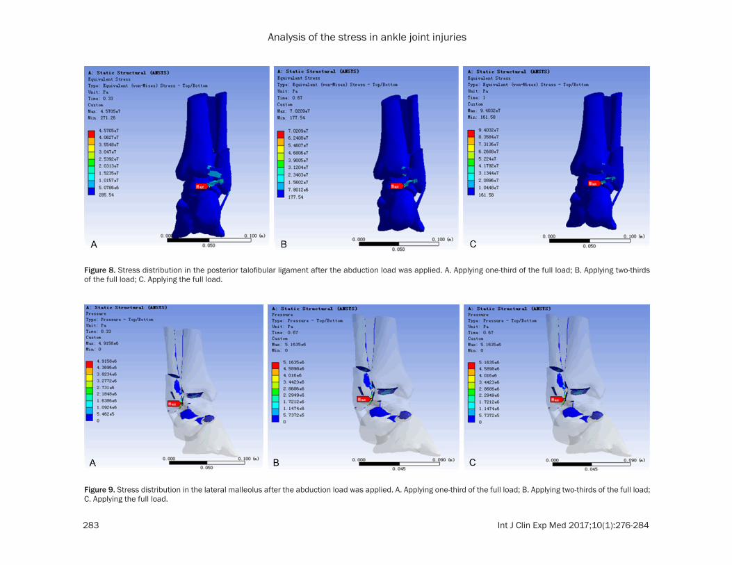
Analysis of the stress in ankle joint injuries
283 Int J Clin Exp Med 201710(1)276-284
Figure 8 Stress distribution in the posterior talofibular ligament after the abduction load was applied A Applying one-third of the full load B Applying two-thirds of the full load C Applying the full load
Figure 9 Stress distribution in the lateral malleolus after the abduction load was applied A Applying one-third of the full load B Applying two-thirds of the full load C Applying the full load
Analysis of the stress in ankle joint injuries
284 Int J Clin Exp Med 201710(1)276-284
late other injury mechanisms of the ankle joint and to review validate and investigate the occurrence of ankle diseases However taking the complexity of the ankle joint injury into con-sideration the construction of FE models for Lauge-Hanse pronation-abduction ankle joint injury still requires further investigation
Acknowledgements
The anatomical and biomechanical basis of the manual reduction mechanism of trimalleo-lar fractures based on the theory of tendon bundle bone (a project supported by the Na- tional Natural Science Foundation of China Grant No 81273785)
Disclosure of conflict of interest
None
Address correspondence to Dr Yongzhong Cheng Traumatic Orthopedics Wangjing Hospital of The China Academy of Chinese Medical Science Beijing China Tel 86 13810220180 Fax 861084739167 E-mail bless518139com
References
[1] Lauge-Hansen N Fracture of the ankle II Combined experimental surgical and experi-mental-roentgenologic investigations Arch Surg 1950 60 957-985
[2] Golanoacute P Vega J de Leeuw PA Malagelada F Manzanares MC Goumltzens V van Dijk CN Anatomy of the ankle ligaments a pictorial es-say Knee Surg Sports Traumatol Arthrosc 2010 18 557-569
[3] Siegler S Block J Schneck CD The mechani-cal characteristics of the collateral ligaments of the human ankle joint Foot Ankle 1988 8 234-242
[4] Chu TM Reddy NP Padovan J Three-dimensional finite element stress analysis of the polypropylene ankle-foot orthosis static-analysis Medical Eng Phys 1995 17 372-379
[5] Imhauser CW Siegler S Udupa JK Toy JR Subject-specific models of the hindfoot reveal a relationship between morphology and pas-sive mechanical properties J Biomech 2008 41 1341-1349
[6] Funk JR Hall GW Crandall JR Pilkey WD Linear and quasi-linear viscoelastic character-ization of ankle ligaments J Biomech Eng 2000 122 15-22
[7] Siegler S Block J Schneck CD The mechani-cal characteristics of the collateral ligaments of the human ankle joint Foot Ankle 1988 8 234-242
[8] Sarrafian S Anatomy of the foot and ankle de-scriptive topographic functional 2nd edition Philadelphia Lippincott Williams amp Wilkins 1993 pp 159-217
[9] Anderson DD Goldsworthy JK Li W James Rudert M Tochigi Y Brown TD Physical valida-tion of a patient-specific contact finite element J Biomech 2007 40 1662-1669
[10] Anderson DD Goldsworthy JK Li W James Rudert M Tochigi Y Brown TD Physical valida-tion of a patient-specific contact finite element model of the ankle J Biomech 2007 40 1662-1669
[11] Huiskes R On the modeling of long bones in structural analyses J Biomech 1982 15 65
[12] Haraguchi N Armiger RS Myerson MS Campbell JT Chao EY Prediction of three-di-mensional contact stress and ligament ten-sion in the ankle during stance determined from computational modeling Foot Ankle Int 2009 30 177-185
[13] Attarian DE McCrackin HJ DeVito DP McEl- haney JH Garrett WE Jr Biomechanical char-acteristics of human ankle ligaments Foot Ankle 1985 6 54-58
[14] Beumer A van Hemert WL Swierstra BA Jasper LE Belkoff SM A biomechanical evalu-ation of the tibiofibular and tibiotalar ligaments of the ankle Foot Ankle Int 2003 24 426-429
[15] Cheung JT An KN Zhang M Consequences of partial and total plantar fascia release a finite element study Foot Ankle Int 2006 27 125-132
[16] Cheung JT Zhang M Parametric design of pressure relieving foot orthosis using statis-tics-based finite element method Med Eng Phys 2008 30 269-277
[17] Brilakis E Kaselouris E Effects of foot posture on fifth metatarsalenspfractureensphealing aenspfi-niteenspelementenspstudy J FootenspAnkleenspSurg 2012 51 720-8
[18] Chen WP Ju CW Tang FT Effects of total con-tact insoles on the plantar stress redistribu-tion a finite element analysis Clin Biomech 2003 6 17-24
[19] Liu Q Zhang K Zhuang Y Li Z Yu B Pei G Analysis of the stress and displacement distri-bution of inferior tibiofibular syndesmosis inju-ries repaired with screw fixation a finite ele-ment study PLoS One 2013 3 8
[20] Shin J Untaroiu CD Biomechanical and injury response of human foot and ankle under com-plex loading J Biomech Eng 2013 135 101008
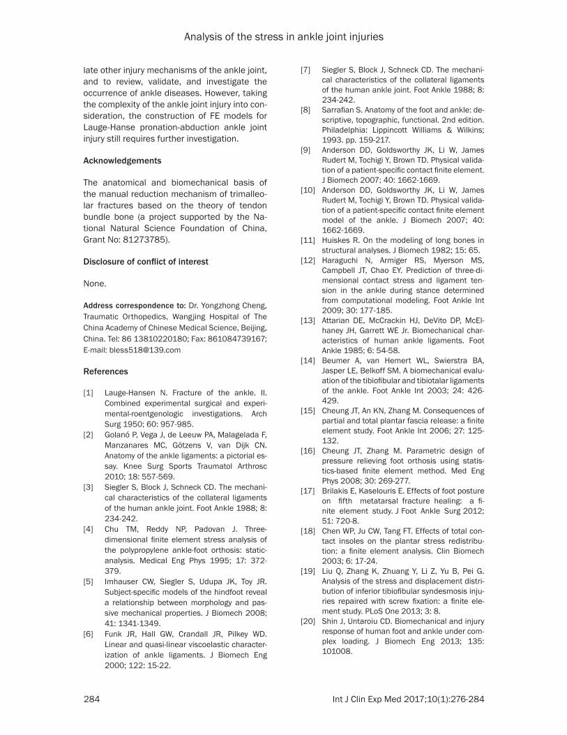
Analysis of the stress in ankle joint injuries
284 Int J Clin Exp Med 201710(1)276-284
late other injury mechanisms of the ankle joint and to review validate and investigate the occurrence of ankle diseases However taking the complexity of the ankle joint injury into con-sideration the construction of FE models for Lauge-Hanse pronation-abduction ankle joint injury still requires further investigation
Acknowledgements
The anatomical and biomechanical basis of the manual reduction mechanism of trimalleo-lar fractures based on the theory of tendon bundle bone (a project supported by the Na- tional Natural Science Foundation of China Grant No 81273785)
Disclosure of conflict of interest
None
Address correspondence to Dr Yongzhong Cheng Traumatic Orthopedics Wangjing Hospital of The China Academy of Chinese Medical Science Beijing China Tel 86 13810220180 Fax 861084739167 E-mail bless518139com
References
[1] Lauge-Hansen N Fracture of the ankle II Combined experimental surgical and experi-mental-roentgenologic investigations Arch Surg 1950 60 957-985
[2] Golanoacute P Vega J de Leeuw PA Malagelada F Manzanares MC Goumltzens V van Dijk CN Anatomy of the ankle ligaments a pictorial es-say Knee Surg Sports Traumatol Arthrosc 2010 18 557-569
[3] Siegler S Block J Schneck CD The mechani-cal characteristics of the collateral ligaments of the human ankle joint Foot Ankle 1988 8 234-242
[4] Chu TM Reddy NP Padovan J Three-dimensional finite element stress analysis of the polypropylene ankle-foot orthosis static-analysis Medical Eng Phys 1995 17 372-379
[5] Imhauser CW Siegler S Udupa JK Toy JR Subject-specific models of the hindfoot reveal a relationship between morphology and pas-sive mechanical properties J Biomech 2008 41 1341-1349
[6] Funk JR Hall GW Crandall JR Pilkey WD Linear and quasi-linear viscoelastic character-ization of ankle ligaments J Biomech Eng 2000 122 15-22
[7] Siegler S Block J Schneck CD The mechani-cal characteristics of the collateral ligaments of the human ankle joint Foot Ankle 1988 8 234-242
[8] Sarrafian S Anatomy of the foot and ankle de-scriptive topographic functional 2nd edition Philadelphia Lippincott Williams amp Wilkins 1993 pp 159-217
[9] Anderson DD Goldsworthy JK Li W James Rudert M Tochigi Y Brown TD Physical valida-tion of a patient-specific contact finite element J Biomech 2007 40 1662-1669
[10] Anderson DD Goldsworthy JK Li W James Rudert M Tochigi Y Brown TD Physical valida-tion of a patient-specific contact finite element model of the ankle J Biomech 2007 40 1662-1669
[11] Huiskes R On the modeling of long bones in structural analyses J Biomech 1982 15 65
[12] Haraguchi N Armiger RS Myerson MS Campbell JT Chao EY Prediction of three-di-mensional contact stress and ligament ten-sion in the ankle during stance determined from computational modeling Foot Ankle Int 2009 30 177-185
[13] Attarian DE McCrackin HJ DeVito DP McEl- haney JH Garrett WE Jr Biomechanical char-acteristics of human ankle ligaments Foot Ankle 1985 6 54-58
[14] Beumer A van Hemert WL Swierstra BA Jasper LE Belkoff SM A biomechanical evalu-ation of the tibiofibular and tibiotalar ligaments of the ankle Foot Ankle Int 2003 24 426-429
[15] Cheung JT An KN Zhang M Consequences of partial and total plantar fascia release a finite element study Foot Ankle Int 2006 27 125-132
[16] Cheung JT Zhang M Parametric design of pressure relieving foot orthosis using statis-tics-based finite element method Med Eng Phys 2008 30 269-277
[17] Brilakis E Kaselouris E Effects of foot posture on fifth metatarsalenspfractureensphealing aenspfi-niteenspelementenspstudy J FootenspAnkleenspSurg 2012 51 720-8
[18] Chen WP Ju CW Tang FT Effects of total con-tact insoles on the plantar stress redistribu-tion a finite element analysis Clin Biomech 2003 6 17-24
[19] Liu Q Zhang K Zhuang Y Li Z Yu B Pei G Analysis of the stress and displacement distri-bution of inferior tibiofibular syndesmosis inju-ries repaired with screw fixation a finite ele-ment study PLoS One 2013 3 8
[20] Shin J Untaroiu CD Biomechanical and injury response of human foot and ankle under com-plex loading J Biomech Eng 2013 135 101008