orel-tm-79 copy ini'o
TRANSCRIPT


OREL-TM-79
Copy Ini'o .
Contract Wo. W-7^05-eng-26
Reactor Division
WATER TEST DEVELOPMENT OF THE FUEL PUMP FOR THE MSRE
P. G. Smith
DATE ISSUED
MAR 2 71962
OAK RIDGE NATIONAL LABORATORY
Oak Ridge, Tennesseeoperated by
UNION CARBIDE CORPORATION
for the
U. S. ATOMIC ENERGY COMMISSION
OAK RIDGE NATIONAL LABORATORY LIBRARIES
3 44Sh DS467SE 5


Ill
CONTENTS
List of Figures
Abstract
Introduction
Experimental Apparatus
Pump . .- .
Test Loop
Carbon Dioxide Stripping Devices ......
Instrumentation. ...
Description of Tests
Head-Flow-Power-Speed Performance ......
Carbon Dioxide Stripping Tests .........
Pump Tank Liquid and Gas Behavior
Fountain Flow
Stripper Flow .....
. Gas Bubble Behavior in the Pump Tank Volume
Priming
Coastdown Characteristics
Test Results
Head-Flow-Power-Speed Performance
Carbon Dioxide Stripping Effectiveness . . .
Pump Tank Liquid and Gas Behavior ,
Fountain Flow . ,
Stripper Flow ,
Gas Bubble Behavior in the Pump Tank Volume
Priming . . . .
Coastdown Characteristics
Conclusions
Acknowledgments
References
e No
v
vii
1
2
2
2
6
9
12
12
12
ik
Ik
Ik
Ik
Ik
15
15
15
19
22
22
27
27
29
31
31
32
32
Pag'

IV
Page No.
Appendix • • 3^
Nomenclature . . 35
Table I ........ 36
Table II . . . 37
Table III ... 38
Computations for:
Table I.. kO
Table II . . kl
Table III . . . k2

V
LIST OF FIGURES
Fig. No. Captions Page No
1. Cross Section of Pump 3
2. Discharge Connection to Loop ..... k
3. Photo of Test Loop 5
k. Stripper Configuration 1 7
5- Stripper.Configuration 2 8
6. Stripper Configuration 5 10
7 • Venturi Calibration 11
8. Motor Calibration . 13
9. Hydraulic Performance, 13-in. Impeller . . .16
10. Hydraulic Performance, 11-in. Impeller ...;... 17
11. Prerotatioh Baffle 18
12. Head, Input Power, and Speed Versus Flow, 11-in.Impeller 20
13« Hydraulic Performance, 11-in. Impeller, EfficiencyContours Superimposed ................. 21
1^. Relative Effectiveness Versus Sweep Gas Flow .... 23
15- Half-Life Versus Stripping Flow 2k
16. Relative Effectiveness Versus Jet Velocity 25
17• Cross Section of Upper Labyrinth 26
18. Fountain Flow Versus Speed, 11-in. Impeller 28
19. Pump Inlet X-Section . 30


VI1
ABSTRACT
A vertical centrifugal sump-type pump.utilizing commercially
available impeller and volute designs was selected to circulate the
fuel salt in the Molten Salt Reactor Experiment (MSRE) . Tests were
conducted in water to determine the adequacy of the pump design, to
assist design of the prototype fuel pump, and to investigate the
effectiveness of xenon removal with high velocity liquid jets con
tacting sweep gas in the pump tank. Hydraulic head characteristics
were within +1 to -3 ft of manufacturers data for a given constant
speed. Adequate and necessary provisions were devised to control
the liquid and gas bubble behavior in the pump tank. The results of
priming and coastdown tests are reported. During the gas removal
tests, the fuel, xenon, and helium in the MSRE were simulated with
distilled water, carbon dioxide, and air, respectively. The best
configuration removed carbon dioxide from water at approximately 99/0
of the ideal removal rate when the stripping flow was 65 gpm and the
sweep gas flow rate was k scfm.

WATER TEST DEVELOPMENT OF THE FUEL PUMP FOR THE MSRE
P. G. Smith
INTRODUCTION
The Molten Salt Reactor Experiment (MSRE) is to be a low-pressure,
high-temperature, graphite moderated circulating fuel nuclear reactor
using fissile and fertile materials dissolved in molten fluoride salts
and is designed for a heat generation rate of 10 Mw (l, 2, and 3) . Its
goals include proving the safe and reliable operation of this nuclear
reactor concept and demonstrating the maintainability of molten salt
machinery. The investigation reported herein is concerned with the pump
required to circulate the fuel salt in the MSRE.
A centrifugal sump-type pump consisting :of a rotary element and
pump tank was selected for this application. The rotary element in
cludes the vertical shaft and underhung impeller, the shaft bearings,
and the means for lubricating and cooling the bearings . The pump tank
includes the volute (casing), suction and discharge nozzles, other
nozzles for accommodating inert gas purge, fuel sampling and enrichment,
liquid level sensing devices, a flange for mounting the rotary element,
and various liquid bypass flows for degassing and removing xenon poison
from the circulating fuel salt. The device used for removal of xenon
will be referred to as a "stripper" . Much of the design of the fuel
pump was derived from the past experience with similar pumps for
elevated temperature service which were developed during the Aircraft
Nuclear Propulsion Program at Oak Ridge-National Laboratory (k, 5,
and 6).
The initial phase of development and testing of the fuel pump was
conducted with water to ascertain the capability of the pump to meet the
hydraulic requirements of the fuel circuit and.to remove from the circu
lating fuel the xenon which will be generated by the fissioning process.
Data were taken on the head-flow-power-speed performance of the pump for
two impeller outside diameters, 13 and 11 inches. Various baffles were
devised to control splash, spray, and gas bubbles caused by the operation

of the bypass flows in the pump tank. The ability of the pump to prime
was determined at various liquid.levels of interest. The coastdown
characteristics of the pump were measured from various speeds and flows.
Attempts were made to measure indirectly the effectiveness with which
xenon poison might be removed from the circulating fuel using high
velocity liquid jets in contact with gas in the pump tank. During this
particular test the fuel and xenon were simulated, respectively, with
distilled water and carbon dioxide; this gas is much more soluble in
water than xenon is in molten salts of interest and. in addition provides
for convenient measurement of solubility.
Pertinent information from these water tests were incorporated in
the design of the prototype fuel pump and will be subjected to elevated
temperature testing at MSRE design conditions.
• EXPERIMENTAL APPARATUS
The experimental apparatus includes the pump, the test loop, and
the stripper configurations. A description of each follows:
Pump
The pump is shown in Fig. 1 and includes a centrifugal impeller and
volute with the impeller supported at the lower end of a vertical shaft,
grease-lubricated bearings for supporting the shaft, bearing housing,
pump tank bowl, and volute support. The pump tank bowl was fabricated
of plexiglas to permit visual observation of the behavior of the liquid
and the gas bubbles . Labyrinth-type seals were utilized on the impeller
inlet shroud and on the impeller support shroud. The impeller support
shroud labyrinth seal was supported on the impeller cover plate, which
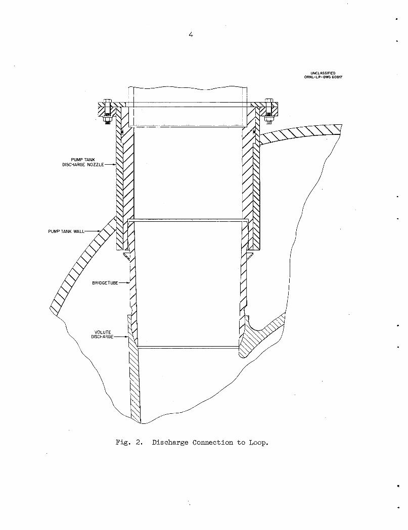
was sealed-to the volute by an elastomeric O-ring. The volute discharge
was connected to the pump tank discharge nozzle through a flexibly
mounted bridge tube. The connection arrangement is shown in Fig. 2.
Test Eoop
The test loop is shown in Fig. 3, which consists of the pump, piping,
venturi flowmeter, throttle valve (globe type), stripper flow circuits

LOWER LABYRINTH
UNCLASSIFIED
ORNL-LR-DWG 60816
STRIPPER
3 CONFIGURATION 5
LIQUID LEVEL
Fig. 1. Cross Section of Pump.
PUMP TANK
DISCHARGE NOZZLE
PUMP TANK WALL-
4
Fig. 2. Discharge Connection to Loop.
UNCLASSIFIEDORNL-LR-DWG 60817


(not shown), and a.cooler. The pump was driven with a 60 hp d.c.
variable speed motor. The vertical inlet pipe to the pump was fabri
cated of plexiglas to permit visual observation of the inlet flow con
ditions . A bundle of 1-in. diameter thin-wall tubes, 6-in. long,.was
added to the lower end of this pipe to reduce rotation of the water
column. The. cooler was installed in parallel with the main loop throttle
valve. A part of the main loop. flow.was bypassed through the cooler to
control the system temperature. The bypass flow was controlled by a
throttle valve located.in the bypass flow.circuit. Stripper configu
ration flow was supplied through a-tap located.just downstream of the
pump tank discharge nozzle. The stripper flow as well as the flow from
the impeller upper labyrinth passed through the pump tank and re-entered
the system at the impeller inlet. Throttle valves were used.to control
the stripper flow. Following the initial tests an orifice was added to
the nearly vertical section of the. loop between the discharge and the
venturi flow meter to decrease the pressure drop through the main throttle
valve.
Carbon Dioxide Stripping Devices
Tests were conducted wherein a portion of the pump discharge flow
was introduced into the gas volume of the pump tank through high velocity
jets (strippers). A number of configurations were investigated, starting
with a single stream and progressing to configurations which gave in
creasingly more fresh liquid-gas interface.
The strippers tested and identified in Table I (Appendix) are
described as follows (in each test two strippers were used):
1. Configuration 1 is shown in Fig. k. The flow discharged from
one side of the can through l/^-in. .holes. For this test the holes were
submerged below the liquid surface in the pump.tank.
2. Configuration 2 is shown in Fig. 5• The lower end of the entry
tube was closed and the beaker was packed with Inconel wool. The strip
ping/flow entered the pump tank gas space in tangential direction as a
spray. One beaker contained 8^ spray holes, l/8-in. in diameter, and
the other contained 30 spray holes, l/U-in. in diameter.

UNCLASSIFIED
ORNL-LR-DWG 60818
PUMP TANK ^LIQUID LEVEL--.
s s
li
• ^=r^ tT-^E^ZTt~
~~T"
r^r^". ^
SIXTY %-in. HOLES ^—»~^*/
li
3/4-in.IPS-»' | 5 n. e1/2in.
? 1GRAVITY
' ' '
-^ 5 in *-
Fig. 4. Stripper Configuration 1.

T-GRAVITY
r
PACKED WITH INCONEL WOOL-
£
K
1
UNCLASSIFIED
ORNL-LR-DWG 60819
-PUMP TANK
LIQUID LEVEL
__kDRAIN HOLES
Fig. 5. Stripper Configuration 2.

3• Configuration 3 was the same as No ..2, except for the size of
spray holes, and the number of holes. Each stripper contained 162
spray holes, l/l6-in. in diameter, with the beaker suspended such that
the spray.was circumferential.
k. Configuration k was the same as No. 3> except the number of
holes was reduced by a factor of two and the spray,was directed radially
inwards toward the pump shaft.
5 • Configuration 5 was a toroid constructed of pipe as shown in
Fig. 6, and located in the pump tank as shown in Fig. 1. Each stripper
contained two rows of 80 holes each, l/l6-in. in diameter.
INSTRUMENTATION
Instrumentation was provided to measure venturi pressure drop,
discharge pressure, pump shaft speed, water temperature, motor input
power, fountain flow, stripper flow, pH value of the water, and pump
tank liquid level.
Three different methods were used in measuring the venturi pressure
drop: mercury manometer, difference between individual pressures measured
at the inlet and throat, and by differential pressure transmitter. Cali
bration of the venturi was provided by. the vendor, and it is shown in
Fig. 7- Individual pressures at the inlet and throat were indicated on
Bourdon tube gages, 0-30 psi range, l/8 psi subdivision, and l/k<?o ac
curacy. The differential pressure transmitter was read out on a dif
ferential gage, 0-50 psi range, l/2 psi subdivision, l/k^o accuracy. The
flow is estimated to be accurate within ± jfo-
The discharge pressure was measured on a Bourdon tube gage, 0-100 psi
range, l/2 psi subdivision, and l/k'fo accuracy.
The pump shaft speed was measured.by use of a 60-tooth gear mounted
on the shaft, a magnetic pickup, and a .counter which indicated directly
in rpm.
The water temperature was measured with a dial-type thermometer,
0 to 2^0 F range, 2 F subdivision.
Motor input power data was obtained by two methods: power recorder,
0 to kO kw range, 0.8 kw subdivision and power analyzer which indicated


120
i 100
a.<
60
20
11
UNCLASSIFIEDORNL-LR-DWG 60820
1
r
y
//
•
y
-•'
.l--0*^*m"^
200 400 600 800 1000 1200 1400 1600 1800 2000 2200
0, FLOW (gal/min)
Fig. 7. Venturi Calibration.

12
current and.voltage. The power measurements were in error during most
of the testing with the 13-in-o.d. impeller which preceded tests with
the 11-in. impeller. During this period, investigations were conducted
to.locate and correct the source of error. Satisfactory power measure
ments were obtained with the 11-in. impeller. The motor calibration
curve is shown in Fig. 8.
The fountain flow was measured by directing the flow through 90°
V-notch weirs and measuring the height of the flow column.
The stripper flow was measured by use of rotameters.
The pH value of.the water was indicated with a Beckman pH meter,
Model H^2, range 0 to.Ik pH.with an accuracy of.0.03 pH.
The pump.tank liquid level was indicated with a scale marked off in
0.1-in. divisions. Zero level corresponded with the center line of the
volute.
DESCRIPTION OF TESTS
Head-Flow-Power-Speed Performance
Hydraulic performance data were obtained over a wide range of
operating conditions with impellers of 11- and. 13-in. outside diameter.
Two methods of operation were used: speed was varied (700 to 1300rpm)
at constant system resistance for several values of resistance with the
13-in. impeller, and system resistance was varied at constant speed for
several values of speed (700 to 1300 rpm) with the 11-in. impeller. Data
were obtained for computing head, flow, brake horsepower, and efficiency.
Carbon Dioxide Stripping Tests
A number of tests were performed with both impeller diameters to
ascertain the change in effectiveness of CO removal caused by various
stripper configurations, flow rates, jet velocities, and sweep gas flow
rates. Carbon dioxide in dry-ice form was added to the circulating dis
tilled water in the system until saturation was achieved, after which
time the stripper flow was started. Readings of pH of the water were
taken versus time to determine the time required to reduce the CO con
centration by a factor of two. A total of 37 tests were performed.

13
UNCLASSIFIED
ORNL-LR-DWG 6082160 1 1 1 1 1 , —r— .
850 rpm »^50
2400 rpm -j*n
4060-hpdc G.E. MOTOR
SERIAL NO. 7287063 "
i
1-30
0.
20
10
0
10 20 30 40
OUTPUT (hp)
50
Fig. 8. Motor Calibration.
60 70

Ik
An expression was derived to give the theoretical time required to
reduce the C0p concentration by one half. Comparison of the theoretical
and experimental data is reported as relative effectiveness of the
stripper.
Pump Tank Liquid and Gas Behavior
Fountain Flow
Considerable testing was performed to,observe the flow of water from
the impeller upper labyrinth (flow up.the shaft and return to the system
through the pump tank volume) and to develope adequate control of the re
turn of this flow.into the pump tank liquid, keeping the splatter of water
and gas bubble formation to a minimum (see Fig. l).
Clearances were varied between the shaft and the impeller upper
labyrinth and the impeller upper shroud and seal plate. The corres
ponding fountain flows were measured.
Stripper Flow
The flow through the various stripper configurations was measured
and baffling was developed to control splatter and gas bubble formation.
Gas Bubble Behavior in the Pump Tank Volume
Throughout all of the testing the formation and behavior of gas
bubbles were observed, in the pump tank volume. Baffling was devised.to
prevent entry of gas bubbles into the pump inlet.from the pump tank
volume.
Priming
The priming characteristics of the pump'were checked at various
static,liquid levels-in the pump tank. The ability of the pump to hold
prime as the liquid, level in the pump tank was being lowered was in
vestigated. Data were obtained of head-flow-speed performance and of

15
change in starting level for various starting levels as the pump was
accelerated from zero to design speed.
Coastdown Characteristics
A number of coastdown tests were made from various pump operating
conditions. The power supply to the pump drive motor was interrupted
while the pump.was operating at specific .speed and flow conditions, and
the time required to reach reduced system flow and pump speed was de
termined .
TEST RESULTS
Head-Flow-Power-Speed Performance
Hydraulic performance data were obtained over a wide range of head
and flow conditions at several speeds for the 8.in. x 6 in. volute, using
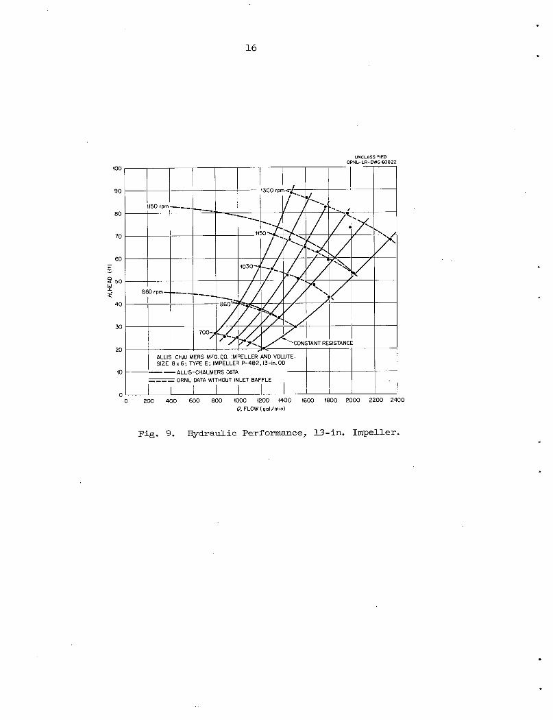
impellers of 13- and 11-in. outside diameter. These tests with the 13-in.
diameter impeller were conducted without a baffle in the pump.inlet. The
13-in. impeller performance is presented in Fig. 9, which is a plot of
head versus flow at.various speeds. The flow is total flow consisting1
of system flow, fountain flow, and stripper flow. The corresponding
data are tabulated in Table II (Appendix). Aliis-ChaLners data are also
shown for comparison. The heads obtained are increasingly lower than
Allis-Chalmers data with decreasing flow at constant speed.
The performance obtained with the 11-in. diameter impeller is pre
sented in Fig. 10, which is a plot of head versus flow at various speeds.
The flow is total flow consisting of system flow, fountain flow, and
stripper flow. The corresponding data are.tabulated in Table III (Ap
pendix) . Data for three different inlet configurations are shown: in
two configurations a prerotation baffle was located at the inlet to the
impeller; and the other configuration had none. The baffle consisted of
two plates arranged, in a cross as shown in Fig. 11; it had the effect of
increasing the head at the lower range of flows on a constant speed line .
There was essentially no difference in the results obtained with the two
16
UNCLASSIFIED
ORNL-LR-DWG 60822
0 200 400 600 800 1000 1200 1400 1600 1800 2000 2200 2400
<?, FLOW (gal/min)
Fig. 9. Hydraulic Performance, 13-in. Impeller.

88
80
72
64
56
£ 48o<UJI
. 40
a?
32
24
16
17
UNCLASSIFIED
ORNL-LR-DWG 60823
ALLIS CHALMERS MFG. CO. IMPELLER-VOLUTE
SIZE 8x6; TYPE E; IMPELLER P-482, 11-in. OD
. ALLIS CHALMERS DATA
ORNL DATA
o WITHOUT INLET BAFFLE 4-19-61
• WITH INLET BAFFLE (4-in. LONG) 4-20-61 _A WITH INLET BAFFLE (21/2-in. LONG) 6-19-61
0 ' 200 400 600 800 1000 1200 1400 1600 1800 20000, FLOW (gal /min)
Fig. 10. Hydraulic Performance, 11-in. Impeller.

18
UNCLASSIFIED
ORNL-LR-DWG 60824
FLOW
Fig. 11. Prerotation Baffle.

19
sizes of baffles. Curves of head and pump.input power versus flow at
various speeds are shown in Fig. 12. The input power change versus
flow for constant speed operation is slight.
The prerotation baffle was not fully tested with the 13-in. im
peller. Were such a baffle used with the 13-in. impeller, performance
would be more nearly coincident with the published Aliis-Chalmers data.
From the power data obtained with the 11-in. diameter impeller,
efficiency contours were computed which are shown in Fig. 13, super
imposed on a plot of head-flow-speed data.
Carbon Dioxide Stripping Effectiveness
In the stripping tests, data were obtained to determine the time
required to reduce the CO concentration by one half (half-life) . The
change in pH value of the distilled water was measured over a range from
k to 6 versus time . For plotting purposes the pH values were converted
to the logarithm of the molarity of CO to determine the half-life.
Theoretical half-life (t = 0.69 v/Q ) was computed for each tests
and compared with the experimental half-life to give relative effective
ness .
The results of.the carbon dioxide stripping tests are presented in
Table I (Appendix) . Related in the table are data pertaining to the
stripper configurations, by-pass flows, liquid level in the pump tank,
sweep gas flow rate, system volume, jet velocity, experimental half-life,
ideal half-life, and relative effectiveness.
The first six tests were preliminary; the flow was simply bypassed
through the pump tank without passing through strippers. These tests
were performed to provide a base from which to proceed, with strippers.
Values of relative effectiveness ranged from 10 to kO percent.
Tests 7 through .16 were concerned mainly with varying the stripper
configuration. Other variables may be noted in the data shown in the
table. Values of effectiveness ranged from 15 to 68 percent.
From the results of tests through No. 16, configuration 5 (Fig. 6)
was derived and used for the remainder of the tests, 17 through 39•

~ 30
S 20
10
0
72
64
56
48
r 40
32
24
16
20
UNCLASSIFIEDORNL-LR-DWG 60825
- •- ». m1300 rpm • « < •"
1150•_ •— _• .»-•—
860• .»—•— .• -• —•—
d
N̂^**
s%
^v. fie0
48.5. ft, 1150 rpm; 17.5 gal
11-in. IMPELLER, 8 »6 IMPE
'min FOUNTAIN F
LLER-VOLUTE
"LOW
2V2 -in. PRE ROTAIIC N BAFF LE
0 200 400 600 800 1000 1200 1400 1600 1800 2000
0, FLOW (gal/min)
Fig. 12. Head, Input Power, and Speed Versus Flow, 11-in. Impeller.

- 40
C 32
21
UNCLASSIFIED
ORNL-LR-DWG 60826
0 200 400 600 800 1000 1200 1400 1600 1800 2000
<?, FLOW (gal/min)
Fig. 13. Hydraulic Performance, 11-in. Impeller, EfficiencyContours Superimposed.

2g
In tests 17 through 2k, the flow and jet velocity were varied simul
taneously, at a constant sweep gas flow rate. The relative effectiveness
varied, from 27 to 99 percent.
In tests 10, 13, Ik, .17,:18, and 25 through 29, sweep gas flow rate
was varied with the other variables held constant, and two stripper con
figurations were used. The relative effectiveness varied from ^7 to
72 percent. These data are plotted in Fig. Ik, Relative Effectiveness
Versus Sweep Gas Flow, for two configurations.
In tests 30, 32,,33, 35, and 39, the stripping flow was varied with
the other variables held constant. The relative effectiveness varied
from 70 to 90 percent. The results from these tests are shown in Fig. 15,
Half-Life (defined on page 18) Versus Stripping Flow. Experimental and
theoretical curves are shown.
In tests.30, 31, 3k, and 36, the jet velocity was varied with the
other variables held constant. The relative effectiveness varied from
27 to 90 percent. The results are shown in Fig. 16, Relative Effective
ness Versus Jet Velocity.
Configuration 5 was selected, for the MSRE fuel pump, and was in
corporated in the. design of the prototype fuel pump. Tests 37 and 38
yielded effectiveness values of 52 and 55 percent, respectively. These
tests were performed at the following conditions, .reasonably attainable
in the MSRE: stripping flow rate of 65 gpm,,and sweep gas flow rates of
0.05 and 0.07 scfm, respectively.
Pump Tank Liquid and Gas Behavior
Fountain Flow
Observations of the fountain flow from the impeller upper labyrinth
(Fig. 17) revealed the need to control it;, the slinger impeller was
causing an undesirable spray. This spray was contained and controlled
by use of a cover enclosing the, labyrinth and slinger impeller, and
having drain ports located at its lower end.
Approximate measurements of the fountain flow were made using weirs
located in the windows -carrying the flow from the fountain into the pump

100
> 60
vu 20
23
JET VELOCITY CONSTANT
STRIPPING FLOW CONSTANT
q, SWEEP GAS FLOW (fr/min)
UNCLASSIFIEDORNL-LR-DWG 60827
Fig. 14. Relative Effectiveness Versus Sweep Gas Flow.

1.6
~ 1.2c
E
l±J
V 0.8
<I
0.4
24
—I T"
TEST NUMBER
EXPERIMENTAL
JET VELOCITY CONSTANT
SWEEP GAS FLOW RATE CONSTANT
STRIPPING CONFIGURATION CONSTANT
10 20 30 40 50
STRIPPING FLOW (gal/min)
UNCLASSIFIEDORNL-LR-DWG 60828
60 70 80
Fig. 15. Half-Life Versus Stripping Flow.

100
£ 80
ijj
>
>
60
40
w 20
25
,7«18
36
STRIPPING CONFIGURATION CONSTANT
SWEEP GAS FLOW RATE CONSTANT
STRIPPING FLOW CONSTANT
10 15 20 25
v, JET VELOCITY (ft/sec)
UNCLASSIFIEDORNL-LR-DWG 60829
30 35 40
Fig. 16. Relative Effectiveness Versus Jet Velocity.

TOP EDGE
OF IMPELLER
26
SLINGER IMPELLER
CLEARANCE C
UNCLASSIFIED
ORNL-LR-DWG 60830
SHAFT-
Fig. 17. Cross Section of Upper Labyrinth.

27
tank. Values of fountain flow for several labyrinth clearances are as
follows:
13-in. Diameter Impeller, Ih-50 gpm, 1030 rpm, 50 ft Head
Configuration
Number Clearance "A" Clearance "B",
1 0.015 0.015
2 0.015 0.0k)
3 0.015 0.0U0
k 0.015 0.060
Configuration k was used with the 11-in. diameter impeller and the
fountain flow was measured at various speeds along a .constant resistance
line defined by 1300 gpm and h-5 ft. The fountain flow versus speed is
shown in Fig. 18. Configuration k was adopted for use on the prototype
MSRE fuel pump.
The direction of the fountain flow was observed over the range of
conditions from which head-flow-speed data were obtained with both the
11-in. and 13^in. impellers. The flow of liquid was found always to be
outward from the shaft annulus into the pump tank, which is the desired
direction.
Stripper Flow
Considerable splatter of liquid resulted from impingement of this
flow onto the volute and volute support. Control of this splatter was
obtained through use of baffles installed on the stripper and on the
volute support.
Gas Bubble Behavior in the Pump Tank Volume
Entrance of the fountain and stripper flows into the pump tank liquid
caused gas bubble formation in the liquid. Control was obtained through
use of a baffle installed on the volute which deflects bubbles radially
Clearance "C", Flow, gpm
0.090 7.5 - 10
0.090 10 - 12
0.250 10 - 12
0.250 , 15 - 17.5
*
Each configuration was basically the same. Only the clearances
were different

5o
£
O
20
18
16
14
12
10
28
UNCLASSIFIED
ORNL-LR-DWG 60831
11-i
130
n.-dia IMPELL
O-gal/min LO
ft HEAD
.ER
DP FLOW
'*m
45-
'
*•
S
800 900 1000 1100
SHAFT SHAFT (rpm)
1200 1300
Fig. 18. Fountain Flow Versus Speed, 11-in. Impeller.

§9
outwards in the tank and by forcing these two flows to enter the
impeller inlet at the lowest elevation in the tank as shown in Fig. 19,
which may be compared to Fig. 1.
Priming
Priming tests were conducted with the 13-in. impeller in which the
pump was accelerated from zero to 1030 rpm in approximately 30 seconds,
noting the change in pump tank liquid level and observing attainment of
normal pump head and flow performance. The following operating levels
were noted for the listed starting levels:
Static Liquid Level Operating Liquid Level
(in .) (in .)
13-in. impeller
+2 +1.2 .
+1.5 +0.6
+1 -0.9
+0.5 -2.1
11-in. impeller
+2 +1
+1 -1.5
0 would not prime
Normal hydraulic performance was achieved at the end of pump accele-4.0 7«
ration for all runs except the 0.5-in. starting level with the 13-in.
impeller and the zero level with the 11-in. impeller. The 13-in. impeller
required an additional minute for priming at the 0.5-in. level and the
11-in. impeller would not prime at the zero level. These data should not
be used for reactor system computations unless differences in volumes of
system trapped gas are accounted for.
Reference level is center line of the volute. + is above center
line .

30
Fig. 19. Pump Inlet X-Section.
UNCLASSIFIED
ORNL-LR-DWG 60832

31
Other priming tests were performed jby lowering of the liquid level
in the pump tank slowly with the pump running. A test was performed tilth
the 13-in. diameter impeller operating at 1+50 gpm, 50 ft head, and
starting liquid level at .1 l/2-in. above center line of the volute. In-
gassing began at approximately k l/2-in. below the center line of the
volute. At 5 l/2 in. below the center line of the volute, the system
flow dropped to 700 gpm, and 6 l/2 In..below the center line of the
volute, the flow reduced to zero.
A test was performed with the 11-in. impeller operating at 1250 gpm,1 5^>.7»
.4-5 ft and starting liquid level at 1 1/2 in. above the center line of the
volute. Ingassing began at approximately 3 in. below the center line of
the volute. Vigorous ingassing and loss of head and flow began at 3 l/2 in.
below the volute center line.
Coastdown Characteristics
• Coastdown tests were performed on the.drive motor and pump with the
13-in. impeller to determine the,time required for the unit,to stop.after
opening the drive motor circuit from the electric supply. Tests were
performed on the same flow resistance line for operating speeds of 1150,
1030, and 860 rpm at flow rates of 1630,. 14-50, and 1210 gpm, respectively.
Coastdown times to zero speed ranged from 10.1 to 10.k sec, and for flow
reduction to 540 gpm, the times ranged from 1.5 to 2.0 sec.
CONCLUSIONS
From the experimental hydraulic characteristics, the total head was
found to deviate from, reported data by +1 to -3 ft. It was found necessary
to insert a prerotation baffle in the inlet to improve the head at reduced
flows.
Based on the water test results, a 11.5-in. diameter impeller will
be required to meet the reactor design head and flow (48.5 ft and 1200 gpm).
This dimension will be more precisely determined during the prototype fuel
pump tests.

32
Fountain flow was observed over the whole range of operation and
found ,to be outward from the upper labyrinth into the pump tank, which
is the desired direction. Gas bubbles created by the fountain and
stripping flows were removed in the pump tank with assistance from the
various baffles.
With regard to priming, the pump would prime (full head and flow)
instantaneously with speed at static levels of 1 in. or more above the
center line of, the volute.
Gas stripping was accomplished in the pump tank with a relative
effectiveness of up to 99 percent. Sweep gas flow rate, stripping flow,
and jet velocity were found to have quite pronounced effects on the
stripping rate of a given stripper configuration. It was concluded that
the zenon removal rate will be primarily dependent on the fraction of
fuel processed rather than on improved stripper configurations.
The hydraulic characteristics were found to be adequate for the
anticipated requirements of the fuel circuit of the MSRE. The required
control of liquid and gas behavior in the pump tank was accomplished by
the use of baffles.
ACKNOWLEDGMENTS
The following specific contributions are acknowledged which comprise
the main talents required to complete the investigations: L. V. Wilson,
design; F. F. Blankenship, devised stripping tests; R. F. Apple, chemical
aspects of stripping tests; and J. M. Coburn, test operation, data taking,
and computations .
REFERENCES
1. R. B. Briggs, MSRP Quar. Prog. Rep. for Period August 1, i960
to February 28, 1961, ORNL-^3122, June 20, 1961.
2. R. B. Briggs, MSRP Prog. Rep. for Period March 1 to August 31,
1961, OREL-3215, January 12, 1962.
3. S. E. Beall, W. L. Breazeale, B. W. Kinyon, Molten-Salt Reactor
Experiment Preliminary Hazards Report, ORNL-CF 61-2-46, February.28, 1961.
33
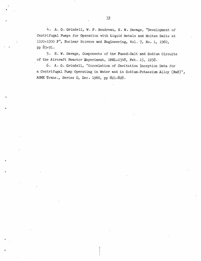
k. A. G. Grindell, W. F. Boudreau, H. W. Savage, "Development of
Centrifugal Pumps for Operation with Liquid Metals and Molten Salts at
1100-1500 F", Nuclear Science and Engineering, Vol. 7, No. 1, i960,
PP 83-91.
5' H. W. Savage, Components of the Fused-Salt and Sodium Circuits
of the Aircraft Reactor Experiment, ORNL-2348, Feb. 15, 1958.
6. A. G. Grindell, "Correlation of Cavitation Inception Data for
a Centrifugal Pump Operating in Water and in Sodium-Potassium Alloy (NaK)",
ASME Trans., Series D, Dec. i960, pp 82I-828.


Nomenclature
Table I
Table II
Table III
Computations
35
APPENDIX


37
NOMENCLATURE
t, Half-life, min.
V, System volume, gal.
Q , Stripping flow, gal/min.s
C, CO concentration, pH reading
q., Sweep gas flow rate, ft-ymin.
e, Relative effectiveness, dimensionless
Q, Total flow, gal/min.
H, Total head, ft.
v, Jet velocity, ft/sec .

38
Table I. C02 Stripping Tests of MSRE Primary Pump Circulating H20
Impeller Diameter:Impeller Diameter:
System Water Flow:
Head: 50 ft
Water Temperature:
13 in. for tests 1 through 2411 in. for tests 25 through 391450 gpm
65 F
la 2 3 4! 5 6 7 8 9 10 11 12 13 14 15
Stripper Configuration By-Pass Flow (gpm) Half-Life, t (min)
LiquidLevelb(in.)
Sweep Gas
(Air)Flow
(cfm)
Direction of
Stripper Flow
Jet
Velocity
(ft/sec).
System
Volume
(gal)
Total
By-PassFlow
(gpm)
Test
No.No.
Number
of
Holes
Diameter
of
Holes
(in.|)Stripper Fountain Experimental Theoretical
Relative
Effectiveness
1 35 8 4.0 0 Submerged 96 42 15.0 1.57 10.5
2 35 8 4.0 0 96 42 16.0 1.57 9.8
3 18 15 4.0 0 96 32 12.0 2.06 17.2
4 18 15 4.0 0.1 96 32 8.0 2.06 24.2
5 ( 35 15 4.0 0.1 96 50 10.0 1.34 13.4
6]
0 15 4.0 0.1 96 15 11.0 4.45 40.5
7 1 60 1/4 26 15 2.5 0.1 4.6 91 41 10.0 1.55 15.5
9 2 84\30 J
1/8\1/4;
35 15 1.5 0.1 C ircumferential 8.9) •'6.2/
88 50 3.0 1.22 40.6
10 3 324 i/ie 35 15 1.5 0.1 18.5 88 50 2.6 1.22 46.9
12 3 324 lie 35 15 3.8 0.1 18.5 96 50 3.2 1.32 41.7
13 3 324 1/16 35 15 1.5 8.6 18.5 88 50 1.8 1.22 67.7
14 3 324 1/16 35 15 1.5 4.3 18.5 88 50 2.2 1.22 55.4
15 '5 324 l/ite 0 ' 15 1.5 0.1 0 88 15 6.8 4.06 59.7
16 4 162 l/l6 35 15 1.5 0.1 Radially in
ward
37.0 88 50 2.0 1.22 61.0
17 5 320 ±/k 35 15 1.5 4.3 18.5 88 50 1.7 1.22 72.8
18 5 320 1/^6 35 15 1.5 4.3 18.5 88 50 1.7 1.22 71.8
19 5 200 i/i6 50 15 1.5 4.3 46.2 88 65 ' 1.0 0.94 98.9
20 5 200 1/^6 50 15 1.5 4.3 46.2 88 65 0.9 0.94 99.0
21 5 320 1/^6 70 15 1.5 4.3 40.5 88 85 0.9 0.72 80.8
22 5 320 1/16 70 15 1.5 4.3 40.5 88 85 0.9 0.72 82.7
23 5 215 1/16 44 15 1.5 4.3 37.8 88 59 1.1 1.03 96.8
24 5 215 1/16 44 15 1.5 4.3 37.8 88 59 1.0 1.03 98.0
25 5 320 1/16 35 15 1.5 0 18.5 ' 88 50 2.5 1.22 48.8
26 5 320 1/16 35 15 1.5 0 18.5 88 50 2.6 1.22 46.9
27 5 320 l/l|6 35 15 1.5 0.05 18.5 88 50 2.5 1.22 48.8
28 5 320 1/16 35 15 1.5 0.07 18.5 ' 88 50 2.4 1.22 50.8
29 5 320 1/16 35 15 1.5 1.0 18.5 88 50 2.3 1.22 53.0
30 5 160 1/16 35 15 1.5 4.3 37.0 88 50 1.4 1.22 89.6
31 5 200 1/3J6 35 15 1.5 4.3 29.6 88 50 1.5 1.22 83.6
32 5 200 1/16 44 15 1.5 4.3 ° 37.0 88 59 1.4 1.04 73.833 5 228 1/3J6 50 15 1.5 4.3 37.0 88 65 1.2 0.94 78.3
34 5 240 1/16 35 15 1.5 4.3 27.0 88 50 1.6 1.22 76.3
35 5 274 l/l'6 60 15 1.5 4.3 37.0 88 75 1.2 0.81 70.2
36 5 280 1/16 35 15 1.5 4.3 23.1 88 50 1.7 1.22 71.737d 5 290 1/16 50 15 1.5 0.05 28.8 88 65 1.8 0.94 52.2
38d 5 290 1/16 50 15 1.5 0.07 '28.8 88 65 1.7 0.94 55.3
39 5 300 i/i,6 62 15 1.5 4.3 34.8 88 77 1.1 0.79 72.2
See appendix for computations relative to indicated columns.
Level referred to centerline of volute.
"Data from R. G. Apple,
^System flow, 1200 gpm;Reactor Chemistry Division,
head, 48.5 ft.

ON
oC
M
-m
-
bo
a•H-pcdoPi
•HOIcdS•rHPiF
4PiOPiC
D•HH0IPi•HI
cn
HPiO<rl
a13oPi
OFh
nciC
D0
)ft
COIc?HPh
•dcdCD
KHCD
H••8EH
(AJ
OCM
ON
HtoL>
NO
HmHNT
Hen
CM
HHOHOn
to!>NO
mst
en
CM
cdH
-dcdCD
W.
Hcd•
-POEH
PI>
s•H
-p
J)(J
J)-P
60
OCU
=H
arH
K^
—cd
a;
FhPi
CU
ft
ft
•Hin
-PC
O.
rH^
->cd
>a
-PO
ft
OH
M
Pi•Hcd
>^
-po
aPi
rHft
3-P-4
--bo,O
—-
CM3oPi
•HO-P
•HPiOPi
•rl
O
bD>
cdO
OH
ft
bO
^
ft
bO
>Rft
bO
•rHCQft
CD
>
•H
ft
CO<
ft
cdbO
O-H
PiCO
.aft
-PbD
CD
iHH
COPi
ft
CU
-PbO
CU
<H
PiPi
cdpi
^3
WO
CO
CO
CD
bO•H
Pi•rl
QC
mC
Q
ft
Pi-p
CDpi
N
££
hcd
o-PPi
OC
D
PiC
U-P
T)
2U
ft
OPi
OH
CU
KPiO-PO2
IbOPi•H-dcdCD
K
-d
—v
cuB
CDft
ft
Pi
to
i>in
rHin
cn
tost
ol>
ioto
into
vo
cm
en
in
noto
to
l>
in
Hin
o\
st-h
\o
en
to
mvo
en
st
L>
l>
en
Hcn
cm
ento
on
en
cm
cnst
in!>
to
mno
cn
st
men
monl>
!>to
mCNJ
HrHto!>
OO
oon
cm
ento
CM
CMst
mnD
cmto
mCM
HONto
rH
CMto
in
HO
cn
Oo
ost
no
in
mt>
CMSt
CM
cm
cn
mnoto
mrH
on
en
ocmto
mcm
o
rH
on
on
cm
mON
OCM
St
ON
nO
OnO
Oto
cm
st
ml>to
HON
ON
CM
in
to
CM
C-
CM!>
CM
rH!>to
CM
nost
om
to
en
mrH
cm
on
cm
en
mvo
t>
CM
rH
L>to
CM
St
rH
ON
VO
ON
OrH
CM
CM
en
rH
CM
en
en
en
rHC
Mst
mm
i-lr
HC
MC
nst
OrH
rH
CM
CM
rH
CM
CM
cn
st
inen
to!>
int>
t>O
NC
MO
tOO
CMst
NO
rHH
HrH
ON
CM
m!>
OrH
r-\rH
CM
en
vo
ot>
mo
ml>
on
to
rHC
nN
O!>
ON
HH
rHrH
r-\
On
CM
mF
-o
HH
rHC
M
inrH
ON
rHO
CM
OO
nC
Mst
cmm
t>o
en
HrH
HC
MC
M
On
CM
m!>
orH
rHrH
CM
tot>
oto
mto
toen
l>n
oO
NrH
St-
mL
><
-\r-\
HH
ON
CM
mL
>o
rHH
HC
M
st
st
mt>
!>
ON
Oto
HN
Oi>
oh
mst
HH
HrH
ON
CM
mL
>o
rlH
iH
CM
cm
mst
to
on
mto
cm
on
in
ocm
mno
on
r-\
HH
rHH
on
cmm
l>o
t-HrH
rHC
M
Ostin
in
mO
NL
>m
min
i>
in
in
NO
Oo
ON
in
mm
vo
oN
in
in
mto
nin
ocM
en
st
i>!>
!>H
HH
rHrH
st
toO
OO
L>
to
OO
OrlH
rl
rHst
L>
!>
C-
HH
HH
rH
tost
OO
ON
Oto
OO
OrlrlH
mo
nst
no
orH
HC
MC
Men
mvO
On£>
no
st
m!>
i>to
CM
st-l>
!>
l>r-\
HH
r-\
H
on
mo
oo
NO
too
oo
HrH
rH
CM
m!>
O!>
rH<
-\rH
HH
CM
OO
OO
£>
ON
OO
O
NO
st
st
toCM
HC
MC
MC
Men
tOO
NO
OC
MS
tN
OL
>to
ON
Ost^
mm
ON
i>
in
mm
t>
min
NO
OO
ON
in
mm
\OO
Nin
inm
to
Hm
ocM
en
st
!>i>
i>H
rlH
HH
st
too
oo
i>to
oo
orH
rHrH
ocm
toin
ost
en
st
t>m
to
ocm
en
mr-i
HH
rH
HSt
L>
l>!>
r-^rH
HrH
rH
to
st
oo
oNO
to
oo
orH
rH
rH
om
om
oL
>rH
cmst
en
oen
no
t>o
nrH
HH
rH
H
mo
nst
no
orH
rHcm
cm
en
mn
oo
no
no
st
mL
>!>
to
mo
mo
oto
inen
inL
>H
St
!>
ON
CM
rHrH
rHrH
CM
CM
st
L>
!>-
t>rH
HH
rHrH
on
mo
oo
NO
too
oo
rHrH
rH
in
in
oin
om
st
toen
rHo
nH
en
mt>
HH
rlH
cmm
i>o
-i>
HH
rlrlH
CM
OO
OO
l>O
NO
OO
rHrH
rH
oo
mm
cmN
ON
OC
nN
OrH
L>
ON
HC
Mst
rHrH
<-{
NO
st
St
tOC
MH
CM
CM
CM
en
tOO
NO
OC
MS
tN
OC
-tO
ON
om
om
in
rHC
MN
OC
MD
-O
CM
st
NO
to
cm
cmst
en
cm
en
mi>
on
cm
mm
cn
stst
cn
om
mo
CM
mm
to
L>
CM
HNO
O
CMst
NOt>
d
en
to
rHt>
in
mi>
rHen
f>into
cm
mm
to
in
oto
in
on
on
nD
no
on
en
mto
on
cmHin
to
cmm
to
rHrH
rH
CM
HstC
MO
strH
CM
OO
stN
Oto
oen
CM
en
stm
oN
<-{rH
ON
OstO
in
CM
OO
nn
OO
n
to
hno
om
rH
HCM
CM
tO
CM
vO
OCM
rH
rH
CM
CM
t>
rH
mon
mr-\
rH
HCM
St
NO
ON
rH
in
tO
tO
rH
NO
OtO
NO
CM
CM
stN
OO
NC
Mm
en
stN
Oto
or-\
r-irH
ON
OstO
tO
CO
HH
tOO
cmcm
en
st
st
en
m!>
-tO
rH
mstrH
Hst
tOO
NtO
OC
MrH
stC
Mm
NO
NO
ON
en
NO
ON
OO
Nen
t>rH
m!>
ocM
mrH
rHC
Mrl
rl
CV
ri
Hrl
ststcn
stst
CM
sttO
CM
NO
CM
ON
OtO
CN
JtO
CM
ON
stm
rltO
mCM
CMC
Men
rHO
NO
N
st
l>
en
io
en
cm
en
mnoto
hrHst
mON
cm
enst
mno
to!>to
oCM
Hcm
enst
no
en
in
on
rHto
cm
enst
no
t>
no
to
st
to
no
cm
en
in
noto
cmen
to
to
st
cmen
st
m!>
ocM
rH
mrH
cM
NO
stcjN
CM
ON
i>t>
-!>-m
en
cM
NO
NO
oen
toN
Ost-
rn
NO
stto
in
st
rHn
oen
to
no
HrH
cmcm
cn
On
en
on
en
oH
rH
cm
en
!>
rH
NO
ONO
rH
rH
CM
CM
rHSt
mrH
CM
NO
rH
ON
l>
OrH
rH
CMSt
HNO
O!>
m[>
om
to
st
rH
rH
rH
CM
noto
om
st
to
ocnst
no
rH
rH
rH
rH
OIA
rHN
OS
trH
rHC
MC
MC
nrH
NO
Cn
ON
!>
rHrH
cm
cm
en
cjnst
Om
cmrH
cmcm
en
NO
NO
NO
!>
st
ino
to
inL
>H
HC
Mcn
toh
cn
no
to
NO
Ost
I>
CM
r-\rH
rHC
M
cmm
on
ost
to
oen
st
no
rlrlrlrl
CM
tOO
tON
ON
ON
ON
OstO
OtO
OtO
NO
CM
CM
NO
stO
OstO
mst
NO
stststN
O
mon
l>
enst
rH
cm
en
Oin
min
in
cn
st
cm
on
^o
in
oto
noto
r-{H
cm
en
om
mo
Ost
no
no
no
m
NO
oON
NO
ON
hh
cmen
oo
mo
om
o-
t>i>
on
in
oi>st
no
r-i<-\
cm
en
om
oo
oen
msi-
Ho
mon
no
enst
rH
cm
en
mm
oo
ocm
en
or~
no
mo
to
no!>
HrH
cm
en
OO
rH
OO
St
NO
NO
St
St
rH
CM
stm
tOH
CM
stN
QO
NrH
CM
stNO
CJN
rHC
MstN
OO
NrH
CM
stm
tOrH
CM
stNO
ON
OO
OO
Oo
no
en
mo
L>
too
rHen
HH
H
oo
oo
oo
no
en
mo
t>to
orH
cn
rlrlH
oo
oo
oo
no
en
mo
t>to
or-\
en
rHrH
rH
oo
oo
oo
no
cn
mo
l>to
oh
en
Hr-\
H
oo
oo
oo
no
en
mo
!>
to
orH
en
rlH
rl
OO
t>S
t-o
On
oen
ino
!>to
oH
en
CO
Pi
oo-dCD
-Pcdo•rl
-dPi
o•pCD
!>•H
-Pcd
HCD
Pi
cq
PiO•H•Pcd
-pIooPi
O<4H
-dPiC
Dft
ft
cdCD
CD
CQ

Ul
o
00
ON
o
bo
bo
bo
bJb
Jb
Ob
Ob
oH
Hr-Jr-,r-,H
r-,l-'
ON
Ul4
N-4
^b
oro
ro
lU
OO
OO
Ou
iO
Ui
l-'l
-,l-'l
-,H
HH
I-,
4N
-4
N-b
Ob
Ob
Ob
jrO
bO
-F
^O
ON
ON
IN
JO
OO
O
4S
-4
s4
s.|
S-b
Ob
JrO
IN
Ju
iu
io
ou
io
uio
UlU
lU
iU
lU
lU
lU
lJ>
oo
»o
no
nM
yo
CD
I—•
I—•
I—•
I—•
I—"
1—•
I—'
I—'
r-,H
|-,H
r-,|-
,^
-J|-
,4
s.j
s4
n-4
n-4
n-4
n-4
>-4
n-
OO
OO
OO
OO
MH
r'l-'H
r'W
M|-
J|-
,^
-,r-,r-,r-,H
r-,
MH
OO
vO
vO
nO
vD
OO
nO
W|-
'N0
<!U
lr-JN
OC
\)O
NO
NU
lU
iU
lU
lU
lU
lM
Hv
OO
XK
HU
I-1
|-,r-,|-
,r-,|-
J^
-,r-,^
-,
_4
^4
^4
N-b
Ob
OIO
IOb
OO
nO
No
nU
iUiU
iUiU
i
ON
M-'
CO
Ulv
OO
Nr1
(jW
O\D
C»
-0
|nM
HH
HH
HM
MM
bo
4N
-b
n<
!\O
I-,b
o4
SH
HH
HH
<IC
»v
OO
|-,M
UU
OO
00
4N
-U
iO
O!O
UO
Mu
OO
OU
i
b0
b0
bJ4
^4
N-4
N-U
lUl
OIN
JO
NO
UiO
Ob
OU
lH
HIu
ro
rO
IU
bO
bO
CM
»H
UU
l<
IO
H
04
N-U
l|N
J|-
,UlI
NJU
lN
OU
l<IO
N4
^<
lr-,r
o
-OO
NU
l4s
-bO
INJ
Hb
J0
Nb
J|N
JrJIU
I-,U
l4s
-b
JIN
JIO
HH
rJU
lON
|-'-
<ll
NJO
NIV
)
UlO
NO
CO
bO
bJO
OlU
OU
|J>
4^
IN
JU
lOO
NO
HH
MH
H0
NU
iM
\)O
\D
0\>
Ul<
!O
Wia)rl4
NW
UlU
lO
UlO
OU
lO
UiU
iUi0
N0
NO
n<
!<
!O
4>
-<
!I-,U
i00
4n
-<
]
Ul
ON
ON
0N
<1
<1
<1
<1
vO
tV)O
N0
0b
J4
^-<
lvO
UlU
lON
ON
ON
<I-<
I<
lU
lO
).IO
-U
-^
OU
l<
UtU
lON
QN
CF
N<
]<I<
!U
lOr-
'J~
-OO
l-,U
lON
bJJ>
JN
-4
N-J>
-U
lUlU
lO
OO
bJU
l-O
O-J^
Ul
HH
INJl-
'NO
OO
OO
ON
UlI
NJ
lo
^v
Ov
OO
vO
OU
iO
UiO
OO
OO
O
b0
4N
-4
N-4
N-U
lUlU
lUl
CO
HU
lO
OO
bO
Ul^
I
4N
-4
^U
lUlU
lUlU
lON
Ui<
30
bo
4^
UiN
OO
4N
-4N
-4N
-U1
UIU
1U
1U
1O
Ui
CD
OU
Ul
Ui
--J
>^
JN
^U
lU
lW
lU
lIU
JN
--<
1V
O|-
-1J>
ON
<!
!O
b0
bJb
0b
0b
0b
04
N-
^O
Hb
JU
lON
OO
NO
O
U1
U1
OO
U1
OO
NO
OO
bJ0
4N
-O
Ui4
N-
^-J^
-'l
-,r-,l-,|-
,r-,|-
,—
Zl—
3—
3—
3—
a—
3—
d—
ZIr-,^
-,r
-,^
-,^
-,^
-,r
-,l
-,
iu
to
inj
ro
min
jro
ro
js.4
s4
s-js
-js
,j>
.j>
-4
s.
OO
OO
OO
OO
h1
Hh>
[-•
[-•
<1
0N
4N
-b
JI-,N
0-<
IU
iH
JN
-O
Nr-,4
>--<
I<
10
Mb
JO
-v
JU
i-JO
IO
ro
hH
HH
O^
WO
UiW
-O
OW
lO
^JN
UlO
MC
OU
i<
10
}O
HM
bjb
jro
ro
r-,rjo
oro
HH
HO
OO
O
<3
4^
-<
!ro
oN
ro
-<
ib
jU
lON
bJh
-'O
orO
ON
IO
bJb
Jb
J4
^4
^J>
UlU
lb
JU
lNO
rO
ON
vO
bJU
l
~0
00
IO
4n
-<
1-<
!n
0-<
1U
lMb
OM
OO
lNJO
NO
O
rJH
rJH
l-,l-,H
H<
3<
30
NO
NO
NU
iU
iU
i
uir-,o
o4
^b
o4
N-ro
oN
MM
MM
MM
M4
s.4
S4
s-4
Sb
oro
OO
N
uio
o4
N-ro
uir
o4
N-<
i<
]o
oo
oo
o!o
on
oo
O
OO
OO
OO
CO
OO
-30
N4
S-
bo
-o
oN
Ob
o^
oo
oro
OO
Ob
JH
NO
^b
Jr-'
ON
i-,-<
iro
ro
oo
oio
Mro
iN
jiN
jro
ro
bjb
jO
OO
bJ^
ON
OO
Or-'
vO
IO
O<
lbJ4
N-4
^b
O.ro
NO
<iro
ro
oo
oro
—3
—3
-v3
0N
ON
CJN
CJN
Ul
rO
|-,0
-<
]O
NU
lO
\0
ON
ON
ON
Uiu
iui4
N-ro
OH
ro
oo
ON
bo
ro
^-0OOUi4^H4^O
00
00
00
00
00
00
-<
I4
^4
N-U
l0
0<
]U
tr-,O
O
bO
OIO
HO
^lN
ON
OlO
CD
UlM
UlC
O^
ll-1
O O
00
ON
o
H Ul
o
H bo
O o
|-,|-
,^
-,H
|-,
bObO
bObO
1NJ
Ul
Ul
Ul
4N-
4N-
bO
CO
00
00
-OO
Nu
oo
mu
iU
lU
l4
^b
JIN
Ju
io
oo
oO
NU
l4N
-H
ON
ou
io
ui
oU
PO
CO
Un
Oo
oo
oo
o
Hh
-'i
-'H
Hro
ro
ro
hm
hb
ob
ob
ob
oro
nio
mh
ui4
n4
^4>
~b
oro
om
oo
^d
oo
ui
^N
-rN
JrU
OO
N|N
JO
ON
IO0
04s
-IN
JO
NO
N4s
-M
>O
WO
ON
00
00
00
00
00
oo
oo
o
•IN
4S-
JS.
bObO
Ul
bO[N
JN
O4N
-
oo
oo
oro
ro
ro
!nj
ro
ON
ON
Ul
Ul
4S
IOH
00
ON
CO
HH
HH
H
HM
oo
no
oo
-J
bOO
ON
NO
-0
MM
MM
H•J
N-
-IN
-bO
IOH
HH
MH
HH
Ul
Ul
Ul
Ul
Ul
Ul
ON
ON
fj\
ON
ON
ON
b-1
HH
b-1
b-1
b-1
UU
MW
MO
oo
INJ
no
ui
on
o
INJ
INJ
fNJ
HH
HH
OO
vO0
0U
ib
ob
ob
ob
oIN
J
ON
4»
-IN
-H
-O
ON
ON
Ul
Ul
JN-
bo
IOvO
-ON
O0
04N
-0
00
0H
Ul
ON
HU
lH
ON
-J
03
nOO
HH
HH
HH
bo
4s-
On
00
n0
HH
INJ
INJ
IOIN
JO
NnO
M(N
JIj
J-P
-U
lO
NO
N-J
<]
bo
INJ
00
H4N
--J
Ut
ON
Ui
Ob
o4s
-<
!O
nU
i0
0H
4s-
00
nOO
N
HH
HH
HIN
J4S
-U
io
n-J
HH
INJ
INJ
INJ
-OvO
(U4n
-U
ib
ob
ob
o4s
-4n
-O
bOC
ObO
Ul
bJ
4s-
-IN
-U
lU
lU
lO
04s
-n£
>IO
Ul
ON
IOb
J-O
4s-
HO
OO
NIN
JIN
Jb
JO
OlN
JO
NO
O0
0rJ4
N-<
!|N
J0
0
MM
HH
CO
H-J
INJ
ON
MO
MM
MH
UK
liO
O<
!O
N4N
-IU
Hb
J4N
-0
0N
OIN
JN
O-0
ON
4N-
bJ
I-1
UO
NO
vO
MU
l
IN
Jb
JH
bJ-d
ON
IOH
4^
HO
<!
-<I
IO0
0IO
IO0
0b
JU
lC
O
4 fl>
H O0
00
0O
Nro
vo
0n
oU
l0
00
Ul
0 0
100511451240
CO
Ul
0
ON
bj
0
h-1
}-•
)-•
*-•
ON
Ul
bJ
O•<
!U
lU
l4N
--P
-O
OO
OU
lO
4 0 ct
P c+ H-
O P bd
P H>
H>
H CD
ro
ro
ro
ro
OU
M^
ro
ON
INJ
INJ
bJ
-J
00
Hb
jro
bo
bj
bJ
bJ
J>-
-IN
.JN
.<
!0
ro
Ul
ON
10
ro
ro
ro
4s-
ON
00
NO
bJ
0b
Jb
Jb
JO
INJ
Ul
bo
ON
bo
-J
4S.
J>
JN.
ui
Ui
Hb
J-0
OM
ro
ro
ro
bj
Ul
<]
n£>
Ob
j0
.b
Jb
Jb
J-r-L
bJ_
Ul
bj
00
bo
00
-
jn-
js.
4s
U,
ui
-IN
JJN
.CO
HM
ro
ro
ro
ro
10
Ui
~J
00
nOb
j0
bJ
bJ
bJ
HU
Ui
bj
0b
J0
0
JN
.4s.4
s.U
1U
1ro
ui
00
hin
j
H ro
b-1
h>h
hO
N0
0N
ON
Oro
0ro
ro
ro
hro
-Nro
Ul
ro
Ul
IOb
Jb
Jb
Jb
J0
00
ro
^s.
ui
pU
lO
H0
0bO
bJ
Ui
HU
lU
l<
!b
J-J
00
INJ
tr1
0
00
00
00
00
00
MM
Mro
ro
ro
H ro
H ro
Hr-
1H
HH
"—
3—
CI
—3
—3
—3
Mh-
1H
HH
00
ON
Ul
bJ
H-O
00
no
OU
iO
-OO
OO
OO
O
4N--f^Ul
Ul
Ul
Ul
Ul
00
HbJ
Ul
ON
4N-Ul
Ul
Ul
Ul
Ul
ON
MbJ
ON
ON
00
4>-Ul
Ul
Ul
Ul
Ul
-O
H4S
bJ
-J
vD
J>-Ul
Ul
Ul
Ul
Ul
00
ro
ui
<!
00
no
bJ
bJ
bJ
bJ
bJ
4N-
ro
ui
-j
no
no
h
Ui
-<!00
ONO
o
ro
ro
ro
ro
ro
inj
00
00
00
nO
nO
nO
vO
nO
OO
OO
O4
N-J
s-J
>JN
-J>
-O
OO
OO
O
H O\0
»<
IU
lU
lH
MH
MO
•<!
00
\0N
O
ro
hon00
on
<3
-O
4N-00
On
bJNOH
--5-J
HM
MM
On
Ui
bJ
OO
nO
NO
^NO
Ul
ON
00
O<3
bJ
h-1
b-1
I-1
b-1
\->
\0O
Ul
4N-
H-100
bJ
4N-Ul
OON
bJ
ro
on
00
no
oh
MM
OO
OrO
r-,rJr-,0
bJb
JfO
I-'O
4^
bJb
J|N
J|-
,0
4>-
O0
0O
Nb
JIN
J0
00
0O
NO
N
HH
b-1
!-•
b->
bJ
Ul
ON
•<!
-<1
ON
4s.
ui
o4
^<
IO
CO
ON
ON
4s-4^
bo
bo
ro
bO
O00ON00
O--
3b
JO
Ul
<K
»O
OH
<1
hro
ro
ro
ro
\DH
bJ
Ul
Ul
00
4s-
Ul
inj
00
-3ro
00on
-3
-O
-0
<J
ON
Ul
4s-bo
OO
Ul
bJb
Jb
Jb
OrO
ON
ON
ON
Ul4
^
On
ui
4s.h
bo
4N--a
-J
O4N-
0000
NO
0000
4N-NO
H-F-
4N-
bo
bo
HON
bo
nO
no
nO
-vj<l
00000000~J
ON
<l
00
4s-NO
on
ro
-P-
ui
--3
00
ON
<I
Ul
bJ
bobo
4>-
4>4N
4N-
CJN
H4N
-U
i
4s-Ui
OUi
->3
00
H-J
Ul
bJ
MM
MM
M-J
-J
ON
Ul
bO
<I
MJ
HU
l-O
00
-0
OO
4^
bo
00
•P-
4N-
Ul
Ul
Ul
Ul
bJ
00
IOU
lCJ
N<
]
ui
oui
ro
\oon
-J
ui
O4>-bo
00
ro
ro
ro
ro
ro
hC?\Ul
4N-bo
h00
<JtO
UlU
irO
bJrJ4
^U
l<
Ib
O
h-1
HH
H4s
-4n
-4s
-ro
00
-o
<j
ro
bo<!
00
4s-00
Ui
O
000000-3
ON
bO
Ul
ON
NO
Ul
ro
ro
ro
hh
hm
h-1
on
oo
nro
ro
ro
ON
on
ON
r-1
00
oui
ui
-o
o
00000000-3
ON
O4S
js.bo
ON
ON
oro
NO
-jro
4N
-U1
U1
0N
U1
ui-<
iu
i<
3\o
*u
io
\o
no
jm
cn
l-f
•d
>rt
CO
HC
D P<
60
f„
(D0
gH
5<
0P
<C
Dd
-H
-4
OP
4u
q6
d(D
H0
a0
w4
e
STp
ict
-ci
)4
<9
s<
0n>
d-
40
CD
4
1
^2.
Nct
5"4
•d 01 TO 3
0^
TO
TO
H
^9
3<
o 4 o c: s cn
TO >d B
hrJ
c-(
4H
-C
DU
)C
OO
mrr
0p>
44
CD
(w CD
<!
ro & 4 CO
ct
4 H-
>d
>d
-H
-
£S TO §
^Q
TO
*(
pi"S
MQ
.a
Qd
-^
si
P3
'-^
^i
r3T
OH
O•d
Od
-g
<CD
o 6V CD
pO
TO
OC
DH
-ct
H-
<<
!P
<i
CD
Hi
n>d
-C
D
H)
CD
Od
-C
Dd
-"-'P
ip
H3
p1
P>
d>
d•d pi
rd
d-
0 < CD
4
tn 0 4si
P*
CO
(D•d
CD
d-
•dro
O4
< ro 4
K rb
Hi
H-
-^
0~
^H
---ro P 0 S
ro 4n-
-<!
00
ro 4>
-
H ON
<!
ro
o ro
ro
1-3
CD
K CD
CD p^ I ^i § I CO
•d CD
CD ft
I hd
0 % 4 S3 d-
P H>
O 4 P CD
CD 4 O P 4 H-
3 P •§ O H-
4 O H P d-
H-
P TO W
-P-
O

TO CD
(D P >d
d (D p p o 4 o o I & & H-
O P cn 4 CD
H P d <i
CD
C+
O H-
P P H-
O P d-
CD P O O I P
-J
O o
oo
oo
o-J
on
oo
Ul
oU
i
bJ
bJ
bJ
ro
ro
ro
inj
oco
on
OO
OO
O
-j
<i
-a
<i
-j
CO
CO
CO
00
CO
4S-
jn.
4s.
bo
bo
Ui
4s-
bo
kDO
N
bO
bO
bO
bO
INJ
Ui
4N-4N-O
CO
Ul
ON
ON
00
NO
ro
ro
no
oro
HH
HH
IO
INJ4N-Ui
CO
H
oo
ON
oU
lo
bo
o o
h-1
HH
HH
bO
bO
bO
bO
bJIO
Ui
Ul
4s-
4s-
4^
4--
Ul
4s-
4N-
bJ
INJ
OO
OO
O
ON
Ul
Ul
Ul
4s-
oo
no
nro
oo
HH
HH
HO
OO
OO
-J
-J
<l
-J
-0
Ul
Ui
Ui
Ul
4s
no
--3ui
ro
co
ON
ON
Ui
Ui
Ui
bo
Hno
ON
H
HH
H-J
NO
OH
bo
Ul
Ul
4N-
bOH
NO
Ui
OO
OO
Ui
HH
Hb-
>b-
14>
-4s
-bO
bOIN
J
Ho
oo
on
4^
roU
lO
Ui
Ul
OU
i
ro
ro
mm
HM
OO
vO0
0-J
-o
ro
oo
Nro
4N
-co
0N
O4
N-0
N0
NO
HM
MH
Hh-1
bO
bO
bO
bO
bO
bO
CO000000COCO
OO
ONO
NO
CO
-P-bo
H00
HON
HH
HH
HH
4N-
4s-
4N-bo
IO
b-1
HH
HH
HH
ON
ON
ON
ON
ON
ON
oh
ro
ro
to
ro
ro
ro
ro
ho
oCO
Ui
HUi
-3
J>
OO
NO
CO
-J
ON
4N
-ro
ocN
ON
NO
co
ro
oN
ON
4N
-co
hh
hh-m
ro
UJ
JN
Ul
<i
O10
HH
ro
ro
ro
bo
on
oo
HUl
oo
o
oo
ro
co
ui
hro
\oo
j-j
w-o
vo
ojo
mm
hro
ro
ro
bo
sIM
U-slr
bObO
bO4s
-4s
-U
lO
IOO
NH
-J
bJ
bo
4N-
Ui
Ui
ON
ON
00
bo
O<
lU
lvO
ow
now
wo
oo
oN
ro
ro
bo
co
<i
hco
on
on
on
4s-
oo
mto
ON
NO4^
CO
bOMUM
MO
no
Hbo
ON
<I
ON
Ui
4N-M
Hbo
-0
ON
Hbo
M\0
-J
Ui
bO
MH
4N-no
--300
OH
bO
UlN
OO
NH
-J
TO
ON
4>
OO
NO
Mb
Ov
OH
UlO
NQ
NO
MO
NO
00-3
Ul
M\0
Ui
Ui
CO
CN
oui
oo
o
MO
00
<3
4N-
MUi
no
H-3
Ui
OUi
OO
HH
Hh-1
ON
Ui
4^
MnO
ON
ON
CO
4N-bo
J>-Ui
OO
Ui
Ui
OUi
Mh-1
MM
00
-3
4N-H
00
ON
nO
MON
CO
-3
Ul
Ui
ui
OUi
OUl
MM
Mb
ob
ob
ob
ob
o4
^4s
-4
^4N
-4
^4N
-U
iU
i4s
-U
lU
lU
lO
NO
N4
N--
-3N
OM
4N
-H
4N
-0
NO
b0
Ob
04
N-0
0b
00
N<
!h1
Ui
tt)
Ui
-0
MM
Mb
Ob
Ob
Ob
Ob
J4
N-4
N-
4s-
4^
4^
Ul
Ul
Ul
4N
-U1
U1
U1
CJN
ON
UI0
0N
0M
4S
MU
l--
3O
bOM
4N-
Ui
ObO
--3
OO
MU
lNO
bO
Ul
MM
Mb
ob
o4N
-<
IN
OM
4N-
bObO
bO4
^4
^H
M5
NO
M4
s4
s.4
s.4
s.U
iu
iH
bJ
ON
NO
bOO
N4N
-U
lU
lU
lO
NO
N-J
bO
Ul
NO
bO
ON
MM
Mb
Ob
Ob
0b
0b
0b
04
N-
4s
4N-
4^
4N-
Ul
Ul
Mm
Ui
Ul
ON
ON
4s-
ON
TO
HbO
OU
ON
CD
HH
M4>
-T
OM
Ul
ON
O4N
-T
OH
4s-
HH
MM
M-C200
OM
bO
MM
MM
MH
bo
Ul
-<]\D
MbO
bO
bO
bO
bJ
00
OM
4s-ON
vO
bo
bo
4>-4s
4N-4s-
MON
CO
H4N-CN
bo
NO
TO
M-J
-J
TO
<!
<i
<1
-JO
Mu
ro
WN
OO
bo
OH
O
00
CO
00
CO
CO
NO
NO
NO
NO
NO
OCO-3
CN
MH
CO
CO
Hno
ON
bo
OI-1bo
HH
HH
MM
MM
MM
HH
HH
HH
--3
<I
-<!
-J
-J
--3
MM
MM
MM
OO
OO
OO
OO
OO
O4
s-4
s-4
s-4N
-4
s-4N
-O
OO
OO
O
HH
MO
NO
<l
Ui
Ul
CO
bJ
Ul
HNO
ON
bo
OM
MM
HM
n1
0\M
Uv
O%
lO
MN
OC
ON
OH
ON
-3
4>-
-J
4N-
H
HH
HH
NO
--3
Ui
MN
O-J
<3
00
ON
4N-
bJ
M4N
-H
MO
N4n
-I-
1
HH
OO
OM
Hh
-'O
Ob
Jb
JM
MH
O4s
-4s
-b
oH
HO
UO
TO
M-1
IU
On
IC
DW
HH
HH
MbO
Ul
ON00
M
-bo-bo—^---O
bO
MbO
M4>--J
OUl
O-0
bo
MH
Ul
MbO
HM
MM
bo
NO
M4N--3
H
Obo
00
MM
ON
MUl
Ul
M--3Ul
bO
bO
bO
4s-4s-Ul
4N-ON
NO
bO
vO4^
nO
OH
no
HON
CO
ON
MCO
M-<!
4^
4s-Ul
Ul
ON-J
bO
-J
bO
vO
ON
O
-CO-Ui-On-nO-Ui--O
\->
Ul
MOM—Ul—3
Ui--<j-bO-4S—
M'H
Ul
-3
bO
MUl
Ul
M-3
Ul
COr-'MOOM-O
HH
HH
b-1
b-1
MM
MM
MM
4N
-b
ob
ob
ob
o-0
-3
ON
ON
ON
-3
-J
ON
ON
Ui
UU
iM
j)
MM
O
OO
O-O
UlO
4N
-M
nO
UiO
bOO
-J
Ul
OO
U)
Ul
ON
Ul
Ul
O
bJb
Ob
OM
MO
NO
NU
lU
l4
N
4s-4s
MNO
MM
MNO
MM
CO
NO
CO00
-3
Ul
OCO
bO
4N-
bJ
H00
bo
OH
NO
HO
00
COCOCO00
ON
Ul
ONM-1
TO
b-1
Hb-
1b^
b^4S-
4N-
4s-
4>-M
NO
ON
00
NO
Ul
bO
-J
--3ON
bO
MUl
00TO00TO
CO
<3
4n--J
nO
Ui
MUl
MM
MH
HH
Hr1
MTOUi
M
--3
4>-H
00
ON
CO
OUl
MbO
4>
bO
TO
TO
TO
00
-J
ON
Ui
--3
no
bo
M4
^
UiO
nO
UiO
bo
OM
UiO
vO
UiM
UH
OB
UiU
iv
lM
H
4>-
bo
O O
UiU
i4n
-4
^4
n-4
n-4
^4
n-
HO
nO
TO
-O
ON
ON
CO
OO
OO
OO
UiO
MM
HH
HH
HI-1
OO
nO
nO
CO
CO
TO
nO
4N
-O
ON
MC
04
^0
NM
HH
MH
HM
MH
UlU
lU
iU
lU
lU
iU
lU
i
CO
TO
TO
nO
nO
nO
nO
nO
HH
h-'I
-'r
-'r
-'l
-'H
bO
MM
MM
r-'t
-'M
MN
OO
N4
N-H
U1
0N
M
MM
M^
-,H
Hr-jl-,
MO
On
On
OT
OT
On
O
OU
i--3
--3
Mb
04
N4
N-
h-'r
-'M
MM
MM
bO
CN
TO
OM
4N
--3
NO
O
b0
b0
OU
l--3
00
b0
0N
bJ4
N-4
N-U
lUlO
NO
N<
I-JM
<!M
<1
4n
--<
30
ON
bO
TO
OH
M4
N4
^
NO
CO
ON
Ui
bo
MH
bJO
b0
ON
OM
4N
-0
N
OO
OT
OO
OO
bO
M
HH
b-1
HH
CO
-3U
iWM
nO
-J4
nO
0b
ob
o--3
0I-I4
>T
OO
OO
OO
UiO
O
UiO
NO
N~
-3
<l<
!O
0C
OT
OM
UiO
b0
-3
Ob
0
ON
--3
--3
-3
-JO
O-JO
OO
OM
UiC
0M
<!0
0
ON
CN
ON
--3
-J--3
O0
0O
Ob
JU
lO
UlN
Ob
JU
l
0N
0N
0N
<1
--3
C0
TO
TO
OU
10
0--3
0N
OM
U1
M M4
s4
s4
su
iU
iU
iU
iU
ib
JU
i<
!O
b0
0N
--3
N0
MO
Ul
OO
OO
OU
lP
O•
P TO
OM
MM
MM
MM
Ml"
iO
OO
OO
OO
OW
OO
OO
OO
OO
b->
Hb^
HH
nO
-JU
iJn
Mn
OT
OU
i4
n-n
On
O4
n--0
n0
I-,n
OW
Ui-3
0U
H-3
nD
4N
-4
^b
OM
MH
OO
TO
r-,M
0N
OM
TO
4N
-M
MO
NM
-JO
NU
iO
4n
-4
^U
iUiU
iOn
On
-<
Ib
JO
NM
^N
OU
iT
OO
-4>
--4
>--
l-,-
ON
M4
^M
-~
J-JM
r-,rJ<
!0
NO
Ul
MM
MM
MM
MM
UiU
i4
s4
S-b
OM
Mb
O
UiH
UiO
b0
Ui-<
!4
N-
MM
MH
HH
Hr-
,h-'
ON
ON
OO
N4
N-N
O
bO
HO
NO
OO
bO
I-'N
OM
OM
TO
OC
OO
TO
TO
TO
00
TO
TO
-J0
N4
NM
4N
-4
N-M
rJM
MM
OO
MT
OU
iT
OM
On
4>
d>
dCD
BCD
6d
CD
P P H-
P
•n 0^
<n
CD
d-
40 4
6d CD
H(J
4O
ir)
4Pi
^d
-<
n 4 >T
lq
F^
30
CD
r+
4O 4
£H
P4
r-"d
<<!
PiN
<+
CI)
4 hr)
id4
H-
CD
wT
O0
ra
trPi
p4
4(D
in CD
1 •d co H-
TO 5 &
w<
!C
D p d-
pi 4 H-
TO
H>
do
3<
M bo
4>-
O H-
4 O Pi H-
d-
cn
CO
c+
4 H-
>d
d H-
eg ^)
H O Si
TO d 3
»d
0 pi P d-
p H-
p
^h
rj
H3
TO
H1
Od
oct
3s|
P
i-b
CDd
-P
O<
!P
JC
DP
HP
OT
OO
CD
PH
-d
H-
<<
jp
^K
t3
4)
CD
Oct
Pd
-
-~
^H
3P1
P*d
dd
—pi
nod
-O 3 C
D4
M O-^
4e;
cr
ijp
WCD
ct
^->
dCD
O4
3 CD
4
tsi
4>
4>
^^
H.
>S
.O-—
H-
CD P O <<i
M bo
4>-
ON
<i
TO
H H bo
H 4>-
r-1
Ul
ON
H -J
H TO
NO
M O M M M
H3
P a1
H CD
H H H O O ci H-
CD
P
4>
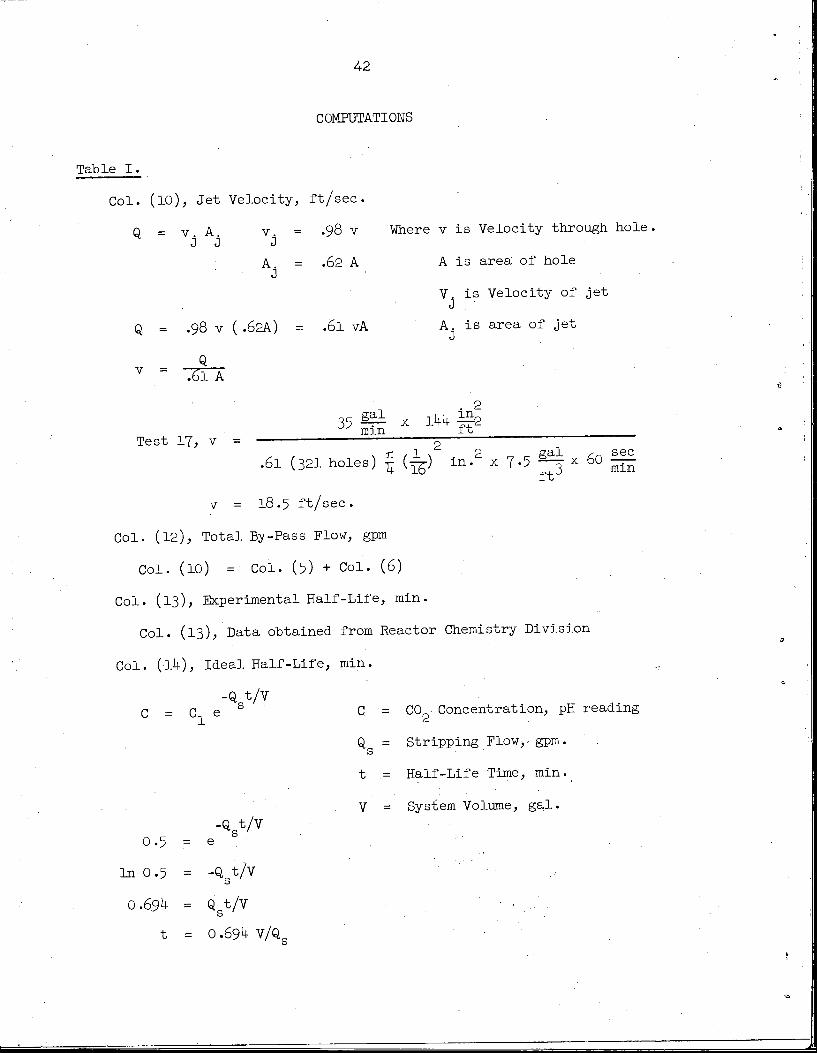
42
COMPUTATIONS
Table I.
Col. (10), Jet Velocity, ft/sec
q = v A v = .98 v Where v is Velocity through hole
A = .62 A A is area of hole
V. is Velocity of jet
Q. = .98 v (.62A) = .61 vA A is area of jet
vQ
.61 A
35s2i x lkk idmm ft
Test 17, v
.61 (321 holes) I(-^) in.2 x7-5 ^ x60
v = 18.5 ft/sec.
Col. (12), Total By-Pass Flow, gpm
Col. (10) = Col. (5) + Col. (6)
Col. (13), Experimental Half-Life, min.
Col. (13), Data obtained from Reactor Chemistry Division
Col. (-Ik), Ideal Half-Life, min.
-Q.t/Vc = c e s C = CO Concentration, pH reading
Q = Stripping Flow,- gpm.s
t = Half-Life Time, min.
V = System Volume, gal.
-Q t/vs
0.5 = e
In 0.5 = -ftt/v
0.6.9^ = Qt/V
t = 0.69^ v/q
sec
ft-' mln

43.
Test 17, t = °'£>9k(88) = lt22min.
Col. (15), Relative Effectiveness, "jo
• col (15) - Co1- [lk]LO±* UW •". Col. (13)
Table II.
Col. (3), Motor Input Power, Kw
Col. (3) = k Col. (2)
Col. (6), Motor Input Power, Kw
mi (6) - Eco1- (4)] [Col. (5)]GO±" [b) ~ 1000
Col. (8), Discharge Head, ft.
Col. (8) - Col. (7)(^§ x^^'/f2 =Col. (7) (2.31)in 62.4- —-
ftJ
Col. (ll), Venturi Pressure Drop, psi
Col. (11) .= Col. (9) -Col. (10)
Col. (13)> Venturi Flow, gpm
Col. (13) obtained from Fig. 7, using Col. (ll) or (12)
Col. (15) and (17), Stripper Flow, gpm
Cols. (15) and (17) = tCols..(l^and (l6)] ^
Col. (l8), Fountain Flow, gpm
Col. (l8) obtained from Fig. 18
Col. (19), Total Flow, gpm
Col. (19) = Col. (13) + Col. (15) + Col. (17) + Col. (18)

44
Col. (20), Change in Velocity Head, ft.
6 ?Col. (20) .=• 1.28.x 10 Q Where Q = Total Flow, gpm.
2g
-6 2 vd Vs ^Adr (Q/A )<1.28 x 10 DQSi-i-'= i_, ^_
* 2g 2g 2g 2g
. 2 .2 _ 2 .2ltd, n&»
16 Qg 1 1 '
•V d *: d S
2(32.2)rt£
Where d = discharge diameter
d = suction diameters
dd .= 0.505 ft.
d = 0.666 ft.
Q ,= ftJ/sec
16^'(7.5 x 60 f 1 1
2(32.2)«2 (.505)^ (.666)k
Col. (20) = 1.28x10 Q Where Q = gpm.
Col. (21), Total Head, ft.
Col. (21) = Col..(8) + Col. (20)
Table III,
Col. (3), Motor Input Power, Kw.
Col. (3) = k [.Col. (2)3

45
Col. (6), Motor Input Power, Kw.
Pol (6) = tCol..(lQ] [co1- (5)]' v ' 1000
Col. (8), Discharge Head, ft.
Col.
Col. (10
Col.
Col. (15
Col.
Col. (16
Col.
Col. (17
Col.
Col. (18
Col.
Col. (19
Col.
Col. (20
Col.
Col. (21
Col
Col. (22
Col
Col. (11) + Col. (12) + Col. (13) + Col. {Ik)100
(8) = Col. (7) (2.31)
), Venturi Flow, gpm.
(10) is obtained from Fig. 7 using Col. (9)
), Stripping Flow, gpm.
(15) =
), Fountain Flow, gpm.
(16) is obtained from Fig. 18.
), Total Flow, gpm.
(17) = Col. (10) + Col. (15) + Col. (16).
), Change in Velocity Head, ft.
(18), Same as Col. (20), Table II.
), Total Head, ft.
(19) .= Col. (8) + Col. (18).
), Pump Power Input, hp.
(20) obtained from Fig. 8, using Col. (6)
), Water Horsepower, hp;.
(21) = ^oTJ Qis in gpm.
H is in ft.
), Efficiency, $
(oo\ - [col- (21)1 mo(22} " [col.., (20)J 10°
17-5


.47
INTERNAL DISTRIBUTION
.1. MSRP Director's Office •2k. A. M. Perry2. R. F. Apple 25. M. W. Rosenthal
3- S. E. Beall 26. H. W. Savagek. M. Bender 27. A. W. Savolainen
5- E. S. Bettis 28. D. Scott
6. F. F. Blankenship 29- M. J. Skinner
7- A. L. Boch ) 30-35- P. G. Smith
8. W. F. Boudreau 36. I. Spiewak
9- R. B. Briggs 37- J. A. Swartout
10. J. M. Coburn 38. A. Taboada •
ll. G. T. Colwell 39. J. R. Tallackson
12. A. P. Fraas kO. D. B. Trauger
13- C. H. Gabbard kl. R. S. Valachovic
.Ik. W. R. Grimes 4-2. J. H. Westsik
15- A. G. Grindell 43. L. V. Wilson
16. M. I. Lundin kk. c. E. Winters
17- R. N. Lyon 4.5-46. Central Research Library18. H. G. MacPherson 4-7-49. ORNL - Y-12 Technical Library,19. W. D. Manly Document Reference Section
20. W. B. McDonald 50-52. Laboratory Records Department21. A.J. Miller 53. Laboratory Records, ORNL R.C.22. R. L. Moore
23- J. C Moyers
EXTERNAL DISTRIBUTION
54-68. Division of Technical Information Extension69* Research and Development Division, ORO
70-71. Reactor Division, ORO