ordering guide budi-1s · budi-1s ordering guide page 1 of 13 issue 3 10-2012 ordering guide of the...
TRANSCRIPT

Ordering Guide
for BUDI-1S product range

BUDI-1S Ordering guide
Page 1 of 13 Issue 3 Issue 3 10-2012
Ordering Guide of the FTTH Building Distribution Enclosure: BUDI-1S
This document provides assistance with the selection of racks for use in FIST applications. It includes the following sections: 1 Product description
2 Ordering Information splice and splice/patch version
2.1 Description
2.2 Accessories
2.2.1 Cable seals and cable termination accessories
2.2.2 Other accessories
2.3 Glands

BUDI-1S Ordering guide
Page 2 of 13 Issue 3 Issue 3 10-2012
1 Product description
The BUDI-1S FIST Splice and FIST Splice-Patch Wall Boxes provide one or more of the following features or functions: management, storage, organization and re-arrangement of optical fibers, connectors, adapters, patchcords, cables, optical components and other network components; the facility to locate and integrate the functions of (passive) optical components, i.e. splicing, splitting. The BUDI wall boxes, including the BUDI-1S are designed to operate in category C (controlled), category G (outdoor ground level) and category A (aerial) as characterized by IEC 61753-1. This covers both indoor and outdoor applications. In the former case this would typically be on the customer’s premises such as building basements, telecommunications equipment rooms, computer rooms, etc. Non-protected locations include pole mountings and external wall sites. The BUDI wall box consists of a bottom part and a cover, with a profiled seal for environmental protection. The protection level against water and dust is IP55. The enclosure us UL listed, UV stable and is made from LSZH plastics. Both the BUDI-1S FIST Splice and FIST Splice-Patch version use FIST as a splice organizer system. For customers that want to use this enclosure for splicing only, the FIST splicing system is integrated using SOSA’s to store and manage splices and FSASA splitter modules for accommodating splitters. If splicing needs to be combined with patching, the same FIST SOSA2 splicing organizer is used in combination with a 16 port (SC or 32 port LC) fixed patch panel. Both versions can be completed with a loose tube loop storage area and wrap around cable ports are available (same as BUDI-S).
BUDI-1S Ordering guide
Page 3 of 13 Issue 3 Issue 3 10-2012
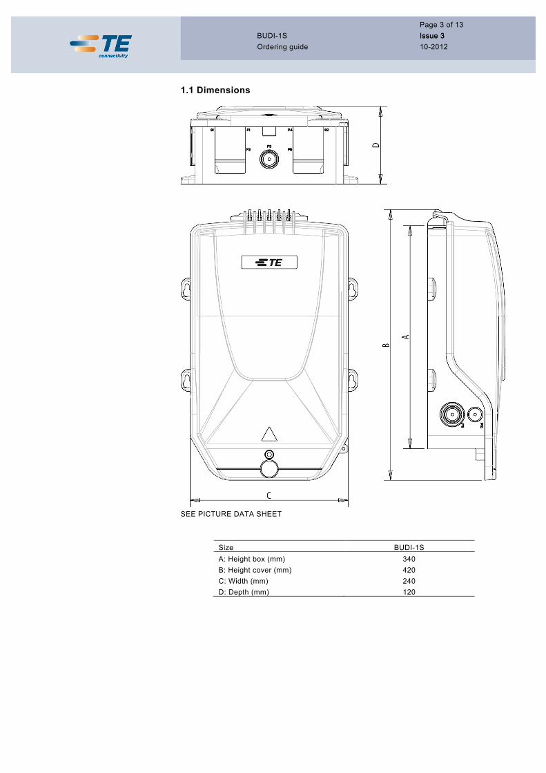
1.1 Dimensions
SEE PICTURE DATA SHEET
Size BUDI-1S A: Height box (mm) 340 B: Height cover (mm) 420 C: Width (mm) 240 D: Depth (mm) 120

BUDI-1S Ordering guide
Page 4 of 13 Issue 3 Issue 3 10-2012
2 Ordering Information
2.1 Description
Both the BUDI-1S splice version and termination version use the FIST-SOSA2 as a splice organizer system using the same flexibility as all FIST products to select multiple types of trays depending on your preferred splice protector and and splice density. The difference between both versions is that the FAS block is moved up to allow a patch panel to be installed but obviously reducing the splice density. For the spliced version, no patch panel is inserted and all available space is used to store splices in a cable to cable configuration. 2.1 Capacities Size BUDI-1S-T BUDI-1S-SP Available UMS for SOSA2 trays 8 16 - with flexible cable tubes 12 20 Splice capacity using SE splice trays 48 96 Splice capacity using SC splice trays (2F/tray) 16 32 Patch capacity SC connector 16 NA Patch capacity LC connector 32 NA Loop cable capability yes yes Non-filled BUDI-1S-X-X Basic content for BUDI-1S-SP-x & BUDI-1S-T-x Box base The cover 4 mounting bolts with seals for wall mounting UMS profile FAS routing block and cap including tube holder(s) and retainers Traylid Velcro strip Tray wedge Patch panel (for the BUDI-1S-T-x only) Installation Instruction Channeling pins Botom ports filled with gland plates
X: T Termination version SP Splice version
X: A No Lock B TE lock and key No 1

BUDI-1S Ordering guide
Page 5 of 13 Issue 3 Issue 3 10-2012
Filled BUDI - 1S - T – X-XX XX XX X X Locking A No lock B With lock ⧣ Adapters and pigtails* 12 16 24 LC only 32 LC only NN No adapters Adapter type* S1 SC/UPC S2 SC/APC L1 LC/UPC L2 LC/APC NN --
Splice holder S SMOUV
N No Splice
Type of tray C FIST-SOSA2-SC E FIST-SOSA2-SE
N No tray
⧣ Splices 16
24 FIST-SOSA2-SE only 32 FIST-SOSA2-SE only
Ex. 24E = 2 FIST-SOSA2-SE trays
* Pigtails and adapters are included in the packaging but not installed in the product

BUDI-1S Ordering guide
Page 6 of 13 Issue 3 Issue 3 10-2012
2.2 Accessories
2.2.1 Cable seals and cable termination accessories
BUDI-1S bottom ports
Port number BUDI-1S
S1 All BUDI-S-SEAL kits S2 All BUDI-S-SEAL kits P1 NA P2 PG16, PG21, PG29 P3 PG16 P4 NA P5 PG16, PG21, PG29
BUDI-S-SEAL-4x10 Wrap around cable seal for 4 cables up to 10mm diameter including:
- cable fixation bracket and tie wraps - seal foam tape
On this bracket one can fix the cables as well with ENSTO strength member fixation devices (separate item FIST-SB/MB-STRBR-01) and with hose clamps with an 8mm band.
BUDI-S-SEAL-4x15 Wrap around cable seal for 4 cables up to 15mm diameter including:
- cable fixation bracket and tie wraps - seal foam tape TE1_4838
On this bracket one can fix the cables as well with ENSTO strength member fixation devices (separate item FIST-SB/MB-STRBR-01) and with hose clamps with an 8mm band.

BUDI-1S Ordering guide
Page 7 of 13 Issue 3 Issue 3 10-2012
BUDI-MINI-BO-FIX01-D15 Component to clip around the TE Mini-Breakout cable to provide cable retention and PICO element fixation when inserted in a standard BUDI seal of D15mm. Box contains 100 clips.
BUDI-S-SEAL-4x15-MINI-N01 Seal + component to clip around the TE Mini-Breakout cable.
BUDI-S-SEAL-2x20 Wrap around cable seal for 2 cables up to 20mm diameter and cable seal for looped cable installation (for spliced version only of the BUDI-S) including:
- cable fixation bracket, hose clamps and strength member fixation plates - seal foam tape

BUDI-1S Ordering guide
Page 8 of 13 Issue 3 Issue 3 10-2012
BUDI-S-SEAL-24x5 Push Through cable seal for 24 cables up to 5mm diameter including:
- cable fixation brackets and tie wraps - cables can be attached individually
BUDI-S-SEAL-24x7 Push Through cable seal for 24 cables up to 7mm diameter including:
- cable fixation brackets and tie wraps - cables are attached in groups of 4 cables
BUDI-S-PTS-48x3 Wrap around pigtail seal for 48 pigtails with a diameter up to 3.5mm (for indoor use only)
- no cable fixation
BUDI-S-PPS-XX XX Seal with integrated patch panel up to 24 connections. For indoor use only. Options: • BUDI-S-PPS-12 S1 (12 SC/UPC standard C grade according to IEC 61755-1) • BUDI-S-PPS-12 S2 (12 SC/APC 8° standard C grade according to IEC 61755-1) • BUDI-S-PPS-24 L1 (24 SC/UPC standard C grade according to IEC 61755-1) • BUDI-S-PPS-24 L2 (24 SC/APC 8° standard C grade according to IEC 61755-1)

BUDI-1S Ordering guide
Page 9 of 13 Issue 3 Issue 3 10-2012
BUDI-1S-LOOPBRCKT-01 Loop bracket to store uncut loose tube overlength in combination with the BUDI-S-SEAL-2x20 cable termination kit.
BUDI-CBL-FIX1-GLD This bracket allows you to fix cables in combination with glands as FIST-GB-GLD-XX. On this bracket one can fix the cables as well with ENSTO strength member fixation devices (separate item FIST-SB/MB-STRBR-01) and with hose clamps with an 8mm band.
BUDI-1S Ordering guide
Page 10 of 13 Issue 3 10-2012
2.3 Glands
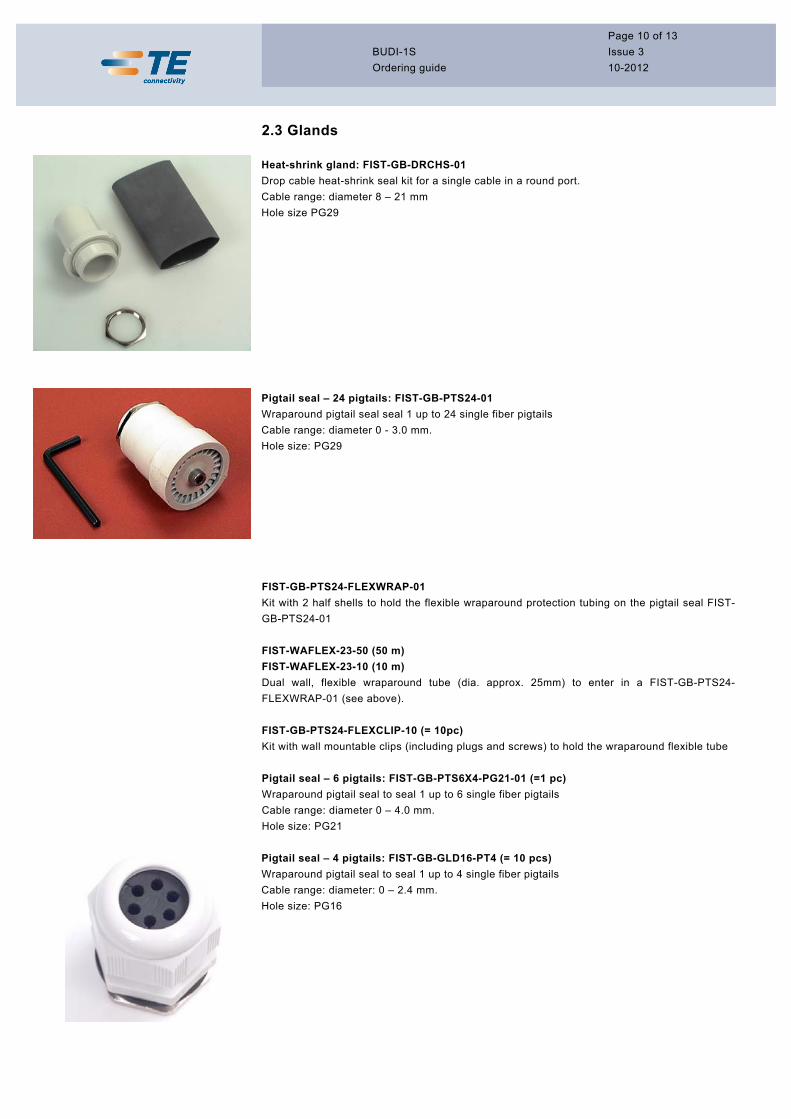
Heat-shrink gland: FIST-GB-DRCHS-01 Drop cable heat-shrink seal kit for a single cable in a round port. Cable range: diameter 8 – 21 mm Hole size PG29
Pigtail seal – 24 pigtails: FIST-GB-PTS24-01 Wraparound pigtail seal seal 1 up to 24 single fiber pigtails Cable range: diameter 0 - 3.0 mm. Hole size: PG29
FIST-GB-PTS24-FLEXWRAP-01 Kit with 2 half shells to hold the flexible wraparound protection tubing on the pigtail seal FIST-GB-PTS24-01 FIST-WAFLEX-23-50 (50 m) FIST-WAFLEX-23-10 (10 m) Dual wall, flexible wraparound tube (dia. approx. 25mm) to enter in a FIST-GB-PTS24-FLEXWRAP-01 (see above). FIST-GB-PTS24-FLEXCLIP-10 (= 10pc) Kit with wall mountable clips (including plugs and screws) to hold the wraparound flexible tube Pigtail seal – 6 pigtails: FIST-GB-PTS6X4-PG21-01 (=1 pc) Wraparound pigtail seal to seal 1 up to 6 single fiber pigtails Cable range: diameter 0 – 4.0 mm. Hole size: PG21
Pigtail seal – 4 pigtails: FIST-GB-GLD16-PT4 (= 10 pcs) Wraparound pigtail seal to seal 1 up to 4 single fiber pigtails Cable range: diameter: 0 – 2.4 mm. Hole size: PG16

BUDI-1S Ordering guide
Page 11 of 13 Issue 3 10-2012
Multiple cable seal: FIST-GB-GLD16-4X4MM (= 10pc) Cable seal to seal up to 4 cables Cable range: diameter 2.4 – 4mm. Hole size: PG16 Multiple cable seal: FIST-GB-GLD21-4X6MM (= 10pc) Cable seal to seal up to 4 cables Cable range: diameter 4 - 6 mm. Hole size: PG21 Multiple cable seal: FIST-GB-GLD21-4X7MM (= 10pc) Cable seal to seal up to 4 cables Cable range: diameter 5 -7 mm. Hole size: PG21 Multiple cable seal: FIST-GB-GLD21-6X5MM (= 10pc) Cable seal to seal up to 6 cables Cable range: diameter 4 -5 mm. Hole size: PG21 Multiple cable seal: FIST-GB-GLD21-8X4MM-10 (= 10pc) Cable seal to seal up to 8 cables Cable range: diameter 2.4 - 4 mm. Hole size: PG21 Multiple cable seal: FIST-GB-GLD29-8X5.5MM (= 10pc) Cable seal to seal up to 8 cables Cable range: diameter 4 - 5.5 mm. Hole size: PG29
Multiple cable seal: FIST-GB-GLD29-4X10MM (= 10pc) Cable seal to seal up to 4 cables Cable range: diameter 8 - 10 mm. Hole size: PG29
Single cable glands: FIST-GB-GLDXX-01 Cable gland size ranges: PG 16 - 6 to 14 mm PG 21 - 9 to 18 mm PG 29 - 15 to 26 mm XX = cable gland size
Flex tube gland: FIST-GB-GLD16-17-FLEX2 (= 10pc) Flex tube gland PG16 for tube with inside diameter 17 mm (FIST-GS-FLEX-17-50-S5027) Hole size: PG16

BUDI-1S Ordering guide
Page 12 of 13 Issue 3 10-2012
Flex tube gland: FIST-GB-GLD16-10-FLEX2 (= 10pc) Flex tube gland PG16 for tube with inside diameter 10 mm (FIST-GS-FLEX-10-50-S5027) Hole size: PG16
2.3.1. Other accessories
Adapters (termination version only) For the BUDI-1S-T patch panel, we use the ADK adapter packs as they are known for many other product lines: OC-ADK-XX-XX-NNCS-(24) XX: S1 SC/UPC S2 SC/APC L1 LC/UPC duplex L2 LC/UPC duplex More options available in the adapter ordering guide
FIST-GB-GRND-02 Grounding feed-through kit (Internal and external grounding wire not included)
BUDI-COVER-PROTECT-LOCK Universal cover to prevent opening BUDI boxes. To be installed only in combination with the TE lock.
FSA-ADK-H1-4 (BUDI-M-TP version only) FSA-ADK-H1-4 (BUDI-M-TP version only) When pigtails are routed out of the box without a patching requirement an aramid strain relief device (KTU) is fitted in the patch panel which can provide strain relief. Each KTU can accommodate: - 2 individual pigtails with maximal diameter of 3.1 mm or - 1 Ribbon4 pigtail or - 1 Ribbon8 pigtail or - 1 Ribbon12 pigtail Maximum 9 retainers (thus 18 KTU’s) can be placed in 1 connector patch panel.

BUDI-1S Ordering guide
Page 13 of 13 Issue 3 10-2012
Adaptors with FIST retainers All information can be found in the datasheet of the optical components section; fiber components; OCA.
Tyco Electronics Raychem bvba Diestsesteenweg 692 B-3010 Kessel-Lo, Belgium Tel.: 32-16-351 011 Fax: 32-16-351 697 www.te.com www.telecomnetworks.com
TE (logo) and TE Connectivity are trademarks of the TE Connectivity group of companies and its licensors.
While TE Connectivity and its affiliates referenced herein have made every reasonable effort to ensure the accuracy of the information contained in this catalog, TE Connectivity cannot assure that this information is error free. For this reason, TE Connectivity does not make any representation or offer any guarantee that such information is accurate, correct, reliable or current. TE Connectivity reserves the right to make any adjustments to the information at any time. TE Connectivity expressly disclaims any implied warranty regarding the information contained herein, including, but not limited to, the implied warranties of merchantability or fitness for a particular purpose. TE Connectivity’ only obligations are those stated in TE Connectivity’ Standard Terms and Conditions of Sale. TE Connectivity will in no case be liable for any incidental, indirect or consequential damages arising from or in connection with, including, but not limited to, the sale, resale, use or misuse of its products. Users should rely on their own judgment to evaluate the suitability of a product for a certain purpose and test each product for its intended application.

TE Connectivity products deliver a competitive
advantage by meeting stringent demands for
performance and reliability.
Innovative TE Connectivity components and
systems are used in telecommunications,
electronics, transportation, infrastructure and
energy networks markets throughout the world.
OG/BUDI-1S/3/10/12
TE (logo) and TE Connectivity are trademarks of the TE Connectivity group of companies and its licensors.
While TE Connectivity and its affiliates referenced herein have made every reasonable effort to ensure the accuracy of the information contained in this catalog, TE Connectivity cannot assure that this information is error free. For this reason, TE Connectivity does not make any representation or offer any guarantee that such information is accurate, correct, reliable or current. TE Connectivity reserves the right to make any adjustments to the information at any time. TE Connectivity expressly disclaims any implied warranty regarding the information contained herein, including, but not limited to, the implied warranties of merchantability or fitness for a particular purpose. TE Connectivity’ only obligations are those stated in TE Connectivity’ Standard Terms and Conditions of Sale. TE Connectivity will in no case be liable for any incidental, indirect or consequential damages arising from or in connection with, including, but not limited to, the sale, resale, use or misuse of its products. Users should rely on their own judgment to evaluate the suitability of a product for a certain purpose and test each product for its intended application.
Tyco Electronics Raychem bvba Diestsesteenweg 692 B-3010 Kessel-Lo, Belgium Tel.: 32-16-351 011 Fax: 32-16-351 697 www.te.com www.telecomnetworks.com