ordering informations - seojin · 2010-09-02 · s t - 1s a1a1a1a1 float type ... b = normal close...
TRANSCRIPT

3
OFF
ON
OFF
ON
OFF
ON
ON
OFF
FUNCTION
NUMBER OF FLOAT
MOUNTING SIZE
1 = 1 Point (Std.)2 = 2 Point3 = 3 Point4 = 4 Point
A = 1 EA (316SS Std.) B = 2 EA (Min. Length 80mm)C = 3 EA (Min. Length 120mm)D = 4 EA (Min. Length 160mm)
1 = PF 1/8 None Housing (Std.)2 = PF 1/4 None Housing3 = PT 3/44 = PT 1OP = etc.
A = 0 ~ 57mm (Std.)B = 0 ~ 100mm C = 0 ~ 200mmD = 0 ~ 300mmE = 0 ~ 1000mm (Max.)
MEASURING PART LENGTH
1= None (Std.)2= ABS Head3= Thermocouple Head(Max.3 point)4= ADC Head(NEMA 4)
HOUSING
WET PART MATERIALA = 304SS (Std.) B = 316SSC = Brass / Nickel platedD = P.P
1 = 316SS (Std.)2 = NBR (Poly-urethane)3 = P.P
FLOAT MATERIAL
MINI FLOAT TYPE LEVEL SWITCH
When order, give us information on exact locations of relay point.
SOL - 1 A 1 A 1 A 1
Overall DimensionsOverall Dimensions
Ordering InformationsOrdering Informations
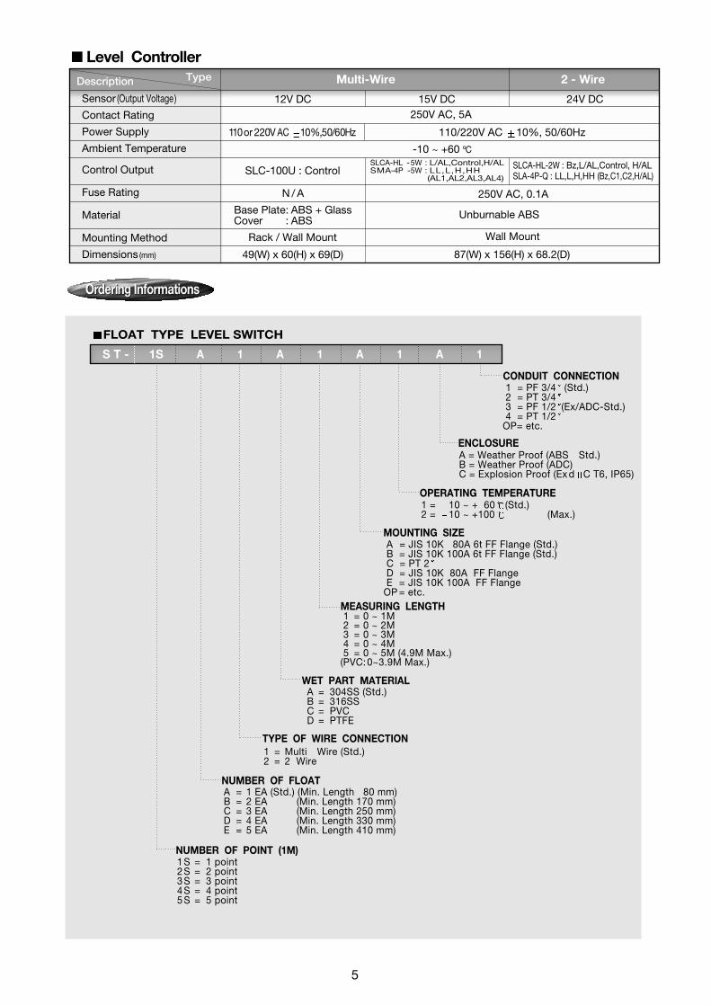
NUMBER OF POINT (1M)
NUMBER OF FLOAT
MEASURING LENGTH
1 S = 1 point 2 S = 2 point 3 S = 3 point 4 S = 4 point 5 S = 5 point
A = 1 EA (Std.) (Min. Length 80 mm)B = 2 EA (Min. Length 170 mm)C = 3 EA (Min. Length 250 mm)D = 4 EA (Min. Length 330 mm)E = 5 EA (Min. Length 410 mm)
1 = 0 ~ 1M2 = 0 ~ 2M3 = 0 ~ 3M4 = 0 ~ 4M5 = 0 ~ 5M (4.9M Max.)
(PVC:0~3.9M Max.)
A = JIS 10K 80A 6t FF Flange (Std.) B = JIS 10K 100A 6t FF Flange (Std.) C = PT 2D = JIS 10K 80A FF FlangeE = JIS 10K 100A FF Flange
OP = etc.
MOUNTING SIZE
1 = 10 ~ + 60 (Std.) 2 = 10 ~ +100 (Max.)
OPERATING TEMPERATURE
A = Weather Proof (ABS Std.) B = Weather Proof (ADC)C = Explosion Proof (Ex d C T6, IP65)
ENCLOSURE
1 = PF 3/4 (Std.) 2 = PT 3/43 = PF 1/2 (Ex/ADC-Std.) 4 = PT 1/2
OP= etc.
CONDUIT CONNECTION
WET PART MATERIALA = 304SS (Std.) B = 316SSC = PVCD = PTFE
1 = Multi Wire (Std.) 2 = 2 Wire
TYPE OF WIRE CONNECTION
S T - 1S A 1 A 1 A 1 A 1
FLOAT TYPE LEVEL SWITCH
Multi-Wire 2 - Wire Description Type
Sensor (Output Voltage)
Contact Rating
Power Supply
Ambient Temperature
Control Output
Fuse Rating
Material
Mounting Method
Dimensions (mm)
12V DC 24V DC15V DC 250V AC, 5A
110/220V AC 10%, 50/60Hz 110or 220V AC 10%,50/60Hz
N / A
-10 ~ +60 ºC
SLC-100U : Control SLCA-HL -5W : L/AL,Control,H/ALSMA-4P -5W : LL,L,H,HH
(AL1,AL2,AL3,AL4)
SLCA-HL-2W : Bz,L/AL,Control, H/ALSLA-4P-Q : LL,L,H,HH (Bz,C1,C2,H/AL)
250V AC, 0.1A
Base Plate: ABS + GlassCover : ABS
Rack / Wall Mount Wall Mount
49(W) x 60(H) x 69(D) 87(W) x 156(H) x 68.2(D)
Unburnable ABS
Level Controller
Ordering Informations Ordering Informations
5

Printed by KOART. 2010. 04 98-CG-002. Rev:7
WET PART MATERIAL
ENCLOSURE
SPECIFIC GRAVITY OF LIQUID
A = 304SS (Std.)B = 316SSC = PVCD = PTFE
1 = JIS 10K 80A 6t FF Flange (Std.)2 = JIS 10K 100A 6t FF Flange (Std.)3 = JIS 10K 80A FF Flange4 = JIS 10K 100A FF Flange5 = PT 2 Socket
OP= etc.
1 = Weather Proof (ABS-Std.)2 = Weather Proof (ADC)3 = Explosion Proof (Ex d llC T6, IP65)
A = 79 (More than 0.85 Std.) : 304SS or 316SSB = 102 (0.6 ~ 0.84) : 316SSC = 95 (Less than 0.59) : 316SSD = 52 (0.65) : 316SSE = 75 (0.5) : PVCF = 50 (0.65) : PVCG = 78.5(0.75) : PTFE
A = PF 3/4 (Std.)B = PT 3/4C = PF 1/2 (Ex/ADC-Std.)D = PT 1/2
OP = etc.
CONDUIT CONNECTION
MEASURING RANGE1 = 0 ~ 1M2 = 0 ~ 2M3 = 0 ~ 3M4 = 0 ~ 4M5 = 0 ~ 5M 6 = 0 ~ 5.9M (Max.)
A = 10 ~ + 60 (Std.)B = 10 ~ +150 (Max.)
OPERATING TEMPERATURE
MOUNTING SIZE
Ordering Informations Ordering Informations
FLOAT TYPE LEVEL TRANSMITTER
ST-600 A 1 A 1 A 1 A
Specifications subject to change without notice.
When placing an order, selected ordering number should be indicated on the purchase order sheet.
8
#91-18 Gunja-dong, Gwangjin-gu, Seoul, KoreaTel: 82-2-2204-8500 Fax: 82-2-466-6445http://www.seojin.biz

1 = 1 Points2 = 2 Points3 = 3 Points4 = 4 Points5 = 5 Points
QUICK FLOAT TYPE LEVEL SWITCH
MATERIAL OF WEIGHT
M = Reed Switch Type, 2 FloatH = Micro Switch Type, 3 FloatC = Mercury Switch Type, 3 FloatE = Mercury Switch Type, 3 316SS Float (A or B Contact)
A = PF 2 ABS Socket Type (Std.)B = PF 2 ABS with JIS 10K 80A FF HDPE FlangeC = PF 2 ABS with JIS 10K 80A FF PVC FlangeD = PF 2 ABS with JIS 10K 100A FF HDPE FlangeE = PF 2 ABS with JIS 10K 100A FF PVC Fange
OP = etc.(ADC Head or Other Flange)ADC Head (Only Muilt-wire)
MOUNTING SIZE (Include Eye-Bolt & Rope)
NUMBER OF FLOAT
TYPE OF SWITCH
A = PVC Std.( 60x110H)B = SUS304 ( 60x 80H)C = SUS316 ( 60x 80H)
OP = etc.
1 = PF (Std.)2 = PT 3 = PF 4 = PT
OP = etc.
CONDUIT CONNECTION
Ordering InformationsOrdering Informations
SQ H 1 A 1 A 1 A 1
OUTPUT
1 = Multi Wire (Std.)2 = 2 -Wire
TYPE OF WIRE CONNECTION
A = Normal Open A Contact (Std.)B = Normal Close B ContactC = Normal Open & Close
1 = 0 ~ 5M(Std.)2 = Cable Extension(SPST per 1M)3 = Cable Extension(SPDT per 1M)
OP = etc.
MEASURING CABLE LENGTH
Printed by KOART. 2010. 04 98-CG-007. Rev: 6
When placing an order, selected ordering number should be indicated on the purchase order sheet.
Specifications subject to change without notice.
12
#91-18 Gunja-dong, Gwangjin-gu, Seoul, KoreaTel: 82-2-2204-8500 Fax: 82-2-466-6445http://www.seojin.biz

STT - S 1 A 1 A 1 A
MEASURING PARTS LENGTH (Cable)
MOUNTING SIZE
HOUSING
ACCESSORY (Clip, Eye-Bolt, U-Bolt, Wire)
CONDUIT CONNECTION
When placing an order, selected ordering number should be indicated on the purchase order sheet.
A = 0 ~ 5 M (Std.) B = 0 ~10M
OP = etc.
DETECTION PARTS MATERIAL1 = 304SS2 = 316SS
TYPE OF PADDLES = Wear Pipe (Std.) X = Cross Paddle 304SST = Flat Paddle 304SS P = Float 304SS
1 = None (Std.)2 = PF 2 ABS Head 3 = JIS 10K 80 A FF HDPE Flange4 = JIS 10K 100A FF HDPE Flange5 = JIS 10K 80A 6T 304SS FF Flange6 = JIS 10K 100A 6T 304SS FF Flange
OP= etc.
A = None (Std.)B = ABS-Head Weather Proof
1 = None (Std.) 2 = Ass’y (5m) 3 = Ass’y (10m)
A = None. B = PF 1/2C = PT 1/2D = PF 3/4
OP = etc.
TILT LEVEL SWITCH
Printed by KOART. 2010. 04 99-CG-005. Rev: 4
Specifications subject to change without notice.
Ordering InformationsOrdering Informations
16
#91-18 Gunja-dong, Gwangjin-gu, Seoul, KoreaTel: 82-2-2204-8500 Fax: 82-2-466-6445http://www.seojin.biz

Ordering InformationsOrdering Informations
Printed by KOART. 2010. 04 98-CG-004. Rev: 7
When placing an order, selected ordering number should be indicated on the purchase order sheet.
Specifications subject to change without notice.
For custom vane models, please supply the following information: pipe size, flow direction,mounting, pressure, temperature, specific gravity and flow rates.
TYPE OF PADDLE
MOUNTING SIZE
WET PART MATERIAL(Tee or welding socket thread)
ENCLOSURE(Housing)
A = 3/4 , 1 (in case PT Std.)B = 1 , 2 , 3 (in case PT 1 Std.) C = 1 , 2 , 3 ,4 , 5 , 6 (in case PT 1 Only)
1 = PT (Std.)2 = PT 1 (Std.)
OP = etc.
3 = Standard type (ABS Resin) 4 = Weather proof (ADC)
A = MBsBE2 & 304SS (Std.)B = 304SS
SF - 3 A 1 A
LIQUID FLOW SWITCH
20
#91-18 Gunja-dong, Gwangjin-gu, Seoul, KoreaTel: 82-2-2204-8500 Fax: 82-2-466-6445http://www.seojin.biz

Printed by KOART. 2010. 04 99-CG-006. Rev: 4
Specifications subject to change without notice.
When placing an order, selected ordering number should be indicated on the purchase order sheet.
250mm to 500mm
501mm to 1000mm
1001mm to 1500mm
Rod Length Operating Differential Mounting Attitude from Vertical
60mm to 350mm
60mm to 850mm
60mm to 1350mm
Up to 10 degrees
Up to 5 degrees
Up to 2 degrees
24
UNIFICATION FLOAT TYPE LEVEL SWITCH
TYPE OF SWITCH
WET PARTS MATERIALA = 304SS + NBR B = 316SS + NBR
CONDUIT CONNECTION
2S = Standard type. Poly Phenole & Poly -carbonate Housing. Atm’ Only (IP64)(1 ‘C’ SPDT. H/L Control. 250V 10A)
SFS - 2S A 1 A 1
MEASURING RANGE1 = Min. 250 ~ 1,000 mm (Std.)2 = 1001 ~ Max. 2,000 mmOP = etc.
MOUNTING SIZEA = PF 3/4B = JIS 5K 50A 2t Special Flange (Std.)
OP = etc.
1 = PF (Std.)2 = PT 3 = PF 4 = PT
OP = etc.
Ordering InformationsOrdering Informations
#91-18 Gunja-dong, Gwangjin-gu, Seoul, KoreaTel: 82-2-2204-8500 Fax: 82-2-466-6445http://www.seojin.biz

CONDUIT CONNECTION
TYPE OF FLOAT
MOUNTING SIZE
MEASURING PART LENGTH
WET PART MATERIAL (FLOAT, WIRE, FLANGE)
OUTPUT
A = PF (Std.)B = PT C = PF D = PT
OP = etc.
When placing an order, selected ordering number should be indicated on the purchase order sheet.
1 = Vertical Type to insert into 3 Pipe2 = Vertical Type to insert into 2 Pipe3 = O.D 10 Horizontal Pipe
A = JIS 10K 80A 6T FF Flange (Std.)B = JIS 10K 100A 6T FF Flange (Std.)C = JIS 10K 80A FF Flange D = JIS 10K 100A FF Flange E = 2 PT Special Socket
OP = etc.
1 = 0 ~ 1 M2 = 0 ~ 2 M3 = 0 ~ 3 M4 = 0 ~ 4 M5 = 0 ~ 5 M (Std.)
6 = 0 ~ 6 M7 = 0 ~ 7 M8 = 0 ~ 8 M9 = 0 ~ 9 M
10 = 0 ~10M (Max.)
A = 304SSB = 316SS
1 = Local Indication only2 = 4 ~ 20mA DC Output (Non local indication)3 = Local Indication & 4 ~ 20 mA DC Output
SGL - 3 A 1 A 1 A
GEAR TYPE LIQUID LEVEL TRANSMITTER
Specifications subject to change without notice.
Printed by KOART. 2010. 04 98-CG-003. Rev: 5
Ordering InformationsOrdering Informations
28
#91-18 Gunja-dong, Gwangjin-gu, Seoul, KoreaTel: 82-2-2204-8500 Fax: 82-2-466-6445http://www.seojin.biz
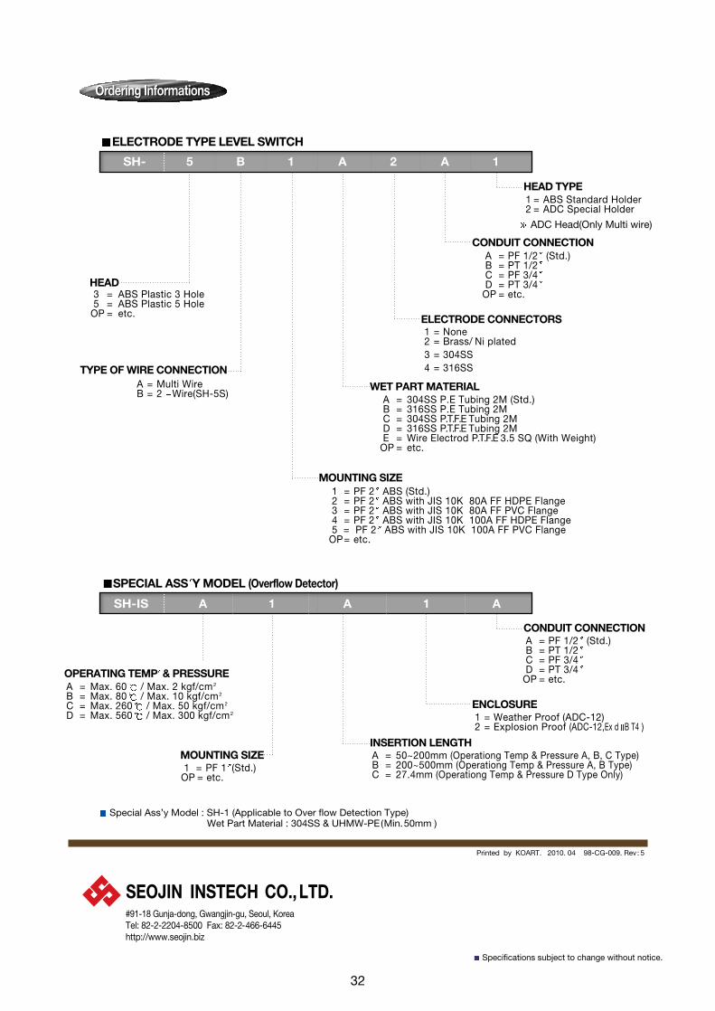
A = Multi WireB = 2 Wire(SH-5S)
ELECTRODE TYPE LEVEL SWITCH
SPECIAL ASS Y MODEL (Overflow Detector)
3 = ABS Plastic 3 Hole5 = ABS Plastic 5 Hole
OP = etc.
1 = None 2 = Brass/ Ni plated 3 = 304SS4 = 316SS
ELECTRODE CONNECTORS
TYPE OF WIRE CONNECTION
HEAD
Ordering InformationsOrdering Informations
SH- 5 B 1 A 2 A 1
MOUNTING SIZE
A = 304SS P.E Tubing 2M (Std.)B = 316SS P.E Tubing 2MC = 304SS P.T.F.E Tubing 2MD = 316SS P.T.F.E Tubing 2M E = Wire Electrod P.T.F.E 3.5 SQ (With Weight)
OP = etc.
WET PART MATERIAL
1 = PF 2 ABS (Std.)2 = PF 2 ABS with JIS 10K 80A FF HDPE Flange3 = PF 2 ABS with JIS 10K 80A FF PVC Flange4 = PF 2 ABS with JIS 10K 100A FF HDPE Flange5 = PF 2 ABS with JIS 10K 100A FF PVC Flange
OP= etc.
A = PF 1/2 (Std.)B = PT 1/2C = PF 3/4D = PT 3/4
OP = etc.
1 = ABS Standard Holder2 = ADC Special Holder
ADC Head(Only Multi wire)
CONDUIT CONNECTION
HEAD TYPE
SH-IS A 1 A 1 A
MOUNTING SIZE A = 50~200mm (Operationg Temp & Pressure A, B, C Type)B = 200~500mm (Operationg Temp & Pressure A, B Type)C = 27.4mm (Operationg Temp & Pressure D Type Only)
INSERTION LENGTH
A = Max. 60 / Max. 2 kgf/cm2
B = Max. 80 / Max. 10 kgf/cm2
C = Max. 260 / Max. 50 kgf/cm2
D = Max. 560 / Max. 300 kgf/cm2
OPERATING TEMP & PRESSURE
1 = PF 1 (Std.)OP = etc.
1 = Weather Proof (ADC-12)2 = Explosion Proof (ADC-12,Ex d B T4 )
A = PF 1/2 (Std.)B = PT 1/2C = PF 3/4D = PT 3/4
OP = etc.
ENCLOSURE
CONDUIT CONNECTION
Printed by KOART. 2010. 04 98-CG-009. Rev: 5
Special Ass’y Model : SH-1 (Applicable to Over flow Detection Type)Wet Part Material : 304SS & UHMW-PE(Min.50mm )
Specifications subject to change without notice.
32
#91-18 Gunja-dong, Gwangjin-gu, Seoul, KoreaTel: 82-2-2204-8500 Fax: 82-2-466-6445http://www.seojin.biz

MINI MAGNETIC FLOAT TYPE LEVEL SWITCH (Reed Switch Type)
FUNCTION
Pipe(Min. I. D.) SFM - 11, 13, 14 : 120mm SFM - 12, 16 : 130mm
Opening for electrical conduit should face down.
From float to tank (Max. Distance)SFM - 11, 12, 13, 16 : 160 mm SFM - 14 : 60 mm + A
( A Value means a distance of extended part )
Float (Min. I. D.) SFM - 11, 12, 13, 16 : 41mm SFM - 14 : 44mm
WET PART MATERIALA = 304SS (Std.)B = 316SS
CONDUIT CONNECTION
11 = 1 SPST (Std.)12 = 1 SPDT (Std.)13 = 1 SPST (Std.) 14 = 1 SPST Extension type ( Max. 300 mm) 16 = 1 SPST Boundary detection type ( Max. 300mm)
SFM - 11 A 1 A 1
Float opening Nozzle Length
Pipe Opening Orientation
MEASURING PART LENGTH1 = 150 mm : SFM - 11, 12 (Std.) 2 = 150 mm : SFM - 13 (Std.)3 = 151~ 300 mm(Max.) : SFM - 14, 16
MOUNTING SIZEA = JIS 5K 40A Flange (SFM 11, 12, 14, 16, Std.)B = PT 1 (SFM 13 Std.)
OP = etc.
1 = PF (Std.)2 = PT 3 = PF 4 = PT
OP = etc.
Ordering InformationsOrdering Informations
Table for Chamber SelectionTable for Chamber Selection
35
P
( ) ( O ) ( )
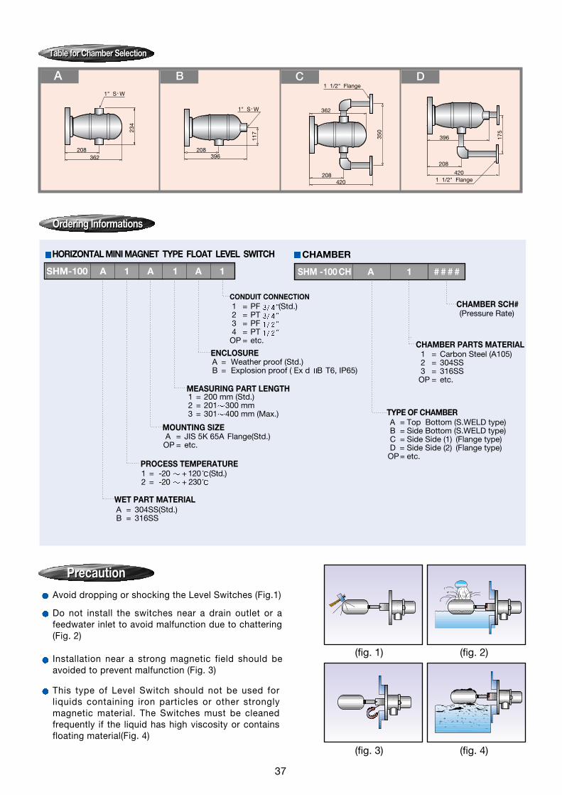
HORIZONTAL MINI MAGNET TYPE FLOAT LEVEL SWITCH
WET PART MATERIAL
PROCESS TEMPERATURE
MOUNTING SIZE
MEASURING PART LENGTH
ENCLOSURE
CONDUIT CONNECTION
A = 304SS(Std.) B = 316SS
1 = -20 + 120 (Std.)2 = -20 + 230
1 = 200 mm (Std.)2 = 201 300 mm3 = 301 400 mm (Max.)
A = JIS 5K 65A Flange(Std.)OP = etc.
A = Weather proof (Std.)B = Explosion proof ( Ex d B T6, IP65)
1 = PF (Std.)2 = PT 3 = PF 4 = PT
OP = etc.
SHM-100 A 1 A 1 A 1
Ordering InformationsOrdering Informations
Table for Chamber SelectionTable for Chamber Selection
PrecautionPrecaution
CHAMBER
TYPE OF CHAMBER
CHAMBER PARTS MATERIAL
CHAMBER SCH#
A = Top Bottom (S.WELD type)B = Side Bottom (S.WELD type)C = Side Side (1) (Flange type)D = Side Side (2) (Flange type)OP= etc.
(Pressure Rate)
1 = Carbon Steel (A105) 2 = 304SS 3 = 316SSOP = etc.
SHM -100 CH A 1 # # # #
Avoid dropping or shocking the Level Switches (Fig.1)
Do not install the switches near a drain outlet or afeedwater inlet to avoid malfunction due to chattering(Fig. 2)
Installation near a strong magnetic field should beavoided to prevent malfunction (Fig. 3)
This type of Level Switch should not be used forliquids containing iron particles or other stronglymagnetic material. The Switches must be cleanedfrequently if the liquid has high viscosity or containsfloating material(Fig. 4)
37

Printed by KOART. 2010. 04 98-CG-001. Rev:6
VERTICAL MAGNET FLOAT TYPE LEVEL SWITCH
A = Weather proof (C.S Cover Std.)B = Explosion proof ( Ex d B T4, IP65)
ENCLOSURE
A = 304SSB = 316SSC = Carbon Steel
OP = etc.
1 = PF (Std.)2 = PT 3 = PF 4 = PT
OP = etc.
WET PART MATERIAL
A = JIS 10K 80A FF Flange(Std.) B = JIS 10K 100A FF FlangeC = ANSI 3 150lb RF FlangeD = ANSI 4 150lb RF FlangeE = JIS & ANSI 5” (Chamber type only)
OP = etc.
MOUNTING SIZE
1 = 1 SPDT2 = 1 DPDT
OUTPUT
CONDUIT CONNECTION
1 = 25 ~ +1502 = 25 ~ +2303 = 25 ~ +350
PROCESS TEMPERATURE
Ordering InformationsOrdering Informations
CHAMBER
1 = Carbon Steel 2 = 304SS3 = 316SS
OP = etc.
CHAMBER PARTS MATERIAL
(Pressure Rate)
A = Top Bottom (S.Weld type)B = Side Bottom (S.Weld type)C = Side Side(1) (Flange type) C = Side Side(2) (Flange type)
OP = etc.
TYPE OF CHAMBER
CHAMBER SCH# (STD. 5”/125A)
SHM-2000CH A 1 # # # #
SHM-2000 A 1 A 1 A 1
When placing an order, selected ordering number should be indicated on the purchase order sheet.
Specifications subject to change without notice.
40
#91-18 Gunja-dong, Gwangjin-gu, Seoul, KoreaTel: 82-2-2204-8500 Fax: 82-2-466-6445http://www.seojin.biz

A = 40 ~ +120 & 10Kgf/Cm2 (Std.)B = 40 ~ +230 & 30Kgf/Cm2 (1S, 2S)C = 40 ~ +230 & 30Kgf/Cm2 (3S)D = 40 ~ +230 & 30Kgf/Cm2 (4S)
DISPLACEMENT TYPE LEVEL SWITCH
1 = 304SS (Std.) 2 = 316SS3 = Monel (Special Option)
1 = 1 point (Alarm)2 = 1 point (Alarm DPDT) 3 = 2 point (Alarm)4 = 2 point (Alarm DPDT)5 = 2 point (Control)6 = 2 point (Control DPDT)7 = 3 point (Alarm, Control)8 = 3 point (Alarm, Control DPDT)
9 ~14 : only weather proof
9 = 3 point (HH/H/L/LL Alarm SPDT)10 = 3 point (HH/H/L/LL Alarm DPDT)11 = 4 point (H/L Alarm & Control SPDT)12 = 4 point (H/L Alarm & Control DPDT)13 = 4 point (HH/H/L/LL Alarm SPDT)14 = 4 point (HH/H/L/LL Alarm DPDT)15 = 4 point (2 Control SPDT)16 = 4 point (2 Control DPDT)
A = JIS 10K 80A 304SS 6t Flange (Std.) B = JIS 10K 100A 304SS 6t Flange (Std.) C = JIS 10K 80A FF C.S Flange D = JIS 10K 100A FF C.S Flange E = JIS 10K 80A FF 304SS Flange F = JIS 10K 100A FF 304SS Flange
OP = etc.
A = PF (Std.) B = PT C = PF D = PT
OP = etc.
CONDUIT CONNECTION
1 = Weather proof (Std.) C.S Cover2 = Weather proof CAL Cover 3 = Explosion proof ( Ex d IIC, IP65) CAL Cover
ENCLOSURE
MOUNTING SIZE
WET PART MATERIAL
OPERATING TEMP’ & PRESSURE
NUMBER OF CONTACT FOR CONTROL
Ordering InformationsOrdering Informations
CHAMBER
1 = Carbon steel (A105) 2 = 304SS3 = 316SS
OP = etc.
A = 300mmB = 500mmC = 600mmD = 800mmE = 1,000mm
OP = etc.
(Pressure Rate)
1 = Side Side (Flange type)2 = Side Side (Socket type)3 = Side Bottom (Flange type)4 = Side Bottom (Socket type)
OP= etc.
TYPE OF CHAMBER
CHAMBER SCH #
C TO C (Carbon Steel)
CHAMBER PARTS MATERIAL
SMC - 1 A 1 A 1 A
SMC - CH 1 A 1 # # # # #
46
Printed by KOART. 2010. 04 98-CG-006. Rev:0
Specifications subject to change without notice.
#91-18 Gunja-dong, Gwangjin-gu, Seoul, KoreaTel: 82-2-2204-8500 Fax: 82-2-466-6445http://www.seojin.biz

52
Ordering InformationsOrdering Informations
Vertical Float Type Level Switch (4 Bottle Seal Type - Max. Pressure : 46Bar)
SMC - 73 B 1 A 1 A 1 A 1 A 1 A
PROCESS TEMP'(CONTACT RATING)A = Max.120 (10A 250V AC / 0.6A 125V DC) B = Max.230 (5A 250V AC / 0.5A 125V DC) C = Max.400 (1A 250V AC / 1A 30V DC) D = Max.230 (15A 250V AC / 1A 125V DC) E = Max.400 (1A 115V AC / 3A 28V DC)
(Hermetical Seal Type)
PROCESS CONNECTION TYPE1 = Side-Bottom(Socket Welding)(Std.) 2 = Side-Side(Socket Welding) 3 = Side-Side(Elbow Type, Socket Welding) 4 = Side-Side(Tee Type, Socket Welding)
A = MFR Std.(SEOJIN Spec.)OP = etc.(Customer Requirements)
PAINTING
1 = NONEOP = etc.
DRAIN PARTS
A = PF 3/4 (Std.)B = PT 3/4
OP = etc.
CONDUIT CONNECTION
1 = Carbon Steel(Std.) 2 = 304 SS 3 = 316 SS
CHAMBER MATERIAL
A = 316 SS(Std.) FLOAT MATERIAL
1 = 1 SPDT2 = 1 DPDT (2 SPDT)
SNAP SWITCH ACTION (OUTPUT)
B = 4 Bottle Seal Type(Max. Temp : 400 , Max. Press : 46 Bar)
MODEL SELECTION
1 = Weather Proof (Std., IP65, C.S Cover)2 = Explosion Proof (Ex d llC T6, IP65)
ENCLOSURE
A = 1 S.W(Std.) B = 3/4 S.W
PROCESS CONNECTION SIZE
TYPE 1(STD) TYPE 2 TYPE 3 TYPE 4
117
108
90
SMC-73B 4 Bottle Seal Type
53
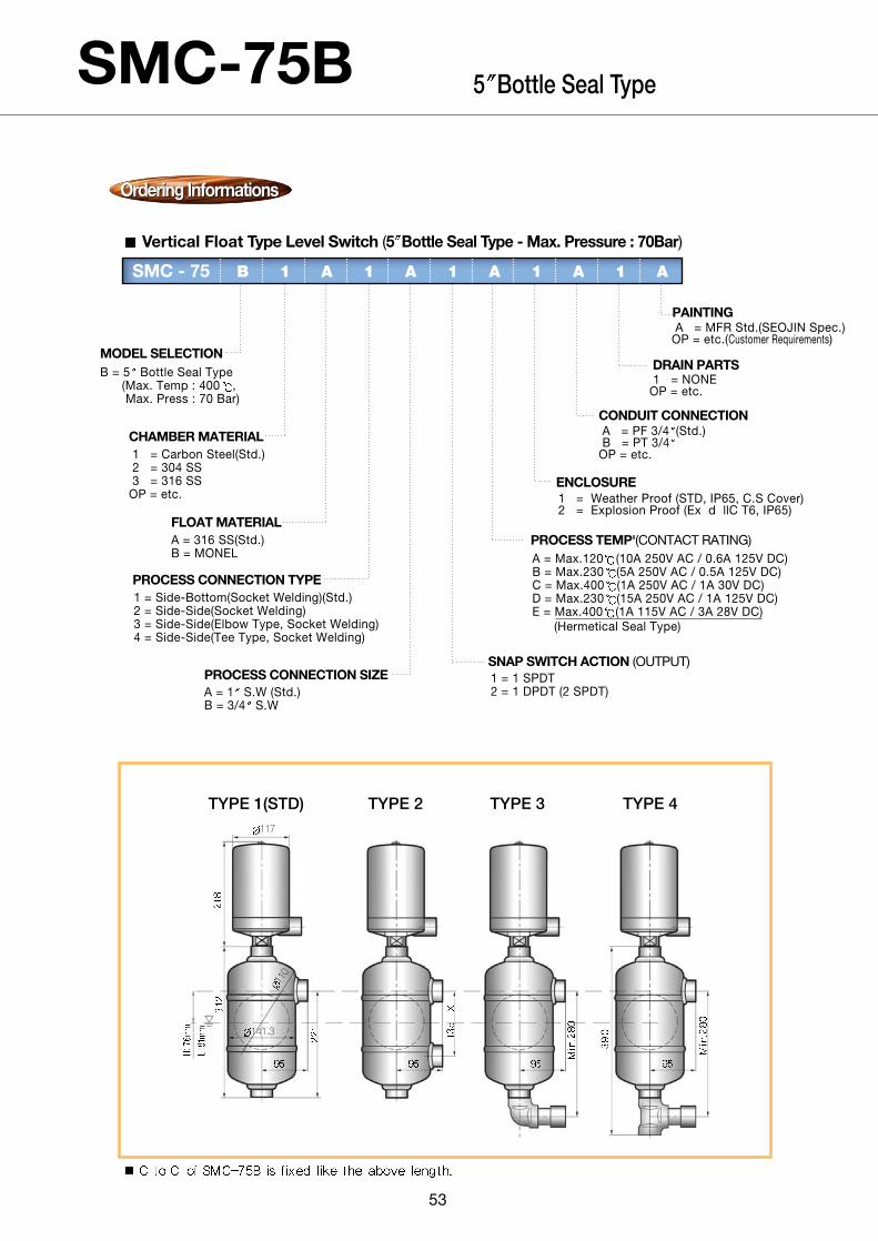
Ordering InformationsOrdering Informations
Vertical Float Type Level Switch (5 Bottle Seal Type - Max. Pressure : 70Bar)
SMC - 75 B 1 A 1 A 1 A 1 A 1 A
PROCESS TEMP'(CONTACT RATING)A = Max.120 (10A 250V AC / 0.6A 125V DC) B = Max.230 (5A 250V AC / 0.5A 125V DC) C = Max.400 (1A 250V AC / 1A 30V DC) D = Max.230 (15A 250V AC / 1A 125V DC) E = Max.400 (1A 115V AC / 3A 28V DC)
(Hermetical Seal Type)
PROCESS CONNECTION TYPE1 = Side-Bottom(Socket Welding)(Std.) 2 = Side-Side(Socket Welding) 3 = Side-Side(Elbow Type, Socket Welding) 4 = Side-Side(Tee Type, Socket Welding)
A = MFR Std.(SEOJIN Spec.)OP = etc.(Customer Requirements)
PAINTING
1 = NONEOP = etc.
DRAIN PARTS
A = PF 3/4 (Std.)B = PT 3/4
OP = etc.
CONDUIT CONNECTION
1 = Carbon Steel(Std.) 2 = 304 SS 3 = 316 SS
OP = etc.
CHAMBER MATERIAL
A = 316 SS(Std.) B = MONEL
FLOAT MATERIAL
1 = 1 SPDT2 = 1 DPDT (2 SPDT)
SNAP SWITCH ACTION (OUTPUT)
B = 5 Bottle Seal Type(Max. Temp : 400 , Max. Press : 70 Bar)
MODEL SELECTION
1 = Weather Proof (STD, IP65, C.S Cover)2 = Explosion Proof (Ex d llC T6, IP65)
ENCLOSURE
A = 1 S.W (Std.) B = 3/4 S.W
PROCESS CONNECTION SIZE
TYPE 1(STD) TYPE 2 TYPE 3 TYPE 4117
141.3
110
SMC-75B 5 Bottle Seal Type

54
Ordering InformationsOrdering Informations
Vertical Float Type Level Switch (5 Flange Type)
SMC - 75 F 1 A 1 A 1 A 1
PROCESS TEMP'(CONTACT RATING)1 = Max.120 (10A 250V AC / 0.6A 125V DC) 2 = Max.230 (5A 250V AC / 0.5A 125V DC) 3 = Max.400 (1A 250V AC / 1A 30V DC) 4 = Max.230 (15A 250V AC / 1A 125V DC) 5 = Max.400 (1A 115V AC / 3A 28V DC)
(Hermetical Seal Type)
MOUNTING TYPEA = 5 150# ANSI RF Flange(Std.) B = 5 300# ANSI RF FlangeC = 5 600# ANSI RF FlangeD = 5 900# ANSI RF FlangeE = 5 1500# ANSI RF Flange
OP = etc.
1 = PF 3/4 (Std.)2 = PT 3/4
OP = etc.
CONDUIT CONNECTION
1 = 316 SS(Std.) 2 = MONEL
FLOAT MATERIAL
A = 1 SPDTB = 1 DPDT
SNAP SWITCH ACTION (OUTPUT)
F = 5 Bottle Flange Type (Max. Temp:400 , Max. Press:70 Bar)
MODEL SELECTION
A = Weather Proof (Std., IP65, C.S Cover)B = Explosion Proof (Ex d llC T6, IP65)
ENCLOSURE
1 = 180mm (Std., External Cage of SEOJIN INSTECH) 2 = 150 ~ 300mm (Tank Top Mounting Length = Min. 150mm)
SETPOINT
110
SMC-75F 5 Flange Type
55
Ordering InformationsOrdering Informations
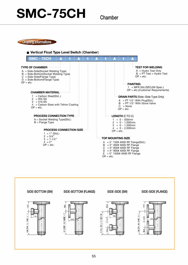
Vertical Float Type Level Switch (Chamber)
SMC - 75CH A 1 A 1 A 1 A 1 A
LENGTH (CTO C)1 = 0 ~ 500mm2 = 0 ~ 1,000mm3 = 0 ~ 1,500mm4 = 0 ~ 2,000mm
OP = etc.
PROCESS CONNECTION TYPEA = Socket Welding Type(Std.)B = Flange Type
A = Hydro Test OnlyB = PT Test + Hydro Test
OP = etc.
TEST FOR WELDING
1 = MFR Std.(SEOJIN Spec.)OP = etc.(Customer Requirements)
PAINTING
1 = Carbon Steel(Std..)2 = 304 SS3 = 316 SS4 = Carbon Steel with Tefron Coating
OP = etc.
CHAMBER MATERIAL
A = 5 150# ANSI RF Flange(Std.)B = 5 300# ANSI RF FlangeC = 5 600# ANSI RF FlangeD = 5 900# ANSI RF FlangeE = 5 1500# ANSI RF Flange
OP = etc.
TOP MOUNTING SIZE
A = Side-Side(Socket Welding Type)B = Side-Bottom(Socket Welding Type)C = Side-Side(Flange Type)D = Side-Bottom(Flange Type)
OP = etc.
TYPE OF CHAMBER
A = PT 1/2 With Plug(Std.)B = PT 1/2 With Glove ValveC = None
OP = etc.
DRAIN PARTS (Side -Side Type Only)
1 = 1 (Std.) 2 = 3/43 = 1-1/24 = 2
OP = etc.
PROCESS CONNECTION SIZE
SIDE-BOTTOM (SW) SIDE-BOTTOM (FLANGE) SIDE-SIDE (SW) SIDE-SIDE (FLANGE)
SMC-75CH Chamber
Printed by KOART. 2010. 04 98-CG-006-1. Rev:0
Specifications subject to change without notice.
#91-18 Gunja-dong, Gwangjin-gu, Seoul, KoreaTel: 82-2-2204-8500 Fax: 82-2-466-6445http://www.seojin.biz
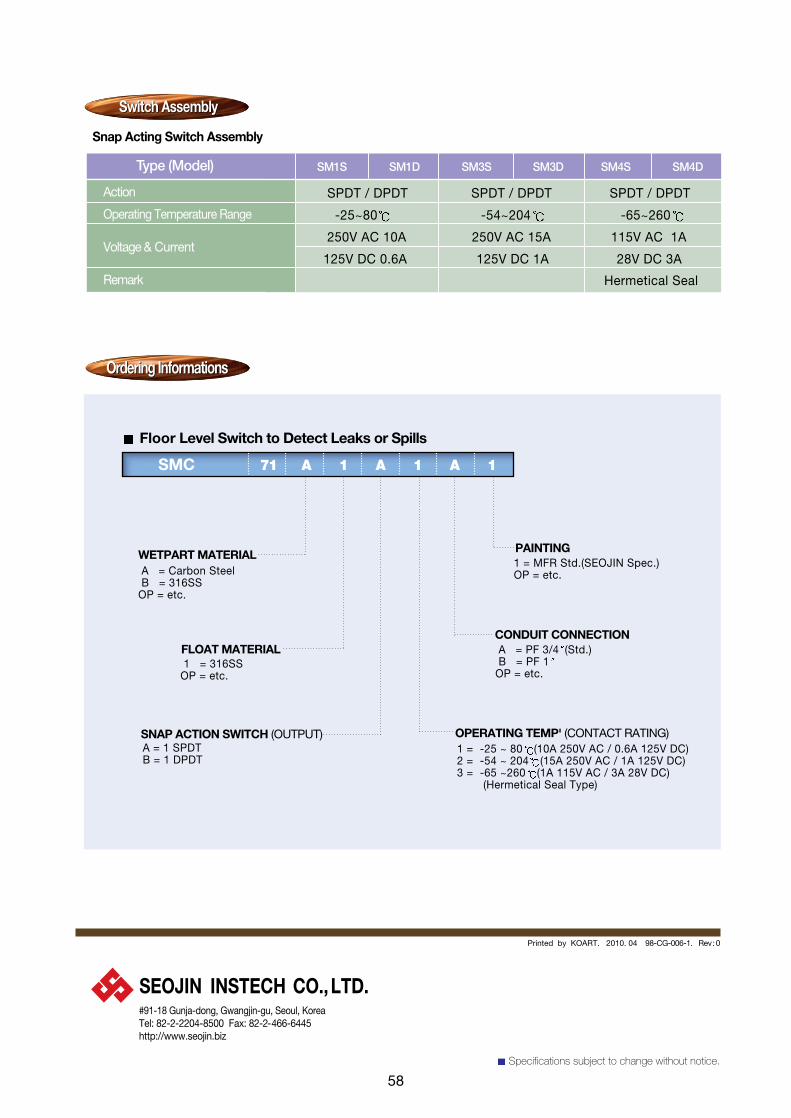
Switch AssemblySwitch Assembly
Snap Acting Switch Assembly
Type (Model) SM1S SM1D SM3S SM3D SM4S SM4D
Action
Operating Temperature Range
Voltage & Current
Remark
SPDT / DPDT SPDT / DPDT SPDT / DPDT
-25~80 -54~204 -65~260
250V AC 10A 250V AC 15A 115V AC 1A
125V DC 0.6A 125V DC 1A 28V DC 3A
Ordering InformationsOrdering Informations
Floor Level Switch to Detect Leaks or Spills
SMC 71 A 1 A 1 A 1
1 = MFR Std.(SEOJIN Spec.)OP = etc.
PAINTING
A = PF 3/4 (Std.)B = PF 1
OP = etc.
CONDUIT CONNECTION
1 = 316SSOP = etc.
FLOAT MATERIAL
A = Carbon SteelB = 316SS
OP = etc.
WETPART MATERIAL
A = 1 SPDTB = 1 DPDT
SNAP ACTION SWITCH (OUTPUT) OPERATING TEMP' (CONTACT RATING)1 = -25 ~ 80 (10A 250V AC / 0.6A 125V DC) 2 = -54 ~ 204 (15A 250V AC / 1A 125V DC) 3 = -65 ~260 (1A 115V AC / 3A 28V DC)
(Hermetical Seal Type)
Hermetical Seal
58

65
Ordering InformationsOrdering Informations
Torque Tube, Displacement Type Level Transmitter Chamber
SDT-420 CH A 1 A 1 A 1 A 1 A 1
PROCESS CONNECTION TYPE
1 = 2"(Std.)2 = 1-1/2"3 = 1"
OP = etc.
PROCESS CONNECTION SIZE
A = Side-SideB = Side-BottomC = Top-Bottom
OP= etc.
TYPE OF CHAMBER
A = 3" ANSI RF(Std.)B = 3" ANSI RJFC = 4" ANSI RFD = 4" ANSI RJF
TOP MOUNTING SIZE
LENGTH (C to C)A = 300 ~ 350mmB = 351 ~ 500mmC = 501 ~ 750mmD = 751 ~ 1,200mmE = 1,201 ~ 2,000mmF = 2,001 ~ 3,000mmG= 3,001 ~ 4,000mmH = 4,001 ~ 5,000mm
1 = Hydro Test Only2 = PT Test + Hydro Test
OP = etc.(Customer Requirements)
TEST FOR WELDING
A = MFR Std.(SEOJIN Spec.)OP = etc.(Customer Requirements)
PAINTING
1 = 150#2 = 300#3 = 600#4 = 900#
OP= etc.
PRESSURE RATING
1 = PT 1/2" With Plug(Std.)2 = PT 1/2" With Globe Valve
OP = etc.
DRAIN PARTS (Side-Side Type Only)1 = Carbon Steel(Std.)2 = 304 SS3 = 316 SS
OP = etc.
A = Socket Welding TypeB = Flange Type
OP = etc.
CHAMBER MATERIAL
TYPE A (SIDE-SIDE) TYPE B (SIDE-BOTTOM) TYPE C (TOP-BOTTOM)

66
Printed by KOART. 2010. 04 99-CG-002. Rev: 2
Specifications subject to change without notice.
#91-18 Gunja-dong, Gwangjin-gu, Seoul, KoreaTel: 82-2-2204-8500 Fax: 82-2-466-6445http://www.seojin.biz
Ordering InformationsOrdering Informations
Torque Tube, Displacement Type Level Transmitter
SDT-420 A 1 A 1 A 1 A 1 A31
MOUNTING DIRECTIONA = Righthand Mounted(Std.) B = Lefthand Mounted
MEASURING PARTS LENGTH(C TO C)1)1 = 300 ~ 350mm 2 = 351 ~ 500mm 3 = 501 ~ 750mm 4 = 751 ~ 1,200mm5 = 1,201 ~ 2,000mm 6 = 2,001 ~ 3,000mm 7 = 3,001 ~ 4,000mm 8 = 4,001 ~ 5,000mm
A = 304SS Tag Fixed On AmplifierB = 304SS Tag Fixed With Wire
TAGGING METHOD
1 = Weather Proof (IP65) 2 = Explosion Proof (Ex d IIC T6/IP65 : KOSHA)3 = Intrinsic Safety (Ex ia IIC T4 /IP65 : KTL)
ELECTRICAL CLASSIFICATION(ENCLOSURE)
A = 316L(Std.)B = PTFEC = etc.
DISPLACER MATERIAL
1 = Carbon Steel (Std.) 2 = 316LSS
OP = etc.
TORSION BAR GUARD MATERIAL
A = RF Raised Face Flange(available with 31, 33, 36, 41, 43, 46, 49) B = RJF Ring Joint Flange(available with 33, 36, 39, 43, 46, 49)
OP = etc.
TORSION BAR GUARD CONTACT FACE
31 = 3" 150# ANSI (Std.)33 = 3" 300# ANSI 36 = 3" 600# ANSI 39 = 3" 900# ANSI 41 = 4" 150# ANSI 43 = 4" 300# ANSI 46 = 4" 600# ANSI 49 = 4" 900# ANSI OP = etc. NOTE : 1) Displacer length is measuring parts length + 30mm
TORSION BAR GUARD MOUNTING SIZE(Flange Size & Rating)
1 = PF 1/2"(Without Cable Gland)2 = PT 1/2"(With Cable Gland) 3 = NPT 1/2"(With Cable Gland)
OP = etc.
CONDUIT CONNECTION
A = 316 SS(Std.)B = INCONEL 600
OP = etc.
TORQUE TUBE MATERIAL

SFP - 1A A 1 A 1
TYPE OF SENSING PARTS
MEASURING CHAMBER MATERIAL & LENGTH
MOUNTING SIZE
ENCLOSURE
CONDUIT CONNECTION
When placing an order, selected ordering number should be indicated on the purchase order sheet.
1A = Standard type. Atm Only. Neoprene diaphragm. NEMA4. ADC1S = Fluoric rubber(Biton) diaphragm3 = Economic type. Non weather proof. Phenol + C.S Cover
A = None(Std.)B = 304SS 1 Pipe PT 1/2 (Std. Per 1,000mm) C = PVC 1 Pipe PT 1/2 (Per 1,000mm) OP = etc. (Special Diameter & Special Material)
1 = PF 1 Only(Std.)OP = etc.
A = Weather ProofB = Explosion Proof (d2 G4): 500E Type
1 = PF 1/2 (Std.)2 = PT 1/23 = PF 3/44 = PT 3/4OP= etc.
PNEUMATIC TYPE LEVEL SWITCH
Printed by KOART. 2010. 04 99-CG-007. Rev: 2
Specifications subject to change without notice.
Ordering InformationsOrdering Informations
70
#91-18 Gunja-dong, Gwangjin-gu, Seoul, KoreaTel: 82-2-2204-8500 Fax: 82-2-466-6445http://www.seojin.biz
Ordering InformationsOrdering Informations
Printed by KOART. 2010. 04 99-CG-003. Rev: 5
When placing an order, selected ordering number should be indicated on the purchase order sheet.
Specifications subject to change without notice.
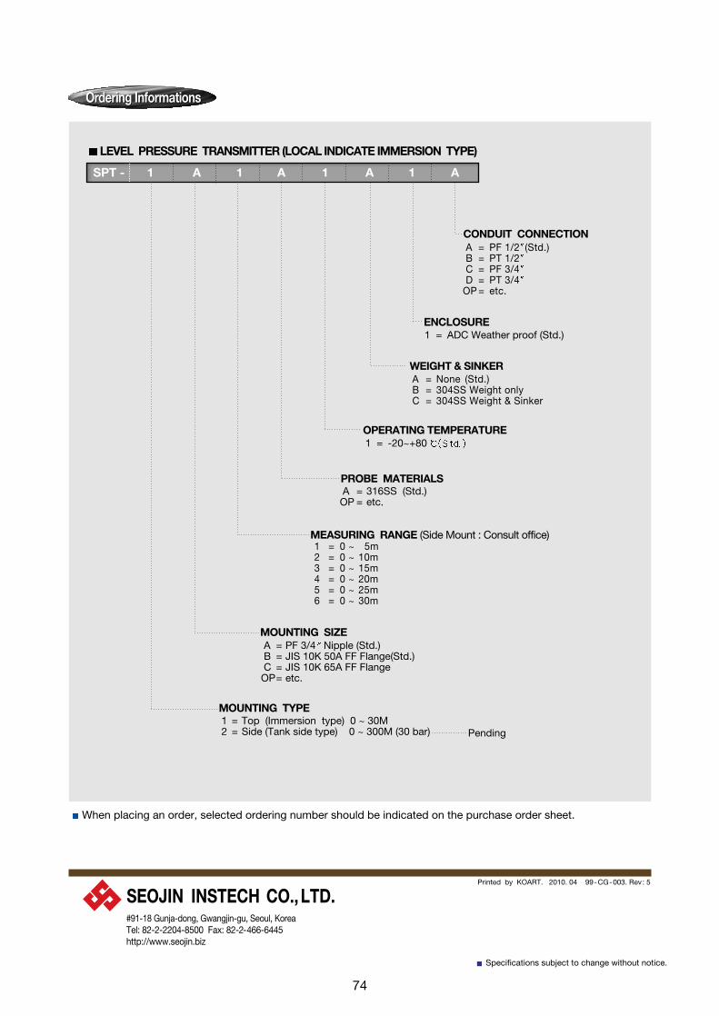
1 = 0 ~ 5m 2 = 0 ~ 10m3 = 0 ~ 15m4 = 0 ~ 20m 5 = 0 ~ 25m 6 = 0 ~ 30m
1 = Top (Immersion type) 0 ~ 30M2 = Side (Tank side type) 0 ~ 300M (30 bar) Pending
MEASURING RANGE (Side Mount : Consult office)
MOUNTING TYPE
SPT - 1 A 1 A 1 A 1 A
MOUNTING SIZE
A = 316SS (Std.)OP = etc.
PROBE MATERIALS
A = PF 3/4 Nipple (Std.) B = JIS 10K 50A FF Flange(Std.) C = JIS 10K 65A FF FlangeOP= etc.
A = None (Std.)B = 304SS Weight onlyC = 304SS Weight & Sinker
WEIGHT & SINKER
1 = ADC Weather proof (Std.)
A = PF 1/2 (Std.) B = PT 1/2C = PF 3/4D = PT 3/4
OP = etc.
ENCLOSURE
1 = -20~+80OPERATING TEMPERATURE
CONDUIT CONNECTION
LEVEL PRESSURE TRANSMITTER (LOCAL INDICATE IMMERSION TYPE)
74
#91-18 Gunja-dong, Gwangjin-gu, Seoul, KoreaTel: 82-2-2204-8500 Fax: 82-2-466-6445http://www.seojin.biz

A = 2 Wire (Std.)B = 3 Wire NOHKEN ProductsOP = etc.
76
Printed by KOART. 2010. 04 99-CG-003-1. Rev:2
When placing an order, selected ordering number should be indicated on the purchase order sheet.
General cable length : Measuring range + 2m only
Ordering InformationsOrdering Informations
1 = 0 ~ 5M2 = 0 ~ 10M3 = 0 ~ 15M4 = 0 ~ 20M5 = 0 ~ 25M 6 = 0 ~ 30M
OP = etc.
1 = TOP (Immersion type) 0-30M 2 = Side (Tank side type) 0-300M(30bar) Pending
1 = None. (Std.)2 = 304SS Weight only 3 = 304SS Weight & Sinker
WEIGHT & SINKER
MEASURING LENGTH (DEPTH)
MOUNTING TYPE
SPL 1 A 1 A 1 A 10
MOUNTING SIZE & JUNCTION BOX
TYPE OF WIRING
A = None.B = JIS 10K 80A 6t FF Flange + ABS (Std.)C = JIS 10K 100A 6t FF Flange + ABS (Std.)D = JIS 10K 80A 6t FF Flange + ADC E = JIS 10K 100A 6t FF Flange + ADC
OP = etc.
A = None. (Std.) B = PF 3/4 (Std.)C = PT 3/4D = PF 1/2E = PT 1/2
OP = etc.
( )M Per 1m
CONDUIT CONNECTION
CABLE EXTENSION
Specifications subject to change without notice.
IMMERSION TYPE LEVEL TRANSMITTER
#91-18 Gunja-dong, Gwangjin-gu, Seoul, KoreaTel: 82-2-2204-8500 Fax: 82-2-466-6445http://www.seojin.biz

Printed by KOART. 2010. 04 98-CG-005. Rev: 4
When placing an order, selected ordering number should be indicated on the purchase order sheet.
Ordering InformationsOrdering Informations
1 = 304SS (Std.) 2 = 316SS
1100 = Local dial indicator (NO transmitter)2200 = 4~20mA DC output ( Transmitter)3300 = 1~8 point Alarm output (Switch)4400 = Alarm & 4~20mADC output ( Transmitter)11SP = Local dial indicator (NO Transmitter) Seal Pipe Option Type22SP = 4~20mA DC output (Transmitter)33SP = H/L point Alarm Output (Switch) 44SP = H/L Alarm & 4~20mA Output (Transmitter)
1 = 3 M 2 = 5 M(Std.)3 = 6 M4 = 10M5 = 12M6 = 15M 7 = 20M(Max.)
MEASURING PART LENGTH
WET PART MATERIAL ( Include in Float, Bottom piece, Guide wire)
OUT PUT
SLT - 2200 A 1 A 1 A 1 A
ALARM CONTACT
A = PT 1 1/2 Socket (Std.) B = NPT 1 1/2 SocketC = JIS 10K 40A FF 304SS Flange (7EA)
OP= etc.
MOUNTING SIZE
A = NoneB = 2 PointC = 4 PointD = 6 PointE = 8 Point
A = Side mount (Std.) B = Top mount
1 = Weather proof (Std.) 2 = Explosion proof (Ex d llB T6)
MOUNTING METHOD
ENCLOSURE
Specifications subject to change without notice.
A = PF 3/4 (Std.) B = PT 3/4C = PF 1/2D = PT 1/2
OP = etc.
CONDUIT CONNECTION
LIQUID TANK LEVEL GAUGE
84
#91-18 Gunja-dong, Gwangjin-gu, Seoul, KoreaTel: 82-2-2204-8500 Fax: 82-2-466-6445http://www.seojin.biz

Ordering InformationsOrdering Informations
Printed by KOART. 2010. 04 98-CG-007. Rev: 6
When placing an order, selected ordering number should be indicated on the purchase order sheet.
Special Ass y Model : High Sensitivity Version
Specifications subject to change without notice.
A = PT 1 (STD)B = PT 1C = PT 2D = JIS 5K 50A FF Flange
OP = etc.
NEW VIBRATION TYPE LEVEL SWITCH
15 = Standard Type (270mm, STD)25 = Probe Extension Type (330~4,000mm)35 = Flexible Tube Extension Type (600~6,000mm)
1 = Weather Proof (STD)2 = Explosion Proof (Ex d llC T6, IP65)
ENCLOSURE
MOUNTING SIZE
PROBE TYPE
SVL - 15 A 1 A 1 A 1
OPERATING TEMPERATURE
A = 270mm (SVL-15 STD) B = Less than 500mm (SVL-25)C = Less than 1,000mm (SVL-25)D = Less than 2,000mm (SVL-25)E = Less than 3,000mm (SVL-25)F = Less than 4,000mm (SVL-25)
OP = etc.
LENGTH EXTENSION
1 = 20 ~ +150 (Max.)OP = 20 ~ +180 (Max.)
A = PF 3/4 & PF 1/2 (STD)B = PT 3/4 & PT 1/2C = PF 3/4 explosion typeD = PT 3/4
OP = etc.
1 = SUS 3042 = SUS 316
CONDUIT CONNECTION
DETECTION PARTS MATERIAL
317-18 Seongsu 2Ga, Seongdong-gu, Seoul, KoreaTel:(02)462-1512 Fax:(02)466-6445http://www.seojin.biz
88

Ordering InformationsOrdering Informations
Printed by KOART. 2010. 04 97-CG-001. Rev: 7
When placing an order, selected ordering number should be indicated on the purchase order sheet.
Specifications subject to change without notice.
1 = PT 1 (Std.)2 = PT 1 1/2 (Extension Type Only)3 = JIS 5K 65A FF Flange
OP = etc.
RADIO FREQUENCY TYPE LEVEL SWITCH
600 = 16 ~ 30V DC (2-Wire Type)600SS = 16 ~ 30V DC (Head & Probe Separation Type) 900 = 110/220V AC900SS = 110/220V AC (Head & Probe Separation Type)
1 = Weather proof (Std.)2 = Explosion proof (Exd IIC T6, IP65)
ENCLOSURE
MOUNTING SIZE
POWER SUPPLY
SRF - 900 A 1 A 1 A 1
OPERATING TEMPERATURE & MATERIALS
A = 381mm (Nipple Type Std.) B = 371mm (Flange Type Std.) C = 372 ~ 1000mm
OP = etc.
PROBE LENGTH
A = 0 ~ +80 PPS (Std.)B = 0 ~ +240 PPSC = 0 ~ +500 Ceramic
PPS :Polyphenylen Sulfide
A = PF 3/4 & PF 1/2 (Std.)B = PT 3/4 & PT 1/2C = PF 3/4 Explosion proof typeD = PT 3/4
OP = etc.
CONDUIT CONNECTION
1 = 304SS 2 = 316SS
Material of Detection probe
92
#91-18 Gunja-dong, Gwangjin-gu, Seoul, KoreaTel: 82-2-2204-8500 Fax: 82-2-466-6445http://www.seojin.biz

SCAP - 1 A 1 A 1 A 1 mm
TYPE OF PROBE
WET PART MATERIAL
OPERATING TEMPERATURE
MOUNTING SIZE
MEASURING LENGTH
ENCLOSURE
CONDUIT CONNECTION
EXTENTION LENGTH
1 = Rod( 22 pipe), 250 ~ 1000mm2 = Fixed wire( 4 wire), 300 ~ 4,000mm3 = Fixed wire(High tension type, 9.5 wire), 300 ~ 4,000mm4 = Various wire( 4 wire), 300 ~ 5,000mm5 = Flat( 60), 63mm6 = Overflow Detector, 23 ~100mm ( 20 ~ +80 , Nipple only) OP= etc.
When placing an order, selected ordering number should be indicated on the purchase order sheet.
A = 304SS (Std.)B = 316SS (Only Rod) C = PTFE Tubing(Bar type only) D = Water Type
1 = 10 ~ + 80 2 = 20 ~ + 230
A = PT 1 (Std.)B = JIS 5K 65A FF (Std.)OP = etc.
1 = 250mm (Std. length)2 = 251~1000mm (SCAP-1 type)3 = Per 500mm (SCAP-2 type)4 = Per 500mm (SCAP-3 type)OP = etc.
A = Weather proof (Std.)B = Explosion proof (Ex d llC T6, IP65) C = Probe separation type (Max. 5m)
(Application for vibrating&high temp. silo.hopper. bin)
1 = PF 3/4 & PF 1/2 (Std.)2 = PT 3/4 & PT 1/23 = PF 3/4 Explosion proof type4 = PT 3/4 Explosion proof type
OP = etc.
CAPACITANCE TYPE LEVEL SWITCH
Printed by KOART. 2010. 04 98-CG-004. Rev: 4
Specifications subject to change without notice.
Ordering InformationsOrdering Informations
96
#91-18 Gunja-dong, Gwangjin-gu, Seoul, KoreaTel: 82-2-2204-8500 Fax: 82-2-466-6445http://www.seojin.biz

SCAP -IV A 1 A 1 A 1
OPERATING TEMPERATURE
MOUNTING SIZE
ENCLOSURE
CONDUIT CONNECTION
When placing an order, selected ordering number should be indicated on the purchase order sheet.
A = 10 ~ + 80 Nipple & Flange type (Std.) B = 20 ~ +120
MODEL SELECTIONA = Rod type (Min. 1 ~ Max. 4M 1M Std.) B = Wire & Weight type (Min. 1 ~ Max. 30M 5M Std.)C = Wire & Tie down type (Min. 1 ~ Max. 30M 5M Std.)
1 = PF1 (Std.)2 = PT23 = JIS 10K 80A FF Flange4 = JIS 10K 100A FF Flange OP = etc.
WET PARTS MATERIAL & MEASURING LENGTH1 = 304SS Standard Length PFA Tubing (Per 1M) 2 = 304SS Rod Extension & PFA Tubing (Per 1M) 3 = 304SS Wire & Weight Ex.. + PFA Tubing (Per 1M)
OP = etc.
A = Weather Proof (Std.)B = Explosion Proof (Exd IIC T6, IP65)
1 = PF 3/4 & PF 1/2 (Std.)2 = PT 3/4 & PT 1/2OP = etc.
CAPACITANCE TYPE LEVEL TRANSMITTER
Printed by KOART. 2010. 04 99-CG-008. Rev: 4
Specifications subject to change without notice.
Ordering InformationsOrdering Informations
100
#91-18 Gunja-dong, Gwangjin-gu, Seoul, KoreaTel: 82-2-2204-8500 Fax: 82-2-466-6445http://www.seojin.biz

Ordering InformationsOrdering Informations
A = -10 ~ + 80 (Std.) B = -10 ~ +120 (Max.)
A = General Type (69mm Std.) B = Long Extension Type (150mm ~ 2300mm) C = Protection Guard Type (Only Flange Type) D = Slide Flange Type
1 = 110V AC 2 = 220V AC
A = PF 3/4 Thread (Std.) B = PF 1 Thread C = JIS 10K 80A 6t FF FlangeD = JIS 10K 100A6t FF FlangeOP= Per customer request
MOUNTING SIZE
OPERATING TEMPERATURE
TYPE OF SHAFT
INPUT VOLTAGE
SR7X - 1 A 1 A 1 A 1
DETECTION PARTS MATERIAL
1 = Cross Paddle Std. (69mm)/Flat Paddle(128mm) 2 = 70 ~ 200mm Spindle Extension only3 = 150 ~ 500mm Pipe Extension Type (Std.) OP = Per customer request
Sucharge for extension pipe per 500mm
MEASURING PARTS LENGTH
1 = 304SS (Std.) 2 = 316SS
1 = Cross Paddle (Std)2 = Flat PaddleOP = etc.
TYPE OF PADDLE
Overall DimensionsOverall Dimensions
Configuration DiagramConfiguration Diagram
D Type H Type F Type Cross Type D TypeS TypeSPS Type SR7X Type
NO C NCBlack White Red Blue Yellow
U V NO NC C
110V
220V
SPS SR7X
Only SR7X
5060
Only SPS
MotorMicro Switch
SignalMicro Switch
PADDLE TYPE LEVEL SENSOR
105

Ordering InformationsOrdering Informations
When placing an order, selected ordering number should be indicated on the purchase order sheet.
1 = -10 ~ +80 (Std.) 2 = -10 ~ +150 (Max.)
1 = General type Spindle 65mm (Std.) & (Spindle Extension Type)2 = Long Extension type 200 ~ 2,300mm & (Pipe Extension Type) 3 = Flexible Shaft type 173mm (Std.) 4 = Protection Guard type (Std.) 5 = Slide Moving Flange type (Std.) 6 = Easy Separation Head type (Std.)
1 = PF 1 Brass Thread (Std.) 2 = PF 3/4 Brass Thread Type3 = JIS 10K 80A 6t FF Flange4 = JIS 10K 100A 6t FF Flange5 = PF 1 304SS Thread (Extention type)OP= etc.
MOUNTING SIZE
OPERATING TEMPERATURE
TYPE OF SHAFT
SPS - 1 A 1 A 1 A 1
DETECTION PARTS MATERIAL
A = H Paddle (74mm) / D Paddle (118mm) Std.B = 75 ~ 300mm Spindle Extension onlyC = 150 ~ 500mm Pipe Extension Type (Std.) OP = Per customer request
Sucharge for extension pipe per 500mm
MEASURING PART LENGTH
A = 304SS (Std.) B = 316SS
A = D type (Large Vane)(Std.)B = H type (Half Vane)C = S type (Single Vane)D = F type (Folder Vane)OP = Per customer request
1 = PF 3/4 (Std.) 2 = PT 3/43 = PT 1/24 = PF 1/2OP = Per customer request
TYPE OF PADDLE (SUS 304)
CONDUIT CONNECTION
Printed by KOART. 2010. 04 99-CG-001. Rev: 5
Specifications subject to change without notice.
PADDLE TYPE LEVEL SWITCH
106
#91-18 Gunja-dong, Gwangjin-gu, Seoul, KoreaTel: 82-2-2204-8500 Fax: 82-2-466-6445http://www.seojin.biz

X = Standard Socket typeF = Standard Flange typeG = Protection Guard type L = Range Extension typeS = Range Free Setting type (Slide Flange) T = High Temp’ type
D = Standard Shock Proof typeTA = Range Extension + Shock Proof typeE = Explosion Proof type EF = Explosion Proof + Flange typeEG= Explosion Proof + Guard type
When placing an order, selected ordering number should be indicated on the purchase order sheet.
PISTON TYPE LEVEL SWITCH
Printed by KOART. 2010. 04 99-CG-010. Rev: 2
Specifications subject to change without notice.
Ordering InformationsOrdering Informations
SB3 - X 1 A 1 A 1
TYPE OF SENSING PARTS
MEASURING PARTS LENGTH
MOUNTING SIZE
ENCLOSURE
CONDUIT CONNECTION
INPUT POWER
F = Standard Flange type G = Protection Guard type
1 = 98 mm Flange type (Std.)
A = JIS 10K 50A 304SS FF Flange (Std.)OP = etc.
1 = Weather Proof2 = Explosion Proof (Ex d llB T4,IP 65)
1 = 110V AC2 = 220V AC
A = 110V ACB = 220V AC
SC5 - X 1 A 1 A 1 A
OPERATING TEMPERATURE
MOUNTING SIZE
MEASURING PARTS LENGTH
ENCLOSURE
CONDUIT CONNECTION
INPUT POWER
1 = 0 ~ + 80 (Std.) 2 = 0 ~ +150 (Max.)
A = PF 1 Socket type(Std.) B = JIS 10K 50A 304SS FF Flange(Std.) OP = etc.
TYPE OF SENSING PARTS
1 = 98 mm Flange type(Std.)2 = 98 mm Socket type(Std.)3 = 99 ~ 200mm (Extension type) 4 = 201~ 500mm (Extension type)
A = Weather Proof (Std.)B = Explosion Proof (Ex d llB T4,IP 65)
1 = PF 1/2 (Std.) 3 = PF 3/42 = PT 1/2 4 = PT 3/4
OP= etc.
A = PF 1/2 (Std.) C = PF 3/4B = PT 1/2 D = PT 3/4OP = etc.
112
#91-18 Gunja-dong, Gwangjin-gu, Seoul, KoreaTel: 82-2-2204-8500 Fax: 82-2-466-6445http://www.seojin.biz

116
Printed by KOART. 2010. 04 06-CG-001. Rev: 1
Specifications subject to change without notice.
Ordering InformationsOrdering Informations
Specifications subject to change without notice.
SMS 200 A 1 A 1 A 1
MOUNTING SIZE
MEASURING RANGE
ENCLOSURE
CONDUIT CONNECTION
The mounting size should be specified when you orderThe measuring range should be specified when you order
1 = JIS 10K 50A FF Flange (Std.) 2 = JIS 10K 80A FF Flange (PVC, PTFE Std.)3 = JIS 10K 100A FF Flange 4 = PT 2
OP = etc.
MODEL SELECTION200 = Standard type 300 = Heat Resistive type600 = Explosion proof type
A = 0 ~ 1MB = 0 ~ 2MC = 0 ~ 3MD = 0 ~ 4M(Max.)E = 0 ~ 5M(Option)
WET PARTS MATERIAL & MEASURING LENGTHS = 316SS (Std.) V = PVC T = PTFE
1 = Weather Proof (ADC-12)2 = Explosion Proof (Ex d IIB T4, IP65)3 = Intrinsic Safety
A = PF 1/2 (Std.)B = PT 1/2C = PF 3/4D = PT 3/4OP = etc.
Power Supply Unit (Option)1 = None2 = SMS-4P(Wall mount)3 = SMS-4PD(Panel mount)Option: Add. mA Output Board
MAGNETOSTRICTIVE TYPE LEVEL TRANSMITTER
#91-18 Gunja-dong, Gwangjin-gu, Seoul, KoreaTel: 82-2-2204-8500 Fax: 82-2-466-6445http://www.seojin.biz

Printed by KOART. 2010. 04 99-CG-013. Rev:2
AIR PURGE TYPE ASS’Y
A = JIS 5K 100A (Std.) B = JIS 10K 100A C = etc.
MOUNTING SIZE
100 = PVC Flexible type. Length 4m (Std.)110 = SUS 304 Stand pipe type. Length 10m
BUBBLE TUBE TYPE
AIR SUPPLY UNIT & LOCAL INDICATOR ASS’Y
SLA-1000
SLA 100 A
When placing an order, selected ordering number should be indicated on the purchase order sheet.
Specifications subject to change without notice.
Ordering InformationsOrdering Informations
120
#91-18 Gunja-dong, Gwangjin-gu, Seoul, KoreaTel: 82-2-2204-8500 Fax: 82-2-466-6445http://www.seojin.biz

The water column and the connecting pipes generallyare well insulated, but the insulation is not sufficientto keep the water in the water column as hot as thatinside the drum. Density of the cooler water in thewater column is denser than that in the drum, andtherefore the water level in the water column is lowerthan that inside the drum. This phenomenon, knownas the Density Error, could induce as much as150mm of measurement er ror in some cases.However, the error can be limited to about 20mm bydeliberately exposing a part of the hot leg pipe closeto the water column as illustrated in the figure. Thesteam inside the exposed portion of the pipe coolsand condenses, re leas ing the la tent heat ofcondensation to the water. This results in raising thetemperature of water in the water column appreciablyhigher compared to the water without the exposedsection, thereby reducing the density error. For thismethod to be effective the connecting pipes must beinstalled with proper inclinations and insulated asshown in the figure. In cases where the height of the water columnexceeds 1m, water column itself may have to bethermally insulated.
(Preparation for installation of a water column)Globe Valve 2Pcs
Asbestos Insulation
0.5m(MIN.)
50
Density Error
MAX, 20mm
Slope down 1 in 50min
MAX. 2m
1
DURM
Reduction of Density ErrorReduction of Density Error
Ordering InformationsOrdering Informations
ELECTRODE TYPE DRUM LEVEL GAUGING SYSTEM (TRANSMITTER)
SDG-2000 A 1 A 3 A 5 A
REMOTE DISPLAY(SRD-64)N = NoneA ~ F = 1~6 Unit
ELECTRODE CABLE5, 10, 20, 30m(Max.)
WATER COLUMN TYPE & MATERIAL(Length:1400mm)
A = HPC-3056 (300Bar, 560 ) A106BB = HPC-3056 (300Bar, 560 ) 316SSC = LPC-2137 (210Bar, 370 ) A106BD = LPC-2137 (210Bar, 370 ) 316SS
ELECTRODES QUANTITY1 = General Quantity 8 Pcs2 = General Quantity 12 Pcs3 = General Quantity 16 Pcs4 = General Quantity 32 Pcs
ELECTRODES TYPEA = SHE-56 : High Temp. & High Pressure type (300Bar. 560 . Ceramic)B = SLE -26 : Low Temp. & Low Pressure type (50Bar. 260 . PTFE)
RELAY OUTPUT BOARD0 = None (Analog Output Only)1 = 4 SPDT Relay Output2 = 8 SPDT Relay Output
MODEL SELECTIONA = Electrodes 8/12/16 Pcs / Single Power System.B = Electrodes 8/12/16 Pcs / Dual Safety Power System.C = Electrodes 32 Pcs / Single Power System.
126

128
Ordering InformationsOrdering Informations
Printed by KOART. 2010. 04 20-CG-003. Rev: 1
When placing an order, selected ordering number should be indicated on the purchase order sheet.
Specifications subject to change without notice.
ELECTRODE TYPE DRUM LEVEL SWITCHING SYSTEM
SDS-2000 A 1 1 H 1 A 5
ELECTRODE CABLE5, 10, 20, 30m(Max.)
MOUNTING PARTSA = Carbon Steel SA106B = Stainless Steel SA312 TP304C = Stainless Steel SA312 TP316D = SA335 P11E = SA335 P22F = SA335 P91
MANIFOLD TYPE1 = Side Arm(Vertical) type2 = In Line(Horizontal) type
ELECTRODES CHAMBER TYPEH = MANIFOLD SM - 3056 (300Bar, 560 )L = MANIFOLD SM - 1234 (120Bar, 340 )W = Direct Inset Welding Kits type SIW-3056 (300Bar, 560 ) 316SSF = Direct Flange Mount type SDF-1234 (120Bar, 340 ) 316SS
ELECTRODES QUANTITY1 ~ 4 PCS
ELECTRODES TYPE1 = High Temp. & High Pressure type (300Bar. 560 . Ceramic)2 = Low Temp. & Low Pressure type (50Bar. 260 . PTFE)
MODEL SELECTIONA = 1 ~ 3 Electrodes / Dual Safety Power System. (General type)B = 3 or 4 Electordes / Single Power System. (HH.H.L.LL Alarm Output)
(Fossil Power and Combined-Cycle Power Plants)
1 SUPERHEATER, 2 DRAIN LINE(Steam / Water
ELECTRODE
S/H1 S/H2
LOCAL DISPLAY BOX(SDS-2000)
DRYCONTACT
1 REHEATER , 2 DRAIN LINE Steam / Water Detection)
ELECTRODE
LOCAL DISPLAY BOX(SDS-2000)
DRYCONTACT
SDC-2000
R/H1 R/H2
Application Examples Application Examples
#91-18 Gunja-dong, Gwangjin-gu, Seoul, KoreaTel: 82-2-2204-8500 Fax: 82-2-466-6445http://www.seojin.biz