orbital path planning and asteroid interception · pdf fileorbital path planning and asteroid...
TRANSCRIPT

ORBITAL PATH PLANNING AND
ASTEROID INTERCEPTION
Linear Controls Project
Andrew Mugleston 12/8/2014
Abstract This paper discusses orbital maneuvers of small spacecraft to perform large changes in orbital path by utilizing a Linear-Quadratic Regulator controller design for the attitude control system. This is designed to determine the possibility for small spacecraft, such as CubeSat, to extend orbit lifetime, perform orbit changes and even extend orbit parameters to track the orbits of asteroids and other extraterrestrial bodies. These ideas and their implementation will be discussed in detail.

1
Contents Introduction .................................................................................................................................................. 2
Dynamic Model ............................................................................................................................................. 2
Closed-Loop Control ..................................................................................................................................... 4
Propulsion Technologies ............................................................................................................................... 4
Implementation and Results ......................................................................................................................... 5
1. Circular Orbit Transfer ...................................................................................................................... 5
2. Atmospheric Drag ............................................................................................................................. 6
3. Circular Orbit Transfer with Drag ...................................................................................................... 7
4. Elliptical Orbit Transfer for Interception of Asteroid Targets ........................................................... 8
Conclusion ................................................................................................................................................... 10
References .................................................................................................................................................. 11
Figure 1 - Satellite Coordinate System .......................................................................................................... 3
Figure 2 - Control Loop ................................................................................................................................. 4
Figure 3 - Normalized Error in each dimension (R/R0 km, theta rad, phi rad) ............................................. 5
Figure 4 - Thrust used, Test 1 ........................................................................................................................ 6
Figure 5 - The effect of atmospheric drag at 500km on orbit radius ............................................................ 7
Figure 6 - The effect of atmospheric drag at 250 km on orbit radius ........................................................... 7
Figure 7 - Normalized Error of Test 3 ............................................................................................................ 8
Figure 8 - Thrust used to transfer and maintain orbit of Test 3 ................................................................... 8
Figure 9 - Target Asteroid Interception Orbit ............................................................................................... 9
Figure 10 - Normalized Error in Test 4 .......................................................................................................... 9
Figure 11 - Thrust used to transfer and maintain asteroid interception orbit ........................................... 10
2
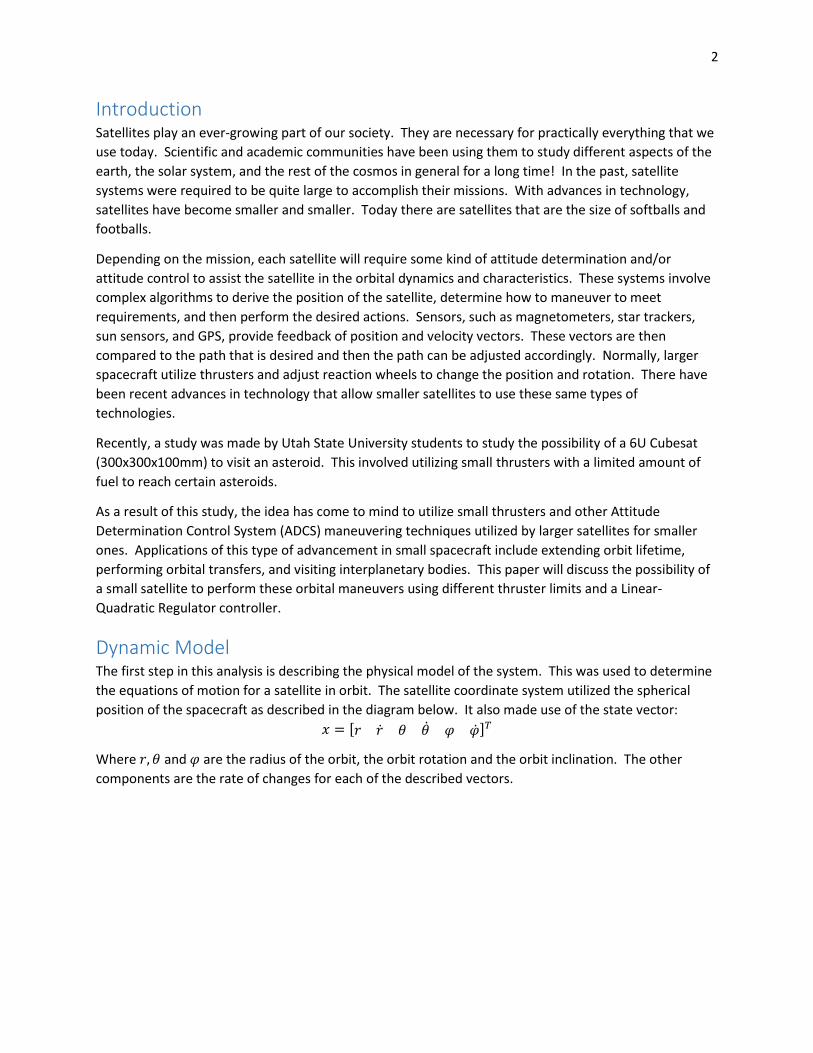
Introduction Satellites play an ever-growing part of our society. They are necessary for practically everything that we
use today. Scientific and academic communities have been using them to study different aspects of the
earth, the solar system, and the rest of the cosmos in general for a long time! In the past, satellite
systems were required to be quite large to accomplish their missions. With advances in technology,
satellites have become smaller and smaller. Today there are satellites that are the size of softballs and
footballs.
Depending on the mission, each satellite will require some kind of attitude determination and/or
attitude control to assist the satellite in the orbital dynamics and characteristics. These systems involve
complex algorithms to derive the position of the satellite, determine how to maneuver to meet
requirements, and then perform the desired actions. Sensors, such as magnetometers, star trackers,
sun sensors, and GPS, provide feedback of position and velocity vectors. These vectors are then
compared to the path that is desired and then the path can be adjusted accordingly. Normally, larger
spacecraft utilize thrusters and adjust reaction wheels to change the position and rotation. There have
been recent advances in technology that allow smaller satellites to use these same types of
technologies.
Recently, a study was made by Utah State University students to study the possibility of a 6U Cubesat
(300x300x100mm) to visit an asteroid. This involved utilizing small thrusters with a limited amount of
fuel to reach certain asteroids.
As a result of this study, the idea has come to mind to utilize small thrusters and other Attitude
Determination Control System (ADCS) maneuvering techniques utilized by larger satellites for smaller
ones. Applications of this type of advancement in small spacecraft include extending orbit lifetime,
performing orbital transfers, and visiting interplanetary bodies. This paper will discuss the possibility of
a small satellite to perform these orbital maneuvers using different thruster limits and a Linear-
Quadratic Regulator controller.
Dynamic Model The first step in this analysis is describing the physical model of the system. This was used to determine
the equations of motion for a satellite in orbit. The satellite coordinate system utilized the spherical
position of the spacecraft as described in the diagram below. It also made use of the state vector:
𝑥 = [𝑟 �̇� 𝜃 �̇� 𝜑 �̇�]𝑇
Where 𝑟, 𝜃 and 𝜑 are the radius of the orbit, the orbit rotation and the orbit inclination. The other
components are the rate of changes for each of the described vectors.

3
The dynamic equations of motion for movement of the satellite in the inertial frame are
�̇�(𝑡) = ℎ(𝑥, 𝑢) =
[
�̇�
𝑟�̇�2 cos2 𝜑 + 𝑟�̇�2 −𝜇
𝑟2+ 𝑢𝑟
1
𝑚�̇�
−2�̇��̇�
𝑟+
2�̇��̇� sin𝜑
cos𝜑+ 𝑢𝜃
1
𝑚𝑟 cos𝜑�̇�
−�̇�2 cos𝜑 sin𝜑 −2�̇��̇�
𝑟+ 𝑢𝜑
1
𝑚𝑟 ]
where 𝜇 is the gravitational constant 𝐺𝑀𝑒𝑎𝑟𝑡ℎ, m is the mass of the spacecraft, and 𝑢𝑟, 𝑢𝜃 and 𝑢𝜑 are
the available thrust in along a specific vector (radius, rotation and inclination respectively). These state
equations define the rates of change in positions and velocities as defined by Dr. Chen in his book. [1]
Figure 1 - Satellite Coordinate System
As this system is nonlinear, the system needed to be linearized as to obtain an optimized controller.
One method that was used to linearize the system was to define a circular orbit with the initial
conditions of a set radius 𝑟0 and a rotation about the equator 𝑤0 (also represented as �̇�0). The initial
state vector 𝑥0(𝑡) was then referenced as
𝑥0(𝑡) = [𝑟0 0 𝑤0𝑡 𝑤0 0 0]𝑇
This was then placed into the function �̇�(𝑡) from above. From this, the values for the state space
equation
�̇̅�(𝑡) = �̅��̅� + �̅��̅� which resulted in the following matrices for �̅� and �̅�
�̅� =
[ 03𝑤0
2
0000
100
−2𝑤0
𝑟000
000000
02𝑤0𝑟0
1000
00000
−𝑤02
000010]
�̅� =
[
0 0 01
𝑚0 0
0 0 0
01
𝑚𝑟00
0 0 0
0 01
𝑚𝑟0]
where �̅� = 𝑥 and �̅� = [𝑢𝑟 𝑢𝜃 𝑢𝜑]𝑇.

4
Closed-Loop Control The linearized state space model given above remains in a stable orbit unless acted upon by additional
forces. These forces, which are placed into the u input variable, can be classified as disturbances to the
orbit. These include thrust in each of the directions, drag, solar pressure, etc. The main input force is
thrust. This defines the control loop system in the following diagram
Figure 2 - Control Loop
For controller purposes, the disturbance forces are canceled out and only the desired path determines
the controller gains. With the model from the linearized system and the exact system, �̅� can be defined
as the deviation of the state vector 𝑥𝑟 as �̅� = 𝑥 − 𝑥𝑟.
This results in the error equation given above as �̇̅�. It is desired to control the system using full state
feedback where �̅� = −𝐾�̅�. The goal is to design a LQR controller for the satellite in orbit. The LQR
controller solves for the optimal state feedback matrix K that minimizes the following equation
𝐽 = ∫(𝑥𝑇𝑄𝑥 + 𝑢𝑇𝑅𝑢)𝑑𝑡
∞
0
where Q and R are symmetrical weighting matrices. The gains were selected using Bryson’s rule as
described in the Linear Controls class. This is used to create a system to produce ideal input given ideal
circumstances. These values can be seen in the files used in Matlab simulations.
Propulsion Technologies As there are different technologies available to spacecraft for propulsion uses, this section describes in
brief detail some of the systems that were used in tests.
There are countless possibilities for propulsion techniques, however, not all of them are ideal for the use
in small satellites such as CubeSats. This can be due to the size of the system, the power requirements
or the mass. Also, some systems are too overpowered for such a small mass.
The systems that were used in this study were as follows: an ideal thruster (minimal mass, no size
requirements and unlimited thrust), a Magnetoplasmadynamic Thruster (MPD, ~100 N of thrust, but are
still quite large and massive), an Electrostatic Ion Thruster (0.01-5 N of thrust and have minimal mass
requirements), and a Micro-Pulse Plasma Thruster (μPPT, 0.05-0.1 N of thrust and have minimal mass
and size requirements). For each of the tests described in the following sections, the saturation levels
placed on the thrusters were as follows:
5
Thruster Type Maximum Thrust (N)
Ideal ∞
MPD 100
Ion Thruster 5
μPPT 0.1
Implementation and Results With the model in place, several paths were designed to meet certain criteria. The following tests were
created to implement the controller design and identify performance characteristics: 1) A circular orbit
transfer from one altitude, inclination and orbit position, 2) The effect of drag on a satellite orbit, 3) The
same as test 1, but introducing drag as a disturbance force, and 4) Extending satellite orbit to highly
elliptical orbits for asteroid interception. These tests will be described below along with their respective
results. Each test includes data from each of the thrusters described above.
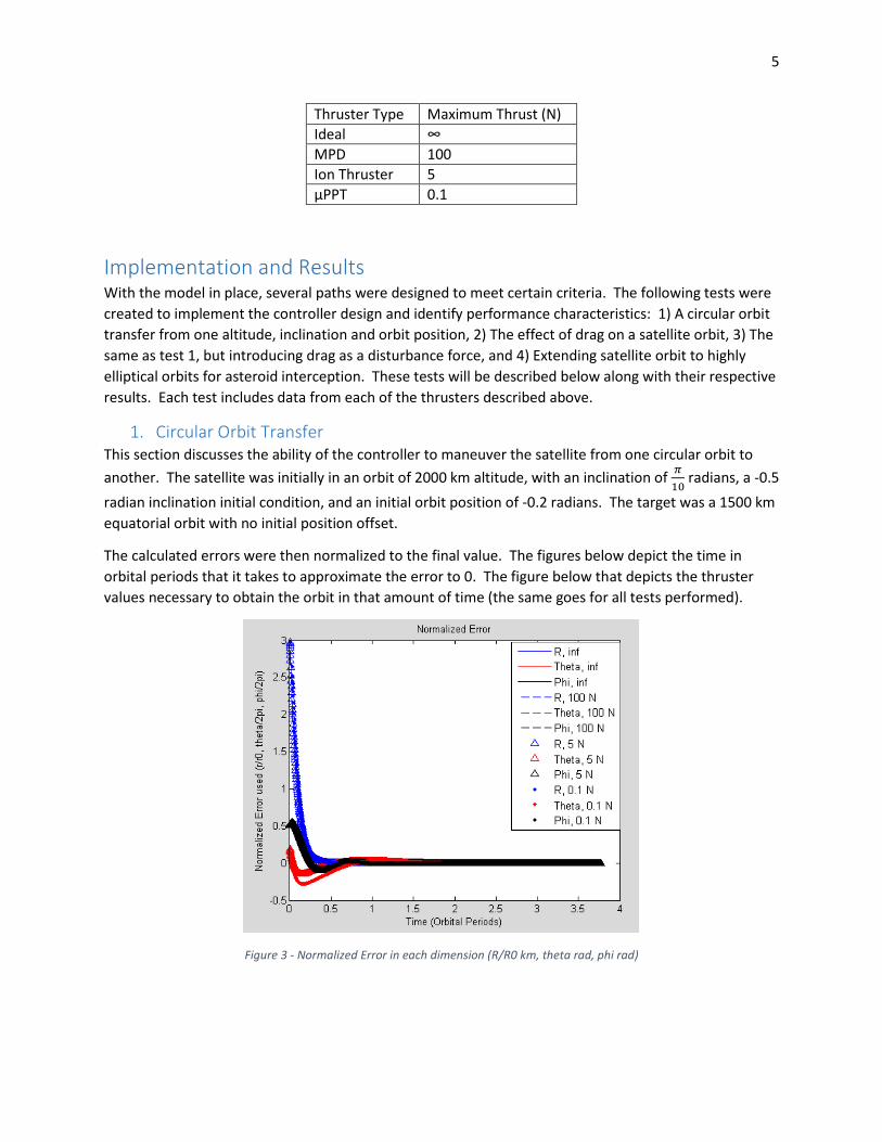
1. Circular Orbit Transfer This section discusses the ability of the controller to maneuver the satellite from one circular orbit to
another. The satellite was initially in an orbit of 2000 km altitude, with an inclination of 𝜋
10 radians, a -0.5
radian inclination initial condition, and an initial orbit position of -0.2 radians. The target was a 1500 km
equatorial orbit with no initial position offset.
The calculated errors were then normalized to the final value. The figures below depict the time in
orbital periods that it takes to approximate the error to 0. The figure below that depicts the thruster
values necessary to obtain the orbit in that amount of time (the same goes for all tests performed).
Figure 3 - Normalized Error in each dimension (R/R0 km, theta rad, phi rad)

6
Figure 4 - Thrust used, Test 1
Figures 3 and 4 depict the amount of error over several orbit periods and the amount of thrust utilized
by the spacecraft. As can be seen, the error in all three categories reduces to a small percentage in
approximately 1 orbit for all cases. The interesting details are however listed in the thrust page. Due to
the high initial error, the spacecraft thrusters fire to adjust for the discrepancies, most notably in the r
direction. The values for r thrust are quite large, but only fire for brief periods of time. The thruster
type that has the most difficulty attaining the steady state value (𝑢𝑖 = 0) is the μPPT thruster. Due to
the small available thrust, it has difficulty reaching the desired value for a little bit longer (as noted by
the lower red line in figure 3).
2. Atmospheric Drag This section discusses the effects that atmospheric drag have on the satellite placed in a circular orbit.
Due to the atmospheric changes over the course of the solar cycle, a specific date was placed in the
NASA MSIS model to collect the atmospheric density from a range of 0 to 1000 km in altitude (after
1000 km, atmospheric drag has little effect). The satellite was placed in orbits of 1000, 750, 500 and 250
km in altitude in an equatorial circular orbit with no initial position offsets.
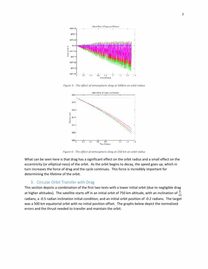
The figure below depicts the effects of drag at the given altitudes. The MSIS drag data was used to
calculate the force of drag during high, average and low solar activity for the given day. The plots depict
the drag during each of those times with high solar activity shown in green, average activity shown in
red and low activity shown in magenta. As a result of this study, it was found that drag has very little
effect at and above altitudes of 750 km, therefore the plots for 500 km altitude and 250 km altitude are
shown below.
7
Figure 5 - The effect of atmospheric drag at 500km on orbit radius
Figure 6 - The effect of atmospheric drag at 250 km on orbit radius
What can be seen here is that drag has a significant effect on the orbit radius and a small effect on the
eccentricity (or elliptical-ness) of the orbit. As the orbit begins to decay, the speed goes up, which in
turn increases the force of drag and the cycle continues. This force is incredibly important for
determining the lifetime of the orbit.
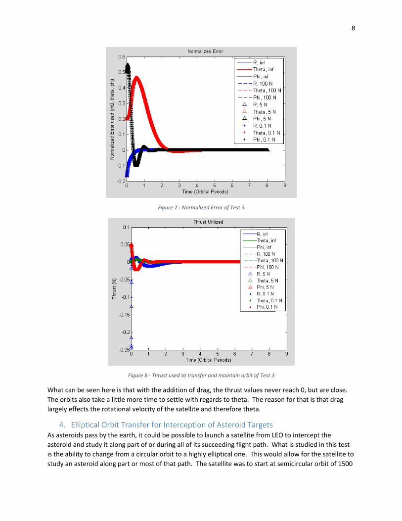
3. Circular Orbit Transfer with Drag This section depicts a combination of the first two tests with a lower initial orbit (due to negligible drag
at higher altitudes). The satellite starts off in an initial orbit of 750 km altitude, with an inclination of 𝜋
10
radians, a -0.5 radian inclination initial condition, and an initial orbit position of -0.2 radians. The target
was a 500 km equatorial orbit with no initial position offset. The graphs below depict the normalized
errors and the thrust needed to transfer and maintain the orbit.
8
Figure 7 - Normalized Error of Test 3
Figure 8 - Thrust used to transfer and maintain orbit of Test 3
What can be seen here is that with the addition of drag, the thrust values never reach 0, but are close.
The orbits also take a little more time to settle with regards to theta. The reason for that is that drag
largely effects the rotational velocity of the satellite and therefore theta.
4. Elliptical Orbit Transfer for Interception of Asteroid Targets As asteroids pass by the earth, it could be possible to launch a satellite from LEO to intercept the
asteroid and study it along part of or during all of its succeeding flight path. What is studied in this test
is the ability to change from a circular orbit to a highly elliptical one. This would allow for the satellite to
study an asteroid along part or most of that path. The satellite was to start at semicircular orbit of 1500
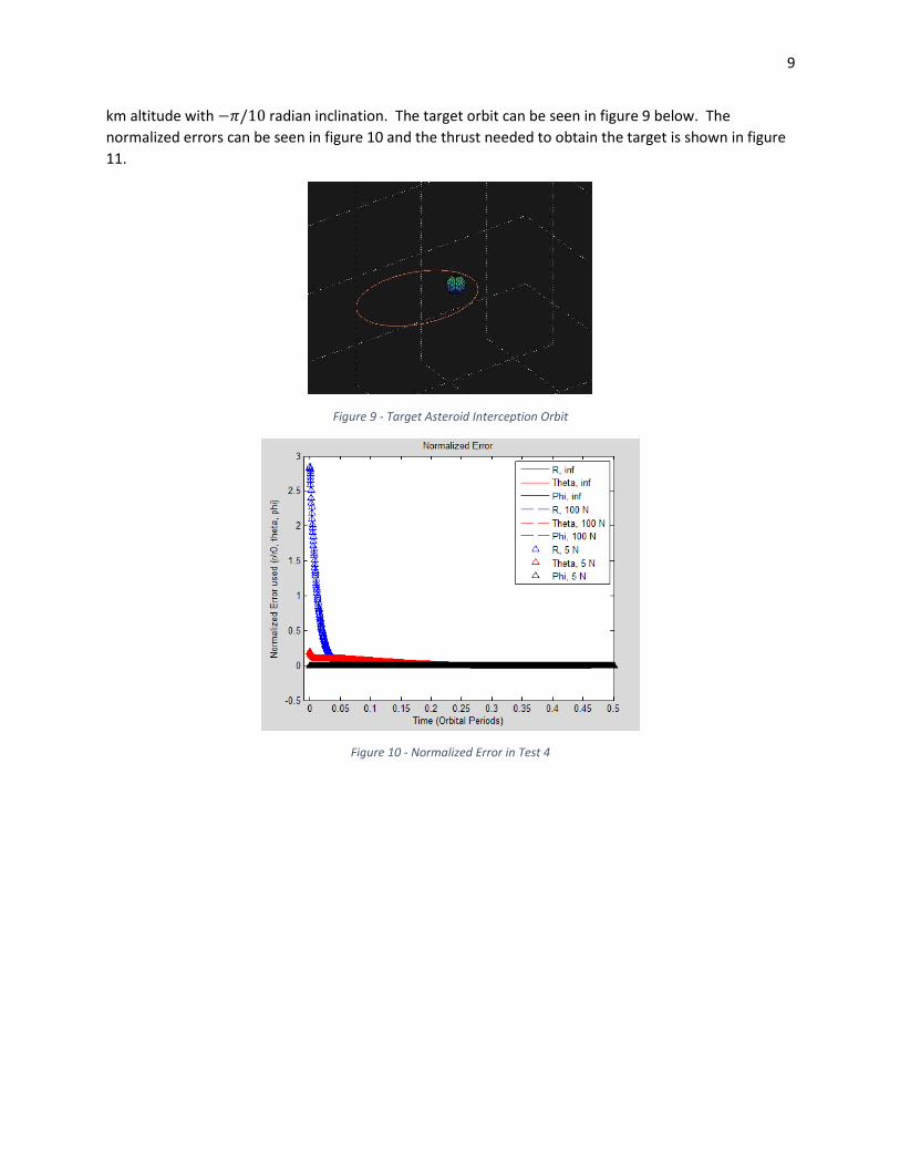
9
km altitude with −𝜋/10 radian inclination. The target orbit can be seen in figure 9 below. The
normalized errors can be seen in figure 10 and the thrust needed to obtain the target is shown in figure
11.
Figure 9 - Target Asteroid Interception Orbit
Figure 10 - Normalized Error in Test 4

10
Figure 11 - Thrust used to transfer and maintain asteroid interception orbit
The data above depicts that it is possible to intercept an asteroid with this given trajectory. However,
there are only 3 of the 4 thrusters that are able to do so (The μPPT could not). All thrusters might be
able to do so with careful path planning and thruster use. This is one area that could be developed
further in the future.
Conclusion The results of this test prove that a single LQR controller is capable of performing the necessary control
commands to make orbital maneuvers to extend orbit lifetime, change orbit path and possibly intercept
interplanetary targets. Future work will be needed to determine other disturbance sources, adjust for
nonlinearities in solar activity, and account for multiple body dynamics (such as an Earth-moon model or
Earth-sun, etc.). However, it is safe to say that with the advances in current technologies for CubeSat
propulsion, new missions will be undertaken to pursue scientific and scholastic goals.

11
References [1] Swenson, Charles. "Meeting with Dr. Charles Swenson." Personal interview. Nov. 2014.
[2] Sharma. "Linear Control Systems." Utah State University. 2014. Lecture.
[3] Center for Space Engineering USU, “RUNNER: ECE 5240 Space Systems Design Project,”
2014. Available by request to Dr. Charles Swenson, PhD, USU
[4] "Orbital Mechanics." Wikipedia. Wikimedia Foundation, 12 Mar. 2014. Web. 09 Dec. 2014.