option 300 user's and programming guide, e44xxb esg …nagui/labequip/synth/manuals/e... ·...
TRANSCRIPT

Serial Number Prefixes:
User’s and Programming Guide
Agilent Technologies
ESG Family Signal Generators
Option 300 Base Station BERT
Part No. E4400-90305
Printed in USA
April 2002
Supersedes: June 2001
© Copyright 1999–2002 Agilent Technologies, Inc.
(Affix Label Here)

ii
Contents
iii
1. Getting StartedProduct Overview . . . . . . . . . . . . . . . . . . . . . . . . . . . . . . . . . . . . . . . . . . . . . . . . . . . . . . . . . . . .1-2
GSM . . . . . . . . . . . . . . . . . . . . . . . . . . . . . . . . . . . . . . . . . . . . . . . . . . . . . . . . . . . . . . . . . . . . .1-2EDGE. . . . . . . . . . . . . . . . . . . . . . . . . . . . . . . . . . . . . . . . . . . . . . . . . . . . . . . . . . . . . . . . . . . .1-2Baseband BER Tester . . . . . . . . . . . . . . . . . . . . . . . . . . . . . . . . . . . . . . . . . . . . . . . . . . . . . . .1-2
2. Making MeasurementsMeasuring RF Loopback BER . . . . . . . . . . . . . . . . . . . . . . . . . . . . . . . . . . . . . . . . . . . . . . . . . .2-2
Required Equipment. . . . . . . . . . . . . . . . . . . . . . . . . . . . . . . . . . . . . . . . . . . . . . . . . . . . . . . .2-2Connecting the Test Equipment. . . . . . . . . . . . . . . . . . . . . . . . . . . . . . . . . . . . . . . . . . . . . . .2-3Configuring GSM Mode on the Agilent Technologies E4406A VSA Series Transmitter Tester . . . . . . . . . . . . . . . . . . . . . . . . . . . . . . . . . . . . . . . .2-3Configuring GSM Mode on the ESG-D Series Signal Generator . . . . . . . . . . . . . . . . . . . . .2-4Synchronizing to the BCH . . . . . . . . . . . . . . . . . . . . . . . . . . . . . . . . . . . . . . . . . . . . . . . . . . .2-7Synchronizing to the TCH . . . . . . . . . . . . . . . . . . . . . . . . . . . . . . . . . . . . . . . . . . . . . . . . . . .2-8Making Loopback BER Measurements . . . . . . . . . . . . . . . . . . . . . . . . . . . . . . . . . . . . . . . . .2-9Using Amplitude Sensitivity Search . . . . . . . . . . . . . . . . . . . . . . . . . . . . . . . . . . . . . . . . . .2-11
Using the External Frame Trigger Function with the EDGE Format . . . . . . . . . . . . . . . . .2-13Measuring the Initial Delay Value. . . . . . . . . . . . . . . . . . . . . . . . . . . . . . . . . . . . . . . . . . . .2-13Adjusting the Delay Value . . . . . . . . . . . . . . . . . . . . . . . . . . . . . . . . . . . . . . . . . . . . . . . . . .2-14
3. Softkey ReferenceGSM/EDGE Base Station Test Softkeys . . . . . . . . . . . . . . . . . . . . . . . . . . . . . . . . . . . . . . . . . .3-2
Mode. . . . . . . . . . . . . . . . . . . . . . . . . . . . . . . . . . . . . . . . . . . . . . . . . . . . . . . . . . . . . . . . . . . . .3-2Adjust Gain . . . . . . . . . . . . . . . . . . . . . . . . . . . . . . . . . . . . . . . . . . . . . . . . . . . . . . . . . . . . . . .3-3Arm Sensitivity Search. . . . . . . . . . . . . . . . . . . . . . . . . . . . . . . . . . . . . . . . . . . . . . . . . . . . . .3-3Baseband BERT . . . . . . . . . . . . . . . . . . . . . . . . . . . . . . . . . . . . . . . . . . . . . . . . . . . . . . . . . . .3-3BER% Uncoded Configure . . . . . . . . . . . . . . . . . . . . . . . . . . . . . . . . . . . . . . . . . . . . . . . . . . .3-3BER Mode Off On . . . . . . . . . . . . . . . . . . . . . . . . . . . . . . . . . . . . . . . . . . . . . . . . . . . . . . . . . .3-4BERT . . . . . . . . . . . . . . . . . . . . . . . . . . . . . . . . . . . . . . . . . . . . . . . . . . . . . . . . . . . . . . . . . . . .3-4BERT Off On . . . . . . . . . . . . . . . . . . . . . . . . . . . . . . . . . . . . . . . . . . . . . . . . . . . . . . . . . . . . . .3-4BERT Resync Off On. . . . . . . . . . . . . . . . . . . . . . . . . . . . . . . . . . . . . . . . . . . . . . . . . . . . . . . .3-4BERT Trigger . . . . . . . . . . . . . . . . . . . . . . . . . . . . . . . . . . . . . . . . . . . . . . . . . . . . . . . . . . . . .3-4BERT Trigger Source . . . . . . . . . . . . . . . . . . . . . . . . . . . . . . . . . . . . . . . . . . . . . . . . . . . . . . .3-5Bit Count . . . . . . . . . . . . . . . . . . . . . . . . . . . . . . . . . . . . . . . . . . . . . . . . . . . . . . . . . . . . . . . .3-5Bit Delay Off On . . . . . . . . . . . . . . . . . . . . . . . . . . . . . . . . . . . . . . . . . . . . . . . . . . . . . . . . . . .3-5BLER% MCS5 Configure . . . . . . . . . . . . . . . . . . . . . . . . . . . . . . . . . . . . . . . . . . . . . . . . . . . .3-5BLER% MCS9 Configure . . . . . . . . . . . . . . . . . . . . . . . . . . . . . . . . . . . . . . . . . . . . . . . . . . . .3-6BLER% Configure . . . . . . . . . . . . . . . . . . . . . . . . . . . . . . . . . . . . . . . . . . . . . . . . . . . . . . . . . .3-6Block Count . . . . . . . . . . . . . . . . . . . . . . . . . . . . . . . . . . . . . . . . . . . . . . . . . . . . . . . . . . . . . .3-6Block Erasure . . . . . . . . . . . . . . . . . . . . . . . . . . . . . . . . . . . . . . . . . . . . . . . . . . . . . . . . . . . . .3-6BTS BERT EDGE Loopback. . . . . . . . . . . . . . . . . . . . . . . . . . . . . . . . . . . . . . . . . . . . . . . . . .3-7BTS BERT GSM Loopback . . . . . . . . . . . . . . . . . . . . . . . . . . . . . . . . . . . . . . . . . . . . . . . . . . .3-7Bus . . . . . . . . . . . . . . . . . . . . . . . . . . . . . . . . . . . . . . . . . . . . . . . . . . . . . . . . . . . . . . . . . . . . . .3-7Channel Band . . . . . . . . . . . . . . . . . . . . . . . . . . . . . . . . . . . . . . . . . . . . . . . . . . . . . . . . . . . . .3-7Channel Number. . . . . . . . . . . . . . . . . . . . . . . . . . . . . . . . . . . . . . . . . . . . . . . . . . . . . . . . . . .3-8Class Ib Bit Error . . . . . . . . . . . . . . . . . . . . . . . . . . . . . . . . . . . . . . . . . . . . . . . . . . . . . . . . . .3-8Class Ib RBER. . . . . . . . . . . . . . . . . . . . . . . . . . . . . . . . . . . . . . . . . . . . . . . . . . . . . . . . . . . . .3-8Class II Bit Error . . . . . . . . . . . . . . . . . . . . . . . . . . . . . . . . . . . . . . . . . . . . . . . . . . . . . . . . . .3-9Class II RBER . . . . . . . . . . . . . . . . . . . . . . . . . . . . . . . . . . . . . . . . . . . . . . . . . . . . . . . . . . . . .3-9
iv
Contents
Clock Gate Off On . . . . . . . . . . . . . . . . . . . . . . . . . . . . . . . . . . . . . . . . . . . . . . . . . . . . . . . . . 3-9Clock Gate Polarity Neg Pos . . . . . . . . . . . . . . . . . . . . . . . . . . . . . . . . . . . . . . . . . . . . . . . . . 3-9Clock Polarity Neg Pos . . . . . . . . . . . . . . . . . . . . . . . . . . . . . . . . . . . . . . . . . . . . . . . . . . . . . 3-10 Configure BER% . . . . . . . . . . . . . . . . . . . . . . . . . . . . . . . . . . . . . . . . . . . . . . . . . . . . . . . . . 3-10Configure BERT . . . . . . . . . . . . . . . . . . . . . . . . . . . . . . . . . . . . . . . . . . . . . . . . . . . . . . . . . . 3-10Configure Measurement . . . . . . . . . . . . . . . . . . . . . . . . . . . . . . . . . . . . . . . . . . . . . . . . . . . 3-10Configure Sensitivity Search . . . . . . . . . . . . . . . . . . . . . . . . . . . . . . . . . . . . . . . . . . . . . . . . 3-10Configure Triggers . . . . . . . . . . . . . . . . . . . . . . . . . . . . . . . . . . . . . . . . . . . . . . . . . . . . . . . . 3-11Cycle Count. . . . . . . . . . . . . . . . . . . . . . . . . . . . . . . . . . . . . . . . . . . . . . . . . . . . . . . . . . . . . . 3-11Cycle End . . . . . . . . . . . . . . . . . . . . . . . . . . . . . . . . . . . . . . . . . . . . . . . . . . . . . . . . . . . . . . . 3-11Data. . . . . . . . . . . . . . . . . . . . . . . . . . . . . . . . . . . . . . . . . . . . . . . . . . . . . . . . . . . . . . . . . . . . 3-11Data Polarity Neg Pos . . . . . . . . . . . . . . . . . . . . . . . . . . . . . . . . . . . . . . . . . . . . . . . . . . . . . 3-12Delayed Bits . . . . . . . . . . . . . . . . . . . . . . . . . . . . . . . . . . . . . . . . . . . . . . . . . . . . . . . . . . . . . 3-12Display BER % Exp . . . . . . . . . . . . . . . . . . . . . . . . . . . . . . . . . . . . . . . . . . . . . . . . . . . . . . . 3-12Display Update Cycle End Cont . . . . . . . . . . . . . . . . . . . . . . . . . . . . . . . . . . . . . . . . . . . . . 3-12Downlink MCS-1 . . . . . . . . . . . . . . . . . . . . . . . . . . . . . . . . . . . . . . . . . . . . . . . . . . . . . . . . . 3-13Downlink MCS-5 . . . . . . . . . . . . . . . . . . . . . . . . . . . . . . . . . . . . . . . . . . . . . . . . . . . . . . . . . 3-13Downlink MCS-9 . . . . . . . . . . . . . . . . . . . . . . . . . . . . . . . . . . . . . . . . . . . . . . . . . . . . . . . . . 3-13EDGE BERT Off On. . . . . . . . . . . . . . . . . . . . . . . . . . . . . . . . . . . . . . . . . . . . . . . . . . . . . . . 3-13Error Count . . . . . . . . . . . . . . . . . . . . . . . . . . . . . . . . . . . . . . . . . . . . . . . . . . . . . . . . . . . . . 3-14Error Rate . . . . . . . . . . . . . . . . . . . . . . . . . . . . . . . . . . . . . . . . . . . . . . . . . . . . . . . . . . . . . . 3-14E-TCH/F43.2. . . . . . . . . . . . . . . . . . . . . . . . . . . . . . . . . . . . . . . . . . . . . . . . . . . . . . . . . . . . . 3-14Exceeds Any Limits . . . . . . . . . . . . . . . . . . . . . . . . . . . . . . . . . . . . . . . . . . . . . . . . . . . . . . . 3-14Exceeds Any Threshold . . . . . . . . . . . . . . . . . . . . . . . . . . . . . . . . . . . . . . . . . . . . . . . . . . . . 3-15Ext . . . . . . . . . . . . . . . . . . . . . . . . . . . . . . . . . . . . . . . . . . . . . . . . . . . . . . . . . . . . . . . . . . . . . 3-15Ext Frame Trigger Delay . . . . . . . . . . . . . . . . . . . . . . . . . . . . . . . . . . . . . . . . . . . . . . . . . . 3-15Ext Frame Trigger Polarity Neg Pos . . . . . . . . . . . . . . . . . . . . . . . . . . . . . . . . . . . . . . . . . . 3-15Fail Hold . . . . . . . . . . . . . . . . . . . . . . . . . . . . . . . . . . . . . . . . . . . . . . . . . . . . . . . . . . . . . . . . 3-15Frame Count . . . . . . . . . . . . . . . . . . . . . . . . . . . . . . . . . . . . . . . . . . . . . . . . . . . . . . . . . . . . 3-16Frame Erasure . . . . . . . . . . . . . . . . . . . . . . . . . . . . . . . . . . . . . . . . . . . . . . . . . . . . . . . . . . . 3-16Frame Erasure Ratio . . . . . . . . . . . . . . . . . . . . . . . . . . . . . . . . . . . . . . . . . . . . . . . . . . . . . . 3-17Frame Repeat Single Cont. . . . . . . . . . . . . . . . . . . . . . . . . . . . . . . . . . . . . . . . . . . . . . . . . . 3-17Frame Trigger Source BCH PDCH . . . . . . . . . . . . . . . . . . . . . . . . . . . . . . . . . . . . . . . . . . . 3-18Frame Trigger Source Int Ext . . . . . . . . . . . . . . . . . . . . . . . . . . . . . . . . . . . . . . . . . . . . . . . 3-18Freq Channels . . . . . . . . . . . . . . . . . . . . . . . . . . . . . . . . . . . . . . . . . . . . . . . . . . . . . . . . . . . 3-19Freq Channels Off On . . . . . . . . . . . . . . . . . . . . . . . . . . . . . . . . . . . . . . . . . . . . . . . . . . . . . 3-19GSM 450 Base . . . . . . . . . . . . . . . . . . . . . . . . . . . . . . . . . . . . . . . . . . . . . . . . . . . . . . . . . . . 3-19GSM 450 Mobile . . . . . . . . . . . . . . . . . . . . . . . . . . . . . . . . . . . . . . . . . . . . . . . . . . . . . . . . . . 3-19GSM 450/850 Base . . . . . . . . . . . . . . . . . . . . . . . . . . . . . . . . . . . . . . . . . . . . . . . . . . . . . . . . 3-20GSM 450/850 Mobile . . . . . . . . . . . . . . . . . . . . . . . . . . . . . . . . . . . . . . . . . . . . . . . . . . . . . . 3-20GSM 480 Mobile . . . . . . . . . . . . . . . . . . . . . . . . . . . . . . . . . . . . . . . . . . . . . . . . . . . . . . . . . . 3-20GSM 850 Base . . . . . . . . . . . . . . . . . . . . . . . . . . . . . . . . . . . . . . . . . . . . . . . . . . . . . . . . . . . 3-20GSM 850 Mobile . . . . . . . . . . . . . . . . . . . . . . . . . . . . . . . . . . . . . . . . . . . . . . . . . . . . . . . . . . 3-21GSM BERT Off On . . . . . . . . . . . . . . . . . . . . . . . . . . . . . . . . . . . . . . . . . . . . . . . . . . . . . . . . 3-21High Amplitude . . . . . . . . . . . . . . . . . . . . . . . . . . . . . . . . . . . . . . . . . . . . . . . . . . . . . . . . . . 3-21Immediate. . . . . . . . . . . . . . . . . . . . . . . . . . . . . . . . . . . . . . . . . . . . . . . . . . . . . . . . . . . . . . . 3-22Impedance 75 Ohm TTL . . . . . . . . . . . . . . . . . . . . . . . . . . . . . . . . . . . . . . . . . . . . . . . . . . . 3-22Initial Bit Count . . . . . . . . . . . . . . . . . . . . . . . . . . . . . . . . . . . . . . . . . . . . . . . . . . . . . . . . . . 3-22Initial Block Count . . . . . . . . . . . . . . . . . . . . . . . . . . . . . . . . . . . . . . . . . . . . . . . . . . . . . . . . 3-22
Contents
v
Low Amplitude . . . . . . . . . . . . . . . . . . . . . . . . . . . . . . . . . . . . . . . . . . . . . . . . . . . . . . . . . . .3-23Max. Data Rate 2Mbps 10Mbps . . . . . . . . . . . . . . . . . . . . . . . . . . . . . . . . . . . . . . . . . . . . . .3-23Measurement Mode BER% Search . . . . . . . . . . . . . . . . . . . . . . . . . . . . . . . . . . . . . . . . . . .3-23Measurement Mode BLER% Search . . . . . . . . . . . . . . . . . . . . . . . . . . . . . . . . . . . . . . . . . .3-23Multiframe Channel . . . . . . . . . . . . . . . . . . . . . . . . . . . . . . . . . . . . . . . . . . . . . . . . . . . . . . .3-24No Limits . . . . . . . . . . . . . . . . . . . . . . . . . . . . . . . . . . . . . . . . . . . . . . . . . . . . . . . . . . . . . . . .3-24No Thresholds . . . . . . . . . . . . . . . . . . . . . . . . . . . . . . . . . . . . . . . . . . . . . . . . . . . . . . . . . . . .3-24Pass Amplitude . . . . . . . . . . . . . . . . . . . . . . . . . . . . . . . . . . . . . . . . . . . . . . . . . . . . . . . . . . .3-25PN9 . . . . . . . . . . . . . . . . . . . . . . . . . . . . . . . . . . . . . . . . . . . . . . . . . . . . . . . . . . . . . . . . . . . .3-25PN15 . . . . . . . . . . . . . . . . . . . . . . . . . . . . . . . . . . . . . . . . . . . . . . . . . . . . . . . . . . . . . . . . . . .3-25Pass Amplitude . . . . . . . . . . . . . . . . . . . . . . . . . . . . . . . . . . . . . . . . . . . . . . . . . . . . . . . . . .3-26Pass/Fail Limits. . . . . . . . . . . . . . . . . . . . . . . . . . . . . . . . . . . . . . . . . . . . . . . . . . . . . . . . . . .3-26Pass/Fail Off On . . . . . . . . . . . . . . . . . . . . . . . . . . . . . . . . . . . . . . . . . . . . . . . . . . . . . . . . . .3-26Pass/Fail Update . . . . . . . . . . . . . . . . . . . . . . . . . . . . . . . . . . . . . . . . . . . . . . . . . . . . . . . . . .3-27Restore EDGE Factory Default . . . . . . . . . . . . . . . . . . . . . . . . . . . . . . . . . . . . . . . . . . . . . .3-27Restore GSM Factory Default. . . . . . . . . . . . . . . . . . . . . . . . . . . . . . . . . . . . . . . . . . . . . . . .3-27Resync Limits . . . . . . . . . . . . . . . . . . . . . . . . . . . . . . . . . . . . . . . . . . . . . . . . . . . . . . . . . . . .3-27Search DL MCS5 Configure . . . . . . . . . . . . . . . . . . . . . . . . . . . . . . . . . . . . . . . . . . . . . . . . .3-28Search DL MCS9 Configure . . . . . . . . . . . . . . . . . . . . . . . . . . . . . . . . . . . . . . . . . . . . . . . . .3-28Search Uncoded Configure . . . . . . . . . . . . . . . . . . . . . . . . . . . . . . . . . . . . . . . . . . . . . . . . . .3-28Sensitivity Search Configure . . . . . . . . . . . . . . . . . . . . . . . . . . . . . . . . . . . . . . . . . . . . . . . .3-28Special Pattern 0’s 1’s . . . . . . . . . . . . . . . . . . . . . . . . . . . . . . . . . . . . . . . . . . . . . . . . . . . . . .3-28Special Pattern Ignore Off On . . . . . . . . . . . . . . . . . . . . . . . . . . . . . . . . . . . . . . . . . . . . . . .3-29Spectrum Invert Off On . . . . . . . . . . . . . . . . . . . . . . . . . . . . . . . . . . . . . . . . . . . . . . . . . . . .3-29Stop Measurement . . . . . . . . . . . . . . . . . . . . . . . . . . . . . . . . . . . . . . . . . . . . . . . . . . . . . . . .3-29Stop Sensitivity Search. . . . . . . . . . . . . . . . . . . . . . . . . . . . . . . . . . . . . . . . . . . . . . . . . . . . .3-29Sync Source BCH TCH . . . . . . . . . . . . . . . . . . . . . . . . . . . . . . . . . . . . . . . . . . . . . . . . . . . . .3-30Synchronize to BCH/TCH. . . . . . . . . . . . . . . . . . . . . . . . . . . . . . . . . . . . . . . . . . . . . . . . . . .3-30Synchronize to BCH/PDCH . . . . . . . . . . . . . . . . . . . . . . . . . . . . . . . . . . . . . . . . . . . . . . . . .3-30Target% . . . . . . . . . . . . . . . . . . . . . . . . . . . . . . . . . . . . . . . . . . . . . . . . . . . . . . . . . . . . . . . . .3-30Target BER % . . . . . . . . . . . . . . . . . . . . . . . . . . . . . . . . . . . . . . . . . . . . . . . . . . . . . . . . . . . .3-31Target BLER % . . . . . . . . . . . . . . . . . . . . . . . . . . . . . . . . . . . . . . . . . . . . . . . . . . . . . . . . . . .3-31TCH/FS . . . . . . . . . . . . . . . . . . . . . . . . . . . . . . . . . . . . . . . . . . . . . . . . . . . . . . . . . . . . . . . . .3-31Threshold # of Events to Stop. . . . . . . . . . . . . . . . . . . . . . . . . . . . . . . . . . . . . . . . . . . . . . . .3-31Total Bits . . . . . . . . . . . . . . . . . . . . . . . . . . . . . . . . . . . . . . . . . . . . . . . . . . . . . . . . . . . . . . . .3-32Timeslot # . . . . . . . . . . . . . . . . . . . . . . . . . . . . . . . . . . . . . . . . . . . . . . . . . . . . . . . . . . . . . . .3-32Transmit Settings . . . . . . . . . . . . . . . . . . . . . . . . . . . . . . . . . . . . . . . . . . . . . . . . . . . . . . . . .3-32Trigger Key . . . . . . . . . . . . . . . . . . . . . . . . . . . . . . . . . . . . . . . . . . . . . . . . . . . . . . . . . . . . . .3-32Uncoded . . . . . . . . . . . . . . . . . . . . . . . . . . . . . . . . . . . . . . . . . . . . . . . . . . . . . . . . . . . . . . . . .3-33Uplink MCS-1 . . . . . . . . . . . . . . . . . . . . . . . . . . . . . . . . . . . . . . . . . . . . . . . . . . . . . . . . . . . .3-33Uplink MCS-5 . . . . . . . . . . . . . . . . . . . . . . . . . . . . . . . . . . . . . . . . . . . . . . . . . . . . . . . . . . . .3-33Uplink MCS-9 . . . . . . . . . . . . . . . . . . . . . . . . . . . . . . . . . . . . . . . . . . . . . . . . . . . . . . . . . . . .3-33Uplink Timing Advance . . . . . . . . . . . . . . . . . . . . . . . . . . . . . . . . . . . . . . . . . . . . . . . . . . . .3-34
Display Annotation . . . . . . . . . . . . . . . . . . . . . . . . . . . . . . . . . . . . . . . . . . . . . . . . . . . . . . . . .3-351. Setting Information. . . . . . . . . . . . . . . . . . . . . . . . . . . . . . . . . . . . . . . . . . . . . . . . . . . . . .3-352. Measurement Results . . . . . . . . . . . . . . . . . . . . . . . . . . . . . . . . . . . . . . . . . . . . . . . . . . . .3-373. Other Information. . . . . . . . . . . . . . . . . . . . . . . . . . . . . . . . . . . . . . . . . . . . . . . . . . . . . . .3-37
Rear Panel Overview . . . . . . . . . . . . . . . . . . . . . . . . . . . . . . . . . . . . . . . . . . . . . . . . . . . . . . . .3-381. BER DATA IN Connector . . . . . . . . . . . . . . . . . . . . . . . . . . . . . . . . . . . . . . . . . . . . . . . . .3-38
vi
Contents
2. BER CLK IN Connector . . . . . . . . . . . . . . . . . . . . . . . . . . . . . . . . . . . . . . . . . . . . . . . . . . 3-383. BER GATE IN Connector . . . . . . . . . . . . . . . . . . . . . . . . . . . . . . . . . . . . . . . . . . . . . . . . 3-384. BER MEAS END Connector . . . . . . . . . . . . . . . . . . . . . . . . . . . . . . . . . . . . . . . . . . . . . . 3-385. BER TEST OUT Connector . . . . . . . . . . . . . . . . . . . . . . . . . . . . . . . . . . . . . . . . . . . . . . . 3-396. BER ERR OUT Connector . . . . . . . . . . . . . . . . . . . . . . . . . . . . . . . . . . . . . . . . . . . . . . . . 3-397. BER NO DATA Connector . . . . . . . . . . . . . . . . . . . . . . . . . . . . . . . . . . . . . . . . . . . . . . . . 3-398. BER SYNC LOSS Connector . . . . . . . . . . . . . . . . . . . . . . . . . . . . . . . . . . . . . . . . . . . . . . 3-39
4. Remote ProgrammingOption 300 SCPI Command Reference. . . . . . . . . . . . . . . . . . . . . . . . . . . . . . . . . . . . . . . . . . . 4-2
BER Clock Gate Polarity . . . . . . . . . . . . . . . . . . . . . . . . . . . . . . . . . . . . . . . . . . . . . . . . . . . . 4-2BER Clock Gate State . . . . . . . . . . . . . . . . . . . . . . . . . . . . . . . . . . . . . . . . . . . . . . . . . . . . . . 4-2BER Clock Polarity. . . . . . . . . . . . . . . . . . . . . . . . . . . . . . . . . . . . . . . . . . . . . . . . . . . . . . . . . 4-2BER Cycle Count . . . . . . . . . . . . . . . . . . . . . . . . . . . . . . . . . . . . . . . . . . . . . . . . . . . . . . . . . . 4-2BER Data Pattern . . . . . . . . . . . . . . . . . . . . . . . . . . . . . . . . . . . . . . . . . . . . . . . . . . . . . . . . . 4-3BER Data Polarity . . . . . . . . . . . . . . . . . . . . . . . . . . . . . . . . . . . . . . . . . . . . . . . . . . . . . . . . . 4-3BER Display Mode . . . . . . . . . . . . . . . . . . . . . . . . . . . . . . . . . . . . . . . . . . . . . . . . . . . . . . . . . 4-3BER Display Update Mode . . . . . . . . . . . . . . . . . . . . . . . . . . . . . . . . . . . . . . . . . . . . . . . . . . 4-3BER Input Impedance . . . . . . . . . . . . . . . . . . . . . . . . . . . . . . . . . . . . . . . . . . . . . . . . . . . . . . 4-3BER Maximum Data Rate . . . . . . . . . . . . . . . . . . . . . . . . . . . . . . . . . . . . . . . . . . . . . . . . . . . 4-4BER Measurement Result Query . . . . . . . . . . . . . . . . . . . . . . . . . . . . . . . . . . . . . . . . . . . . . 4-4BER Pass/Fail Judgement Mode . . . . . . . . . . . . . . . . . . . . . . . . . . . . . . . . . . . . . . . . . . . . . . 4-5BER Pass/Fail Limits . . . . . . . . . . . . . . . . . . . . . . . . . . . . . . . . . . . . . . . . . . . . . . . . . . . . . . . 4-5BER Pass/Fail State . . . . . . . . . . . . . . . . . . . . . . . . . . . . . . . . . . . . . . . . . . . . . . . . . . . . . . . . 4-5BER Resync Limits . . . . . . . . . . . . . . . . . . . . . . . . . . . . . . . . . . . . . . . . . . . . . . . . . . . . . . . . 4-5BER Resynchronization State . . . . . . . . . . . . . . . . . . . . . . . . . . . . . . . . . . . . . . . . . . . . . . . . 4-6BER Special Pattern Ignore Data . . . . . . . . . . . . . . . . . . . . . . . . . . . . . . . . . . . . . . . . . . . . . 4-6BER Special Pattern Ignore State. . . . . . . . . . . . . . . . . . . . . . . . . . . . . . . . . . . . . . . . . . . . . 4-6BER Total Bits . . . . . . . . . . . . . . . . . . . . . . . . . . . . . . . . . . . . . . . . . . . . . . . . . . . . . . . . . . . . 4-6BER Trigger Bit Delay . . . . . . . . . . . . . . . . . . . . . . . . . . . . . . . . . . . . . . . . . . . . . . . . . . . . . . 4-6BER Trigger Bit Delay State . . . . . . . . . . . . . . . . . . . . . . . . . . . . . . . . . . . . . . . . . . . . . . . . . 4-7BER Trigger Source . . . . . . . . . . . . . . . . . . . . . . . . . . . . . . . . . . . . . . . . . . . . . . . . . . . . . . . . 4-7BERT State. . . . . . . . . . . . . . . . . . . . . . . . . . . . . . . . . . . . . . . . . . . . . . . . . . . . . . . . . . . . . . . 4-7BERT Trigger Source Selection. . . . . . . . . . . . . . . . . . . . . . . . . . . . . . . . . . . . . . . . . . . . . . . 4-7Bit Count. . . . . . . . . . . . . . . . . . . . . . . . . . . . . . . . . . . . . . . . . . . . . . . . . . . . . . . . . . . . . . . . . 4-8BLER Measurement. . . . . . . . . . . . . . . . . . . . . . . . . . . . . . . . . . . . . . . . . . . . . . . . . . . . . . . . 4-8Block Count . . . . . . . . . . . . . . . . . . . . . . . . . . . . . . . . . . . . . . . . . . . . . . . . . . . . . . . . . . . . . . 4-9Class Ib Bits, Number to be Measured . . . . . . . . . . . . . . . . . . . . . . . . . . . . . . . . . . . . . . . . . 4-9Class II Bits, Number to be Measured . . . . . . . . . . . . . . . . . . . . . . . . . . . . . . . . . . . . . . . . . 4-9Data. . . . . . . . . . . . . . . . . . . . . . . . . . . . . . . . . . . . . . . . . . . . . . . . . . . . . . . . . . . . . . . . . . . . . 4-9External Frame Trigger Delay . . . . . . . . . . . . . . . . . . . . . . . . . . . . . . . . . . . . . . . . . . . . . . 4-12External Frame Trigger Polarity. . . . . . . . . . . . . . . . . . . . . . . . . . . . . . . . . . . . . . . . . . . . . 4-12Frame Count (BER %) . . . . . . . . . . . . . . . . . . . . . . . . . . . . . . . . . . . . . . . . . . . . . . . . . . . . . 4-12Frame Trigger Source . . . . . . . . . . . . . . . . . . . . . . . . . . . . . . . . . . . . . . . . . . . . . . . . . . . . . 4-12Frame Synchronization Source . . . . . . . . . . . . . . . . . . . . . . . . . . . . . . . . . . . . . . . . . . . . . . 4-12Loopback Operating State . . . . . . . . . . . . . . . . . . . . . . . . . . . . . . . . . . . . . . . . . . . . . . . . . . 4-13Measurement Mode, Switching . . . . . . . . . . . . . . . . . . . . . . . . . . . . . . . . . . . . . . . . . . . . . . 4-14Measurement Sensitivity. . . . . . . . . . . . . . . . . . . . . . . . . . . . . . . . . . . . . . . . . . . . . . . . . . . 4-14Measurement, Stopping . . . . . . . . . . . . . . . . . . . . . . . . . . . . . . . . . . . . . . . . . . . . . . . . . . . . 4-15
Contents
vii
Pass/Fail Limit, Class Ib RBER . . . . . . . . . . . . . . . . . . . . . . . . . . . . . . . . . . . . . . . . . . . . . .4-16Pass/Fail Limit, Class II RBER . . . . . . . . . . . . . . . . . . . . . . . . . . . . . . . . . . . . . . . . . . . . . .4-16Pass/Fail Limit, Error Rate . . . . . . . . . . . . . . . . . . . . . . . . . . . . . . . . . . . . . . . . . . . . . . . . .4-16Pass/Fail Limit, Frame Erasure Ratio . . . . . . . . . . . . . . . . . . . . . . . . . . . . . . . . . . . . . . . . .4-16Pass/Fail Limit, Selection . . . . . . . . . . . . . . . . . . . . . . . . . . . . . . . . . . . . . . . . . . . . . . . . . . .4-17Sensitivity Search, Bit Count. . . . . . . . . . . . . . . . . . . . . . . . . . . . . . . . . . . . . . . . . . . . . . . .4-18Sensitivity Search, Block Count. . . . . . . . . . . . . . . . . . . . . . . . . . . . . . . . . . . . . . . . . . . . . .4-18Sensitivity Search, Frame Count . . . . . . . . . . . . . . . . . . . . . . . . . . . . . . . . . . . . . . . . . . . . .4-18Sensitivity Search, Initial Bit Count . . . . . . . . . . . . . . . . . . . . . . . . . . . . . . . . . . . . . . . . . .4-18Sensitivity Search, Initial Block Count . . . . . . . . . . . . . . . . . . . . . . . . . . . . . . . . . . . . . . . .4-19Sensitivity Search, Initial Frame Count . . . . . . . . . . . . . . . . . . . . . . . . . . . . . . . . . . . . . . .4-19Sensitivity Search, Target Error Level . . . . . . . . . . . . . . . . . . . . . . . . . . . . . . . . . . . . . . . .4-19Sensitivity Search, High Amplitude . . . . . . . . . . . . . . . . . . . . . . . . . . . . . . . . . . . . . . . . . .4-20Sensitivity Search, Low Amplitude . . . . . . . . . . . . . . . . . . . . . . . . . . . . . . . . . . . . . . . . . . .4-20Sensitivity Search, Pass Amplitude . . . . . . . . . . . . . . . . . . . . . . . . . . . . . . . . . . . . . . . . . . .4-21Spectrum Invert . . . . . . . . . . . . . . . . . . . . . . . . . . . . . . . . . . . . . . . . . . . . . . . . . . . . . . . . . .4-21Status Subsystem . . . . . . . . . . . . . . . . . . . . . . . . . . . . . . . . . . . . . . . . . . . . . . . . . . . . . . . . .4-22Stop Measurement Threshold Criteria, Class Ib Bit Error . . . . . . . . . . . . . . . . . . . . . . . .4-25Stop Measurement Threshold Criteria, Class II Bit Error. . . . . . . . . . . . . . . . . . . . . . . . .4-25Stop Measurement Threshold Criteria, Frame Erasure. . . . . . . . . . . . . . . . . . . . . . . . . . .4-25Stop Measurement Threshold Criteria, Number of Events . . . . . . . . . . . . . . . . . . . . . . . .4-25Sync Source . . . . . . . . . . . . . . . . . . . . . . . . . . . . . . . . . . . . . . . . . . . . . . . . . . . . . . . . . . . . .4-27Sync Signal Adjustment . . . . . . . . . . . . . . . . . . . . . . . . . . . . . . . . . . . . . . . . . . . . . . . . . . . .4-27Synchronizing . . . . . . . . . . . . . . . . . . . . . . . . . . . . . . . . . . . . . . . . . . . . . . . . . . . . . . . . . . . .4-27Timeslot Selection . . . . . . . . . . . . . . . . . . . . . . . . . . . . . . . . . . . . . . . . . . . . . . . . . . . . . . . .4-28Uplink Timing Advance . . . . . . . . . . . . . . . . . . . . . . . . . . . . . . . . . . . . . . . . . . . . . . . . . . . .4-29
5. Softkey/Command Cross-Reference
6. Theory of OperationSynchronization . . . . . . . . . . . . . . . . . . . . . . . . . . . . . . . . . . . . . . . . . . . . . . . . . . . . . . . . . . . . .6-2Erased Frame Detection . . . . . . . . . . . . . . . . . . . . . . . . . . . . . . . . . . . . . . . . . . . . . . . . . . . . . .6-3Downlink Errors. . . . . . . . . . . . . . . . . . . . . . . . . . . . . . . . . . . . . . . . . . . . . . . . . . . . . . . . . . . . .6-4Frame Structure. . . . . . . . . . . . . . . . . . . . . . . . . . . . . . . . . . . . . . . . . . . . . . . . . . . . . . . . . . . . .6-5
GSM Frame Structure . . . . . . . . . . . . . . . . . . . . . . . . . . . . . . . . . . . . . . . . . . . . . . . . . . . . . .6-5GSM Received Data . . . . . . . . . . . . . . . . . . . . . . . . . . . . . . . . . . . . . . . . . . . . . . . . . . . . . . . .6-5GSM Transmit Data . . . . . . . . . . . . . . . . . . . . . . . . . . . . . . . . . . . . . . . . . . . . . . . . . . . . . . . .6-5Edge Frame Structure . . . . . . . . . . . . . . . . . . . . . . . . . . . . . . . . . . . . . . . . . . . . . . . . . . . . . .6-6

viii
Contents
Base Station BERT User’s and Programming Guide 1-1
ESG Family Signal GeneratorsOption 300 Preliminary Document
1 Getting Started
This chapter provides a product overview for the Agilent Technologies ESG-D Option 300, Base Station BERT.
Getting Started ESG Family Signal GeneratorsProduct Overview Option 300 Preliminary Document
1-2 Base Station BERT User’s and Programming Guide
Product OverviewThe ESG-D Option 300, Base Station BERT (includes BER Tester) offers real-time generation of fully coded enhanced general packet radio service (EGPRS) and E-TCH/F43.2 signals, adds RF loopback bit error rate testing (BERT) and block error rate (BLER) measurements to the ESG/VSA combination. It provides loopback bit error rate (BER) measurements for the GSM standard, including residual bit error rate (RBER) for both Class Ib and Class II bits and frame erasure ratio (FER). It provides high speed sensitivity search routines for high throughput in production, and tests both transceiver modules and base transceiver stations.
Option 300 synchronizes the ESG receiver to the broadcast channel (BCH) or to a traffic channel (TCH) from the base transceiver station (BTS). A 13 MHz reference clock input on the vector spectrum analyzer (VSA) allows the VSA and ESG time bases to be locked to the BTS.
The inclusion of the baseband BER tester provides generic analysis capabilities for demodulated data sequences.
The ESG-D Option 300 can report the following results:
GSM
• Class Ib RBER and total class Ib bits tested
• Class II RBER and total class II bits tested
• FER and total frames tested
• sensitivity search results
EDGE
• demodulation and decoding verification of receivers with fully coded MCS-5 and MCS-9 signals
• payload bit error rate and total burst count for uncoded BER
• erased data block count/rate of coded channels
• sensitivity search results
Baseband BER Tester
• pass/fail status for user-defined maximum BER limits
• lost or invalid data and /or clock signals
• updated BER test results
Base Station BERT User’s and Programming Guide 2-1
ESG Family Signal GeneratorsOption 300 Preliminary Document
2 Making Measurements
This chapter contains examples of GSM base station receiver sensitivity measurements using the loopback technique.
Making Measurements ESG Family Signal GeneratorsMeasuring RF Loopback BER Option 300 Preliminary Document
2-2 Base Station BERT User’s and Programming Guide
Measuring RF Loopback BERThe following procedure uses the data looped back from the base transceiver station (BTS) to measure the bit error ratio introduced by the BTS receiver when it is receiving coded data from the test equipment. Timing synchronization must first be achieved between the BTS and the test equipment so that data can be transmitted and received at the expected times. Synchronization is achievable either to a received broadcast channel (BCH), to a received full rate speech traffic channel (TCH) in the GSM format, or a packet data channel (PDCH) in the EDGE format.
Required EquipmentThe following equipment is required to make loopback BER measurements.
• VSA Series Transmitter Tester, model E4406A, with the following required options:
− Option BAH - GSM Measurement Personality
NOTE Option 202 replaces Option BAH in the VSA if EDGE support is required.
− Option 300 - 321.4 MHz IF Output
• ESG-D Series Signal Generator, models E4430B, E4431B, E4432B, or E4433B, with the following required options:
− Option UN8 - Real-time I/Q Baseband Generator
NOTE Option 202 EDGE is required to make EDGE loopback BER measurement.
− Option 300 - Base Station BERT (includes BER tester)
NOTE Option UNA, Alternate Timeslot Power Level Control, is not required but is recommended.
ESG Family Signal Generators Making MeasurementsOption 300 Preliminary Document Measuring RF Loopback BER
Base Station BERT User’s and Programming Guide 2-3
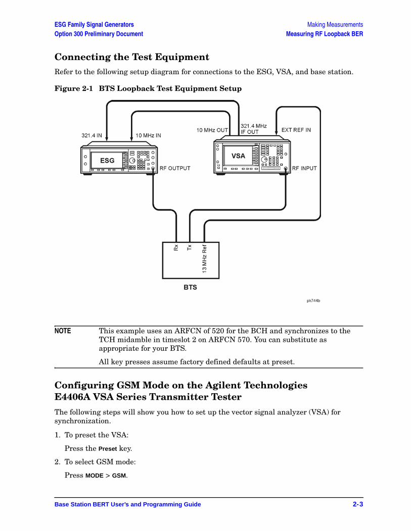
Connecting the Test EquipmentRefer to the following setup diagram for connections to the ESG, VSA, and base station.
Figure 2-1 BTS Loopback Test Equipment Setup
NOTE This example uses an ARFCN of 520 for the BCH and synchronizes to the TCH midamble in timeslot 2 on ARFCN 570. You can substitute as appropriate for your BTS.
All key presses assume factory defined defaults at preset.
Configuring GSM Mode on the Agilent Technologies E4406A VSA Series Transmitter Tester
The following steps will show you how to set up the vector signal analyzer (VSA) for synchronization.
1. To preset the VSA:
Press the Preset key.
2. To select GSM mode:
Press MODE > GSM.
Making Measurements ESG Family Signal GeneratorsMeasuring RF Loopback BER Option 300 Preliminary Document
2-4 Base Station BERT User’s and Programming Guide
3. To set up GSM mode for BTS test:
Press Mode Setup > Radio > Band > DCS 1800.
Toggle Device BTS MS until BTS is underlined.
Toggle Freq Hopping On Off until Off is underlined.
4. To set the frequency:
Press FREQUENCY Channel > Center Freq.
Enter 1.8068 > GHz.
Select Burst Type > Normal.
Toggle TSC Auto Manual until Auto is underlined.
5. To lock the VSA and ESG to the BTS 13 MHz reference:
Press System > Reference.
Press Freq Ref > 13 > MHz.
Toggle Freq Ref Int Ext until Ext is underlined.
Toggle 10 MHz Out Off On until On is underlined.
Configuring GSM Mode on the ESG-D Series Signal GeneratorThe following steps will show you how to configure a timeslot with multiframe data, set up traffic channel 570, and set the frequency and amplitude in GSM mode on the signal generator.
When configuring a timeslot in this procedure, keep the following points in mind:
• Prior to synchronization, the transmitter must be configured to generate multiframe data in the timeslot to be tested.
• TCH synchronization requires that the training sequences match between the ESG timeslot configuration and the timeslot sent by the base station. The default for the ESG, which is TSC0, can be modified.
1. Press Preset.
2. Press MODE > BERT > BTS BERT GSM Loopback > Configure Measurement > Transmit Settings.
3. Press the GSM On Off softkey. On is now highlighted.
4. Press the Data Format Pattern Framed softkey. Framed is now highlighted.
ESG Family Signal Generators Making MeasurementsOption 300 Preliminary Document Measuring RF Loopback BER
Base Station BERT User’s and Programming Guide 2-5
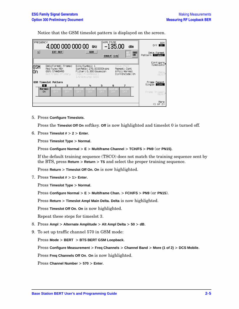
Notice that the GSM timeslot pattern is displayed on the screen.
5. Press Configure Timeslots.
Press the Timeslot Off On softkey. Off is now highlighted and timeslot 0 is turned off.
6. Press Timeslot # > 2 > Enter.
Press Timeslot Type > Normal.
Press Configure Normal > E > Multiframe Channel > TCH/FS > PN9 (or PN15).
If the default training sequence (TSCO) does not match the training sequence sent by the BTS, press Return > Return > TS and select the proper training sequence.
Press Return > Timeslot Off On. On is now highlighted.
7. Press Timeslot # > 1> Enter.
Press Timeslot Type > Normal.
Press Configure Normal > E > Multiframe Chan. > FCH/FS > PN9 (or PN15).
Press Return > Timeslot Ampl Main Delta. Delta is now highlighted.
Press Timeslot Off On. On is now highlighted.
Repeat these steps for timeslot 3.
8. Press Ampl > Alternate Amplitude > Alt Ampl Delta > 50 > dB.
9. To set up traffic channel 570 in GSM mode:
Press Mode > BERT > BTS BERT GSM Loopback.
Press Configure Measurement > Freq Channels > Channel Band > More (1 of 2) > DCS Mobile.
Press Freq Channels Off On. On is now highlighted.
Press Channel Number > 570 > Enter.

Making Measurements ESG Family Signal GeneratorsMeasuring RF Loopback BER Option 300 Preliminary Document
2-6 Base Station BERT User’s and Programming Guide
Notice that the active entry area displays the following:Channel: 570 (1.72180000000GHz)
10.Press Amplitude > −104 > dBm.
11.Press the RF On/Off hardkey to turn the RF output on.
Notice that the RF annunciator is turned on and the new power level is shown in the amplitude area of the display:
ESG Family Signal Generators Making MeasurementsOption 300 Preliminary Document Measuring RF Loopback BER
Base Station BERT User’s and Programming Guide 2-7
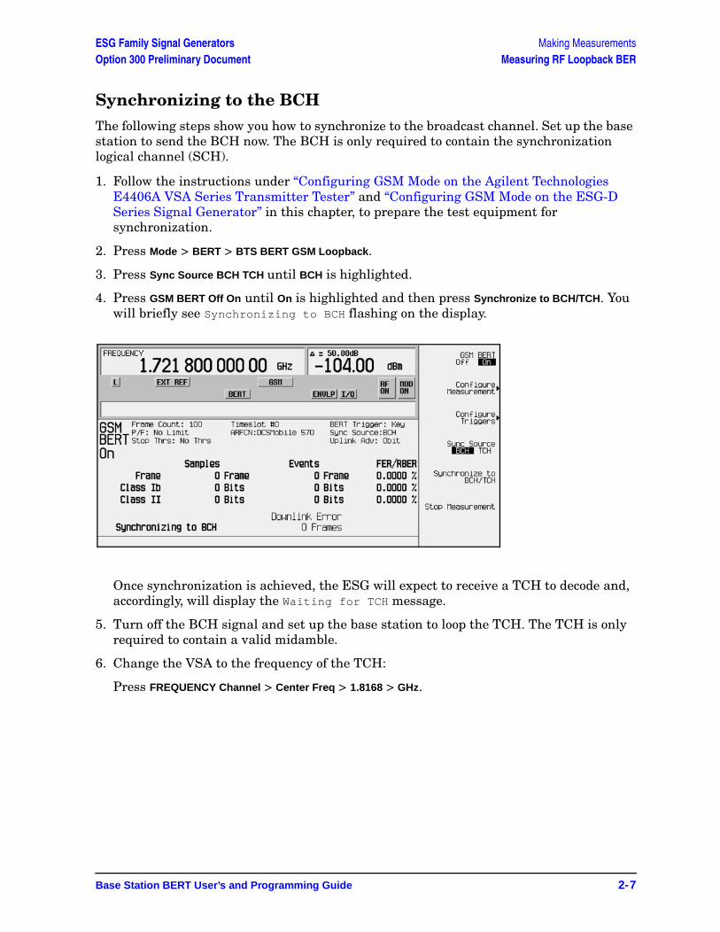
Synchronizing to the BCHThe following steps show you how to synchronize to the broadcast channel. Set up the base station to send the BCH now. The BCH is only required to contain the synchronization logical channel (SCH).
1. Follow the instructions under “Configuring GSM Mode on the Agilent Technologies E4406A VSA Series Transmitter Tester” and “Configuring GSM Mode on the ESG-D Series Signal Generator” in this chapter, to prepare the test equipment for synchronization.
2. Press Mode > BERT > BTS BERT GSM Loopback.
3. Press Sync Source BCH TCH until BCH is highlighted.
4. Press GSM BERT Off On until On is highlighted and then press Synchronize to BCH/TCH. You will briefly see Synchronizing to BCH flashing on the display.
Once synchronization is achieved, the ESG will expect to receive a TCH to decode and, accordingly, will display the Waiting for TCH message.
5. Turn off the BCH signal and set up the base station to loop the TCH. The TCH is only required to contain a valid midamble.
6. Change the VSA to the frequency of the TCH:
Press FREQUENCY Channel > Center Freq > 1.8168 > GHz.
Making Measurements ESG Family Signal GeneratorsMeasuring RF Loopback BER Option 300 Preliminary Document
2-8 Base Station BERT User’s and Programming Guide
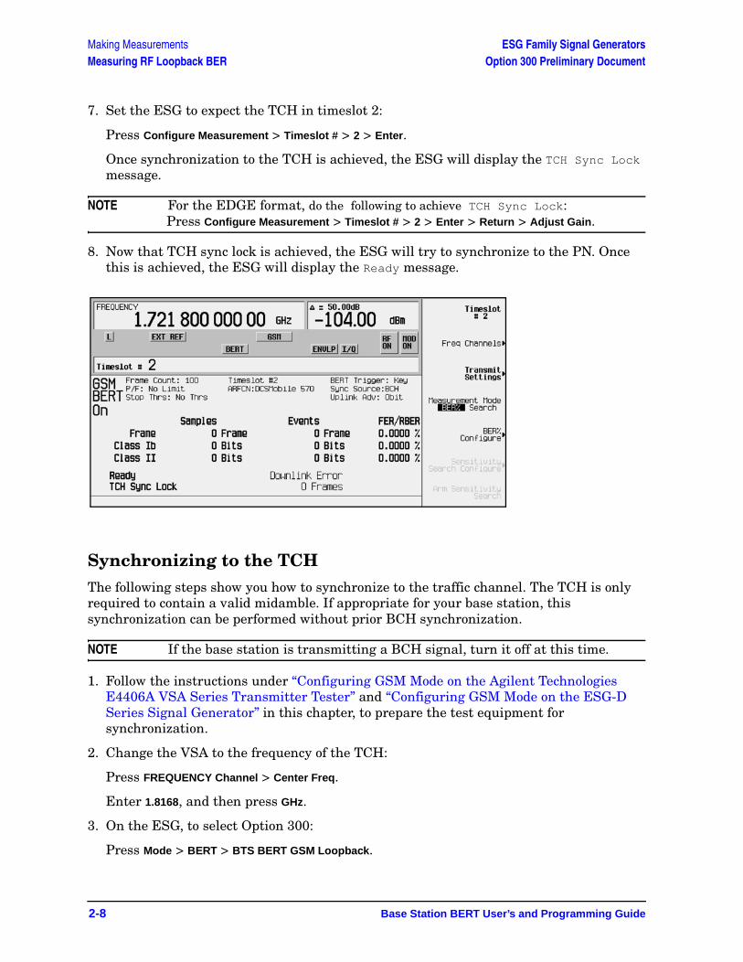
7. Set the ESG to expect the TCH in timeslot 2:
Press Configure Measurement > Timeslot # > 2 > Enter.
Once synchronization to the TCH is achieved, the ESG will display the TCH Sync Lock message.
NOTE For the EDGE format, do the following to achieve TCH Sync Lock:Press Configure Measurement > Timeslot # > 2 > Enter > Return > Adjust Gain.
8. Now that TCH sync lock is achieved, the ESG will try to synchronize to the PN. Once this is achieved, the ESG will display the Ready message.
Synchronizing to the TCHThe following steps show you how to synchronize to the traffic channel. The TCH is only required to contain a valid midamble. If appropriate for your base station, this synchronization can be performed without prior BCH synchronization.
NOTE If the base station is transmitting a BCH signal, turn it off at this time.
1. Follow the instructions under “Configuring GSM Mode on the Agilent Technologies E4406A VSA Series Transmitter Tester” and “Configuring GSM Mode on the ESG-D Series Signal Generator” in this chapter, to prepare the test equipment for synchronization.
2. Change the VSA to the frequency of the TCH:
Press FREQUENCY Channel > Center Freq.
Enter 1.8168, and then press GHz.
3. On the ESG, to select Option 300:
Press Mode > BERT > BTS BERT GSM Loopback.
ESG Family Signal Generators Making MeasurementsOption 300 Preliminary Document Measuring RF Loopback BER
Base Station BERT User’s and Programming Guide 2-9
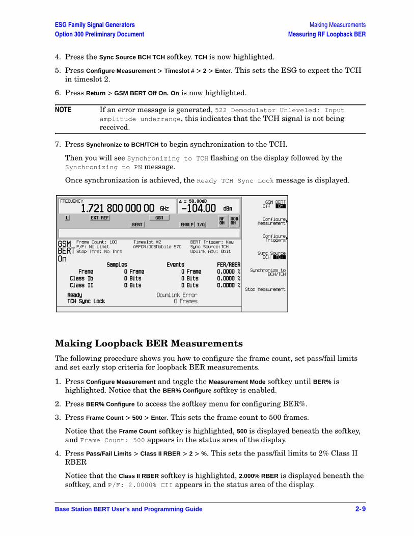
4. Press the Sync Source BCH TCH softkey. TCH is now highlighted.
5. Press Configure Measurement > Timeslot # > 2 > Enter. This sets the ESG to expect the TCH in timeslot 2.
6. Press Return > GSM BERT Off On. On is now highlighted.
NOTE If an error message is generated, 522 Demodulator Unleveled; Input amplitude underrange, this indicates that the TCH signal is not being received.
7. Press Synchronize to BCH/TCH to begin synchronization to the TCH.
Then you will see Synchronizing to TCH flashing on the display followed by the Synchronizing to PN message.
Once synchronization is achieved, the Ready TCH Sync Lock message is displayed.
Making Loopback BER MeasurementsThe following procedure shows you how to configure the frame count, set pass/fail limits and set early stop criteria for loopback BER measurements.
1. Press Configure Measurement and toggle the Measurement Mode softkey until BER% is highlighted. Notice that the BER% Configure softkey is enabled.
2. Press BER% Configure to access the softkey menu for configuring BER%.
3. Press Frame Count > 500 > Enter. This sets the frame count to 500 frames.
Notice that the Frame Count softkey is highlighted, 500 is displayed beneath the softkey, and Frame Count: 500 appears in the status area of the display.
4. Press Pass/Fail Limits > Class II RBER > 2 > %. This sets the pass/fail limits to 2% Class II RBER
Notice that the Class II RBER softkey is highlighted, 2.000% RBER is displayed beneath the softkey, and P/F: 2.0000% CII appears in the status area of the display.
Making Measurements ESG Family Signal GeneratorsMeasuring RF Loopback BER Option 300 Preliminary Document
2-10 Base Station BERT User’s and Programming Guide
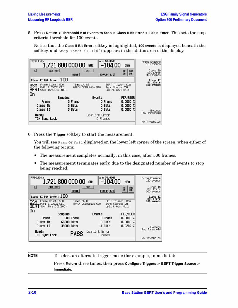
5. Press Return > Threshold # of Events to Stop > Class II Bit Error > 100 > Enter. This sets the stop criteria threshold for 100 events
Notice that the Class II Bit Error softkey is highlighted, 100 events is displayed beneath the softkey, and Stop Thrs: CII(100) appears in the status area of the display.
6. Press the Trigger softkey to start the measurement:
You will see Pass or Fail displayed on the lower left corner of the screen, when either of the following occurs:
• The measurement completes normally; in this case, after 500 frames.
• The measurement terminates early, due to the designated number of events to stop being reached.
NOTE To select an alternate trigger mode (for example, Immediate):
Press Return three times, then press Configure Triggers > BERT Trigger Source > Immediate.
ESG Family Signal Generators Making MeasurementsOption 300 Preliminary Document Measuring RF Loopback BER
Base Station BERT User’s and Programming Guide 2-11
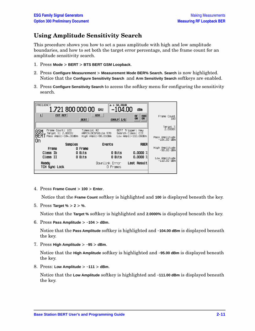
Using Amplitude Sensitivity SearchThis procedure shows you how to set a pass amplitude with high and low amplitude boundaries, and how to set both the target error percentage, and the frame count for an amplitude sensitivity search.
1. Press Mode > BERT > BTS BERT GSM Loopback.
2. Press Configure Measurement > Measurement Mode BER% Search. Search is now highlighted. Notice that the Configure Sensitivity Search and Arm Sensitivity Search softkeys are enabled.
3. Press Configure Sensitivity Search to access the softkey menu for configuring the sensitivity search.
4. Press Frame Count > 100 > Enter.
Notice that the Frame Count softkey is highlighted and 100 is displayed beneath the key.
5. Press Target % > 2 > %.
Notice that the Target % softkey is highlighted and 2.0000% is displayed beneath the key.
6. Press Pass Amplitude > −104 > dBm.
Notice that the Pass Amplitude softkey is highlighted and −104.00 dBm is displayed beneath the key.
7. Press High Amplitude > −95 > dBm.
Notice that the High Amplitude softkey is highlighted and −95.00 dBm is displayed beneath the key.
8. Press: Low Amplitude > −111 > dBm.
Notice that the Low Amplitude softkey is highlighted and −111.00 dBm is displayed beneath the key.
Making Measurements ESG Family Signal GeneratorsMeasuring RF Loopback BER Option 300 Preliminary Document
2-12 Base Station BERT User’s and Programming Guide
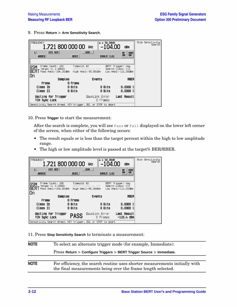
9. Press Return > Arm Sensitivity Search.
10. Press Trigger to start the measurement:
After the search is complete, you will see Pass or Fail displayed on the lower left corner of the screen, when either of the following occurs:
• The result equals or is less than the target percent within the high to low amplitude range.
• The high or low amplitude level is passed at the target% BER/RBER.
11. Press Stop Sensitivity Search to terminate a measurement:
NOTE To select an alternate trigger mode (for example, Immediate):
Press Return > Configure Triggers > BERT Trigger Source > Immediate.
NOTE For efficiency, the search routine uses shorter measurements initially with the final measurements being over the frame length selected.
ESG Family Signal Generators Making MeasurementsOption 300 Preliminary Document Using the External Frame Trigger Function with the EDGE Format
Base Station BERT User’s and Programming Guide 2-13
Using the External Frame Trigger Function with the EDGE Format
NOTE This function is available only when the Frame Trigger Source BCH PDCH is set to PDCH.
The External Frame Trigger Function is used to adjust the burst timing at PDCH synchronization. This requires calculating a delay value and then adjusting the initial value.
Measuring the Initial Delay Value
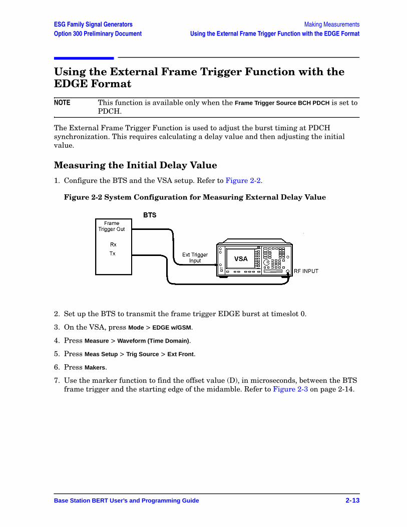
1. Configure the BTS and the VSA setup. Refer to Figure 2-2.
Figure 2-2 System Configuration for Measuring External Delay Value
2. Set up the BTS to transmit the frame trigger EDGE burst at timeslot 0.
3. On the VSA, press Mode > EDGE w/GSM.
4. Press Measure > Waveform (Time Domain).
5. Press Meas Setup > Trig Source > Ext Front.
6. Press Makers.
7. Use the marker function to find the offset value (D), in microseconds, between the BTS frame trigger and the starting edge of the midamble. Refer to Figure 2-3 on page 2-14.
Making Measurements ESG Family Signal GeneratorsUsing the External Frame Trigger Function with the EDGE Format Option 300 Preliminary Document
2-14 Base Station BERT User’s and Programming Guide
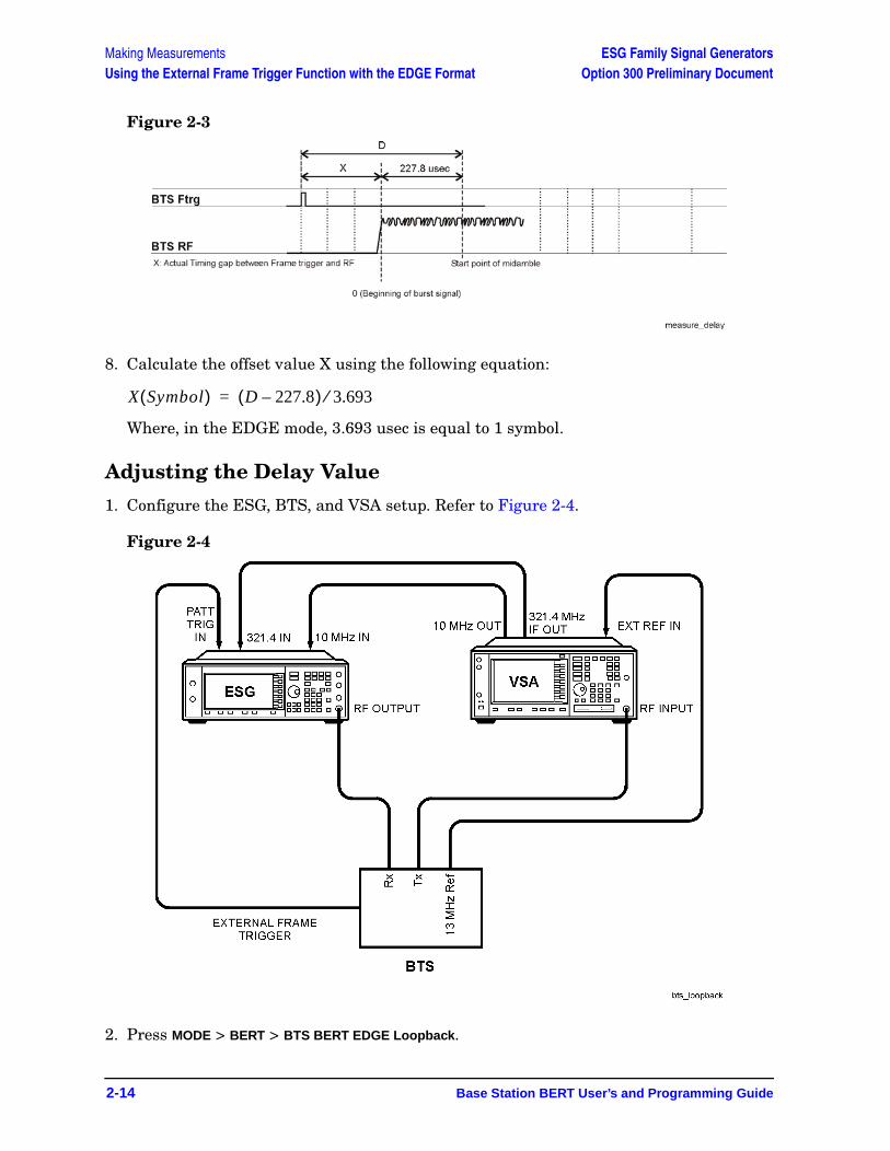
Figure 2-3
8. Calculate the offset value X using the following equation:
Where, in the EDGE mode, 3.693 usec is equal to 1 symbol.
Adjusting the Delay Value
1. Configure the ESG, BTS, and VSA setup. Refer to Figure 2-4.
Figure 2-4
2. Press MODE > BERT > BTS BERT EDGE Loopback.
X Symbol( ) D 227.8–( ) 3.693⁄=
ESG Family Signal Generators Making MeasurementsOption 300 Preliminary Document Using the External Frame Trigger Function with the EDGE Format
Base Station BERT User’s and Programming Guide 2-15
3. Press EDGE BERT to On > Configure Triggers.
4. Press Frame Trigger Source BCH PDCH to PDCH.
5. Press Configure Triggers > Frame Trigger Source Int Ext to Ext.
6. Press Ext Frame Trigger Delay and enter the X value calculated in the previous section.
NOTE If the frame trigger is in the forward direction of timeslot 0, as shown in Figure 2-3 on page 2-14, enter the X value as a negative value.
7. Press Return > Synchronize to BCH/PDCH.
Synchronization should occur and display a Ready status. However, if Synchronizing keeps flashing or the Ready status appears for less than a second, increase or decrease the delay value by 2 symbols and press the Synchronize to BCH/PDCH softkey again. Repeat this process until the Ready status (synchronization) becomes stable.
8. Press Configure Triggers > Ext Frame Trigger Delay.
9. Change the delay value by rotating the knob slowly to find the range of delay values that display a Ready status.
NOTE Although the delay value can be entered in 0.25 units, the actual uplink burst position can be changed in 1.0 symbol units.
10. If the PDCH is synchronized by a delay value within a ±3 symbol range, choose the center value to set as the frame trigger delay.

Making Measurements ESG Family Signal GeneratorsUsing the External Frame Trigger Function with the EDGE Format Option 300 Preliminary Document
2-16 Base Station BERT User’s and Programming Guide
Base Station BERT User’s and Programming Guide 3-1
ESG Family Signal GeneratorsOption 300 Preliminary Document
3 Softkey Reference
This chapter describes the Mode hardkey, and explains the associated softkeys that are used to activate functions specific to the Agilent Technologies ESG-D Option 300, Base Station BERT.
3-2 Base Station BERT User’s and Programming Guide
Softkey Reference ESG Family Signal GeneratorsGSM/EDGE Base Station Test Softkeys Option 300 Preliminary Document
GSM/EDGE Base Station Test SoftkeysAccess the following Option 300 softkeys to perform GSM BTS loopback, EDGE BTS loopback, and Baseband BER tests.
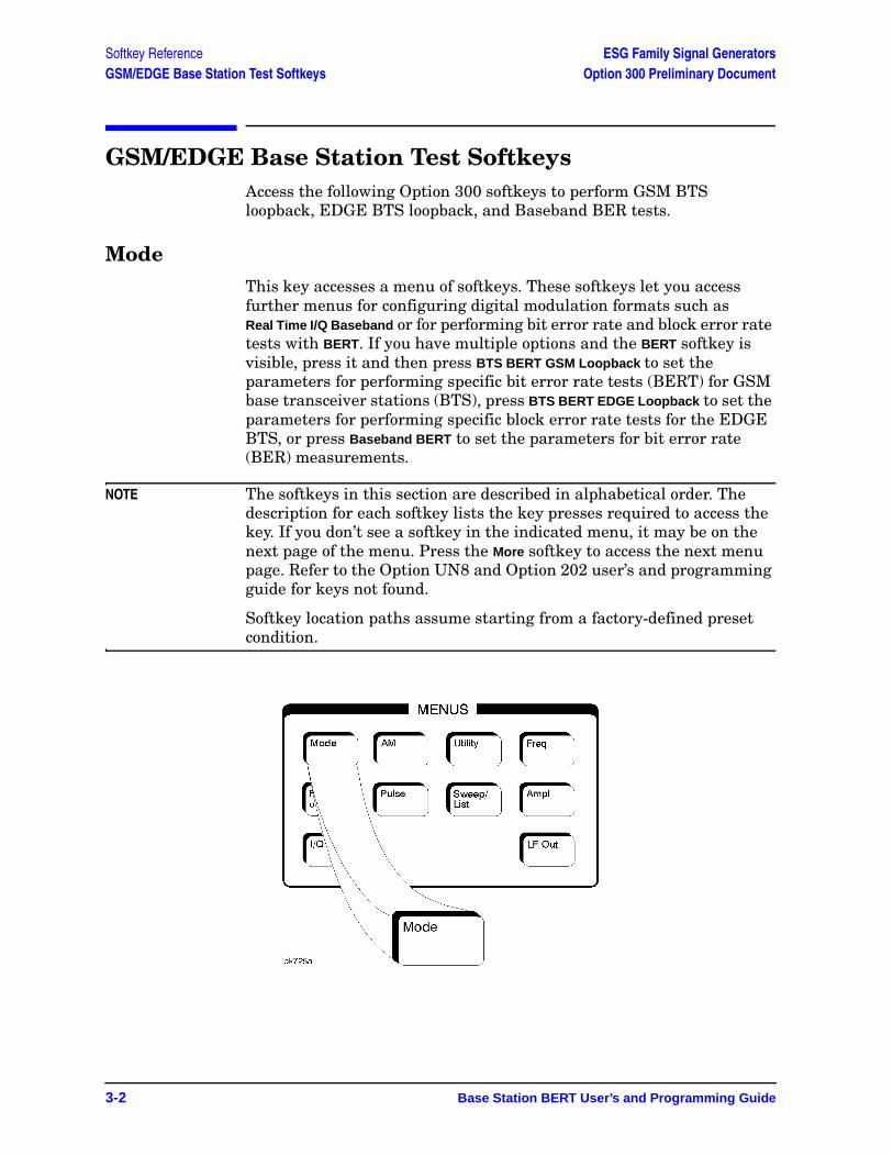
ModeThis key accesses a menu of softkeys. These softkeys let you access further menus for configuring digital modulation formats such as Real Time I/Q Baseband or for performing bit error rate and block error rate tests with BERT. If you have multiple options and the BERT softkey is visible, press it and then press BTS BERT GSM Loopback to set the parameters for performing specific bit error rate tests (BERT) for GSM base transceiver stations (BTS), press BTS BERT EDGE Loopback to set the parameters for performing specific block error rate tests for the EDGE BTS, or press Baseband BERT to set the parameters for bit error rate (BER) measurements.
NOTE The softkeys in this section are described in alphabetical order. The description for each softkey lists the key presses required to access the key. If you don’t see a softkey in the indicated menu, it may be on the next page of the menu. Press the More softkey to access the next menu page. Refer to the Option UN8 and Option 202 user’s and programming guide for keys not found.
Softkey location paths assume starting from a factory-defined preset condition.
Base Station BERT User’s and Programming Guide 3-3
ESG Family Signal Generators Softkey ReferenceOption 300 Preliminary Document GSM/EDGE Base Station Test Softkeys
Adjust GainThis adjustment is necessary to start the synchronization with the PDCH channel for the EDGE format. Therefore, this key must be used when switching the synchronization source from the broadcast channel (BCH), GMSK modulation, to a packet data channel (PDCH), EDGE modulation.
This key is only enabled when EDGE BERT Off On is set to On.
Softkey Location (EDGE): Mode > BERT > BTS BERT EDGE Loopback > Adjust Gain
Arm Sensitivity Search
This key arms the sensitivity search function. Once sensitivity search is armed, the sensitivity search operation will run upon receiving the selected trigger. (If Trigger Key is selected, press the Trigger hardkey to start the search.) Press Stop Sensitivity Search to end the search prematurely. During search, no other softkey operation is available except Stop Sensitivity Search.
Softkey Location (GSM): Mode > BERT > BTS BERT GSM Loopback > Configure Measurement > Arm Sensitivity Search
Softkey Location (EDGE): Mode > BERT > BTS BERT EDGE Loopback > Configure Measurement > Arm Sensitivity Search
Baseband BERT This key accesses a menu of softkeys that enable you to set or specify all of the parameters required to configure a bit error rate test (BERT) for digital communication equipment.
Softkey Location (Baseband): Mode > BERT > Baseband BERT
BER% Uncoded ConfigureThis key accesses a menu where you can select BER% Uncoded configuration functions such as setting the bit count, the pass/fail limits, and the stop-on-event thresholds.
Softkey Location (EDGE): Mode > BERT > BTS BERT EDGE Loopback > Configure Measurement > BLER% Configure > BER% Uncoded Configure

3-4 Base Station BERT User’s and Programming Guide
Softkey Reference ESG Family Signal GeneratorsGSM/EDGE Base Station Test Softkeys Option 300 Preliminary Document
BER Mode Off OnThis key toggles the BER mode off or on. The BER on mode tracks the number of blocks that contain bit errors.
Softkey Location (EDGE): Mode > BERT > BTS BERT EDGE Loopback > Configure Measurement > BLER% Configure > BLER% MCS5 Configure orBLER% MCS9 Configure,> BER Mode Off ON
BERT
This key accesses a menu of softkeys that enable you to select the type of bit error rate test (BERT). The choices are Baseband BERT, BTS BERT GSM Loopback, or BTS BERT EDGE Loopback.
Softkey Location: Mode > BERT
BERT Off OnPress this key to enable and disable the BER measurement function.
Default value: Off
Softkey Location (Baseband BERT): Mode > BERT > Baseband BERT > BERT Off On
BERT Resync Off OnSets the operating state of the resynchronizing function. This key is valid only when the Max. Data Rate 2Mbps 10Mbps key is set to 2Mbps. When you select On, a new BER measurement will immediately be restarted whenever the previous BER measurement result exceeds the value specified by the Resync Limits key.
Default value: On
Softkey Location (Baseband BERT): Mode > BERT > Baseband BERT > Configure BERT > Max. Data Rate 2Mbps > BERT Resync Off On
BERT TriggerThis key accesses a menu of choices for triggering BER measurements. You can choose triggering that occurs immediately (Immediate), triggering by the front panel Trigger key (Trigger Key), triggering that is supplied by the GPIB (Bus), or triggering on the positive edge of a signal supplied to the TRIGGER IN connector (Ext).
Softkey Location (Baseband BERT): Mode > BERT > Baseband BERT > Configure Trigger > BERT Trigger
Base Station BERT User’s and Programming Guide 3-5
ESG Family Signal Generators Softkey ReferenceOption 300 Preliminary Document GSM/EDGE Base Station Test Softkeys
BERT Trigger Source
This key accesses a menu of choices for selecting the BERT trigger source. You can choose triggering that occurs immediately (Immediate), triggering by the Trigger hardkey (Trigger Key), triggering that is supplied remotely via GPIB (Bus), or triggering on an external signal supplied to the TRIGGER IN connector (Ext).
Default Value: Trigger Key
Softkey Location (GSM): Mode > BERT > BTS BERT GSM Loopback > Configure Triggers > BERT Trigger Source
Softkey Location (EDGE): Mode > BERT > BTS BERT EDGE Loopback > Configure Triggers > BERT Trigger Source
Bit Count This key enables you to specify the total number of bits to be measured for the uncoded EDGE channel.
Range: 0 through 2147483647
Default Value: 139200.
Softkey Location (EDGE): Mode > BERT > BTS BERT EDGE Loopback > Configure Measurement > BLER% Configure > BER% Uncoded Configure > Bit CountOr: Mode > BERT > BTS BERT EDGE Loopback > Configure Measurement > Measurement Mode BLER% Search > Sensitivity Search Configure > Search Uncoded Configure > Bit Count
Bit Delay Off OnUse this key to toggle the trigger delay for BER measurements on or off.
Default Value: Off
Softkey Location (Baseband BERT): Mode > BERT > Baseband BERT > Configure Trigger > Bit Delay Off On
BLER% MCS5 ConfigureThis key accesses a menu where you can select BLER% MCS5 configuration functions such as setting the block count, the pass/fail limits, the stop-on-event thresholds, and turn the bit error rate mode off and on.
Softkey Location (EDGE): Mode > BERT > BTS BERT EDGE Loopback > Configure Measurement > BLER% Configure > BLER% MCS5 Configure
3-6 Base Station BERT User’s and Programming Guide
Softkey Reference ESG Family Signal GeneratorsGSM/EDGE Base Station Test Softkeys Option 300 Preliminary Document
BLER% MCS9 ConfigureThis key accesses a menu where you can select BLER% MCS9 configuration functions such as setting the block count, the pass/fail limits, the stop-on-event thresholds, and turn the bit error rate mode off and on.
Softkey Location (EDGE): Mode > BERT > BTS BERT EDGE Loopback > Configure Measurement > BLER% Configure > BLER% MCS9 Configure
BLER% ConfigureThis key accesses a menu where you can select BLER% configuration functions.
Softkey Location (EDGE): Mode > BERT > BTS BERT EDGE Loopback > Configure Measurement > BLER% Configure
Block Count This key enables you to specify the number of data blocks to be measured at each measurement on the MCS5 or MCS9 channels.
NOTE For MCS-9, only even values can be entered with a minimum value of 2. If odd numbers are entered, a +1 will be added to the value to make it an even value
Range: 1 to 1,500,000
Softkey Location (EDGE): Mode > BERT > BTS BERT EDGE Loopback > Configure Measurement > BLER% Configure > BLER% MCS5 Configure, orBLER% MCS9 Configure > Block Count
Or: Mode > BERT > BTS BERT EDGE Loopback > Configure Measurement > Measurement Mode BLER% Search > Sensitivity Search Configure > Search DL MCS5 Configure or Search DL MCS9 Configure > Block Count
Block Erasure This key enables you to set the block erasure threshold. If the number of erased blocks exceeds this value the measurement will end.
Range: 0 to 1,000,000 frames
Softkey Location (EDGE): Mode > BERT > BTS BERT EDGE Loopback > Configure Measurement > BLER% Configure > BLER% MCS5 Configure orBLER% MCS9 Configure > Threshold # of Events to Stop > Block Erasure

Base Station BERT User’s and Programming Guide 3-7
ESG Family Signal Generators Softkey ReferenceOption 300 Preliminary Document GSM/EDGE Base Station Test Softkeys
BTS BERT EDGE LoopbackThis key accesses a menu of softkeys that enable you to set or specify all of the parameters required to configure the EDGE base transceiver station bit error rate test (BTS BERT).
Softkey Location (EDGE): Mode > BERT > BTS BERT EDGE Loopback
BTS BERT GSM Loopback
This key accesses the menu of softkeys that enable you to set or specify all of the parameters required to configure the GSM base transceiver station bit error rate tests (BTS BERT).
Softkey Location (GSM): Mode > BERT > BTS BERT GSM Loopback
Bus
This key enables a measurement to run when the appropriate GPIB command is received, provided synchronization has already been achieved. If not already synchronized, the trigger is ignored.
Default Value: Trigger Key
Softkey Location (GSM): Mode > BERT > BTS BERT GSM Loopback > Configure Triggers > BERT Trigger Source > Bus
Softkey Location (EDGE): Mode > BERT > BTS BERT EDGE Loopback > Configure Triggers > BERT Trigger Source > Bus
Softkey Location (Baseband BERT): Mode > BERT > Baseband BERT > Configure Trigger > BERT Trigger > Bus
Channel Band
This key accesses a menu of choices for assigning channel bands based on the current format. The output frequency depends on both the channel band and channel number selections.
Softkey Location (GSM): Mode > BERT > BTS BERT GSM Loopback > Configure Measurement > Freq Channels > Channel Band
Softkey Location (EDGE): Mode > BERT > BTS BERT EDGE Loopback > Configure Measurement > Freq Channels > Channel Band
3-8 Base Station BERT User’s and Programming Guide
Softkey Reference ESG Family Signal GeneratorsGSM/EDGE Base Station Test Softkeys Option 300 Preliminary Document
Channel Number
This key enables you to change the channel numbers (the frame carrier frequency) based on frequency channels. To change the channel number, rotate the front panel knob until the desired value is displayed, use the up and down arrow keys, or enter the value using the numeric keypad. The output frequency depends on both the channel band and channel number selections.
Default Value: 0
Softkey Location (GSM): Mode > BERT > BTS BERT GSM Loopback > Configure Measurement > Freq Channels > Channel Number
Softkey Location (EDGE): Mode > BERT > BTS BERT EDGE Loopback > Configure Measurement > Freq Channels > Channel Number
Class Ib Bit Error
This key ends the measurement when the detected number of Class Ib errors exceeds the set threshold.
Range: 0 through 1,000,000 events.
Default Value: 300 events
Softkey Location (GSM): Mode > BERT > BTS BERT GSM Loopback> Configure Measurement > Configure BER% > Threshold # of Events to Stop > Class Ib Bit Error
Class Ib RBER
This key enables you to set the pass/fail Class Ib RBER limit. Class Ib RBER is the ratio of the number of errored Class Ib bits (after de-convolution in the non-erased speech frames) to the total number of Class Ib bits in the non-erased frames. The measurement fails if the Class Ib RBER exceeds a threshold.
Range: 0% through 100% (0 to 1)
Default Value: 0.4000% RBER
Softkey Location (GSM): Mode > BERT > BTS BERT GSM Loopback > Configure Measurement > Configure BER% > Pass/Fail Limits > Class Ib RBER

Base Station BERT User’s and Programming Guide 3-9
ESG Family Signal Generators Softkey ReferenceOption 300 Preliminary Document GSM/EDGE Base Station Test Softkeys
Class II Bit Error
This key ends the measurement when the detected number of Class II errors exceeds the set threshold.
Range: 0 through 1,000,000 events
Default Value: 300 events
Softkey Location (GSM): Mode > BERT > BTS BERT GSM Loopback > Configure Measurement > Configure BER% > Threshold # of Events to Stop > Class II Bit Error
Class II RBER
This key enables you to set the Pass/Fail Class II RBER limit. Class II RBER is the ratio of the number of errored Class II bits (after de-convolution in the non-erased speech frames) to the total number of Class II bits in the non-erased frames. The measurement fails if the Class II RBER exceeds a threshold.
Range: 0% through 100% (0 to 1)
Default Value: 2.0000% RBER
Softkey Location (GSM): Mode > BERT > BTS BERT GSM Loopback > Configure Measurement > Configure BER% > Pass/Fail Limits > Class II RBER
Clock Gate Off OnThis key toggles the clock gate function off and on. When you select On, the clock signal is valid when the clock gate signal is high for the normal (positive) mode, or low for the inverted (negative) mode. This clock gate signal is connected to the rear panel BER GATE IN connector.
Default value: Off
Softkey Location (Baseband BERT): Mode > BERT > Baseband BERT > Configure BERT > Clock Gate Off On
Clock Gate Polarity Neg PosUse this key to input the polarity of the clock gate signal supplied to the rear panel BER GATE IN connector. When you select Pos (positive), the clock signal is valid when the clock gate signal is high; when you select Neg (negative), the clock signal is valid when the clock gate signal is low.
Default value: Pos
Softkey Location (Baseband BERT): Mode > BERT > Baseband BERT > Configure BERT > Clock Gate On > Clock Gate Polarity Neg Pos
3-10 Base Station BERT User’s and Programming Guide
Softkey Reference ESG Family Signal GeneratorsGSM/EDGE Base Station Test Softkeys Option 300 Preliminary Document
Clock Polarity Neg PosInputs polarity of the clock signal supplied to the rear panel BER GATE IN connector. When you select Pos (positive), the rising edge is used; when you select Neg (negative), the falling edge is used.
Default value: Pos (Positive)
Softkey Location (Baseband BERT): Mode > BERT > Baseband BERT > Configure BERT > Clock Polarity Neg Pos
Configure BER%
This key accesses the BER% configuration functions such as setting the frame count, the pass/fail limits, and the stop-on-event thresholds.
Softkey Location (GSM): Mode > BERT > BTS BERT GSM Loopback > Configure Measurement > Configure BER%
Configure BERTUse this key to access more menus for configuring test parameters for BER measurements.
Softkey Location (Baseband BERT): Mode > BERT > Baseband BERT > Configure BERT
Configure Measurement
This key accesses a menu of softkeys that enable you to configure the test parameters for BTS BER measurements.
Softkey Location (GSM): Mode > BERT > BTS BERT GSM Loopback > Configure Measurement
Softkey Location (EDGE): Mode > BERT > BTS BERT EDGE Loopback > Configure Measurement
Configure Sensitivity SearchThis key accesses a menu of keys that enable you to configure the parameters for the sensitivity search function.
Softkey Location (GSM): Mode > BERT > BTS BERT GSM Loopback > Configure Measurement > Measurement Mode BER% Search > Configure Sensitivity Search
Base Station BERT User’s and Programming Guide 3-11
ESG Family Signal Generators Softkey ReferenceOption 300 Preliminary Document GSM/EDGE Base Station Test Softkeys
Configure Triggers
This key accesses the menu of softkeys that enable you to select the BERT trigger source, uplink timing advance, and inverting the spectrum.
Softkey Location (GSM): Mode > BERT > BTS BERT GSM Loopback > Configure Triggers
Softkey Location (EDGE): Mode > BERT > BTS BERT EDGE Loopback > Configure Triggers
Cycle CountThis key enables you to specify the number of repetitions of BER measurements. The range of the acceptable values is from 0 to 65,535. With 0 set, the BER measurements are repeated till you set the BERT Off On key to Off. Enter the value using the numeric keypad and terminate it by pressing the Enter key.
Default value: 1
Softkey Location (Baseband BERT): Mode > BERT > Baseband BERT > Configure Trigger > Cycle Count
Cycle EndThis key is one of the choices in the Pass/Fail Update menu. With Cycle End selected, a pass or fail judgement is made for each BER measurement result.
Softkey Location (Baseband BERT): Mode > BERT > Baseband BERT > Configure BERT > Pass/Fail Off On > Pass/Fail Update > Cycle End
DataPress this key to access a menu of choices for the incoming data pattern to the BER DATA IN connector with either PN9 or PN15.
NOTE Be sure to match this value to the data pattern in the traffic channel (TCH) of the RF signal which is input to the radio under test.
Default value: PN9
Softkey Location (Baseband BERT): Mode > BERT > Baseband BERT > Configure BERT > Data
3-12 Base Station BERT User’s and Programming Guide
Softkey Reference ESG Family Signal GeneratorsGSM/EDGE Base Station Test Softkeys Option 300 Preliminary Document
Data Polarity Neg PosUse this key to set the input polarity of the data signal supplied to the rear panel BER DATA IN connector. When you select Pos (positive), the data signal is used as it is; when you select Neg (negative), the polarity of the data signal is inverted.
Default value: Pos
Softkey Location (Baseband BERT): Mode > BERT > Baseband BERT > Configure BERT > Data Polarity Pos Neg
Delayed BitsThis key enables you to specify the number of delay bits from the trigger event for starting BER measurements. This key is valid only when the BERT Trigger Bit Delay key is set to On. Enter the value using the numeric keypad and terminate it by pressing the Enter key.
Range: 0−65,535
Default value: 0
Softkey Location (Baseband BERT): Mode > BERT > Baseband BERT > Configure Trigger > Bit Delay On > Delayed Bits
Display BER % ExpThis key enables you to set the display mode for BER measurement results. When you select %, the BER measurement results are displayed in percent. When you select Exp, the BER measurement results are displayed in the exponential format of n.nnnnnE-mm.
Default value: %
Softkey Location (Baseband BERT): Mode > BERT > Baseband BERT > Display BER % Exp
Display Update Cycle End ContUse this key to display the update mode during BER measurements. When you select Cycle End, the previous BER measurement result is displayed during the current measurement cycle. When you select Cont, the display shows its real-time intermediate results during each BER measurement. This key is valid only when the Max. Data Rate 2Mbps 10Mbps key is set to 2Mbps.
Default Value: Cycle End
Softkey Location (Baseband BERT): Mode > BERT > Baseband BERT > Display Update Cycle End Cont
Base Station BERT User’s and Programming Guide 3-13
ESG Family Signal Generators Softkey ReferenceOption 300 Preliminary Document GSM/EDGE Base Station Test Softkeys
Downlink MCS-1Press this softkey to select a downlink packet data traffic channel with block type 5 that is in compliance with GSM 05.03.
Softkey Location(GSM): Mode > BERT > BTS BERT GSM Loopback > Configure Measurement > Transmit Settings > Data Format Pattern Framed > Configure Timeslots > Configure Normal > E > Multiframe Channel > Downlink MCS-1
Downlink MCS-5Press this key to select a downlink packet data traffic channel with block type 9 that is in compliance with GSM 05.03. The MCS5 radio block contains a single RLC data block of 448 bits with a code rate of 0.37. This ensures that the maximum amount of Forward Error Correction (FEC) has been applied to the data.
Softkey Location (EDGE): Mode > BERT > BTS BERT EDGE Loopback > Configure Measurements > Transmit Settings > Data Format Pattern Framed > Configure Timeslots > Configure Normal > E > Multiframe Channel > Downlink MCS-5
Downlink MCS-9Press this key to select a downlink packet data traffic channel with block type 13 that is in compliance with GSM 05.03. The MCS9 radio block contains two RLC data blocks of 592 bits with a code rate of 1.0. No Forward Error Correction (FEC) has been applied to the data, thus reducing the overhead and enabling the fastest data rate transmission.
Softkey Location (EDGE): Mode > BERT > BTS BERT EDGE Loopback > Configure Measurements > Transmit Settings > Data Format Pattern Framed > Configure Timeslots > Configure Normal > E > Multiframe Channel > Downlink MCS-9
EDGE BERT Off OnThis key toggles the EDGE BERT function on and off. Turning EDGE BERT on will initiate synchronization to the base transceiver station (BTS) under test. Turning EDGE BERT off will turn off any current BER measurements.
NOTE The following message will appear if the amplitude level is incorrect when you toggle EDGE BERT on:
522 “Demodulator Unleveled; Input amplitude underrange.”
Default Value: Off
Softkey Location (EDGE): Mode > BERT > BTS BERT EDGE Loopback > EDGE BERT Off On
3-14 Base Station BERT User’s and Programming Guide
Softkey Reference ESG Family Signal GeneratorsGSM/EDGE Base Station Test Softkeys Option 300 Preliminary Document
Error Count This key enables you to set the residual error threshold for events to stop function. To edit the error count value, press Error Count, enter the desired value using the numeric keypad, then press the Enter key that appears when editing commences
Range: 0 to 1,000,000
Default Value: 100
Softkey Location (EDGE): Mode > BERT > BTS BERT EDGE Loopback >Configure Measurement > BLER% Configure > BER% Uncoded Configure > Threshold # of Events to Stop > Error Count
Error Rate This key enables you to set the frame erasure rate limit for the pass/fail judgement function. To edit the error rate value, press Error Rate, enter the desired value using the numeric keypad, then press the % key that appears when editing commences.
Range: 0% to 100%
Default Value: 10.0000%
Softkey Location (EDGE): Mode > BERT > BTS BERT EDGE Loopback > Configure Measurement > BLER% Configure > desired format >Pass/Fail Limits > Error Rate
E-TCH/F43.2Press this key to select an enhanced circuit-switched full-rate traffic channel for 43.2 kbits/s user data in compliance with GSM 05.03.
Softkey Location (EDGE): Mode > BERT > BTS BERT EDGE Loopback > Configure Measurements > Transmit Settings > Data Format Pattern Framed > Configure Timeslots > Configure Normal > E > Multiframe Channel > E-TCH/F43.2
Exceeds Any Limits
This key causes a FAIL status to be displayed whenever any of the designated pass/fail limits (FER, Class Ib RBER, or Class II RBER) has been exceeded. The pass/fail indication is provided at the end of each measurement.
Softkey Location (GSM): Mode > BERT > BTS BERT GSM Loopback > Configure Measurement > Configure BER% > Pass/Fail Limits > Exceeds Any Limits
Base Station BERT User’s and Programming Guide 3-15
ESG Family Signal Generators Softkey ReferenceOption 300 Preliminary Document GSM/EDGE Base Station Test Softkeys
Exceeds Any Threshold
This key ends the measurement whenever the number of error events exceeds the threshold designated in the Threshold # of Events to Stop menu. This may occur before the number of frames to measure is reached.
Softkey Location (GSM): Mode > BERT > BTS BERT GSM Loopback > Configure Measurement > Configure BER% > Threshold # of Events to Stop > Exceeds Any Threshold
Ext
Press this key to enable a measurement to run when the external trigger line goes high, provided synchronization has already been achieved. If not already synchronized, the trigger is ignored.
Default Value: Trigger Key
Softkey Location (GSM): Mode > BERT > BTS BERT GSM Loopback > Configure Triggers > BERT Trigger Source > Ext
Softkey Location (EDGE): Mode > BERT > BTS BERT EDGE Loopback > Configure Triggers > BERT Trigger Source > Ext
Softkey Location (Baseband BERT): Mode > BERT > Baseband BERT > Configure Trigger > BERT Trigger > Ext
Ext Frame Trigger Delay
This softkey enables you to specify the delay time of the external frame trigger in the EDGE format.
Range: −1250.0 through 1250.0
Default value: 0
Softkey Location (EDGE): Mode > BERT > BTS BERT EDGE Loopback > Configure Triggers > Ext Frame Trigger Delay
Ext Frame Trigger Polarity Neg Pos
This softkey enables you to set the external frame trigger polarity for the EDGE loopback bit error rate measurement.
Default value: Pos
Softkey Location (EDGE): Mode > BERT > BTS BERT EDGE Loopback > Configure Triggers > Ext Frame Trigger Polarity Neg Pos
Fail HoldThis key is one of the choices in the Pass/Fail Update menu. With Fail Hold selected, the fail judgement is made once fail has been found
3-16 Base Station BERT User’s and Programming Guide
Softkey Reference ESG Family Signal GeneratorsGSM/EDGE Base Station Test Softkeys Option 300 Preliminary Document
during one loop of BER repeat measurements.
Default value: Pass/Fail Update mode is set to Cycle End
Softkey Location (Baseband Bert): Mode > BERT > Baseband BERT > Configure BERT > Pass/Fail On > Pass/Fail Update > Fail Hold
Frame Count
This key appears in two different situations, enabling you to designate the number of frames to measure in either a sensitivity search or in a BER% configuration.
Frame Count - Configure BER%
This key enables you to set the number of frames to measure. Unless a stop-on-event threshold has been set, the measurement ends normally when the selected number of speech frames have elapsed.
Range: 1 to 6,000,000
Default Value: 100
Softkey Location (GSM): Mode > BERT > BTS BERT GSM Loopback > Configure Measurement > BER% Configure > Frame Count
Frame Count - Sensitivity Search Configure
This key enables you to set the total number of frames to measure for the final measurements during a sensitivity search. This number implies the number of Class Ib and Class II bits to be measured.
Range: 1 to 6,000,000
Default Value: 100
Softkey Location (GSM): Mode > BERT > BTS BERT GSM Loopback > Configure Measurement > Measurement Mode BER% Search > Configure Sensitivity Search > Frame Count
Frame Erasure
This key ends the measurement when the number of erased speech frames detected exceeds a threshold.
Range: 0 to 1,000,000
Default Value: 120
Softkey Location (GSM): Mode > BERT > BTS BERT GSM Loopback > Configure Measurement > Configure BER% > Threshold # of Events to Stop > Frame Erasure

Base Station BERT User’s and Programming Guide 3-17
ESG Family Signal Generators Softkey ReferenceOption 300 Preliminary Document GSM/EDGE Base Station Test Softkeys
Frame Erasure Ratio
This key enables you to set the frame erasure ratio (FER) limit for the pass/fail judgement function. The measurement fails if the FER exceeds the set threshold.
Frame erasure ratio is the ratio of the number of speech frames erased by the BTS to the total number of speech frames in the measurement period.
Range: 0% to 100% (0 to 1)
Default Value: 0.1000% FER
Softkey Location (GSM): Mode > BERT > BTS BERT GSM Loopback > Configure Measurement > Configure BER% > Pass/Fail Limits > Frame Erasure Ratio
Frame Repeat Single ContThis key toggles between single and continuous mode. Single mode transmits a pattern once. Continuous mode repeats the pattern until the selected number of speech frames have elapsed.
Selecting the single data format outputs the following sequences:
• 4-Bit Patterns (FIX4) - A single frame is generated. The 4-bit pattern repeats until the data fields are completely filled. Each trigger transmits the same frame.
• Other Patterns (fixed patterns of equal quantities of ones and zeroes) - A single frame is generated. The selected pattern repeats until the data fields are completely filled. Each trigger transmits the same frame.
• PN9 - A single frame is generated. The data fields are filled with the leading bits of the PN9 sequence. A trigger causes the frame to be transmitted. The data fields of this frame are then filled sequentially with the next series of PN9 data bits. A trigger causes the frame to be transmitted. This process continues, transmitting the entire PN9 sequence frame by frame. The last bit of the PN9 sequence in a data field is immediately followed by the first bit of a second PN9 sequence.
• PN15 - A single frame is generated. The data fields are filled with the leading bits of the PN15 sequence. A trigger causes the frame to be transmitted. The data fields of this frame are then filled sequentially with the next series of PN15 data bits. A trigger causes the frame to be transmitted. This process continues, transmitting the entire PN15 sequence frame by frame. The last bit of the PN15 sequence in a data field is immediately followed by the first bit of a second PN15 sequence.
3-18 Base Station BERT User’s and Programming Guide
Softkey Reference ESG Family Signal GeneratorsGSM/EDGE Base Station Test Softkeys Option 300 Preliminary Document
• User File - The user’s file should have the appropriate data to fill an integer number of timeslots. If not, the remaining bits are truncated. Depending on the size of the file, more than one frame can possibly be generated.
• External Data - External data is clocked into the data fields of the timeslot. A single frame is generated.
Combinations of these data patterns may cause some patterns to be truncated.
Softkey Location (GSM): Mode > BERT > BTS BERT GSM Loopback > Configure Measurement > Transmit Settings > Data Format Pattern Framed > Frame Repeat Single Cont
Softkey Location (EDGE): Mode > BERT > BTS BERT EDGE Loopback > Configure Measurement > Transmit Settings > Data Format Pattern Framed >Frame Repeat Single Cont
Frame Trigger Source BCH PDCH
This key toggles the synchronization source between BCH (broadcast channel) or PDCH (packet data channel).
The test equipment can use a BCH signal from the BTS to determine its required transmit timeslot, frame and multiframe timing. The BCH signal is always transmitted in timeslot 0 and contains multiframe information. PDCH synchronization relies on the BTS to monitor the delay of the access bursts and update the timing advance values in the next downlink signalling message following the access burst.
Softkey Location (EDGE): Mode > BERT > BTS BERT EDGE Loopback > Frame Trigger Source BCH PDCH
Frame Trigger Source Int Ext
This softkey enables you to set the frame trigger source for the EDGE loopback bit error rate measurement. Int selects an internal source as the frame trigger signal and is the automatic setting that can not be changed until the Frame Trigger Source BCH PDCH softkey is set to PDCH.
Ext selects an external source as the frame trigger signal for PDCH synchronization.
Default value: Int
Softkey Location (EDGE): Mode > BERT > BTS BERT EDGE Loopback > Configure Triggers > Frame Trigger Source Int Ext
Base Station BERT User’s and Programming Guide 3-19
ESG Family Signal Generators Softkey ReferenceOption 300 Preliminary Document GSM/EDGE Base Station Test Softkeys
Freq ChannelsThis key accesses a menu of choices for assigning frequency channels and frequency bands.
Softkey Location (GSM): Mode > BERT > BTS BERT GSM Loopback > Configure Measurement > Freq Channels
Softkey Location (EDGE): Mode > BERT > BTS BERT EDGE Loopback > Configure Measurement > Freq Channels
Freq Channels Off OnThis key enables you to select whether the RF output is determined by the frequency band and frequency channel settings (Freq Channels On), or by the Frequency hardkey (Freq Channel Off).
Default Value: Off
Softkey Location (GSM): Mode > BERT > BTS BERT GSM Loopback > Configure Measurement > Freq Channels > Freq Channels Off On
Softkey Location (EDGE): Mode > BERT > BTS BERT EDGE Loopback > Configure Measurement > Freq Channels > Freq Channels Off On
GSM 450 BaseThis key selects GSM 450 Base as the frequency band for GSM or EDGE. GSM 450 Base contains channels from 259 to 293.
Softkey Location (GSM): Mode > BERT > BTS BERT GSM Loopback > Configure Measurement > Freq Channels > Channel Band > GSM 450/850 Base > GSM 450 Base
Softkey Location (EDGE): Mode > BERT > BTS BERT EDGE Loopback > Configure Measurement > Freq Channels > Channel Band > GSM 450/850 Base > GSM 450 Base
GSM 450 MobileThis key selects GSM 450 Mobile as the frequency band for GSM or EDGE. GSM 450 Mobile contains channels from 259 to 293.
Softkey Location (GSM): Mode > BERT > BTS BERT GSM Loopback > Configure Measurement > Freq Channels > Channel Band > GSM 450/850 Mobile > GSM 450 Mobile
Softkey Location (EDGE): Mode > BERT > BTS BERT EDGE Loopback > Configure Measurement > Freq Channels > Channel Band > GSM 450/850 Mobile > GSM 450 Mobile
3-20 Base Station BERT User’s and Programming Guide
Softkey Reference ESG Family Signal GeneratorsGSM/EDGE Base Station Test Softkeys Option 300 Preliminary Document
GSM 450/850 BaseThis key accesses a menu where you can set the base channel frequency band. The output frequency depends on both the frequency band and channel selections.
Softkey Location (GSM): Mode > BERT > BTS BERT GSM Loopback > Configure Measurement > Freq Channels > Channel Band > GSM 450/850 Base
Softkey Location (EDGE): Mode > BERT > BTS BERT EDGE Loopback > Configure Measurement > Freq Channels > Channel Band > GSM 450/850 Base
GSM 450/850 MobileThis key accesses a menu where you can set the mobile channel frequency band. The output frequency depends on both the frequency band and channel selections.
Softkey Location (GSM): Mode > BERT > BTS BERT GSM Loopback > Configure Measurement > Freq Channels > Channel Band > GSM 450/850 Mobile
Softkey Location (EDGE): Mode > BERT > BTS BERT EDGE Loopback > Configure Measurement > Freq Channels > Channel Band > GSM 450/850 Mobile
GSM 480 MobileThis key selects GSM 480 Mobile as the frequency band for GSM or EDGE. GSM 480 Mobile contains channels from 306 to 340.
Softkey Location (GSM): Mode > BERT > BTS BERT GSM Loopback > Configure Measurement > Freq Channels > Channel Band > GSM 450/850 Mobile > GSM 480 Mobile
Softkey Location (EDGE): Mode > BERT > BTS BERT EDGE Loopback > Configure Measurement > Freq Channels > Channel Band > GSM 450/850 Mobile > GSM 480 Mobile
GSM 850 BaseThis key selects GSM 850 Base as the frequency band for GSM or EDGE. GSM 850 Base contains channels from 128 to 251.
Softkey Location (GSM): Mode > Mode > BERT > BTS BERT GSM Loopback > Configure Measurement > Transmit Settings > Freq Channels > Channel Band > GSM 450/850 Base > GSM 850 Base
Softkey Location (EDGE): Mode > Mode > BERT > BTS BERT EDGE Loopback > Configure Measurement > Transmit Settings > Freq Channels > Channel Band > GSM 450/850 Base > GSM 850 Base
Base Station BERT User’s and Programming Guide 3-21
ESG Family Signal Generators Softkey ReferenceOption 300 Preliminary Document GSM/EDGE Base Station Test Softkeys
GSM 850 MobileThis key selects GSM 850 Mobile as the frequency band for GSM or EDGE. GSM 850 Mobile contains channels from 128 to 251.
Softkey Location (GSM): Mode > BERT > BTS BERT GSM Loopback> Configure Measurement > Freq Channels > Channel Band > GSM 450/850 Mobile > GSM 850 Mobile
Softkey Location (EDGE): Mode > BERT > BTS BERT EDGE Loopback > Configure Measurement > Freq Channels > Channel Band > GSM 450/850 Mobile > GSM 850 Mobile
GSM BERT Off On
This key toggles the GSM BERT function on or off. Turning GSM BERT on will initiate synchronization to the base transceiver station (BTS) under test. Turning GSM BERT off will turn off any current BER measurements.
NOTE The following message will appear if the amplitude level is incorrect when you toggle GSM BERT on:
522 “Demodulator Unleveled; Input amplitude underrange.”
Default Value: Off
Softkey Location (GSM): Mode > BERT > BTS BERT GSM Loopback > GSM BERT Off On
High Amplitude This key enables you to set the highest amplitude of the range to be searched.
Range: –136 dBm to 13 dBm
Softkey Location (GSM): Mode > BERT > BTS BERT GSM Loopback > Configure Measurement > Measurement Mode BER% Search > Configure Sensitivity Search > High Amplitude
Softkey Location (EDGE): Mode > BERT > BTS BERT EDGE Loopback > Configure Measurement > Measurement Mode BLER% Search > Sensitivity Search Configure > High Amplitude

3-22 Base Station BERT User’s and Programming Guide
Softkey Reference ESG Family Signal GeneratorsGSM/EDGE Base Station Test Softkeys Option 300 Preliminary Document
Immediate
This key starts the measurement as soon as the ESG achieves synchronization.
With Immediate selected, BER or BLER measurements are initiated and repeated until you set the GSM BERT Off On key to Off, or until you set the BERT Trigger Source to Trigger Key, Bus, or Ext.
Softkey Location (GSM): Mode > BERT > BTS BERT GSM Loopback > Configure Triggers > BERT Trigger Source > Immediate
Softkey Location (EDGE): Mode > BERT > BTS BERT EDGE Loopback > Configure Triggers > BERT Trigger Source > Immediate
Softkey Location (Baseband BERT): Mode > BERT > Baseband BERT > Configure Trigger > BERT Trigger > Immediate
Impedance 75 Ohm TTLUse the key to set the input termination mode of the rear panel BER DATA IN, BER CLK IN, and BER GATE IN connectors.
Default value: TTL
Softkey Location (Baseband BERT): Mode > BERT > Baseband BERT > Configure BERT > Impedance 75 Ohm TTL
Initial Bit CountThis key enables you to set the initial bit count for the sensitivity search measurement function.
Softkey Location (EDGE): Mode > BERT > BTS BERT EDGE Loopback > Configure Measurement > Measurement Mode BLER% Search > Sensitivity Search Configure > Search Uncoded Configure > Initial Bit Count
Initial Block CountThis key enables you to set the initial block count for the sensitivity search measurement function.
Softkey Location (EDGE): Mode > BERT > BTS BERT EDGE Loopback > Configure Measurement > Measurement Mode BLER% Search > Sensitivity Search Configure > Search DL MCS5 Configure, Search DL MCS9 Configure, or Search E-TCH/F43.2 Configure > Initial Block Count
Base Station BERT User’s and Programming Guide 3-23
ESG Family Signal Generators Softkey ReferenceOption 300 Preliminary Document GSM/EDGE Base Station Test Softkeys
Low Amplitude
This key enables you to set the minimum amplitude of the range to be searched.
NOTE Optimum speed will be obtained if the search range is minimized to around 5 − 10 dB.
Range: –136 dBm to 13 dBm
Default Value: −115 dBm
Softkey Location (GSM): Mode > BERT > BTS BERT GSM Loopback > Configure Measurement > Measurement Mode BLER% Search > Configure Sensitivity Search > Low Amplitude
Softkey Location (EDGE): Mode > BERT > BTS BERT EDGE Loopback > Configure Measurement > Measurement Mode BLER% Search > Sensitivity Search Configure > Low Amplitude
Max. Data Rate 2Mbps 10MbpsThis key enables you to set the maximum data bit rate mode of BER measurements. When you select 2Mbps, all of the functions can be activated for BER measurements. When you select 10Mbps, the resynchronization and special pattern ignore functions are not available, and you can not set the Display Update Cycle End Cont key to Cont.
Default value: 2 Mbps
Softkey Location (Baseband BERT): Mode > BERT > Baseband BERT > Configure BERT > Max. Data Rate 2Mbps 10Mbps
Measurement Mode BER% Search
This key toggles the measurement mode to either BER% or Search.
Default Value: BER%
Softkey Location (GSM): Mode > BERT > BTS BERT GSM Loopback > Configure Measurement > Measurement Mode BER% Search
Measurement Mode BLER% Search
This key toggles the measurement mode to either BLER% or Search.
Default Value: BLER%
Softkey Location (EDGE): Mode > BERT > BTS BERT EDGE Loopback > Configure Measurement > Measurement Mode BLER% Search
3-24 Base Station BERT User’s and Programming Guide
Softkey Reference ESG Family Signal GeneratorsGSM/EDGE Base Station Test Softkeys Option 300 Preliminary Document
Multiframe Channel
This key accesses a menu of multiframe channel coding options for filling the E fields in the selected timeslot. These options generate a 52-frame multiframe EDGE signal where frames 12, 25, 38, and 51 are idle frames. The E fields of the active timeslots are filled with either a PN9 or PN15 sequence which is continuously wrapped around to fill the multiframe sequence. No RF signal is transmitted during the idle frame period.
Softkey Location (GSM): Mode > BERT > BTS BERT GSM Loopback > Configure Measurement > Transmit Settings > Data Format Pattern Framed > Configure Timeslots > Configure Normal > E > Multiframe Channel
Softkey Location(EDGE): Mode > BERT > BTS BERT EDGE Loopback > Configure Measurement > Transmit Settings > Data Format Pattern Framed > Configure Timeslots > Configure Normal > E > Multiframe Channel
No Limits
This key enables you to set no limits for pass/fail reporting. Therefore, no pass/fail result is displayed.
Softkey Location (GSM): Mode > BERT > BTS BERT GSM Loopback > Configure Measurement > Configure BER% > Pass/Fail Limits > No Limits
Softkey Location (EDGE): Mode > BERT > BTS BERT EDGE Loopback > Configure Measurement > BLER% Configure > desired format > Pass/Fail Limits > No Limits
No ThresholdsThis key applies none of the stop-on-event criteria and enables the measurement to run for the selected number of speech frames.
Softkey Location(GSM): Mode > BERT > BTS BERT GSM Loopback > Configure Measurement > Configure BER% > Threshold # of Events to Stop > No Thresholds
Softkey Location(EDGE): Mode > BERT > BTS BERT EDGE Loopback > Configure Measurement > BLER% Configure > desired format >Threshold # of Events to Stop > No Thresholds

Base Station BERT User’s and Programming Guide 3-25
ESG Family Signal Generators Softkey ReferenceOption 300 Preliminary Document GSM/EDGE Base Station Test Softkeys
Pass AmplitudeThis key enables you to set the an amplitude value for the pass evaluation of sensitivity search.
Softkey Location (GSM): Mode > BERT > BTS BERT GSM Loopback > Configure Measurement > Measurement Mode BER% Search > Configure Sensitivity Search > Pass Amplitude
Softkey Location (EDGE): Mode > BERT > BTS BERT EDGE Loopback > Configure Measurement > Measurement Mode BLER% Search > Sensitivity Search Configure > desired format > Pass Amplitude
PN9This key enables to select an internally generated PN9 pseudorandom bit pattern for unframed transmission, and configuring the timeslot data fields.
Softkey Location (Baseband BERT): Mode > BERT > Baseband BERT > Configure BERT > Data > PN9
Softkey Location (GSM): Mode > BERT > BTS BERT GSM Loopback > Configure Measurement > Transmit Settings > Data Format Pattern Framed > Configure Timeslots > Configure Normal > E > PN Sequence > PN9
Or: Mode > BERT > BTS BERT GSM Loopback > Configure Measurement > Transmit Settings > Data Format Pattern Framed > Configure Timeslots > Configure Normal > E > Multiframe Chan. > desired format > PN9
Softkey Location (EDGE): Mode > BERT > BTS BERT EDGE Loopback > Configure Measurement > Transmit Settings > Data Format Pattern Framed > Configure Timeslots > Configure Normal > E > PN Sequence > PN9
Or: Mode > BERT > BTS BERT EDGE Loopback > Configure Measurement > Transmit Settings > Data Format Pattern Framed > Configure Timeslots > Configure Normal > E > Multiframe Chan. > desired format > PN9
PN15This key enables to select an internally generated PN15 pseudorandom bit pattern for unframed transmission, and configuring the timeslot data fields.
Softkey Location (Baseband BERT): Mode > BERT > Baseband BERT > Configure BERT > Data > PN15
Softkey Location (GSM): Mode > BERT > BTS BERT GSM Loopback > Configure Measurement > Transmit Settings > Data Format Pattern Framed > Configure Timeslots > Configure Normal > E > PN Sequence > PN15
Or: Mode > BERT > BTS BERT GSM Loopback > Configure Measurement > Transmit Settings > Data Format Pattern Framed > Configure Timeslots > Configure Normal > E > Multiframe Chan. > desired format > PN15

3-26 Base Station BERT User’s and Programming Guide
Softkey Reference ESG Family Signal GeneratorsGSM/EDGE Base Station Test Softkeys Option 300 Preliminary Document
Softkey Location (EDGE): Mode > BERT > BTS BERT EDGE Loopback > Configure Measurement > Transmit Settings > Data Format Pattern Framed > Configure Timeslots > Configure Normal > E > PN Sequence > PN15
Or: Mode > BERT > BTS BERT EDGE Loopback > Configure Measurement > Transmit Settings > Data Format Pattern Framed > Configure Timeslots > Configure Normal > E > Multiframe Chan. > desired format > PN15
Pass Amplitude This key enables you to set the threshold amplitude for the pass/fail comparator result for the sensitivity search.
Range: 20.0 dBm to -136.0 dBm
Softkey Location(GSM): Mode > BERT > BTS BERT GSM Loopback > Configure Measurement > Measurement Mode BLER% Search > Configure Sensitivity Search > Pass Amplitude
Softkey Location (EDGE): Mode > BERT > BTS BERT EDGE Loopback > Configure Measurement > Measurement Mode BLER% Search > Sensitivity Search Configure > desired format > Pass Amplitude
Pass/Fail Limits
This key accesses the pass/fail limit menu. A pass/fail indication is provided at the end of each measurement and can be configured based on the measurement exceeding none, one, or all of the following limit criteria: FER limit, Class Ib RBER limit, Class II RBER limit. The pass/fail limits apply to static level BER measurements (BER%).
Default Value: No Limits
Softkey Location (GSM): Mode > BERT > BTS BERT GSM Loopback > Configure Measurement > Configure BER% > Pass/Fail Limits
Softkey Location (EDGE): Mode > BERT > BTS BERT EDGE Loopback > Configure Measurement > BLER% Configure > desired format > Pass/Fail Limits
Pass/Fail Off OnUse this key to toggle the pass/fail judgement function off and on. The pass/fail judgement function compares a BER measurement result with the threshold level defined by the Pass/Fail Limits key, and judges whether that BER measurement result has passed or failed.
Default value: Off
Softkey Location (Baseband BERT): Mode > BERT > Baseband BERT > Configure BERT > Pass/Fail Off On
Base Station BERT User’s and Programming Guide 3-27
ESG Family Signal Generators Softkey ReferenceOption 300 Preliminary Document GSM/EDGE Base Station Test Softkeys
Pass/Fail UpdateThis key accesses the pass/fail judgement update mode menu. With Cycle End selected, either pass or fail judgement is made for each BER measurement result. With Fail Hold selected, the fail judgement is made once fail has been found during one loop of BER repeat measurements.
Default value: Cycle End
Softkey Location (Baseband BERT): Mode > BERT >Baseband BERT > Configure BERT > Pass/Fail On > Pass/Fail Update
Restore EDGE Factory DefaultThis key restores the factory default state for this mode. All attributes of this mode, hardware configuration, framed, and unframed data, will be restored to the factory preset state.
Softkey Location (EDGE): Mode > BERT > BTS BERT EDGE Loopback > Configure Measurement > Transmit Settings > Restore EDGE Factory Default
Restore GSM Factory DefaultThis key restores the factory default state for this mode. All attributes of this mode, hardware configuration, framed, and unframed data, will be restored to the factory preset state.
Softkey Location (GSM): Mode > BERT > BTS BERT GSM Loopback > Configure Measurement > Transmit Settings > Restore GSM Factory Default
Resync LimitsPress this key to specify the threshold level for resynchronizing BER measurements. This key is valid only when the Max. Data Rate 2Mbps 10Mbps key is set to 2Mbps and the BERT Resync Off On key is set to On. Enter the value using the numeric keypad and terminate it by pressing the % or ppm key.
Range: 0.0500 to 0.4000
Default value: 0.4000
Softkey Location (Baseband BERT): Mode > BERT > Baseband BERT > Configure BERT > Resync Limits

3-28 Base Station BERT User’s and Programming Guide
Softkey Reference ESG Family Signal GeneratorsGSM/EDGE Base Station Test Softkeys Option 300 Preliminary Document
Search DL MCS5 ConfigurePress this key to select the downlink MCS5 packet data channel to configure for the sensitivity search measurement.
Softkey Location (EDGE): Mode > BERT > BTS BERT EDGE Loopback > Configure Measurement > Measurement Mode BLER% Search > Sensitivity Search Configure > Search DL MCS5 Configure
Search DL MCS9 ConfigurePress this key to select the downlink MCS9 packet data channel to configure for the sensitivity search measurement.
Softkey Location (EDGE): Mode > BERT > BTS BERT EDGE Loopback > Configure Measurement > Measurement Mode BLER% Search > Sensitivity Search Configure > Search DL MCS9 Configure
Search Uncoded ConfigurePress this key to select the downlink uncoded channel to configure for the sensitivity search measurement.
Softkey Location (EDGE): Mode > BERT > BTS BERT EDGE Loopback > Configure Measurement > Measurement Mode BLER% Search > Sensitivity Search Configure > Search Uncoded Configure
Sensitivity Search Configure
This key accesses a menu that enables you to configure the parameters for the sensitivity search measurement functions.
Softkey Location (EDGE): Mode > BERT > BTS BERT EDGE Loopback > Configure Measurement > Measurement Mode BLER% Search > Sensitivity Search Configure
Special Pattern 0’s 1’sPress this key to set the parameter of the special pattern ignore function. With 0’s selected, more than 80 bits of 0’s are ignored when they are detected. With 1’s selected, more than 80 bits of 1’s are ignored when they are detected. This key is valid only when the Max. Data Rate 2Mbps 10Mbps key is set to 2Mbps and the Special Pattern Ignore Off On key is set to On.
Default value: 0’s
Softkey Location (Baseband BERT): Mode > BERT > Baseband BERT > Configure BERT > Special Pattern Ignore Off On > Special Pattern 0’s 1’s
Base Station BERT User’s and Programming Guide 3-29
ESG Family Signal Generators Softkey ReferenceOption 300 Preliminary Document GSM/EDGE Base Station Test Softkeys
Special Pattern Ignore Off OnPress this key to set the operating state of the special pattern ignore function. This function detects more than 80 bits of 0’s or 1’s in the incoming bit stream and ignores these bits during BER measurements. This key is valid only when the Max. Data Rate 2Mbps 10Mbps key is set to 2Mbps.
Default value: Off
Softkey Location (Baseband BERT): Mode > BERT > Baseband BERT > Configure BERT > Special Pattern Ignore Off On
Spectrum Invert Off OnUse this key to toggle the spectrum inverting state of received RF signal off and on.
Default Value: On
Softkey Location (SGM): Mode > BERT > BTS BERT GSM Loopback > Configure Triggers > Spectrum Invert Off On
Softkey Location (EDGE): Mode > BERT > BTS BERT EDGE Loopback > Configure Triggers > Spectrum Invert Off On
Stop Measurement
This key stops the current measurement. This key is active only when the format is enabled.
Softkey Location (GSM): Mode > BERT > BTS BERT GSM Loopback > Stop Measurement
Softkey Location (EDGE): Mode > BERT > BTS BERT EDGE Loopback > Stop Measurement
Stop Sensitivity Search
This key stops the sensitivity search function if it has been enabled, and moves the softkey menu back one level to Arm Sensitivity Search.
Softkey Location (GSM): Mode > BERT > BTS BERT GSM Loopback > Configure Measurement > Arm Sensitivity Search > Stop Sensitivity Search
Softkey Location (EDGE): Mode > BERT > BTS BERT EDGE Loopback > Configure Measurement > Arm Sensitivity Search > Stop Sensitivity Search
3-30 Base Station BERT User’s and Programming Guide
Softkey Reference ESG Family Signal GeneratorsGSM/EDGE Base Station Test Softkeys Option 300 Preliminary Document
Sync Source BCH TCH
This key toggles the synchronization source between BCH (broadcast channel) and TCH (traffic channel).
The test equipment can use a BCH signal from the BTS to determine its required transmit timeslot, frame and multiframe timing. The BCH signal is always transmitted in timeslot 0 and contains multiframe information. TCH synchronization relies on the BTS to supply a TCH training sequence to which the receiver can synchronize. However, the receiver must be told which timeslot is being received, since it has no absolute reference (unlike a BCH, which is always transmitted in timeslot 0).
Softkey Location (GSM): Mode > BERT > BTS BERT GSM Loopback > Sync Source BCH TCH
Synchronize to BCH/TCHThis key releases the current synchronization with the BTS and immediately tries to synchronize to the sync source that is currently selected. This key also stops the measurement.
Default Value: BCH
Softkey Location (GSM): Mode > BERT > BTS BERT GSM Loopback > Synchronize to BCH/TCH
Synchronize to BCH/PDCHThis key releases the current synchronization with the BTS and immediately tries to synchronize to the sync source that is currently selected. This key also stops the measurement.
Default Value: BCH
Softkey Location (EDGE): Mode > BERT > BTS BERT EDGE Loopback > Synchronize to BCH/PDCH
Target%
This key enables you to set the target BER/RBER in percent (the percent of allowable errors) for BER sensitivity search.
Range: 0 through 100%
Default Value: 2%
Softkey Location (GSM): Mode > BERT > BTS BERT GSM Loopback > Configure Measurement > Measurement Mode Ber% Search > Configure Sensitivity Search > Target%
Base Station BERT User’s and Programming Guide 3-31
ESG Family Signal Generators Softkey ReferenceOption 300 Preliminary Document GSM/EDGE Base Station Test Softkeys
Target BER %
This key enables you to set the target BER in percent (the percent of allowable errors) for BER sensitivity search.
Range: 0 through 100%
Default Value: 2%Softkey Location (EDGE): Mode > BERT > BTS BERT EDGE Loopback > Configure Measurement > Measurement Mode BLER% Search > Sensitivity Search Configure > Search Uncoded Configure > Target BER %
Target BLER %
This key enables you to set the target BLER in percent (the percent of allowable errors) for BER sensitivity search.
Range: 0 through 100%
Softkey Location (EDGE): Mode > BERT > BTS BERT EDGE Loopback > Configure Measurement > Measurement Mode BLER% Search > Sensitivity Search Configure > Search DL MCS5 Configure, or Search DL MCS9 Configure > Target BLER %
TCH/FSThis key enables you to select a full rate speech traffic channel that is in compliance with GSM 05.03.
Softkey Location(GSM): Mode > BERT > BTS BERT GSM Loopback > Configure Measurement > Transmit Settings > Data Format Pattern Framed > Configure Timeslots > Configure Normal > E > Multiframe Channel > TCH/FS
Threshold # of Events to Stop
This key accesses the Threshold # of Events to Stop menu. If no stop criteria are specified, the measurement continues until the number of frames to measure is met.
The threshold # of events to stop applies only to the BER% or BLER% measurement.
Range: 1 through 1,000,000
Default Value: No Thresholds
Softkey Location (GSM): Mode > BERT > BTS BERT GSM Loopback > Configure Measurement > Configure BER% > Threshold # of Events to Stop
Softkey Location (EDGE): Mode > BERT > BTS BERT EDGE Loopback > Configure Measurement > BLER% Configure > Threshold # of Events to Stop
3-32 Base Station BERT User’s and Programming Guide
Softkey Reference ESG Family Signal GeneratorsGSM/EDGE Base Station Test Softkeys Option 300 Preliminary Document
Total BitsPress this key to specify the total bit count to be measured for one measurement cycle.
Range: 100 through 4,294,967,295
Default value: 10,000
Softkey Location (Baseband BERT): Mode > BERT > Baseband BERT > Configure BERT > Total Bits
Timeslot #
This key enables you to select a timeslot to be measured. Enter the timeslot number using the front panel knob, the up and down arrow keys, or enter the number using the numeric keypad and press the Enter terminator key.
Default Value: 0
Softkey Location (GSM): Mode > BERT > BTS BERT GSM Loopback > Configure Measurement > Timeslot #
Softkey Location (EDGE): Mode > BERT > BTS BERT EDGE Loopback > Configure Measurement > Timeslot #
Transmit Settings
This key accesses the GSM or EDGE menu of softkeys used for selecting framed data, configuring timeslots, and selecting frequency channels.
Softkey Location (GSM): Mode > BERT > BTS BERT GSM Loopback > Configure Measurement > Transmit Settings
Softkey Location (EDGE): Mode > BERT > BTS BERT EDGE Loopback > Configure Measurement > Transmit Settings
Trigger Key
This key enables a measurement to run when the Trigger hardkey is pressed, provided synchronization has already been achieved. If not already synchronized, the trigger is ignored.
Default Value: Trigger Key
Softkey Location (GSM): Mode > BERT > BTS BERT GSM Loopback > Configure Triggers > BERT Trigger Source > Trigger Key
Softkey Location (EDGE): Mode > BERT > BTS BERT EDGE Loopback > Configure Triggers > BERT Trigger Source > Trigger Key
Softkey Location (Baseband BERT): Mode > BERT > Baseband BERT > Configure Trigger > BERT Trigger > Trigger Key

Base Station BERT User’s and Programming Guide 3-33
ESG Family Signal Generators Softkey ReferenceOption 300 Preliminary Document GSM/EDGE Base Station Test Softkeys
UncodedThis key enables you to select an uncoded channel carrying only PN9 or PN15 bits.
Softkey Location (EDGE): Mode > BERT > BTS BERT EDGE Loopback > Configure Measurements > Transmit Settings > Data Format Pattern Framed > Configure Timeslots > Configure Normal > E > Multiframe Channel > Uncoded
Uplink MCS-1Press this softkey to select an uplink packet data traffic channel with block type 5 that is in compliance with GSM 05.03.
Softkey Location(GSM): Mode > BERT > BTS BERT GSM Loopback > Configure Measurement > Transmit Settings > Data Format Pattern Framed > Configure Timeslots > Configure Normal > E > Multiframe Channel > Uplink MCS-1
Uplink MCS-5Press this key to select a uplink packet data traffic channel with block type 9 that is in compliance with GSM 05.03. The MCS5 radio block contains a single RLC data block of 448 bits with a code rate of 0.37. This ensures that the maximum amount of Forward Error Correction (FEC) has been applied to the data.
Softkey Location (EDGE): Mode > BERT > BTS BERT EDGE Loopback > Configure Measurements > Transmit Settings > Data Format Pattern Framed > Configure Timeslots > Configure Normal > E > Multiframe Channel > Uplink MCS-5
Uplink MCS-9Press this key to select an uplink packet data traffic channel with block type 13 that is in compliance with GSM 05.03. The MCS9 radio block contains two RLC data blocks of 592 bits with a code rate of 1.0. No Forward Error Correction (FEC) has been applied to the data, thus reducing the overhead and enabling the fastest data rate transmission.
Softkey Location (EDGE): Mode > BERT > BTS BERT EDGE Loopback > Configure Measurements > Transmit Settings > Data Format Pattern Framed > Configure Timeslots > Configure Normal > E > Multiframe Channel > Uplink MCS-9

3-34 Base Station BERT User’s and Programming Guide
Softkey Reference ESG Family Signal GeneratorsGSM/EDGE Base Station Test Softkeys Option 300 Preliminary Document
Uplink Timing Advance
This key enables you to set the uplink timing advance. to between −500 and 10,000 bits with 1 bit resolution. Setting the uplink timing advance allows you to compensate for the insertion of equipment, such as fading simulators, into the uplink RF path.
Range: −500 to 10,000 bits (GSM)−500 to 10,000 symbols (EDGE)
Default Value: 0
Softkey Location (GSM): Mode > BERT > BTS BERT GSM Loopback > Configure Triggers > Uplink Timing Advance
Softkey Location (EDGE): Mode > BERT > BTS BERT EDGE Loopback > Configure Triggers > Uplink Timing Advance
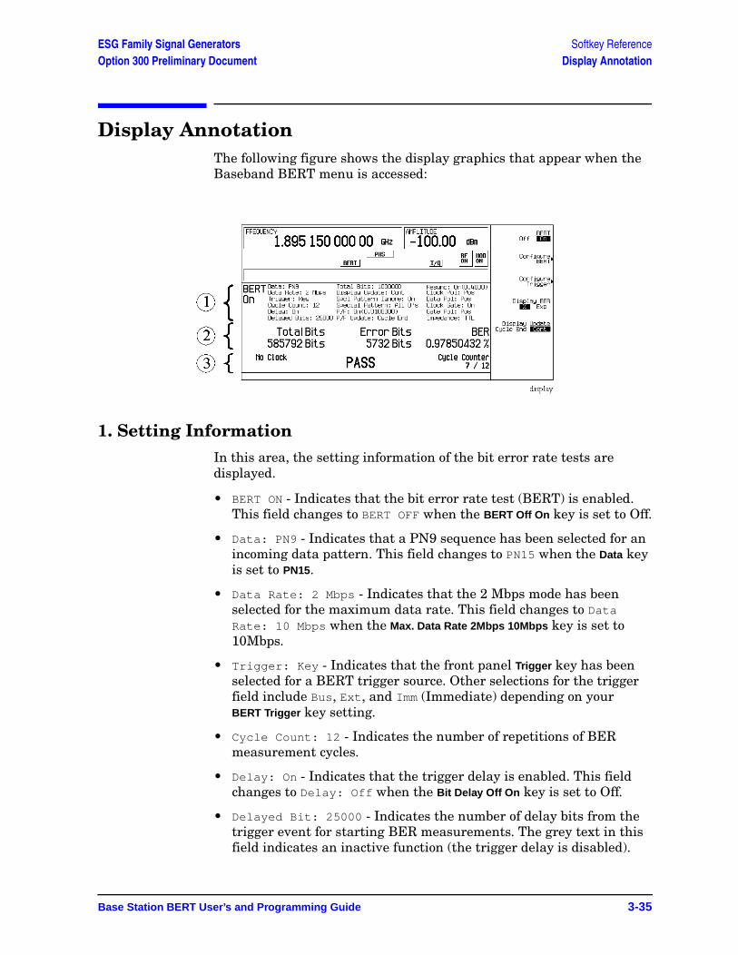
Base Station BERT User’s and Programming Guide 3-35
ESG Family Signal Generators Softkey ReferenceOption 300 Preliminary Document Display Annotation
Display AnnotationThe following figure shows the display graphics that appear when the Baseband BERT menu is accessed:
1. Setting InformationIn this area, the setting information of the bit error rate tests are displayed.
• BERT ON - Indicates that the bit error rate test (BERT) is enabled. This field changes to BERT OFF when the BERT Off On key is set to Off.
• Data: PN9 - Indicates that a PN9 sequence has been selected for an incoming data pattern. This field changes to PN15 when the Data key is set to PN15.
• Data Rate: 2 Mbps - Indicates that the 2 Mbps mode has been selected for the maximum data rate. This field changes to Data Rate: 10 Mbps when the Max. Data Rate 2Mbps 10Mbps key is set to 10Mbps.
• Trigger: Key - Indicates that the front panel Trigger key has been selected for a BERT trigger source. Other selections for the trigger field include Bus, Ext, and Imm (Immediate) depending on your BERT Trigger key setting.
• Cycle Count: 12 - Indicates the number of repetitions of BER measurement cycles.
• Delay: On - Indicates that the trigger delay is enabled. This field changes to Delay: Off when the Bit Delay Off On key is set to Off.
• Delayed Bit: 25000 - Indicates the number of delay bits from the trigger event for starting BER measurements. The grey text in this field indicates an inactive function (the trigger delay is disabled).
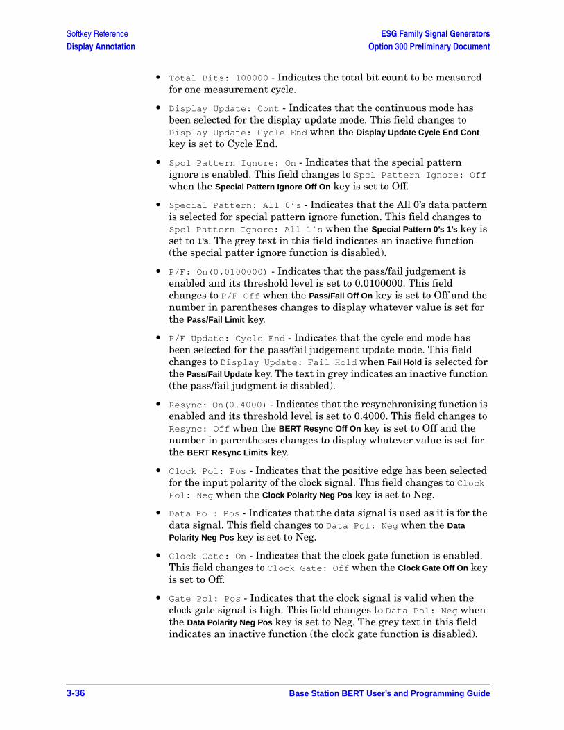
3-36 Base Station BERT User’s and Programming Guide
Softkey Reference ESG Family Signal GeneratorsDisplay Annotation Option 300 Preliminary Document
• Total Bits: 100000 - Indicates the total bit count to be measured for one measurement cycle.
• Display Update: Cont - Indicates that the continuous mode has been selected for the display update mode. This field changes to Display Update: Cycle End when the Display Update Cycle End Cont key is set to Cycle End.
• Spcl Pattern Ignore: On - Indicates that the special pattern ignore is enabled. This field changes to Spcl Pattern Ignore: Off when the Special Pattern Ignore Off On key is set to Off.
• Special Pattern: All 0’s - Indicates that the All 0’s data pattern is selected for special pattern ignore function. This field changes to Spcl Pattern Ignore: All 1’s when the Special Pattern 0’s 1’s key is set to 1’s. The grey text in this field indicates an inactive function (the special patter ignore function is disabled).
• P/F: On(0.0100000) - Indicates that the pass/fail judgement is enabled and its threshold level is set to 0.0100000. This field changes to P/F Off when the Pass/Fail Off On key is set to Off and the number in parentheses changes to display whatever value is set for the Pass/Fail Limit key.
• P/F Update: Cycle End - Indicates that the cycle end mode has been selected for the pass/fail judgement update mode. This field changes to Display Update: Fail Hold when Fail Hold is selected for the Pass/Fail Update key. The text in grey indicates an inactive function (the pass/fail judgment is disabled).
• Resync: On(0.4000) - Indicates that the resynchronizing function is enabled and its threshold level is set to 0.4000. This field changes to Resync: Off when the BERT Resync Off On key is set to Off and the number in parentheses changes to display whatever value is set for the BERT Resync Limits key.
• Clock Pol: Pos - Indicates that the positive edge has been selected for the input polarity of the clock signal. This field changes to Clock Pol: Neg when the Clock Polarity Neg Pos key is set to Neg.
• Data Pol: Pos - Indicates that the data signal is used as it is for the data signal. This field changes to Data Pol: Neg when the Data Polarity Neg Pos key is set to Neg.
• Clock Gate: On - Indicates that the clock gate function is enabled. This field changes to Clock Gate: Off when the Clock Gate Off On key is set to Off.
• Gate Pol: Pos - Indicates that the clock signal is valid when the clock gate signal is high. This field changes to Data Pol: Neg when the Data Polarity Neg Pos key is set to Neg. The grey text in this field indicates an inactive function (the clock gate function is disabled).

Base Station BERT User’s and Programming Guide 3-37
ESG Family Signal Generators Softkey ReferenceOption 300 Preliminary Document Display Annotation
• Impedance: TTL - Indicates that the TTL has been selected for the input termination mode. This field changes to Impedance: 75 Ohm when the Impedance 75 Ohm TTL key is set to 75 Ohm.
2. Measurement ResultsIn this area, the measurement results are displayed. When the Display Update Cycle End Cont key is set to Cycle End, the measurement result is displayed only when the one measurement cycle has been completed. When the Display Update Cycle End Cont key is set to Cont, the intermediate measurement result is also displayed about every 200 ms during the measurement cycle.
NOTE You can select Cont only when the Max. Data Rate 2Mbps 10Mbps key is set to 2Mbps.
• Total Bits: 585792 Bits - Shows the total bit count.
• Error Bits: 5732 Bits - Shows the error bit count.
• BER: 0.97850432 % - Shows the bit error rate measurement result. The BER measurement result can be displayed in percent or in the exponential format.
3. Other InformationIn this area, the measurement cycle counter is displayed on the right side. When the Pass/Fail Off On key is set to On, the result of the judgement is displayed in the center. The measurement error status may be displayed on the left side.
• No Data - In this field, No Data or No Clock may be displayed. No Data is displayed when there has been no data change for more than 200 clock signals. No Clock is displayed when there has been no clock input for more than 3 seconds.
Sync Loss may be displayed under the No Data annunciator when the synchronization is lost. (It is not shown in this example.)
• PASS - In this field, the pass/fail judgement result is displayed when the Pass/Fail Off On key is set to On.
• Cycle Counter: 7 / 12 - Indicates the current and total measurement cycle counts.
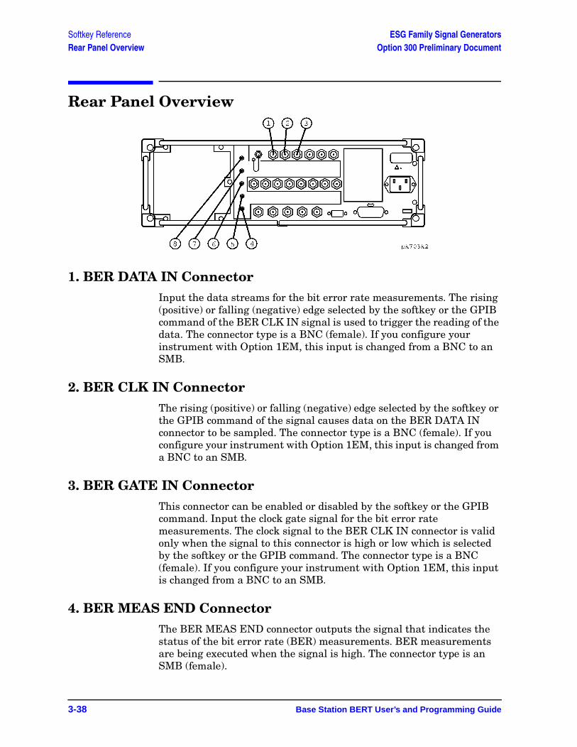
3-38 Base Station BERT User’s and Programming Guide
Softkey Reference ESG Family Signal GeneratorsRear Panel Overview Option 300 Preliminary Document
Rear Panel Overview
1. BER DATA IN ConnectorInput the data streams for the bit error rate measurements. The rising (positive) or falling (negative) edge selected by the softkey or the GPIB command of the BER CLK IN signal is used to trigger the reading of the data. The connector type is a BNC (female). If you configure your instrument with Option 1EM, this input is changed from a BNC to an SMB.
2. BER CLK IN ConnectorThe rising (positive) or falling (negative) edge selected by the softkey or the GPIB command of the signal causes data on the BER DATA IN connector to be sampled. The connector type is a BNC (female). If you configure your instrument with Option 1EM, this input is changed from a BNC to an SMB.
3. BER GATE IN ConnectorThis connector can be enabled or disabled by the softkey or the GPIB command. Input the clock gate signal for the bit error rate measurements. The clock signal to the BER CLK IN connector is valid only when the signal to this connector is high or low which is selected by the softkey or the GPIB command. The connector type is a BNC (female). If you configure your instrument with Option 1EM, this input is changed from a BNC to an SMB.
4. BER MEAS END ConnectorThe BER MEAS END connector outputs the signal that indicates the status of the bit error rate (BER) measurements. BER measurements are being executed when the signal is high. The connector type is an SMB (female).
Base Station BERT User’s and Programming Guide 3-39
ESG Family Signal Generators Softkey ReferenceOption 300 Preliminary Document Rear Panel Overview
5. BER TEST OUT ConnectorThe BER TEST OUT connector outputs the signal that indicates the test result of the pass/fail judgment of the bit error rate measurements. The result is guaranteed at the falling edge of the signal of the MEAS END connector. The result is pass when the signal is low; the result is fail when the signal is high. The signal is also high when the pass/fail judgment is set to off. The connector type is an SMB (female).
6. BER ERR OUT ConnectorThe output of the BER ERR OUT connector is normally low. When the maximum data rate mode is set to 2 Mbps, the BER ERR OUT connector outputs the pulse signals that indicate the number of the error bits. One pulse whose width is about 80 ns indicates one error bit. Pulses for the error bits of one measurement cycle are not synchronized with the clock signal to the BER CLK IN connector, and are output during the signal of the BER MEAS END connector for the measurement cycle is high. The connector type is an SMB (female).
7. BER NO DATA ConnectorThe BER NO DATA connector outputs the signal that indicates the no data status. The no data status is reported when there has been no clock inputs for more than 3 seconds or there has been no data change for more than 200 bits. This signal is valid only when the signal of the BER MEAS END connector is high. No data status is detected when the signal is low. The connector type is an SMB (female).
8. BER SYNC LOSS ConnectorThe BER SYNC LOSS connector outputs the signal that indicates the synchronization loss state. This signal is only valid when the signal of the BER MEAS END connector is high. Synchronization loss state is detected when the signal is low. The connector type is an SMB (female).

3-40 Base Station BERT User’s and Programming Guide
Softkey Reference ESG Family Signal GeneratorsRear Panel Overview Option 300 Preliminary Document
GSM Base Station Test User’s and Programming Guide 4-1
ESG Family Signal GeneratorsOption 300 Preliminary Document
4 Remote Programming
This chapter contains the Option 300 Standard Commands for Programmable Instruments (SCPI) commands. A description of each command is provided as well as syntax requirements, ranges, restrictions, query responses, and status at *RST. Refer to Option UN8 and Option 202 user’s and programming guide for commands not found.
For information regarding SCPI common terms, queries, implied commands, command strings, and command syntax, refer to the main programming guide.
Remote Programming ESG Family Signal GeneratorsOption 300 SCPI Command Reference Option 300 Preliminary Document
4-2 GSM Base Station Test User’s and Programming Guide
Option 300 SCPI Command ReferenceThe following SCPI commands are used to set the controls and the parameters associated with Option 300 functionality.
BER Clock Gate Polarity:INPut:BERT[:Baseband]:CGATe:POLarity POSitive|NEGative:INPut:BERT[:Baseband]:CGATe:POLarity?
This command selects the clock gate polarity. The choices are POSitive and NEGative. This clock gate signal is supplied to the rear panel BER GATE IN port. This command is valid only while the BER clock gate state is ON (1).
*RST value: POSitive
BER Clock Gate State:INPut:BERT[:Baseband]:CGATe[:STATe] ON|OFF|1|0:INPut:BERT[:Baseband]:CGATe[:STATe]?
This command enables and disables the clock gate function. The choices are ON (1) and OFF (0).
*RST value: OFF
BER Clock Polarity:INPut:BERT[:Baseband]:CLOCk:POLarity POSitive|NEGative:INPut:BERT[:Baseband]:CLOCk:POLarity?
This command selects the clock polarity according to the clock signal supplied to the rear panel BER CLK IN port. The choices are POSitive and NEGative.
*RST value: POSitive
BER Cycle Count:SENSe:BERT[:Baseband]:TRIGger:COUNt <num>:SENSe:BERT[:Baseband]:TRIGger:COUNt?
This command specifies the repeat times of BER measurements.
Range: 1 to 65535
*RST value: 1
ESG Family Signal Generators Remote ProgrammingOption 300 Option 300 SCPI Command Reference
GSM Base Station Test User’s and Programming Guide 4-3
BER Data Pattern:SENSe:BERT[:Baseband]:PRBS[:DATA] PN9|PN15:SENSe:BERT[:Baseband]:PRBS[:DATA]?
This command selects the data pattern for the incoming data bit stream to make BER measurements. The choices are PN9 and PN15.
*RST value: PN9
BER Data Polarity:INPut:BERT[:Baseband]:DATA:POLarity POSitive|NEGative:INPut:BERT[:Baseband]:DATA:POLarity?
This command selects the polarity of the data signal. The choices are POSitive and NEGative.
*RST value: POSitive
BER Display Mode:CALCulate:BERT[:Baseband]:DISPlay:MODE PERCent|SCIentific:CALCulate:BERT[:Baseband]:DISPlay:MODE?
This command selects the display mode for bit error rate measurement results. The choices are PERCent and SCIentific. When you select PERCent, BER measurement results are displayed in %. When you select SCIentific, BER measurement results are displayed in the following format: n.nnnnnE-mm (where n.nnnnn is a floating point part and E-mm is a power exponent part).
*RST value: PERcent
BER Display Update Mode:CALCulate:BERT[:Baseband]:DISPlay:UPDate CEND|CONT:CALCulate:BERT[:Baseband]:DISPlay:UPDate?
This command selects the display update mode during BER measurements. The choices are CEND (Cycle End) and CONT (Continuous). When you select CEND, the previous BER measurement result is displayed during the current measuring period. When you select CONT, the display shows its real-time intermediate results during each BER measurement.
*RST value: CEND
BER Input Impedance:INPut:BERT[:Baseband]:IMPedance TTL|OHM_75:INPut:BERT[:Baseband]:IMPedance?
This command selects the input impedance according to the input signals supplied to the rear panel BER DATA IN, BER CLK IN, and BER GATE IN ports. The choices are OHM_75 (75Ω) and TTL.
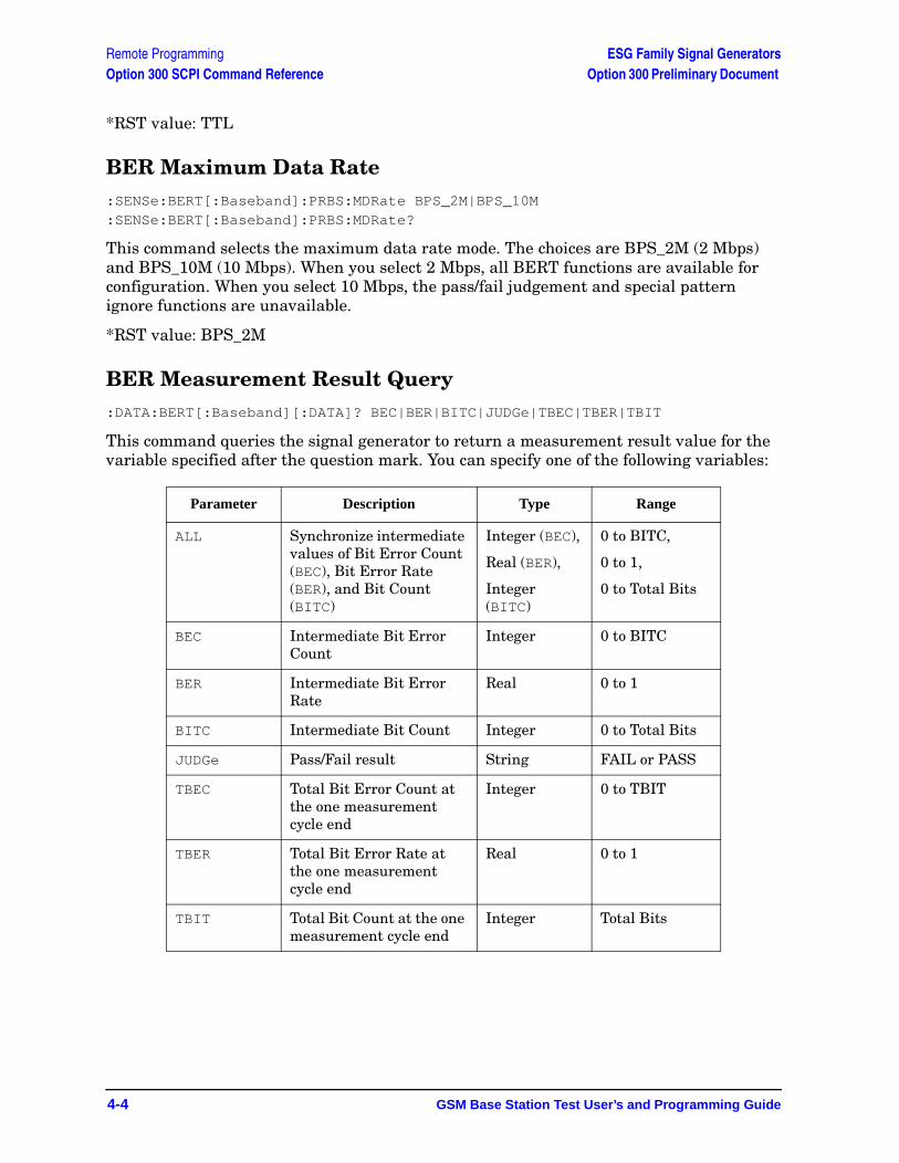
Remote Programming ESG Family Signal GeneratorsOption 300 SCPI Command Reference Option 300 Preliminary Document
4-4 GSM Base Station Test User’s and Programming Guide
*RST value: TTL
BER Maximum Data Rate:SENSe:BERT[:Baseband]:PRBS:MDRate BPS_2M|BPS_10M:SENSe:BERT[:Baseband]:PRBS:MDRate?
This command selects the maximum data rate mode. The choices are BPS_2M (2 Mbps) and BPS_10M (10 Mbps). When you select 2 Mbps, all BERT functions are available for configuration. When you select 10 Mbps, the pass/fail judgement and special pattern ignore functions are unavailable.
*RST value: BPS_2M
BER Measurement Result Query:DATA:BERT[:Baseband][:DATA]? BEC|BER|BITC|JUDGe|TBEC|TBER|TBIT
This command queries the signal generator to return a measurement result value for the variable specified after the question mark. You can specify one of the following variables:
Parameter Description Type Range
ALL Synchronize intermediate values of Bit Error Count (BEC), Bit Error Rate (BER), and Bit Count (BITC)
Integer (BEC),
Real (BER),
Integer (BITC)
0 to BITC,
0 to 1,
0 to Total Bits
BEC Intermediate Bit Error Count
Integer 0 to BITC
BER Intermediate Bit Error Rate
Real 0 to 1
BITC Intermediate Bit Count Integer 0 to Total Bits
JUDGe Pass/Fail result String FAIL or PASS
TBEC Total Bit Error Count at the one measurement cycle end
Integer 0 to TBIT
TBER Total Bit Error Rate at the one measurement cycle end
Real 0 to 1
TBIT Total Bit Count at the one measurement cycle end
Integer Total Bits
ESG Family Signal Generators Remote ProgrammingOption 300 Option 300 SCPI Command Reference
GSM Base Station Test User’s and Programming Guide 4-5
BER Pass/Fail Judgement Mode:CALCulate:BERT[:Baseband]:COMParator:MODE CEND|FHOLd:CALCulate:BERT[:Baseband]:COMParator:MODE?
This command selects the pass/fail judgement mode of the comparator function. The choices are CEND (Cycle End) and FHOLd (Fail Hold). When you select CEND, each BER measurement result is compared with the Pass/Fail Limit value and judged to make a pass/fail test. When you select FHOLd, only one fail judgement is made once a fail has been found during that BER measurement loop. For automated tests, use the output signal from the rear panel BER TEST OUT port.
*RST value: CEND
BER Pass/Fail Limits:CALCulate:BERT[:Baseband]:COMParator:THReshold <num>:CALCulate:BERT[:Baseband]:COMParator:THReshold?
This command specifies the threshold value for the pass/fail judgement function. This command is valid only while the BER pass/fail state command is ON (1).
Range: 0 to 1
*RST value: 0.5
BER Pass/Fail State:CALCulate:BERT[:Baseband]:COMParator[:STATe] ON|OFF|1|0:CALCulate:BERT[:Baseband]:COMParator[:STATe]?
This command enables and disables the pass/fail judgement function. The choices are ON (1) and OFF (0). For automated tests, use the output signal from the rear panel BER TEST OUT port.
*RST value: OFF
BER Resync Limits:SENSe:BERT[:Baseband]:RSYNc:THReshold <num>:SENSe:BERT[:Baseband]:RSYNc:THReshold?
This command specifies the threshold level for the resynchronizing function. This function is valid only when BERT resynchronization state is set to ON.
Range: 0.05 to 0.40
*RST value: 0.40
Remote Programming ESG Family Signal GeneratorsOption 300 SCPI Command Reference Option 300 Preliminary Document
4-6 GSM Base Station Test User’s and Programming Guide
BER Resynchronization State:SENSe:BERT[:Baseband]:RSYNc[:STATe] ON|OFF|1|0:SENSe:BERT[:Baseband]:RSYNc[:STATe]?
This command enables and disables the resynchronization function. The choices are ON (1) and OFF (0). This function is valid only when the maximum data rate is set to 2 Mbps.
*RST value: ON
BER Special Pattern Ignore Data:SENSe:BERT[:Baseband]:PRBS:FUNCtion:SPIGnore:DATA ALL_0|ALL_1:SENSe:BERT[:Baseband]:PRBS:FUNCtion:SPIGnore:DATA?
This command selects the bit parameter of the special pattern ignore function. The choices are ALL_0 (All 0’s) and ALL_1 (All 1’s). This command is valid only when Special Pattern Ignore state is already set to ON.
*RST value: ALL_0
BER Special Pattern Ignore State:SENSe:BERT[:Baseband]:PRBS:FUNCtion:SPIGnore[:STATe] ON|OFF|1|0:SENSe:BERT[:Baseband]:PRBS:FUNCtion:SPIGnore[:STATe]?
This command enables and disables the operating state of the special pattern ignore function. The choices are ON (1) and OFF (0). This function detects more than 80 bits of 0's or 1's in the incoming bit stream and ignores these bits when making BER measurements. This command is valid only when the maximum data rate is set to 2 Mbps.
*RST value: OFF
BER Total Bits:SENSe:BERT[:Baseband]:TBITs <num>:SENSe:BERT[:Baseband]:TBITs?
This command specifies the total bit count to be measured.
Range: 100 to 4294967295
*RST value: 10000
BER Trigger Bit Delay:SENSe:BERT[:Baseband]:TRIGger:BDELay <num>:SENSe:BERT[:Baseband]:TRIGger:BDELay?
This command specifies the number of delay bits for the trigger delay. This function is valid only when the trigger bit delay state is set to ON.
Range: 0 to 65535
*RST value: 0
ESG Family Signal Generators Remote ProgrammingOption 300 Option 300 SCPI Command Reference
GSM Base Station Test User’s and Programming Guide 4-7
BER Trigger Bit Delay State:SENSe:BERT[:Baseband]:TRIGger:BDELay:STATe ON|OFF|1|0:SENSe:BERT[:Baseband]:TRIGger:BDELay:STATe?
This command enables and disables the trigger bit delay function. The choices are ON (1) and OFF (0).
*RST value: OFF
BER Trigger Source:SENSe:BERT[:Baseband]:TRIGger[:SOURce] IMMediate|KEY|EXT|BUS:SENSe:BERT[:Baseband]:TRIGger[:SOURce]?
This command selects the triggering type for starting BER measurements. The choices are BUS (trigger with a *TRG GPIB command), EXTernal (trigger with an external signal supplied to the rear panel TRIGGER IN connector), IMMediate, and KEY (trigger using the front panel Trigger key).
*RST value: KEY
BERT State:SENSe:BERT[:Baseband]:STATe ON|OFF|1|0:SENSe:BERT[:Baseband]:STATe?
This command enables and disables the BER measurement function. The choices are ON (1) or OFF (0).
*RST value: OFF
BERT Trigger Source Selection
EDGE
:SENSe:BERT:BTS:LOOPback:EDGE:TRIGger[:SOURce] IMMediate|KEY|EXT|BUS
:SENSe:BERT:BTS:LOOPback:EDGE:TRIGger[:SOURce]?
GSM
:SENSe:BERT:BTS:LOOPback:GSM:TRIGger[:SOURce] IMMediate|KEY|EXT|BUS:SENSe:BERT:BTS:LOOPback:GSM:TRIGger[:SOURce]?
This command determines the trigger source for the GSM or EDGE loopback bit error rate measurement.
• Select IMMediate to begin the measurement directly after synchronization has been achieved.
• Select KEY to begin the measurement when the front panel Trigger key is pressed, provided that synchronization has been achieved. If synchronization has not occurred, the trigger is ignored.
Remote Programming ESG Family Signal GeneratorsOption 300 SCPI Command Reference Option 300 Preliminary Document
4-8 GSM Base Station Test User’s and Programming Guide
• Select EXT to begin the measurement as soon as a trigger signal is applied to the TRIGGER IN rear panel connector provided that synchronization has been achieved. If synchronization has not occurred, the trigger is ignored.
• Select BUS to begin the measurement once a GPIB trigger command is received by the signal generator provided that synchronization has been achieved. If synchronization has not occurred, the trigger is ignored.
An inherent variable delay will always exist when starting a measurement because the measurement must await the start of the next speech frame after the trigger. The delay can vary between 0 and 23 ms (5 frames) depending on where the trigger falls within the TDMA multiframe.
A trigger is ignored unless the GSM or EDGE loopback operating state is turned on.
*RST value: KEY
Bit Count:SENSe:BERT:BTS:LOOPback:EDGE:UNCoded:BIT:COUNt <value> :SENSe:BERT:BTS:LOOPback:EDGE:UNCoded:BIT:COUNt?
This command specifies the total number of bits to be measured for the uncoded channel.
Range: 1 to 2147483647
*RST value: 139200
BLER Measurement:SENSe:BERT:BTS:LOOPback:EDGE:MCS5:CONTain ON|OFF|1|0 :SENSe:BERT:BTS:LOOPback:EDGE:MCS5:CONTain?
:SENSe:BERT:BTS:LOOPback:EDGE:MCS9:BLOCk:CONTain ON|OFF|1|0 :SENSe:BERT:BTS:LOOPback:EDGE:MCS9:BLOCk:CONTain?
:SENSe:BERT:BTS:LOOPback:EDGE:ETCH:F43:BLOCk:CONTain ON|OFF|1|0 :SENSe:BERT:BTS:LOOPback:EDGE:ETCH:F43:BLOCk:CONTain?
This command enables or disables the BER measurement for MCS-5, and MCS-9 channels in addition to the BLER measurement. When enabled, the following results can also be returned from the measurement:
• Number of non-erased blocks that contain bit errors.
• Percentage of non-erased blocks that contain bit errors.
• Average BER of total error bit counts within non-erased blocks that contain bit errors.

ESG Family Signal Generators Remote ProgrammingOption 300 Option 300 SCPI Command Reference
GSM Base Station Test User’s and Programming Guide 4-9
Block Count:SENSe:BERT:BTS:LOOPback:EDGE:MCS5:BLOCk:COUNt <value> :SENSe:BERT:BTS:LOOPback:EDGE:MCS5:BLOCk:COUNt?
:SENSe:BERT:BTS:LOOPback:EDGE:MCS9:BLOCk:COUNt <value> :SENSe:BERT:BTS:LOOPback:EDGE:MCS9:BLOCk:COUNt?
This command specifies the total number of blocks to be measured. If an out of range value is entered, it will be rounded to either the minimum or maximum value.
For MCS9, only even values can be entered. If an odd number is entered, a +1 will automatically be added to make the value even.
Range: 1 to 1500000
*RST value: 600
Class Ib Bits, Number to be Measured:SENSe:BERT:BTS:LOOPback:GSM:FRAMe:CIB?
This query returns the total number of Class Ib bits to be measured which are calculated from the total number of frames specified to be measured.
Range: 132 to 792000000
*RST value: 13200
Class II Bits, Number to be Measured:SENSe:BERT:BTS:LOOPback:GSM:FRAMe:CII?
This query returns the total number of Class II bits to be measured which are calculated from the total number of frames specified to be measured.
Range: 78 to 468000000
*RST value: 7800
Data
EDGE
:DATA:BERT:BTS:LOOPback:EDGE:MCS5[:DATA]? IEC|IEBC|DEFC|BCO|IER|IABer|ALL|TEC|TEBC|TDEFc|TBCO|TER|TABer|TALL|JUDGe|STOP|SCAuse
:DATA:BERT:BTS:LOOPback:EDGE:MCS9[:DATA]? IEC|IEBC|DEFC|BCO|IER|IABer|ALL|TEC|TEBC|TDEFc|TBCO|TER|TABer|TALL|JUDGe|STOP|SCAuse
:DATA:BERT:BTS:LOOPback:EDGE:UNCoded[:DATA]? IEC|IEBC|DEFC|BCO|IER|IABer|ALL|TEC|TEBC|TDEFc|TBCO|TER|TABer|TALL|JUDGe|STOP|SCAuse
This data query returns the measurement result value for each variable.
IEC|IEBC|DEFC|BCO|IER|IABer return intermediate values. During the measurement,
Remote Programming ESG Family Signal GeneratorsOption 300 SCPI Command Reference Option 300 Preliminary Document
4-10 GSM Base Station Test User’s and Programming Guide
these variables are updated as well as the display information. ALL returns all intermediate values at the same time.
At the end of the measurement, the final values are stored to: TEC|TEBC|TDEFc|TBCO|TER|TABer variables. These variables and JUDGe|STOP|SCAuse are not updated until the next BER measurement is completed. TALL returns all of the total values at the same time.
IEC: intermediate error count <Integer> 0 to 1500000
IEBC: intermediate non-erased bit error blocks <Integer> 0 to 2147483647
DEFC: intermediate downlink error frame count <Integer> 0 to 750000
BCO: intermediate block or bit count <Integer> 0 to 1500000<Integer> 0 to 2147483647 for Uncoded channel
IER: intermediate error ratio <Real> 0 to 1 (0 to 100%)
IABer: intermediate average BER within blocks that have errors <Real> 0 to 1
ALL: IEC IEBC DEFC BCO IER IABer
TEC: total error count <Integer> 0 to 1500000<Integer> 0 to 2147483647 for Uncoded channel
TEBC: total non-erased bit error blocks<Integer> 0 to 1500000
TDEFc: total downlink error frame count <Integer> 0 to 65,535
TBCO: total block <Integer> 0 to 1500000,<Integer> 0 to 2147483647 for Uncoded channel
TER: total error ratio <Real> 0 to 1 (0 to 100%)
TABer: total average BER within blocks that have errors <Real> 0 to 1
TALL: TEC TEBC TDEFc TBCO TER TABer JUDGe JCAuse STOP SCAUseIf accidental TCH synchronization loss caused the measurement to stop, TSLoss is returned.
JUDGe: comparator result (TEST OUT) <Enumerated set> FAIL PASS NONEIf Pass/Fail criteria is NOLimit, NONE is returned.
STOP: if stop threshold is met? <Enumerated set> TRUE FALSEWhen threshold to stop criteria is NONE, FALSE is returned.
SCAuse: stop cause <Enumerated set> NONE Ebit EBLock TSLIf accidental TCH synchronization loss caused the measurement to stop, TSL is returned.
GSM
:DATA:BERT:BTS:LOOPback:GSM[:DATA]? IBC|IIC|FEC|DEFC|FRC|IBBer|IIBer|FER|ALL|TIBC|TIIC|TFEC|TDEFc|TFRC|TIBBer|TIIBer|TFER|JUDGe|JCAuse|STOP|SCAuse|TALL
This data query returns the measurement result value for each variable.
IBC|IIC|FEC|DEFC|FRC|IBBer|IIBer|FER are intermediate values, so during the
ESG Family Signal Generators Remote ProgrammingOption 300 Option 300 SCPI Command Reference
GSM Base Station Test User’s and Programming Guide 4-11
measurement, these variables are updated as well as the display information. ALL returns intermediate values at the same time.
At the end of the measurement, the final values are stored to: TIBC|TIIC|TFEC|TDEFc|TFRC|TIBBer|TIIBer|TFER variables. These variables and JUDGe|JCAuse|STOP|SCAuse are not updated until the next BER measurement is completed. TALL returns all of the total values at the same time.
IBC: intermediate class Ib error count <Integer> 0 to 792000000
IIC: intermediate class II error count <Integer> 0 to 468000000
FEC: intermediate frame erasure count <Integer> 0 to 6000000
DEFC: intermediate downlink error frame count <Integer> 0 to 65535
FRC: intermediate frame count <Integer> 0 to 6000000
IBBer: intermediate class Ib error ratio <Real> 0 to 1 (0 to 100%)
IIBer: intermediate class II error ratio <Real> 0 to 1 (0 to 100%)
FER: intermediate frame erasure ratio <Real> 0 to 1 (0 to 100%)
ALL: IBC IIC FEC DEFC FRC IBBer IIBer FER
TIBC: total class Ib bit error count <Integer> 0 to 792000000
TIIC: total class II bit error count <Integer> 0 to 468000000
TFEC: total frame erasure count <Integer> 0 to 6000000
TDEFc: total downlink error frame count <Integer> 0 to 65535
TFRC: total frame count <Integer> 0 to 6000000
TIBBer: total class Ib error ratio <Real> 0 to 1 (0 to 100%)
TIIBer: total class II error ratio <Real> 0 to 1 (0 to 100%)
TFER: total frame erasure ratio <Real> 0 to 1 (0 to 100%)
TALL: TIBC TIIC TFEC TDEFc TFRC TIBBer TIIBer TFER JUDGe JCAuse STOP SCAUseIf accidental TCH synchronization loss caused the measurement to stop, TSLoss is returned.
JUDGe: comparator result (TEST OUT) <Enumerated set> FAIL PASS NONEIf Pass/Fail criteria is NOLimit, NONE is returned.
JCAuse: which limit was met to cause the comparator result.<Enumerated set> NOLimit FER CIB CII
STOP: if stop threshold is met? <Enumerated set> TRUE FALSEWhen threshold to stop criteria is NONE, FALSE is returned.
SCAuse: stop cause <Enumerated set> NONE FE CIB CII TSLossIf accidental TCH synchronization loss caused the measurement to stop, TSLoss is returned.
Remote Programming ESG Family Signal GeneratorsOption 300 SCPI Command Reference Option 300 Preliminary Document
4-12 GSM Base Station Test User’s and Programming Guide
External Frame Trigger Delay:SENSe:BERT:BTS:LOOPback:EDGE:FTRigger:EXTernal:DELay <numaric_value>:SENSe:BERT:BTS:LOOPback:EDGE:FTRigger:EXTernal:DELay?
This command sets the external frame trigger delay for the EDGE loopback bit error rate measurement.
Range: −1250.0 through 1250.0 symbols
*RST value: POSitive
External Frame Trigger Polarity:SENSe:BERT:BTS:LOOPback:EDGE:FTRigger:EXTernal:POLarity POSitive|NEGative:SENSe:BERT:BTS:LOOPback:EDGE:FTRigger:EXTernal:POLarity?
This command sets the external frame trigger polarity for the EDGE loopback bit error rate measurement.
*RST value: POSitive
Frame Count (BER %):SENSe:BERT:BTS:LOOPback:GSM:FRAMe:COUNt <numeric_value>:SENSe:BERT:BTS:LOOPback:GSM:FRAMe:COUNt?
This command determines the length of the measurement specified by the total number of frames included in one measurement.
Range: 1 to 6000000
*RST value: 100
Frame Trigger Source:SENSe:BERT:BTS:LOOPback:EDGE:FTRigger[:SELect] INTernal|EXTernal :SENSe:BERT:BTS:LOOPback:EDGE:FTRigger[:SELect]?
This command sets the frame trigger source for the EDGE loopback bit error rate measurement.
*RST value: INTernal
Frame Synchronization Source
EDGE
:SENSe:BERT:BTS:LOOPback:EDGE:SYNC[:SOURce] BCH|PDCH :SENSe:BERT:BTS:LOOPback:EDGE:SYNC[:SOURce]?
This command specifies the synchronization source from the BTS under test. The choices are BCH or PDCH.
*RST value: BCH
ESG Family Signal Generators Remote ProgrammingOption 300 Option 300 SCPI Command Reference
GSM Base Station Test User’s and Programming Guide 4-13
Loopback Operating State
EDGE
:SENSe:BERT:BTS:LOOPback:EDGE[:STATe] ON|OFF|1|0:SENSe:BERT:BTS:LOOPback:EDGE[:STATe]?
This command turns on and off the operating state of the EDGE loopback bit error rate function. Although you can configure the measurement parameters while the operating state is off, any command triggers sent will be ignored until the operating state is turned on.
NOTE The following message will appear if the amplitude level is incorrect when you turn EDGE BERT on:
522 “Demodulator Unleveled; Input amplitude underrange.”
*RST value: OFF

Remote Programming ESG Family Signal GeneratorsOption 300 SCPI Command Reference Option 300 Preliminary Document
4-14 GSM Base Station Test User’s and Programming Guide
GSM
:SENSe:BERT:BTS:LOOPback:GSM[:STATe] ON|OFF|1|0:SENSe:BERT:BTS:LOOPback:GSM[:STATe]?
This command turns on and off the operating state of the GSM loopback bit error rate function. Although you can configure the measurement parameters while the operating state is off, any command triggers sent will be ignored until the operating state is turned on.
NOTE The following message will appear if the amplitude level is incorrect when you turn GSM BERT on:
522 “Demodulator Unleveled; Input amplitude underrange.”
*RST value: OFF
Measurement Mode, Switching
EDGE
:SENSe:BERT:BTS:LOOPback:EDGE:MEASurement[:MODE] BLER|SSEarch:SENSe:BERT:BTS:LOOPback:EDGE:MEASurement[:MODE]?
This command changes the measurement mode between BLER% and sensitivity search. This also changes the EDGE BERT display and enables the Configuration menu for either the BER% Configure menu or the sensitivity search menu. If the BLER% measurement is already running, this command will abort the BLER% measurement. If Sensitivity Search is initiated from remote control, the BUS trigger is disallowed. If sensitivity search is initiated from the front panel, the BUS trigger is allowed.
*RST value: BLER
GSM
:SENSe:BERT:BTS:LOOPback:GSM:MEASurement[:MODE] BER|SSEarch:SENSe:BERT:BTS:LOOPback:GSM:MEASurement[:MODE]?
This command changes the measurement mode between BER% and sensitivity search. This also changes the GSM BERT display and enables the Configuration menu for either the BER% Configure menu or the Sensitivity Search menu. If the BER% measurement is already running, this command will abort the BER% measurement. If sensitivity search is initiated from remote control, the BUS trigger is disallowed. If sensitivity search is initiated from the front panel, the BUS trigger is allowed.
*RST value: BER
Measurement Sensitivity
EDGE
:MEASure[:SCALAR]:BERT:BTS:LOOPback:EDGE:MCS5[:SENSitivity]?:MEASure[:SCALAR]:BERT:BTS:LOOPback:EDGE:MCS9[:SENSitivity]?
ESG Family Signal Generators Remote ProgrammingOption 300 Option 300 SCPI Command Reference
GSM Base Station Test User’s and Programming Guide 4-15
:MEASure[:SCALAR]:BERT:BTS:LOOPback:EDGE:UNCoded[:SENSitivity]?
This query returns either PASS or FAIL and the result for the measured sensitivity level. The trigger source must be set to IMMediate to execute this command. When this command is executed before the signal generator is synchronized with the BTS, the message “Fail, −999.00” is displayed.
There are two other status errors that may be returned; SERR or DERR.
SERR RF synchronization is lost during search and the search is aborted
DERR a downlink error occurred during search and the search is aborted
When these errors are returned, the sensitivity search returns a value of −1.0.
This command can be used in both the BER% measurement or the sensitivity search mode. If the trigger source selection is BUS, error “-214 Trigger deadlock” is generated and no data is returned. After this command is executed, the measurement mode is in the sensitivity search mode.
GSM
:MEASure[:SCALAR]:BERT:BTS:LOOPback:GSM[:SENSitivity]?
This query returns either PASS or FAIL and the result for the measured sensitivity level. The trigger source must be set to IMMediate to execute this command. When this command is executed before the signal generator is synchronized with the BTS, the message“Fail, −999.00” is displayed.
There are two other status errors that may be returned; SERR or DERR.
SERR RF synchronization is lost during search and the search is aborted
DERR a downlink error occurred during search and the search is aborted
When these errors are returned, the sensitivity search returns a value of −1.0.
This command can be used in both the BER% measurement or the sensitivity search mode. If the trigger source selection is BUS, error “-214 Trigger deadlock” is generated and no data is returned. After this command is executed, the measurement mode is in the sensitivity search mode.
Measurement, Stopping
EDGE
:SENSe:BERT:BTS:LOOPback:EDGE:MEASurement:STOP
This command immediately stops any current measurement and releases the PRBS synchronization. After the synchronization is released, a new PRBS synchronization is attempted.
GSM
:SENSe:BERT:BTS:LOOPback:GSM:MEASurement:STOP

Remote Programming ESG Family Signal GeneratorsOption 300 SCPI Command Reference Option 300 Preliminary Document
4-16 GSM Base Station Test User’s and Programming Guide
This command stops any current measurement and releases the current PRBS synchronization. After the synchronization is released, a new PRBS synchronization is attempted.
Pass/Fail Limit, Class Ib RBER:CALCulate:BERT:BTS:LOOPback:GSM:COMParator:CRITeria:CIB <numeric_value>:CALCulate:BERT:BTS:LOOPback:GSM:COMParator:CRITeria:CIB?
This command sets the pass/fail threshold value for Class II residual bit error rate.
Range: 0 to 1 (0% to 100%)
*RST value: 0.004
Pass/Fail Limit, Class II RBER:CALCulate:BERT:COMParator[:CRITeria]:CII <numeric_value>:CALCulate:BERT:COMParator[:CRITeria]:CII?
This command sets the pass/fail threshold value for Class Ib residual bit error rate.
Range: 0 to 1 (0% to 100%)
*RST value: 0.020 (2.0000%).
Pass/Fail Limit, Error Rate:CALCulate:BERT:BTS:LOOPback:EDGE:MCS5:COMParator:CRITeria:ERATe <numeric_value>:CALCulate:BERT:BTS:LOOPback:EDGE:MCS5:COMParator:CRITeria:ERATe?
:CALCulate:BERT:BTS:LOOPback:EDGE:MCS9:COMParator:CRITeria:ERATe <numeric_value>:CALCulate:BERT:BTS:LOOPback:EDGE:MCS9:COMParator:CRITeria:ERATe?
:CALCulate:BERT:BTS:LOOPback:EDGE:UNCoded:COMParator:CRITeria:ERATe <numeric_value>:CALCulate:BERT:BTS:LOOPback:EDGE:UNCoded:COMParator:CRITeria:ERATe?
This command sets the pass/fail threshold value for error rate. If an out-of-range value is set, the value will be rounded to either the minimum or maximum limit value.
Range: 0 to 1500000 for MCS5, MCS90 to 2147483647 for Uncoded channel
*RST value: 0.1 MCS5, MCS90.02 Uncoded
Pass/Fail Limit, Frame Erasure Ratio:CALCulate:BERT:BTS:LOOPback:GSM:COMParator:CRITeria:FERasure <numeric_value>:CALCulate:BERT:BTS:LOOPback:GSM:COMParator:CRITeria:FERasure?
ESG Family Signal Generators Remote ProgrammingOption 300 Option 300 SCPI Command Reference
GSM Base Station Test User’s and Programming Guide 4-17
This command sets the pass/fail threshold value for frame erasure rate.
Range: 0 to 1 (0% to 100%).
*RST value: 0.001 (0.1000%).
Pass/Fail Limit, Selection
EDGE
:CALCulate:BERT:BTS:LOOPback:EDGE:MCS5:COMParator:CRITeria[:SELect] ERATe|NOLimit:CALCulate:BERT:BTS:LOOPback:EDGE:MCS5:COMParator:CRITeria[SELect]?
:CALCulate:BERT:BTS:LOOPback:EDGE:MCS9:COMParator:CRITeria[:SELect] ERATe|NOLimit:CALCulate:BERT:BTS:LOOPback:EDGE:MCS9:COMParator:CRITeria[SELect]?
:CALCulate:BERT:BTS:LOOPback:EDGE:UNCoded:COMParator:CRITeria[:SELect] EBIT|NOLimit:CALCulate:BERT:BTS:LOOPback:EDGE:UNCoded:COMParator:CRITeria[SELect]?
This command determines which of the following pass/fail limit (comparator) criteria is applied to the measurement.
• Select ERATe to report the pass or fail status compared to the specified threshold for error rate.
• Select NOLimit to disable the pass/fail indication.
*RST value: NOLimit
GSM
:CALCulate:BERT:BTS:LOOPback:GSM:COMParator:CRITeria[:SELect] FERasure|CIB|CII|ANY|NOLimit:CALCulate:BERT:BTS:LOOPback:GSM:COMParator:CRITeria[SELect]?
This command determines which of the following pass/fail limit (comparator) criteria is applied to the measurement.
• Select FERasure to report the pass or fail status compared to the specified threshold for frame erasure ratio.
• Select CIB to report the pass or fail status compared to the specified threshold for the number of Class Ib errors detected in the measurement.
• Select CII to report the pass or fail status compared to the specified threshold for the number of Class II errors detected in the measurement.
• Select ANY to report the pass or fail status compared to all of the specified comparator criteria.
• Select NOLimit to disable the pass/fail indication.
*RST value: NOLimit
Remote Programming ESG Family Signal GeneratorsOption 300 SCPI Command Reference Option 300 Preliminary Document
4-18 GSM Base Station Test User’s and Programming Guide
Sensitivity Search, Bit Count:SENSe:BERT:BTS:LOOPback:EDGE:UNCoded:SBIT:COUNt <value> :SENSe:BERT:BTS:LOOPback:EDGE:UNCoded:SBIT:COUNt?
This command specifies the total number of bits to be measured during sensitivity search for the uncoded channel.
Range: 13920 to 2147483647
*RST value: 13920
Sensitivity Search, Block Count:SENSe:BERT:BTS:LOOPback:EDGE:MCS5:SBLOck:COUNt <numeric_value>:SENSe:BERT:BTS:LOOPback:EDGE:MCS5:SBLOck:COUNt?
:SENSe:BERT:BTS:LOOPback:EDGE:MCS9:SBLOck:COUNt <numeric_value>:SENSe:BERT:BTS:LOOPback:EDGE:MCS9:SBLOck:COUNt?
This command specifies the total number of blocks to be measured at each measurement during the sensitivity search.
For MCS9, only even values can be entered. If an odd number is entered, a 1 will automatically be added to make the value even.
Range: 1 to 1500000
*RST value: 1200
Sensitivity Search, Frame Count:SENSe:BERT:BTS:LOOPback:GSM:SFRame:COUNt <numeric_value>:SENSe:BERT:BTS:LOOPback:GSM:SFRame:COUNt?
This command specifies the total number of frames to be measured for the final measurements during the sensitivity search.
Range: 1 to 6000000
*RST value: 100
Sensitivity Search, Initial Bit Count:SENSe:BERT:BTS:LOOPback:EDGE:UNCoded:SBIT:INITial <value> :SENSe:BERT:BTS:LOOPback:EDGE:UNCoded:SBIT:INITial?
This command specifies the total number of bits to be measured at the beginning of the sensitivity search for the uncoded channel.
Range: 13920 to 2147483647
*RST value: 13920

ESG Family Signal Generators Remote ProgrammingOption 300 Option 300 SCPI Command Reference
GSM Base Station Test User’s and Programming Guide 4-19
Sensitivity Search, Initial Block Count:SENSe:BERT:BTS:LOOPback:EDGE:MCS5:SBLOck:INITial <numeric_value>:SENSe:BERT:BTS:LOOPback:EDGE:MCS5:SBLOck:INITial?
:SENSe:BERT:BTS:LOOPback:EDGE:MCS9:SBLOck:INITial <numeric_value>:SENSe:BERT:BTS:LOOPback:EDGE:MCS9:SBLOck:INITial?
This command specifies the total number of blocks to be measured at the beginning of each measurement during the sensitivity search.
For MCS9, only even values can be entered. If an odd number is entered, a 1 will automatically be added to make the value even.
Range: 1 to 1500000
*RST value: 600
Sensitivity Search, Initial Frame Count:SENSe:BERT:BTS:LOOPback:GSM:SFRame:INITial <numeric_value>:SENSe:BERT:BTS:LOOPback:GSM:SFRame:INITial?
This command specifies the number of frames to be measured while sensitivity search is running rough searching to gain search speed. It is the first phase of sensitivity search.
Range: 1 to 6000000
*RST value: 26
Sensitivity Search, Target Error Level
EDGE
:SENSe:BERT:BTS:LOOPback:EDGE:MCS5:ESENsitivity <numeric_value>:SENSe:BERT:BTS:LOOPback:EDGE:MCS5:ESENsitivity?
:SENSe:BERT:BTS:LOOPback:EDGE:MCS9:ESENsitivity <numeric_value>:SENSe:BERT:BTS:LOOPback:EDGE:MCS9:ESENsitivity?
:SENSe:BERT:BTS:LOOPback:EDGE:UNCoded:ESENsitivity <numeric_value>:SENSe:BERT:BTS:LOOPback:EDGE:UNCoded:ESENsitivity?
This command specifies the target error rate when performing a sensitivity search.
Range: 10-6 to 1 (100%)
*RST value: 0.02 Uncoded, 0.10 MCS5 or MCS9
GSM
:SENSe:BERT:BTS:LOOPback:GSM:ESENsitivity <numeric_value>:SENSe:BERT:BTS:LOOPback:GSM:ESENsitivity?
This command specifies the target error rate when performing a sensitivity search.
Remote Programming ESG Family Signal GeneratorsOption 300 SCPI Command Reference Option 300 Preliminary Document
4-20 GSM Base Station Test User’s and Programming Guide
Range: 10-6 to 1 (100%)
*RST value: 0.02
Sensitivity Search, High Amplitude
EDGE
:SENSe:BERT:BTS:LOOPback:EDGE:MCS5:HAMPlitude <numeric_value>:SENSe:BERT:BTS:LOOPback:EDGE:MCS5:HAMPlitude?
:SENSe:BERT:BTS:LOOPback:EDGE:MCS9:HAMPlitude <numeric_value>:SENSe:BERT:BTS:LOOPback:EDGE:MCS9:HAMPlitude?
:SENSe:BERT:BTS:LOOPback:EDGE:UNCoded:HAMPlitude <numeric_value>:SENSe:BERT:BTS:LOOPback:EDGE:UNCoded:HAMPlitude?
This command specifies the maximum amplitude level for performing a sensitivity search. The high amplitude value can not be lower than the low amplitude value.
Range: 20.0 dBm to −136.0 dBm
*RST value: −90.0 dBm MCS5−80.0 dBm MCS9−85.0 dBm Uncoded
GSM
:SENSe:BERT:BTS:LOOPback:GSM:HAMPlitude <numeric_value>:SENSe:BERT:BTS:LOOPback:GSM:HAMPlitude?
This command specifies the maximum amplitude level for performing a sensitivity search.l
Range: 20.0 dBm to −136.0 dBm
*RST value: −90.0 dBm.
Sensitivity Search, Low Amplitude
EDGE
:SENSe:BERT:BTS:LOOPback:EDGE:MCS5:LAMPlitude <numeric_value>:SENSe:BERT:BTS:LOOPback:EDGE:MCS5:LAMPlitude?
:SENSe:BERT:BTS:LOOPback:EDGE:MCS9:LAMPlitude <numeric_value>:SENSe:BERT:BTS:LOOPback:EDGE:MCS9:LAMPlitude?
:SENSe:BERT:BTS:LOOPback:EDGE:UNCoded:LAMPlitude <numeric_value>:SENSe:BERT:BTS:LOOPback:EDGE:UNCoded:LAMPlitude?
This command specifies the minimum amplitude level for performing a sensitivity search. The low amplitude value can not be higher than the high amplitude value.
Range: 20.0 dBm to −136.0 dBm
ESG Family Signal Generators Remote ProgrammingOption 300 Option 300 SCPI Command Reference
GSM Base Station Test User’s and Programming Guide 4-21
*RST value: −110.0 dBm MCS5−100.0 dBm MCS9−105.0 dBm Uncoded
GSM
:SENSe:BERT:BTS:LOOPback:GSM:LAMPlitude <numeric_value>:SENSe:BERT:BTS:LOOPback:GSM:LAMPlitude?
This command specifies the minimum amplitude level for performing a sensitivity search.
Range: 20.0 dBm to −136.0 dBm
*RST value: −115.0 dBm
Sensitivity Search, Pass Amplitude
EDGE
:SENSe:BERT:BTS:LOOPback:EDGE:MCS5:PAMPlitude <numeric_value>:SENSe:BERT:BTS:LOOPback:EDGE:MCS5:PAMPlitude?
:SENSe:BERT:BTS:LOOPback:EDGE:MCS9:PAMPlitude <numeric_value>:SENSe:BERT:BTS:LOOPback:EDGE:MCS9:PAMPlitude?
:SENSe:BERT:BTS:LOOPback:EDGE:UNCoded:PAMPlitude <numeric_value>:SENSe:BERT:BTS:LOOPback:EDGE:UNCoded:PAMPlitude?
This command specifies the threshold amplitude for Pass/Fail comparator results when performing a sensitivity search.
Range: 20.0 dBm to −136.0 dBm
*RST value: −101.0 dBm MCS5−91.5 dBm MCS9−95.0 dBm Uncoded
GSM
:SENSe:BERT:BTS:LOOPback:GSM:PAMPlitude <numeric_value>:SENSe:BERT:BTS:LOOPback:GSM:PAMPlitude?
This command specifies the threshold amplitude for Pass/Fail comparator results when performing a sensitivity search.
Range: 20.0 dBm to −136.0 dBm
*RST: −104.0 dBm
Spectrum Invert
EDGE
:SENSe:BERT:BTS:LOOPback:EDGE:SINVert ON|OFF|1|0:SENSe:BERT:BTS:LOOPback:EDGE:SINVert?
Remote Programming ESG Family Signal GeneratorsOption 300 SCPI Command Reference Option 300 Preliminary Document
4-22 GSM Base Station Test User’s and Programming Guide
Execute this command to turn the spectrum inverting function on or off. Turning spectrum invert to on, specifies that the EDGE demodulator invert the spectrum of the received RF signal.
*RST value: ON
GSM
:SENSe:BERT:BTS:LOOPback:GSM:SINVert ON|OFF|1|0:SENSe:BERT:BTS:LOOPback:GSM:SINVert?
Execute this command to turn the spectrum inverting function on or off. Turning spectrum invert to on, specifies that the GSM demodulator invert the spectrum of the received RF signal.
*RST value: ON
Status Subsystem
Data Questionable BERT Status Group Condition Register Query
:STATus:QUEStionable:BERT:CONDition?
This command returns the decimal value of the sum of the bits in the Data Questionable BERT Condition Register. For example, if no clock signal has not been input for more than three seconds during the bit error rate measurements (bit 0), then a value of 1 is returned. Note that the data in this register is continuously updated and reflects the current conditions.
Data Questionable BERT Status Group Enable
:STATus:QUEStionable:BERT:ENAble <val>:STATus:QUEStionable:BERT:ENAble?
This command determines what bits in the Data Questionable BERT Status Group Event Register will set the Data Questionable BERT Summary bit (bit 12) in the Data Questionable Status Group Condition Register. The variable <val> is the sum of the decimal values of the bits you want to enable.
Data Questionable BERT Status Negative Transition Filter Register Enable
:STATus:QUEStionable:BERT:NTRansition <val>:STATus:QUEStionable:BERT:NTRansition?
This command determines what bits in the Data Questionable BERT Status Group Condition Register will set the corresponding bit in the Data Questionable BERT Status Group Event Register when that bit has a negative transition (1 to 0). The variable <val> is the sum of the decimal values of the bits that you want to enable.
Data Questionable BERT Status Positive Transition Filter Register Enable
:STATus:QUEStionable:BERT:PTRansition <val>
ESG Family Signal Generators Remote ProgrammingOption 300 Option 300 SCPI Command Reference
GSM Base Station Test User’s and Programming Guide 4-23
:STATus:QUEStionable:BERT:PTRansition?
This command determines what bits in the Data Questionable BERT Status Group Condition Register will set the corresponding bit in the Data Questionable BERT Status Group Event Register when that bit has a positive transition (0 to 1). The variable <val> is the sum of the decimal values of the bits that you want to enable.
Data Questionable BERT Status Group Event Register Query
:STATus:QUEStionable:BERT[:EVENt]?
This command returns the decimal value of the sum of the bits in the Data Questionable BERT Event Register. For example, if no clock signal for the bit error rate tests has not been input for more than three seconds (bit 0), then a 1 is returned. Note that the register requires that the equivalent PTR or NTR filters be set before a condition register bit can set a bit in the Event register. Note also that the data in this register is latched until it is queried. Once queried, the data is cleared.
Data Questionable Condition Query
:STATus:QUEStionable:CONDition?
This command returns the decimal value of the sum of the bits in the Data Questionable Condition Register. For example, if a reference oscillator oven (ESG-AP, ESG-DP, and Option 1E5 only) is cold (bit 4), then a value of 16 is returned. Note that the data in this register is continuously updated and reflects current conditions.
Data Questionable Status Group Enable
:STATus:QUEStionable:ENABle <val>:STATus:QUEStionable:ENABle?
This command determines what bits in the Data Questionable Status Group Event Register will set the Data Questionable Status Group Summary bit (bit 3) in the Status Byte Register. The variable <val> is the sum of the decimal values of the bits you want to enable.
Data Questionable Status Negative Transition Filter Register Enable
:STATus:QUEStionable:NTRansition <val>:STATus:QUEStionable:NTRansition?
This command determines what bits in the Data Questionable Status Group Condition Register will set the corresponding bit in the Data Questionable Status Group Event Register when that bit has a negative transition (1 to 0). The variable <val> is the sum of the decimal values of the bits that you want to enable.
Data Questionable Condition Positive Transition Filter Register Enable
:STATus:QUEStionable:PTRansition <val>:STATus:QUEStionable:PTRansition?
This command determines what bits in the Data Questionable Status Group Condition Register will set the corresponding bit in the Data Questionable Status Group Event Register when that bit has a positive transition (0 to 1). The variable <val> is the sum of the decimal values of the bits that you want to enable.
Remote Programming ESG Family Signal GeneratorsOption 300 SCPI Command Reference Option 300 Preliminary Document
4-24 GSM Base Station Test User’s and Programming Guide
Data Questionable Status Group Event Register Query
:STATus:QUEStionable[:EVENt]?
This command returns the decimal value of the sum of the bits in the Data Questionable Event Register. For example, if the instrument has just been connected to line power and the Reference Oscillator Oven (ESG-AP, ESG-DP, and Option 1E5 only) is cold (bit 4), then a value of 16 is returned. Note that the register requires that the equivalent PTR or NTR filters be set before a condition register bit can set a bit in the event register. Note also that the data in this register is latched until it is queried. Once queried, the data is cleared.
Standard Operation Status Group Condition Register Query
:STATus:OPERation:CONDition?
This command returns the decimal value of the sum of the bits in the Standard Operation Status Group Event Register. For example, if a sweep is in progress (bit 3), then the value 8 is returned.
Standard Operation Status Group Enable
:STATus:OPERation:ENAble <val>:STATus:OPERation:ENAble?
This command determines what bits in the Standard Operation Status Group Event Register will set the Standard Operation Status Group Summary bit (bit 7) in the Status Byte Register. The variable <val> is the sum of the decimal values of the bits you want to enable.
Standard Operation Status Group Negative Transition Filter Register Enable
:STATus:OPERation:NTRansition <val>:STATus:OPERation:NTRansition?
This command determines what bits in the Standard Operation Status Group Event Register will set the corresponding bit in the Standard Operation Status Group Event Register when that bit has a negative transition (1 to 0). The variable <val> is the sum of the decimal values of the bits that you want to enable.
Standard Operation Status Group Positive Transition Filter Register Enable
:STATus:OPERation:PTRansition <val>:STATus:OPERation:PTRansition?
This command determines what bits in the Standard Operation Status Group Event Register will set the corresponding bit in the Standard Operation Status Group Event Register when that bit has a positive transition (0 to 1). The variable <val> is the sum of the decimal values of the bits that you want to enable.
Standard Operation Status Group Event Register Query
:STATus:OPERation[:EVENt]?
ESG Family Signal Generators Remote ProgrammingOption 300 Option 300 SCPI Command Reference
GSM Base Station Test User’s and Programming Guide 4-25
This command returns the decimal value of the sum of the bits in the Standard Operation Event Register. For example, if a sweep is in progress (bit 3), then the value 8 is returned. Note that the register requires that the equivalent PTR or NTR filters be set before a condition register bit can set a bit in the event register. Also note that the data in the register is latched until it is queried. Once queried, the data is cleared.
Stop Measurement Threshold Criteria, Class Ib Bit Error:SENSe:BERT:BTS:LOOPback:GSM:STOP:CRITeria:CIB <numeric_value>:SENSe:BERT:BTS:LOOPback:GSM:STOP:CRITeria:CIB?
This command specifies the threshold number of Class Ib errors to stop the measurement.
Range: 0 to 1000000
*RST value: 300
Stop Measurement Threshold Criteria, Class II Bit Error:SENSe:BERT:BTS:LOOPback:GSM:STOP:CRITeria:CII <numeric_value>:SENSe:BERT:BTS:LOOPback:GSM:STOP:CRITeria:CII?
This command specifies the threshold number of Class II errors to stop the measurement.
Range: 0 to 1000000
*RST value: 300
Stop Measurement Threshold Criteria, Frame Erasure:SENSe:BERT:BTS:LOOPback:GSM:STOP:CRITeria:FERasure <numeric_value>:SENSe:BERT:BTS:LOOPback:GSM:STOP:CRITeria:FERasure?
This command specifies the threshold number of erased frames to stop the measurement.
Range: 0 to 1000000
*RST value: 120
Stop Measurement Threshold Criteria, Number of Events
EDGE
:SENSe:BERT:BTS:LOOPback:EDGE:MCS5:STOP:CRITeria[:SELect] EBLock|NONE :SENSe:BERT:BTS:LOOPback:EDGE:MCS5:STOP:CRITeria[:SELect]?
:SENSe:BERT:BTS:LOOPback:EDGE:MCS9:STOP:CRITeria[:SELect] EBLock|NONE :SENSe:BERT:BTS:LOOPback:EDGE:MCS9:STOP:CRITeria[:SELect]?
:SENSe:BERT:BTS:LOOPback:EDGE:UNCoded:STOP:CRITeria[:SELect] EBIT|NONE :SENSe:BERT:BTS:LOOPback:EDGE:UNCoded:STOP:CRITeria[:SELect]?
This command determines which of the following threshold criteria is used to prematurely stop the measurement prior to the normal measurement end. In each case, the measurement will terminate no later than 200 ms after the threshold is exceeded.
Remote Programming ESG Family Signal GeneratorsOption 300 SCPI Command Reference Option 300 Preliminary Document
4-26 GSM Base Station Test User’s and Programming Guide
• Select EBIT to specify the number of bit errors.
• Select EBLock to specify the number of non-erased block contains or bit error.
• Select NONE to disable the stop measurement threshold criteria function.
*RST value: NONE
:SENSe:BERT:BTS:LOOPback:EDGE:UNCoded:STOP:CRITeria:EBIT <value> :SENSe:BERT:BTS:LOOPback:EDGE:UNCoded:STOP:CRITeria:EBIT?
This command specifies the threshold limit to stop the measurement which is either the number of block erasures or bit error depending on the measurement channel type.
Range: 0 to 2147483647
*RST value: 2784
:SENSe:BERT:BTS:LOOPback:EDGE:MCS5:STOP:CRITeria:EBLock <value> :SENSe:BERT:BTS:LOOPback:EDGE:MCS5:STOP:CRITeria:EBLock?
:SENSe:BERT:BTS:LOOPback:EDGE:MCS9:STOP:CRITeria:EBLock <value> :SENSe:BERT:BTS:LOOPback:EDGE:MCS9:STOP:CRITeria:EBLock?
This command specifies the threshold limit to stop the measurement which is the number of non-erased blocks that contain bit errors.
Range: 0 to 1500000
*RST value: 60
GSM
:SENSe:BERT:BTS:LOOPback:GSM:STOP:CRITeria[:SELect] FERasure|CIB|CII|ANY|NONE:SENSe:BERT:BTS:LOOPback:GSM:STOP:CRITeria[:SELect]?
This command determines which of the following threshold criteria is used to prematurely stop the measurement prior to the normal measurement end. In each case, the measurement will terminate no later than 200 ms after the threshold is exceeded.
• Select FERasure to end the measurement when the number of erased frames exceeds the specified threshold.
• Select CIB to end the measurement when the number of Class Ib errors detected exceeds the specified threshold.
• Select CII to end the measurement when the number of Class II errors detected exceeds the specified threshold.
• Select ANY to end the measurement when any of the above stop measurement threshold criteria is exceeded.
• Select NONE to disable the stop measurement threshold criteria function, so that the measurement runs for the specified number of speech frames.
*RST value: NONE.
ESG Family Signal Generators Remote ProgrammingOption 300 Option 300 SCPI Command Reference
GSM Base Station Test User’s and Programming Guide 4-27
Sync Source
GSM
:SENSe:BERT:BTS:LOOPback:GSM:SYNC[:SOURce] BCH|TCH:SENSe:BERT:BTS:LOOPback:GSM:SYNC[:SOURce]?
This command specifies the synchronization source from the BTS under test. The choices are BCH or TCH.
*RST value: BCH
Sync Signal Adjustment
EDGE
:SENSe:BERT:BTS:LOOPback:EDGE:SYNC:AGAin :SENSe:BERT:BTS:LOOPback:EDGE:SYNC:AGAin?
This command adjusts the input signal level of the internal demodulator. Use this adjustment when switching from BCH synchronization to PDCH synchronization.
Synchronizing
EDGE
:SENSe:BERT:BTS:LOOPback:EDGE:SYNC:RF
This command releases the current synchronization with the BTS and immediately starts to try to synchronize to either a BCH or PDCH signal as selected with the SYNC[:SOURce] command. This command will also stop the current measurement.
GSM
:SENSe:BERT:BTS:LOOPback:GSM:SYNC:RF
This command releases the current synchronization with the BTS and immediately starts to try to synchronize to either a BCH or TCH signal as selected with the SYNC[:SOURce] command. This command will also stop the current measurement.
The test equipment can use a BCH signal from the BTS to determine its required transmit timeslot, frame and multiframe timing. The BCH signal is always transmitted in timeslot 0 and contains multiframe information. Use BCH when a BCH subset is present which contains SCH bursts with a properly coded T2 parameter.
Use TCH when providing a TCH/FS training sequence from the BTS. However, only one timeslot from the BTS can be active at a time and you must specify to the receiver which timeslot is being received since it has no absolute reference (unlike a BCH signal, which is always transmitted in timeslot 0).
*RST value: BCH
Remote Programming ESG Family Signal GeneratorsOption 300 SCPI Command Reference Option 300 Preliminary Document
4-28 GSM Base Station Test User’s and Programming Guide
Timeslot Selection
EDGE
:SENSe:BERT:BTS:LOOPback:EDGE:MEASurement:TSLot 0|1|2|3|4|5|6|7:SENSe:BERT:BTS:LOOPback:EDGE:MEASurement:TSLot?
This command specifies the timeslot number in which the measurement is to be performed. This command couples the selected timeslot number with the EDGE configuration.
The following EDGE timeslot configuration conditions will generate error message “-221 Settings Conflict”:
• If the specified timeslot does not have one of the BLER/BER measurable channel types, which are uncoded, MCS-9, and MCS-5.
• If the specified timeslot is not set to “Normal.”
Changing the timeslot configuration from the EDGE menu will not generate an error message under the following conditions unless EDGE BERT is on and the timeslot is on while EDGE is on:
• No conflict.
• If EDGE BERT is off.
• If the timeslot is off.
*RST value: 0
GSM
:SENSe:BERT:BTS:LOOPback:GSM:MEASurement:TSLot 0|1|2|3|4|5|6|7:SENSe:BERT:BTS:LOOPback:GSM:MEASurement:TSLot?
This command specifies the timeslot number in which the measurement is to be performed. This command couples the selected timeslot number with the GSM configuration.
The following GSM timeslot configuration conditions will generate error message “-221 Settings Conflict”:
• If the specified timeslot E field fails to designate either MPN9 or MPN15.
• If the specified timeslot is not set to “Normal.”
Changing the timeslot configuration from the GSM menu won’t generate error messages under the following conditions:
• No conflict.
• If GSM BERT is off.
• If the timeslot is off.
Range: 0 to 7
*RST value: 0
ESG Family Signal Generators Remote ProgrammingOption 300 Option 300 SCPI Command Reference
GSM Base Station Test User’s and Programming Guide 4-29
Uplink Timing Advance
EDGE
:SENSe:BERT:BTS:LOOPback:EDGE:ULINk:OFFSet <numeric_value>:SENSe:BERT:BTS:LOOPback:EDGE:ULINk:OFFSet?
This command specifies, in symbols, the amount of compensation for the insertion of equipment such as fading simulators into the uplink RF path.
Range: −500 to 10000
*RST Value: 0
GSM
:SENSe:BERT:BTS:LOOPback:GSM:ULINk:OFFSet <numeric_value>:SENSe:BERT:BTS:LOOPback:GSM:ULINk:OFFSet?
This command specifies the amount of compensation for the insertion of equipment such as fading simulators into the uplink RF path.
Range: −500 to 10000
*RST Value: 0
Remote Programming ESG Family Signal GeneratorsOption 300 SCPI Command Reference Option 300 Preliminary Document
4-30 GSM Base Station Test User’s and Programming Guide
Base Station BERT User’s and Programming Guide 5-1
ESG Family Signal GeneratorsOption 300 Preliminary Document
5 Softkey/Command Cross-Reference
This chapter cross-references the Option 300 softkeys with their corresponding SCPI commands. A similar cross reference exists for other options and the main programming guide includes a cross-reference for the standard signal generator features.
Refer to Option UN8 and Option 202 user’s and programming guide for references not found in this guide.
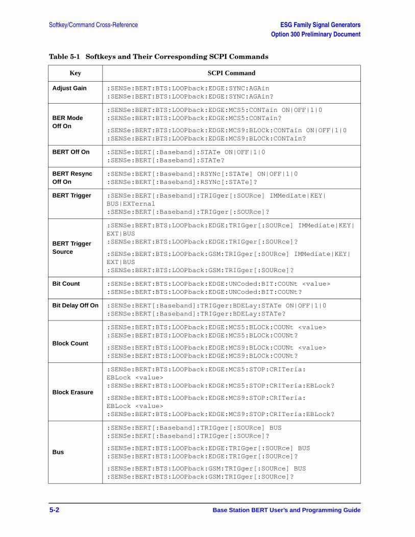
Softkey/Command Cross-Reference ESG Family Signal GeneratorsOption 300 Preliminary Document
5-2 Base Station BERT User’s and Programming Guide
Table 5-1 Softkeys and Their Corresponding SCPI Commands
Key SCPI Command
Adjust Gain :SENSe:BERT:BTS:LOOPback:EDGE:SYNC:AGAin :SENSe:BERT:BTS:LOOPback:EDGE:SYNC:AGAin?
BER Mode Off On
:SENSe:BERT:BTS:LOOPback:EDGE:MCS5:CONTain ON|OFF|1|0 :SENSe:BERT:BTS:LOOPback:EDGE:MCS5:CONTain?
:SENSe:BERT:BTS:LOOPback:EDGE:MCS9:BLOCk:CONTain ON|OFF|1|0 :SENSe:BERT:BTS:LOOPback:EDGE:MCS9:BLOCk:CONTain?
BERT Off On :SENSe:BERT[:Baseband]:STATe ON|OFF|1|0 :SENSe:BERT[:Baseband]:STATe?
BERT Resync Off On
:SENSe:BERT[:Baseband]:RSYNc[:STATe] ON|OFF|1|0:SENSe:BERT[:Baseband]:RSYNc[:STATe]?
BERT Trigger :SENSe:BERT[:Baseband]:TRIGger[:SOURce] IMMediate|KEY|BUS|EXTernal:SENSe:BERT[:Baseband]:TRIGger[:SOURce]?
BERT Trigger Source
:SENSe:BERT:BTS:LOOPback:EDGE:TRIGger[:SOURce] IMMediate|KEY|EXT|BUS:SENSe:BERT:BTS:LOOPback:EDGE:TRIGger[:SOURce]?
:SENSe:BERT:BTS:LOOPback:GSM:TRIGger[:SOURce] IMMediate|KEY|EXT|BUS:SENSe:BERT:BTS:LOOPback:GSM:TRIGger[:SOURce]?
Bit Count :SENSe:BERT:BTS:LOOPback:EDGE:UNCoded:BIT:COUNt <value> :SENSe:BERT:BTS:LOOPback:EDGE:UNCoded:BIT:COUNt?
Bit Delay Off On :SENSe:BERT[:Baseband]:TRIGger:BDELay:STATe ON|OFF|1|0:SENSe:BERT[:Baseband]:TRIGger:BDELay:STATe?
Block Count
:SENSe:BERT:BTS:LOOPback:EDGE:MCS5:BLOCk:COUNt <value> :SENSe:BERT:BTS:LOOPback:EDGE:MCS5:BLOCk:COUNt?
:SENSe:BERT:BTS:LOOPback:EDGE:MCS9:BLOCk:COUNt <value> :SENSe:BERT:BTS:LOOPback:EDGE:MCS9:BLOCk:COUNt?
Block Erasure
:SENSe:BERT:BTS:LOOPback:EDGE:MCS5:STOP:CRITeria:EBLock <value> :SENSe:BERT:BTS:LOOPback:EDGE:MCS5:STOP:CRITeria:EBLock?
:SENSe:BERT:BTS:LOOPback:EDGE:MCS9:STOP:CRITeria:EBLock <value> :SENSe:BERT:BTS:LOOPback:EDGE:MCS9:STOP:CRITeria:EBLock?
Bus
:SENSe:BERT[:Baseband]:TRIGger[:SOURce] BUS:SENSe:BERT[:Baseband]:TRIGger[:SOURce]?
:SENSe:BERT:BTS:LOOPback:EDGE:TRIGger[:SOURce] BUS:SENSe:BERT:BTS:LOOPback:EDGE:TRIGger[:SOURce]?
:SENSe:BERT:BTS:LOOPback:GSM:TRIGger[:SOURce] BUS:SENSe:BERT:BTS:LOOPback:GSM:TRIGger[:SOURce]?
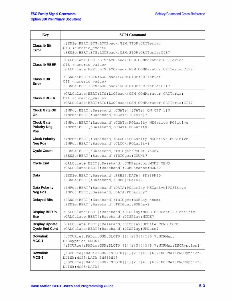
ESG Family Signal Generators Softkey/Command Cross-ReferenceOption 300 Preliminary Document
Base Station BERT User’s and Programming Guide 5-3
Class Ib Bit Error
:SENSe:BERT:BTS:LOOPback:GSM:STOP:CRITeria:CIB <numeric_event>:SENSe:BERT:BTS:LOOPback:GSM:STOP:CRITeria:CIB?
Class Ib RBER:CALCulate:BERT:BTS:LOOPback:GSM:COMParator:CRITeria:CIB <numeric_value>:CALCulate:BERT:BTS:LOOPback:GSM:COMParator:CRITeria:CIB?
Class II Bit Error
:SENSe:BERT:BTS:LOOPback:GSM:STOP:CRITeria:CII <numeric_value>:SENSe:BERT:BTS:LOOPback:GSM:STOP:CRITeria:CII?
Class II RBER:CALCulate:BERT:BTS:LOOPback:GSM:COMParator:CRITeria:CII <numeric_value>:CALCulate:BERT:BTS:LOOPback:GSM:COMParator:CRITeria:CII?
Clock Gate Off On
:INPut:BERT[:Baseband]:CGATe[:STATe] ON|OFF|1|0:INPut:BERT[:Baseband]:CGATe[:STATe]?
Clock Gate Polarity Neg Pos
:INPut:BERT[:Baseband]:CGATe:POLarity NEGative|POSitive:INPut:BERT[:Baseband]:CGATe:POLarity?
Clock Polarity Neg Pos
:INPut:BERT[:Baseband]:CLOCk:POLarity NEGative|POSitive :INPut:BERT[:Baseband]:CLOCk:POLarity?
Cycle Count :SENSe:BERT[:Baseband]:TRIGger:COUNt <num>:SENSe:BERT[:Baseband]:TRIGger:COUNt?
Cycle End :CALCulate:BERT[:Baseband]:COMParator:MODE CEND:CALCulate:BERT[:Baseband]:COMParator:MODE?
Data :SENSe:BERT[:Baseband]:PRBS[:DATA] PN9|PN15:SENSe:BERT[:Baseband]:PRBS[:DATA]?
Data Polarity Neg Pos
:INPut:BERT[:Baseband]:DATA:POLarity NEGative|POSitive:INPut:BERT[:Baseband]:DATA:POLarity?
Delayed Bits :SENSe:BERT[:Baseband]:TRIGger:BDELay <num>:SENSe:BERT[:Baseband]:TRIGger:BDELay?
Display BER % Exp
:CALCulate:BERT[:Baseband]:DISPlay:MODE PERCent|SCIentific :CALCulate:BERT[:Baseband]:DISPlay:MODE?
Display Update Cycle End Cont
:CALCulate:BERT[:Baseband]:DISPlay:UPDate CEND|CONT :CALCulate:BERT[:Baseband]:DISPlay:UPDate?
Downlink MCS-1
[:SOURce]:RADio:GSM:SLOT0|[1]|2|3|4|5|6|7:NORMal:ENCRyption DMCS1[:SOURce]:RADio:GSM:SLOT0|[1]|2|3|4|5|6|7:NORMal:ENCRyption?
Downlink MCS-5
[:SOURce]:RADio:EDGE:SLOT0|[1]|2|3|4|5|6|7:NORMal:ENCRyption:DLINk:MCS5:DATA PN9|PN15 [:SOURce]:RADio:EDGE:SLOT0|[1]|2|3|4|5|6|7:NORMal:ENCRyption:DLINk:MCS5:DATA?
Key SCPI Command
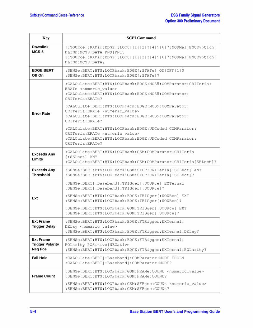
Softkey/Command Cross-Reference ESG Family Signal GeneratorsOption 300 Preliminary Document
5-4 Base Station BERT User’s and Programming Guide
Downlink MCS-5
[:SOURce]:RADio:EDGE:SLOT0|[1]|2|3|4|5|6|7:NORMal:ENCRyption:DLINk:MCS9:DATA PN9|PN15[:SOURce]:RADio:EDGE:SLOT0|[1]|2|3|4|5|6|7:NORMal:ENCRyption:DLINk:MCS9:DATA?
EDGE BERT Off On
:SENSe:BERT:BTS:LOOPback:EDGE[:STATe] ON|OFF|1|0:SENSe:BERT:BTS:LOOPback:EDGE[:STATe]?
Error Rate
:CALCulate:BERT:BTS:LOOPback:EDGE:MCS5:COMParator:CRITeria:ERATe <numeric_value>:CALCulate:BERT:BTS:LOOPback:EDGE:MCS5:COMParator:CRITeria:ERATe?
:CALCulate:BERT:BTS:LOOPback:EDGE:MCS9:COMParator:CRITeria:ERATe <numeric_value>:CALCulate:BERT:BTS:LOOPback:EDGE:MCS9:COMParator:CRITeria:ERATe?
:CALCulate:BERT:BTS:LOOPback:EDGE:UNCoded:COMParator:CRITeria:ERATe <numeric_value>:CALCulate:BERT:BTS:LOOPback:EDGE:UNCoded:COMParator:CRITeria:ERATe?
Exceeds Any Limits
:CALCulate:BERT:BTS:LOOPback:GSM:COMParator:CRITeria[:SELect] ANY:CALCulate:BERT:BTS:LOOPback:GSM:COMParator:CRITeria[SELect]?
Exceeds Any Threshold
:SENSe:BERT:BTS:LOOPback:GSM:STOP:CRITeria[:SELect] ANY:SENSe:BERT:BTS:LOOPback:GSM:STOP:CRITeria[:SELect]?
Ext
:SENSe:BERT[:Baseband]:TRIGger[:SOURce] EXTernal:SENSe:BERT[:Baseband]:TRIGger[:SOURce]?
:SENSe:BERT:BTS:LOOPback:EDGE:TRIGger[:SOURce] EXT:SENSe:BERT:BTS:LOOPback:EDGE:TRIGger[:SOURce]?
:SENSe:BERT:BTS:LOOPback:GSM:TRIGger[:SOURce] EXT:SENSe:BERT:BTS:LOOPback:GSM:TRIGger[:SOURce]?
Ext Frame Trigger Delay
:SENSe:BERT:BTS:LOOPback:EDGE:FTRigger:EXTernal:DELay <numaric_value>:SENSe:BERT:BTS:LOOPback:EDGE:FTRigger:EXTernal:DELay?
Ext Frame Trigger Polarity Neg Pos
:SENSe:BERT:BTS:LOOPback:EDGE:FTRigger:EXTernal:POLarity POSitive|NEGative:SENSe:BERT:BTS:LOOPback:EDGE:FTRigger:EXTernal:POLarity?
Fail Hold :CALCulate:BERT[:Baseband]:COMParator:MODE FHOLd :CALCulate:BERT[:Baseband]:COMParator:MODE?
Frame Count:SENSe:BERT:BTS:LOOPback:GSM:FRAMe:COUNt <numeric_value>:SENSe:BERT:BTS:LOOPback:GSM:FRAMe:COUNt?
:SENSe:BERT:BTS:LOOPback:GSM:SFRame:COUNt <numeric_value>:SENSe:BERT:BTS:LOOPback:GSM:SFRame:COUNt?
Key SCPI Command
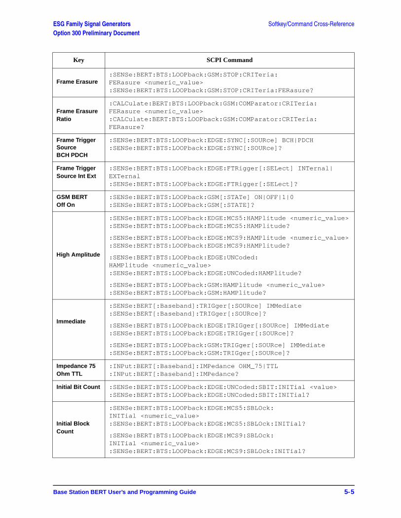
ESG Family Signal Generators Softkey/Command Cross-ReferenceOption 300 Preliminary Document
Base Station BERT User’s and Programming Guide 5-5
Frame Erasure:SENSe:BERT:BTS:LOOPback:GSM:STOP:CRITeria:FERasure <numeric_value>:SENSe:BERT:BTS:LOOPback:GSM:STOP:CRITeria:FERasure?
Frame Erasure Ratio
:CALCulate:BERT:BTS:LOOPback:GSM:COMParator:CRITeria:FERasure <numeric_value>:CALCulate:BERT:BTS:LOOPback:GSM:COMParator:CRITeria:FERasure?
Frame Trigger SourceBCH PDCH
:SENSe:BERT:BTS:LOOPback:EDGE:SYNC[:SOURce] BCH|PDCH :SENSe:BERT:BTS:LOOPback:EDGE:SYNC[:SOURce]?
Frame Trigger Source Int Ext
:SENSe:BERT:BTS:LOOPback:EDGE:FTRigger[:SELect] INTernal|EXTernal :SENSe:BERT:BTS:LOOPback:EDGE:FTRigger[:SELect]?
GSM BERT Off On
:SENSe:BERT:BTS:LOOPback:GSM[:STATe] ON|OFF|1|0:SENSe:BERT:BTS:LOOPback:GSM[:STATE]?
High Amplitude
:SENSe:BERT:BTS:LOOPback:EDGE:MCS5:HAMPlitude <numeric_value>:SENSe:BERT:BTS:LOOPback:EDGE:MCS5:HAMPlitude?
:SENSe:BERT:BTS:LOOPback:EDGE:MCS9:HAMPlitude <numeric_value>:SENSe:BERT:BTS:LOOPback:EDGE:MCS9:HAMPlitude?
:SENSe:BERT:BTS:LOOPback:EDGE:UNCoded:HAMPlitude <numeric_value>:SENSe:BERT:BTS:LOOPback:EDGE:UNCoded:HAMPlitude?
:SENSe:BERT:BTS:LOOPback:GSM:HAMPlitude <numeric_value> :SENSe:BERT:BTS:LOOPback:GSM:HAMPlitude?
Immediate
:SENSe:BERT[:Baseband]:TRIGger[:SOURce] IMMediate:SENSe:BERT[:Baseband]:TRIGger[:SOURce]?
:SENSe:BERT:BTS:LOOPback:EDGE:TRIGger[:SOURce] IMMediate:SENSe:BERT:BTS:LOOPback:EDGE:TRIGger[:SOURce]?
:SENSe:BERT:BTS:LOOPback:GSM:TRIGger[:SOURce] IMMediate:SENSe:BERT:BTS:LOOPback:GSM:TRIGger[:SOURce]?
Impedance 75 Ohm TTL
:INPut:BERT[:Baseband]:IMPedance OHM_75|TTL:INPut:BERT[:Baseband]:IMPedance?
Initial Bit Count :SENSe:BERT:BTS:LOOPback:EDGE:UNCoded:SBIT:INITial <value> :SENSe:BERT:BTS:LOOPback:EDGE:UNCoded:SBIT:INITial?
Initial Block Count
:SENSe:BERT:BTS:LOOPback:EDGE:MCS5:SBLOck:INITial <numeric_value>:SENSe:BERT:BTS:LOOPback:EDGE:MCS5:SBLOck:INITial?
:SENSe:BERT:BTS:LOOPback:EDGE:MCS9:SBLOck:INITial <numeric_value>:SENSe:BERT:BTS:LOOPback:EDGE:MCS9:SBLOck:INITial?
Key SCPI Command
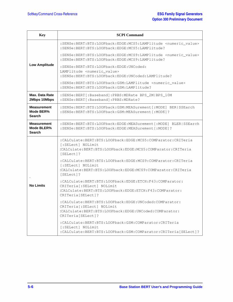
Softkey/Command Cross-Reference ESG Family Signal GeneratorsOption 300 Preliminary Document
5-6 Base Station BERT User’s and Programming Guide
Low Amplitude
:SENSe:BERT:BTS:LOOPback:EDGE:MCS5:LAMPlitude <numeric_value>:SENSe:BERT:BTS:LOOPback:EDGE:MCS5:LAMPlitude?
:SENSe:BERT:BTS:LOOPback:EDGE:MCS9:LAMPlitude <numeric_value>:SENSe:BERT:BTS:LOOPback:EDGE:MCS9:LAMPlitude?
:SENSe:BERT:BTS:LOOPback:EDGE:UNCoded:LAMPlitude <numeric_value>:SENSe:BERT:BTS:LOOPback:EDGE:UNCoded:LAMPlitude?
:SENSe:BERT:BTS:LOOPback:GSM:LAMPlitude <numeric_value> :SENSe:BERT:BTS:LOOPback:GSM:LAMPlitude?
Max. Data Rate 2Mbps 10Mbps
:SENSe:BERT[:Baseband]:PRBS:MDRate BPS_2M|BPS_10M:SENSe:BERT[:Baseband]:PRBS:MDRate?
Measurement Mode BER% Search
:SENSe:BERT:BTS:LOOPback:GSM:MEASurement[:MODE] BER|SSEarch:SENSe:BERT:BTS:LOOPback:GSM:MEASurement[:MODE]?
Measurement Mode BLER% Search
:SENSe:BERT:BTS:LOOPback:EDGE:MEASurement[:MODE] BLER|SSEarch:SENSe:BERT:BTS:LOOPback:EDGE:MEASurement[:MODE]?
.
No Limits
:CALCulate:BERT:BTS:LOOPback:EDGE:MCS5:COMParator:CRITeria[:SELect] NOLimit:CALCulate:BERT:BTS:LOOPback:EDGE:MCS5:COMParator:CRITeria[SELect]?
:CALCulate:BERT:BTS:LOOPback:EDGE:MCS9:COMParator:CRITeria[:SELect] NOLimit:CALCulate:BERT:BTS:LOOPback:EDGE:MCS9:COMParator:CRITeria[SELect]?
:CALCulate:BERT:BTS:LOOPback:EDGE:ETCH:F43:COMParator:CRITeria[:SELect] NOLimit:CALCulate:BERT:BTS:LOOPback:EDGE:ETCH:F43:COMParator:CRITeria[SELect]?
:CALCulate:BERT:BTS:LOOPback:EDGE:UNCoded:COMParator:CRITeria[:SELect] NOLimit:CALCulate:BERT:BTS:LOOPback:EDGE:UNCoded:COMParator:CRITeria[SELect]?
:CALCulate:BERT:BTS:LOOPback:GSM:COMParator:CRITeria[:SELect] NOLimit:CALCulate:BERT:BTS:LOOPback:GSM:COMParator:CRITeria[SELect]?
Key SCPI Command
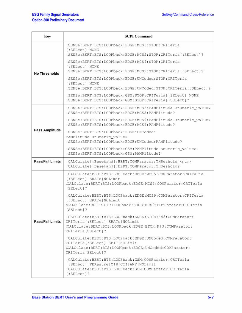
ESG Family Signal Generators Softkey/Command Cross-ReferenceOption 300 Preliminary Document
Base Station BERT User’s and Programming Guide 5-7
No Thresholds
:SENSe:BERT:BTS:LOOPback:EDGE:MCS5:STOP:CRITeria[:SELect] NONE :SENSe:BERT:BTS:LOOPback:EDGE:MCS5:STOP:CRITeria[:SELect]?
:SENSe:BERT:BTS:LOOPback:EDGE:MCS9:STOP:CRITeria[:SELect] NONE :SENSe:BERT:BTS:LOOPback:EDGE:MCS9:STOP:CRITeria[:SELect]?
:SENSe:BERT:BTS:LOOPback:EDGE:UNCoded:STOP:CRITeria[:SELect] NONE :SENSe:BERT:BTS:LOOPback:EDGE:UNCoded:STOP:CRITeria[:SELect]?
:SENSe:BERT:BTS:LOOPback:GSM:STOP:CRITeria[:SELect] NONE:SENSe:BERT:BTS:LOOPback:GSM:STOP:CRITeria[:SELect]?
Pass Amplitude
:SENSe:BERT:BTS:LOOPback:EDGE:MCS5:PAMPlitude <numeric_value>:SENSe:BERT:BTS:LOOPback:EDGE:MCS5:PAMPlitude?
:SENSe:BERT:BTS:LOOPback:EDGE:MCS9:PAMPlitude <numeric_value>:SENSe:BERT:BTS:LOOPback:EDGE:MCS9:PAMPlitude?
:SENSe:BERT:BTS:LOOPback:EDGE:UNCoded:PAMPlitude <numeric_value>:SENSe:BERT:BTS:LOOPback:EDGE:UNCoded:PAMPlitude?
:SENSe:BERT:BTS:LOOPback:GSM:PAMPlitude <numeric_value> :SENSe:BERT:BTS:LOOPback:GSM:PAMPlitude?
Pass/Fail Limits :CALCulate[:Baseband]:BERT:COMParator:THReshold <num>:CALCulate[:Baseband]:BERT:COMParator:THReshold?
Pass/Fail Limits
:CALCulate:BERT:BTS:LOOPback:EDGE:MCS5:COMParator:CRITeria[:SELect] ERATe|NOLimit:CALCulate:BERT:BTS:LOOPback:EDGE:MCS5:COMParator:CRITeria[SELect]?
:CALCulate:BERT:BTS:LOOPback:EDGE:MCS9:COMParator:CRITeria[:SELect] ERATe|NOLimit:CALCulate:BERT:BTS:LOOPback:EDGE:MCS9:COMParator:CRITeria[SELect]?
:CALCulate:BERT:BTS:LOOPback:EDGE:ETCH:F43:COMParator:CRITeria[:SELect] ERATe|NOLimit:CALCulate:BERT:BTS:LOOPback:EDGE:ETCH:F43:COMParator:CRITeria[SELect]?
:CALCulate:BERT:BTS:LOOPback:EDGE:UNCoded:COMParator:CRITeria[:SELect] EBIT|NOLimit:CALCulate:BERT:BTS:LOOPback:EDGE:UNCoded:COMParator:CRITeria[SELect]?
:CALCulate:BERT:BTS:LOOPback:GSM:COMParator:CRITeria[:SELect] FERasure|CIB|CII|ANY|NOLimit:CALCulate:BERT:BTS:LOOPback:GSM:COMParator:CRITeria[:SELect]?
Key SCPI Command
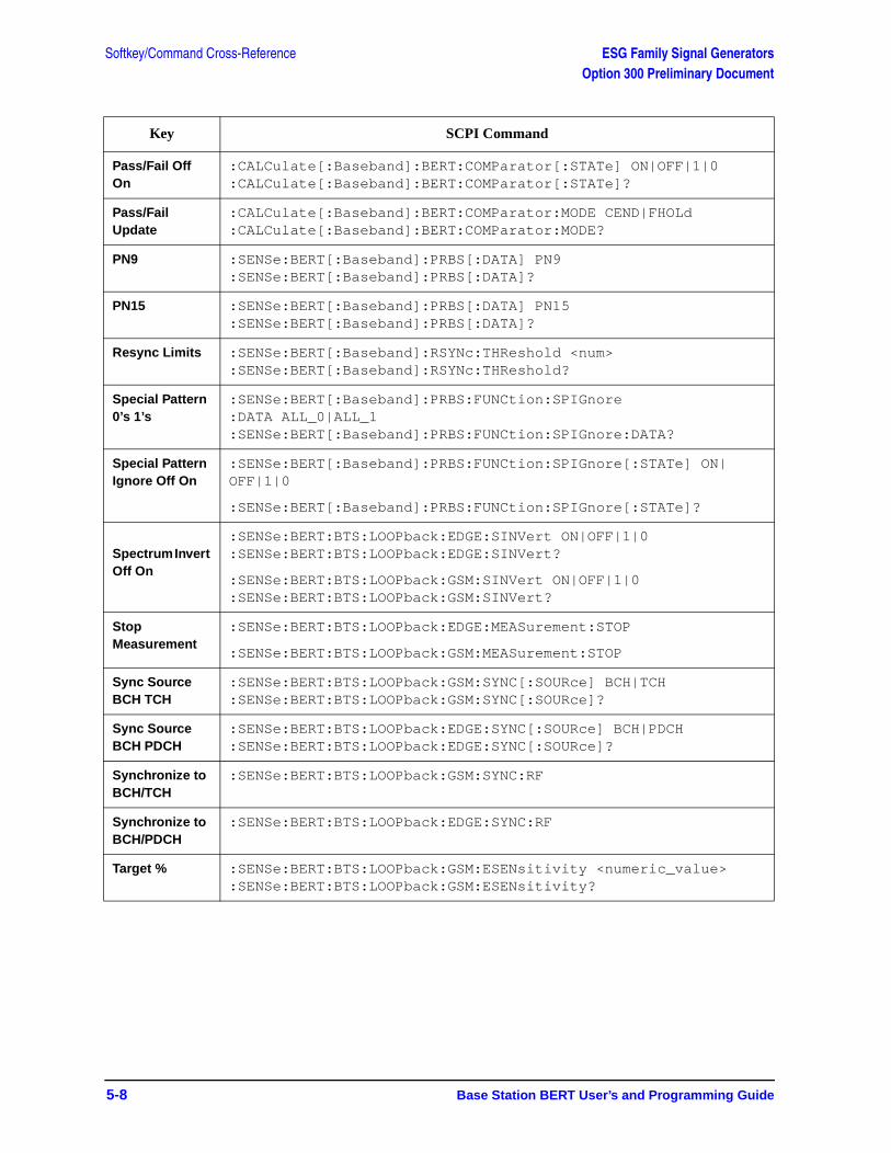
Softkey/Command Cross-Reference ESG Family Signal GeneratorsOption 300 Preliminary Document
5-8 Base Station BERT User’s and Programming Guide
Pass/Fail Off On
:CALCulate[:Baseband]:BERT:COMParator[:STATe] ON|OFF|1|0:CALCulate[:Baseband]:BERT:COMParator[:STATe]?
Pass/Fail Update
:CALCulate[:Baseband]:BERT:COMParator:MODE CEND|FHOLd :CALCulate[:Baseband]:BERT:COMParator:MODE?
PN9 :SENSe:BERT[:Baseband]:PRBS[:DATA] PN9:SENSe:BERT[:Baseband]:PRBS[:DATA]?
PN15 :SENSe:BERT[:Baseband]:PRBS[:DATA] PN15:SENSe:BERT[:Baseband]:PRBS[:DATA]?
Resync Limits :SENSe:BERT[:Baseband]:RSYNc:THReshold <num> :SENSe:BERT[:Baseband]:RSYNc:THReshold?
Special Pattern 0’s 1’s
:SENSe:BERT[:Baseband]:PRBS:FUNCtion:SPIGnore:DATA ALL_0|ALL_1:SENSe:BERT[:Baseband]:PRBS:FUNCtion:SPIGnore:DATA?
Special Pattern Ignore Off On
:SENSe:BERT[:Baseband]:PRBS:FUNCtion:SPIGnore[:STATe] ON|OFF|1|0
:SENSe:BERT[:Baseband]:PRBS:FUNCtion:SPIGnore[:STATe]?
Spectrum Invert Off On
:SENSe:BERT:BTS:LOOPback:EDGE:SINVert ON|OFF|1|0:SENSe:BERT:BTS:LOOPback:EDGE:SINVert?
:SENSe:BERT:BTS:LOOPback:GSM:SINVert ON|OFF|1|0:SENSe:BERT:BTS:LOOPback:GSM:SINVert?
Stop Measurement
:SENSe:BERT:BTS:LOOPback:EDGE:MEASurement:STOP
:SENSe:BERT:BTS:LOOPback:GSM:MEASurement:STOP
Sync Source BCH TCH
:SENSe:BERT:BTS:LOOPback:GSM:SYNC[:SOURce] BCH|TCH:SENSe:BERT:BTS:LOOPback:GSM:SYNC[:SOURce]?
Sync Source BCH PDCH
:SENSe:BERT:BTS:LOOPback:EDGE:SYNC[:SOURce] BCH|PDCH :SENSe:BERT:BTS:LOOPback:EDGE:SYNC[:SOURce]?
Synchronize to BCH/TCH
:SENSe:BERT:BTS:LOOPback:GSM:SYNC:RF
Synchronize to BCH/PDCH
:SENSe:BERT:BTS:LOOPback:EDGE:SYNC:RF
Target % :SENSe:BERT:BTS:LOOPback:GSM:ESENsitivity <numeric_value>:SENSe:BERT:BTS:LOOPback:GSM:ESENsitivity?
Key SCPI Command
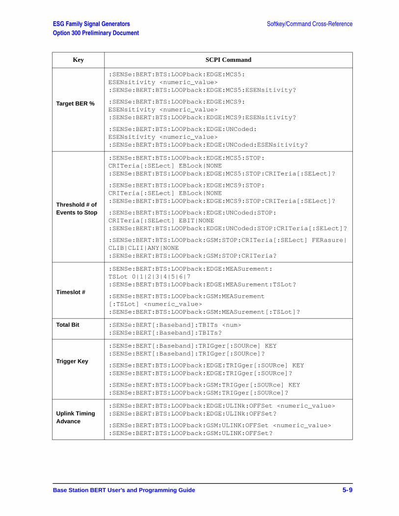
ESG Family Signal Generators Softkey/Command Cross-ReferenceOption 300 Preliminary Document
Base Station BERT User’s and Programming Guide 5-9
Target BER %
:SENSe:BERT:BTS:LOOPback:EDGE:MCS5:ESENsitivity <numeric_value>:SENSe:BERT:BTS:LOOPback:EDGE:MCS5:ESENsitivity?
:SENSe:BERT:BTS:LOOPback:EDGE:MCS9:ESENsitivity <numeric_value>:SENSe:BERT:BTS:LOOPback:EDGE:MCS9:ESENsitivity?
:SENSe:BERT:BTS:LOOPback:EDGE:UNCoded:ESENsitivity <numeric_value>:SENSe:BERT:BTS:LOOPback:EDGE:UNCoded:ESENsitivity?
Threshold # of Events to Stop
:SENSe:BERT:BTS:LOOPback:EDGE:MCS5:STOP:CRITeria[:SELect] EBLock|NONE :SENSe:BERT:BTS:LOOPback:EDGE:MCS5:STOP:CRITeria[:SELect]?
:SENSe:BERT:BTS:LOOPback:EDGE:MCS9:STOP:CRITeria[:SELect] EBLock|NONE :SENSe:BERT:BTS:LOOPback:EDGE:MCS9:STOP:CRITeria[:SELect]?
:SENSe:BERT:BTS:LOOPback:EDGE:UNCoded:STOP:CRITeria[:SELect] EBIT|NONE :SENSe:BERT:BTS:LOOPback:EDGE:UNCoded:STOP:CRITeria[:SELect]?
:SENSe:BERT:BTS:LOOPback:GSM:STOP:CRITeria[:SELect] FERasure|CLIB|CLII|ANY|NONE:SENSe:BERT:BTS:LOOPback:GSM:STOP:CRITeria?
Timeslot #
:SENSe:BERT:BTS:LOOPback:EDGE:MEASurement:TSLot 0|1|2|3|4|5|6|7:SENSe:BERT:BTS:LOOPback:EDGE:MEASurement:TSLot?
:SENSe:BERT:BTS:LOOPback:GSM:MEASurement[:TSLot] <numeric_value>:SENSe:BERT:BTS:LOOPback:GSM:MEASurement[:TSLot]?
Total Bit :SENSe:BERT[:Baseband]:TBITs <num>:SENSe:BERT[:Baseband]:TBITs?
Trigger Key
:SENSe:BERT[:Baseband]:TRIGger[:SOURce] KEY:SENSe:BERT[:Baseband]:TRIGger[:SOURce]?
:SENSe:BERT:BTS:LOOPback:EDGE:TRIGger[:SOURce] KEY:SENSe:BERT:BTS:LOOPback:EDGE:TRIGger[:SOURce]?
:SENSe:BERT:BTS:LOOPback:GSM:TRIGger[:SOURce] KEY:SENSe:BERT:BTS:LOOPback:GSM:TRIGger[:SOURce]?
Uplink Timing Advance
:SENSe:BERT:BTS:LOOPback:EDGE:ULINk:OFFSet <numeric_value>:SENSe:BERT:BTS:LOOPback:EDGE:ULINk:OFFSet?
:SENSe:BERT:BTS:LOOPback:GSM:ULINK:OFFSet <numeric_value>:SENSe:BERT:BTS:LOOPback:GSM:ULINK:OFFSet?
Key SCPI Command
Softkey/Command Cross-Reference ESG Family Signal GeneratorsOption 300 Preliminary Document
5-10 Base Station BERT User’s and Programming Guide
Base Station BERT User’s and Programming Guide 6-1
ESG Family Signal GeneratorsOption 300 Preliminary Document
6 Theory of Operation
Look in this chapter for in-depth explanations of loopback base station receiver test functionality.
Theory of Operation ESG Family Signal GeneratorsSynchronization Option 300 Preliminary Document
6-2 Base Station BERT User’s and Programming Guide
SynchronizationSynchronizing the test equipment to the base transceiver station (BTS) is a prerequisite to the BTS looping back the selected traffic channel (TCH). This can be achieved in two ways: BCH Sync or TCH Sync.
BCH Sync The BTS is set to transmit to the test equipment a BCH on timeslot 0 of a selected absolute radio frequency channel number (ARFCN). The test equipment uses the BCH signal to determine its required TCH transmit timing.
On completion, the BTS may be switched into loopback mode on any selected ARFCN and timeslot number.
TCH Sync This is a very quick mode of synchronization, but take care initially to set the receiver to the correct timeslot number being transmitted by the BTS.
In this mode the base station must transmit a signal on the selected timeslot prior to data being looped back. In some base stations this will happen as soon as a timeslot is set to loopback, regardless of whether the signal to the BTS has the correct timing. In other base stations, the BTS may need to be set to transmit a signal in the selected timeslot prior to achieving synchronization.
The test equipment can lock to this signal if it contains the correct midamble. Once synchronized, the test equipment uses this information to determine the required TCH transmit timing. If the BTS is set accordingly, any timeslot can be transmitted with the correct timing to enable it to be looped back by the BTS to the receiver (VSA/ESG).
NOTE The TCH sync mode relies on the user to set the correct timeslot number into both ESG transmitter and receiver during synchronization. Thereafter, the ESG can correctly test any timeslot since its relative timing is defined.
NOTE This capability can be used to speed up test of consecutive timeslots in manufacture. TCH sync mode can be used to test all timeslots consecutively without changing a single setting on the ESG/VSA. All that is required is to consecutively loopback each timeslot using the BTS MMI and resynchronize and trigger the ESG.
PN synchronization is also a prerequisite to BER measurements. This is automatic but is dependent on prior BCH or TCH synchronization.
The pattern to be recognized (PN9 or PN15) is determined by the corresponding transmit timeslot pattern selection.
ESG Family Signal Generators Theory of OperationOption 300 Preliminary Document Erased Frame Detection
Base Station BERT User’s and Programming Guide 6-3
Erased Frame DetectionWhen an incorrect CRC in an uplink speech frame is detected by a BTS conforming to the GSM standards, the BTS substitutes an all-zero speech frame.
In the loopback mode, the BTS transmitter then recodes this substituted zero speech frame before transmission back to the test equipment receiver (VSA/ESG).
The ESG receiver detects any coded all-zeros speech frames in the returned downlink signal and increments the (erased) frame event count.
Theory of Operation ESG Family Signal GeneratorsDownlink Errors Option 300 Preliminary Document
6-4 Base Station BERT User’s and Programming Guide
Downlink ErrorsThe loopback method of measuring BTS receiver BER quality requires a high quality downlink return path which introduces no errors.
To cater for the situation where the downlink path is faulty, the VSA/ESG provides a measure of downlink quality based on TCH payload errors detected by convolutional decoding of the return path. This records errors introduced into the TCH between the downlink coding (BTS transmitter) and decoding (VSA/ESG) processes and should normally be zero. For any payload errors detected during a measurement, the measurement is extended by a speech frame for every downlink error detected.
If a downlink problem results in errors introduced into the downlink midamble, the measurement aborts, providing further security against downlink problems.
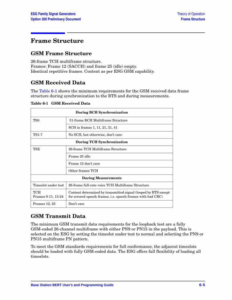
ESG Family Signal Generators Theory of OperationOption 300 Preliminary Document Frame Structure
Base Station BERT User’s and Programming Guide 6-5
Frame Structure
GSM Frame Structure26-frame TCH multiframe structure. Frames: Frame 12 (SACCH) and frame 25 (idle) empty.Identical repetitive frames. Content as per ESG GSM capability.
GSM Received DataThe Table 6-1 shows the minimum requirements for the GSM received data frame structure during synchronization to the BTS and during measurements.
Table 6-1 GSM Received Data
GSM Transmit DataThe minimum GSM transmit data requirements for the loopback test are a fully GSM-coded 26-channel multiframe with either PN9 or PN15 in the payload. This is selected on the ESG by setting the timeslot under test to normal and selecting the PN9 or PN15 multiframe PN pattern.
To meet the GSM standards requirements for full conformance, the adjacent timeslots should be loaded with fully GSM-coded data. The ESG offers full flexibility of loading all timeslots.
During BCH Synchronization
TS0 51-frame BCH Multiframe Structure
SCH in frames 1, 11, 21, 31, 41
TS1-7 No SCH, but otherwise, don’t care
During TCH Synchronization
TSX 26-frame TCH Multiframe Structure
Frame 25 idle
Frame 12 don’t care
Other frames TCH
During Measurements
Timeslot under test 26-frame full-rate voice TCH Multiframe Structure
TCHFrames 0-11, 13-24
Content determined by transmitted signal (looped by BTS except for errored speech frames, i.e. speech frames with bad CRC)
Frames 12, 25 Don’t care
Theory of Operation ESG Family Signal GeneratorsFrame Structure Option 300 Preliminary Document
6-6 Base Station BERT User’s and Programming Guide
Edge Frame Structure 52-frame PDCH multiframe structure.
Frames: 12 blocks of 4 frames, 2 idle frames, and 2 frames used for the PTCCH.

Index
Index I-1
AAdjust Gain softkey, 3-3amplitude sensitivity search, 2-11Arm Sensitivity Search softkey, 3-3
BBCH synchronization, 2-7BER connectors
BER CLK IN, 3-38BER DATA IN, 3-38BER ERR OUT, 3-39BER GATE IN, 3-38BER MEAS END, 3-38BER NO DATA, 3-39BER SYNC LOSS, 3-39BER TEST OUT, 3-39
BER% Mode Off On softkey, 3-4BER% Uncoded Configure softkey, 3-3BERT softkey, 3-4BERT softkeys
Baseband BERT, 3-3BERT Off On, 3-4BERT Resync Off On, 3-4BERT Trigger, 3-4Trigger Source, 3-5
BERT Trigger SourceSCPI command, 5-2
Bit CountSCPI command, 4-7
Bit Count softkey, 3-5Bit Delay Off On softkey, 3-5BLER% Configure softkey, 3-6BLER% MCS5 Configure softkey, 3-5BLER% MCS9 Configure softkey, 3-6Block Count softkey, 3-6Block Erasure softkey, 3-6BTS BERT EDGE Loopback softkey, 3-7BTS BERT GSM Loopback softkey, 3-7Bus
SCPI command, 5-2Bus softkey, 3-7
CChannel Band softkey, 3-7Channel Number softkey, 3-8Class Ib Bit Error
SCPI command, 5-3
Class Ib Bit Error softkey, 3-8Class Ib RBER
SCPI command, 5-3Class Ib RBER softkey, 3-8Class II Bit Error
SCPI command, 5-3Class II Bit Error softkey, 3-9Class II RBER
SCPI command, 5-3Class II RBER softkey, 3-9Clock Gate Off On softkey, 3-9Clock Gate Polarity Neg Pos softkey, 3-9Clock Polarity Neg Pos softkey, 3-10Configure BER% softkey, 3-10Configure BERT softkey, 3-10Configure Measurement softkey, 3-10Configure Sensitivity Search softkey, 3-10Configure Triggers softkey, 3-11connecting the test equipment, 2-3connectors
BER CLK IN, 3-38BER DATA IN, 3-38BER ERR OUT, 3-39BER GATE IN, 3-38BER MEAS END, 3-38BER NO DATA, 3-39BER SYNC LOSS, 3-39BER TEST OUT, 3-39
Cycle Count softkey, 3-11Cycle End softkey, 3-11
DData Polarity Neg Pos softkey, 3-12Data softkey, 3-11Delayed Bits softkey, 3-12display annotation, 3-35Display BER % Exp softkey, 3-12Display Update Cycle End Cont softkey, 3-12downlink errors, 6-4Downlink MCS-1 softkey, 3-13Downlink MCS-5, 3-13, 3-33Downlink MCS-5 softkey, 3-13Downlink MCS-9 softkey, 3-13
EEDGE BERT Off On softkey, 3-13EDGE frame structure, 6-6
I-2 Index
Index
equipment setup, 2-3erased frame detection, 6-3Error Count softkey, 3-14Error Rate softkey, 3-14ESG
configuring GSM mode, 2-4ESG-D series required options, 2-2E-TCH/F43.2 softkey, 3-14Exceeds Any Limits
SCPI command, 5-4Exceeds Any Limits softkey, 3-14Exceeds Any Threshold
SCPI command, 5-4Exceeds Any Threshold softkey, 3-15Ext
SCPI command, 5-4Ext Frame Trigger Delay softkey, 3-15Ext Frame Trigger Polarity Neg Pos softkey, 3-15Ext softkey, 3-15external frame trigger, 2-13
adjusting delay, 2-14measuring delay, 2-13
FFail Hold softkey, 3-15Frame Count
SCPI command, 5-4Frame Count softkey, 3-16Frame Erasure Ratio
SCPI command, 5-5Frame Erasure Ratio softkey, 3-17Frame Erasure softkey, 3-16Frame Repeat Single Cont softkey, 3-17frame structure, 6-5Frame Trigger Source BCH PDCH softkey, 3-18Frame Trigger Source Int Ext softkey, 3-18Freq Channel softkeys
GSM 850 Base, 3-20Freq Channels Off On softkey, 3-19Freq Channels softkey, 3-19Freq Channels softkeys
GSM 450/850 Base, 3-19, 3-20GSM 450/850 Mobile, 3-19, 3-20GSM 480 Mobile, 3-20GSM 850 Mobile, 3-21
GGSM BERT Off On
SCPI command, 5-5
GSM BERT Off On softkey, 3-21GSM frame structure, 6-5GSM mode
configuring the ESG, 2-4configuring the VSA, 2-3
GSM/EDGE base station test softkeys, 3-2
HHigh Amplitude
SCPI command, 5-5High Amplitude softkey, 3-21
IImmediate
SCPI command, 5-5Immediate softkey, 3-22Impedance 75 Ohm TTL softkey, 3-22Initial Bit Count softkey, 3-22Initial Block Count softkey, 3-22
Lloopback BER
measuring, 2-9Low Amplitude
SCPI command, 5-6Low Amplitude softkey, 3-23
MMax. Data Rate 2Mbps 10Mbps softkey, 3-23Measurement Mode BER% Search
SCPI command, 5-6Measurement Mode BER% Search softkey, 3-23measuring RF loopback BER, 2-2Mode hardkey, 3-2Multiframe Channel softkey, 3-24
NNo Limits
SCPI command, 5-6No Limits softkey, 3-24No Thresholds
SCPI command, 5-7No Thresholds softkey, 3-24
OOption 300 overview, 1-2overview, 1-2
Index
Index I-3
PPass Amplitude
SCPI command, 5-7Pass Amplitude softkey, 3-25, 3-26Pass/Fail Limits
SCPI command, 5-7Pass/Fail Limits softkey, 3-26Pass/Fail Off On softkey, 3-26Pass/Fail Update softkey, 3-27PN15 softkey, 3-25PN9 softkey, 3-25product overview, 1-2programming commands, 4-1
Rrear panel overview, 3-38remote commands, 4-1required equipment, 2-2Restore EDGE Factory Default softkey, 3-27Restore GSM Factory Default softkey, 3-27Resync Limits softkey, 3-27RF loopback BER measurement, 2-2
SSCPI commands, 4-1
BER clock gate polarity, 4-2BER clock gate state, 4-2BER clock polarity, 4-2BER cycle count, 4-2BER data pattern, 4-3BER data polarity, 4-3BER display mode, 4-3BER display update mode, 4-3BER input impedance, 4-3BER maximum data rate, 4-4BER measurement result query, 4-4BER pass/fail judgement mode, 4-5BER pass/fail limits, 4-5BER pass/fail state, 4-5BER resync limits, 4-5BER resynchronization state, 4-6BER special pattern ignore data, 4-6BER special pattern ignore state, 4-6BER total bits, 4-6BER trigger
bit delay state, 4-7BER trigger bit delay, 4-6BER trigger source, 4-7BERT State, 4-7
SCPI commands (Continued)BERT trigger source selection, 4-7bit count, 4-8BLER measurement, 4-8, 4-9block count, 4-9class Ib bits, 4-9class II bits, 4-9data, 4-9external frame trigger delay, 4-12external frame trigger polarity, 4-12frame count DER %, 4-12frame synchronization source, 4-12frame trigger source, 4-12loopback operating state, 4-13measurement mode switching, 4-14measurement sensitivity, 4-14measurement stopping, 4-15pass/fail limit
class Ib RBER, 4-16class II RBER, 4-16frame erasure ratio, 4-16selection, 4-17
sensitivity searchbit count, 4-18frame count, 4-18high amplitude, 4-20initial bit count, 4-18initial block count, 4-19initial frame count, 4-19low amplitude, 4-20pass amplitude, 4-21target error level, 4-19
spectrum invert, 4-21, 4-22stop measurement threshold criteria
class Ib, 4-25class II, 4-25frame erasure, 4-25number of events, 4-25
sync signal adjustment, 4-27sync source, 4-27synchronizing, 4-27timeslot selection, 4-28uplink timing advance, 4-29
Search DL MCS5 Configure softkey, 3-28Search DL MCS9 Configure softkey, 3-28Search Uncoded Configure softkey, 3-28Sensitivity Search Configure softkey, 3-28setup, equipment required, 2-2softkey descriptions, 3-1softkeys
Adjust Gain, 3-3Arm Sensitivity Search, 3-3Baseband BERT, 3-3
I-4 Index
Index
softkeys (Continued)BER% Mode Off On, 3-4BER% Uncoded Configure, 3-3BERT, 3-4BERT Off On, 3-4BERT Resync Off On, 3-4BERT Trigger, 3-4BERT Trigger Source, 3-5Bit Count, 3-5Bit Delay Off On, 3-5BLER% Configure, 3-6BLER% MCS5 Configure, 3-5BLER% MCS9 Configure, 3-6Block Count, 3-6Block Erasure, 3-6BTS BERT EDGE Loopback, 3-7BTS BERT GSM Loopback, 3-7Bus, 3-7Channel Band, 3-7Channel Number, 3-8Class ib Bit Error, 3-8Class ib RBER, 3-8Class II Bit Error, 3-9Class II RBER, 3-9Clock Gate Off On, 3-9Clock Gate Polarity Neg Pos, 3-9Clock Polarity Neg Pos, 3-10Configure BER%, 3-10Configure BERT, 3-10Configure Measurement, 3-10Configure Sensitivity Search, 3-10Configure Triggers, 3-11Cycle Count, 3-11Cycle End, 3-11Data, 3-11Data Polarity Neg Pos, 3-12Delayed Bits, 3-12Display BER% Exp, 3-12Display Update Cycle End Cont, 3-12Downlink MCS-1, 3-13Downlink MCS-5, 3-13Downlink MCS-9, 3-13EDGE BERT Off On, 3-13Error Count, 3-14Error Rate, 3-14E-TCH/F43.2, 3-14Exceeds Any Limits, 3-14Exceeds Any Threshold, 3-15Ext, 3-15Ext Frame Trigger Delay, 3-15Ext Frame Trigger Polarity Neg Pos, 3-15Fail Hold, 3-15
softkeys (Continued)Frame Count, 3-16Frame Erasure, 3-16Frame Erasure Ratio, 3-17Frame Repeat Single Cont, 3-17Frame Trigger Source BCH PDCH, 3-18Frame Trigger Source Int Ext, 3-18Freq Channels, 3-19Freq Channels Off On, 3-19GSM 450 Base, 3-19GSM 450 Mobile, 3-19GSM 450/850 Base, 3-20GSM 450/850 Mobile, 3-20GSM 480 Mobile, 3-20GSM 850 Base, 3-20GSM 850 Mobile, 3-21GSM BERT Off On, 3-21High Amplitude, 3-21Immediate, 3-22Impedance 75 Ohm TTL, 3-22Initial Bit Count, 3-22Initial Block Count, 3-22Low Amplitude, 3-23Max. Data Rate 2Mbps 10Mbps, 3-23Measurement Mode BER% Search, 3-23Measurement Mode BLER% Search, 3-23Multiframe Channel, 3-24No Limits, 3-24No Thresholds, 3-24Pass Amplitude, 3-25, 3-26Pass/Fail Limits, 3-26Pass/Fail Off On, 3-26Pass/Fail Update, 3-27PN15, 3-25PN9, 3-25Restore EDGE Factory Default, 3-27Restore GSM Factory Default, 3-27Resync Limits, 3-27Search DL MCS5 Configure, 3-28Search DL MCS9 Configure, 3-28Search Uncoded Configure, 3-28Sensitivity Search Configure, 3-28Special Pattern Ignore Off On, 3-29Special Pattern O’s 1’s, 3-28Spectrum Invert Off On, 3-29Stop Measurement, 3-29Stop Sensitivity Search, 3-29Sync Source BCH TCH, 3-30Synchronize to BCH/PDCH, 3-30Synchronize to BCH/TCH, 3-30Target BER %, 3-31Target BLER %, 3-31
Index
Index I-5
softkeys (Continued)Target%, 3-30TCH/FS, 3-31Threshold # of Events to Stop, 3-31Timeslot #, 3-32Total Bits, 3-32Transmit Settings, 3-32Trigger Key, 3-32Uncoded, 3-33Uplink MCS-1, 3-33Uplink MCS-5, 3-33Uplink MCS-9, 3-33Uplink Timing Advance, 3-34
Special Pattern 0’s 1’s softkey, 3-28Special Pattern Ignore Off On softkey, 3-29Spectrum Invert Off On
SCPI command, 5-8Spectrum Invert Off On softkey, 3-29STATus subsystem
standard operation status groupenable, 4-24event register query, 4-24negative transition filter register enable, 4-24
STATus subsystem, data questionableBERT status group
condition register query, 4-22enable, 4-22event register query, 4-23negative transition filter register enable, 4-22positive transition filter register enable, 4-22
condition pos. transition filter register enable, 4-23condition query, 4-23status group
enable, 4-23event register query, 4-24negative transition filter register enable, 4-23
STATus subsystem, standard operation statusgroup condition register query, 4-24group positive transition filter register enable, 4-24
Stop MeasurementSCPI command, 5-8
Stop Measurement softkey, 3-29Stop Sensitivity Search softkey, 3-29Sync Source BCH TCH
SCPI command, 5-8Sync Source BCH TCH softkey, 3-30synchronization, 6-2Synchronize to BCH/PDCH softkey, 3-30Synchronize to BCH/TCH
SCPI command, 5-8Synchronize to BCH/TCH softkey, 3-30
synchronizingBCH, 2-7TCH, 2-8
TTarget %
SCPI command, 5-8, 5-9Target BER % softkey, 3-31Target BLER % softkey, 3-31Target% softkey, 3-30TCH sync lock, 2-8TCH synchronization, 2-8TCH/FS softkey, 3-31test equipment setup, 2-3theory of operation, 6-1Threshold # of Events to Stop
SCPI command, 5-9Threshold # of Events to Stop softkey, 3-31Timeslot #
SCPI command, 5-9Timeslot # softkey, 3-32Total Bits softkey, 3-32Transmit Settings softkey, 3-32Trigger Key
SCPI command, 5-9Trigger Key softkey, 3-32
UUncoded softkey, 3-33Uplink MCS-1 softkey, 3-33Uplink MCS-5 softkey, 3-33Uplink MCS-9 softkey, 3-33Uplink Timing Advance
SCPI command, 5-9Uplink Timing Advance softkey, 3-34
VVSA
configuring GSM mode, 2-3VSA required options, 2-2

I-6 Index
Index