optimal uwb waveform design based on radial basis function neural networks
TRANSCRIPT
Wireless Pers Commun (2012) 65:235–251DOI 10.1007/s11277-011-0247-1
Optimal UWB Waveform Design Based on Radial BasisFunction Neural Networks
Bin Li · Zheng Zhou · Weixia Zou · Dejian Li ·Lu Feng
Published online: 27 February 2011© Springer Science+Business Media, LLC. 2011
Abstract We present a novel ultra-wideband waveform design algorithm based on theradial basis function neural network in this paper. The simplified implementation of thisscheme is also put forward. With the aid of our proposed spectrum pruning technique, theproduced waveforms can match arbitrary spectrum emission mask much more closely underthe regulatory spectral constraint. Moreover, by taking the nonideal response of realisticUWB antennas into waveform designing process, the emission pulses with predistortioncan be generated to efficiently compensate for the nonideal UWB antenna property. Tworealization structures have also been investigated. Consequently, degradation in frequencyutilization caused by any nonideal antenna can be substantially eliminated, and hence thepractical transmission performance can be significantly enhanced.
Keywords UWB · Pulse design · RBF neural networks · Spectrum pruning ·Predistortion
1 Introduction
With the capability of exceptional multipath resolution and material penetration, UWB im-pulse radio (UWB-IR) has tremendous potential in high-speed and short-range wireless per-sonal area networks (WPAN) and other significant military applications. Since UWB-IRoccupies several gigahertz ( GHz) bandwidth, the strict emission limit on UWB equivalentisotropically radiated power (EIRP) has been regulated by US Federal CommunicationsCommission (FCC) in 2002 [1], to mitigate interference to the other wireless services shar-ing the same frequency band, such as the Global Positioning System (GPS) and the WorldInteroperability for Microwave Access (WiMAX). Hence, UWB waveforms are expectedto make full use of the regulated spectral power to improve the signal to noise ratio (SNR)
B. Li (B) · Z. Zhou · W. Zou · D. Li · L. FengKey Lab of Universal Wireless Communications, MOE Wireless Network Lab,Beijing University of Posts and Telecommunications, Inner Box 96, Beijing 100876, Chinae-mail: [email protected]
123
236 B. Li et al.
in receivers, and hence enhance transmission performance. On the other hand, as researchprogressed, UWB signals that only occupy one single band of 500 MHz are also attractivefor the emerging low-data-rate sensor networks, as is regulated by the IEEE 802.15.4a [16].So in such circumstances, UWB waveforms are supposed to fully utilize such one singlesubband.
Nevertheless, the Gaussian monocycle failed to meet the spectral constraint entirelyalthough it has been commonly employed in early stage. Other methods aiming to enhancethe signals’ frequency utilization, including the shaping filter design and the waveform opti-mization, have been widely investigated in recent years. However, high sampling frequencyas well as high filter orders is required in filter design, which may considerably complicatethe implementations [2–5]. Meanwhile, the frequency efficiency of optimized pulses is ratherlow [6]. Most importantly, all the schemes above are based on an ideal assumption that therealistic UWB antenna has a flat magnitude response over the occupied frequencies range.Unfortunately, modern UWB antennas neither can use the authorized band as a whole, norits frequency response remains flat in the working band [7,8]. As a result, the frequency uti-lization of already optimized waveforms may inevitably undergo a remarkable degenerationafter it has passed a nonideal UWB antenna, greatly deteriorating the receiving performance.Although Refs. [9,10] have taken nonideal antennas into pulse design, the obtained frequencyutilization is still far from satisfaction. Additionally, their nonlinear antenna model also lacksgenerality [10].
Motivated by these considerations, we present a novel UWB pulse based on the RadiusBasis Function Neural Network (RBFNN) in this paper. In view of the important spectral con-straint excluded by the original RBF scheme, we further propose a repair technique referredto as the spectrum pruning, in which the design target is also iteratively modified until theoutput UWB waveforms can totally comply with the regulatory emission constraints. Thegenerated UWB pulse is capable of sufficient frequency utilization and simple implemen-tation under arbitrary spectrum mask. Exploiting the waveform predistortion in designingprocess, the destructive influence of nonideal UWB antennas on frequency utilization hasbeen basically compensated. It is shown through numerical evaluations that our UWB pulse ismuch more competitive in frequency utilization and indeed considerably alleviates practicalUWB antennas designing.
The rest of this paper is outlined as follows. Section 2 formulated the RBF neural networkbased UWB waveforms designing problem. The simplified implementation is then elabo-rated in Sect. 3. Numerical simulation and performance evaluation are presented in Sect. 4.As last, we conclude the whole work in Sect. 5.
2 UWB Pulse Design Based on RBF Network
The spectrum utilization efficiency of UWB waveforms can be always measured in terms ofthe normalized effective signal power (NESP), which can be defined as [3]:
η =∫
B S2( f )d f∫
B MFCC( f )d f× 100% (1)
where S( f ) represents the Fourier transform (FT) of UWB pulses; MFCC( f ) is the regulatedFCC spectrum mask [1].
In order to generate UWB emission pulses that can maximize the NESP under the spectralconstraint S2( f ) < MFCC( f ), a pulse forming networks based on RBF neural networks has
123
Optimal UWB Waveform Design Based on Radial Basis Function Neural Networks 237
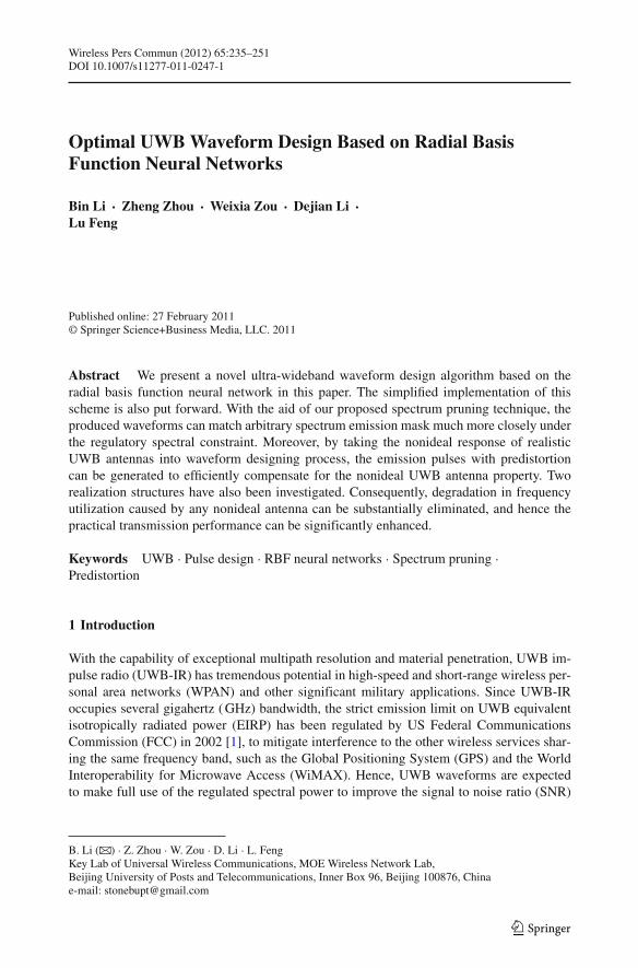
Fig. 1 Theoretical structure of UWB pulse design network. Note that the left feedback signal is used to updatenetwork parameters, while the right dotted error signal corresponds to the spectrum pruning process
been proposed as is illustrated in Fig. 1. By resorting to the excellent function approximationcapability of RBF networks [11], this scheme can produce UWB waveforms that fully matcharbitrary emission masks. The corresponding theoretical structure is described in detail asfollows:
2.1 Transform Module
Firstly, a group of radius basis functions is required before we can further elaborate the otherparts of this neural network. The transform modules Ti , in Fig. 1, mainly implement this func-tion, which in practice can be realized by a group of finite impulse response (FIR) filters orthe other analog devices. Considering the built-in mechanism of RBF, these modules shouldcontain some tunable parameters to adjust the widths and the centers of the correspondingbasis functions pi (k). In our following analysis, the common Gaussian function serves asthe basis waveform given its straightforward implementation.
⎧⎨
⎩
p0(k) = 1 k = 0, 1, . . . , N − 1
pi (k) = 1√2πsi
exp
(
− f 2s
2s2i(k − μi )
2)
k = 0, 1, . . . , N − 1 and i �= 0(2)
It is noteworthy that, from (2), p0(k) represents the network bias [11]. pi (k)(i = 1, 2, . . . , n)
denote the discrete radial basis functions with transform parameters μi and si , by which thewidths and centers of pi (k) can be flexibly adjusted.
Although the standard Gaussian function has been adopted as the RBF basis in our analy-sis, nevertheless, it is noteworthy that other functions still can be suggested according to theclassical Micchelli’s theory [11]. Specifically, for the other basis function candidates, theyshould ensure the localization property firstly, which means limr→∞ p(r) → 0. Meanwhile,these basis functions are supposed to be even symmetry, e.g. p(−r) = p(r) [11]. Conse-quently, as is reported by [13], the common inverse multiquadrics function [11], the raisedcosine function as well as the exponent function can be also employed in our RBF basedsignal generator.
For elaboration simplicity, we denote the vector composed of N samples of pi (k) by pi .Then, the equivalent input matrix of this whole neural net can be constructed from n radialbasis functions (notice that p0 is a constant):
P = [p0 p1 p2 . . . pn−1 pn]T (3)
123
238 B. Li et al.
2.2 Network Target
In this paper, our scheme designs the UWB waveform directly in frequency domain, whichmay be much more competitive from the aspect of its substantivity of optimizing the NESP.Thus, the network target should endeavor to match the UWB regulatory emission mask assoon as possible. If the UWB emission antenna is taken into account, then the target vectort can be determined both by FCC spectral constraint MFCC( f ) and the realistic antennaresponse:
t =√
Mtmp( f )/A( f )
∣∣∣
f =k fsk = 0, 1, . . . , N − 1 (4)
where fs represents the samples interval in frequency domain; the temporary pruned spec-trum mask Mtmp( f ), whose square root is exactly the Fourier transform of the designedUWB waveform, can be initiated by MFCC( f ).
In fact, the nonlinear antenna property may involve the spatial characteristics (e.g. angleof arrival, AOA) and the frequency response. In this paper, nevertheless, we only focus onthe nonideal frequency response of UWB antennas. Accordingly, A( f ) mainly accounts forthe antenna frequency response which is actually the magnitude response since the UWBantenna phase is inessential while considering the NESP.
2.3 Updating Algorithm
The mean square error (MSE), between the network output a and expected target t, can bedefined as:
E = 1
2‖a − t‖2 = 1
2
N−1∑
k=0
n∑
i=0
[w(i)pi (k) − t (k)]2 (5)
where the coefficient 1/2 is just for formulation simplicity. With the purpose of minimizingthe MSE between the actual output a and network target t, the network parameters, includingthe weight vector w and the transform parameters of basis functions pi (k), should be adap-tively updated according to certain rules. Specifically, the updating of the network weight wcan adopt the Windrow–Hoff rule [11]:
w(n) = w(n−1) + 2ξPe(n−1) (6)
where ξ is the updating step; w(n) represents the weight vector of the nth iteration. e(n−1)
denotes the error vector between network output a and the design target t. Then, the transformparameters can be updated according to the steepest descent algorithm based on (7) [11,13]:
∂ E
∂si=
N−1∑
k=0
n∑
i=0
{w(i) [w(i)pi (k) − t (k)]}∂pi
∂si
∂ E
∂μi=
N−1∑
k=0
n∑
i=0
{w(i) [w(i)pi (k) − t (k)]} ∂pi
∂μi
(7)
2.4 Spectrum Pruning
Concentrating on minimizing the MSE, this proposed RBF network may neglect the importantspectral constraint. Consequently, the derived power density spectrum S2( f ), correspondingto a2, may inevitably exceed MFCC( f ) in certain frequency bands, which may cause harmful
123
Optimal UWB Waveform Design Based on Radial Basis Function Neural Networks 239
interferences to the other vulnerable wireless systems [13,15]. Therefore, in practice, it isnecessary to carry out spectrum pruning after a round of network parameters updating. Con-ceptually, this spectrum pruning is rather intelligible. The actual network target Mtmp( f ) isjust a modification of the regulated emission limit MFCC( f ). By altering this network targetiteratively, at last, the designed UWB pulse matches the network target to the greatest extent.At the same time, this produced signal completely conforms to the spectrum constraint.
Observing that spectral mismatch always appears at the discontinuities and the deepestnotch, accordingly, we may prune the spectrum by smoothing the partial ranges with abruptedges. On the other hand, the modification of the emission mask is also supposed to beaccurate and modest on the premise of the final designed NESP.
⎧⎪⎪⎪⎪⎪⎨
⎪⎪⎪⎪⎪⎩
1)M (i)tmp( f ) = M (i−1)
tmp ( f ) − δ(i)1 × ( f − 0.7) f ∈ f−set1 : [0.70.9] GHz
2)M (i)tmp( f ) = M (i−1)
tmp ( f ) − δ(i)2 f ∈ f−set2 : [0.91.61] GHz
3)M (i)tmp( f ) = M (i−1)
tmp ( f ) − δ(i)3 × (1.81 − f ) f ∈ f−set3 : [1.61 1.81] GHz
4)M (i)tmp( f ) = M (i−1)
tmp ( f ) − δ(i)4 × (4.1 − f ) f ∈ f−set4 : [3.1 4.1] GHz
5)M (i)tmp( f ) = M (i−1)
tmp ( f ) − δ(i)5 × ( f − 9.6) f ∈ f−set5 : [9.6 10.6] GHz
(8)
where δi is the updating step; f _set i represents the corresponding frequency range that maycontain serious spectral mismatch. Rule 2 is mainly aimed at the narrow spectrum notchbelow 1.6 GHz, where the vibration results in the remarkable spectral excess; the other mod-ification rules correspond to these sharp discontinuous edges in original FCC mask, wherethe analogous Gibbs’ phenomenon always leads to obvious spectrum outstripping. In orderto minimize unfavorable influence on NESP, furthermore, the updating step δi should beconservatively changed
δ(k)i = δ
(k−1)i + ζi × max
[(S(k−1)( f )
)2 − MFCC( f )
]
( f ∈ f−seti , i = 1, 2, 3, 4, 5) (9)
where ζi is the decline rate of δi . The superscript k accounts for the moment after the kth
round updating of weight vector w and the transform parameters.It is worthwhile to emphasize that the pruned spectrum Mtmp( f ) should be applied to the
design target t during the next round of updating. This spectrum pruning process is termi-nated once S2( f )− MFCC( f ) has been reduced to an acceptable threshold, such as 0.1 dBm.Hence, the complete algorithm of our RBF scheme can be stated as follows:
Step 1 Initialize the RBF network target, Mtmp( f ), by using the FCC spectral constraintMFCC( f ).
Step 2 Initialize the network parameters, including the transform parameters (μi and si )and the network weights w.
Step 3 Evaluate the spectral matching error E of RBF networks. If E is less than a prede-termined threshold, then the network parameters updating is finished, and go to Step6; otherwise, continue to the next step.
Step 4 Update the network weight w according to (6), and then alter the transform param-eters μi and si based on (7).
Step 5 Return to Step 3, and repeat above steps.Step 6 Compute the network output S2( f ) and compare it with the FCC spectrum mask
MFCC( f ). If S2( f ) − MFCC( f ) is less than 0.1 dBm, go to Step 9; otherwise, con-tinue the next step.
Step 7 Modify the updating rate of the spectrum pruning according to (9). Then, obtain thepruned spectrum from (8) and renew the temporary design target t.
123
240 B. Li et al.
Step 8 Return to Step 2. Start another round of RBF network updating.Step 9 Save the network parameters, and begin to generate the optimized UWB pulse.
2.5 Algorithm Simplification
Given that the UWB spectrum mask remains flat in most frequency band, the width of basisfunctions pi (k) tend to be equal to each other, and their centers would be uniformly locatedat the frequency axis when n is large enough. Therefore, the transform parameters will bereduced to a single one, which only determines the width of the unique basis function popt (k).Furthermore, the complexity of iterative updating algorithm will be reduced if the uniqueoptimum parameter sopt has been attained beforehand [13]. In consequence, the unique opti-
mum basis function popt (k) can be given by 1/(√
2πsopt
)× exp
[−(k fs)
2/(2s2opt )
], and
hence pi (k) can be derived by
pi (k)=popt
(
k − (i − 1)N
n2
)
= 1√2πsopt
exp
{− f 2
s
2s2opt
(
k − (i − 1)N
n2
)2}
i=1, . . . , n2
(10)
In such a case, only the weight vector w needs adjusting in the network updating stage.Accordingly, the algorithm complexity is greatly reduced. Meanwhile, the realization ofUWB pulses has also been simplified considerably. It is noteworthy that the feasibility valuefor sopt should take the realistic spectral limits into consideration [13].
2.6 UWB Pulse Generation
According to the Micchelli’s theory, the network weight vector w is destined to converge tothe Wiener optimal value wopt [11]. When n is equal to N , wopt can be given by:
wopt = �−1t (11)
where the elements of matrix � is obtained from popt (k):
ϕnm = pm(n) (12)
To further simplify realizations, n is always smaller than N in practice. Then, wopt can berewritten as:
wopt = (�T �)−1�T t (13)
After the pruned spectrum Mtmp( f ) and the network weight w have both converged to theirstationary value, the UWB pulse can be obtained immediately by inverse discrete Fouriertransform (IDFT) on the actual output a:
s(n) = IDFT (〈exp(− j2π�) ⊗ a〉) = IDFT(⟨
exp(− j2π�) ⊗ purelin(wTopt P)
⟩)
(14)
where purelin(.) represents the transfer function of the RBF neural network [11]; 〈z〉 denotesthe even component constructed from z [12,13]. � is the user defined phase response, thenotation ⊗ represents the multiplication of corresponding elements between two vectorswith the same dimension. If the UWB antenna phase is denoted by �, furthermore, we maycontain the nonlinear phase of UWB antenna into �. Thus, the phase vector in (14) shouldbe rewritten as � − �.
123
Optimal UWB Waveform Design Based on Radial Basis Function Neural Networks 241
2.7 Integrating Nonlinear Antenna into RBF
In fact, the above presented waveform design formulation can be essentially viewed as aclassical mathematical function interpolation problem. Attributed to the excellent functionapproximation capability of RBFs, this UWB waveform generator can always produce com-petitive emission pulses, in consideration of matching the specified spectrum shape [11,13].On the other hand, as is indicated by the implementation paradigm in [3,5], during cer-tain realistic operation scenarios such as in the presence of multipath channel propagationsand nonlinear UWB antennas, the front-end response can be also integrated into the analogfunction implementation alternatively. Indeed, the similar strategy can be also introducedto our RBF architecture to considerably simplify the network updating algorithm given thespecific UWB emission constraints, since further weighting vector modification can be basi-cally avoided when the realistic operation environment changes (e.g., only alters the basisfunctions).
In practice, the realization of RBFNN, by considering the nonlinear antennas, is quitedifferent from the adopted scheme in [3,5]. The UWB pulse shaper proposed in ref. [5] isdirectly realized in the time domain, which involves a FIR filter h(t) cascaded to a analoglinear time invariant system (LTI) denoted by g(t). As a consequence, according to the asso-ciative law of convolution process, the nonideal response, a(t), can be then convenientlyintegrated into g(t), that is, h(t)∗g(t)∗a(t) = h(t)∗{g(t)∗a(t)} [5]. Nevertheless, given theRBF inspired waveform generator mainly focus on the frequency domain; the correspondingimplementation architecture may take on somewhat dissimilar arrangements.
For facilitating the following elaborations, we adopt the simplified RBFNN algorithmand assume that the optimal width of each basis function has been pre-specified [13]. Wefurther represent each basis function, pi (k)(i = 1, 2, . . ., n), by M non-zero samples withthe corresponding center located at (i − 1)N/n. Unlike the time domain technique, we haveto modify the traditional RBF architecture in order to take the nonideal antenna response intoaccount from the frequency domain. To attain this goal, the basis functions in our new schemeare no longer the standard Gaussian functions, but a group of modified basis waveforms asis expressed by (15) based on the realistic antenna A( f )
gi (k) = pi (k)
A(k) × WM
(k − (i−1)N
n
) , i = 1, 2, . . . , n (15)
Here, WM (k − k0) represents one rectangle window function with a width of M samplesand a center of k0. Based on this group of generalized basis functions gi (k), we may furtherderive the output of this new waveform generator. If the optimal weight w under the emissionmask S(k) has been achieved, given a nonideal UWB antenna A(k), we may have:
n∑
i=1
w(i)gi (k) =n∑
i=1
w(i)pi (k)
A (k) × WM
(k − (i−1)N
n
)
=n∑
i=1
w(i)pi (k)
A(k)= S(k)
/
A(k) (16)
From (16), it is apparent that, in this new framework, the realistic nonideal transmitterresponse G(k) can be also compensated entirely by the well-designed basis functions in(15). Meanwhile, the weight vector w may need no further modification for a new encoun-tered UWB antenna, resulting in a simplified algorithm. Actually, this presented network can
123
242 B. Li et al.
0.5 1 1.5 2 2.5 30
0.1
0.2
0.3
0.4
0.5
0.6
0.7
0.8
0.9
1
Frequency /GHz
Am
plitu
de
Gaussian basis function
Generalized basis function
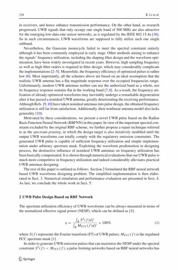
Fig. 2 Generalized basis function by taking consideration of the realistic front-end response
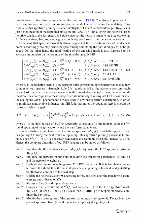
be regarded as a generalized RBF neural networks (GRBFNN), in which the basis functionsmay keep different from each other in widths, centers as well as shapes, due to the non-flatfrequency response of realistic environments. Figure 2 also picks up one Gaussian basis andthe corresponding generalized basis waveform derived from (15). Given a nonideal antennaresponse, for example, the calculated cross correlation between these two basis functions isabout 0.9.
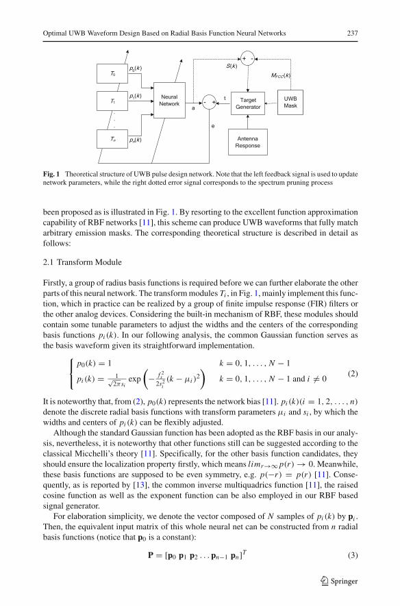
3 Implementation
The implementation structure of our proposed UWB waveform has been shown in Fig. 3,which is based on the simplified traditional RBF architecture. Firstly, an impulse sequencewith a period of N samples is generated at a sampling frequency of 25 GHz. Then, the uniquebasis function popt (k) is formed after this impulse sequence has passed a Gaussian filter witha specific time-bandwidth products BT which is determined by
√ln 2/2πsopt . Subsequently,
pi can be easily obtained after the (i − 1) × l samples delaying has been performed onpopt (k), where l represents the delay factor, and the input matrix P is composed of �N/ l basis functions pi . The network weight w is then adaptively altered according to (6). After around of updating, w may converge to its optimum value, and then a temporary UWB pulsecan be generated. The network target Mtmp( f ) is pruned and then employed in the next roundnetwork updating.
From the structure of pulse generator illustrated in Fig. 3, the basis function popt (k) alsoshows periodicity in consideration of the input periodical impulse sequence. Thus, the sam-ples delay operation is equivalent to the cyclical shift on popt (k). If the cyclical shift propertyof DFT is applied [12], then the time domain pulse is further written as:
s(n) = Re
{1
N
n∑
i=0
w(i)p′(m) exp
(
−j2π
Nmil
)}
(17)
where p′(n) denotes the IDFT of popt (k).
123
Optimal UWB Waveform Design Based on Radial Basis Function Neural Networks 243
z-1
1 +
+
+
+
w (0) w(1) w (2) w(n)
z-nl
~
np
~
2p
~
1p
.
.
. e
TargetGenerator
|·|2
Transform IFFT
Spectrum
Mask
AntennaRespons
e
+ -
A(k)a
t
~
0p
Gaussian
+ -
+
outputs(n)
S2(k)
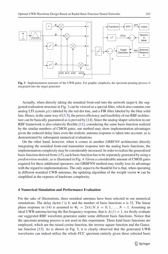
Fig. 3 Implementation structure of the UWB pulse. For graphic simplicity, the spectrum pruning process isintegrated into the target generator
Actually, when directly taking the nonideal front-end into the network target t, the sug-gested realization structure in Fig. 3 can be viewed as a special filter, which also contains oneanalog LTI system g(t) labeled by the red dot line, and a FIR filter labeled by the blue solidline. Hence, in the same way of [3,5], the power efficiency and feasibility of our RBF architec-ture can be basically guaranteed as is proved by [14]. Since the analog shaper selection in ourRBF framework is also relatively flexible [11], considering the same basis function realizedby the similar numbers of CMOS gates, our method may show implementation advantagesgiven the reduced delay lines even the realistic antenna response is taken into account, as isdemonstrated by subsequent numerical evaluations.
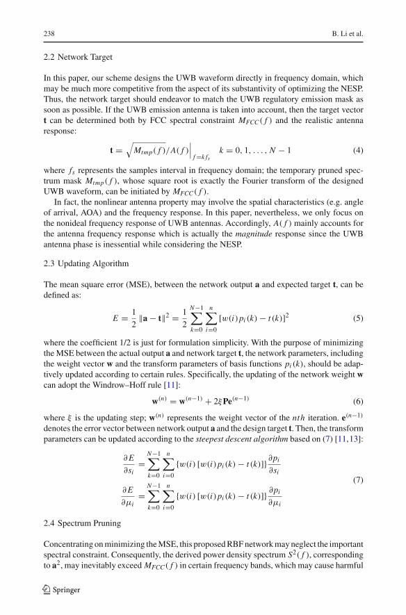
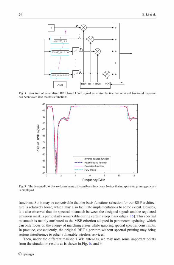
On the other hand, however, when it comes to another GRBFNN architecture directlyintegrating the nonideal front-end transmitter response into the analog basis functions, theimplementation complexity may be considerably increased. In order to realize the generalizedbasis function derived from (15), each basis function has to be separately generated by using apredistortion module, as is illustrated in Fig. 4. Given a considerable amount of CMOS gatesrequired for these additional operators, our GRBFNN method may totally lose its advantagewith the regard to implementations. The only aspect to be thankful for is that, when operatingin different nonideal UWB antennas, the updating algorithm of the weight vector w can besimplified at the expense of hardware complexity.
4 Numerical Simulation and Performance Evaluation
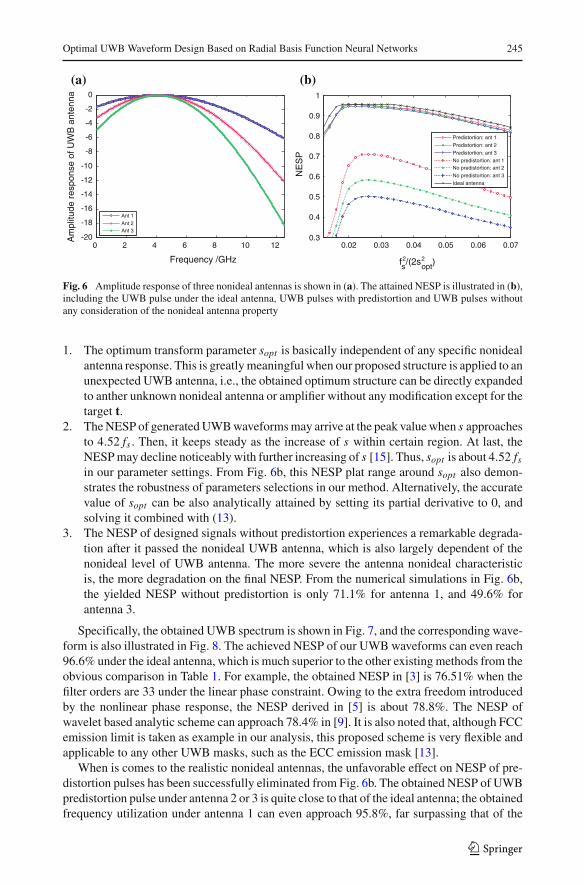
For the sake of illustrations, three nonideal antennas have been selected in our numericalsimulations. The delay factor l is 8, and the number of basis functions n is 32. The linearphase response in (14) is assumed to k = 2πk/N , k = 0, 1, . . . , N − 1. Assuming anideal UWB antenna having the flat frequency response, that is A( f ) = 1, we firstly evaluateour suggested RBF waveform generator under some different basis functions. Notice thatthe spectrum pruning process is not used in this experiment. Three kind basis functions areemployed, which are the raised cosine function, the inverse square function and the Gauss-ian function [13]. As is shown in Fig. 5, it is clearly observed that the generated UWBwaveforms can indeed utilize the whole FCC spectrum entirely given these selected basis
123
244 B. Li et al.
z-1
1 +
+
+
+
w(0) w(1) w(2) w(n)
z-nl
~
np
~
2p
~
1p
.
.
.
e
~
0p
+
A(k )
( )1
( )M
A k W k×
( )1
( ) /M
A k W k N n× −
( )( )
1
( ) 1 /M
A k W k n N n− −
.
.
.
Fig. 4 Structure of generalized RBF based UWB signal generator. Notice that nonideal front-end responsehas been taken into the basis functions
0 2 4 6 8 10 12-95
-90
-85
-80
-75
-70
-65
-60
-55
-50
-45
-40
Frequency/GHz
PS
D o
f UW
B s
igna
l
Inverse square function
Raise cosine function
Gaussian function
FCC mask
Fig. 5 The designed UWB waveforms using different basis functions. Notice that no spectrum pruning processis employed
functions. So, it may be conceivable that the basis functions selection for our RBF architec-ture is relatively loose, which may also facilitate implementations to some extent. Besides,it is also observed that the spectral mismatch between the designed signals and the regulatedemission mask is particularly remarkable during certain steep mask edges [15]. This spectralmismatch is mainly attributed to the MSE criterion adopted in parameters updating, whichcan only focus on the energy of matching errors while ignoring special spectral constraints.In practice, consequently, the original RBF algorithm without spectral pruning may bringserious interference to other vulnerable wireless services.
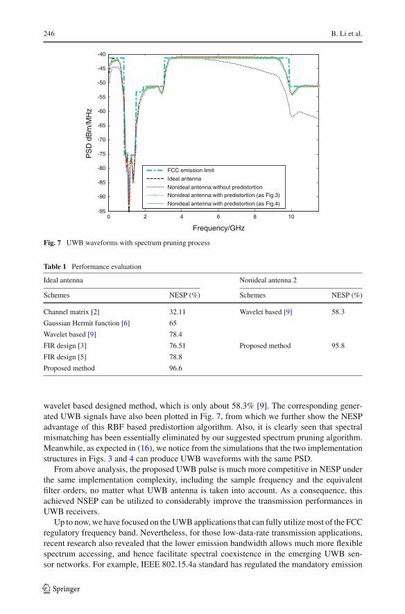
Then, under the different realistic UWB antennas, we may note some important pointsfrom the simulation results as is shown in Fig. 6a and b:
123
Optimal UWB Waveform Design Based on Radial Basis Function Neural Networks 245
0 2 4 6 8 10 12-20
-18
-16
-14
-12
-10
-8
-6
-4
-2
0
Frequency /GHz
Am
plitu
de r
espo
nse
of U
WB
ant
enna
Ant 1
Ant 2Ant 3
0.02 0.03 0.04 0.05 0.06 0.070.3
0.4
0.5
0.6
0.7
0.8
0.9
1
fs2/(2sopt
2 )
NE
SP
Predistortion: ant 1
Predistortion: ant 2
Predistortion: ant 3
No predistortion: ant 1No predistortion: ant 2
No predistortion: ant 3
Ideal antenna
(a) (b)
Fig. 6 Amplitude response of three nonideal antennas is shown in (a). The attained NESP is illustrated in (b),including the UWB pulse under the ideal antenna, UWB pulses with predistortion and UWB pulses withoutany consideration of the nonideal antenna property
1. The optimum transform parameter sopt is basically independent of any specific nonidealantenna response. This is greatly meaningful when our proposed structure is applied to anunexpected UWB antenna, i.e., the obtained optimum structure can be directly expandedto anther unknown nonideal antenna or amplifier without any modification except for thetarget t.
2. The NESP of generated UWB waveforms may arrive at the peak value when s approachesto 4.52 fs . Then, it keeps steady as the increase of s within certain region. At last, theNESP may decline noticeably with further increasing of s [15]. Thus, sopt is about 4.52 fs
in our parameter settings. From Fig. 6b, this NESP plat range around sopt also demon-strates the robustness of parameters selections in our method. Alternatively, the accuratevalue of sopt can be also analytically attained by setting its partial derivative to 0, andsolving it combined with (13).
3. The NESP of designed signals without predistortion experiences a remarkable degrada-tion after it passed the nonideal UWB antenna, which is also largely dependent of thenonideal level of UWB antenna. The more severe the antenna nonideal characteristicis, the more degradation on the final NESP. From the numerical simulations in Fig. 6b,the yielded NESP without predistortion is only 71.1% for antenna 1, and 49.6% forantenna 3.
Specifically, the obtained UWB spectrum is shown in Fig. 7, and the corresponding wave-form is also illustrated in Fig. 8. The achieved NESP of our UWB waveforms can even reach96.6% under the ideal antenna, which is much superior to the other existing methods from theobvious comparison in Table 1. For example, the obtained NESP in [3] is 76.51% when thefilter orders are 33 under the linear phase constraint. Owing to the extra freedom introducedby the nonlinear phase response, the NESP derived in [5] is about 78.8%. The NESP ofwavelet based analytic scheme can approach 78.4% in [9]. It is also noted that, although FCCemission limit is taken as example in our analysis, this proposed scheme is very flexible andapplicable to any other UWB masks, such as the ECC emission mask [13].
When is comes to the realistic nonideal antennas, the unfavorable effect on NESP of pre-distortion pulses has been successfully eliminated from Fig. 6b. The obtained NESP of UWBpredistortion pulse under antenna 2 or 3 is quite close to that of the ideal antenna; the obtainedfrequency utilization under antenna 1 can even approach 95.8%, far surpassing that of the
123
246 B. Li et al.
0 2 4 6 8 10-95
-90
-85
-80
-75
-70
-65
-60
-55
-50
-45
-40
Frequency/GHz
PS
D d
Bm
/MH
z
FCC emission limit
Ideal antenna
Nonideal antenna:without predistortionNonideal antenna:with predistortion (as Fig.3)
Nonideal antenna:with predistortion (as Fig.4)
Fig. 7 UWB waveforms with spectrum pruning process
Table 1 Performance evaluation
Ideal antenna Nonideal antenna 2
Schemes NESP (%) Schemes NESP (%)
Channel matrix [2] 32.11 Wavelet based [9] 58.3
Gaussian Hermit function [6] 65
Wavelet based [9] 78.4
FIR design [3] 76.51 Proposed method 95.8
FIR design [5] 78.8
Proposed method 96.6
wavelet based designed method, which is only about 58.3% [9]. The corresponding gener-ated UWB signals have also been plotted in Fig. 7, from which we further show the NESPadvantage of this RBF based predistortion algorithm. Also, it is clearly seen that spectralmismatching has been essentially eliminated by our suggested spectrum pruning algorithm.Meanwhile, as expected in (16), we notice from the simulations that the two implementationstructures in Figs. 3 and 4 can produce UWB waveforms with the same PSD.
From above analysis, the proposed UWB pulse is much more competitive in NESP underthe same implementation complexity, including the sample frequency and the equivalentfilter orders, no matter what UWB antenna is taken into account. As a consequence, thisachieved NSEP can be utilized to considerably improve the transmission performances inUWB receivers.
Up to now, we have focused on the UWB applications that can fully utilize most of the FCCregulatory frequency band. Nevertheless, for those low-data-rate transmission applications,recent research also revealed that the lower emission bandwidth allows much more flexiblespectrum accessing, and hence facilitate spectral coexistence in the emerging UWB sen-sor networks. For example, IEEE 802.15.4a standard has regulated the mandatory emission
123
Optimal UWB Waveform Design Based on Radial Basis Function Neural Networks 247
3.5 4 4.5 5 5.5 6 6.5 7
x 10-9
-0.1
-0.05
0
0.05
0.1
0.15
0.2
0.25
0.3
Time /sec
Mag
nitu
de /v
olt
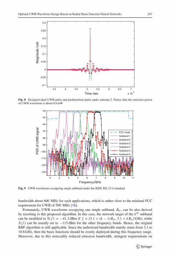
Fig. 8 Designed ideal UWB pulse and predistortion pulse under antenna 2. Notice that the emission powerof UWB waveform is about 0.6 mW
2 3 4 5 6 7 8 9 10 11
-130
-120
-110
-100
-90
-80
-70
-60
-50
-40
Frequency/GHz
PS
D o
f UW
B s
igna
l
FCC mask
Subband 1
Subband 2
Subband 3
Subband 4
Subband 5
Subband 6
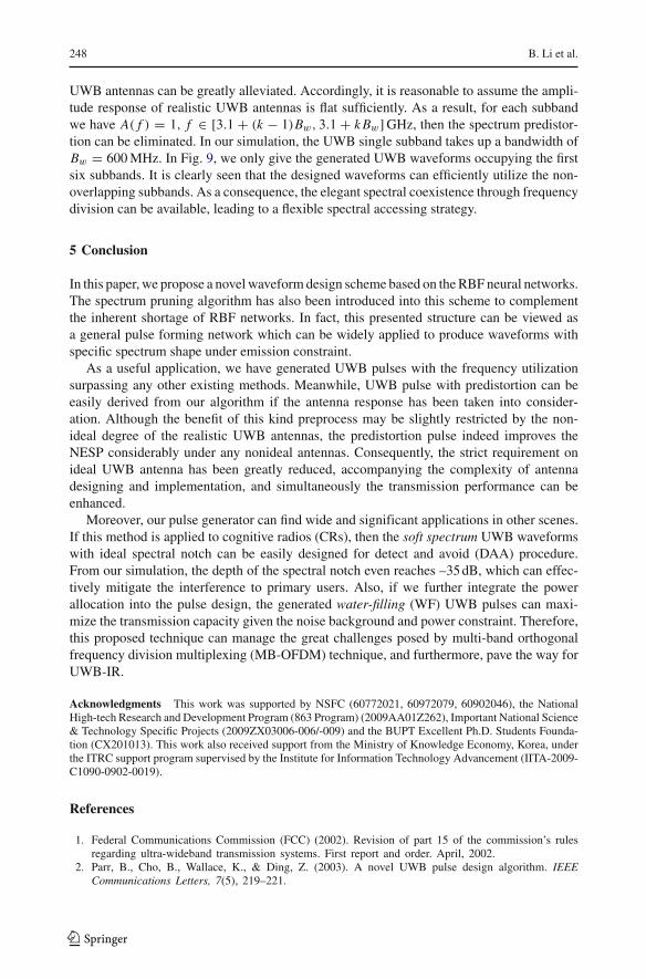
Fig. 9 UWB waveforms occupying single subband under the IEEE 802.15.4 standard
bandwidth about 600 MHz for such applications, which is rather close to the minimal FCCrequirement for UWB of 500 MHz [16].
Fortunately, UWB waveforms occupying one single subband, Bw , can be also derivedby resorting to this proposed algorithm. In this case, the network target of the kth subbandcan be modified to S( f ) = −41.3 dBm if f ∈ [3.1 + (k − 1)Bw, 3.1 + k Bw] GHz; whileS( f ) can be usually set to −115 dBm for the other frequency bands. Hence, the originalRBF algorithm is still applicable. Since the authorized bandwidth mainly starts from 3.1 to10.6 GHz, then the basis functions should be evenly deployed during this frequency range.Moreover, due to this noticeably reduced emission bandwidth, stringent requirements on
123
248 B. Li et al.
UWB antennas can be greatly alleviated. Accordingly, it is reasonable to assume the ampli-tude response of realistic UWB antennas is flat sufficiently. As a result, for each subbandwe have A( f ) = 1, f ∈ [3.1 + (k − 1)Bw, 3.1 + k Bw] GHz, then the spectrum predistor-tion can be eliminated. In our simulation, the UWB single subband takes up a bandwidth ofBw = 600 MHz. In Fig. 9, we only give the generated UWB waveforms occupying the firstsix subbands. It is clearly seen that the designed waveforms can efficiently utilize the non-overlapping subbands. As a consequence, the elegant spectral coexistence through frequencydivision can be available, leading to a flexible spectral accessing strategy.
5 Conclusion
In this paper, we propose a novel waveform design scheme based on the RBF neural networks.The spectrum pruning algorithm has also been introduced into this scheme to complementthe inherent shortage of RBF networks. In fact, this presented structure can be viewed asa general pulse forming network which can be widely applied to produce waveforms withspecific spectrum shape under emission constraint.
As a useful application, we have generated UWB pulses with the frequency utilizationsurpassing any other existing methods. Meanwhile, UWB pulse with predistortion can beeasily derived from our algorithm if the antenna response has been taken into consider-ation. Although the benefit of this kind preprocess may be slightly restricted by the non-ideal degree of the realistic UWB antennas, the predistortion pulse indeed improves theNESP considerably under any nonideal antennas. Consequently, the strict requirement onideal UWB antenna has been greatly reduced, accompanying the complexity of antennadesigning and implementation, and simultaneously the transmission performance can beenhanced.
Moreover, our pulse generator can find wide and significant applications in other scenes.If this method is applied to cognitive radios (CRs), then the soft spectrum UWB waveformswith ideal spectral notch can be easily designed for detect and avoid (DAA) procedure.From our simulation, the depth of the spectral notch even reaches –35 dB, which can effec-tively mitigate the interference to primary users. Also, if we further integrate the powerallocation into the pulse design, the generated water-filling (WF) UWB pulses can maxi-mize the transmission capacity given the noise background and power constraint. Therefore,this proposed technique can manage the great challenges posed by multi-band orthogonalfrequency division multiplexing (MB-OFDM) technique, and furthermore, pave the way forUWB-IR.
Acknowledgments This work was supported by NSFC (60772021, 60972079, 60902046), the NationalHigh-tech Research and Development Program (863 Program) (2009AA01Z262), Important National Science& Technology Specific Projects (2009ZX03006-006/-009) and the BUPT Excellent Ph.D. Students Founda-tion (CX201013). This work also received support from the Ministry of Knowledge Economy, Korea, underthe ITRC support program supervised by the Institute for Information Technology Advancement (IITA-2009-C1090-0902-0019).
References
1. Federal Communications Commission (FCC) (2002). Revision of part 15 of the commission’s rulesregarding ultra-wideband transmission systems. First report and order. April, 2002.
2. Parr, B., Cho, B., Wallace, K., & Ding, Z. (2003). A novel UWB pulse design algorithm. IEEECommunications Letters, 7(5), 219–221.
123
Optimal UWB Waveform Design Based on Radial Basis Function Neural Networks 249
3. Wu, X., Tian, Z., Davidson, T. N., & Giannakis, G. B. (June 2006). Optimal waveform design forUWB radios. IEEE Transaction on signal processing, 54(6), 2009–2021.
4. Davidson, T. N., Luo, Z. Q., & Sturm, J. F. (2002). Linear matrix inequality formulation of spectralmask constraints with applications to FIR filter design. IEEE Transactions on Signal Process-ing, 50(11), 2702–2715.
5. Dotlic, I., & Kohno, R. (2007). Design of the family of orthogonal and spectrally efficient UWBwaveforms. IEEE Journal of Selected Topics in Signal Processing, 1(1), 21–30.
6. Yang, R., et al. (2008). Detection and avoidance scheme for DS-UWB system: A step towardscognitive radio. IEE Proceedings Communications, 2(8), 1043–1050.
7. Evangelos, S. A., & Anastopoulos, A. Z., et al. (2006). Circular and elliptical CPW-Fed slot andmicro strip-fed antennas for ultra wideband applications. IEEE Antennas and Wireless PropagationLetters, 5, 294–297.
8. Lu, G. F., Spasojevic, P., & Greenstein, L. (2003). Antenna and pulse designs for meeting UWBspectrum density requirements. In IEEE conference on ultra wideband systems and technologies, (pp.162–166) Reston: Piscataway.
9. Wu, X., Sha, X., & Zhang, N. (2007). Pulse shaping method to compensate for antenna distortion inultra-wideband communications. Science in China Series F: Information Sciences, 50(6), 878–888.
10. Abreu, G. H. F., Mitchell, C. J., & Kohno, R. (2003). On the design on orthogonal pulse shapemodulation for UWB systems using hermite pulses. Journal of Communication Networks, 5(4), 328–343.
11. Haykin, S. (1998). Neural networks, a comprehensive foundation, 2nd edn. New Jersey: Prentice Hall.12. Oppenheim, A. V., Nawab, S., Nawab, S. H., & Willsky, A. S. (1996). Signals and systems.
New Jersey: Prentice Hall.13. Li, B., Zhou, Z., & Zou, W. (Sept 2009). A novel spectrum adaptive UWB pulse: Application in
cognitive radio. In Proceedings of IEEE vehicular technology conference (VTC Fall 2009), (pp. 1–5),Anchorage, Alaska, USA.
14. Lachartre, D., Denis, B., Morche, D., Ouvry, L., Pezzin, M., Piaget, B., et al. (2009). A 1.1nJ/b802.15.4a compliant fully integrated UWB transceiver in 0.13μm CMOS. In IEEE internationalsolid-state circuits conference digest of technical papers (ISSCC ‘09), (pp. 312–313a).
15. Li, B., Zhou, Z., & Zou, W. (2010). A novel adaptive spectrum forming filter: Application in thecognitive ultra-wideband. Science China Information Sciences, 53(12), 2584–2599.
16. IEEE Standard 802.15.4-2006, Part 15.4: Wireless medium access control (MAC) and physical layer(PHY) specifications for low-rate wireless personal area networks (LR-WPANs), 2006.
Author Biographies
Bin Li received his master degree of Communication and Informa-tion Engineering of Beijing University of Posts & Telecommunications(BUPT) in 2009. He is now a Ph.D. student with the Key Lab of Uni-versal Wireless Communications (MOE), and the Wireless NetworkingLab of BUPT. His current interesting areas focus on bio-inspired intel-ligent algorithm, signal processing for ultra-wideband (UWB), wirelesssensor network (WSN) and cognitive radios (CRs).
123
250 B. Li et al.
Zheng Zhou received his bachelor degree from the Harbin Instituteof Military Engineering in 1967, and his master of Electrical Engi-neering in Beijing University of Posts & Telecommunications (BUPT)in 1982, and Electrical Engineering Ph.D. degree from Beijing Uni-versity of Posts & Telecommunications in 1988. At present, he is aProfessor in Beijing University of Posts & Telecommunications Bei-jing, China. Supported by the Hong Kong Telecom International Post-doctoral Fellowship, Professor Zhou was a Visiting Research Fellowin Information Engineering Department of the Chinese University ofHong Kong, Hong Kong from 1993 to 1995. He is also the Vice-Deanin School of Telecommunication Engineering of BUPT from 1998to 2003, and the Invited Overseas Researcher in Japan Kyocera DDIFuture Communication Research Institute (supported by the Japan KeyTechnology Center) in 2000. Professor Zhou serves as a member ofTechnical Sub-committee on Cognitive Networks (TCCN), IEEE Com-munications Society, the International Steering Committee Member of
IEEE ISCIT 2003–2008 (International Symposium on Communications and Information Technologies), andthe TPC Co-Chairs of IEEE ISCIT 2005. He is also the General Vice Chairs of IEEE ChinaCom 2006 (theFirst International Conference on Communications and Networking in China), and the Steering CommitteeMember of IEEE ChinaCom 2007. Professor Zhou is the Voting Member and Contributor of IEEE 802.15Task Group (TG3a & TG4a), the Member of IEEE, Senior Member of China Institution of Communica-tions (CIC), Radio Application and Management Technical Committee Member of CIC, Senior Member ofChina Computer Federation (CCF), Sensor Network Technical Committee Member of CCF, H subcommit-tee Member of China Radio Interference Standard Technology Committee, the General Secretary of ChinaUWB Forum and the General Secretary of China Bluetooth Forum.
Weixia Zou received her bachelor degree in Tongji University in 1994,master degree in Shandong University in 2002, and Ph.D. degree fromBeijing University of Posts and Telecommunications in 2006. She isnow an associate professor of Key Lab of the ubiquitous wireless, Min-istry of Education (MOE). Her current research focused on new tech-nology of short-range wireless communication and EMC.
Dejian Li received the B.S. degree in electrical engineering from theHebei University of Technology, Tianjin, P.R.C., in 2006. He is cur-rently working toward the Ph.D. degree in communication engineeringfrom the Beijing University of Posts and Telecommunications, Beijing,P.R.C. His professional interests include the theory and application ofcompressed sensing, radio propagation measurement and modeling ofUWB.
123
Optimal UWB Waveform Design Based on Radial Basis Function Neural Networks 251
Lu Feng is now a Master candidate in the Key Lab of Universal Wire-less Communications (MOE), and the Wireless Networking Lab of Bei-jing University of Posts & Telecommunications (BUPT). Her currentresearch interests include ultra-wideband (UWB) and cognitive radios(CRs).
123