ds-pam uwb system using non-linear chirp waveform
TRANSCRIPT

We propose a direct-sequence pulse-amplitude modulation (DS-PAM) ultra-wideband (UWB) system which employs a non-linear chirp waveform instead of the conventional Gaussian monocycle in this paper. In the approved frequency for UWB, there exist myriad narrowband interferers. Specifically, we focus on the mutual interference between UWB systems and 802.11a WLAN. This paper offers a method to suppress this in-band narrowband interference by introducing a kind of non-linear chirp waveform. Using the proposed non-linear chirp waveform, the effects of one or more narrowband interference sources with different frequencies can be suppressed. System performance of UWB systems in the narrowband interference environment can be improved. Computer simulations with additive white Gaussian noise successfully demonstrate an increase in performance with the proposed system as compared to traditional linear chirp systems.
Keywords: Ultra-wideband (UWB), non-linear chirp, narrowband interference (NBI).
Manuscript received Oct. 17, 2006; revised Feb. 20, 2007. This research was supported by the MIC (Ministry of Information and Communication),
Korea, under the ITRC (Information Technology Research Center) support program supervised by the IITA (Institute of Information Technology Advancement) (IITA-2006-(C1090-0603-0019)).
Hanbing Shen (phone: + 82 32 864 8935, email: [email protected]), Weihua Zhang (email: [email protected]), Xizhi An (email: [email protected]), and Kyung Sup Kwak (email: [email protected]) are with Graduate School of IT&T, Inha University, Incheon, Korea.
I. Introduction
Recently, ultra-wideband (UWB) has gained considerable research interest since the FCC approved a frequency limit for UWB technology. The FCC allows occupation of an ultra-wide frequency band from 3.1 GHz to 10.6 GHz with a power spectral density of less than -41.3 dBm/MHz [1].
Existing UWB systems are based on two main kinds of waveform modulation schemes: pulsed waveform and chirp. Both schemes have their own advantages and shortcomings. Different waveforms have been previously studied in pulsed UWB schemes, including Gaussian pulse series [2], [3] and Hermite pulse series [4], [5]. The pulsed scheme can be operated by simple transmitter with rich resolvable multipath components for multipath diversity reception in communication systems and fine time resolution for accurate position location in radar applications. However, pulsed UWB using extremely short time duration of time pulses with an extremely high peak-to-average ratio causes many hardware implementation problems. These include power amplifier nonlinearity when the system is designed to operate at low data rates but with a large frequency bandwidth. It also requires an extremely fast power rise time and low-noise amplifiers (LNA), which incur high costs at present [6]. Chirp waveform schemes have historically been used extensively in radar applications. Compared with pulsed schemes, chirp schemes can overcome their shortcomings. Using a long time duration modulation waveform without a high peak-to-average ratio, power amplifier nonlinearity in the system can be avoided. Low-cost and low-complexity hardware can be used in the LNA parts of an apparatus. Sometimes chirp wave signals are called continuous-waveform (CW) signals.
Because of the very short time windowing at the receiver and the high correlation of narrowband signals over a short
DS-PAM UWB System Using Non-linear Chirp Waveform
Hanbing Shen, Weihua Zhang, Xizhi An, and Kyung Sup Kwak
322 Hanbing Shen et al. ETRI Journal, Volume 29, Number 3, June 2007

time interval, UWB systems have inherent immunity to narrowband interference (NBI). Due to the low power spectral density, however, a high level of NBIs, as when there is an IEEE 802.11a wireless local area network (WLAN) device operating nearby, can still badly affect the system performance of UWB systems. It can even cause the UWB receiver be jammed if the interference is not properly suppressed [7].
Chirps have many desirable properties and are used in many applications, such as sonar and radar [8]. Chirp signals are spread spectrum signals [9]. The interference rejection property of chirp signals is inherently good. The utility of linear frequency chirp is superior to PSK and FSK in partially coherent and fading cases [10]. Chirp modulation in the high frequency (HF) band was introduced in an experimental communication system in [11]. Linear FM chirp signals have been proposed for UWB ranging systems, where chirp signals have the same time duration and different frequency bands [12].
This paper proposes a new non-linear chirp modulation system for UWB systems. Using non-linear chirp modulation, system performance under high level NBIs improves compared with linear chirp systems. The design of this NBI resistible non-linear chirp is described. The system performance, especially the bit error rate (BER) of linear chirps and the proposed non-linear ones are compared by computer simulation. The simulation results confirm that the proposed scheme outperforms the traditional linear schemes.
II. Background Introduction
1. Chirp Theory
A chirp waveform, as presented in [13], can be written as
)],(cos[)()( ttatc Θ= (1)
where Θ(t) is the phase, and a(t) is the envelope of the chirp signal, which is zero outside a time interval of length Ts. The instantaneous frequency is defined as
.)(21)(
dttdtfc
Θ=
π (2)
Chirp rate, an important parameter in chirp systems, is defined by
.)(21)(
)( 2
2
dttd
dttdf
t c Θ==
πμ (3)
It represents the rate of change of the instantaneous frequency. The chirp waveforms with μ(t) > 0 are called up-chirps and those with μ(t) < 0 are called down-chirps.
For a linear chirp system, μ(t) is constant; hence, fc(t) is a linear function of t, and Θ(t) is a quadratic function. If we define the linear chirp waveform to be centered at t = 0, it can be written as
c(t) = a(t) cos(2πf0t + πμt2 + φ0), (4)
where f0 is the center frequency and a(t) = 0 for |t| > Ts /2. The bandwidth B is conveniently defined as the range of the
instantaneous frequency so that
B = |μ| ·Ts . (5)
On the receiver side, a matched filter is used to demodulate the chirp waves, whose impulse response, hm(t), is given by
hm(t) = c *(−t), (6)
where * denotes the complex conjugate. The envelope of the chirp signal a(t) is often a constant value when |t|≤Ts/2. Without loss of generality, we can set a(t)=1 in the analysis. The output waveform g(t) of the matched filter is given by
)2cos(
1sin
)(*)()(
0tfBt
Tt
Bt
T
tcthtg
s
m
ππ
π⎥⎥⎦
⎤
⎢⎢⎣
⎡⎟⎟⎠
⎞⎜⎜⎝
⎛−
=
=
(7)
for |t| ≤ Ts.
2. Narrowband Interference (NBI)
In the approved frequency for UWB, there exist myriad potential interferers (licensed and unlicensed) operating in the spectrum allotted to UWB. Compared with the ultra-wide bandwidth of UWB systems (3.1 GHz to 10.6 GHz of the main spectrum band), all these interferers can be treated as narrowband interference sources. For example, WLAN devices using the IEEE 802.11a standard operate in the 5 GHz Unlicensed National Information Infrastructure (U-NII) frequency bands. Three 100-MHz-wide frequency bands (5.15 to 5.25, 5.25 to 5.35, and 5.725 to 5.825 GHz with the maximum ERP set to 2.5, 12.5, and 50 mW/MHz, respectively) exist in the spectrum of IEEE 802.11a WLAN. It is the main interference source in the spectrum of UWB.
Generally, an NBI with a single tone can be modeled as
),2cos(2)( φπ += tfPati i (8)
where P and fi are the average power and frequency of the sinusoids, respectively. Correspondingly, NBI with more tones can be modeled as
),2cos(2)(1
ninn
N
nn tfPati φπ += ∑
=
(9)
ETRI Journal, Volume 29, Number 3, June 2007 Hanbing Shen et al. 323
where i(t) is the sum of different single tone NBIs.
3. UWB DS-PAM System
In this paper, a UWB direct-sequence (DS) pulse-amplitude modulation (PAM) system is considered. The transmitted DS-PAM signal is given by
),()()()(1
0sb
i
N
jjTiTtpjcidtm
s
−−= ∑ ∑∞
−∞=
−
=
(10)
where Ns is also the number of frames in one transmitted bit, c(j) is the j-th DS code with a length of Ns, d(i) is the i-th transmitted data bit, d(i) and c(j) are positive and negative binary valued data, and p(t) is the transmitted waveforms; Tb is the time duration occupied by one bit, and Ts is the time duration of one signal waveform. Generally, we have Tb = Ns Ts.
In our analysis and simulation, we assume that an additive white Gaussian noise (AWGN) channel with only one single tone NBI and no multi-user UWB interference is present in the system. The received signal is given by
),()(
)()()(
)()()()(1
0
tnti
jTiTtpjcid
tntitmtm
sbi
N
j
rec
s
++
−−=
++=
∑ ∑∞
−∞=
−
=
β
β
(11)
where β is the path loss parameter and n (t)~Ν (0, σ2). A template will be generated in the matched filter in the
receiver and is given by
.)()()(1
0s
N
jjTtpjctv
s
−= ∑−
=
(12)
If we assume that the DS code c(j) and pulse shape p(t) are known to the receiver, when appropriate synchronization is fulfilled, the correlation output over a symbol interval is given by
)13(,~~)()(
)()(
)()()()()(
)()()(
2
1
0
0
1
0
nimNid
dtjTtpjc
tntijTtpjcid
dttvtmtm
ps
s
N
j
TN
is
N
j
TNiT
iT recout
s
sss
ssb
b
++=
⎟⎟⎠
⎞⎜⎜⎝
⎛−⋅
⎟⎟⎠
⎞⎜⎜⎝
⎛++−=
=
∑
∫ ∑ ∑
∫
−
=
∞
−∞=
−
=
+
δβ
β
where d(i)βNsmp(δ), ,~i and are the useful signal, interference, and noise outputs from the matched filter, respectively. The final system BER is given by
n~
.2
0⎟⎟⎠
⎞⎜⎜⎝
⎛
+=
INE
QBER b (14)
III. Proposed Non-linear Chirp Scheme
1. Non-linear Chirp Waveform
As we have discussed in section II, when μ(t) is a constant value, we consider this kind of chirp to be linear. “Linear chirp” means that all frequency sections in the frequency bands have the same weights, thus in the receiver matched filter, the interference frequency bands will be treated the same as the other bands which have no interference.
Based on this principle, we propose a novel non-linear chirp waveform. Unlike the linear chirp waveform, the non-linear chirp waveform is defined as a chirp function whose chirp rate μ(t) is not a constant value but a variable function. From the conception, we can understand that there is not only one kind of non-linear chirp at present.
In this paper, we use a sinusoidal chirp waveform, with which better NBI rejection capabilities can be achieved. As previously mentioned, the main NBI source is the IEEE 802.11a WLAN application with three 100-MHz bandwidths. Compared with the ultra-wide transmission band of UWB (3.1 to 10.6 GHz), IEEE 802.11a WLAN can be considered a single tone with a frequency of fc=5.3 GHz.
Our scheme can suppress a single tone interference with a frequency of fc. The instantaneous frequency is defined as
).cos()(21)( btaf
dttdtf cc +=
Θ=
π (15)
We set the frequency fc to be the same as the center frequency of the NBI; thus, the chirp rate μ(t) is given by
).sin()(
)( btabdt
tdft c −==μ (16)
During the waveform transmission duration, the whole spectrum (3.1 to 10.6 GHz) should be used in the chirp. Moreover, a and b will have different values depening on whether the interference fc is higher or lower than the central frequency (6.85 GHz) of the UWB spectrum; therefore, a and b are given by
⎪⎪
⎩
⎪⎪
⎨
⎧
>⎟⎟⎠
⎞⎜⎜⎝
⎛−−
≤⎟⎟⎠
⎞⎜⎜⎝
⎛−
−
=
⎩⎨⎧
>−≤−
=
.GHz85.6if1.36.10
arccos1
GHz,85.6if6.101.3
arccos1
GHz,85.6if1.3GHz,85.6if6.10
cc
c
s
cc
c
s
cc
cc
fff
T
fff
Tb
ffff
a
(17)
324 Hanbing Shen et al. ETRI Journal, Volume 29, Number 3, June 2007

The sinusoidal chirp waveform is given by
,)sin(22cos)](cos[)( 0 ⎥⎦⎤
⎢⎣⎡ ++=Θ= ϕππ bt
batfttc c (18)
where |t|≤Ts/2. Based on the same definition mentioned before, we can obtain the output g(t) of the matched filter. For analysis purposes, we take for granted the complex envelope of the sinusoidal chirp:
.))sin(22(exprect)( 0 ⎟⎠⎞
⎜⎝⎛ ++⎟⎟
⎠
⎞⎜⎜⎝
⎛= ϕππ bt
batfi
Ttts cs
The output of the matched filter is
.2
2cos2
sin4exp
rect)2exp(
)(*)()(
2/
2/
conplex
ττπ
τπ
dbtbbtbai
Tttfi
tsthtg
s
T
Tc
m
s
s
⎟⎟⎠
⎞⎜⎜⎝
⎛⎟⎠⎞
⎜⎝⎛ −
⎟⎠⎞
⎜⎝⎛⋅
⎟⎟⎠
⎞⎜⎜⎝
⎛ −=
=
∫−
(19)
Utilizing the Jacobi-Anger identity expressed by
we obtain ),exp()())cos(exp( ϕϕ inzJiiz nn
n∑∞
−∞=
=
,)(
21sin*2
2sin4real)( 2
⎟⎟⎟⎟
⎠
⎞
⎜⎜⎜⎜
⎝
⎛⎟⎠⎞
⎜⎝⎛ −
⎥⎦
⎤⎢⎣
⎡⎟⎠⎞
⎜⎝⎛= ∑
∞
−∞= nb
tTnbbt
baJietg
s
nn
ntfi c ππ
(20)
where Jn(z) denotes Bessel functions of the first kind. Comparing the outputs of the linear chirp matched filter from (7) and (19), when t = 0, both outputs equal Ts. This means that the two chirps have the same energy if the chirp time durations are the same.
For the NBI of the IEEE 802.11a WLAN with a center frequency of 5.3 GHz, the instantaneous frequency is given in Figs.1, 2, and 3. Figure 1 shows the traditional linear chirp waveform and our proposed one. The proposed waveform is designed according to the method above. The interference to be suppressed is fi = 5.3 GHz, which is equal to the design parameter fc in (18). The initial phase parameter ϕ0 is set to 0.
The design method is illustrated in Fig. 2. We use a sinusoidal curve as the instantaneous frequency function of the non-linear chirp. At the point where the sinusoidal curve crosses zero, the instantaneous frequency should be the central frequency of the narrowband interference because, at this point, the slope of the sinusoidal curve is the maximum value. The
Fig. 1. Comparison of the linear chirp waveform and proposed NBI suppressing non-linear chirp waveform. Waveform duration Ts = 2 ns and the interference frequency fi = 5.3 GHz.
0 0.2 0.4 0.6 0.8 1 1.2 1.4 1.6 1.8 2-1
-0.50
0.51
(a) Linear chirp waveform Time (ns) N
orm
aliz
ed a
mpl
itude
0 0.2 0.4 0.6 0.8 1 1.2 1.4 1.6 1.8 2-1
-0.50
0.51
(b) Non-linear chirp waveform Time (ns) N
orm
aliz
ed a
mpl
itude
Fig. 2. Illustration of how to design proposed NBI suppressing non-linear chirp. The proposed waveform is portion of a whole sinusoidal curve.
0 0.2 0.4 0.6 0.8 1 1.2 1.4 1.5717 1.8 2 2.2 2.4 2.6 2.8 3Time (ns)
0
1
2
3.1
4
55.3
6
7
8
9
1010.6
Freq
uenc
y (G
Hz)
Linear chirpNon-linear chirp
Instantaneous frequency curve which can be used
Waveform time duration
Instantenous frequency comparison
maximum slope of the sinusoidal curve means that in the chirp waveform, the frequency which matches the interference frequency occupies the minimum time duration. It also means that in the output signals of the receiver correlator, the narrowband interference has a minimal effect on system performance compared with linear chirp waveforms.
The central frequency of the UWB main transmission spectrum (3.1 GHz to 10.6 GHz) is 6.85 GHz. As Fig. 2 demonstrates, if the NBI frequency is the same as the central frequency of UWB, a whole π phase sinusoidal curve can be used as the instantaneous frequency function, whereas when the central frequencies of NBI are not generally allocated the same as the central frequency of UWB, only a portion of a sinusoidal curve can be used. Figure 2 shows that, for the interference frequency of 5.3 GHz, only two-thirds of the sinusoidal curve can be used. The zero crossing point is set at f = fi = 5.3 GHz.
ETRI Journal, Volume 29, Number 3, June 2007 Hanbing Shen et al. 325

5.3
Fig. 3. Comparison of the instantaneous frequency and the chirprate of the traditional linear chirp and proposed NBIsuppressing non-linear chirp waveforms. Waveformduration Ts=2 ns. The interference frequency fi=5.3 GHz.
0.2 0.4 0.6 0.8 1 1.2 1.4 1.5717 1.8 23.1
4
6 7 8 9
10 10.6
(a) Instantaneous frequency comparison Time (ns)
Freq
uenc
y (G
Hz)
Linear chirpNon-linear chirp
0.2 0.4 0.6 0.8 1 1.2 1.4 1.5717 1.8 2-6
-5
-4
-3
-2
-1
0
(b) Chirp rate comparison Time (ns)
Chi
rp ra
te
0
5
0
Linear chirp Non-linear chirp
×109
Fig. 4. Non-linear chirp generation method.
OutputCos
Add
u
2π(a/b)sin(bt)
2πfct
ϕ0
cos(2πu)
The instantaneous frequency and chirp rate of the two chirps are given in Fig. 3. At the corresponding time point of zero crossing in the instantaneous frequency (t = 1.5717 ns), the chirp rate of the proposed chirp achieves the minimum value. This also confirms that the proposed non-linear chirp passes the interference frequency with the maximum speed and will achieve the best NBI suppressing performance in the receiver.
Figure 4 illustrates the non-linear chirp generation method. Compared with the generation method for linear chirp, the proposed non-linear chirp generation method avoids the hardware operating t2 and replaces it with a sinusoidal operation. Therefore, our proposed non-linear chirp can be generated without incurring too much hardware complexity as compared with linear chirp.
IV. Results of Computer Simulation
Our simulation was performed for both the linear and proposed non-linear chirp waveforms. Simulation parameters are shown in Table 1. As previously mentioned, for all the simulations we assumed an AWGN channel with single-tone interference and no multi-user UWB interference present in the system.
The system performance (BER) of the traditional linear chirp and the proposed non-linear chirp are compared in Fig. 5 with different Eb/N0 values. We compare the results of SIR = -30 dB and -20 dB. The results show that a higher SIR decreases the BER. In both SIR environments, the proposed non-linear chirp system outperforms the traditional linear ones.
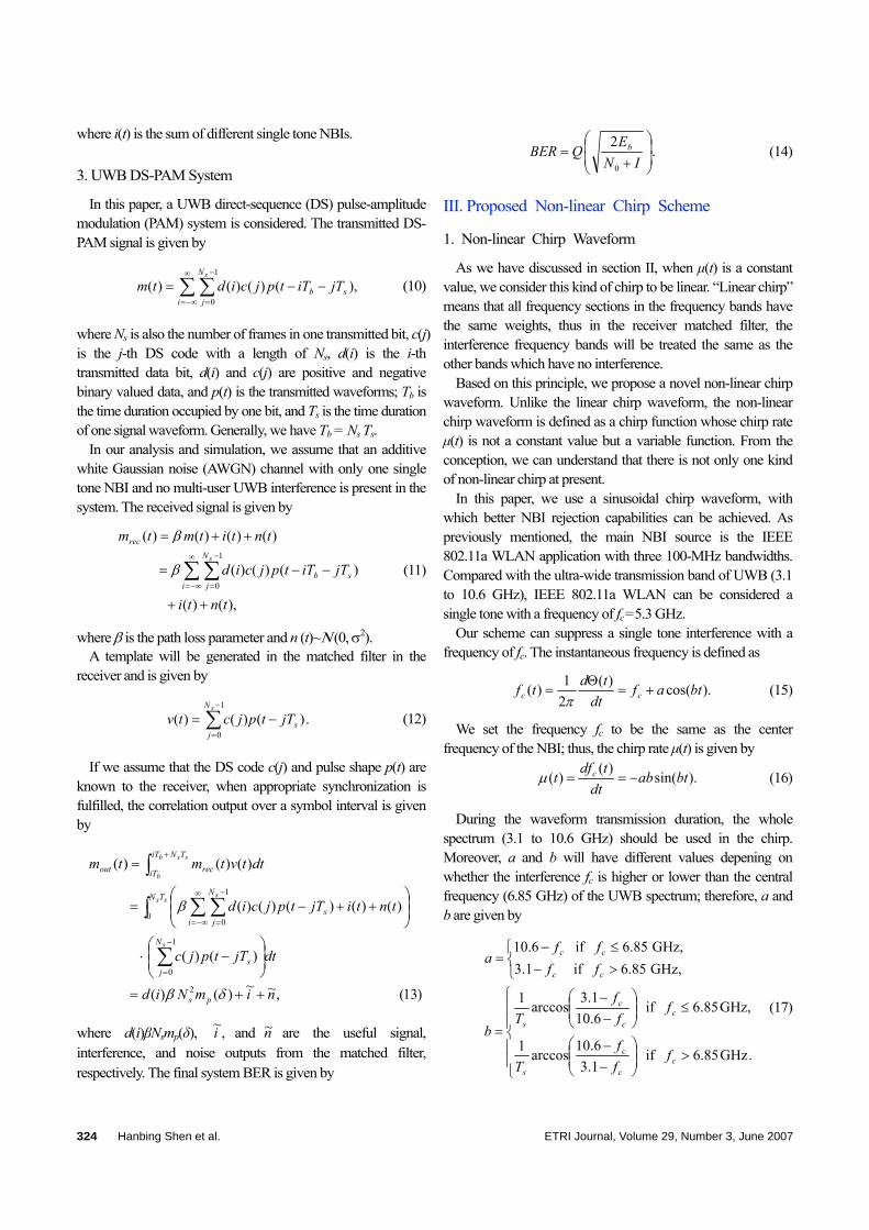
In addition, the BERs of traditional linear chirp methods and the proposed non-linear chirp method are compared in different SIRs. We compared the results of Eb/N0=0 dB and 5 dB. The results are shown in Fig. 6. When the interference power maintains a high level, both systems may reach the BER ceiling of 50%. When the interference power level is low, both systems come close to the ideal BER value. In any cases, a lower BER can be achieved with the proposed non-linear chirp system.
Table 1. Parameters of simulation.
Number of measurements 100,000
Length of one chirp waveform (Ts) 10 ns
Number of chirp waveforms / bit (Ns) 8
Available bandwidth 3.1–10.6 GHz
Central frequency of the NBI (fi) 5.3 GHz
Signal to interference ratio (SIR) -20, -10 dB
Channel model AWGN
Fig. 5. System performance of linear chirp and proposed non-linear chirp in different Eb/N0 values, SIR= -30 dB and -20 dB.
Theoretic BER Linear chirp,SIR = -30 dB Non-linear chirp,SIR = -30 dB Linear chirp,SIR = -20 dB Non-linear chirp,SIR = -20 dB
0 3 6 9 12 110-
54
10-3
10-2
10-1
Eb/N0 (dB)
BE
R
326 Hanbing Shen et al. ETRI Journal, Volume 29, Number 3, June 2007
Fig. 6. System performance of linear chirp and proposed non-linear chirp in different SIRs, Eb/N0= 0 dB and 5 dB.
-40 -35 -30 -25 -20 -15 -10 -5 0
10-2
10-1
100
SIR (dB)
BE
R
Theoretic BER, Eb/N0=0 dBLinear chirp, Eb/N0=0 dB Non-linear chirp, Eb/N0=0 dBTheoretic BER, Eb/N0=5 dBLinear chirp, Eb/N0=5 dB Non-linear chirp, Eb/N0=5 dB
V. Conclusion
In the main allowable spectrum band of UWB, some high power level NBIs exist. They can cause serious problems for UWB transmission and sometimes jam UWB systems. We proposed a novel chirp waveform modulated UWB system to resist these NBIs to some extent. By locating the minimum chirp rate exactly at the frequency of the narrowband interference, the component of the chirp signal at that frequency at the output of the matched filter is less important. Thus, a non-linear chirp with better NBI suppression performance is proposed. Performance analysis and computer simulation results confirm that the proposed scheme outperforms traditional linear schemes in the absence of multi-user UWB interference. Other forms of non-linear chirp such as the arc tangent chirp will be studied in the future works.
References
[1] Revision of Part 15 of the Commission’s Rules Regarding Ultra-wideband Transmission Systems, Federal Communications Commission, ET Docket, 2002, pp. 98-153.
[2] M.Z. Win and R.A. Scholtz, “Impulse Radio: How It Works,” IEEE Commun. Letters, vol. 2, no. 1998, pp. 36-38.
[3] M.Z. Win and R.A. Scholtz. “Ultra-Wide Bandwidth Time-Hopping Spread-Spectrum Impulse Radio for Wireless Multiple-Access Communications,” IEEE Trans. on Commun., vol. 48, no. 4, 2000, pp. 679-689.
[4] M. Ghavami, L.B. Michael, S. Haruyama, and R. Kohno, “A Novel UWB Pulse Shape Modulation System,” Wireless Personal Commun. 2002, pp. 105-120.
[5] M. Ghavami, L.B. Michael, R. Kohno, “Hermite Function Based Orthogonal Pulses for Ultra Wideband Communications,” Proc.
of WPMC ‘01, 2001, pp. 437-440. [6] H. Liu, “Multi-Code Ultra-Wideband Signaling Using Chirp
Waveforms,” Military Communications Conf., 2005, pp. 1-6. [7] X. Chu and R.D. Murch, “The Effect of NBI on UWB Time-
Hopping Systems,” IEEE Trans. on Wireless Commun., 2004, vol. 3, no. 5, pp. 1431-1436.
[8] L.J. Zionmek, Underwater Acoustics: A Linear Systems Theory Approach, Academic Press, 1985.
[9] A. Springer, W. Gugler, M. Huemer, L. Reindl, C.C.W. Ruppel, and R. Weigel, “Spread Spectrum Communications Using Chirp Signals,” EUROCOMM 2000, Information Systems for Enhanced Public Safety and Security, IEEE/AFCEA, 2000, pp. 166-170.
[10] A.J. Berni and W.D. Gregg, “On the Utility of Chirp Modulation for Digital Signaling,” IEEE Trans. on Commun., vol. 21, no. 6, 1973, pp. 748-751.
[11] G.F. Gott and J.P. Newsome, “H.F. Data Transmission Using Chirp Signals,” Proc. of the IEE, vol. 118, no. 9, 1971, pp. 1162-1166.
[12] K. Doi, T. Matsumura, K. Mizutani, and R. Kohno, “Ultra Wideband Ranging System Using Improved Chirp Waveform,” Proc. Radio and Wireless Conf., RAWCON ‘03, 2003, pp. 207-210.
[13] D.P. Morgan. Surface Wave Devices for Signal Processing, Elsevier, Amsterdam, 1985.
Hanbing Shen received the BE in communication engineering (wireless) from Beijing University of Posts and Telecommunications, China, in July 1998, and received the ME in electrical and electronic engineering from the same university in March 2001. During her master degree course, she was a
researcher in Telecommunication Management Network (TMN). After received the ME degree, she worked in the Beijing branch of China Mobile Co., Ltd. in mobile network optimization and maintenance. She joined the Inha Ultra-Wide Band Communication Research Center (INHA UWB-ITRC), Inha University, Incheon, Korea, in Feb. 2004. Her research of interests include UWB sensor network structure, UWB transmitter design, interference suppression technologies in UWB systems, and UWB based cognitive radio (CR) technologies.
ETRI Journal, Volume 29, Number 3, June 2007 Hanbing Shen et al. 327

Weihua Zhang received the BSc and MSc degrees from Beijing University of Posts and Telecommunications, Beijing, China, in July 1998 and April 2003, respectively, in wireless communication engineering. During his graduate studies, he was engaged in WLAN 802.11 protocol and application research. He is
currently working toward the PhD degree in the Inha Ultra-Wide Band Communication Research Center (INHA UWB-ITRC), Inha University, Incheon, Korea. His research interests include pulse shaping, synchronization, interference suppression, and signal processing techniques in UWB systems.
Xizhi An received the BE and ME degrees in information and communication engineering from Xi’an Jiaotong University, China, in 1998 and 2001, respectively. He is currently working towards his PhD degree in the Graduate School of Information Technology and Telecommu-nication at Inha University, Korea. His research
interests include ultra-wideband communications, wireless networks, and cross-layer design.
Kyung Sup Kwak received the BS degree from the Inha University, Inchon, Korea, in 1977; the MS degree from the University of Southern California, in 1981; and the PhD degree from the University of California at San Diego, in 1988, under the Inha University Fellowship and the Korea Electric Association
Abroad Scholarship Grants, respectively. From 1988 to 1989, he was a Member of Technical Staff at Hughes Network Systems, San Diego, California. From 1989 to 1990 he was with the IBM Network Analysis Center at Research Triangle Park, North Carolina. Since then, he has been with the School of Information and Communication, Inha University, Korea, as a professor. He had been the chairman of the School of Electrical and Computer Engineering from 1999 to 2000 and the dean of the Graduate School of Information Technology and Telecommunications from 2001 to 2002 at Inha University, Inchon, Korea. He is the current director of both the Advanced IT Research Center of Inha University, and the UWB Wireless Communications Research Center, a key government IT research center, Korea. Since 1994, he has served as a member of the Board of Directors, and during the term of 2000-2002, he was the vice president for the Korean Institute of Communication Sciences (KICS). He served as KISC’s president in 2006. In 1993, he received the Engineering College Young Investigator Achievement Award from Inha University, and a distinguished service medal from the Institute of Electronics Engineers of Korea (IEEK). In 1996 and 1999, he received Distinguished Service Medals from the KICS. He received the Inha University Engineering Paper Award and the LG Paper Award in 1998 and the Motorola Paper Award in 2000. His research interests include multiple access communication systems, mobile communication systems, UWB radio systems, ad-hoc networks, and sensor networks. Mr. Kwak is a member of IEEE, IEICE, KICS, and KIEE.
328 Hanbing Shen et al. ETRI Journal, Volume 29, Number 3, June 2007