optimal design and control of multi-motor drive system for
TRANSCRIPT
Tehnički vjesnik 27, 6(2020), 1815-1824 1815
ISSN 1330-3651 (Print), ISSN 1848-6339 (Online) https://doi.org/10.17559/TV-20180509152814 Original scientific paper
Optimal Design and Control of Multi-Motor Drive System for Industrial Application
Vojkan KOSTIĆ*, Nebojša MITROVIĆ, Bojan BANKOVIĆ, Filip FILIPOVIĆ, Milutin PETRONIJEVIĆ
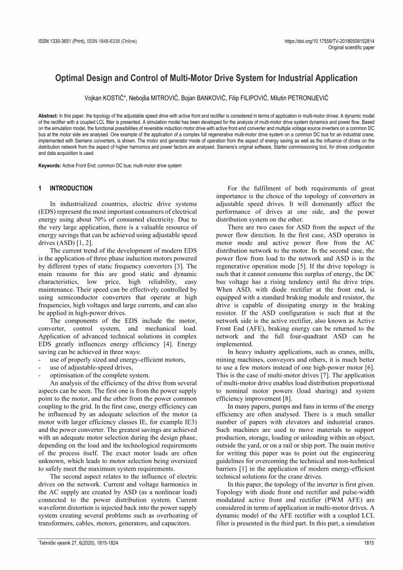
Abstract: In this paper, the topology of the adjustable speed drive with active front end rectifier is considered in terms of application in multi-motor drives. A dynamic model of the rectifier with a coupled LCL filter is presented. A simulation model has been developed for the analysis of multi-motor drive system dynamics and power flow. Based on the simulation model, the functional possibilities of reversible induction motor drive with active front end converter and multiple voltage source inverters on a common DC bus at the motor side are analysed. One example of the application of a complex full regenerative multi-motor drive system on a common DC bus for an industrial crane, implemented with Siemens converters, is shown. The motor and generator mode of operation from the aspect of energy saving as well as the influence of drives on the distribution network from the aspect of higher harmonics and power factors are analysed. Siemens's original software, Starter commissioning tool, for drives configuration and data acquisition is used. Keywords: Active Front End; common DC bus; multi-motor drive system 1 INTRODUCTION
In industrialized countries, electric drive systems (EDS) represent the most important consumers of electrical energy using about 70% of consumed electricity. Due to the very large application, there is a valuable resource of energy savings that can be achieved using adjustable speed drives (ASD) [1, 2].
The current trend of the development of modern EDS is the application of three phase induction motors powered by different types of static frequency converters [3]. The main reasons for this are good static and dynamic characteristics, low price, high reliability, easy maintenance. Their speed can be effectively controlled by using semiconductor converters that operate at high frequencies, high voltages and large currents, and can also be applied in high-power drives.
The components of the EDS include the motor, converter, control system, and mechanical load. Application of advanced technical solutions in complex EDS greatly influences energy efficiency [4]. Energy saving can be achieved in three ways: - use of properly sized and energy‐efficient motors, - use of adjustable‐speed drives, - optimisation of the complete system.
An analysis of the efficiency of the drive from several aspects can be seen. The first one is from the power supply point to the motor, and the other from the power common coupling to the grid. In the first case, energy efficiency can be influenced by an adequate selection of the motor (a motor with larger efficiency classes IE, for example IE3) and the power converter. The greatest savings are achieved with an adequate motor selection during the design phase, depending on the load and the technological requirements of the process itself. The exact motor loads are often unknown, which leads to motor selection being oversized to safely meet the maximum system requirements.
The second aspect relates to the influence of electric drives on the network. Current and voltage harmonics in the AC supply are created by ASD (as a nonlinear load) connected to the power distribution system. Current waveform distortion is injected back into the power supply system creating several problems such as overheating of transformers, cables, motors, generators, and capacitors.
For the fulfilment of both requirements of great importance is the choice of the topology of converters in adjustable speed drives. It will dominantly affect the performance of drives at one side, and the power distribution system on the other.
There are two cases for ASD from the aspect of the power flow direction. In the first case, ASD operates in motor mode and active power flow from the AC distribution network to the motor. In the second case, the power flow from load to the network and ASD is in the regenerative operation mode [5]. If the drive topology is such that it cannot consume this surplus of energy, the DC bus voltage has a rising tendency until the drive trips. When ASD, with diode rectifier at the front end, is equipped with a standard braking module and resistor, the drive is capable of dissipating energy in the braking resistor. If the ASD configuration is such that at the network side is the active rectifier, also known as Active Front End (AFE), braking energy can be returned to the network and the full four-quadrant ASD can be implemented.
In heavy industry applications, such as cranes, mills, mining machines, conveyors and others, it is much better to use a few motors instead of one high-power motor [6]. This is the case of multi-motor drives [7]. The application of multi-motor drive enables load distribution proportional to nominal motor powers (load sharing) and system efficiency improvement [8].
In many papers, pumps and fans in terms of the energy efficiency are often analysed. There is a much smaller number of papers with elevators and industrial cranes. Such machines are used to move materials to support production, storage, loading or unloading within an object, outside the yard, or on a rail or ship port. The main motive for writing this paper was to point out the engineering guidelines for overcoming the technical and non-technical barriers [1] in the application of modern energy-efficient technical solutions for the crane drives.
In this paper, the topology of the inverter is first given. Topology with diode front end rectifier and pulse-width modulated active front end rectifier (PWM AFE) are considered in terms of application in multi-motor drives. A dynamic model of the AFE rectifier with a coupled LCL filter is presented in the third part. In this part, a simulation

Vojkan KOSTIĆ et al.: Optimal Design and Control of Multi-Motor Drive System for Industrial Application
1816 Technical Gazette 27, 6(2020), 1815-1824
model has been developed for the analysis of multi-motor drive system dynamics and power flow. Based on the theoretical analysis from the previous part, in the fourth section, simulation results for the multi-motor drive on a common DC bus during the motor and generator mode are carried out. In the fifth section, one example of the application of a complex full regenerative multi-motor drive on a common DC bus for an industrial crane, implemented with Siemens converters, is shown. The motor and generator mode of operation from the aspect of energy saving as well as the influence of drives on the distribution network from the aspect of higher harmonics and power factors are analysed. At the end, some conclusions are drawn. 2 ELECTRICAL DRIVES TOPOLOGY 2.1 Topology with Diode end Rectifier
Generally, the electrical drive system configuration can be divided into single drive (or stand-alone) and multi-motor drives. In this chapter, the mentioned configurations from the aspect of energy regeneration are shown [5].
A typical power section of a single AC drive consists of three parts. The input section is the line rectifier, which converts a single or three phase AC voltage into a DC voltage, consisting of six diodes. The middle section is the DC link, which contains a capacitor bank for smoothing the DC voltage. The third, and final stage, is the fast switching inverter section, which using a PWM technique, converts the DC voltage into a three phase voltage signal. The power flow in the converter is unidirectional. There are some shortcomings with stand-alone configuration during regeneration, i.e. when the motor is braking or accelerating above the synchronous speed due to the active load. In such cases, the motor operates in a generator mode with the tendency to return energy to the network. Due to the diode bridge at the input, the current cannot flow to the network, the capacitor charging and voltage increase in the DC circuit occurs. In this case, it is very often the case that the inverter is switched off due to overvoltage in the DC circuit. For these reasons, a dynamic brake module with a braking resistor is required to prevent trip level. Fig. 1 shows the experimental results for the variable frequency drive (Danfoss VLT5000) with a braking module in the DC link and an external braking resistor, for induction motor load in the regenerative regime [5]. During the regeneration, there is an increase in voltage at 800 V and current flow, through the chopper, in the resistor as shown in Fig. 1a. After the end of the regenerative period, DC voltage returns to rated value. Fig. 1b shows the line voltage and current at the input of the diode rectifier. The line current harmonic content for the shaded part in Fig. 1b, in Fig. 2 is shown.
In multi-motor drives, a most frequently used solution is the application of common DC bus configuration. Depending on the requirements of the electricity network and the process application, drive systems have different kinds of front end units. From the aspect of the power supply network, the most important selection criterion is an acceptable level of total harmonic distortion (THD). The demands of the technological process mainly relate to the need for frequent braking or regeneration of energy in the network. Accordingly, a common DC bus system can be
divided into two categories: regenerative and non-regenerative.
Figure 1a) DC voltage and chopper current; b) Line voltage and current
Figure 2 Line current harmonic content for 6-pulse diode front end rectifier
A large stand-alone 6 - pulse diode bridge rectifier can
be used to realize a DC bus, which is common to all of the inverters connected in parallel. Power sharing occurs between drives in motor mode and drives in the regenerative operation mode. In this way, it is possible to implement a system that is significantly more efficient than the system in which each inverter has its own rectifier. In order to maintain DC voltage at a safe level, it is necessary that the motoring load is higher than the regenerative one. If regenerating loads are higher than motoring loads, common dynamic braking is applied. The functionality of the braking chopper and the voltage and current waveforms are the same as in Fig. 1. In this case, the diode bridge must have adequate power rating depending on the power of the connected inverters and the load. 2.2 Topology with Active Front end Rectifier
If the ASD configuration is such that at the network side is the active rectifier (AFE), braking energy to the network can be returned [9]. AFE provides four-quadrant operation, which means infeed and regenerative operation mode. There are three main objectives based on AFE technology [10]: - maintain the DC voltage constant regardless of the absolute power value and the power flow direction, - minimize the required current supply (unity power factor), - minimize harmonic content in the supply current, which is achieved by an appropriate control algorithm.
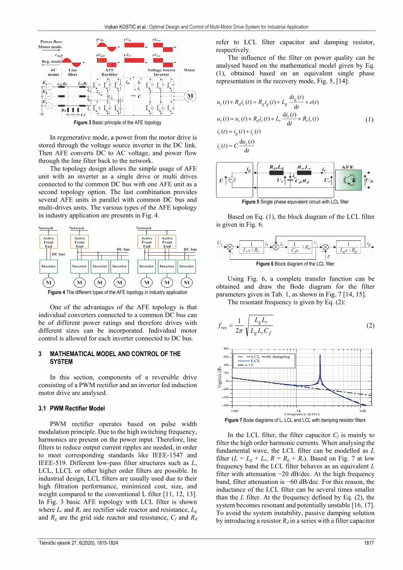
The basic principle of the AFE topology consists of the converter with switchable IGBTs that converts three-phase AC line voltage from the network to the constant and stabilized DC voltage, Fig. 3. To fulfil a control strategy for the drive an inverter on the motor side is needed. The voltage source inverter on the motor side subsequently converts the DC voltage back to AC with variable frequency and voltage. The speed of the connected induction motor in accordance with the applied frequency is then varied.
Vojkan KOSTIĆ et al.: Optimal Design and Control of Multi-Motor Drive System for Industrial Application
Tehnički vjesnik 27, 6(2020), 1815-1824 1817
Figure 3 Basic principle of the AFE topology
In regenerative mode, a power from the motor drive is
stored through the voltage source inverter in the DC link. Then AFE converts DC to AC voltage, and power flow through the line filter back to the network.
The topology design allows the simple usage of AFE unit with an inverter as a single drive or multi drives connected to the common DC bus with one AFE unit as a second topology option. The last combination provides several AFE units in parallel with common DC bus and multi-drives units. The various types of the AFE topology in industry application are presents in Fig. 4.
Figure 4 The different types of the AFE topology in industry application
One of the advantages of the AFE topology is that
individual converters connected to a common DC bus can be of different power ratings and therefore drives with different sizes can be incorporated. Individual motor control is allowed for each inverter connected to DC bus. 3 MATHEMATICAL MODEL AND CONTROL OF THE
SYSTEM
In this section, components of a reversible drive consisting of a PWM rectifier and an inverter fed induction motor drive are analysed. 3.1 PWM Rectifier Model
PWM rectifier operates based on pulse width modulation principle. Due to the high switching frequency, harmonics are present on the power input. Therefore, line filters to reduce output current ripples are needed, in order to meet corresponding standards like IEEE-1547 and IEEE-519. Different low-pass filter structures such as L, LCL, LLCL or other higher order filters are possible. In industrial design, LCL filters are usually used due to their high filtration performance, minimized cost, size, and weight compared to the conventional L filter [11, 12, 13]. In Fig. 3 basic AFE topology with LCL filter is shown where Lr and Rr are rectifier side reactor and resistance, Lg and Rg are the grid side reactor and resistance, Cf and Rd
refer to LCL filter capacitor and damping resistor, respectively.
The influence of the filter on power quality can be analysed based on the mathematical model given by Eq. (1), obtained based on an equivalent single phase representation in the recovery mode, Fig. 5, [14]:
d ( )( ) ( ) ( ) ( )
dd ( )
( ) ( ) ( ) ( )d
( ) ( ) ( )
d ( )( )
d
gc d c g g g
rr c d c r r r
r g c
cc
i tu t R i t R i t L e t
ti t
u t u t R i t L R i tt
i t i t i t
u ti t C
t
(1)
Figure 5 Single phase equivalent circuit with LCL filter
Based on Eq. (1), the block diagram of the LCL filter
is given in Fig. 6.
Figure 6 Block diagram of the LCL filter
Using Fig. 6, a complete transfer function can be
obtained and draw the Bode diagram for the filter parameters given in Tab. 1, as shown in Fig. 7 [14, 15].
The resonant frequency is given by Eq. (2):
frg
rgres CLL
LLf
21
(2)
Figure 7 Bode diagrams of L, LCL and LCL with damping resistor filters
In the LCL filter, the filter capacitor Cf is mainly to
filter the high order harmonic currents. When analysing the fundamental wave, the LCL filter can be modelled as L filter (L = Lg + Lr, R = Rg + Rr). Based on Fig. 7 at low frequency band the LCL filter behaves as an equivalent L filter with attenuation −20 dB/dec. At the high frequency band, filter attenuation is −60 dB/dec. For this reason, the inductance of the LCL filter can be several times smaller than the L filter. At the frequency defined by Eq. (2), the system becomes resonant and potentially unstable [16, 17]. To avoid the system instability, passive damping solution by introducing a resistor Rd in a series with a filter capacitor
Vojkan KOSTIĆ et al.: Optimal Design and Control of Multi-Motor Drive System for Industrial Application
1818 Technical Gazette 27, 6(2020), 1815-1824
is applied. The design of this filter is not treated in this paper, but in the literature, we can find details about the methods for suppression of the resonant frequency [17, 18] as well as methods for selecting the filter parameters [15, 19, 20].
In order to control the active rectifier with LCL filter, a low frequency model is used, where the capacitor Cf is neglected. From Fig. 3, the mathematical model of the three phase PWM rectifier can be defined using the following equation [17, 21]:
d( ) ( ) ( ) ( )
de t Ri t L i t u t
t (3)
where ē(t), ī(t) and ū(t) are grid voltage, converter current and converter side voltage space vectors, respectively.
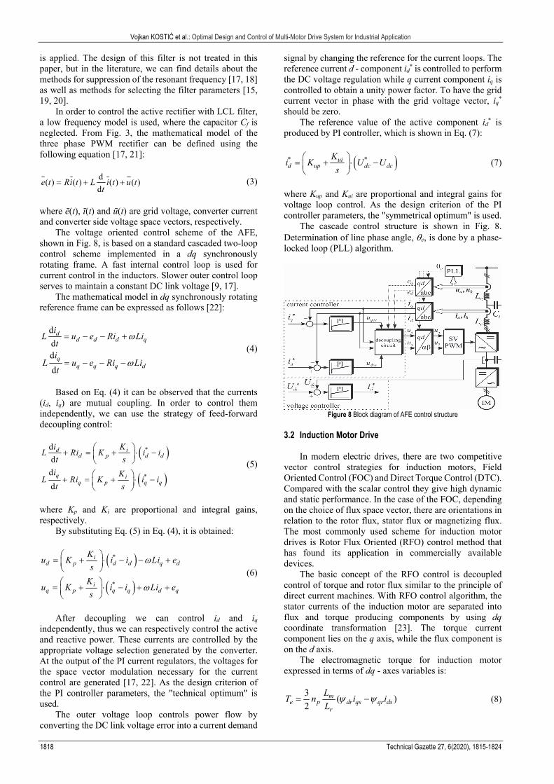
The voltage oriented control scheme of the AFE, shown in Fig. 8, is based on a standard cascaded two-loop control scheme implemented in a dq synchronously rotating frame. A fast internal control loop is used for current control in the inductors. Slower outer control loop serves to maintain a constant DC link voltage [9, 17].
The mathematical model in dq synchronously rotating reference frame can be expressed as follows [22]:
d
dd
d
dd d d q
qq q q d
iL u e Ri Li
ti
L u e Ri Lit
(4)
Based on Eq. (4) it can be observed that the currents
(id, iq) are mutual coupling. In order to control them independently, we can use the strategy of feed-forward decoupling control:
d
d
d
d
*d id p d d
q *iq p q q
i KL Ri K i i
t s
i KL Ri K i i
t s
(5)
where Kp and Ki are proportional and integral gains, respectively.
By substituting Eq. (5) in Eq. (4), it is obtained:
*id p d d q d
*iq p q q d q
Ku K i i Li e
s
Ku K i i Li e
s
(6)
After decoupling we can control id and iq
independently, thus we can respectively control the active and reactive power. These currents are controlled by the appropriate voltage selection generated by the converter. At the output of the PI current regulators, the voltages for the space vector modulation necessary for the current control are generated [17, 22]. As the design criterion of the PI controller parameters, the "technical optimum" is used.
The outer voltage loop controls power flow by converting the DC link voltage error into a current demand
signal by changing the reference for the current loops. The reference current d - component id
* is controlled to perform the DC voltage regulation while q current component iq is controlled to obtain a unity power factor. To have the grid current vector in phase with the grid voltage vector, iq
* should be zero.
The reference value of the active component id* is
produced by PI controller, which is shown in Eq. (7):
* *uid up dc dc
Ki K U U
s
(7)
where Kup and Kui are proportional and integral gains for voltage loop control. As the design criterion of the PI controller parameters, the "symmetrical optimum" is used.
The cascade control structure is shown in Fig. 8. Determination of line phase angle, e, is done by a phase-locked loop (PLL) algorithm.
Figure 8 Block diagram of AFE control structure
3.2 Induction Motor Drive
In modern electric drives, there are two competitive vector control strategies for induction motors, Field Oriented Control (FOC) and Direct Torque Control (DTC). Compared with the scalar control they give high dynamic and static performance. In the case of the FOC, depending on the choice of flux space vector, there are orientations in relation to the rotor flux, stator flux or magnetizing flux. The most commonly used scheme for induction motor drives is Rotor Flux Oriented (RFO) control method that has found its application in commercially available devices.
The basic concept of the RFO control is decoupled control of torque and rotor flux similar to the principle of direct current machines. With RFO control algorithm, the stator currents of the induction motor are separated into flux and torque producing components by using dq coordinate transformation [23]. The torque current component lies on the q axis, while the flux component is on the d axis.
The electromagnetic torque for induction motor expressed in terms of dq - axes variables is:
)(2
3dsqrqsdr
r
mpe ii
L
LnT (8)
Vojkan KOSTIĆ et al.: Optimal Design and Control of Multi-Motor Drive System for Industrial Application
Tehnički vjesnik 27, 6(2020), 1815-1824 1819
where np, Lm and Lr represent the number of pole pairs, the magnetizing inductance and the rotor inductance, ψqr and ψdr are quadratic and direct axis of the rotor flux components, iqs and ids are stator current components.
The d - axis is aligned with the direction of the rotor flux, and consequently, the q-component of rotor flux does not exist (qr = 0). The expression of the torque becomes:
)(2
3 *qsdr
r
mpe i
L
LnT (9)
where estimated flux is:
*
1 dsr
mrdr i
sT
L
(10)
and Tr is rotor time constant.
In order to align the synchronous speed rotating reference frame with the rotor flux, it is necessary to know the module and position of the rotor flux space vector. Therefore, the rotor flux position estimator is composed using references of stator current components and motor parameters. The slip speed is calculated as:
*qs
dr
m
r
rslip i
L
L
r
(11)
where rr is rotor resistance.
Detailed mathematical model of RFO is well-known and can be found in [24-27]. Basic scheme, shown in Fig. 9, introduces multi-rate digital control system with Space Vector PWM (SVPWM) and inner current loop. Outer speed loop superimposed to torque loop is not shown in this figure. The induction motor (IM) with an encoder on the shaft is supplied by voltage source inverter.
Figure 9 Block diagram of RFO control method
4 SIMULATION AND RESULTS ANALYSIS
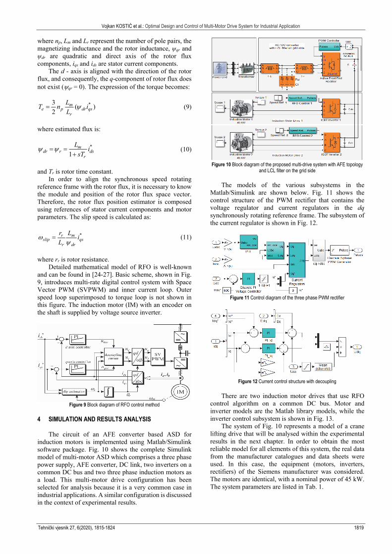
The circuit of an AFE converter based ASD for induction motors is implemented using Matlab/Simulink software package. Fig. 10 shows the complete Simulink model of multi-motor ASD which comprises a three phase power supply, AFE converter, DC link, two inverters on a common DC bus and two three phase induction motors as a load. This multi-motor drive configuration has been selected for analysis because it is a very common case in industrial applications. A similar configuration is discussed in the context of experimental results.
Figure 10 Block diagram of the proposed multi-drive system with AFE topology
and LCL filter on the grid side
The models of the various subsystems in the Matlab/Simulink are shown below. Fig. 11 shows the control structure of the PWM rectifier that contains the voltage regulator and current regulators in the dq synchronously rotating reference frame. The subsystem of the current regulator is shown in Fig. 12.
Figure 11 Control diagram of the three phase PWM rectifier
Figure 12 Current control structure with decoupling
There are two induction motor drives that use RFO
control algorithm on a common DC bus. Motor and inverter models are the Matlab library models, while the inverter control subsystem is shown in Fig. 13.
The system of Fig. 10 represents a model of a crane lifting drive that will be analysed within the experimental results in the next chapter. In order to obtain the most reliable model for all elements of this system, the real data from the manufacturer catalogues and data sheets were used. In this case, the equipment (motors, inverters, rectifiers) of the Siemens manufacturer was considered. The motors are identical, with a nominal power of 45 kW. The system parameters are listed in Tab. 1.

Vojkan KOSTIĆ et al.: Optimal Design and Control of Multi-Motor Drive System for Industrial Application
1820 Technical Gazette 27, 6(2020), 1815-1824
Figure 13 Control subsystem for RFO induction motor drive
Table 1 AFE and inverter parameters
LCL filter parameters E Grid voltage (line-to-line rms) 400 V Lg Grid side filter inductance 0.032 mH Lr Converter side filter inductance 0.319 mH Cf Filter capacitance 39 F Rd Damping resistor 0.3 Ohm
Rectifier parametersP = 160 kW C DC link capacitor 5.22 mF fsw Switching frequency 4 kHz
DC bus voltage PI regulator Kup Proportional gain 3.2 Tui Integral time constant 19.5 ms
Current control loop PI regulator Kp Proportional gain 0.67 Ti Integral time constant 3.75 ms
Inverter parameters P = 55 kW Cdc DC link capacitor 2.82 mF fsw Switching frequency 4 kHz
Speed control loop PI regulator Kp Proportional gain 13.9 Ti Integral time constant 48 ms
Current control loop PI regulator Kcp Proportional gain 0.376 Tci Integral time constant 4 ms
The analysis of such a system is considered from two
aspects. The first is the capability of the drive to develop the appropriate torque in order to maintain the reference speed, and the second is the influence of drives on the network. The presented results are referred to the crane lifting/lowering drive, which consists of two motors. First, the load lifting regime was considered. The crane load was 3/4 of the rated load. The speed reference in the range from 0 to 100% of the synchronous motor speed is set. The motors are equally loaded because both motors are identical and mechanically coupled.
The waveforms of speed, RMS current and electromagnetic torque for a single motor are shown in Fig. 14. The motor starts loaded. It can be seen, from the aspect of the drive, that the motor is able to hold the load at zero reference speed without the load drop. After that, the reference value of the speed in steps of 25, 50, 75 and 100% of the synchronous motor speed is assigned.
Figure 14 Electric drive waveforms during the motor mode
Fig. 15 shows the characteristic waveforms related to the AFE rectifier. The following waveforms were observed: active and reactive power at the input of the rectifier, DC link voltage, grid voltages and grid currents. The switching frequency of the rectifier is set to 4 kHz. With the speed increases, there is an increase in the active power that is taken from the network (about 70 kW at the maximum speed) while the reactive power is zero. On the other hand, regardless of the change in the reference speed of the motor and the active power, DC link voltage remains at a reference value of 600 V. In the same figure, the waveforms of steady state grid current and voltage for two segments are shown. The first segment shows several periods of the phase voltage and current that occur when the drive runs at 25 % of synchronous speed. The second segment refers to the operation of the drive at 100 % of synchronous speed. It can be observed that in all cases the unity power factor is maintained.
Figure 15 AFE variables during the motor mode of drives
Fig. 16 shows the grid current spectrums, in
percentages from fundamental harmonics If, for the higher harmonic orders (h 5), and for all speed range. Also, based on the FFT spectral analysis, the grid current THD is calculated for each of the reference speeds. It can be seen from the current spectrums that there is higher harmonic order near switching frequency, but output current ripples meet the corresponding standards.
Figure 16 Grid current spectrums for different speeds at 3/4 of rated load
The regenerative operating mode of the AFE occurs
when the motors operate in the generator mode during the lowering operation. The simulations were carried out under the same conditions as for the lifting mode.
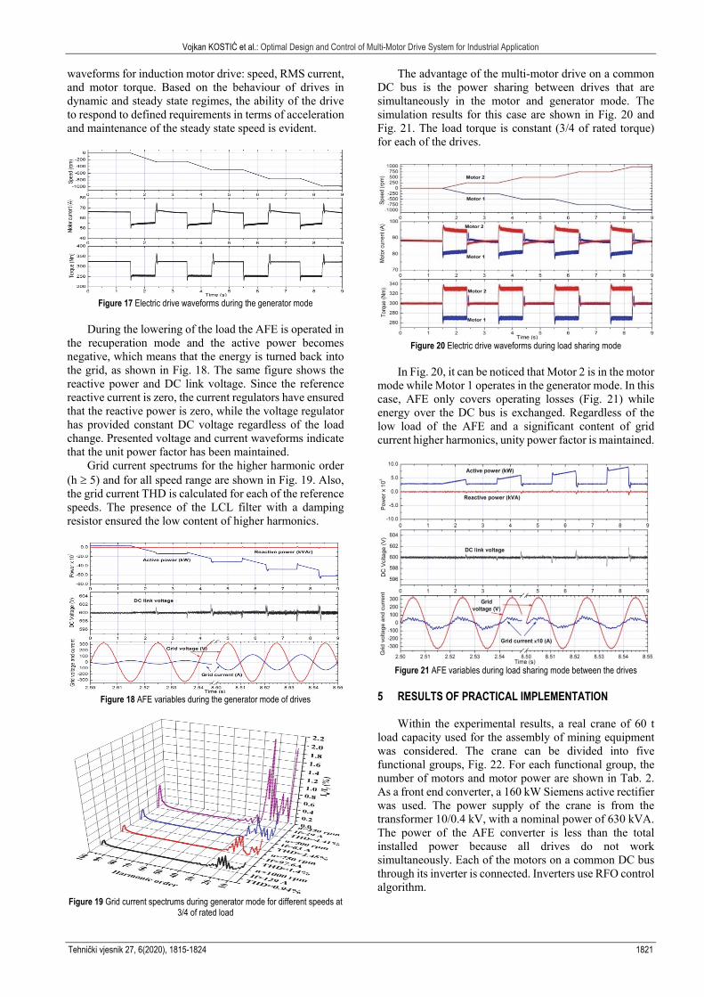
The load is constant and has a value of 3/4 of the rated load. Fig. 17, similar to Fig. 14, shows the relevant
Vojkan KOSTIĆ et al.: Optimal Design and Control of Multi-Motor Drive System for Industrial Application
Tehnički vjesnik 27, 6(2020), 1815-1824 1821
waveforms for induction motor drive: speed, RMS current, and motor torque. Based on the behaviour of drives in dynamic and steady state regimes, the ability of the drive to respond to defined requirements in terms of acceleration and maintenance of the steady state speed is evident.
Figure 17 Electric drive waveforms during the generator mode
During the lowering of the load the AFE is operated in
the recuperation mode and the active power becomes negative, which means that the energy is turned back into the grid, as shown in Fig. 18. The same figure shows the reactive power and DC link voltage. Since the reference reactive current is zero, the current regulators have ensured that the reactive power is zero, while the voltage regulator has provided constant DC voltage regardless of the load change. Presented voltage and current waveforms indicate that the unit power factor has been maintained.
Grid current spectrums for the higher harmonic order (h 5) and for all speed range are shown in Fig. 19. Also, the grid current THD is calculated for each of the reference speeds. The presence of the LCL filter with a damping resistor ensured the low content of higher harmonics.
Figure 18 AFE variables during the generator mode of drives
Figure 19 Grid current spectrums during generator mode for different speeds at
3/4 of rated load
The advantage of the multi-motor drive on a common DC bus is the power sharing between drives that are simultaneously in the motor and generator mode. The simulation results for this case are shown in Fig. 20 and Fig. 21. The load torque is constant (3/4 of rated torque) for each of the drives.
Figure 20 Electric drive waveforms during load sharing mode
In Fig. 20, it can be noticed that Motor 2 is in the motor
mode while Motor 1 operates in the generator mode. In this case, AFE only covers operating losses (Fig. 21) while energy over the DC bus is exchanged. Regardless of the low load of the AFE and a significant content of grid current higher harmonics, unity power factor is maintained.
Figure 21 AFE variables during load sharing mode between the drives
5 RESULTS OF PRACTICAL IMPLEMENTATION
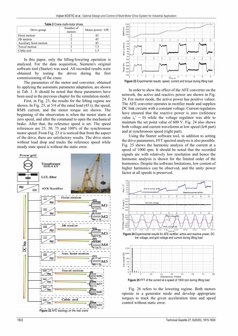
Within the experimental results, a real crane of 60 t load capacity used for the assembly of mining equipment was considered. The crane can be divided into five functional groups, Fig. 22. For each functional group, the number of motors and motor power are shown in Tab. 2. As a front end converter, a 160 kW Siemens active rectifier was used. The power supply of the crane is from the transformer 10/0.4 kV, with a nominal power of 630 kVA. The power of the AFE converter is less than the total installed power because all drives do not work simultaneously. Each of the motors on a common DC bus through its inverter is connected. Inverters use RFO control algorithm.
Vojkan KOSTIĆ et al.: Optimal Design and Control of Multi-Motor Drive System for Industrial Application
1822 Technical Gazette 27, 6(2020), 1815-1824
Table 2 Crane multi-motor drives
Drive group Number of
motors Motor power / kW
Hoist motion 2 45 Jib motion 2 45 Auxiliary hoist motion 1 45 Travel motion 3 7.5 Cable reel 1 1.5
In this paper, only the lifting/lowering operation is
analysed. For the data acquisition, Siemens's original software tool (Starter) was used. All recorded results were obtained by testing the drives during the first commissioning of the crane.
The parameters of the motor and converter, obtained by applying the automatic parameter adaptation, are shown in Tab. 1. It should be noted that these parameters have been used in the previous chapter for the simulation model.
First, in Fig. 23, the results for the lifting regime are shown. In Fig. 23, at 3/4 of the rated load (45 t), the speed, RMS current, and the motor torque are shown. The beginning of the observation is when the motor starts at zero speed, and after the command to open the mechanical brake. After that, the reference speed is set. The speed references are 25, 50, 75 and 100% of the synchronous motor speed. From Fig. 23 it is noticed that from the aspect of the drive, there are satisfactory results. The drive starts without load drop and tracks the reference speed while steady state speed is without the static error.
Figure 22 AFE topology on the real crane
Figure 23 Experimental results: speed, current and torque during lifting load
In order to show the effect of the AFE converter on the
network, the active and reactive power are shown in Fig. 24. For motor mode, the active power has positive values. The AFE converter operates in rectifier mode and supplies DC link circuits with a constant voltage. Current regulators have ensured that the reactive power is zero (reference value iq
* = 0) while the voltage regulator was able to maintain the set point value of 600 V. Fig. 24 also shows both voltage and current waveforms at low speed (left part) and at synchronous speed (right part).
Using the Starter software tool, in addition to setting the drive parameters, FFT spectral analysis is also possible. Fig. 25 shows the harmonic analysis of the current at a speed of 1000 rpm. It should be noted that the recorded signals are with relatively low resolution and hence the harmonic analysis is shown for the limited order of the harmonics. Despite the software limitations, low content of higher harmonics can be observed, and the unity power factor at all speeds is preserved.
Figure 24 Experimental results for AFE rectifier: active and reactive power, DC
link voltage, and grid voltage and current during lifting load
Figure 25 FFT of the current at a speed of 1000 rpm during lifting load
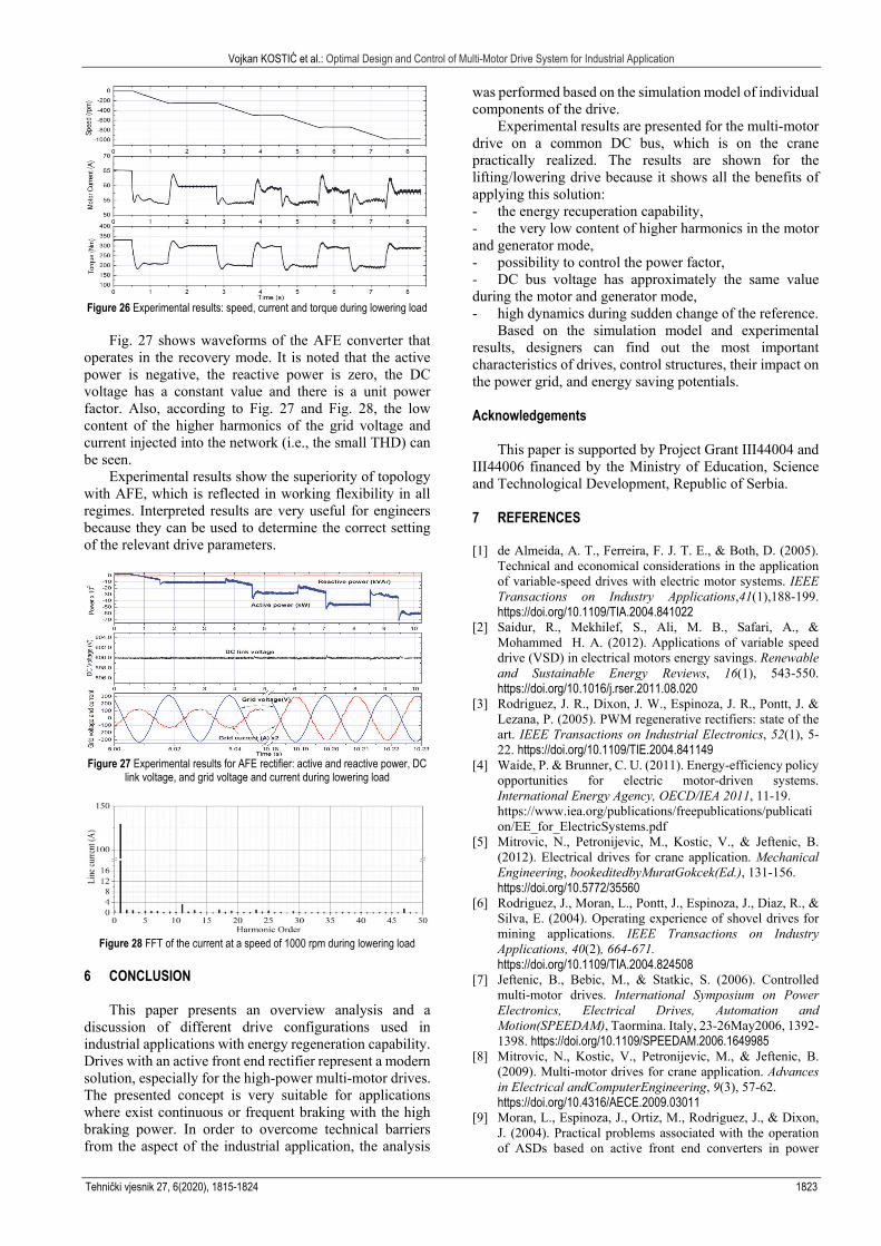
Fig. 26 refers to the lowering regime. Both motors
operate in a generator mode and develop appropriate torques to track the given acceleration time and speed control without static error.
Vojkan KOSTIĆ et al.: Optimal Design and Control of Multi-Motor Drive System for Industrial Application
Tehnički vjesnik 27, 6(2020), 1815-1824 1823
Figure 26 Experimental results: speed, current and torque during lowering load
Fig. 27 shows waveforms of the AFE converter that operates in the recovery mode. It is noted that the active power is negative, the reactive power is zero, the DC voltage has a constant value and there is a unit power factor. Also, according to Fig. 27 and Fig. 28, the low content of the higher harmonics of the grid voltage and current injected into the network (i.e., the small THD) can be seen.
Experimental results show the superiority of topology with AFE, which is reflected in working flexibility in all regimes. Interpreted results are very useful for engineers because they can be used to determine the correct setting of the relevant drive parameters.
Figure 27 Experimental results for AFE rectifier: active and reactive power, DC
link voltage, and grid voltage and current during lowering load
Figure 28 FFT of the current at a speed of 1000 rpm during lowering load
6 CONCLUSION
This paper presents an overview analysis and a discussion of different drive configurations used in industrial applications with energy regeneration capability. Drives with an active front end rectifier represent a modern solution, especially for the high-power multi-motor drives. The presented concept is very suitable for applications where exist continuous or frequent braking with the high braking power. In order to overcome technical barriers from the aspect of the industrial application, the analysis
was performed based on the simulation model of individual components of the drive.
Experimental results are presented for the multi-motor drive on a common DC bus, which is on the crane practically realized. The results are shown for the lifting/lowering drive because it shows all the benefits of applying this solution: - the energy recuperation capability, - the very low content of higher harmonics in the motor and generator mode, - possibility to control the power factor, - DC bus voltage has approximately the same value during the motor and generator mode, - high dynamics during sudden change of the reference.
Based on the simulation model and experimental results, designers can find out the most important characteristics of drives, control structures, their impact on the power grid, and energy saving potentials. Acknowledgements
This paper is supported by Project Grant III44004 and III44006 financed by the Ministry of Education, Science and Technological Development, Republic of Serbia. 7 REFERENCES [1] de Almeida, A. T., Ferreira, F. J. T. E., & Both, D. (2005).
Technical and economical considerations in the application of variable-speed drives with electric motor systems. IEEE Transactions on Industry Applications,41(1),188-199. https://doi.org/10.1109/TIA.2004.841022
[2] Saidur, R., Mekhilef, S., Ali, M. B., Safari, A., & Mohammed H. A. (2012). Applications of variable speed drive (VSD) in electrical motors energy savings. Renewable and Sustainable Energy Reviews, 16(1), 543-550. https://doi.org/10.1016/j.rser.2011.08.020
[3] Rodriguez, J. R., Dixon, J. W., Espinoza, J. R., Pontt, J. & Lezana, P. (2005). PWM regenerative rectifiers: state of the art. IEEE Transactions on Industrial Electronics, 52(1), 5-22. https://doi.org/10.1109/TIE.2004.841149
[4] Waide, P. & Brunner, C. U. (2011). Energy-efficiency policy opportunities for electric motor-driven systems. International Energy Agency, OECD/IEA 2011, 11-19. https://www.iea.org/publications/freepublications/publication/EE_for_ElectricSystems.pdf
[5] Mitrovic, N., Petronijevic, M., Kostic, V., & Jeftenic, B. (2012). Electrical drives for crane application. Mechanical Engineering, bookeditedbyMuratGokcek(Ed.), 131-156. https://doi.org/10.5772/35560
[6] Rodriguez, J., Moran, L., Pontt, J., Espinoza, J., Diaz, R., & Silva, E. (2004). Operating experience of shovel drives for mining applications. IEEE Transactions on Industry Applications, 40(2), 664-671. https://doi.org/10.1109/TIA.2004.824508
[7] Jeftenic, B., Bebic, M., & Statkic, S. (2006). Controlled multi-motor drives. International Symposium on Power Electronics, Electrical Drives, Automation and Motion(SPEEDAM), Taormina. Italy, 23-26May2006, 1392-1398. https://doi.org/10.1109/SPEEDAM.2006.1649985
[8] Mitrovic, N., Kostic, V., Petronijevic, M., & Jeftenic, B. (2009). Multi-motor drives for crane application. Advances in Electrical andComputerEngineering, 9(3), 57-62. https://doi.org/10.4316/AECE.2009.03011
[9] Moran, L., Espinoza, J., Ortiz, M., Rodriguez, J., & Dixon, J. (2004). Practical problems associated with the operation of ASDs based on active front end converters in power
Vojkan KOSTIĆ et al.: Optimal Design and Control of Multi-Motor Drive System for Industrial Application
1824 Technical Gazette 27, 6(2020), 1815-1824
distribution systems. IEEE Industry Applications Conference, 2004. 39th IAS Annual Meeting, 2004, 4(1), 2568-2572. https://doi.org/10.1109/IAS.2004.1348837
[10] Hoppler, R., Maier, U., Ryf, D., & Blahous, L. (2008). Multidrives with active front-end technology in the cement and minerals industry. ABB Review 3/2008, 30-34.
[11] Patel, Y., Pixler, D., & Nasiri, A. (2010). Analysis and design of TRAP and LCL filters for active switching converters. IEEE International Symposium on Industrial Electronics, Bari, 2010, 638-643. https://doi.org/10.1109/ISIE.2010.5637475
[12] Muhlethaler, J., Schweizer, M., Blattmann, R., Kolar, J. W., & Ecklebe, A. (2013). Optimal design of LCL harmonic filters for three-phase PFC rectifiers. IEEE Transactions on Power Electronics, 28(7), 3114-3125. https://doi.org/10.1109/TPEL.2012.2225641
[13] Chaudhari, M. A., Suryawanshi, H. M., & Renge, M. M. (2012). A three-phase unity power factor front-end rectifier for AC motor drive.IETPowerElectronics, 5(1), 1-10. https://doi.org/10.1049/iet-pel.2011.0029
[14] Romdhane, M. B. S., Naouar, M. W., Slama, I., Belkhodja, & Monmasson, E. (2016). Simple and systematic LCL filter design for three-phase grid-connected power converters, Mathematics and Computers in Simulation, 130(1), 181-193. https://doi.org/10.1016/j.matcom.2015.09.011.
[15] Romdhane, M. S., Naouar, M., Belkhodja, I. S., & Monmasson, E. (2017). An improved LCL filter design in order to ensure stability without damping and despite large grid impedance variations. Energies, 10(3), 336. https://doi.org/10.3390/en10030336
[16] Liserre, M., Dell'Aquila, A., & Blaabjerg, F. (2002). Stability improvements of an LCL-filter based three-phase active rectifier. IEEE 33rd Annual IEEE Power Electronics Specialists Conference. Proceedings (Cat. No.02CH37289), 3(1), 1195-1201. https://doi.org/10.1109/PSEC.2002.1022338
[17] Liserre, M., Blaabjerg, F., & Hansen, S. (2005). Design and control of an LCL-filter-based three-phase active rectifier. IEEE Transactions on Industry Applications, 41(5), 1281-1291. https://doi.org/10.1109/TIA.2005.853373
[18] Ye, G., Babar, M., & Cobben, J. F. G. (2014). Performance comparison of different filter applications in three-phase PFC rectifier. 14th International Conference on Environment and Electrical Engineering, Krakow, 2014, pp. 437-442. https://doi.org/10.1109/EEEIC.2014.6835909
[19] Sahoo, A. K., Shahani, A., Basu, K., & Mohan, N. (2014). LCL filter design for grid-connected inverters by analytical estimation of PWM ripple voltage. IEEE Applied Power Electronics Conference and Exposition - APEC 2014, Fort Worth, TX, 1281-1286. https://doi.org/10.1109/APEC.2014.6803471
[20] Huang, M., Wang, X., Loh, P. C., & Blaabjerg, F. (2015). Design of LLCL-filter for grid-connected converter to improve stability and robustness. IEEE Applied Power Electronics Conference and Exposition (APEC), Charlotte, NC, 2959-2966. https://doi.org/10.1109/APEC.2015.7104772
[21] Dannehl, J., Wessels, C., & Fuchs, F. W. (2009). Limitations of voltage-oriented PI current control of grid-connected PWM rectifiers with LCL filters. IEEE Transactions on Industrial Electronics, 56(2), 380-388. https://doi.org/10.1109/TIE.2008.2008774
[22] Hui, L., Chao, X., Chen, C., & Yibing, W. (2014). Simulation of three-phase voltage-source PWM rectifier with LCL filter. Advances in Computer Science and its Applications, Lecture Notes in Electrical Engineering, 279(1), 901-909. Springer, Berlin, Heidelberg. https://doi.org/10.1007/978-3-642-41674-3_127
[23] Krause, P., Wasynczuk, O., Sudhoff, S., & Pekarek, S. (2013). Analysis of electric machinery and drive system, Wiley-IEEE Press, Piscataway, NJ, Jun 2013. https://doi.org/10.1002/9781118524336
[24] Casadei, D., Profumo, F., Serra, G., & Tani, A. (2002). FOC and DTC: two viable schemes for induction motors torque control. IEEE Transactions On Power Electronics, 17(5) 779-787. https://doi.org/10.1109/TPEL.2002.802183
[25] Ozpineci, B. & Tolbert, L. M. (2003). Simulink implementation of induction machine model - a modular approach. IEEE Int. Conf. Electric Machine and Drives, 2(1), 728-734. https://doi.org/10.1109/IEMDC.2003.1210317
[26] Finch, J. W. & Giaouris, D. (2008). Controlled AC electrical drives. IEEE Transactions on Industrial Electronics, 55(2), 481-491. https://doi.org/10.1109/TIE.2007.911209
[27] Mohan, N. (2014). Advanced electric drives: analysis, control, and modelling using MATLAB/Simulink, Published by John Wiley & Sons, Inc., New Jersey. https://doi.org/10.1002/9781118910962
Contact information: Vojkan KOSTIĆ, Assistant (Corresponding author) University of Niš, Faculty of Electronic Engineering, Serbia, 18000 Niš, Aleksandra Medvedeva 14 E-mail: [email protected] Nebojša MITROVIĆ, Full Professor University of Niš, Faculty of Electronic Engineering, Serbia, 18000 Niš, Aleksandra Medvedeva 14 E-mail: [email protected] Bojan BANKOVIĆ, Assistant University of Niš, Faculty of Electronic Engineering, Serbia, 18000 Niš, Aleksandra Medvedeva 14 E-mail: [email protected] Filip FILIPOVIĆ, Assistant University of Niš, Faculty of Electronic Engineering, Serbia, 18000 Niš, Aleksandra Medvedeva 14 E-mail: [email protected] Milutin PETRONIJEVIĆ, Associate Professor University of Niš, Faculty of Electronic Engineering, Serbia, 18000 Niš, Aleksandra Medvedeva 14 E-mail: [email protected]