optical technology for detecting the decomposition
TRANSCRIPT

Optical technology for detecting thedecomposition products of SF6: areview
Xiaoxing ZhangYin ZhangJu TangZhaolun CuiYanglong LiHong ZhouGuangdong ZhangJunting Yang
Xiaoxing Zhang, Yin Zhang, Ju Tang, Zhaolun Cui, Yanglong Li, Hong Zhou, Guangdong Zhang,Junting Yang, “Optical technology for detecting the decomposition products of SF6: a review,” Opt. Eng.57(11), 110901 (2018), doi: 10.1117/1.OE.57.11.110901.
Downloaded From: https://www.spiedigitallibrary.org/journals/Optical-Engineering on 30 Nov 2021Terms of Use: https://www.spiedigitallibrary.org/terms-of-use

Optical technology for detecting the decompositionproducts of SF6: a review
Xiaoxing Zhang,a,* Yin Zhang,a Ju Tang,a Zhaolun Cui,a Yanglong Li,a Hong Zhou,a Guangdong Zhang,b and Junting Yangb
aWuhan University, School of Electrical Engineering, Wuhan, Hubei, ChinabGansu Electric Power Research Institute, Lanzhou, Gansu, China
Abstract. Studies have demonstrated that partial discharge in SF6-insulated electrical equipment can causeSF6 decomposition, resulting in the generation of various products. Quantitative detection of these decompo-sition products can be used to evaluate the state of the equipment’s insulation. The use of optical methods fordetecting the products has many advantages, such as high precision, fast response, and sample reusability.Thus far, optical detection methods have been applied for detection of SF6 decomposition products, and a fewpromising results have been obtained. We review the various optical technologies for detection of SF6 decom-position products, introduce their principles and applications, and summarize some recent research progress. Inaddition, we propose two optical detection technologies that can be applied in this field. © 2018 Society of Photo-OpticalInstrumentation Engineers (SPIE) [DOI: 10.1117/1.OE.57.11.110901]
Keywords: SF6-insulated electrical equipment; SF6 decomposition products; optical detection methods; principle; progress.
Paper 180828V received Jun. 9, 2018; accepted for publication Oct. 30, 2018; published online Nov. 16, 2018.
1 IntroductionSulfur hexafluoride (SF6) is a reliable insulating gas and hasexcellent arc-extinguishing properties. SF6-insulated electri-cal equipment, such as switchgear, transformers, and lines, iswidely used in city power grids and ultrahigh-voltage powertransmission systems owing to its small footprint, high reli-ability, and long service life. Safe and stable operation ofSF6-insulated electrical equipment is crucial for effectivepower supply. However, during the production, installation,and maintenance of SF6-insulated electrical equipment, insu-lation defects such as burrs and metal particles inevitablyappear inside the equipment. Over long-term operation,these defects lead to partial discharge (PD). PD can causedecomposition of SF6 gas, resulting in the production ofvarious low-fluorine sulfides, such as SF4, SF3, SF2, andS2F10.
1–3 Because of the presence of trace impurities, suchas H2O and O2, in the equipment, these low-fluorine sulfidesgenerate many more stable decomposition products, such asSOF2, SO2F2, SO2, and H2S. Simultaneously, PD damagesthe solid insulation of the equipment, causing it to reactwith SF6 to produce CS2, CF4, and other decompositionproducts.4–6 Without accurate detection of these products,defects in the equipment cannot be detected early. PD gradu-ally develops and leads to deterioration of the equipment’sinsulation. Eventually, its effects may even threaten the safeoperation of the entire power grid.
Extant studies show that the components and formationrates of SF6 decomposition products due to different typesof insulation defects are related to the insulation defecttype and its severity.7,8 The detection of SF6 decompositionproducts can help in assessment of the type and severity ofinsulation defects. Therefore, researchers in power industryhope to adopt effective detection of SF6 decomposition
products to ensure timely detection of insulation defectsin the equipment.9–13
The methods of SF6 decomposition products detectioncan be divided into chemical and optical methods. Chemicaldetection employs adsorption, separation, and other methodsand the various physical and chemical properties of differentproducts to detect decomposition product concentrations.The commonly used chemical detection methods are gaschromatography (GC), detection tubes, and gas sensitivitysensors, as listed in Table 1.14–20
GC with high sensitivity is costly, time-consuming, andsuitable for laboratory-based analysis rather than continuouson-line monitoring or portable detection. A detection tubecan be used to detect major decomposition products,such as SO2 or HF, at parts per million (ppm) levels.However, detection tubes have poor accuracy because theconcentration of decomposition products is determined bycolor changes, making these tubes unsuitable for on-linemonitoring.21 A gas-sensitivity sensor can be connected tothe equipment to achieve online monitoring or portabledetection. However, the sensor has poor gas selectivity andis easy to be contaminated.
Optical detection is based on spectral analysis technology,which has been widely used in many fields, such as environ-mental science, medical treatment, chemical engineering,and food science. Most SF6 decomposition products haveabsorption characteristics in both infrared (IR) and ultravio-let (UV) spectra. In different regions, the absorption charac-teristics are different. For example, Fig. 1 shows theabsorption spectrum of the partial decomposition productsof SF6 in the UV region. The strong absorption characteristicin the 190- to 210-nm band corresponds to CS2. If we useUV spectroscopy to detect this product, the detection preci-sion can be improved. However, in the 190- to 210-nm band,interference from H2S and SO2 is present and must be elim-inated. Figure 2 shows the absorption spectrum of the partialdecomposition products of SF6 in the IR region. There isvery little overlap among the spectra of the decomposition
*Address all correspondence to: Xiaoxing Zhang, E-mail: [email protected]
Optical Engineering 110901-1 November 2018 • Vol. 57(11)
Optical Engineering 57(11), 110901 (November 2018) REVIEW
Downloaded From: https://www.spiedigitallibrary.org/journals/Optical-Engineering on 30 Nov 2021Terms of Use: https://www.spiedigitallibrary.org/terms-of-use

products. We can exploit this feature to detect products usinglaser light sources of specific wavelengths to effectivelyeliminate interference from other products.
Compared with chemical detection, optical detection hasmany advantages such as fast response, high sensitivity, onlyrequiring a small sample, and sample reusability. Most of themain SF6 decomposition products can be detected optically.Moreover, optical detection can fulfill all requirements of gasdetection devices in the power industry, including on-linemonitoring and portable detection. Detection devices basedon UV spectroscopy and fluorescence spectroscopy can bemodularized, have a compact structure, and are portable.22,23
Fourier transform infrared spectrometry (FTIR) and photo-acoustic spectroscopy (PAS) have been used for the on-linemonitoring of certain gases.24–27 In summary, optical detec-tion has considerable application potential for the detectionof SF6 decomposition products.
So far, numerous studies regarding the detection of SF6decomposition products have been conducted that haveemployed IR and UV spectroscopy, such as IR spectroscopy,UV fluorescence, and PAS. These studies have obtainedsome relevant results. However, most have focused on a spe-cific method without providing an overview of the variousoptical detection methods. Therefore, herein, we comprehen-sively review the application of optical detection technolo-gies for detecting SF6 decomposition products accordingto UV and IR spectroscopy. In addition, we propose twomethods that can be applied in this field.
2 UV Spectroscopy
2.1 Differential Optical Absorption Spectroscopy
Differential optical absorption spectroscopy (DOAS) wasproposed by NOXON28 in the early 1980s. Platt andPerner29,30—at the Institute of Environmental Physics,Heidelberg University, Germany—extended the technologyto research on the tropospheric atmosphere. The principle ofDOAS involves separating the broadband and narrowbandspectral structures in an absorption spectrum to isolate thenarrow target gas absorption.31 In the absorption spectrum,the influence of Rayleigh scattering, Mie scattering, and tur-bulence causes very broad or smooth spectral characteristics,whereas the target gas exhibits narrowband absorption struc-tures. In Fig. 3, the black line denotes the absorption crosssection, which contains the broadband and narrowband fea-tures, whereas the red line denotes the broadband featureseparated from the absorption cross section. The insetwith the blue line illustrates the differential absorption
Table 1 Commonly used chemical detection methods.
Method Accuracy Speed Anti-interference Range Portability
GC ppb Complex operation,slow detection speed
Strong anti-interferenceability
Most decompositionproducts
Just suitable forlaboratory testing
Detection tube ppm By color comparison,fast detection speed
Easily affected by cross-interference
Partial products, suchas SO2, HF, and otherstrong acid substances
Simple structure, easyto carry
Gas-sensitivity sensor ppm Calculate through thechange of sensorresistance, fastdetection speed
Poor gas selectivity,easy to be
contaminated
SO2, SOF2, SO2F2, andH2S
Good portability
Fig. 1 The absorption spectra of the partial decomposition ofSF6 in UV. All data come from The MPI-Mainz UV/VIS SpectralAtlas, which is a comprehensive collection of cross sections forgaseous molecules and radicals. H2S, WuChen (1998), 295 K, 160to 260 nm; SO2, Danielache (2008), 293 K, 183 to 350 nm; CS2,Ahmed Kumar (1992), 300 K, 188 to 231 nm; SOF2, Pradayrol(1996), 298 K, 123 to 195 nm; SO2F2, Pradayrol (1996), 298 K,130 to 210 nm.
Fig. 2 The absorption spectra of the partial decomposition of SF6 inIR. All data come from HITRAN on the Web, 296 K, 1 atm.
Optical Engineering 110901-2 November 2018 • Vol. 57(11)
Zhang et al.: Optical technology for detecting the decomposition products of SF6: a review
Downloaded From: https://www.spiedigitallibrary.org/journals/Optical-Engineering on 30 Nov 2021Terms of Use: https://www.spiedigitallibrary.org/terms-of-use

cross section, which only contains the absorption feature ofthe target gas.
In DOAS, the influence of spectral absorption caused byRayleigh scattering and Mie scattering can be effectivelyeliminated, and the differential spectrum that only reflectsthe absorption feature of the target gas is obtained. Moreover,when electronic transitions occur in the UV region, they areaccompanied by molecular vibrational and rotational energytransitions. Spectral intensity in UV spectra is several ordersof magnitude higher than that in IR spectra. Therefore, thistechnology has high detection precision.
The decomposition products of SF6 that have absorptioncharacteristics in UV spectroscopy are mainly SO2, H2S, andCS2. These products have been investigated in other fields,such as atmospheric chemistry and environmental engineer-ing. The researchers in these fields have attempted to achievehigh-sensitivity and portable monitoring.32–34 Vita et al.32
could design and construct a lightweight, portable, andlow-power long-path DOAS instrument for use at remotelocations, specifically to measure the degassing from activevolcanic systems, due to the developments in fiber-couplingtelescope technology and the availability of UV light-emit-ting diodes (LEDs). Their instrument could measure SO2 andpotentially other trace gases through long open paths aroundvolcanic vents. The instrument’s SO2 detection limit was8 ppm. Degner et al.33 developed a set of optical sensing sys-tems employing an LED lamp as a light source. Comparedwith the traditional deuterium and xenon light sources, theLED light source is cheaper, longer lasting, more stable,and more suitable for local and on-line monitoring. Thedetection limits of SO2 and NO2 were 1 ppm, and the detec-tion limit of O3 reached 30 parts per billion (ppb). Nasseet al.34 used a laser-driven light source instead of the tradi-tional Xe arc lamp and an optical fiber bundle in the tele-scope for the transmission and reception of the measurementsignal to obtain autonomous long-term trace gas measure-ments. These improvements enhanced the wavelength-selec-tive coupling from the light source into the fiber, whichreduced stray light. Moreover, the coupling and configura-tion of the optical fiber was optimized compared with
previous designs to maximize light throughput and reducestray light.
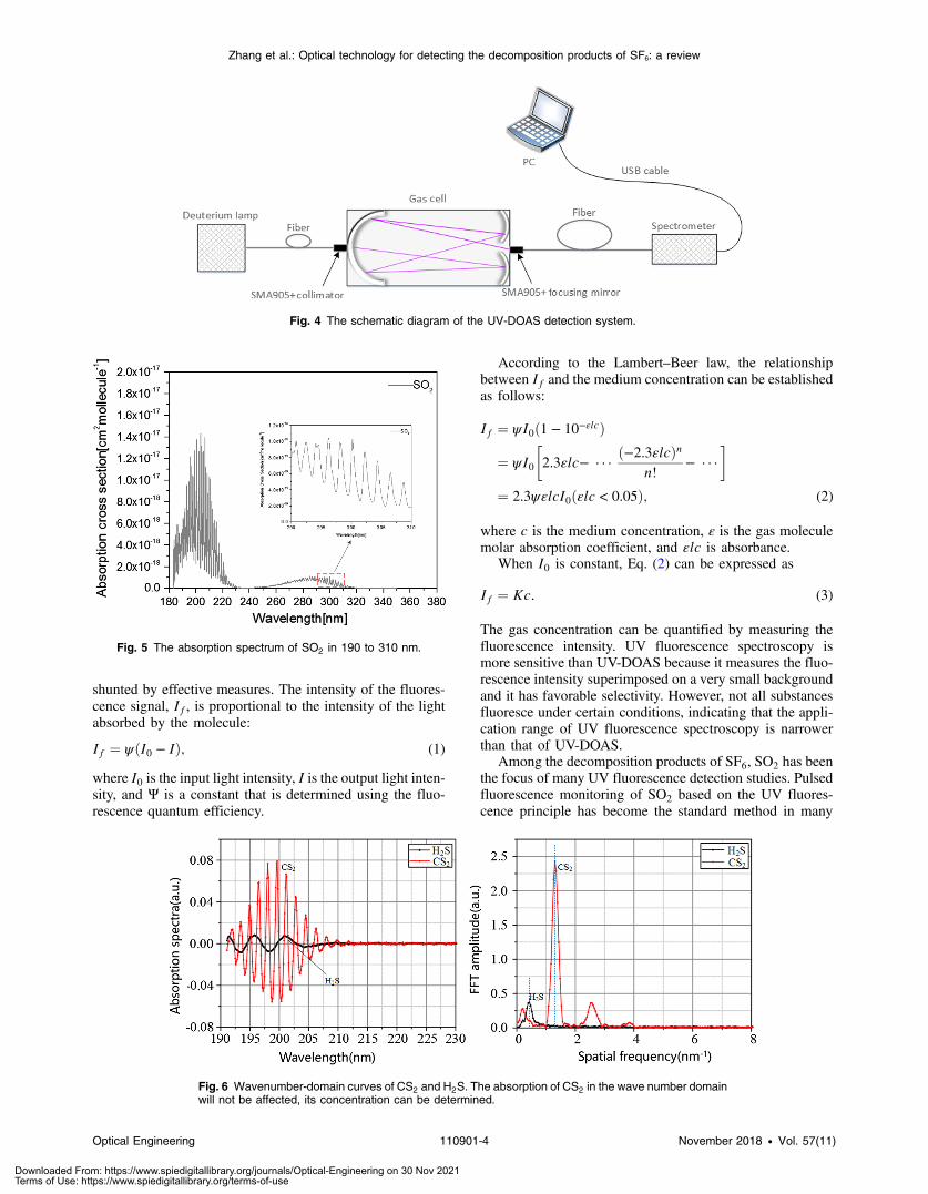
The open paths have been used to increase the opticallength in the applications.32–34 However, these applicationsare unsuitable for detecting the decomposition products ofSF6. The SF6-insulated electrical equipment is enclosed.A suitable option for detecting gas in the equipment involvesintroducing the gas into a gas cell, which is integrated intothe portable device. Zhang et al.35 reported a UV-DOASdevice for detecting SF6 decomposition products with a port-able design, and the schematic diagram is shown in Fig. 4.The device mainly comprised a light source, gas cell, spec-trometer, and laptop. The differential absorption spectrum ofSO2 was obtained by performing Sym14 wavelet-layeringtreatment. The SO2 concentration was calculated accordingto the characteristic peak obtained through fast Fourier trans-formation in the 190- to 230-nm and 290- to 310-nm bands.The results showed that the device had a lower detectionlimit in the 190- to 230-nm band than in the 290- to310-nm band, and the detection limit was 132.4 ppb withsignal-to-noise ratio ðSNRÞ ¼ 3.
Zhang et al.36 also investigated the quantitative detectionof CS2 using this device. The detection limit is 8.65 ppb inthe 190- to 210-nm band. However, Fig. 2 shows that anabsorption spectrum of SO2 continues to exist in thisband. To avoid interference of this product, the absorptionspectrum of the 290- to 310-nm band can be used to detectthe SO2 concentration initially. Then, the interference of SO2
can be deducted to obtain the exact concentration of CS2 inthe 190- to 210-nm band, as shown in Fig. 5.
Few studies have been conducted on the detection of H2Sbased on UV-DOAS. Zhang et al.37 established the relation-ship between the concentration of H2S and its UVabsorptionspectrum using wavelet transform and frequency-domainanalysis. In addition, they studied in detail the overlap ofH2S and CS2 in the 190- to 210-nm band. H2S absorptionin the wave number domain was discovered to be affectedby CS2 and cannot be quantitatively analyzed directly byinversion. However, CS2 absorption in the wave numberdomain remains unaffected, which means that CS2 concen-tration can be determined, as shown in Fig. 6. The influenceof CS2 onH2Swas determined experimentally to confirm thecorrected inversion formula, and thus, quantitative measure-ment of mixed CS2 and H2S gas was realized.
Through multiple studies on portable detection devicesfor SF6 decomposition products, Zhang et al. quantitativelydetected SO2, H2S, and CS2 in the SF6-insulated electricalequipment. The detection device is low cost, with simplestructure, and reliable sensitivity, which makes it suitablefor applications in the power industry.
2.2 UV Fluorescence Method
The UV fluorescence method is a gas quantification methodbased on detection of the intensity of the fluorescence spec-trum emitted by a gas molecule returning to its ground statefrom an excited state. After a molecule absorbs excitationlight of a certain wavelength, it returns to its lowest excitedenergy level through vibration relaxation and subsequentlytransitions downward to generate fluorescence.38 The wave-length of the fluorescence is generally longer than that of theexcitation light. Fluorescence can be measured with a verylow background signal so long as the excitation light is
Fig. 3 Differential spectrum schematic. The black line is the absorp-tion cross section, which contains the broad- and narrowband; the redline is the broadband that is separated from the absorption spectrum;the blue line is the differential absorption cross section.
Optical Engineering 110901-3 November 2018 • Vol. 57(11)
Zhang et al.: Optical technology for detecting the decomposition products of SF6: a review
Downloaded From: https://www.spiedigitallibrary.org/journals/Optical-Engineering on 30 Nov 2021Terms of Use: https://www.spiedigitallibrary.org/terms-of-use
shunted by effective measures. The intensity of the fluores-cence signal, If, is proportional to the intensity of the lightabsorbed by the molecule:
EQ-TARGET;temp:intralink-;e001;63;316If ¼ ψðI0 − IÞ; (1)
where I0 is the input light intensity, I is the output light inten-sity, and Ψ is a constant that is determined using the fluo-rescence quantum efficiency.
According to the Lambert–Beer law, the relationshipbetween If and the medium concentration can be establishedas follows:
EQ-TARGET;temp:intralink-;e002;326;539
If ¼ ψI0ð1 − 10−εlcÞ
¼ ψI0
�2.3εlc− · · ·
ð−2.3εlcÞnn!
− · · ·
�
¼ 2.3ψεlcI0ðεlc < 0.05Þ; (2)
where c is the medium concentration, ε is the gas moleculemolar absorption coefficient, and εlc is absorbance.
When I0 is constant, Eq. (2) can be expressed as
EQ-TARGET;temp:intralink-;e003;326;427If ¼ Kc: (3)
The gas concentration can be quantified by measuring thefluorescence intensity. UV fluorescence spectroscopy ismore sensitive than UV-DOAS because it measures the fluo-rescence intensity superimposed on a very small backgroundand it has favorable selectivity. However, not all substancesfluoresce under certain conditions, indicating that the appli-cation range of UV fluorescence spectroscopy is narrowerthan that of UV-DOAS.
Among the decomposition products of SF6, SO2 has beenthe focus of many UV fluorescence detection studies. Pulsedfluorescence monitoring of SO2 based on the UV fluores-cence principle has become the standard method in many
Fig. 4 The schematic diagram of the UV-DOAS detection system.
Fig. 5 The absorption spectrum of SO2 in 190 to 310 nm.
Fig. 6 Wavenumber-domain curves of CS2 and H2S. The absorption of CS2 in the wave number domainwill not be affected, its concentration can be determined.
Optical Engineering 110901-4 November 2018 • Vol. 57(11)
Zhang et al.: Optical technology for detecting the decomposition products of SF6: a review
Downloaded From: https://www.spiedigitallibrary.org/journals/Optical-Engineering on 30 Nov 2021Terms of Use: https://www.spiedigitallibrary.org/terms-of-use
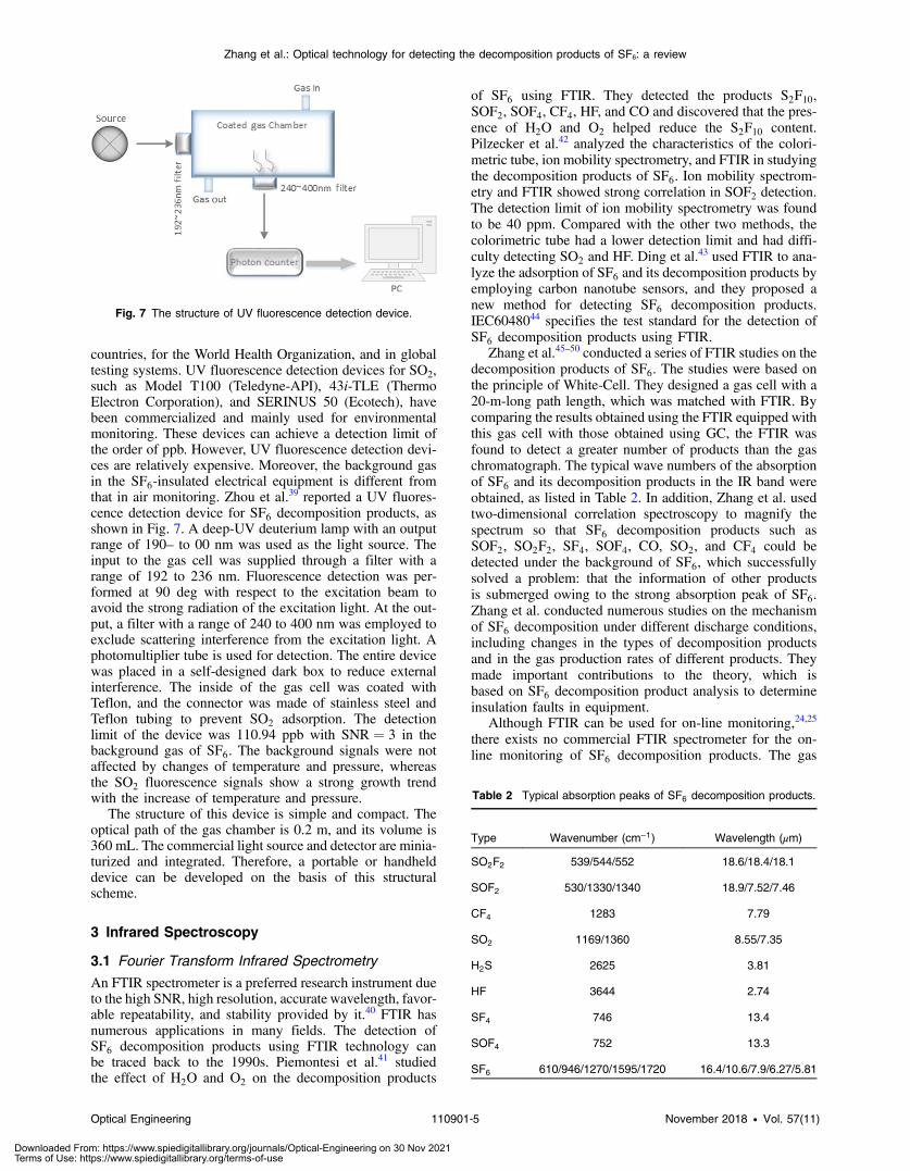
countries, for the World Health Organization, and in globaltesting systems. UV fluorescence detection devices for SO2,such as Model T100 (Teledyne-API), 43i-TLE (ThermoElectron Corporation), and SERINUS 50 (Ecotech), havebeen commercialized and mainly used for environmentalmonitoring. These devices can achieve a detection limit ofthe order of ppb. However, UV fluorescence detection devi-ces are relatively expensive. Moreover, the background gasin the SF6-insulated electrical equipment is different fromthat in air monitoring. Zhou et al.39 reported a UV fluores-cence detection device for SF6 decomposition products, asshown in Fig. 7. A deep-UV deuterium lamp with an outputrange of 190– to 00 nm was used as the light source. Theinput to the gas cell was supplied through a filter with arange of 192 to 236 nm. Fluorescence detection was per-formed at 90 deg with respect to the excitation beam toavoid the strong radiation of the excitation light. At the out-put, a filter with a range of 240 to 400 nm was employed toexclude scattering interference from the excitation light. Aphotomultiplier tube is used for detection. The entire devicewas placed in a self-designed dark box to reduce externalinterference. The inside of the gas cell was coated withTeflon, and the connector was made of stainless steel andTeflon tubing to prevent SO2 adsorption. The detectionlimit of the device was 110.94 ppb with SNR ¼ 3 in thebackground gas of SF6. The background signals were notaffected by changes of temperature and pressure, whereasthe SO2 fluorescence signals show a strong growth trendwith the increase of temperature and pressure.
The structure of this device is simple and compact. Theoptical path of the gas chamber is 0.2 m, and its volume is360 mL. The commercial light source and detector are minia-turized and integrated. Therefore, a portable or handhelddevice can be developed on the basis of this structuralscheme.
3 Infrared Spectroscopy
3.1 Fourier Transform Infrared Spectrometry
An FTIR spectrometer is a preferred research instrument dueto the high SNR, high resolution, accurate wavelength, favor-able repeatability, and stability provided by it.40 FTIR hasnumerous applications in many fields. The detection ofSF6 decomposition products using FTIR technology canbe traced back to the 1990s. Piemontesi et al.41 studiedthe effect of H2O and O2 on the decomposition products
of SF6 using FTIR. They detected the products S2F10,SOF2, SOF4, CF4, HF, and CO and discovered that the pres-ence of H2O and O2 helped reduce the S2F10 content.Pilzecker et al.42 analyzed the characteristics of the colori-metric tube, ion mobility spectrometry, and FTIR in studyingthe decomposition products of SF6. Ion mobility spectrom-etry and FTIR showed strong correlation in SOF2 detection.The detection limit of ion mobility spectrometry was foundto be 40 ppm. Compared with the other two methods, thecolorimetric tube had a lower detection limit and had diffi-culty detecting SO2 and HF. Ding et al.43 used FTIR to ana-lyze the adsorption of SF6 and its decomposition products byemploying carbon nanotube sensors, and they proposed anew method for detecting SF6 decomposition products.IEC6048044 specifies the test standard for the detection ofSF6 decomposition products using FTIR.
Zhang et al.45–50 conducted a series of FTIR studies on thedecomposition products of SF6. The studies were based onthe principle of White-Cell. They designed a gas cell with a20-m-long path length, which was matched with FTIR. Bycomparing the results obtained using the FTIR equipped withthis gas cell with those obtained using GC, the FTIR wasfound to detect a greater number of products than the gaschromatograph. The typical wave numbers of the absorptionof SF6 and its decomposition products in the IR band wereobtained, as listed in Table 2. In addition, Zhang et al. usedtwo-dimensional correlation spectroscopy to magnify thespectrum so that SF6 decomposition products such asSOF2, SO2F2, SF4, SOF4, CO, SO2, and CF4 could bedetected under the background of SF6, which successfullysolved a problem: that the information of other productsis submerged owing to the strong absorption peak of SF6.Zhang et al. conducted numerous studies on the mechanismof SF6 decomposition under different discharge conditions,including changes in the types of decomposition productsand in the gas production rates of different products. Theymade important contributions to the theory, which isbased on SF6 decomposition product analysis to determineinsulation faults in equipment.
Although FTIR can be used for on-line monitoring,24,25
there exists no commercial FTIR spectrometer for the on-line monitoring of SF6 decomposition products. The gas
Fig. 7 The structure of UV fluorescence detection device.
Table 2 Typical absorption peaks of SF6 decomposition products.
Type Wavenumber (cm−1) Wavelength (μm)
SO2F2 539/544/552 18.6/18.4/18.1
SOF2 530/1330/1340 18.9/7.52/7.46
CF4 1283 7.79
SO2 1169/1360 8.55/7.35
H2S 2625 3.81
HF 3644 2.74
SF4 746 13.4
SOF4 752 13.3
SF6 610/946/1270/1595/1720 16.4/10.6/7.9/6.27/5.81
Optical Engineering 110901-5 November 2018 • Vol. 57(11)
Zhang et al.: Optical technology for detecting the decomposition products of SF6: a review
Downloaded From: https://www.spiedigitallibrary.org/journals/Optical-Engineering on 30 Nov 2021Terms of Use: https://www.spiedigitallibrary.org/terms-of-use

cell and quantitative algorithm must be customized if FTIRhas to be used for on-line monitoring. FTIR is primarily usedin the laboratory for analysis. With the long-path gas cell,detecting almost all the SF6 decomposition products is pos-sible. The usual practice involves performing a preliminarydetection of the products in the equipment through the port-able or on-line detection device. If abnormal gases are found,the internal gas of the equipment can be sampled. Detailedanalysis can be then performed in the laboratory using FTIR.
3.2 Photoacoustic Spectroscopy
PAS is an indirect spectroscopic method that combines thetheory of IR absorption spectroscopy with the photoacoustic(PA) effect. The concentration of a gas can be calculated bymeasuring the intensity of the acoustic signal excited by thePA effect. When the excited electrons return to the groundstate, energy is released outward in two ways: radiationand nonradiative transitions, where the nonradiative transi-tion releases heat and changes the ambient pressure. If theincident light is modulated and injected into the gas cellat a certain frequency, a periodic heat source is formedthat changes the pressure periodically, resulting in the gen-eration of an acoustic signal. The gas concentration can becalculated indirectly by detecting the acoustic signal. This isthe basic principle of PAS, as shown in Fig. 8.
PAS has many advantages over traditional absorptionspectroscopy:
1. The strength of PA signals is related to the light energyabsorbed by gas molecules. If there is no absorption,there is no PA signal, so it is a background-lesstechnology.
2. The light intensity detector in traditional absorptionspectroscopes is wavelength-dependent, whereas thedetector used in a PAS is wavelength-independent.
3. PAS offers good stability and high sensitivity. Byusing a laser light source and high-sensitivity micro-phones, theoretical detection limits of the order of ppbcan be achieved;51,52
4. PAS detection system is smaller, has fast response, andis easy to monitor on site.
Based on these advantages, PAS has received widespreadattention. A few studies have reviewed the research on theuse of PAS for gas detection. Elia et al.53 introduced PASgas-sensing technology based on semiconductor lasersources. An IR tunable semiconductor laser was consideredan ideal light source for gas detection, and it has been usedwidely in environmental monitoring, chemical detection,
industrial emission monitoring, and other fields. In addition,the standard PAS and differential PAS methods were sum-marized, and quartz-enhanced PAS was discussed.Pogány54 introduced the development of PAS and discussedthe special problems associated with PAS in practical appli-cations, including the problems of noise and spectral inter-ference. Pogány summarized the practical applications ofPAS, including in environmental monitoring and industrialfields, and outlined prospects for the development of PAS.Miklos55 described three types of PA cells used in PAS—the one-dimensional acoustic resonator [Figs. 9(a) and 9(b)],Helmholtz resonator [Figs. 9(c)], and cavity resonator[Figs. 9(d)–9(f)]—and discussed their application in gasdetection.
PAS can be used to detect SF6 decomposition productswith absorption characteristics in the IR region. Linet al.56 developed a PAS device for detecting SF6 decompo-sition products, as shown in Fig. 10. The device employedbroadband IR light as the light source, a highly sensitiveelectret microphone for sound signal detection, and amechanical chopper for light modulation, and the devicecould detect SO2F2, SO2, CF4, and CO2 with detection pre-cision of 0.831, 1.888, 2.213, and 5.695 μV∕ppm, respec-tively. Qiu et al.57 used a broadband IR source with awavelength of 0.6 to 25 μm to obtain a PAS device fordetecting SOF2. A chopper was employed for modulation.To avoid the influence of the absorption of other products,a filter with a range of 7440� 20 nm was used. The longi-tudinal resonant PA cell was made of pure copper, and bothends were sealed with ZnSe. The measured quality factor ofthe cell was 47. The detection limit of the device was4.6 ppm, and the average error was 5.9%. According toQiu et al., PAS is a reliable method for the on-line monitoringof SF6-insulated electrical equipment.
The performance of PAS can be further enhanced byimproving their components. Wu et al.58 used a customizedquartz tuning fork as a microphone and amplified light powerusing an erbium-doped fiber amplifier. They developed aPAS sensor for detecting H2S, and the detection limit ofthis sensor was 890 ppb. Varga et al.59 developed a two-chan-nel H2S on-line monitoring system with a detection limit of0.5 ppm, which was suitable for the natural gas industry.Laboratory and field tests showed that this system could per-form long-term and stable monitoring in harsh industrialenvironments.
The use of an interferometric cantilever sensor instead ofa conventional microphone can enhance the sensitivity by atleast one order of magnitude.60 Gasera Ltd. had developedvarious PA detectors based on the interferometriccantilever.61,62 The working principle of the cantilever-enhanced PA cell is shown in Fig. 11. Interaction betweenthe gas in the cell and the modulating light leads to changesin pressure. The changing pressure causes the cantilever tovibrate. A Michelson interferometer is employed to opticallymeasure the displacement of the free end of the cantileverand thus acquire a PA signal.
Zhang et al.63 analyzed the decomposition of SF6 and itsreaction with other impurities to form H2S using MaterialsStudio. They then employed a cantilever-enhanced PAS todetect H2S. The PA cell and microsilicon cantilever micro-phone system were manufactured by Gasera Ltd. A distrib-uted feedback laser diode with a center wavelength ofFig. 8 The principle of PAS.
Optical Engineering 110901-6 November 2018 • Vol. 57(11)
Zhang et al.: Optical technology for detecting the decomposition products of SF6: a review
Downloaded From: https://www.spiedigitallibrary.org/journals/Optical-Engineering on 30 Nov 2021Terms of Use: https://www.spiedigitallibrary.org/terms-of-use

1577.86 nm was adopted in the study. The results show thatunder two background gases, N2 and SF6, the detection limitwas 0.84 and 1.75 ppm, respectively. Zhang et al.63 analyzedthe factors that influence cantilever-enhanced PAS gas detec-tion and found that the change in the PA signal amplitudedecreases with an increase in the pressure or temperatureof the PA cell. They also found that the detection platformis more sensitive to pressure than temperature.
The on-line monitoring PAS system has a few commercialapplications. It has promising applications for SF6-insulatedelectrical equipment. After the target gas and correspondinglight source are determined, an on-line monitoring devicewith a PA cell can be developed for SF6 decomposition prod-ucts. A feasible scheme of on-line monitoring PAS for SF6-insulated equipment is shown in Fig. 12. Because the pres-sure in the equipment is several times higher than atmos-pheric pressure, a pressure reducing valve is installed in
Fig. 9 Different types of PA cells. The figure comes from Miklos.55 The (a, b) one-dimensional acousticresonator, (c) the Helmholtz resonator, and (d–f) the cavity resonator.
Fig. 10 The structure of PAS device. The figure reproduced fromRef. 56.
Fig. 11 The principle of the cantilever-enhanced PA cell. Sample cell and micro-Michelsoninterferometer.
Optical Engineering 110901-7 November 2018 • Vol. 57(11)
Zhang et al.: Optical technology for detecting the decomposition products of SF6: a review
Downloaded From: https://www.spiedigitallibrary.org/journals/Optical-Engineering on 30 Nov 2021Terms of Use: https://www.spiedigitallibrary.org/terms-of-use

the gas path. A three-way valve is used to introduce pure anddry N2 to clean the PA cell.
4 Technology for Detecting SF6 DecompositionProducts
With the development of optical detection technology,researchers are pursuing higher detection accuracy, highersensitivity, and faster detection time. Equally, it is hopedthat the structure would be as simple and compact as possiblefor onsite or on-line monitoring. Thus, many optical technol-ogies are continuing to emerge. The following are two tech-nologies that can be used for detecting SF6 decompositionproducts.
4.1 Cavity Ring-Down Spectroscopy
CRDS is a direct absorption technique that can be performedwith pulsed or continuous light sources. A significantlyhigher sensitivity can be obtained with CRDS than with con-ventional absorption spectroscopy. CRDS was formally pro-posed by O’Keefe and Deacon in 1988.64 CRDS uses thering-down time to invert the gas concentration, whichreduces the impact of light source fluctuation on the detec-tion results. In addition, light can be reflected back and forthmultiple times in the ring-down cavity, which can extremelyimprove the gas absorption path.
Pulse CRDS (P-CRDS) is used as an example. Its work-ing principle is shown in Fig. 13. The detection system con-sists of a pulsed laser source, a ring-down cavity composedof two high-reflectance mirrors (>99.9% reflectance), aphotodetector, and other products. The pulsed laser iscoupled with the ring-down cavity, and light is reflectedmultiple times in the ring-down cavity. During each reflec-tion, the laser interacts with the target gas while some weaklight is transmitted. According to the Lambert–Beer law, thetransmitted light signal decays exponentially. The ring-downtime τ is the time required for the light intensity to decay to1∕e of the initial light intensity. The change in the ring-downtime τ reflects the system loss, including intrinsic losses andgas absorption losses. The intrinsic system losses, such asconnector loss and fiber loss, are constant. Therefore, thegas absorption loss can be determined by the change inthe ring-down time τ, and then, the gas concentration canbe calculated. For example, when the ring-down time
decreases, the gas absorption loss increases and the gas con-centration thus increases.
CRDS has strong anti-interference ability and high detec-tion accuracy, and it is suitable for trace gas detection.Several scholars have used it to detect SF6 decompositionproducts. Zhang et al.65 adopted a modular design methodbased on CRDS to design an on-line system for monitoringSF6 decomposition products, and the feasibility of thissystem for detecting SF6 decomposition products wasdemonstrated.
However, the limitation of CRDS lies in its dependenceon ultrahigh-reflectivity mirrors. In actual measurements, ifthe mirror reflectance decreases owing to mirror pollution orring-down cavity vibration, the measurement error is dra-matically increased. Furthermore, pattern matching of thecavity is a problem. To solve these problems, a new typeof CRDS technology is introduced herein: fiber loop ring-down spectroscopy (FLRDS).66–69
FLRDS is based on CRDS. An optical fiber is used toreplace the ring-down cavity, and this fiber directs the pulsedlight to circulate in the fiber loop. The basic principle ofFLRDS is shown in Fig. 14. The equipment is composedof two 2 × 1 couplers and a gas cell. Pulsed light entersthe fiber ring cavity through coupler C1 to circulate, and dur-ing each cycle, the light interacts with the gas in the cell. Asmall percentage of the light enters the photodetectorthrough coupler C2, but most of the light continues to cir-culate in the fiber ring cavity, and this continues until thelight is completely attenuated.
All-fiber connections are employed in FLRDS. Forming afiber sensor network for the on-line monitoring of trace gas iseasy.70 However, the detection precision of FLRDS cannotcurrently meet the requirement of SF6 decompositionproducts.68,71,72 Thus, further detailed research is required.
4.2 Photonic Crystal Fibers
A PCF, also called a microstructured fiber, is shown inFig. 15. The interior of such a fiber can be an air-core struc-ture that allows for the transmission of photons within the aircore.73 This enhances the interaction of light and air, result-ing in higher excitation efficiency and smaller losses. It ispossible to create cells with long absorption paths.
Fig. 12 The schematic diagram of on-line monitoring PAS for the SF6-insulated electrical equipment.(1) Sampling port, (2) metal dust filter, (3) pressure reducing valve, (4) three-way valve, (5) switchvalve, (6) PAS device, (7) pressure sensor, (8) restriction valve, (9) switch valve, (10) vacuum pump,(11) check valve, (12, 13) flow control valve, and (14) passive vibration isolation device.
Optical Engineering 110901-8 November 2018 • Vol. 57(11)
Zhang et al.: Optical technology for detecting the decomposition products of SF6: a review
Downloaded From: https://www.spiedigitallibrary.org/journals/Optical-Engineering on 30 Nov 2021Terms of Use: https://www.spiedigitallibrary.org/terms-of-use

However, it is necessary to consider how to input the gasinto the cell. There are generally two ways to achieve this: tocreate a small gap between the PCF and the input/output ofthe optical fiber to allow gas to flow in; and to use a femto-second laser to drill holes in the side of the PCF, which ena-bles accelerated inflow of gas, as shown in Fig. 16.
Li et al.74 chose to create a gap of 10 μm between the PCFand the input/output of the fibers. They evacuated the gap for
12 h after cleaning it with N2. Then, the target gas flowedinto the PCF cell under a pressure of 100 kpa. The resultsshowed that the transmission loss of CH4 at concentrationsof 0.5% to 4% tended to stabilize after 6 min; the transmis-sion fluctuation for C2H6 with 10% concentration was0.2 dB in the first 2000 s. Jin et al.75 used a femtosecondlaser to drill the side of a 0.62-m-long PCF, and the totalloss after drilling was 4 dB. In addition, they used an all-fiber photothermal spectroscope with the PCF to detectC2H2, obtaining a detection limit of 30 ppb. Lehmannet al.76 indicated the characteristics of different modes ofgas diffusion: a PCF microgap required the use of a vacuumpump or pressurization to inject gas, and the gas diffusiontime was longer. Moreover, fabricating the PCF cell bymeans of femtosecond laser side-drilling was complicated,
Fig. 14 The basic principle of FLRDS.
Fig. 15 The structure of PCF.
Fig. 16 Two ways to make the gas enter into the cell. (a) Using micro-gap and (b) drilling microchannels.
Fig. 13 The principle of CRDS.
Optical Engineering 110901-9 November 2018 • Vol. 57(11)
Zhang et al.: Optical technology for detecting the decomposition products of SF6: a review
Downloaded From: https://www.spiedigitallibrary.org/journals/Optical-Engineering on 30 Nov 2021Terms of Use: https://www.spiedigitallibrary.org/terms-of-use

and there was a risk of destroying the PCF structure duringthe drilling process.
Gas detection with PCFs has extremely high precision.However, the production process of the gas cell is compli-cated. The gas cell may achieve popularity for commercialapplications in the future. Thus, we can continue to payattention to the developments in this field.
5 ConclusionThe various advantages of the optical detection method, suchas high precision and speed, portability, on-line monitoring,and nondestructive measurement, enable it to have goodapplication prospects in the power industry. Different meth-ods have different application scenarios, and their cost,detection technique, and sensitivity also vary. Table 3 sum-marizes the detection methods mentioned herein. BecauseCRDS and PCF have few applications in the detection ofSF6 decomposition products, they are not listed in the table.
The detection devices based on UV-DOAS and UV fluo-rescence can conveniently sample and detect SF6 decompo-sition products on-site. The UV fluorescence device can alsobe modified into a handheld device, which can reduce thework intensity of on-site inspection personnel. The detectiondevices based on UV-DOAS and UV fluorescence have afast response. Moreover, the cost of the UV-DOAS andUV fluorescence devices is lower than that of FTIR andPAS. However, few products can be detected with theUV-DOAS and UV fluorescence devices. FTIR can beused to detect almost all products. Although it can be usedfor on-line monitoring, the operation process for multiprod-uct measurement is complicated. The operators must betrained accordingly. Its response speed is related to the spec-tral resolution. A long time is required to perform a fine-res-olution analysis. Therefore, analyzing the sample gas in thelaboratory through FTIR is the most suitable option. PAS,the most suitable method for on-line monitoring, can beused to detect multiple products with a corresponding lightsource or filter. However, PAS is costlier than the UV-DOASand UV fluorescence devices.
In summary, for the consumer and junction substations,on-line monitoring PAS can be used to ensure real-timeaccess to the insulation. The UV-DOAS and UV fluores-cence devices are cheap and easy to use. These devicescan be used in the routine maintenance of equipment. TheUV-DOAS and UV fluorescence devices can detect limitedcomponents. However, when an abnormal gas is detected, itcan be removed from the equipment for FTIR detection toquantitatively analyze the products in detail. By combining
various optical detection methods, the detection accuracy ofSF6 decomposition products can be ensured. Thus, the typesand severity of insulation defects can be determined in aneffective and a timely manner.
AcknowledgmentsThis work was supported by Key Program of NationalNatural Science Foundation of China (51537009).
References
1. R. J. Van Brunt and J. T. Herron, “Fundamental processes of SF6decomposition and oxidation in glow and corona discharges,” IEEETrans. Electr. Insul. 25(1), 75–94 (1990).
2. F. Y. Chu, “SF6 decomposition in gas-insulated equipment,” IEEETrans. Electr. Insul. EI-21(5), 693–725 (1986).
3. B. Belmadani, J. Casanovas, and A. M. Casanovas, “SF6 decompositionunder power arcs. II. Chemical aspects,” IEEE Trans. Electr. Insul.26(6), 1177–1182 (1991).
4. A. Derdouri et al., “Spark decomposition of SF6∕H2O mixtures,” IEEETrans. Electr. Insul. 24(6), 1147–1157 (1990).
5. C. Beyer, H. Jenett, and D. Klockow, “Influence of reactive SFX gaseson electrode surfaces after electrical discharges under SF6 atmosphere,”IEEE Trans. Dielectr. Electr. Insul. 7(2), 234–240 (2000).
6. J. M. Braun, F. Y. Chu, and R. Seethapathy, “Characterization of GISspacers exposed to SF6 decomposition products,” IEEE Trans. Electr.Insul. EI-22(2), 187–193 (1987).
7. J. Tang et al., “Partial discharge recognition through an analysis of SF6decomposition products part 1: decomposition characteristics of SF6under four different partial discharges,” IEEE Trans. Dielectr. Electr.Insul. 19(1), 29–36 (2012).
8. J. Tang et al., “Partial discharge recognition through an analysis of SF6decomposition products part 2: feature extraction and decision tree-based pattern recognition,” IEEE Trans. Dielectr. Electr. Insul.19(1), 37–44 (2012).
9. S. Tominaga et al., “SF6 gas analysis technique and its application forevaluation of internal conditions in SF6 gas equipment,” IEEE Trans.Power Appar. Syst. PAS-100(9), 4196–4206 (1981).
10. J. M. Braun and F. Y. Chu, “Novel low-cost SF6 arcing byproduct detec-tors for field use in gas-insulated switchgear,” IEEE Trans. PowerDelivery 1(2), 81–86 (1986).
11. J. K. Wittle et al., “Fault-detection sensors for gas insulated equipment,”NASA STI/Recon Technical Report N, 83 (1982).
12. S. Okabe et al., “Detecting characteristics of SF6 decomposed gas sen-sor for insulation diagnosis on gas insulated switchgears,” IEEE Trans.Dielectr. Electr. Insul. 15(1), 251–258 (2008).
13. F. Y. Chu, “Gas analysis as a diagnostic tool for gas-insulatedequipment,” in Gaseous Dielectrics V, L. G. Christophorou andD. Bouldin, Eds., pp. 462–471, Pergamon Press, New York (1987).
14. H. Wang et al., “Detection of ppb level SO2 in H2 by an adsorption–desorption gas chromatography method,” Int. J. Hydrogen Energy35(7), 2994–2996 (2010).
15. H. Chang et al., “Microfabricated gas chromatograph for sub-ppb deter-minations of TCE in vapor intrusion investigations,” Proc. Eng. 5(6),973–976 (2010).
16. Z. Pegram, M. T. Kwasniewski, and G. L. Sacks, “Simplified methodfor free SO2 measurement using gas detection tubes,” Am. J. Enol. Vitic.64(3), 405–410 (2013).
17. X. Zhang et al., “Mechanism and application of carbon nanotube sen-sors in SF6 decomposed production detection: a review,” NanoscaleRes. Lett. 12(1), 177 (2017).
Table 3 Several optical detection methods for SF6 decomposition products.
Method
Types
Application Cost Sensitivity SpeedSO2 H2S CS2 SOF2 SO2F2 CF4
UV-DOASp p p
Portable Medium Sub-ppm Fast
UV fluorescencep
Portable or handheld Low Sub-ppm Fast
FTIR (with 20 m gas cell)p p p p p
Laboratory or on-line monitoring High ppm Medium
PASp p p p p
On-line monitoring High Sub-ppm Fast
Optical Engineering 110901-10 November 2018 • Vol. 57(11)
Zhang et al.: Optical technology for detecting the decomposition products of SF6: a review
Downloaded From: https://www.spiedigitallibrary.org/journals/Optical-Engineering on 30 Nov 2021Terms of Use: https://www.spiedigitallibrary.org/terms-of-use
18. X. Zhang, Y. Gui, and X. Dong, “Preparation and application of TiO2nanotube array gas sensor for SF6-insulated equipment detection: areview,” Nanoscale Res. Lett. 11(1), 302 (2016).
19. X. Zhang, “Experimental study of carbon nanotubes gas sensordetecting SF6 partial discharge decomposition components,” Trans.China Electrotechn. Soc. 26(11), 121–126 (2011).
20. X.-X. Zhang et al., “DFT calculations on the adsorption of componentSF6 decomposed under partial discharge onto carbon nanotubesmodified by -OHoh,” Acta Phys. Sin. 61(15), 415–418 (2012).
21. J. Suehiro, G. Zhou, and M. Hara, “Detection of partial discharge in SF6gas using a carbon nanotube-based gas sensor,” Sens. Actuators B105(2), 164–169 (2005).
22. S. Camou et al., “PPB-level detection of benzene diluted in water bybubbling extraction system and UV spectroscopy based measurements,”in TRANSDUCERS Int. Solid-State Sensors, Actuators andMicrosystems Conf., IEEE, pp. 261–264 (2007).
23. K. Davitt et al., “290 and 340 nm UV LED arrays for fluorescencedetection from single airborne particles,” Opt. Express 13(23), 9548–55 (2005).
24. K. Kortenbruck et al., “Determination of the diffusion coefficient ofCO2, in the ionic liquid EMIM NTf 2 using online FTIR measure-ments,” J. Chem. Thermodyn. 47(12), 76–80 (2012).
25. A. Sánchez, E. Eddings, and F. Mondragón, “Fourier transform infrared(FTIR) online monitoring of NO, N2O, and CO2 during oxygen-enriched combustion of carbonaceous materials,” Energy Fuels24(9), 4849–4853 (2010).
26. F. J. M. Harren et al., “Photoacoustic spectroscopy in trace gas mon-itoring,” in Encyclopedia of Analytical Chemistry, R. A. Meyers,Ed., pp. 2203–2226, John Wiley & Sons, Ltd., Chichester, England(2000).
27. M. W. Sigrist, “Trace gas monitoring by laser photoacoustic spectros-copy and related techniques (plenary),” Rev. Sci. Instrum. 74(1),486–490 (2003).
28. J. F. Noxon, “Nitrogen dioxide in the stratosphere and troposphere mea-sured by ground-based absorption spectroscopy,” Science 189(4202),547–549 (1975).
29. U. Platt, D. Perner, and H. W. Pätz, “Simultaneous measurement ofatmospheric CH2O, O3, and NO2 by differential optical absorption,”J. Geophys. Res. 84(C10), 6329–6335 (1979).
30. U. Platt and D. Perner, “Direct measurements of atmospheric CH2O,HNO2, O3, NO2, SO2 by differential optical absorption in the nearUV,” J. Geophys. Res. 85(C12), 7453–7458 (1980).
31. U. Platt and J. Stutz, Differential Optical Absorption Spectroscopy(DOAS)—Principles and Applications, p. 15, Springer, Berlin(2008).
32. F. Vita, C. Kern, and S. Inguaggiato, “Development of a portableactive long-path differential optical absorption spectroscopy system forvolcanic gas measurements,” J. Sens. Sens. Syst. 3(2), 355–367 (2014).
33. M. Degner et al., “High resolution led-spectroscopy for sensor applica-tion in harsh environment,” in Instrumentation and MeasurementTechnology Conf., IEEE, pp. 1382–1386 (2010).
34. J. M. Nasse et al., “Autonomous long-term trace gas measurementsusing long-path differential optical absorption spectroscopy,” in EGUGeneral Assembly Conf., EGU General Assembly Conference Abstracts(2017).
35. H. Zhou et al., “Quantum detection of trace sulfur dioxide based onultraviolet differential optical absorption spectrometry,” Proc. CSEE37(19), 5812–5820 (2017).
36. X. Zhang et al., “Ultraviolet differential optical absorption spectrom-etry: quantitative analysis of the CS2 produced by SF6 decomposition,”Meas. Sci. Technol. 28(11), 115102 (2017).
37. X. Zhang et al., “Quantitative detection of H2S and CS2 mixed gasesbased on UV absorption spectrometry,” RSC Adv. 7(80), 50889–50898(2017).
38. H. Okabe, P. Splitstone, and J. Ball, “Ambient and source SO2 detectorbased on a fluorescence method,” J. Air Pollut. Control Assoc. 23(6),514–516 (1973).
39. X. Zhang et al., “Quantitative detection of SO2 produced by SF6 decom-position based on ultraviolet fluorescence method,” Electric PowerAutom. Equip. 38(6), 177–182 (2018).
40. P. R. Griffths, “Fourier transform infrared spectrometry,” Science222(4621), 297–302 (1983).
41. M. Piemontesi, R. Pietsch, and W. Zaengl, “Analysis of decompositionproducts of sulfur hexafluoride in negative dc corona with specialemphasis on content of H2O and O2,” in Conf. of the IEEE Int.Symp. on Electrical Insulation, IEEE, pp. 499–503 (1994).
42. P. Pilzecker, J. I. Baumbach, and R. Kurte, “Detection of decompositionproducts in SF6: a comparison of colorimetric detector tubes andion mobility spectrometry,” in Annual Report Conf. on ElectricalInsulation and Dielectric Phenomena, IEEE, pp. 865–868 (2002).
43. W. Ding et al., “Analysis of PD-generated SF6 decomposition gasesadsorbed on carbon nanotubes,” IEEE Trans. Dielectr. Electr. Insul.13(6), 1200–1207 (2006).
44. IEC, “Guidelines for the checking and treatment of sulfur hexafluoride(SF6) taken from electrica1 equipment and specification for its re-use,”60480-2004, IEC, Geneva (2004).
45. X. X. Zhang et al., “Infrared spectrum characteristic and discharge trendof SF6 decomposition products,” High Voltage Eng. 35(12), 2970–2976(2009).
46. X. X. Zhang et al., “Recognition of SF6 decomposition components bytwo-dimensional infrared spectroscopy,” High Voltage Eng. 36(6),1475–1479 (2010).
47. X. X. Zhang et al., “SF6 decomposition components IR measurementand quantify,” Gaodianya Jishu/High Voltage Eng. 36(3), 584–589(2010).
48. X. Zhang et al., “Separating overlapped chromatogram signals ofSF6 decomposed products under PD of conductive particles basedon curve-fitting,” Trans. China Electrotechn. Soc. 25(7), 179–185(2010).
49. X. Zhang et al., “Research on long optical paths for SF6 partialdischarge decomposition components’ infrared detection,” Trans.China Electrotech. Soc. 27(5), 70–76 (2012).
50. X. Zhang et al., “Fourier transform infrared spectroscopy quantitativeanalysis of SF6 partial discharge decomposition components,”Spectrochim. Acta Part A 136(B), 884–889 (2015).
51. D. C. Dumitras et al., “Laser photoacoustic spectroscopy: a powerfultool for measurement of trace gases of biological interest at sub-ppblevel,” Mol. Cryst. Liq. Cryst. 418(1), 217–227 (2004).
52. H. Huszár et al., “Ammonia monitoring at ppb level using photoacousticspectroscopy for environmental application,” Sens. Actuators B 134(2),1027–1033 (2008).
53. A. Elia et al., “Photoacoustic techniques for trace gas sensing based onsemiconductor laser sources,” Sensors 9(12), 9616–9628 (2009).
54. A. Pogány, “Photoacoustic instruments for practical applications:present, potentials, and future challenges,” Appl. Spectrosc. Rev. 46(1),1–37 (2015).
55. A. Miklos, P. Hess, and Z. Bozoki, “Application of acoustic resonatorsin photoacoustic trace gas analysis and metrology,” Rev. Sci. Instrum.72(4), 1937–1955 (2001).
56. T. Lin et al., “Photoacoustic detection of SF6 decomposition by-prod-ucts with broadband infrared source,” in Int. Conf. on Power SystemTechnology, IEEE, pp. 1541–1546 (2014).
57. Y. Qiu et al., “Photoacoustic spectroscopy detection of SOF2 character-istic component engendered in SF6 decomposition under partial dis-charge,” High Voltage Eng. 39(5), 1163–1169 (2013).
58. H.Wu et al., “Quartz enhanced photoacousticH2S gas sensor based on afiber-amplifier source and a custom tuning fork with large prongspacing,” Appl. Phys. Lett. 107(11), 111104 (2015).
59. A. Varga et al., “Photoacoustic system for on-line process monitoring ofhydrogen sulfide (H2S) concentration in natural gas streams,” Appl.Phys. B 85(2–3), 315–321 (2006).
60. V. Koskinen et al., “Progress in cantilever enhanced photoacousticspectroscopy,” Vib. Spectrosc. 48(1), 16–21 (2008).
61. V. Koskinen et al., “Cantilever enhanced photoacoustic detection ofcarbon dioxide using a tunable diode laser source,” Appl. Phys. B86(3), 451–454 (2007).
62. J. Uotila, “A new design of the differential photoacoustic gas detectorcombined with a cantilever microphone,” Eur. Phys. J. Spec. Top.153(1), 401–404 (2008).
63. X. Zhang, Z. Cheng, and X. Li, “Cantilever enhanced photoacousticspectrometry: quantitative analysis of the trace H2S produced bySF6, decomposition,” Infrared Phys. Technol. 78, 31–39 (2016).
64. A. O’Keefe and D. A. G. Deacon, “Cavity ring-down optical spectrom-eter for absorption measurements using pulsed laser sources,” Rev. Sci.Instrum. 59(12), 2544–2551 (1988).
65. C. Zhang et al., “CRDS based SF6 decomposition detection technologyfor SF6 electrical equipment,” South. Power Syst. Technol. 10(05),68–74 (2016).
66. R. S. Brown et al., “Fiber-loop ring-down spectroscopy,” J. Chem. Phys.117(23), 10444–10447 (2002).
67. C. Wang, “Fiber loop ringdown—a time-domain sensing technique formulti-function fiber optic sensor platforms: current status and designperspectives,” Sensors 9(10), 7595–7621 (2009).
68. C. Wang and S. T. Scherrer, “Fiber loop ringdown for physicalsensor development: pressure sensor,” Appl. Opt. 43(35), 6458–64(2004).
69. A. Yolalmaz et al., “Intracavity gas detection with fiber loop ring downspectroscopy,” Opt. Commun. 396, 141–145 (2017).
70. C. Zhu et al., “A method for real-time monitoring of inherent systemloss designed for FLRDS-based gas sensors,” IEEE Photonics J.8(5), 1–8 (2016).
71. Y. Zhao, L. Bai, and Q. Wang, “Gas concentration sensor based on fiberloop ring-down spectroscopy,” Opt. Commun. 309(22), 328–332(2013).
72. Y. Zhao et al., “Novel gas sensor combined active fiber loop ring-downand dual wavelengths differential absorption method,” Opt. Express22(9), 11244–11253 (2014).
73. W. Urbanczyk et al., “Photonic crystal fibers for sensing applications,”J. Sens. 2012, 1–21 (2012).
74. X. Li et al., “NIR spectrum analysis of natural gas based on hollow-core photonic bandgap fiber,” IEEE Sens. J. 12(7), 2362–2367(2012).
Optical Engineering 110901-11 November 2018 • Vol. 57(11)
Zhang et al.: Optical technology for detecting the decomposition products of SF6: a review
Downloaded From: https://www.spiedigitallibrary.org/journals/Optical-Engineering on 30 Nov 2021Terms of Use: https://www.spiedigitallibrary.org/terms-of-use

75. J. Wei et al., “Ultra-sensitive all-fibre photothermal spectroscopy withlarge dynamic range,” Nat. Commun. 6, 6767 (2015).
76. H. Lehmann et al., “In-line gas sensor based on a photonic bandgapfiber with laser-drilled lateral microchannels,” IEEE Sens. J. 11(11),2926–2931 (2011).
Xiaoxing Zhang received his bachelor’s and master’s degrees fromHubei Institute of Technology, and doctor’s degree from ChongqingUniversity. He is a professor at the School of Electric Engineering,Wuhan University. He is involved in the on-line monitoring and
fault diagnosis of high voltage electrical insulation equipment, alterna-tive gases of SF6, the decomposition mechanism of insulating gas SF6,and the new optical sensor.
Yin Zhang is a doctoral candidate in School of Electric Engineering,Wuhan University. His research interests include the decompositionmechanism of insulating gas SF6, and the new optical sensor.
Biographies for the other authors are not available.
Optical Engineering 110901-12 November 2018 • Vol. 57(11)
Zhang et al.: Optical technology for detecting the decomposition products of SF6: a review
Downloaded From: https://www.spiedigitallibrary.org/journals/Optical-Engineering on 30 Nov 2021Terms of Use: https://www.spiedigitallibrary.org/terms-of-use