dario scotto - detecting and imaging magneto-optically trapped rubidium-85 ions through near-field...
TRANSCRIPT
Detecting and Imaging Magneto-Optically Trapped Rubidium-85 Ions Through Near-Field
Scanning Optical Microscopy
Dario O. Scotto
Department of Physics, Montana State University, Bozeman, MT
(12 December 2016)
Abstract
An electro-optical design for the experimental trapping and imaging of trapped rubidium-85 ions is given.
Techniques from Near-field Scanning Optical Microscopy are implemented in the probe and detection
aspects of the design. Etched fibers are chosen for their geometric properties so that a sample of trapped
ions on the order less than a single nanometer may be detected with little disturbance. These detection
techniques are paired with two trapping methods so that the rubidium-85 ions may be isolated and
imaged. Three orthogonally crossed beams tuned to just below the rubidium-85 D2 transition line will be
employed to produce an optical molasses that will cool the rubidium-85. This trap will be assisted by a
magneto-trap consisting of an anti-Helmholtz coil pair to take advantage Zeeman shifting for further
cooling and confinement. A crash course introduction into the theoretical concepts central to this
experiment is given such that the purpose of all elements of the design may be understood.
-------------------------------------------------------------------------------------------------------------
Presented here is the outline of the employment of NSOM techniques to detect and manipulate trapped
rubidium ions. The design thus far is tentative and is part of the undergraduate research I am undertaking
with Dr. Alan Craig, a resident research professor at Montana State University. If our efforts with
rubidium are successful then the prospects of trapping electrons will be explored. Information researched
from a number of distinct fields will contribute to the overall process of design. These include techniques
and tools used in near-field scanning optical microscopy, electromagnetism, quantum optics, and control
theory.
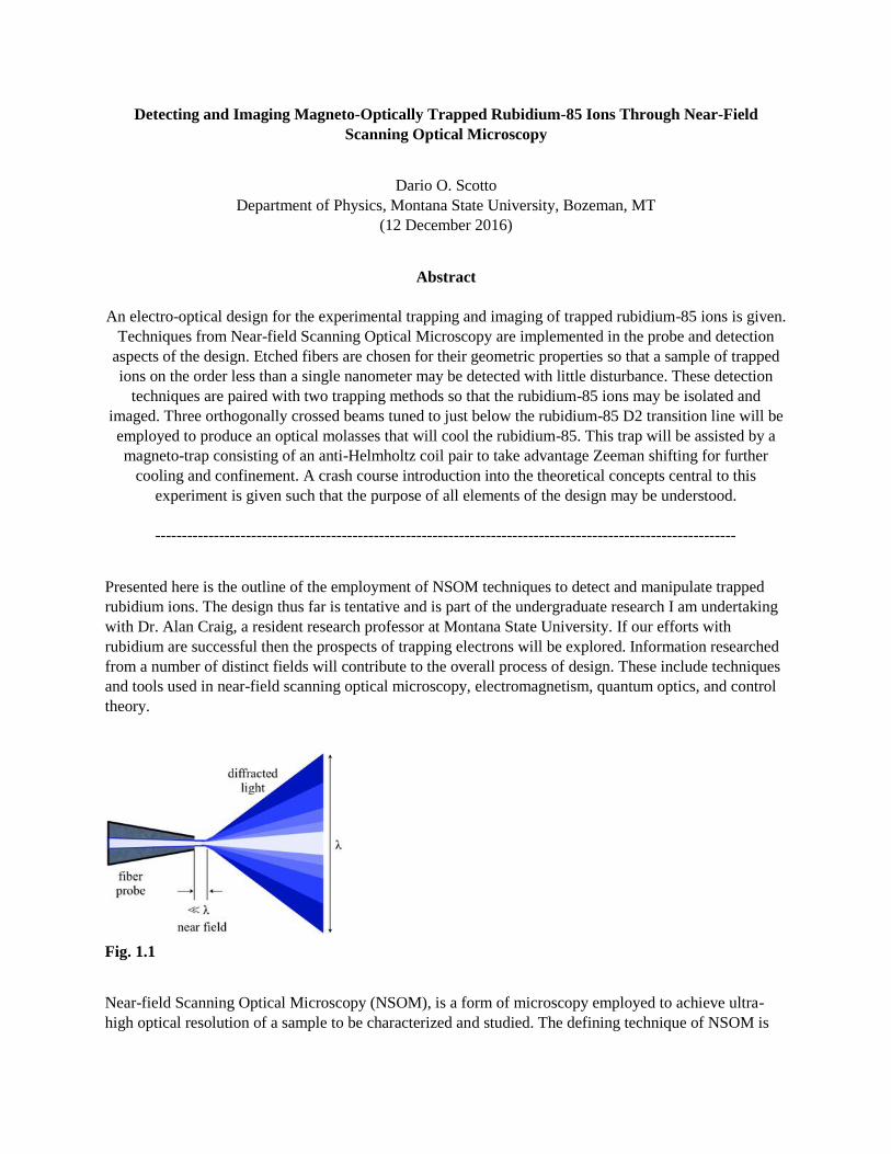
Fig. 1.1
Near-field Scanning Optical Microscopy (NSOM), is a form of microscopy employed to achieve ultra-
high optical resolution of a sample to be characterized and studied. The defining technique of NSOM is
the use of a sub-micron optical probe positioned a distance from the object to be sampled. This distance is
sub-wavelength of the source used and is known as the near-field (Fig. 1.1). This region is particularly of
use because the evanescent waves associated with the light passed through the probe will not be limited
by their later diffraction. This breaking of the far-field limit allows for high spatial, spectral, and temporal
resolving power. Lateral resolutions of 20nm and vertical resolution of 2-5nm have been achieved, a very
small fraction of a wavelength as opposed to typical 200-300nm of conventional optical imaging
methodologies [1]. An advantage which NSOM has over diffraction-limited optical microscopy is that the
spatial resolution is not limited by the wavelength of the incident light or by the numerical aperture of any
other components. The use of this highly collimated evanescent near-field requires that the probe be in
constant feedback to maintain its subwavelength distance from the sample. To fall within the near field
distance and avoid coming into contact with the sample, which can lead to damage of both the probe and
sample, the probe must be precisely controlled with a with a feedback control system. A chosen set point
(voltage difference for eg.) is compared to a measured value, the error is then gauged and sent through a
Proportional-Integral-Derivative (PID) controller which corrects for this error such that the error is
minimized over time (this is another focus which we have been pursuing, but for the purposes of the
design it is not necessary to discuss). The monitoring of the probe through feedback additionally confers
the experimenter with the ability to also “chase” a sample, particularly if the sample is something very
small, like a super cooled atom.
Due to its effectiveness and do-it-yourself customizability a popular probe choice, and one which we will
use, is an optical fiber. The ability to perform NSOM demands that specific physical requirements be met
when selecting candidates for probes. The probe geometry must be such that its terminal has a well-
defined sub-wavelength aperture and can easily access the sample. These needs are readily met by tapered
optical fibers. A tapered fiber can be achieved through two methods, pulling and etching. Pulling the fiber
involves applying gradient heat along the fiber’s length while a tensile force applied to stretch the fiber.
This method will sometimes simultaneously taper the cladding and core evenly. Occasionally when the
fiber is cleaved fracturing occurs which may influence the light coupling. It may be desirable to avoid this
and look to other tapering methods, although the coupling does not seem to be significantly affected in
one study [2].
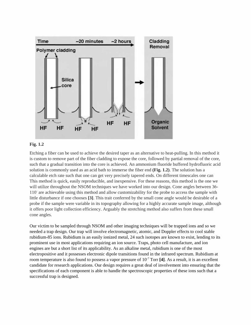
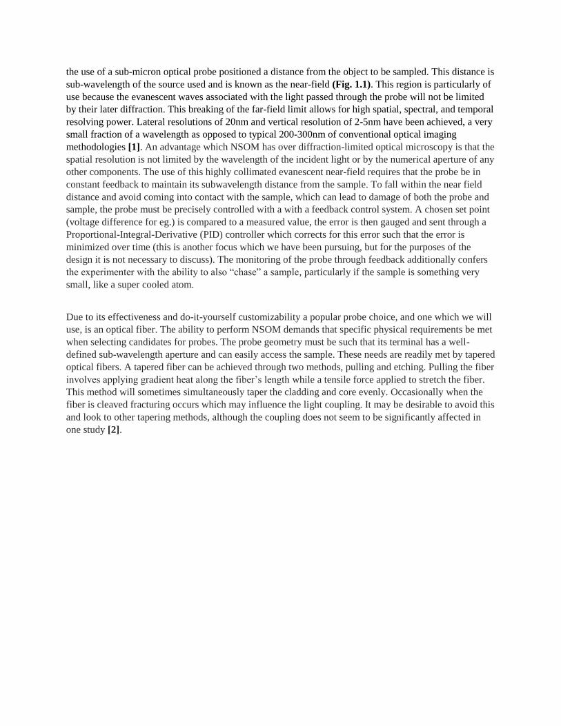
Fig. 1.2
Etching a fiber can be used to achieve the desired taper as an alternative to heat-pulling. In this method it
is custom to remove part of the fiber cladding to expose the core, followed by partial removal of the core,
such that a gradual transition into the core is achieved. An ammonium fluoride buffered hydrofluoric acid
solution is commonly used as an acid bath to immerse the fiber end (Fig. 1.2). The solution has a
calculable etch rate such that one can get very precisely tapered ends. On different timescales one can
This method is quick, easily reproducible, and inexpensive. For these reasons, this method is the one we
will utilize throughout the NSOM techniques we have worked into our design. Cone angles between 36󠅣-
110◦ are achievable using this method and allow customizability for the probe to access the sample with
little disturbance if one chooses [3]. This trait conferred by the small cone angle would be desirable of a
probe if the sample were variable in its topography allowing for a highly accurate sample image, although
it offers poor light collection efficiency. Arguably the stretching method also suffers from these small
cone angles.
Our victim to be sampled through NSOM and other imaging techniques will be trapped ions and so we
needed a trap design. Our trap will involve electromagnetic, atomic, and Doppler effects to cool stable
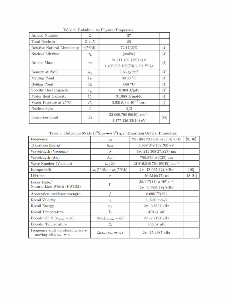
rubidium-85 ions. Rubidium is an easily ionized metal, 24 such isotopes are known to exist, lending to its
prominent use in most applications requiring an ion source. Traps, photo cell manufacture, and ion
engines are but a short list of its applicability. As an alkaline metal, rubidium is one of the most
electropositive and it possesses electronic dipole transitions found in the infrared spectrum. Rubidium at
room temperature is also found to possess a vapor pressure of 10-7 Torr [4]. As a result, it is an excellent
candidate for research applications. Our design requires a great deal of involvement into ensuring that the
specifications of each component is able to handle the spectroscopic properties of these ions such that a
successful trap is designed.
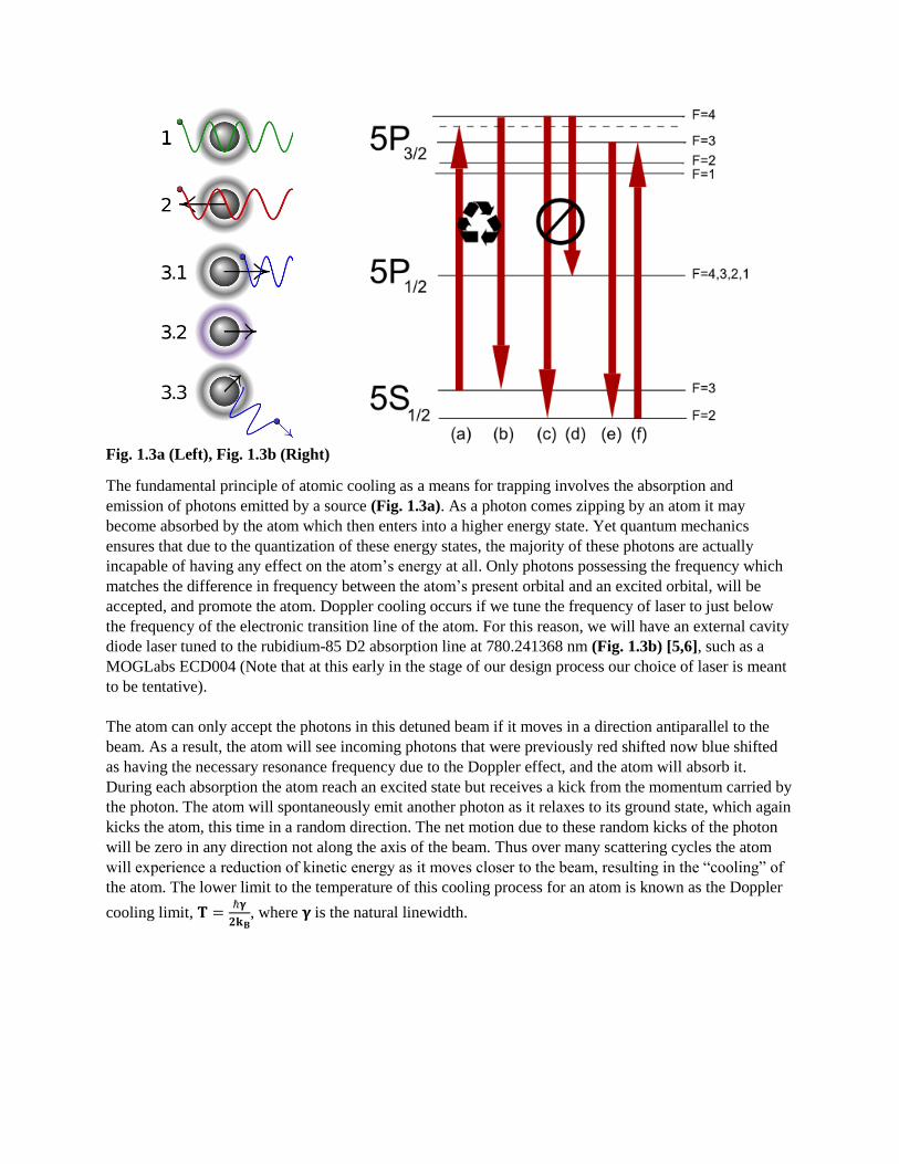
Fig. 1.3a (Left), Fig. 1.3b (Right)
The fundamental principle of atomic cooling as a means for trapping involves the absorption and
emission of photons emitted by a source (Fig. 1.3a). As a photon comes zipping by an atom it may
become absorbed by the atom which then enters into a higher energy state. Yet quantum mechanics
ensures that due to the quantization of these energy states, the majority of these photons are actually
incapable of having any effect on the atom’s energy at all. Only photons possessing the frequency which
matches the difference in frequency between the atom’s present orbital and an excited orbital, will be
accepted, and promote the atom. Doppler cooling occurs if we tune the frequency of laser to just below
the frequency of the electronic transition line of the atom. For this reason, we will have an external cavity
diode laser tuned to the rubidium-85 D2 absorption line at 780.241368 nm (Fig. 1.3b) [5,6], such as a
MOGLabs ECD004 (Note that at this early in the stage of our design process our choice of laser is meant
to be tentative).
The atom can only accept the photons in this detuned beam if it moves in a direction antiparallel to the
beam. As a result, the atom will see incoming photons that were previously red shifted now blue shifted
as having the necessary resonance frequency due to the Doppler effect, and the atom will absorb it.
During each absorption the atom reach an excited state but receives a kick from the momentum carried by
the photon. The atom will spontaneously emit another photon as it relaxes to its ground state, which again
kicks the atom, this time in a random direction. The net motion due to these random kicks of the photon
will be zero in any direction not along the axis of the beam. Thus over many scattering cycles the atom
will experience a reduction of kinetic energy as it moves closer to the beam, resulting in the “cooling” of
the atom. The lower limit to the temperature of this cooling process for an atom is known as the Doppler
cooling limit, 𝐓 =ℏ𝛄
𝟐𝐤𝐁, where 𝛄 is the natural linewidth.
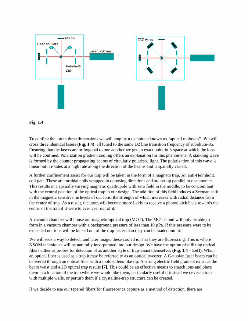
Fig. 1.4
To confine the ion in three dimensions we will employ a technique known as “optical molasses”. We will
cross three identical lasers (Fig. 1.4), all tuned to the same D2 line transition frequency of rubidium-85.
Ensuring that the lasers are orthogonal to one another we get an exact point in 3-space at which the ions
will be confined. Polarization gradient cooling offers an explanation for this phenomena. A standing wave
is formed by the counter propagating beams of circularly polarized light. The polarization of this wave is
linear but it rotates at a high rate along the direction of the beams and is spatially varied.
A further confinement assist for our trap will be taken in the form of a magneto trap. An anti-Helmholtz
coil pair. These are toroidal coils wrapped in opposing directions and are set up parallel to one another.
This results in a spatially varying magnetic quadrupole with zero field in the middle, to be concomitant
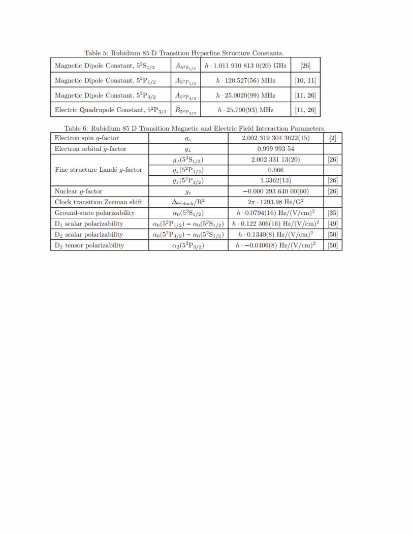
with the central position of the optical trap in our design. The addition of this field induces a Zeeman shift
in the magnetic sensitive mf levels of our ions, the strength of which increases with radial distance from
the center of trap. As a result, the atom will become more likely to receive a photon kick back towards the
center of the trap if it were to ever veer out of it.
A vacuum chamber will house our magneto-optical trap (MOT). The MOT cloud will only be able to
form in a vacuum chamber with a background pressure of less than 10 µPa. If this pressure were to be
exceeded our ions will be kicked out of the trap faster than they can be loaded into it.
We will seek a way to detect, and later image, these cooled ions as they are fluorescing. This is where
NSOM techniques will be naturally incorporated into our design. We have the option of utilizing optical
fibers either as probes for detection of as another style of trap-assist themselves (Fig. 1.4 – Left). When
an optical fiber is used as a trap it may be referred to as an optical tweezer. A Gaussian laser beam can be
delivered through an optical fiber with a molded lens-like tip. A strong electric field gradient exists at the
beam waist and a 2D optical trap results [7]. This could be an effective means to snatch ions and place
them in a location of the trap where we would like them, particularly useful if instead we devise a trap
with multiple wells, or perturb them if a crystalline-trap structure can be created.
If we decide to use our tapered fibers for fluorescence capture as a method of detection, there are
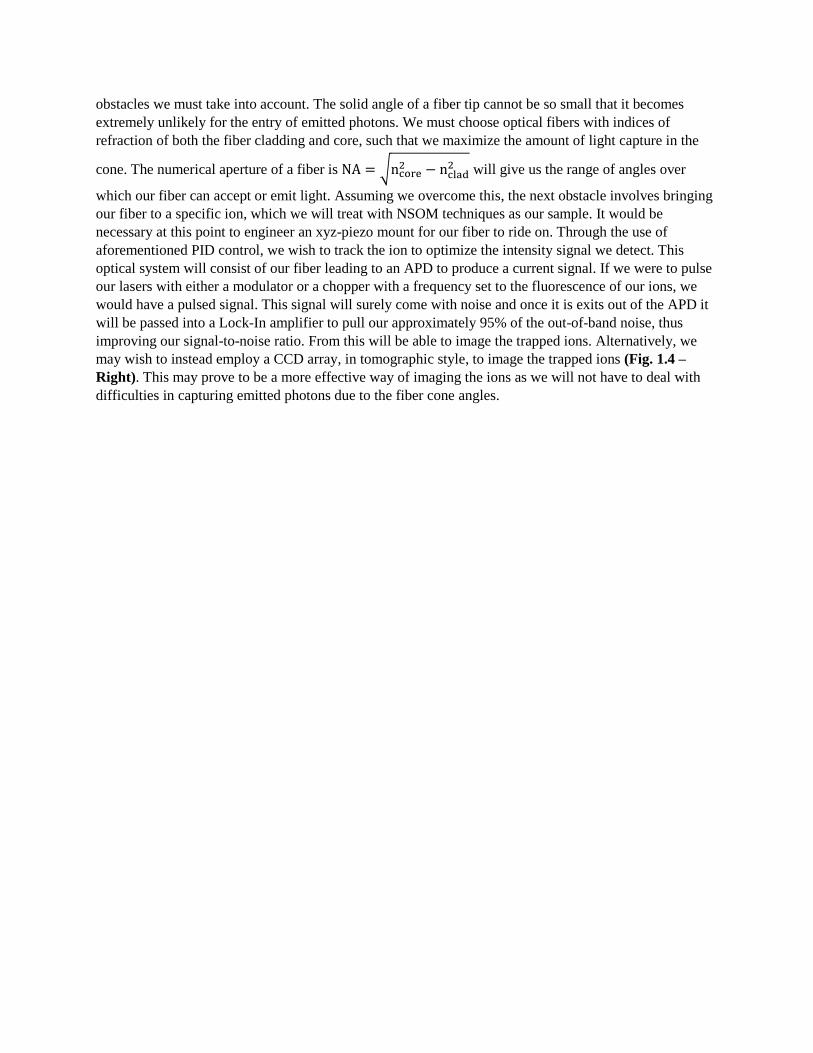
obstacles we must take into account. The solid angle of a fiber tip cannot be so small that it becomes
extremely unlikely for the entry of emitted photons. We must choose optical fibers with indices of
refraction of both the fiber cladding and core, such that we maximize the amount of light capture in the
cone. The numerical aperture of a fiber is NA = √ncore2 − nclad
2 will give us the range of angles over
which our fiber can accept or emit light. Assuming we overcome this, the next obstacle involves bringing
our fiber to a specific ion, which we will treat with NSOM techniques as our sample. It would be
necessary at this point to engineer an xyz-piezo mount for our fiber to ride on. Through the use of
aforementioned PID control, we wish to track the ion to optimize the intensity signal we detect. This
optical system will consist of our fiber leading to an APD to produce a current signal. If we were to pulse
our lasers with either a modulator or a chopper with a frequency set to the fluorescence of our ions, we
would have a pulsed signal. This signal will surely come with noise and once it is exits out of the APD it
will be passed into a Lock-In amplifier to pull our approximately 95% of the out-of-band noise, thus
improving our signal-to-noise ratio. From this will be able to image the trapped ions. Alternatively, we
may wish to instead employ a CCD array, in tomographic style, to image the trapped ions (Fig. 1.4 –
Right). This may prove to be a more effective way of imaging the ions as we will not have to deal with
difficulties in capturing emitted photons due to the fiber cone angles.
References
[1] Dürig, U.; et al. (1986). "Near-field optical scanning microscopy". J. Appl. Phys. 59 (10): 3318.)
[2] Sarangan, A. M. (2007). Tapering Optical Fibers. Retrieved December 09, 2016, from
https://udayton.edu/directory/engineering/electrooptics_grad/sarangan_andrew.php
[3] (Puygranier, B., & Dawson, P. (2000). Chemical etching of optical fibre tips — experiment and model.
Ultramicroscopy, 85(4), 235-248. doi:10.1016/s0304-3991(00)00069-3)
[4] Robinson, J., Liu, Y., & Shelton, D. (2014). Development and Characterization of a Magneto-Optical
Trap for Rubidium. Nevada State Undergraduate Research Journal, 1(1), 14-21.
doi:10.15629/6.7.8.7.5_1-1_f-2014_2
[5] Steck, D. A. (n.d.). Rubidium 85 D Line Data. Retrieved from
http://steck.us/alkalidata/rubidium85numbers.pdf
[6] Gardiner, S. (n.d.). Rubidium D2 Line. Retrieved December 09, 2016, from
http://massey.dur.ac.uk/gtp/RbD2line/RbD2line.html
[7] Single-beam optical fiber trap. (2007). Journal of Physics: Conference Series, 61, 1137-1141.
doi:10.1088/1742-6596/61/1/225

Appendix
MOGLabs External Cavity Diode Laser: Model ECD004
Wavelength/frequency
780 nm 60 mW standard. Up to 200 mW output power available.
369.5-1120 nm Contact MOGLabs.
Linewidth Typically 200kHz FWHM (self-heterodyne)
RF modulation 160 kHz – 2.5 GHz
Grating Standard: 1800 l/mm holographic Au
Tuning range Typically +/-5 nm for single diode 369 nm to 980 nm with different diodes.
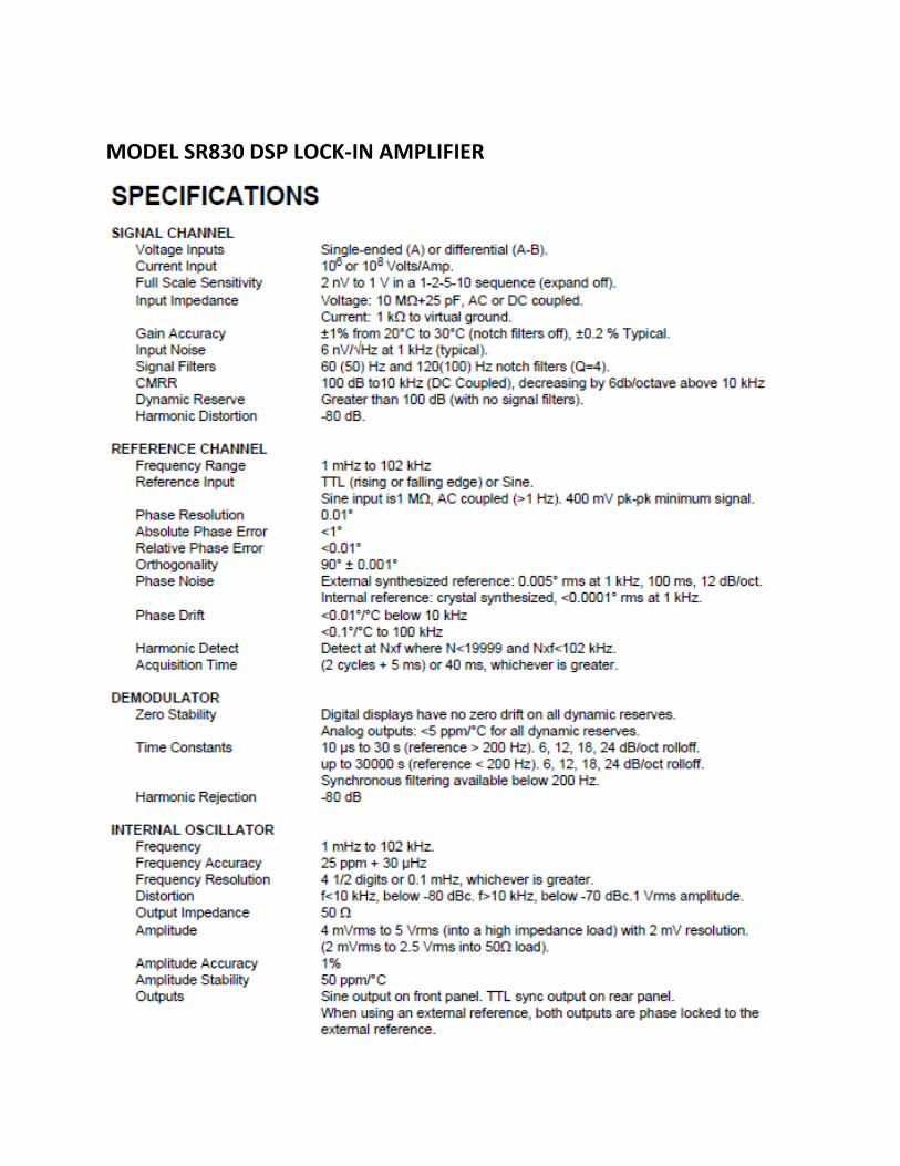
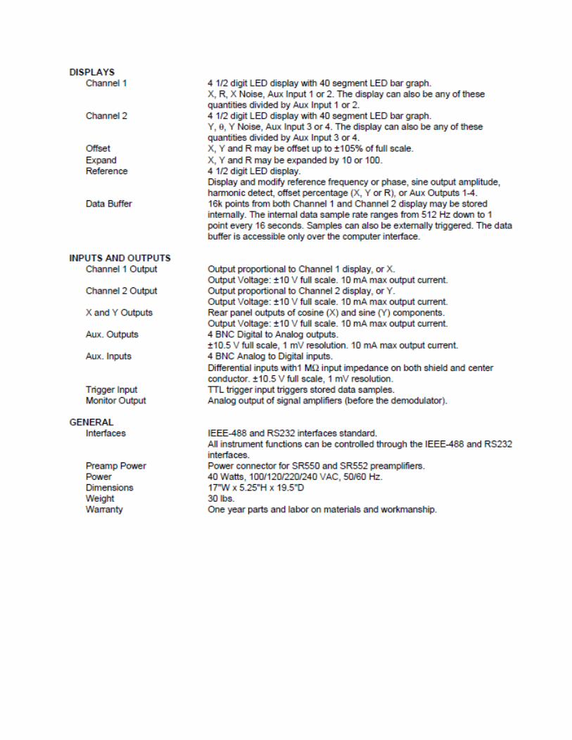
MODEL SR830 DSP LOCK-IN AMPLIFIER