optical solitons from a photonic crystal fiber and their applications
TRANSCRIPT
0
Optical Solitons from a Photonic Crystal Fiberand Their Applications
Naoki Karasawa and Kazuhiro TadaChitose Institute of Science and Technology
Japan
1. Introduction
A photonic crystal fiber (PCF) is a fiber that contains the regular (usually hexagonal) arraysof air holes in the propagation direction of an optical fiber. At the center position, the coreis created by not making an air hole and the light wave propagates at the core positionsince the effective refractive index of the core is higher than that of the photonic crystalclad surrounding the core. Photonic crystal fibers of this type have been used to generateultrabroadband optical pulses by propagating femtosecond optical pulses in these fibers(Ranka et al., 2000). The core diameter of a PCF for the generation of ultrabroadbandoptical pulses using a Ti:sapphire laser (center wavelength ∼800 nm) is about 1-2 µm if itis assumed that the silica core is surrounded by regular air holes. Due to the waveguidedispersion, the group velocity dispersion (GVD) becomes negative at 800 nm. Because ofthe small core diameter and the negative GVD, nonlinear effects are enhanced and opticalsolitons are generated in a PCF. Theoretical calculations for elucidating the mechanism ofthe ultrabroadband pulse generation in a PCF have been performed (Husakou & Herrmann,2001) and the generation of fundamental soliton pulses by the fission of an input higher-ordersoliton pulse due to the third and higher order dispersion as well as the higher-ordernonlinear effects including the Raman effects are found to be important for the spectralbroadening. Supercontinuum generation in a PCF is reviewed in (Dudley et al., 2006). Thecenter wavelength of the generated fundamental soliton pulse becomes longer as it propagatesin a PCF due to soliton self-frequency shift and its center wavelength can be changed by thepeak power or the chirp of an input pulse. Recently, it was used as a variable-wavelengthlight source in various applications including coherent anti-Stokes Raman scattering (CARS)spectroscopy and optical coherence tomography (OCT). The present article describes theproperties of the fundamental solitons from a PCF and its applications studied in ourlaboratory.
2. Fundamental soliton pulse
It is well known that the soliton pulse, which does not change its shape as it propagates in afiber, can be created when the pulse propagates in the anomalous dispersion region (Agrawal,2007; Hasegawa, 1992). If we consider the electric field (considered to be scalar) that depends
on only time t and propagation position z such that E(z, t) = Re[A(z, t)ei(β0z−ω0t)], where Reshows the real part, ω0 is the central angular frequency, and β0 is the propagation constant atω0 (β0 = β(ω0)) of a pulse, the slowly varying envelope approximation (SVEA) equation for
10
www.intechopen.com

2 Will-be-set-by-IN-TECH
the envelope A(z, t) (normalized to have the unit [W1/2]) may be obtained from the Maxwellequation after various approximations (Karasawa et al., 2001) as follows,
∂ζ A(ζ, T) = − i
2β(2)0 ∂2
T A(ζ, T) + iγ(ω0)|A(ζ, T)|2 A(ζ, T). (1)
In this equation, the coordinates are transformed ζ = z, T = t − β(1)0 z such that the pulse
center is always at the time origin (β(1)0 = ∂ω β|ω0 is the inverse of the group velocity
of the pulse). In the right hand side of Eq. 1, the first term arises from the dispersion,
where the GVD is given by β(2)0 = ∂2
ω β|ω0 . The second term arises from the nonlinearself-phase modulation (SPM) with the frequency-dependent nonlinear coefficient γ(ω0) =n(ω0)n
I2(ω0)ω
20(1 − fR)/(c
2β0 Aeff(ω0)), where n(ω0) and nI2(ω0) are the linear and the
nonlinear indices of refraction of a medium, c is the speed of light, Aeff(ω0) is the effectivemode area in a fiber, and fR is the contribution of the Raman term ( fR ≃ 0.3 for fusedsilica). When the GVD is negative and the input power is chosen appropriately, the effectsof these terms on the variations of the envelope cancel, and a stable soliton pulse can bepropagated. By changing the variables to dimensionless ones such that ξ = ζ/LD, τ = T/T0,
u(ξ, τ) =√
γ(ω0)LD A(ξ, τ) (Agrawal, 2007), where T0 is the pulse width parameter, and
LD = T20 /|β(2)0 | is the dispersion length, we have
∂ξ u(ξ, τ) =i
2∂2
τu(ξ, τ) + i|u(ξ, τ)|2u(ξ, τ), (2)
when β(2)0 < 0. This equation was solved by the inverse scattering method and has a
fundamental soliton solution of a form (Agrawal, 2007)
u(ξ, τ) = η sech η(τ + δξ − τs)e−iδτ+i(η2−δ2)ξ/2+iφs, (3)
where η and δ are determined by the eigenvalue of the inverse scattering problem, and τs
and φs are constants. Here, φs can be included in an initial carrier wave phase, and δ and τs
can be eliminated by shifting the carrier center frequency and the initial temporal position of
the pulse. Therefore it can be written as u(ξ, τ) = η sech (ητ)eiη2ξ/2, which shows that theenvelope intensity does not change as it propagates in a fiber. The parameter η determinesboth the amplitude and the width of the soliton pulse. If the pulse width is T0, η = 1 andthe solution is given simply by u(ζ, τ) = sech (τ)eiξ/2. If the input pulse shape of a laseris approximated as u(0, τ) = B sech τ, the number of eigenvalues N is given by B − 1/2 <
N ≤ B + 1/2 (Satsuma & Yajima, 1974). For an input pulse envelope with a peak power
P0, A(0, T) =√
P0 sech (T/T0) and this "soliton number" B becomes B =√
P0γ(ω0)LD =√
P0γ(ω0)T20 /|β(2)0 |. If B is exactly equal to N, the solution can be obtained in terms of N
amplitudes ηj = 1, 3, 5, ..., (2N − 1). For N ≥ 2, higher-order N-soliton solutions were found(Satsuma & Yajima, 1974; Schrader, 1995). These N-soliton solutions may be considered to beconsisted of N single solitons (Schrader, 1995).
In the real fiber of our interest, neglected terms deriving Eq. 1, such as higher-orderdispersion terms, self-steepening terms, and the Raman term become important. If we usea slowly-evolving wave approximation (SEWA) instead of SVEA, the following propagation
202 Photonic Crystals – Introduction, Applications and Theory
www.intechopen.com
Optical Solitons from a Photonic Crystal Fiber and Their Applications 3
equation can be derived (Karasawa et al., 2001),
∂ζ A(ζ, T) = i(D̂′ + D̂corr)A(ζ, T) + iγ′(ω0)(1 + is∂T)[
(1 − fR)|A(ζ, T)|2
+2
3fR
∫ ∞
0hR(T
′)|A(ζ, T′)|2dT′]
A(ζ, T), (4)
where
D̂′ =∞
∑n=0
in
n!
(
∂nω(β(ω) +
iα(ω)
2)|ω0
)
∂nT − β0 − iβ
(1)0 ∂T , (5)
is the dispersion terms that contain all higher-order terms with α(ω) to be the loss constant,
D̂corr = (1+ iβ(1)0 ∂T/β0)
−1D̂′2/(2β0) is the dispersion correction term, s = 2/ω0 − β(1)0 /β0 +
∂ω(log(n(ω)nI2(ω)/Aeff(ω)))|ω0 is the self-steepening term, γ′(ω0) = γ(ω0)/(1 − fR), and
hR(T) = (τ21 + τ2
2 )e−T/τ2 sin(T/τ1)/(τ1τ2
2 ) is the response function of the delayed Ramanresponse with τ1 = 12.2 fs and τ2 = 32 fs for fused silica (Blow & Wood, 1989).
Because of the presence of extra terms not included in Eq. 1, the inputted pulse withu(0, τ) = B sech τ separates to multiple soliton pulses if the amplitude B > 1.5. Themain reason of the splitting is the self-frequency shift due to the Raman effect (Gordon, 1986;Mitschke & Mollenauer, 1986), which depends on the pulse amplitude and width. If the centerfrequency is changed, the temporal delay of the pulse changes due to the dispersive effect (D̂′
term). Independently, it is modified by the self-steepening effect (s term). The effects of thesehigher-order terms were investigated by moments equations for pulse parameters (Agrawal,2007), where the variations of pulse parameters (pulse width, chirp, delay, and center angularfrequency) were calculated as functions of propagation distance z. The variation of the centerfrequency of the fundamental soliton (N = 1) without a chirp can be approximated as
ω0(z) = − 8TRγ(ω0)P0
15T20
z = − 8TR|β(2)0 |15T4
0
z, (6)
where TR is the first moment of the Raman response function, TR ≃ fR
∫ ∞
0 thR(t)dt = 2.4 fsfor fused silica. This wavelength-variable fundamental soliton pulse emits a phase-matcheddispersive wave, which is the important mechanism for generating supercontinuum,especially for shorter wavelength components (Husakou & Herrmann, 2001).
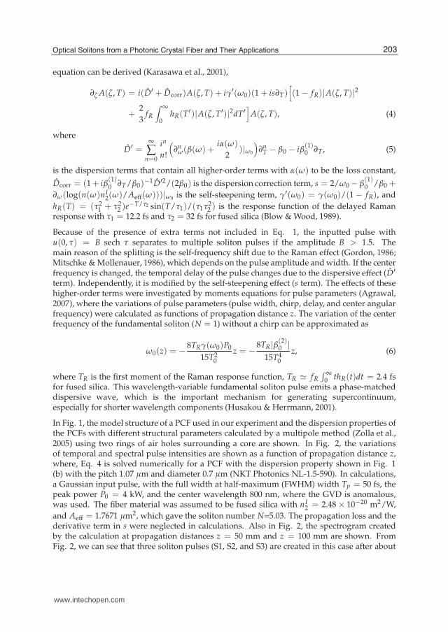
In Fig. 1, the model structure of a PCF used in our experiment and the dispersion properties ofthe PCFs with different structural parameters calculated by a multipole method (Zolla et al.,2005) using two rings of air holes surrounding a core are shown. In Fig. 2, the variationsof temporal and spectral pulse intensities are shown as a function of propagation distance z,where, Eq. 4 is solved numerically for a PCF with the dispersion property shown in Fig. 1(b) with the pitch 1.07 µm and diameter 0.7 µm (NKT Photonics NL-1.5-590). In calculations,a Gaussian input pulse, with the full width at half-maximum (FWHM) width Tp = 50 fs, thepeak power P0 = 4 kW, and the center wavelength 800 nm, where the GVD is anomalous,was used. The fiber material was assumed to be fused silica with nI
2 = 2.48 × 10⁻²⁰ m2/W,
and Aeff = 1.7671 µm2, which gave the soliton number N=5.03. The propagation loss and thederivative term in s were neglected in calculations. Also in Fig. 2, the spectrogram createdby the calculation at propagation distances z = 50 mm and z = 100 mm are shown. FromFig. 2, we can see that three soliton pulses (S1, S2, and S3) are created in this case after about
203Optical Solitons from a Photonic Crystal Fiber and Their Applications
www.intechopen.com
4 Will-be-set-by-IN-TECH
z = 25 mm. The center frequency of the most intense fundamental soliton (S1) decreases untilz = 150 mm, where GVD becomes zero. Because of this frequency shift, the group velocitydecreases and the delay time becomes about 1000 fs at z = 100 mm. The pulse width, thespectral bandwidth, and the peak power of the most intense soliton are 14 to 18 fs, 60 to 65nm, and 5 to 7 kW, respectively. Thus, this wavelength-variable fundamental soliton pulse hasa shorter pulse width and a higher peak power compared with the inputted pulse. This solitonpulse emits a dispersive wave (D1) at the short wavelength near 550 nm, where the GVD ispositive and its delay time increases quite rapidly. It is observed that there is a dispersivewave (D2) near 1400 nm after z = 150 mm. The intensities of other two soliton pulses (S2 andS3) are much weaker than the first soliton pulse (S1). The shift of the center frequency of thethird soliton (S3) is small since its peak power is small. Also, it has a negative delay time sinceits center wavelength is shorter than 800 nm. From the spectrograms (c) and (d), we can seethat three waves marked by S1, S2, and S3 are indeed localized pulses.
d
400 600 800 1000 1200 1400 1600 1800200
150
100
50
0
50
100
150
200
250
1.95
2
2.05
GV
D (
fs2/m
m)
wavelength (nm)
PCF2 NL 1.5 670
PCF1 NL 1.5 590
vg
(10
8m
/s)
PCF3 PSTI PCF
(a) (b)
Fig. 1. (a) The structure of a five-ring PCF with a pitch Λ and a diameter d. Gray areas show
air holes. (b) The GVD and the group velocity (vg = 1/β(1)) of the PCF shown in (a)calculated by a multipole method with various parameters. Blue curves show NKTPhotonics NL-1.5-590 (Λ = 1.07µm, d = 0.7µm), red curves show NKT Photonics NL-1.5-670(Λ = 1.3µm, d = 1.105µm), and green curves show PSTI-PCF (Λ = 1.57µm, d = 1.31µm).
3. Experiment on soliton properties
3.1 Soliton wavelength versus delay time
In the previous section, it is shown from calculations that an intense fundamental solitonpulse can be obtained by inputting a femtosecond pulse into a PCF and its center wavelengthchanges during propagation. However, in usual experiment, the length of a PCF is fixed andthe center wavelength is controlled by modifying the input pulse parameters. In this section,the control of the center wavelength by the input pulse power and the delay property of asoliton are described.
As shown in Eq. 6, the variation of the center angular frequency due to self-frequency shiftof a soliton pulse can be approximated to be proportional to the propagation distance z. Thisproportionality constant contains the peak power P0 of the soliton pulse. Thus it is expected
204 Photonic Crystals – Introduction, Applications and Theory
www.intechopen.com

Optical Solitons from a Photonic Crystal Fiber and Their Applications 5
S1
S1
S2
S2S3S3
D1
D1
D2
0 500 1000 0.2 0.3 0.4 0.5 0.6
time (fs) frequency (PHz)
1500 1000 750 600 500
wavelength (nm)
0.3
0.2
0.1
0
0.3
0.2
0.1
0
length
(m
)
10
10
10
10
-3
-2
-1
0
length
(m
)
(a) (b)
0 1000 0 1000
0.2 0.2
0.4 0.4
0.60.6
time (fs) time (fs)
freq
uen
cy (
PH
z)
freq
uen
cy (
PH
z)
S1 S1
D1 D1
S2 S2
S3 S3
(c) (d)
500 500
750750
1500 1500
wav
elen
gth
(n
m)
wav
elen
gth
(n
m)
Fig. 2. The calculated temporal (a) and spectral (b) intensities of an optical pulse inputted in aPCF (NKT Photonics NL-1.5-590) versus distance. In (c) and (d), spectrograms at z = 50 mm(c) and z = 100 mm (d) are shown. S1, S2, and S3 show fundamental soliton pulses. D1 andD2 show the dispersive waves emitted from a soliton S1. The intensities are shown in alogarithmic scale.
that the amount of the shift is proportional to the power of the input pulse approximately. Ifthe variation of the center angular frequency is proportional to the distance, the delay timeof the soliton at the output end of a PCF can be estimated as follows. The propagation timeT(ω0o) of a soliton with the angular frequency ω0o at the output end of a PCF with a length Lis given by
T(ω0o) =∫ L
0β(1)dz =
1
K
∫ ω0o
ω0i
β(1)dω =1
K(β(ω0o)− β(ω0i)), (7)
where ω0i is the center angular frequency at the input end and K is the proportional constant,which is given by K = (ω0o − ω0i)/L. Thus, we have
T(ω0o) =β(ω0o)− β(ω0i)
ω0o − ω0iL. (8)
This equation shows that the delay time of the soliton for various center wavelengths can beestimated by the propagation constant β(ω) only. We have performed experiment to examine
205Optical Solitons from a Photonic Crystal Fiber and Their Applications
www.intechopen.com
6 Will-be-set-by-IN-TECH
0 20 40 60
20
40
60
80
800 900 1000 1100
0
0.5
1
1.5
frequency shift (THz)
inp
ut
po
wer
(m
W)
PCF1 NL−1.5−590 120 mm
PCF2 NL−1.5−670 114 mm
PCF3 PSTI−PCF 127 mm
del
ay t
ime
(fs)
wavelength (nm)
PCF2 NL−1.5−670 114 mm
PCF1 NL−1.5−590 120 mm
PCF3 PSTI−PCF 127 mm
(a) (b)
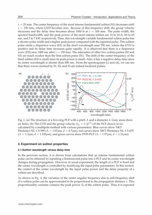
Fig. 3. (a) Frequency shift versus input power of soliton pulses for three different PCFs. (b)Wavelength versus delay time of soliton pulses for three different PCFs. Solid curves showdelay times calculated by Eq. 8.
the dependence of the center wavelength and the delay time on the input power for threedifferent PCFs, where the dispersion properties are shown in Fig. 1 (b). In experiment, a pulsefrom a Ti:sapphire laser oscillator (center wavelength 800 nm, pulse width 50 fs, repetitionrate 78 MHz, and average power 620 mW) was propagated in PCFs, where the average powerwas controlled by a variable neutral density filter. In Fig. 3 (a), the frequency shifts of the mostintense soliton pulses versus input pulse power are shown, where the shifts at 875 nm were setto be 0. As expected, the frequency shifts are almost proportional to the input pulse power forthree different PCFs. In Fig. 3 (b), the delay times of the soliton pulses versus wavelength areshown and compared with delay times given in Eq. 8, where the delay times at 875 nm wereset to be 0 and ω0i was set to be 2πc/(800 nm). It is seen that the approximate delay timesfor the PCFs were estimated correctly. The discrepancies are presumably due to the neglect ofdelay times required for the soliton fission near the input ends of the PCFs in Eq. 8.
PCF
LPFIR Spectrometer
Ti:sapphire laser
800 nm, 78 MHz
50 fs, 620 mW
VND 60× 40×
d
0
33.5
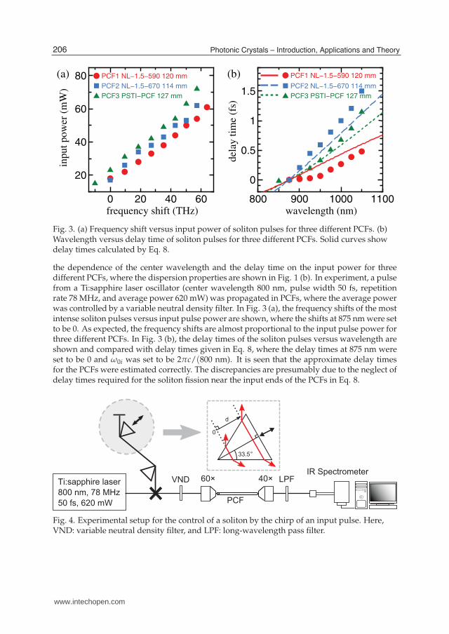
Fig. 4. Experimental setup for the control of a soliton by the chirp of an input pulse. Here,VND: variable neutral density filter, and LPF: long-wavelength pass filter.
206 Photonic Crystals – Introduction, Applications and Theory
www.intechopen.com

Optical Solitons from a Photonic Crystal Fiber and Their Applications 7
3.2 Soliton wavelength control by chirp
We have studied the control of the soliton center wavelengths by the chirp of an input pulse(Karasawa et al., 2007; Tada & Karasawa, 2008). In experiment, the chirp of an input pulse waschanged by varying the position of one of the prisms in a prism pair and the spectrum andthe delay time of an output pulse from the PCF were measured. Experimental setup is shownin Fig. 4. A pulse from a Ti:sapphire laser oscillator (the center wavelength, the pulse width,and the repetition rate of the laser were 800 nm, 50 fs, and 78 MHz, respectively) was inputtedinto the PCF. A pair of Brewster-cut BK7 prisms was used to compensate for the dispersionof the objective and to apply the chirp for the PCF. When the insertion length was set to be das shown in Fig. 4, the value of the group delay dispersion (GDD) was 4β2d tan 33.5◦ , whereβ2 = 44.7 fs2/mm is the GVD of BK7 at 800 nm. The chirp factor C due to this GDD was
given by C = β2d/T20 . Due to this chirp, the pulse width was increased by a factor of
√1 + C2
(Agrawal, 2007) and the peak power P0 of the pulse was reduced by the same factor sincethe pulse energy was kept constant. Thus, the electric field envelope of the pulse may be
written as a Gaussian form to be A(T) =√
P0e−(1+iC)T2/(2T20 ), where T0 = 50/1.665 fs and
this functional form was used in the calculations using Eq. 4 later in this subsection.
In the first experiment, PCFs (NKT Photonics NL-1.5-670) with three different lengths (62,114, and 166 mm) were used. The center wavelength of a fundamental soliton pulse versusan input pulse power is shown in Fig. 5 (a) and compared with the center wavelength versusan input pulse chirp shown in Fig. 5 (b). Also, the delay time versus the center wavelengthof a fundamental soliton pulse is shown in Fig. 5 (c). As shown in this figure, the centerwavelength of a fundamental soliton pulse changes quadratically when a fiber length was 62mm. Similar results are obtained for 114 mm and 166 mm, although some discrepancies arenoted. From Fig. 5 (c), it is seen that for the same PCF length, the delay time is independenton the control method and its dependence on wavelength is linear. Also it is shown thatthe delay time decreases as the fiber length becomes shorter. In the second experiment, a
900 950 100010500
50
100
900 950 10001050
0
1
900 950 10001050
−2
−1
0
wavelength (nm)
inp
ut
po
wer
(m
W) 166 mm
114 mm
62 mm
wavelength (nm)
chir
p f
acto
r
wavelength (nm)
del
ay t
ime
(ps)
166 mm
114 mm
62 mm
166 mm
114 mm
62 mm
(a) (b) (c)
Fig. 5. Wavelength versus input power (a), wavelength versus chirp factor (b), andwavelength verses delay time (c) of soliton pulses for PCFs with different lengths.
166-mm-long PCF (NKT Photonics NL-1.5-670) whose calculated dispersion is shown in Fig.1 (b) was used, and the results from experiment and calculations were compared. In Fig. 6(a), experimental spectrum at 40 mW input average power is shown. There are two peaksat wavelengths near 860 nm and near 1030 nm and these correspond to fundamental solitonpulses created by the fission of an input pulse. The peak near 450 nm is a dispersive waveemitted by fundamental soliton pulses. In Fig. 6 (b), calculated spectrum at 5.74 kW input
207Optical Solitons from a Photonic Crystal Fiber and Their Applications
www.intechopen.com

8 Will-be-set-by-IN-TECH
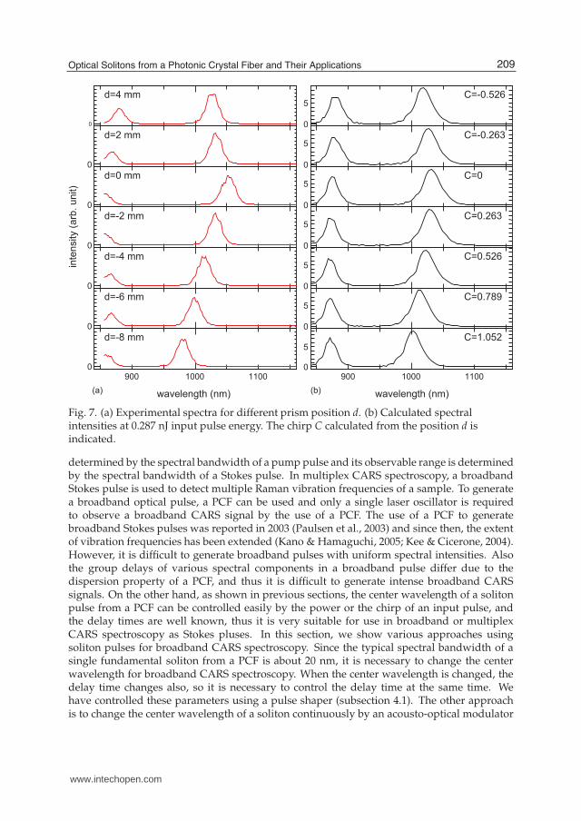
peak power, 50 fs pulse width, and C = 0 is shown. The experimental and calculated spectraagreed very well as shown in this figure. The temporal waveform (Fig. 6 (c)) shows twofundamental soliton pulses at ∼0.9 ps and at ∼3.6 ps. In Fig. 7, the experimental variationof the spectral peak positions of fundamental soliton pulses is shown for different prismposition d. As shown in this figure, the peak position of the fundamental soliton pulse atlongest wavelength changed about 70 nm according to d. In Fig. 6, the calculated spectraland temporal intensities are shown for different chirp C calculated from d in Fig. 4. The pulseenergy in these calculations was set to be 0.287 nJ, which corresponded to 5.74 kW peak powerat C = 0. The calculated spectra showed the almost identical variation of peak positionscompared with experiment. As the absolute value of C was increased, the temporal positionof the most intense fundamental soliton pulse became smaller and the corresponding spectralpeak wavelength became shorter. It means that as the absolute value of C was increased,the timing of the fission of an input pulse was delayed more and as a result of this, thefundamental soliton pulses experienced less soliton self-frequency shifts and less delay timesat the output end of the PCF.
0
10
400 500 600 700 800 900 1000 1100 1200
0
5
-2 -1 0 1 2 3 4
0
1
wavelength (nm)
inte
nsity (
arb
. unit)
(a)
(b) (c)
time (ps)
Fig. 6. (a) Experimental spectrum at 40 mW input power. Calculated spectral intensity (b)and temporal intensity (c) when a pulse with 5.74 kW peak power is inputted into a PCF.
4. Solitons for coherent anti-Stokes Raman scattering spectroscopy
Coherent anti-Stokes Raman scattering (CARS) microscopic spectroscopy is one of thenonlinear optical spectroscopy that has attracted attention recently (Cheng & Xie, 2004;Müller & Zumbusch, 2007). In CARS spectroscopy, a pump pulse (angular frequency ωp)and a Stokes pulse (angular frequency ωs) are used to illuminate a sample to generate ananti-Stokes signal (angular frequency 2ωp − ωs). This signal is enhanced when the frequencydifference between the pump and the Stokes pulses (ωp − ωs) coincides one of the Ramanactive vibration frequencies of the sample. The CARS signal is coherent and its intensityis much higher than that of a spontaneous Raman signal. Also, CARS signals from afluorescent sample can be detected because the frequencies of CARS signals are higher thanthe frequencies of fluorescent signals. When CARS signals are detected in a microscope,the spatial resolution is expected to be high because the CARS signals are generated due tothird-order nonlinear optical processes. The spectral resolution of a CARS signal is usually
208 Photonic Crystals – Introduction, Applications and Theory
www.intechopen.com
Optical Solitons from a Photonic Crystal Fiber and Their Applications 9
0
0
0
0
0
0
900 1000 11000
0
5
0
5
0
5
0
5
0
5
0
5
900 1000 11000
5
wavelength (nm)
inte
nsity (
arb
. unit)
d=4 mm
d=2 mm
d=0 mm
d=-2 mm
d=-4 mm
d=-6 mm
d=-8 mm
wavelength (nm)
C=-0.526
C=-0.263
C=0
C=0.263
C=0.526
C=0.789
C=1.052
(a) (b)
Fig. 7. (a) Experimental spectra for different prism position d. (b) Calculated spectralintensities at 0.287 nJ input pulse energy. The chirp C calculated from the position d isindicated.
determined by the spectral bandwidth of a pump pulse and its observable range is determinedby the spectral bandwidth of a Stokes pulse. In multiplex CARS spectroscopy, a broadbandStokes pulse is used to detect multiple Raman vibration frequencies of a sample. To generatea broadband optical pulse, a PCF can be used and only a single laser oscillator is requiredto observe a broadband CARS signal by the use of a PCF. The use of a PCF to generatebroadband Stokes pulses was reported in 2003 (Paulsen et al., 2003) and since then, the extentof vibration frequencies has been extended (Kano & Hamaguchi, 2005; Kee & Cicerone, 2004).However, it is difficult to generate broadband pulses with uniform spectral intensities. Alsothe group delays of various spectral components in a broadband pulse differ due to thedispersion property of a PCF, and thus it is difficult to generate intense broadband CARSsignals. On the other hand, as shown in previous sections, the center wavelength of a solitonpulse from a PCF can be controlled easily by the power or the chirp of an input pulse, andthe delay times are well known, thus it is very suitable for use in broadband or multiplexCARS spectroscopy as Stokes pluses. In this section, we show various approaches usingsoliton pulses for broadband CARS spectroscopy. Since the typical spectral bandwidth of asingle fundamental soliton from a PCF is about 20 nm, it is necessary to change the centerwavelength for broadband CARS spectroscopy. When the center wavelength is changed, thedelay time changes also, so it is necessary to control the delay time at the same time. Wehave controlled these parameters using a pulse shaper (subsection 4.1). The other approachis to change the center wavelength of a soliton continuously by an acousto-optical modulator
209Optical Solitons from a Photonic Crystal Fiber and Their Applications
www.intechopen.com
10 Will-be-set-by-IN-TECH
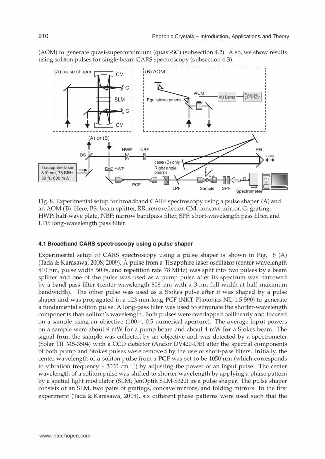
(AOM) to generate quasi-supercontinuum (quasi-SC) (subsection 4.2). Also, we show resultsusing soliton pulses for single-beam CARS spectroscopy (subsection 4.3).
NBF
PCF
RR
LPF Sample SPF
BS
Spectrometer
Ti:sapphire laser
810 nm, 78 MHz
50 fs, 600 mWz
xy
case (B) only
Right angleprisms
HWP
HWP
delay
G
G
SLM
CM
CM
AOM FunctiongeneratorAO Driver
Equilateral prisms
(A) or (B)
(A) pulse shaper (B) AOM
Fig. 8. Experimental setup for broadband CARS spectroscopy using a pulse shaper (A) andan AOM (B). Here, BS: beam splitter, RR: retroreflector, CM: concave mirror, G: grating,HWP: half-wave plate, NBF: narrow bandpass filter, SPF: short-wavelength pass filter, andLPF: long-wavelength pass filter.
4.1 Broadband CARS spectroscopy using a pulse shaper
Experimental setup of CARS spectroscopy using a pulse shaper is shown in Fig. 8 (A)(Tada & Karasawa, 2008; 2009). A pulse from a Ti:sapphire laser oscillator (center wavelength810 nm, pulse width 50 fs, and repetition rate 78 MHz) was split into two pulses by a beamsplitter and one of the pulse was used as a pump pulse after its spectrum was narrowedby a band pass filter (center wavelength 808 nm with a 3-nm full width at half maximumbandwidth). The other pulse was used as a Stokes pulse after it was shaped by a pulseshaper and was propagated in a 123-mm-long PCF (NKT Photonics NL-1.5-590) to generatea fundamental soliton pulse. A long-pass filter was used to eliminate the shorter-wavelengthcomponents than soliton’s wavelength. Both pulses were overlapped collinearly and focusedon a sample using an objective (100×, 0.5 numerical aperture). The average input powerson a sample were about 9 mW for a pump beam and about 4 mW for a Stokes beam. Thesignal from the sample was collected by an objective and was detected by a spectrometer(Solar TII MS-3504) with a CCD detector (Andor DV420-OE) after the spectral componentsof both pump and Stokes pulses were removed by the use of short-pass filters. Initially, thecenter wavelength of a soliton pulse from a PCF was set to be 1050 nm (which correspondsto vibration frequency ∼3000 cm−1) by adjusting the power of an input pulse. The centerwavelength of a soliton pulse was shifted to shorter wavelength by applying a phase patternby a spatial light modulator (SLM; JenOptik SLM-S320) in a pulse shaper. The pulse shaperconsists of an SLM, two pairs of gratings, concave mirrors, and folding mirrors. In the firstexperiment (Tada & Karasawa, 2008), six different phase patterns were used such that the
210 Photonic Crystals – Introduction, Applications and Theory
www.intechopen.com

Optical Solitons from a Photonic Crystal Fiber and Their Applications 11
0
10
0
10
850 900 950 1000 1050 1100
0
10
wavelength (nm)
inte
nsi
ty (
arb. unit
)
(a)
123
456
(b)
123
4
56
AB
C
D
E
F
(c)
Fig. 9. Spectra of soliton pulses obtained by a pulse shaper using quadratic (a), cosine (b),and pulse train (c) phase patterns. In (c), A–F correspond to soliton pulses generated bypulses A–F in pulse trains shown in Fig. 10.
spectra of soliton pulses covered the wavelength between 850 and 1050 nm uniformly. Twodifferent functional forms of phase patterns for varying the center wavelength of a soliton
pulse were tried. One was the quadratic phase pattern of a form (β(2)0 /2)(ω − ω0)
2, where
ω0 was the center angular frequency of an input pulse (ω0 = (2πc)/(800 nm)) and β(2)0
determined the chirp of an input pulse. The other was the cosine phase pattern of a formA cos ωT. When the cosine phase pattern was used, the pulse train of an original pulse wascreated with a period T and the peak amplitude of the central pulse was determined by theBessel function of zero order J0(A) (Morita & Toda, 2005). The period T was set to be 500 fsin experiment such that the timing of only the central pulse in a pulse train matched with a
pump pulse. In both cases, the phase pattern of a form β(1)0 (ω − ω0) was added to control
the delay time of an input pulse with respect to a pump pulse, where β(1)0 is a group delay.
Moreover, the phase pattern of a form (β(2)00 /2)(ω − ω0)
2 with β(2)00 = −200 fs2 was added for
all phase patterns to compensate for the dispersion of an objective lens in front of a PCF. To
adjust the delay time of a soliton pulse with a pump pulse, the group delay (β(1)0 ) of an input
pulse was set to be different for a soliton pulse with a different center wavelength. In Fig.9, the spectra of soliton pulses with six different center wavelengths are shown for both thequadratic (a) and the cosine (b) phase patterns. As shown in this figure, by using six solitonpulses with different center wavelengths, the spectral regions between 850 and 1050 nm werecovered almost uniformly. The exposure time to obtain CARS signals was set to be one secondfor each soliton pulse with a different wavelength, thus the total exposure time to obtain CARSsignals between 500 and 3100 cm−1 was six seconds. In addition to this, the switching time ofthe phase pattern in a SLM was required (about 0.3 second for every switching). In the later
211Optical Solitons from a Photonic Crystal Fiber and Their Applications
www.intechopen.com

12 Will-be-set-by-IN-TECH
0
0.5
1
−1500−1000−500 0 500 1000 1500
0
0.5
10
0.5
1
−1500−1000−500 0 500 1000 1500
0
0.5
1
time (fs)
inte
nsi
ty (
arb.
unit
)
AB
C
(a)
(c)
time (fs)
inte
nsi
ty (
arb.
unit
) F
DE
(b)
(d)
Fig. 10. Target pulse waveforms ((a) and (b)) for generating pulse train phase patterns andthe optimized waveforms ((c) and (d)).
experiment (Tada & Karasawa, 2009), pulse trains were created to generate multiple solitonswith different center wavelengths by a single phase pattern. Here, we prepared two differentphase patterns for the SLM to generate the five fundamental soliton pulses. We adjusted thepower ratios of pulses in a pulse train for varying the wavelengths of soliton pulses. Also, weadjusted the temporal delays of pulses in a pulse train such that all fundamental pulses arrivedthe sample at the same time. In Fig. 10, the two target pulse waveforms used in experimentfor generating fundamental soliton pulses are shown. In a target pulse train 1 (Fig. 10 (a)),there were three pulses A (power ratio 1, delay time 0 fs), B (power ratio 0.7, delay time 500 fs),and C (power ratio 0.3, delay time 750 fs) for generating soliton pulses. In a target pulse train2 (Fig. 10 (b)), there were two pulses D (power ratio 1.0, delay time 300 fs) and E (power ratio0.6, delay time 600 fs). The pulse F (power ratio 0.55, delay -200 fs) was added in the pulse trainfor adjusting the total power of the pulse train 2 with respect to the pulse train 1. Since thispulse was not used in CARS spectroscopy, its delay time was shifted intentionally such that itdid not arrive the sample at the same time with other pulses. All pulses in pulse trains wereassumed to be Gaussian pulses with the full width at half maximum pulse widths to be 50fs. The phase patterns for the SLM to generate these target pulses were created using geneticalgorithms (Goldberg, 1989), where each phase pattern was optimized such that the differencebetween the shaped pulse obtained numerically and the target pulse became minimum. Here,the shaped pulse was calculated numerically by the inverse Fourier transform of the inputpulse spectrum after its phase was modified according to the phase pattern, where the inputpulse was assumed to be a 50-fs Gaussian pulse. The pulse waveforms obtained numericallyafter their phase patterns were optimized by the genetic algorithms are shown in Fig. 10 (c)and (d). As shown in Fig. 10, these numerically-obtained pulses using the optimized phasepatterns agreed well with target pulses. The spectra of soliton pulses after these pulse trainswere propagated in a PCF are shown in Fig. 9 (c). In this figure, two measured spectra withdifferent phase patterns are shown and spectral peaks A–F corresponded to soliton pulsesgenerated by pulses A–F in Fig. 10. As shown in this figure, the wavelength range between860 and 1070 nm was covered by five fundamental soliton pulses. As mentioned above, thespectral peak F did not affect CARS measurements since its temporal timing was shifted. Byswitching these two phase patterns in the SLM, it was possible to measure broadband CARSsignals automatically. The exposure time for each phase pattern was set to be 1 s and theadditional time 0.4 s was required for switching the phase pattern in the SLM. Thus, the total
212 Photonic Crystals – Introduction, Applications and Theory
www.intechopen.com

Optical Solitons from a Photonic Crystal Fiber and Their Applications 13
measurement time was 2.4 s. The results of CARS spectroscopy of a polystyrene (PS) sample
500 1000 1500 2000 2500 3000
101
500 1000 1500 2000 2500 3000
0
1
500 1000 1500 2000 2500 3000
101
500 1000 1500 2000 2500 3000
100
101
inte
nsi
ty (
arb
. u
nit
)
Raman shift (cm−1
)
(a)
(b)
(c)
(d)
Fig. 11. Spontaneous Raman spectrum (a) and CARS spectra using a pulse shaper with aquadratic (b), cosine (c), and pulse train (d) phase patterns of a 6-µm diameter polystyrenebead sample. In (b)–(d), peak positions of spontaneous Raman spectrum are shown bydashed lines.
are shown and compared with the result of spontaneous Raman spectroscopy in Fig. 11. Inthis figure, the CARS signal from a sample was normalized by the signal from a glass substrateto show the resonant contribution of CARS signal clearly (Kee & Cicerone, 2004). All resultsusing a pulse shaper (quadratic, cosine, and pulse train phase patterns) agreed well and theRaman peaks observed by spontaneous Raman spectroscopy were observed clearly in CARSsignals between 500 and 3100 cm−1. The spectral widths of Raman peaks were determinedby the spectral width of a pump pulse and in our setup, the spectral resolution was about 50cm−1. The exposure time for the method using phase patterns for pulse trains was 2.4 s andis less than half compared with the methods using phase patterns for single soliton pulses.It was because the effective bandwidth of the Stokes pulse was multiplied by a number ofpulses in a pulse train. Here, we have limited the number of pulses in a pulse train to be threedue to the constraint of the available power from a laser, but it is straightforward to increasethe number if enough power is available. It is demonstrated that the broadband fundamentalsoliton pulses can be generated by a pulse shaper and are very useful for CARS spectroscopy.
213Optical Solitons from a Photonic Crystal Fiber and Their Applications
www.intechopen.com
14 Will-be-set-by-IN-TECH
4.2 Quasi-supercontinuum broadband CARS spectroscopy using an acousto-optical
modulator
Since the center wavelength of a soliton pulse can be changed by varying the input pulsepower of a PCF, it is possible to generate pulse trains whose center wavelengths changecontinuously by modulating the input power rapidly. In this way, quasi-supercontinuum(quasi-SC) in the wavelength range from 1.56 to 1.9 µm was generated using solitonpulses from a highly nonlinear fiber by scanning the input power by an acousto-opticalmodulator (AOM) and its application to optical coherence tomography (OCT) was mentioned(Sumimura et al., 2008). In OCT, the adjustment of the group delays between differentspectral components is not necessary since the shape of the interference signal depends onthe spectrum of the light source only. On the other hand, the adjustment is very importantin CARS spectroscopy to obtain strong broadband CARS signals. In this study, we havegenerated quasi-SC in the wavelength range from 0.85 to 1.1 µm using a PCF and appliedto CARS spectroscopy, where the power modulation was performed by an AOM and thegroup delay adjustment was performed by simply placing a pair of prisms after the PCF,since the group delay of the soliton pulses depended on wavelength approximately linearlyas mentioned in Chapter 3.
Experimental setup for quasi-SC CARS spectroscopy s shown in Fig. 8 (B) (Tada & Karasawa,2010). A pulse from a Ti:sapphire laser oscillator (center wavelength 810 nm, pulse width 50fs, and repetition rate 78 MHz) was split into two pulses by a beam splitter and one of thepulse was used as a pump pulse after its spectrum was narrowed by a band pass filter (centerwavelength 808 nm with a 3-nm full width at half maximum bandwidth). The other pulse wasused as a Stokes pulse after its power was modulated by an AOM (ISOMET M1137-SF-40L-1.5)and was propagated in a 120-mm-long PCF (NKT Photonics NL-1.5-590) to generate quasi-SC,where a pair of SFL11 equilateral prisms was used to compensate for the dispersion of theAOM. For the modulation of the AOM, a 100-kHz sinusoidal wave was used. A long-passfilter (cut-off wavelength 840 nm) was used to eliminate the shorter-wavelength componentsthan the wavelengths of solitons. A pair of SFL11 right angle prisms was used to adjust thegroup delays of soliton pulses with different center wavelengths.
Both pump and Stokes pulses were overlapped collinearly and focused on a single6-µm-diameter polystyrene bead sample using an objective (100×, 0.9 numerical aperture).The CARS signal from the sample was collected by an objective and was detected by aspectrometer (Solar TII MS-3504) with a CCD detector (Andor DV420-OE) after the spectralcomponents of both pump and Stokes pulses were removed by the use of short-pass filters(cutoff wavelengths 785 and 850 nm). The exposure time for taking a CARS spectrum wastwo second. In Fig. 12 (a), the spectrum of generated quasi-SC when an AOM was modulatedby a 100-kHz sinusoidal wave is shown. As shown in this figure, broadband quasi-SC, whichhad a sufficient spectral intensity for the CARS spectroscopy in the wavelength range from850 to 1100 nm, was generated, which corresponded to CARS wave number between 500and 3100 cm−1. In Fig. 12 (b), the normalized CARS spectrum of a single 6-µm-diameterpolystyrene bead sample using quasi-SC are shown and it is compared with the knownspontaneous Raman peaks. As shown in this figure, most spectral peaks of the polystyrenesample were observed clearly between 900 and 3100 cm−1. The exposure time of 2 s wasshorter than the exposure time in the previous subsection (2.4 s) using the same spectrometerfor the measurement with the similar signal to noise ratio. It is demonstrated that the quasi-SCis very useful for broadband CARS spectroscopy.
214 Photonic Crystals – Introduction, Applications and Theory
www.intechopen.com

Optical Solitons from a Photonic Crystal Fiber and Their Applications 15
1000 2000 3000
100
101
900 1000 1100
0
1
Raman shift (cm−1
)in
ten
sity
(lo
g s
cale
)wavelength (nm)
inte
nsi
ty (
arb
. u
nit
)(a) (b)
Fig. 12. (a) The spectrum of quasi-SC. (b) The normalized CARS spectrum using quasi-SC ofa 6-µm diameter polystyrene bead sample. Peak positions of spontaneous Raman spectrumare shown by dashed lines.
4.3 Single-beam CARS spectroscopy
As shown in previous subsections, two separate beams, a pump beam and a Stokes beam,have to be collinearly overlapped and focused on a sample using an objective lens in CARSspectroscopy in general. However, the adjustments of these two beams, necessary to generatestrong CARS signals, are sometimes difficult. Therefore, it is desirable to perform CARSspectroscopy using a single beam. It is necessary to generate a single beam that containsboth pump and Stokes spectral components to perform single-beam CARS spectroscopy. In
PCF LPF Sample SPF SpectrometerNF
Pulse shaper
G G
SLMCM CM
Ti:sapphire
oscillator
Lens
Fig. 13. Experimental setup for single-beam CARS spectroscopy. Here, NF: notch filter, LPF:long-wavelength pass filter, SPF: short-wavelength pass filter, G: grating, and CM: concavemirror.
our setup (Tada & Karasawa, 2011), two pulses, one for generating a wavelength-tunablefundamental soliton pulse and the other for generating a narrowband pump pulse, are shapedby a pulse shaper and inputted into a PCF. The fundamental soliton Stokes pulse is generatedby redshifting the input pulse spectrum through the soliton self-frequency shift in a PCFand the amount of this shift is controlled by the power of an input pulse. The pulse for apump pulse is negatively chirped by a pulse shaper for the spectral compression in a PCF
215Optical Solitons from a Photonic Crystal Fiber and Their Applications
www.intechopen.com
16 Will-be-set-by-IN-TECH
(Andresen et al., 2005), which is important for obtaining a narrowband pump pulse to achievea high spectral resolution while retaining most of the pulse energy.
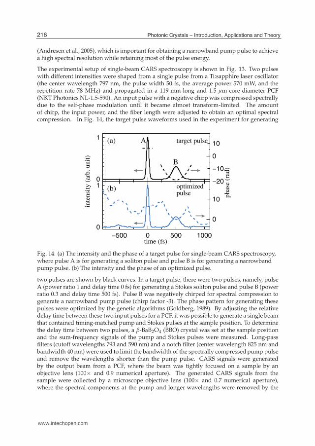
The experimental setup of single-beam CARS spectroscopy is shown in Fig. 13. Two pulseswith different intensities were shaped from a single pulse from a Ti:sapphire laser oscillator(the center wavelength 797 nm, the pulse width 50 fs, the average power 570 mW, and therepetition rate 78 MHz) and propagated in a 119-mm-long and 1.5-µm-core-diameter PCF(NKT Photonics NL-1.5-590). An input pulse with a negative chirp was compressed spectrallydue to the self-phase modulation until it became almost transform-limited. The amountof chirp, the input power, and the fiber length were adjusted to obtain an optimal spectralcompression. In Fig. 14, the target pulse waveforms used in the experiment for generating
−500 0 500 1000
0
1
0
10
0
1
−20
−10
0
10
time (fs)
inte
nsi
ty (
arb
. u
nit
)
target pulse
optimizedpulse p
has
e (r
ad)
A
B
(a)
(b)
Fig. 14. (a) The intensity and the phase of a target pulse for single-beam CARS spectroscopy,where pulse A is for generating a soliton pulse and pulse B is for generating a narrowbandpump pulse. (b) The intensity and the phase of an optimized pulse.
two pulses are shown by black curves. In a target pulse, there were two pulses, namely, pulseA (power ratio 1 and delay time 0 fs) for generating a Stokes soliton pulse and pulse B (powerratio 0.3 and delay time 500 fs). Pulse B was negatively chirped for spectral compression togenerate a narrowband pump pulse (chirp factor -3). The phase pattern for generating thesepulses were optimized by the genetic algorithms (Goldberg, 1989). By adjusting the relativedelay time between these two input pulses for a PCF, it was possible to generate a single beamthat contained timing-matched pump and Stokes pulses at the sample position. To determinethe delay time between two pulses, a β-BaB2O4 (BBO) crystal was set at the sample positionand the sum-frequency signals of the pump and Stokes pulses were measured. Long-passfilters (cutoff wavelengths 793 and 590 nm) and a notch filter (center wavelength 825 nm andbandwidth 40 nm) were used to limit the bandwidth of the spectrally compressed pump pulseand remove the wavelengths shorter than the pump pulse. CARS signals were generatedby the output beam from a PCF, where the beam was tightly focused on a sample by anobjective lens (100× and 0.9 numerical aperture). The generated CARS signals from thesample were collected by a microscope objective lens (100× and 0.7 numerical aperture),where the spectral components at the pump and longer wavelengths were removed by the
216 Photonic Crystals – Introduction, Applications and Theory
www.intechopen.com
Optical Solitons from a Photonic Crystal Fiber and Their Applications 17
760 800 840
0
1
1000 1200
0
1
2600 2800 3000 3200 3400
0
20
40
wavelength (nm)
rela
tiv
e in
ten
sity
(ar
b.
un
it)
laserspectral compression
soliton
~3.5 nm
(a) (b)
wavenumber (cm−1
)
inte
nsi
ty (
arb
. u
nit
)
(c)
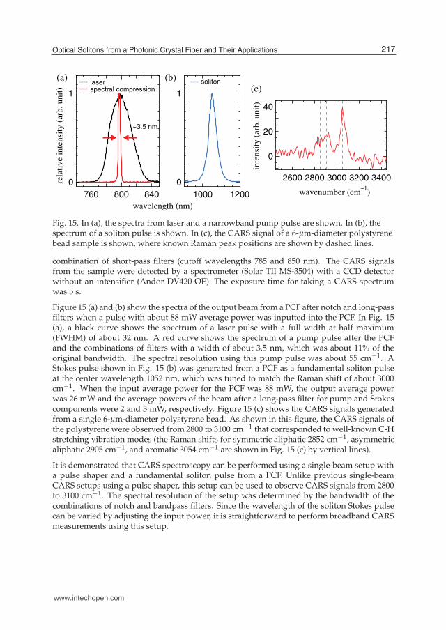
Fig. 15. In (a), the spectra from laser and a narrowband pump pulse are shown. In (b), thespectrum of a soliton pulse is shown. In (c), the CARS signal of a 6-µm-diameter polystyrenebead sample is shown, where known Raman peak positions are shown by dashed lines.
combination of short-pass filters (cutoff wavelengths 785 and 850 nm). The CARS signalsfrom the sample were detected by a spectrometer (Solar TII MS-3504) with a CCD detectorwithout an intensifier (Andor DV420-OE). The exposure time for taking a CARS spectrumwas 5 s.
Figure 15 (a) and (b) show the spectra of the output beam from a PCF after notch and long-passfilters when a pulse with about 88 mW average power was inputted into the PCF. In Fig. 15(a), a black curve shows the spectrum of a laser pulse with a full width at half maximum(FWHM) of about 32 nm. A red curve shows the spectrum of a pump pulse after the PCFand the combinations of filters with a width of about 3.5 nm, which was about 11% of theoriginal bandwidth. The spectral resolution using this pump pulse was about 55 cm−1. AStokes pulse shown in Fig. 15 (b) was generated from a PCF as a fundamental soliton pulseat the center wavelength 1052 nm, which was tuned to match the Raman shift of about 3000cm−1. When the input average power for the PCF was 88 mW, the output average powerwas 26 mW and the average powers of the beam after a long-pass filter for pump and Stokescomponents were 2 and 3 mW, respectively. Figure 15 (c) shows the CARS signals generatedfrom a single 6-µm-diameter polystyrene bead. As shown in this figure, the CARS signals ofthe polystyrene were observed from 2800 to 3100 cm−1 that corresponded to well-known C-Hstretching vibration modes (the Raman shifts for symmetric aliphatic 2852 cm−1, asymmetricaliphatic 2905 cm−1, and aromatic 3054 cm−1 are shown in Fig. 15 (c) by vertical lines).
It is demonstrated that CARS spectroscopy can be performed using a single-beam setup witha pulse shaper and a fundamental soliton pulse from a PCF. Unlike previous single-beamCARS setups using a pulse shaper, this setup can be used to observe CARS signals from 2800to 3100 cm−1. The spectral resolution of the setup was determined by the bandwidth of thecombinations of notch and bandpass filters. Since the wavelength of the soliton Stokes pulsecan be varied by adjusting the input power, it is straightforward to perform broadband CARSmeasurements using this setup.
217Optical Solitons from a Photonic Crystal Fiber and Their Applications
www.intechopen.com
18 Will-be-set-by-IN-TECH
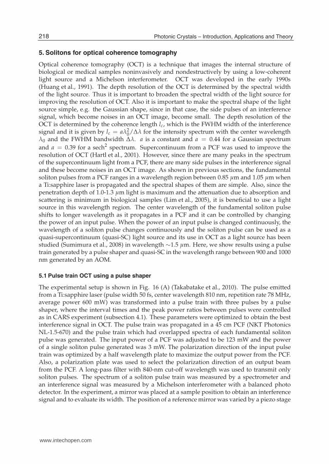
5. Solitons for optical coherence tomography
Optical coherence tomography (OCT) is a technique that images the internal structure ofbiological or medical samples noninvasively and nondestructively by using a low-coherentlight source and a Michelson interferometer. OCT was developed in the early 1990s(Huang et al., 1991). The depth resolution of the OCT is determined by the spectral widthof the light source. Thus it is important to broaden the spectral width of the light source forimproving the resolution of OCT. Also it is important to make the spectral shape of the lightsource simple, e.g. the Gaussian shape, since in that case, the side pulses of an interferencesignal, which become noises in an OCT image, become small. The depth resolution of theOCT is determined by the coherence length lc, which is the FWHM width of the interferencesignal and it is given by lc = aλ2
0/∆λ for the intensity spectrum with the center wavelengthλ0 and the FWHM bandwidth ∆λ. a is a constant and a = 0.44 for a Gaussian spectrum
and a = 0.39 for a sech2 spectrum. Supercontinuum from a PCF was used to improve theresolution of OCT (Hartl et al., 2001). However, since there are many peaks in the spectrumof the supercontinuum light from a PCF, there are many side pulses in the interference signaland these become noises in an OCT image. As shown in previous sections, the fundamentalsoliton pulses from a PCF ranges in a wavelength region between 0.85 µm and 1.05 µm whena Ti:sapphire laser is propagated and the spectral shapes of them are simple. Also, since thepenetration depth of 1.0-1.3 µm light is maximum and the attenuation due to absorption andscattering is minimum in biological samples (Lim et al., 2005), it is beneficial to use a lightsource in this wavelength region. The center wavelength of the fundamental soliton pulseshifts to longer wavelength as it propagates in a PCF and it can be controlled by changingthe power of an input pulse. When the power of an input pulse is changed continuously, thewavelength of a soliton pulse changes continuously and the soliton pulse can be used as aquasi-supercontinuum (quasi-SC) light source and its use in OCT as a light source has beenstudied (Sumimura et al., 2008) in wavelength ∼1.5 µm. Here, we show results using a pulsetrain generated by a pulse shaper and quasi-SC in the wavelength range between 900 and 1000nm generated by an AOM.
5.1 Pulse train OCT using a pulse shaper
The experimental setup is shown in Fig. 16 (A) (Takabatake et al., 2010). The pulse emittedfrom a Ti:sapphire laser (pulse width 50 fs, center wavelength 810 nm, repetition rate 78 MHz,average power 600 mW) was transformed into a pulse train with three pulses by a pulseshaper, where the interval times and the peak power ratios between pulses were controlledas in CARS experiment (subsection 4.1). These parameters were optimized to obtain the bestinterference signal in OCT. The pulse train was propagated in a 45 cm PCF (NKT PhotonicsNL-1.5-670) and the pulse train which had overlapped spectra of each fundamental solitonpulse was generated. The input power of a PCF was adjusted to be 123 mW and the powerof a single soliton pulse generated was 3 mW. The polarization direction of the input pulsetrain was optimized by a half wavelength plate to maximize the output power from the PCF.Also, a polarization plate was used to select the polarization direction of an output beamfrom the PCF. A long-pass filter with 840-nm cut-off wavelength was used to transmit onlysoliton pulses. The spectrum of a soliton pulse train was measured by a spectrometer andan interference signal was measured by a Michelson interferometer with a balanced photodetector. In the experiment, a mirror was placed at a sample position to obtain an interferencesignal and to evaluate its width. The position of a reference mirror was varied by a piezo stage
218 Photonic Crystals – Introduction, Applications and Theory
www.intechopen.com
Optical Solitons from a Photonic Crystal Fiber and Their Applications 19
lowpass filter
computer
waveform generator
piezodriver
oscilloscope
reference mirror
delay
BPD
VND3
VND2
BS2 BS1
OL2 OL1PCFfilter
sample mirrorAOM
VND1
HWP
function generator
AOM driver
Ti:SapphireLaser
VND1HWP
Ti:SapphireLaser
SLMCM
Grating Grating
CM
(A)
(B)
(A)or(B)
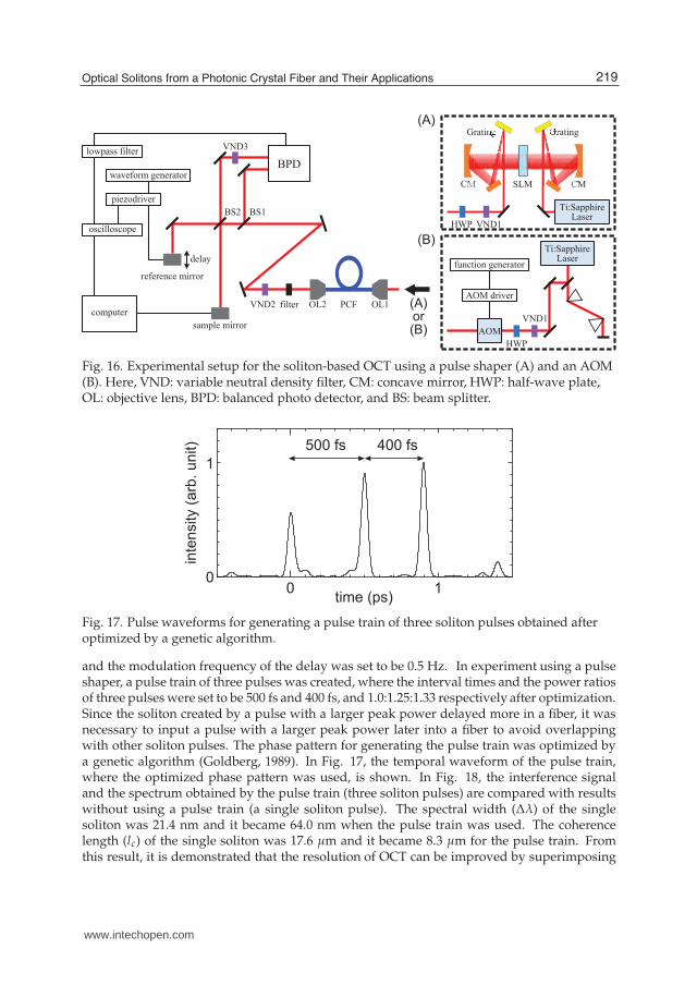
Fig. 16. Experimental setup for the soliton-based OCT using a pulse shaper (A) and an AOM(B). Here, VND: variable neutral density filter, CM: concave mirror, HWP: half-wave plate,OL: objective lens, BPD: balanced photo detector, and BS: beam splitter.
0 10
1
time (ps)
inte
nsity (
arb
. unit) 500 fs 400 fs
Fig. 17. Pulse waveforms for generating a pulse train of three soliton pulses obtained afteroptimized by a genetic algorithm.
and the modulation frequency of the delay was set to be 0.5 Hz. In experiment using a pulseshaper, a pulse train of three pulses was created, where the interval times and the power ratiosof three pulses were set to be 500 fs and 400 fs, and 1.0:1.25:1.33 respectively after optimization.Since the soliton created by a pulse with a larger peak power delayed more in a fiber, it wasnecessary to input a pulse with a larger peak power later into a fiber to avoid overlappingwith other soliton pulses. The phase pattern for generating the pulse train was optimized bya genetic algorithm (Goldberg, 1989). In Fig. 17, the temporal waveform of the pulse train,where the optimized phase pattern was used, is shown. In Fig. 18, the interference signaland the spectrum obtained by the pulse train (three soliton pulses) are compared with resultswithout using a pulse train (a single soliton pulse). The spectral width (∆λ) of the singlesoliton was 21.4 nm and it became 64.0 nm when the pulse train was used. The coherencelength (lc) of the single soliton was 17.6 µm and it became 8.3 µm for the pulse train. Fromthis result, it is demonstrated that the resolution of OCT can be improved by superimposing
219Optical Solitons from a Photonic Crystal Fiber and Their Applications
www.intechopen.com
20 Will-be-set-by-IN-TECH
0
1
-1
0
1
800 900 1000 11000
1
-20 0 20
-1
0
1
wavelength (nm) delay (μm)
inte
nsity (
arb
. u
nit)
Δλ=21.4 nm
λc=938.8 nm
λc=944.0 nm
Δλ=64.0 nm
lc=17.6 μm
lc=8.3 μm
(a) (b)
(d)(c)
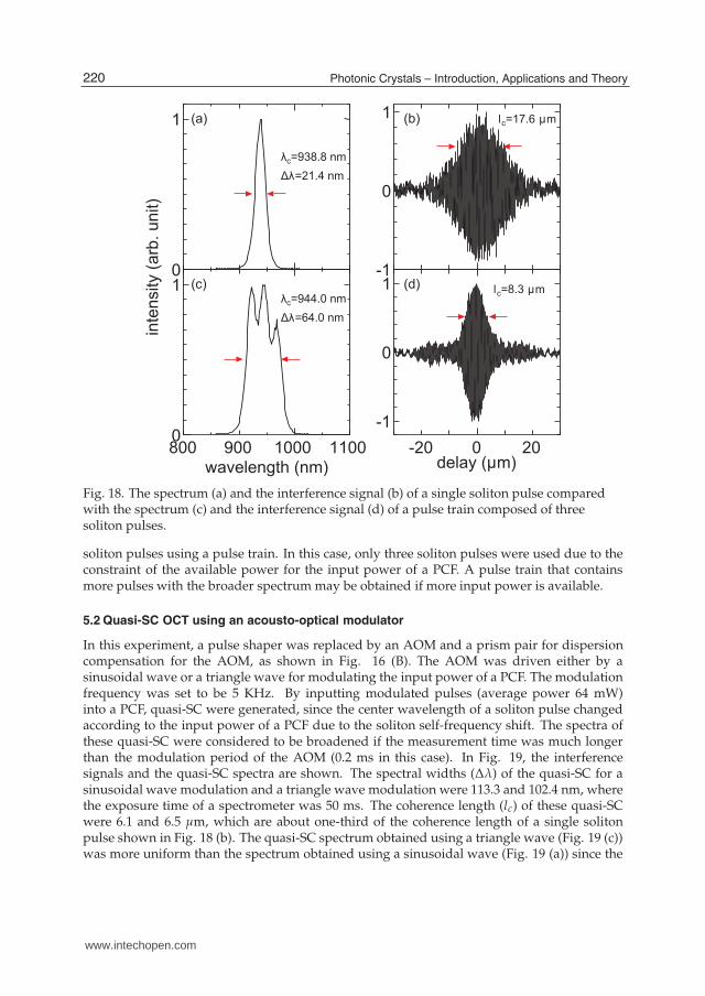
Fig. 18. The spectrum (a) and the interference signal (b) of a single soliton pulse comparedwith the spectrum (c) and the interference signal (d) of a pulse train composed of threesoliton pulses.
soliton pulses using a pulse train. In this case, only three soliton pulses were used due to theconstraint of the available power for the input power of a PCF. A pulse train that containsmore pulses with the broader spectrum may be obtained if more input power is available.
5.2 Quasi-SC OCT using an acousto-optical modulator
In this experiment, a pulse shaper was replaced by an AOM and a prism pair for dispersioncompensation for the AOM, as shown in Fig. 16 (B). The AOM was driven either by asinusoidal wave or a triangle wave for modulating the input power of a PCF. The modulationfrequency was set to be 5 KHz. By inputting modulated pulses (average power 64 mW)into a PCF, quasi-SC were generated, since the center wavelength of a soliton pulse changedaccording to the input power of a PCF due to the soliton self-frequency shift. The spectra ofthese quasi-SC were considered to be broadened if the measurement time was much longerthan the modulation period of the AOM (0.2 ms in this case). In Fig. 19, the interferencesignals and the quasi-SC spectra are shown. The spectral widths (∆λ) of the quasi-SC for asinusoidal wave modulation and a triangle wave modulation were 113.3 and 102.4 nm, wherethe exposure time of a spectrometer was 50 ms. The coherence length (lc) of these quasi-SCwere 6.1 and 6.5 µm, which are about one-third of the coherence length of a single solitonpulse shown in Fig. 18 (b). The quasi-SC spectrum obtained using a triangle wave (Fig. 19 (c))was more uniform than the spectrum obtained using a sinusoidal wave (Fig. 19 (a)) since the
220 Photonic Crystals – Introduction, Applications and Theory
www.intechopen.com

Optical Solitons from a Photonic Crystal Fiber and Their Applications 21
0
1
-1
0
1
900 1000 11000
1
-20 0 20
-1
0
1
wavelength (nm) delay (μm)
inte
nsity (
arb
. u
nit)
Δλ=113.3 nm
λc=954.9 nm
λc=959.3 nm
Δλ=102.4 nm
lc=6.1 μm
lc=6.5 μm
(a) (b)
(d)(c)
Fig. 19. The spectrum (a) and the interference signal (b) of quasi-SC using a sinusoidal wavecompared with the spectrum (c) and the interference signal (d) of quasi-SC using a trianglewave.
variation of the power inputted into a PCF using a triangle wave was more uniform than thatusing a sinusoidal wave. From these results, it is demonstrated that the resolution of OCT canbe improved by using a quasi-SC.
5.3 Comparison between methods using a pulse train and quasi-SC
By comparing the spectrum using a pulse train with three pulses shown in Fig. 18 (c) withthe spectra using an AOM shown in Fig. 19 (a) and (c), we see that the spectral widths ofthe quasi-SC were broader than that of a pulse train and as a result, the coherent lengths ofquasi-SC were smaller than that of a pulse train. Therefore it is advantageous to use quasi-SCto obtain the better resolution in OCT. This is because the throughput of an AOM was higherthan that of a pulse shaper in our experimental setups. Also, it is possible to modify thespectral shape by changing the modulation waveform when using an AOM. However, thespectrum obtained using an AOM shown in Fig. 19 (a) and (c) were not stationary but thecenter wavelength of a soliton in the quasi-SC varied with the modulation frequency of anAOM (5 kHz). On the other hand, the spectrum obtained using a pulse train shown in Fig. 18(c) was obtained by superimposing three soliton pulses and was stationary with the repetitionrate of a laser (78 MHz). The method using quasi-SC may have a problem when the scanningspeed of the OCT setup becomes comparable to the modulation speed of the AOM.
221Optical Solitons from a Photonic Crystal Fiber and Their Applications
www.intechopen.com
22 Will-be-set-by-IN-TECH
6. Conclusion
In this chapter, fundamental soliton pulses generated from a PCF were introduced and theirapplications in CARS spectroscopy and OCT were explained. The wavelength of the solitonpulse changes due to the self-frequency shift and it can be controlled by the power and/or thechirp of a pulse inputted into the PCF. At the same time, the delay time of the soliton pulsechanges, which can be estimated relatively easily. The use of a pulse shaper is very usefulto control the wavelength and the delay time simultaneously and this was used effectivelyin CARS spectroscopy experiment. In CARS experiment, broadband Stokes soliton pulseswere generated and the broadband CARS spectroscopy setups were demonstrated. Also,a single-beam CARS spectroscopy setup was demonstrated using the fundamental solitonpulse. In OCT experiment, broadband pulses in wavelength between 900 and 1000 nm weregenerated using soliton pulses and the improvement of the resolution of the interferencesignals were demonstrated using these pulses.
7. Acknowledgements
We would like to appreciate Yoshihiko Takabatake, Minoru Bunya, Chihiro Satoh and RyohShirakawa who contributed to the work presented in this book chapter. This work wassupported in part by a Grant-in-Aid for Scientific Research (C) from the Japan Society forthe Promotion of Science (JSPS) and a Grant-in-Aid for JSPS Fellows.
8. References
Agrawal, G. P. (2007). Nonlinear Fiber Optics Fourth Ed., Elsevier, Burlington, MA, USA.Andresen, E. R., Thøgersen, J. & Keiding, S. R. (2005). Spectral compression of femtosecond
pulses in photonic crystal fibers, Opt. Lett. Vol. 30 pp. 2025–2027.Blow, K. J. & Wood, D. (1989). Theoretical description of transient stimulated Raman scattering
in optical fibers, IEEE J. Quantum Electron. Vol. 25 pp. 2665–2673.Cheng, J. X. & Xie, X. S. (2004). Coherent anti-Stokes Raman scattering microscopy:
instrumentation, theory, and applications, J. Phys. Chem. B. Vol. 108 pp. 827–840.Dudley, J. M., Genty, G. & Coen, S. (2006). Supercontinuum generation in photonic crystal
fiber, Rev. Mod. Phys. Vol. 78 pp. 1135–1184.Goldberg, D. E. (1989). Genetic Algorithms in Search, Optimization and Machine Learning,
Addison-Wesley, Reading, MA, USA.Gordon, J. P. (1986). Theory of the soliton self-frequency shift, Opt. Lett. Vol. 11, pp. 662–664.Hartl, I., Li, X. D., Chudoba, C., Ghanta, R. K., Ko, T. H., Fujimoto, J. G., Ranka, J. K. &
Windeler, R. S. (2001). Ultrahigh-resolution optical coherence tomography usingcontinuum generation in an air-silica microstructure optical fiber, Opt. Lett. Vol. 26pp. 608–610.
Hasegawa, A. (1992). Optical solitons in fibers: theoretical review, in Taylor, J. R. (ed.), OpticalSolitons – Theory and Experiment , Cambridge Univ. Press, Cambridge, pp.1–29.
Huang, D., Swanson, E. A., Lin, C. P., Schuman, J. S., Stinson, W. G., Chang, W., Hee, M. R.,Flotte, T., Gregory, K., Puliafito, C. A. & Fujimoto, J. G. (1991). Optical coherencetomography, Science Vol. 254 pp. 1178–1181.
Husakou, A. V. & Herrmann, J. (2001). Supercontinuum generation of higher-order solitonsby fission in photonic crystal fibers, Phys. Rev. Lett. Vol. 87 pp. 203901-1–203901-4.
222 Photonic Crystals – Introduction, Applications and Theory
www.intechopen.com
Optical Solitons from a Photonic Crystal Fiber and Their Applications 23
Kano, H. & Hamaguchi, H. (2005). Ultrabroadband (>2500 cm−1) multiplex coherentanti-Stokes Raman scattering microspectroscopy using a supercontinuum generatedfrom a photonic crystal fiber, Appl. Phys. Lett. Vol. 86 pp. 121113-1–121113-3.
Karasawa, N., Nakamura, S., Nakagawa, N., Shibata, M., Morita, R., Shigekawa, H., &Yamashita, M. (2001). Comparison between theory and experiment of nonlinearpropagation for a-few-cycle and ultrabroadband optical pulses in a fused-silica fiber,IEEE J. Quantum Electron. Vol. 37, pp. 398–404.
Karasawa, N., Tada, K., & Ohmori, H. (2007). The comparison between experiment andcalculation of the chirp-controlled Raman self-frequency shift in a photonic crystalfiber, IEEE Photon. Technol. Lett. Vol. 19, pp. 1292–1294.
Kee, T. W. & Cicerone, M. T.. (2004). Simple approach to one-laser, broadband coherentanti-Stokes Raman scattering microscopy Opt. Lett. Vol. 29 pp. 2701–2703.
Lim, H., Jiang, Y., Wang, Y., Huang, Y.-C., Chen, Z. & Wise, F. W. (2005). Ultrahigh-resolutionoptical coherence tomography with a fiber laser source at 1 µm, Opt. Lett. Vol. 30, pp.1171–1173.
Mitschke, F. M. & Mollenauer, F. (1986). Discovery of the soliton self-frequency shift, Opt. Lett.Vol. 11 pp. 659–661.
Morita, R. & Toda, Y. (2005). Field manipulation of ultrabroadband optical pulses, inYamashita, M., Shigekawa, H. & Morita, R. eds., Mono-Cycle Photonics and OpticalScanning Tunneling Microscopy, Springer, Berlin, pp. 251–283.
Müller, M. & Zumbusch, A. (2007). Coherent anti-Stokes Raman scattering microscopy,ChemPhysChem Vol. 8 pp. 2156–2170.
Paulsen, H. N.. Hilligsøe, K. M., Thøgersen, J, Keiding, S. R. & Larsen, J. J. (2003). Coherentanti-Stokes Raman scattering microscopy with a photonic crystal fiber based lightsource, Opt. Lett. Vol. 28 pp. 1123–1125.
Ranka, J., Windeler, R. S. & Stentz, A. J. (2000). Visible continuum generation in air-silicamicrostructure optical fibers with anomalous dispersion at 800 nm, Opt. Lett. Vol. 25,pp. 25–27.
Satsuma, J. & Yajima, N. (1974). Initial value problems of one-dimensional self-modulationof nonlinear waves in dispersive media, Suppl. Prog. Theor. Phys., Japan Vol. 55 pp.284–306.
Schrader, D. (1995). Explicit calculation of N-soliton solutions of the nonlinear Schroedingerequation, IEEE J. Quantum Electron. Vol. 31, pp. 2221–2225.
Sumimura, K., Ohta, T. & Nishizawa, N. (2008). Quasi-super-continuum generation usingultrahigh-speed wavelength-tunable soliton pulses, Opt. Lett. Vol. 33, pp. 2892–2894.
Tada, K. & Karasawa, N. (2008). Broadband coherent anti-Stokes Raman scatteringspectroscopy using pulse-shaper-controlled variable-wavelength soliton pulses froma photonic crystal fiber, Jpn. J. Appl. Phys. Vol. 47 pp. 8825–8828.
Tada, K. & Karasawa, N. (2008). Coherent anti-Stokes Raman scattering microspectroscopyusing a fundamental soliton pulse generated from a photonic crystal fiber, in Tanio,N. & Sasabe, H. eds., Optical Materials and Devices New Stage, PWC Publishing,Chitose, Japan, pp. 215–220.
Tada, K. & Karasawa, N. (2009). Broadband coherent anti-Stokes Raman scatteringspectroscopy using soliton pulse trains from a photonic crystal fiber, Opt. Commun.Vol. 282 pp. 3948–3952.
223Optical Solitons from a Photonic Crystal Fiber and Their Applications
www.intechopen.com

24 Will-be-set-by-IN-TECH
Tada, K. & Karasawa, N. (2010). Broadband coherent anti-Stokes Raman scatteringspectroscopy using a quasi-supercontinuum light source, in Conference on Lasers andElectro-Optics, OSA Technical Digest, paper JTuD72.
Tada, K. & Karasawa, N. (2011). Single-beam coherent anti-Stokes Raman scatteringspectroscopy using both pump and soliton Stokes pulses from a photonic crystalfiber, Appl. Phys. Express Vol. 4 pp. 092701-1–092701-3.
Takabatake, Y., Tada, K. & Karasawa, N. (2010). Optical coherence tomography using a solitonpulse train, in Kawabe, Y. & Kawase, M. eds., Polymer Photonics, and Novel OpticalTechnologies, PWC Publishing, Chitose, Japan, pp. 116–119.
Zolla, F., Renversez, G., Nicolet, A., Kuhlmey, B., Guenneau, S. & Felbacq, D. (2005).Foundations of Photonic Crystal Fibres, Imperial College Press, London.
224 Photonic Crystals – Introduction, Applications and Theory
www.intechopen.com

Photonic Crystals - Introduction, Applications and TheoryEdited by Dr. Alessandro Massaro
ISBN 978-953-51-0431-5Hard cover, 344 pagesPublisher InTechPublished online 30, March, 2012Published in print edition March, 2012
InTech EuropeUniversity Campus STeP Ri Slavka Krautzeka 83/A 51000 Rijeka, Croatia Phone: +385 (51) 770 447 Fax: +385 (51) 686 166www.intechopen.com
InTech ChinaUnit 405, Office Block, Hotel Equatorial Shanghai No.65, Yan An Road (West), Shanghai, 200040, China
Phone: +86-21-62489820 Fax: +86-21-62489821
The first volume of the book concerns the introduction of photonic crystals and applications including designand modeling aspects. Photonic crystals are attractive optical materials for controlling and manipulating theflow of light. In particular, photonic crystals are of great interest for both fundamental and applied research,and the two dimensional ones are beginning to find commercial applications such as optical logic devices,micro electro-mechanical systems (MEMS), sensors. The first commercial products involving two-dimensionally periodic photonic crystals are already available in the form of photonic-crystal fibers, which use amicroscale structure to confine light with radically different characteristics compared to conventional opticalfiber for applications in nonlinear devices and guiding wavelengths. The goal of the first volume is to providean overview about the listed issues.
How to referenceIn order to correctly reference this scholarly work, feel free to copy and paste the following:
Naoki Karasawa and Kazuhiro Tada (2012). Optical Solitons from a Photonic Crystal Fiber and TheirApplications, Photonic Crystals - Introduction, Applications and Theory, Dr. Alessandro Massaro (Ed.), ISBN:978-953-51-0431-5, InTech, Available from: http://www.intechopen.com/books/photonic-crystals-introduction-applications-and-theory/optical-solitons-from-a-photonic-crystal-fiber-and-their-applications

© 2012 The Author(s). Licensee IntechOpen. This is an open access articledistributed under the terms of the Creative Commons Attribution 3.0License, which permits unrestricted use, distribution, and reproduction inany medium, provided the original work is properly cited.