optical fire detection for engine nacelle and auxiliary ... · pdf fileengine nacelle and...
TRANSCRIPT

1
Presented by: Brandon Stanton Kidde Aerospace and DefenseOptics Engineer
Optical Fire Detection for Engine Nacelle and Auxiliary
Power Units

2
The Companies of Kidde Aerospace & Defense
Kidde Dual SpectrumGoleta, CA USAVehicle Protection, Service
Kidde Aerospace & Fenwal Safety SystemsWilson, NC USAFire/Overheat/Smoke/Optical Detection, Controls Extinguishing, System Integration & Service
Kidde Graviner LtdColnbrook, England UKFire Detection, Oxygen, Vehicle Protection, Service
L’Hotellier- S.A.Antony, FranceFire Detection, Extinguishing, ControlsVehicle Protection, Service
Kidde Deugra - KADDusseldorf, GermanyVehicle Protection, Aviation Sales & Service

3
Commercial Aviation Products
Lavatory Fire Protection
Engine/APU FireExtinguishers
Engine FireDetectors Wheelwell Fire
DetectorsCargo Bay Smoke
Detectors Engine/APU FireExtinguishers
Lavatory Smoke
Detector
Cabin Halon 1211 Fire Extinguishers
Cargo Bay Fire Extinguishers
Bleed Air Overheat Detectors
Cabin Water Portable Fire Extinguisher APU Fire
Detectors
Commercial Aviation Products

4
• All Commercial Aircraft Types Require Engine / APU Fire Detection– Exception: some general aviation that do not carry revenue generating
passengers
• History– Continuous Element (Predominant)– Thermal Switches– Optical (High end, Military)
• Increasing Interest in Faster Recognition of Damage Causing Fires– Composites
– Hard to Extinguish– Stealth– Maintainability
– Light Weight– Larger Coverage With Less– Cost
– Response Time
Summary

5
• Thermal– Response Requirements
– 5 sec. to 2000°F flame– Benefits
– Overheat detection– Contamination not an issue
– Limitations– Convective heat transfer– Little false alarm immunity– Hard to remove / maintain– Explosions too fast
• Optical– Response Requirements
– <<5 sec. Depending on the event– Benefits
– Weight reduction / FOV– Cost– Maintainability– Response time
– Explosion detection– Limitations
– Overheat detection– Contamination
Optical vs. Thermal

6
• Flame Radiation– Black body radiation
– Related to flame temperature and amount of particulate matter
– Discrete emissions– UV
– Electronic transitions from atoms, molecules and free radicals
– IR– Rotational/vibrational
transitions from combustion products (CO2 /H2 0 )
Optical Fire Detection – Flame Characteristics
emission spectrum of a small natural gas diffusion flame
0.001
0.01
0.1
1
10
100
0 500 1000 1500 2000 2500 3000 3500 4000 4500 5000
wavelength (nm)
outp
ut (a
.u.)
CO2H2O
H2OH2O
CH4
CO
UV Near-IR Mid-IRVIS
7
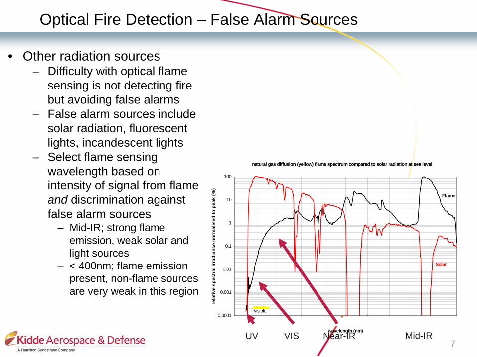
• Other radiation sources– Difficulty with optical flame
sensing is not detecting fire but avoiding false alarms
– False alarm sources include solar radiation, fluorescent lights, incandescent lights
– Select flame sensing wavelength based on intensity of signal from flame and discrimination against false alarm sources
– Mid-IR; strong flame emission, weak solar and light sources
– < 400nm; flame emission present, non-flame sources are very weak in this region
Optical Fire Detection – False Alarm Sources
natural gas diffusion (yellow) flame spectrum compared to solar radiation at sea level
0.0001
0.001
0.01
0.1
1
10
100
0 500 1000 1500 2000 2500 3000 3500 4000 4500 5000
wavelength (nm)
rela
tive
spec
tral
irra
dian
ce n
orm
alis
ed to
pea
k (%
)
visible
Flame
Solar
UV Near-IR Mid-IRVIS

8
• With the development of relatively cheap detectors and interference filters for the middle infrared, infrared flame detection has become common
• These detectors can also be made solar blind
• They are routinely used both in accidental flame detection and in combustion control systems
• They can operate at temperatures up to 125ºC or higher
Infrared Optical Fire Detectors – Background
9
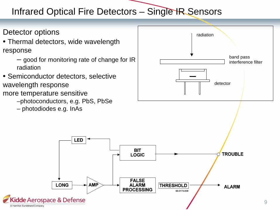
band passinterference filter
detector
radiationDetector options• Thermal detectors, wide wavelength response
– good for monitoring rate of change for IR radiation
• Semiconductor detectors, selective wavelength responsemore temperature sensitive
–photoconductors, e.g. PbS, PbSe– photodiodes e.g. InAs
Infrared Optical Fire Detectors – Single IR Sensors
10
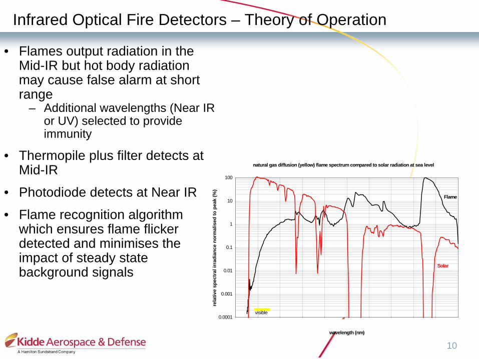
• Flames output radiation in the Mid-IR but hot body radiation may cause false alarm at short range
– Additional wavelengths (Near IR or UV) selected to provide immunity
• Thermopile plus filter detects at Mid-IR
• Photodiode detects at Near IR
• Flame recognition algorithm which ensures flame flicker detected and minimises the impact of steady state background signals
Infrared Optical Fire Detectors – Theory of Operation
natural gas diffusion (yellow) flame spectrum compared to solar radiation at sea level
0.0001
0.001
0.01
0.1
1
10
100
0 500 1000 1500 2000 2500 3000 3500 4000 4500 5000
wavelength (nm)
rela
tive
spec
tral
irra
dian
ce n
orm
alis
ed to
pea
k (%
)
visible
Flame
Solar

11
• Detector “sees” fire (does not need to be placed in the fire)– Field of view -120° solid cone– Response time
– Explosive event– < 5ms response
– Pool / Spray fire event– 2-5 s – Detection requires flame flicker
• False alarm immunity– Improved performance through optical filtering recognises peak emissions
from hydrocarbon flames– “ANDING” technology used to optimise detection performance
• Built in Test provides indication of contamination
Infrared Optical Fire Detectors – Dual IR Sensors

12
• The first flame detectors operated in the visible and near infrared regions of the electromagnetic spectrum but suffered from frequent false alarms
• Solar blind ultraviolet detectors were developed in the 1960s
• They are routinely used both in accidental flame detection and in combustion control systems
• They can operate at temperatures up to 200ºC or higher
Ultraviolet Optical Fire Detectors – Background
natural gas diffusion (yellow) flame spectrum compared to solar radiation at sea level
0.0001
0.001
0.01
0.1
1
10
100
0 500 1000 1500 2000 2500 3000 3500 4000 4500 5000
wavelength (nm)
rela
tive
spec
tral
irra
dian
ce n
orm
alis
ed to
pea
k (%
)
visible
Flame
Solar

13
• UV radiation causes UV sensor to conduct by emission of electrons from cathode
• High voltage field between cathode & anode causes the avalanche effect
• UV tube continues to conduct while voltage is applied
• Counts registered by the control unit; voltage is removed to allow the tube to de-ionise
Ultraviolet Optical Fire Detectors – Theory of Operation
Anode +ve
Cathode -ve
UV photon
Photo-emitted electrongas molecule
+
e-
e-e-
+
e-
e- UV photonion
e-e-

14
Ultraviolet Optical Fire Detectors – Sensor
UV sensor withVoltage potential
Controller turns off voltage
Counter tracks pulses
Threshold
Alarm
• Photocell is also sensitive to high energy cosmic radiation, background count exists; background count employed for BIT
• Count rate in presence of a flame > 40/s
• When any tube channel senses a count in a set time frame, a fire signal is communicated (current system logic)

15
• Smallest: Each detection point requires less volume
• Lightest: Each detection point weighs less
• Highest Reliability: Removes electronics from severe, high- temperature areas. Fiber Optics has ~4X MTBF as electronics in same environment.
• High Operating Temperature 250 – 1000ºC
• Optical Performance (fire response, false-alarm immunity) is competitive
• Economical: Fewer points may be required, comparable or lower cost per point
Fiber Optics Fire Detectors - Background

16
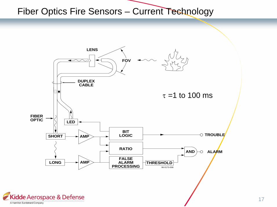
• The Fire Sensors described here are Fiber-Optically coupled:
– A fiber-optically coupled flame detector senses radiation transmitted by an optical fiber.
– The fiber optic acts as a light conduit via total internal reflection
Fiber Optics Fire Detectors - Background
17
LENS
DUPLEX CABLE
FIBEROPTIC
TROUBLE
FOV
LED
BITLOGICAMP
AMP THRESHOLD
AND ALARM
FALSEALARM
PROCESSING
RATIO
LONG
SHORT
96-0173-008
τ
=1 to 100 ms
Fiber Optics Fire Sensors – Current Technology

18
• Obstacles – Overheat coverage– Certification
– Fire hardening (1000ºC)– FAA
– Fear of the unknown– Radiation emitting background (false alarms)– Temperature profile (unknown engine temps)– EMI– Vibration environment
Optical Detection Not The Standard