operator's manualcdnmedia.endeavorsuite.com/images/organizations/63... · read and understand...
TRANSCRIPT
Code No. K7421-7121-7
OPERATOR'S MANUAL
UTILITY VEHICLE
1AYAACQAP0010
AU . B . 8 - 8 . - . AK
RTV-
X900·RTV-X1120D
© KUBOTA Corporation 2013PRINTED IN U.S.A.
READ AND SAVE THIS MANUAL

KUBOTA Corporation is ···Since its inception in 1890, KUBOTA Corporation has grown to rank as one of the major firms in Japan.
To achieve this status, the company has through the years diversified the range of its products and services to a remarkable extent, until today, 19 plants and 16,000 employees produce over 1,000 different items, large and small.
All these products and all the services which accompany them, however, are unified by one central commitment. KUBOTA makes products which, taken on a national scale, are basic necessities. Products which are indispensable, products intended to help individuals and nations fulfill the potential inherent in their environment. For KUBOTA is the Basic Necessities Giant.
This potential includes water supply, food from the soil and from the sea, industrial development, architecture and construction, transportation.
Thousands of people depend on KUBOTA's know-how, technology, experience and customer service. You too can depend on KUBOTA.
Abbreviations Definitions
ABBREVIATION LIST
2 Wheel Drive
4 Wheel Drive
American Petroleum Institute
American Society of Agricultural and Biological Engineers, USA
American Society for Testing and Materials, USA
Deutsches Institut für Normung, GERMANY
Feet Per Minute
Hydrostatic Transmission
Kilometers Per Hour
Miles Per Hour
Meters Per Second
Power Take Off
Right-hand and left-hand sides are determined by facingin the direction of forward travel
Roll-Over Protective Structures
Revolutions Per Minute
Revolutions Per Second
Society of Automotive Engineers, USA
Variable Hydro Transmission
2WD
4WD
API
ASABE
ASTM
DIN
fpm
HST
Km/h
MPH
m/s
PTO
RH/LH
ROPS
rpm
r/s
SAE
VHT
IMPORTANTThe engine in this machine is equipped by the manufacture with a standard spark arrester.It is a violation of California Public Resource Code Section 4442 to use or operate this engine on or near any forest-covered, brush-covered land, or grass- covered land unless the exhaust system is equipped with a working spark arrester meeting state laws. Other states or federal areas may have similar laws.
California Proposition 65
WARNING Engine exhaust, some of its constituents, certain vehicle components and fluids, contain or emit chemicals known to the State of California to cause cancer and birth defects or other reproductive harm.

UNIVERSAL SYMBOLSAs a guide to the operation of your vehicle, various universal symbols have been utilized on the instruments and controls. The symbols are shown below with an indication of their meaning.
Safety Alert Symbol
Seat Belt (2 point type)
Seat Belt (3 point type)
Diesel Fuel
Fuel-Level
Hourmeter/Elapsed Operating Hours
Engine Coolant-Temperature
Brake Fluid
Parking Brake
Battery Charging Condition
Engine Oil-Pressure
VHT Oil-Temperature
Turn Signal/Hazard
Engine-Stop
Engine-Run
Starter Control
Diesel Preheat/Glow Plugs(Low TemperatureStart Aid)
Differential Lock
Differential Lock Hold
Lift Cylinder-Retract
Lift Cylinder-Extend
Lift Cylinder-Float
Steering Wheel-Tilt Control
Hazard Warning Lights
Headlight
Audible Warning Device
Fast
Slow
4-Wheel Drive-On
Lock
Unlock

FOREWORD
3SAFETY FIRST
IMPORTANT :
NOTE :
3 DANGER :
3 WARNING :
3 CAUTION :
Indicates an imminently hazardous situation which, if not avoided, will result in death or serious injury.
Indicates a potentially hazardous situation which, if not avoided, could result in death or serious injury.
Indicates a potentially hazardous situation which, if not avoided, could result in minor or moderate injury.
Indicates that equipment or property damage could result if instructions are not followed.
Gives helpful information.
You are now the proud owner of a KUBOTA Vehicle. This vehicle is a product of KUBOTA quality engineering and manufacturing. It is made of excellent materials and under a rigid quality control system. It will give you long, satisfactory service. To obtain the best use of your vehicle, please read this manual carefully. It will help you become familiar with the operation of the vehicle and contains many helpful hints about vehicle maintenance. This manual contains instructions for minor maintenance, but information about major repairs is outlined in the KUBOTA Work Shop Manual and should be performed only by a KUBOTA Dealer Technician. It is KUBOTA's policy to utilize as quickly as possible every advance in our research. The immediate use of new techniques in the manufacture of products may cause some small parts of this manual to become outdated. KUBOTA distributors and dealers will have the most up-to-date information. Please do not hesitate to consult with them.
This symbol, the industry's ''Safety Alert Symbol'', is used throughout this manual and on labels on the machine itself to warn of the possibility of personal injury. Read these instructions carefully. It is essential that you read the instructions and safety regulations before you attempt to assemble or use this unit.

CONTENTS
SAFE OPERATION ............................................................................................ -1SERVICING OF VEHICLE........................................................................................... 1
SPECIFICATIONS....................................................................................................... 3SPECIFICATION TABLE ......................................................................................... 3TRAVELING SPEEDS ............................................................................................. 4
VEHICLE LIMITATIONS.............................................................................................. 5
INSTRUMENT PANEL AND CONTROLS................................................................... 6LOCATION OF PARTS............................................................................................ 6
PRE-OPERATION CHECK ....................................................................................... 10DAILY CHECK ....................................................................................................... 10
OPERATING THE ENGINE....................................................................................... 11STARTING THE ENGINE...................................................................................... 11
Cold Weather Starting ....................................................................................................13Engine Hand Throttle......................................................................................................13Block Heater ...................................................................................................................13
STOPPING THE ENGINE...................................................................................... 14WARMING UP ....................................................................................................... 14
Warm-Up Transmission Oil in the Low Temperature Range ..........................................14JUMP STARTING .................................................................................................. 14
OPERATING THE VEHICLE..................................................................................... 16OPERATING NEW VEHICLE ................................................................................ 16
Do not Operate the Vehicle at Full Speed for the First 50 Hours ...................................16Changing Lubricating Oil for New Vehicles ....................................................................16
STARTING............................................................................................................. 16Locking and Unlocking the Door.....................................................................................16Seat Belt .........................................................................................................................17Tilt Steering Wheel .........................................................................................................17Seat Slide Lever .............................................................................................................17Head Light Switch...........................................................................................................18Hazard Light Switch........................................................................................................18Turn Signal Light Switch .................................................................................................18Horn Button.....................................................................................................................19Work Light (Front)...........................................................................................................19Work Light (Rear) ...........................................................................................................19Brake Pedal ....................................................................................................................20Range Gear Shift Lever ..................................................................................................204WD Lever......................................................................................................................21Parking Brake Lever .......................................................................................................21Speed Control Pedal.......................................................................................................22
STOPPING............................................................................................................. 22Stopping..........................................................................................................................22
CHECK DURING DRIVING ................................................................................... 22Immediately Stop the Engine if: ......................................................................................22

CONTENTS
Easy Checker(TM)..........................................................................................................22Fuel Gauge.....................................................................................................................23Coolant Temperature Gauge..........................................................................................23Hourmeter and Odometer...............................................................................................24Speedometer ..................................................................................................................24
PARKING............................................................................................................... 25Parking Brake Lever .......................................................................................................25
ACCESSORY......................................................................................................... 2512V Electric Outlet ..........................................................................................................25Utility Box........................................................................................................................25Glove Box (Std.) and Glove Box Cover (if equipped) .....................................................26
OPERATING TECHNIQUES ................................................................................. 26Differential Lock ..............................................................................................................26Directions for Use of Power Steering..............................................................................27Unfamiliar Terrain ...........................................................................................................27Driving in Reverse ..........................................................................................................27Driving in "4WD" .............................................................................................................28Turning the Vehicle.........................................................................................................28Hills .................................................................................................................................29Traversing Hillsides ........................................................................................................29Sliding and Skidding .......................................................................................................29Driving through Water.....................................................................................................30
OPERATING HAND THROTTLE........................................................................... 30STATIONARY HYDRAULIC OUTLET ................................................................... 30
CARGO BED ............................................................................................................. 31CARGO BED.......................................................................................................... 31
General Caution..............................................................................................................31Max. Cargo Load ............................................................................................................31Cargo Bed Tailgate.........................................................................................................33Raising and Lowering the Cargo Bed.............................................................................33Raising and Lowering the Cargo Bed [without hydraulic dump] .....................................35
HYDRAULIC OUTLET............................................................................................... 36HYDRAULIC OUTLET ........................................................................................... 36
Hydraulic Outlet Lever ....................................................................................................36Hydraulic Outlet Valve Coupler Connecting and Disconnecting.....................................37
TIRES AND WHEELS ............................................................................................... 38TIRES..................................................................................................................... 38
Inflation Pressure............................................................................................................38Tire Type and Use ..........................................................................................................38
WHEELS................................................................................................................ 39SHOCK ABSORBERS........................................................................................... 39
Shock Absorber Spring Adjustment................................................................................39
TOWING AND TRANSPORTING.............................................................................. 40TOWING AND TRANSPORTING .......................................................................... 40
Rear Trailer Hitch............................................................................................................40Front Trailer Hitch ...........................................................................................................40Winch Mount Bracket......................................................................................................41Transport the Vehicle Safely...........................................................................................41

CONTENTS
MAINTENANCE......................................................................................................... 42SERVICE INTERVALS .......................................................................................... 42LUBRICANTS, FUEL AND COOLANT .................................................................. 45
PERIODIC SERVICE................................................................................................. 49HOW TO OPEN THE HOOD AND TILT THE SEAT.............................................. 49
Hood ...............................................................................................................................49Seat ................................................................................................................................49
HOW TO RAISE THE CARGO BED...................................................................... 50Raising and Lowering the Cargo Bed [if equipped with hydraulic dump]........................50Raising and Lowering the Cargo Bed [without hydraulic dump] .....................................50
JACK-UP POINT.................................................................................................... 50Front End........................................................................................................................50Rear End.........................................................................................................................51
DAILY CHECK ....................................................................................................... 51Walk Around Inspection..................................................................................................51Checking around Engine ................................................................................................51Checking and Refueling..................................................................................................52Checking Engine Oil Level..............................................................................................52Checking Transmission Fluid Level ................................................................................53Checking Hydraulic Oil Tank Level.................................................................................53Checking Coolant Level..................................................................................................54Cleaning Radiator Screen...............................................................................................54Cleaning Oil Cooler Net ..................................................................................................55Checking Brake Fluid Level ............................................................................................55Checking Brake Pedal ....................................................................................................56Checking Parking Brake .................................................................................................56Checking Easy Checker(TM)..........................................................................................56Checking Head Light, Turn Signal Light (if equipped) etc. .............................................56Checking Seat Belt and ROPS.......................................................................................56Checking Joint Boot........................................................................................................57Checking Tire Inflation Pressure.....................................................................................58Checking Backup Beeper ...............................................................................................58
EVERY 50 HOURS................................................................................................ 59Greasing .........................................................................................................................59Checking Engine Start System.......................................................................................60
EVERY 100 HOURS.............................................................................................. 61Checking VHT Neutral Spring.........................................................................................61Checking VHT Pressure Release...................................................................................61Checking Wheel Fastener Torque..................................................................................62Cleaning Air Cleaner Primary Element ...........................................................................62Adjusting Alternator Belt Tension ...................................................................................63Checking Fuel Filter........................................................................................................63Checking Battery Condition ............................................................................................64Adjusting Toe-in..............................................................................................................66Cleaning Muffler..............................................................................................................67
EVERY 200 HOURS.............................................................................................. 68Adjusting Parking Brake .................................................................................................68Replacing Engine Oil Filter .............................................................................................69Changing Engine Oil.......................................................................................................69Replacing Transmission Oil Filter [VHT].........................................................................70Replacing Transmission Oil Filter [SUCTION]................................................................71

CONTENTS
Changing Hydraulic Tank Oil ..........................................................................................71Checking Brake Pedal ....................................................................................................72Checking Front Brake Case............................................................................................73Checking Brake Light Switch ..........................................................................................73
EVERY 300 HOURS.............................................................................................. 74Checking Tire..................................................................................................................74
EVERY 400 HOURS.............................................................................................. 74Changing Front Knuckle Case Oil ..................................................................................74Changing Transmission Fluid .........................................................................................75Changing Front Axle Case Oil ........................................................................................76Replacing Fuel Filter.......................................................................................................76
EVERY 800 HOURS.............................................................................................. 76Adjusting Engine Valve Clearance .................................................................................76
EVERY 1000 HOURS or EVERY 1 YEAR............................................................. 76Replacing Air Cleaner Primary Element and Secondary Element..................................76
EVERY 1500 HOURS............................................................................................ 76Checking Fuel Injection Nozzle Injection Pressure.........................................................76
EVERY 2000 HOURS or EVERY 2 YEARS .......................................................... 76Flushing Cooling System and Changing Coolant ...........................................................76Anti-Freeze .....................................................................................................................77
EVERY 3000 HOURS............................................................................................ 78Checking Injection Pump................................................................................................78
EVERY 1 YEAR ..................................................................................................... 78Checking Fuel Lines .......................................................................................................78Checking Hydraulic Oil Line............................................................................................78Checking Radiator Hose, Pipe and Clamp .....................................................................79Checking Intake Air Line.................................................................................................80Checking Engine Breather Hose ....................................................................................81Checking Brake Hose and Pipe......................................................................................81
EVERY 2 YEARS................................................................................................... 82Changing Brake Fluid .....................................................................................................82
EVERY 4 YEARS................................................................................................... 82Replacing Hydraulic Oil Line...........................................................................................82Replacing Radiator Hose (Water pipes) .........................................................................82Replacing Fuel Hose ......................................................................................................82Replacing Engine Breather Hose ...................................................................................82Replacing Brake Master Cylinder (Inner Parts) ..............................................................82Replacing Front Brake Seal............................................................................................82Replacing Rear Brake Cylinder Seal ..............................................................................82Replacing Intake Air Line................................................................................................82Replacing Brake Hose and Pipe.....................................................................................82
SERVICE AS REQUIRED...................................................................................... 83Bleeding Fuel System.....................................................................................................83Cleaning around Engine .................................................................................................83Replacing Fuse...............................................................................................................83Replacing Slow-Blow Fuses ...........................................................................................85Replacing Light Bulb.......................................................................................................85Checking Hydraulic Tank Suction Strainer .....................................................................85
STORAGE ................................................................................................................. 86VEHICLE STORAGE ............................................................................................. 86REMOVING THE VEHICLE FROM STORAGE..................................................... 86

CONTENTS
TROUBLESHOOTING............................................................................................... 87ENGINE TROUBLESHOOTING ............................................................................ 87BATTERY TROUBLESHOOTING ......................................................................... 88MACHINE TROUBLESHOOTING ......................................................................... 89
OPTIONS................................................................................................................... 90
INDEX........................................................................................................................ 91


-1SAFE OPERATION
SAFE OPERATION
Careful operation is your best insurance against anaccident.Read and understand this Operator's Manual carefullybefore operating the vehicle.All operators, no matter how much experience they mayhave, should read this and other related manuals beforeoperating the vehicle or any implement attached to it. It isthe owner's obligation to instruct all operators in safeoperation.1. Know your equipment and its limitations. Read thisentire manual before attempting to start and operatethe vehicle.
2. Pay special attention to the Danger, Warning andCaution labels on the vehicle.
3. Do not remove Roll-Over Protective Structures(ROPS) for any application and fasten seat belts at alltimes. This combination will reduce the risk of seriousinjury or death, should the vehicle be upset.If the ROPS is loosened or removed for any reason,make sure that all parts are reinstalled correctly beforeoperating the vehicle.Never modify or repair a ROPS because welding,bending, drilling, grinding, or cutting may weaken thestructure.If any structural member of the ROPS is damaged,replace the entire structure at your local KUBOTADealer.
4. Always use the seat belts. Check the seat beltsregularly and replace if frayed or damaged.
5. Do not operate the vehicle or any implement attachedto it while under the influence of alcohol, medication,controlled substances or while fatigued.
6. Carefully check the vicinity before operating thevehicle or any implement attached to it. Check foroverhead clearance which may interfere with the CABor ROPS. Do not allow any bystanders around or nearthe vehicle during operation.
7. Never allow anyone under age 16 or without a validdriver's license to operate this vehicle.
8. Before allowing other people to use your vehicle,explain how to operate and have them read thismanual before operation.
9. Never wear loose, torn, or bulky clothing around thevehicle. It may catch on moving parts or controls,leading to the risk of an accident. Use additional safetyitems, e.g. helmet, safety boots or shoes, eye andhearing protection, gloves, etc., as appropriate orrequired.
10.This vehicle is for off road use only.KUBOTA does not recommend operating on publicroads.
11. In addition to the driver, only 1 passenger should ridein the vehicle.Minimum age for passenger is 5 years old.
12.Keep all shields in place and stay away from allmoving parts.
13.Check brakes, speed control pedal, and othermechanical parts for improper adjustment and wear.Replace worn or damaged parts promptly. Check thetightness of all nuts and bolts regularly. (For furtherdetails, see "MAINTENANCE" section.)
14.Keep your vehicle clean. Dirt, grease, and trash buildup may contribute to fires and lead to personal injury.
15.Use only implements meeting the specifications listedunder "VEHICLE LIMITATIONS" in this manual orimplements approved by KUBOTA.
16.The maximum cargo capacity of this vehicle is 500 kg(1100 lbs.). Reduce cargo capacity to match operatingconditions.Avoid top-heavy loading and ensure that the center-of-gravity remains as low as possible.Do not carry anything which sticks outside the cargobed.
17.Do not modify the vehicle. Unauthorized modificationmay affect the function of the vehicle, which may resultin personal injury.
18.Do not carry small children on lap.
1. BEFORE OPERATING THE VEHICLE
(1) ROPS(2) Seat belt

SAFE OPERATION-2
Operator safety is a priority. Safe operation, specificallywith respect to overturning hazards, entails understandingthe equipment and environmental conditions at the time ofuse. Some prohibited uses which can affect overturninghazards include traveling and turning with implementsand loads carried too high etc. This manual sets forthsome of the obvious risks, but the list is not, and cannotbe, exhaustive. It is the operator's responsibility to be alertfor any equipment or environmental condition that couldcompromise safe operation.
C Starting1. Always sit in the operator's seat when starting engine
or operating levers or controls.2. Before starting the engine, make sure that all levers
are in their neutral positions, that the parking brake isengaged, and that the hydraulic outlet (if equipped) isOFF. And make sure the engine hand throttle (ifequipped) is in its idle engine speed position.
3. Do not start engine by shorting across starterterminals or bypassing the safety start switch. Thevehicle may start in gear and move if normal startingcircuitry is bypassed.
4. Be sure that the operator (and passenger) are properlypositioned and seat belts are appropriately fastened.
5. Do not operate or idle engine in a non-ventilated area.Carbon monoxide gas is colorless, odorless, anddeadly.
C Operating1. Always wear the seat belt when operating the unit.2. Do not wear headphones while operating.3. Pull only from the trailer hitch (if equipped). Never hitch
to any other point except trailer hitch; sucharrangements will increase the risk of serious personalinjury or death due to a vehicle upset.
4. Keep all shields and guards in place. Replace any thatare missing or damaged.
5. Avoid sudden starts. To avoid rollovers, slow downwhen turning, on uneven ground, and before stopping.While increasing engine speed with the engine handthrottle (if equipped), operate the speed control pedalwith great care to avoid sudden starts.
6. The vehicle cannot turn with the differential locked andattempting to do so could be dangerous.
7. Do not operate near ditches, holes, embankments, orother ground surface features which may collapseunder the vehicle's weight. The risk of vehicle upset iseven higher when the ground is loose or wet.
8. Watch where you are going at all times. Watch for andavoid obstacles. Be alert at row ends, near trees, andother obstructions.
9. When working in groups, always let the others knowwhat you are going to do before you do it.
10.Never try to get on or off a moving vehicle.11.Do not stand between vehicle and trailer unless
parking brake is applied.
C Safety for childrenTragedy can occur if the operator is not alert to thepresence of children. Children generally are attracted tovehicles and the work they do.1. Never assume that children will remain where you last
saw them.2. Keep children out of the work area and under the
watchful eye of another responsible adult.3. Be alert and shut your vehicle down if children enter
the work area.4. Never carry children in the cargo bed. There is no safe
place for them to ride. No person under the age of 5may ride as a passenger in this vehicle. A passengerunder 5 years of age requires special restraints whichare not available with this vehicle.
5. Never allow children to operate the vehicle even underadult supervision.
6. Never allow children to play on the vehicle or on theimplement.
7. Use extra caution when backing up. Look behind anddown to make sure area is clear before moving.
8. Whenever possible, park your vehicle on a firm, flatand level surface. If this is not possible, park it acrossthe slope. Set the parking brake(s), lower theimplements to the ground, remove the key from theignition and lock the door (if equipped) and chock thewheels.
C Operating on slopesSlopes are a major factor related to loss-of-control and tip-over accidents, which can result in severe injury or death.All slopes require extra caution.1. Travel straight up or down hill.2. Reduce load when operating on hilly or over rough
terrain.3. Keep front wheels straight at crest of hill or going over
bumps.
2. OPERATING THE VEHICLE
(1) Trailer hitch (if equipped)

-3SAFE OPERATION
4. Do not stop or start suddenly when going uphill ordownhill. Be especially cautious when changingdirection on slopes.
5. If vehicle stops or loses power going up a hill, lockparking brake to hold vehicle on slope. Maintaindirection of travel and release brake slowly. Backstraight downhill while maintaining control. Do not turnvehicle sideways. Vehicle is more stable in a straightforward or rearward position.
6. When riding on soft terrain, turn front wheels slightlyuphill to keep vehicle on a straight line across the hill.
7. If the vehicle begins to tip, turn front wheels downhill togain control before proceeding.(1) To avoid upsets, always back up steep slopes. If
you cannot back up the slope or if you feel uneasyon it, do not operate on it. Stay off slopes toosteep for safe operation.
(2) Driving forward out of a ditch, mired condition orup a steep slope increases the risk of a vehicle tobe upset backward. Always back out of thesesituations. Extra caution is required with 4-wheeldrive mode because the increased traction cangive the operator false confidence in the vehicle'sability to climb slopes.
(3) Keep all movement on slopes slow and gradual.Do not make sudden changes in speed, directionor apply brake and make sudden motions of thesteering wheel.
(4) Special attention should be made to the weightand location of implements and loads as such willaffect the stability of the vehicle.
C Operation in inclement conditions1. Only operate during daylight or with good artificial
light.2. Operate vehicle in an open, unobstructed area.3. Use helmet and/or protective gear as appropriate or
required for the operating conditions.4. Reduce speed according to trail, terrain and visibility
conditions.5. Never drive exceeding the limit of visibility. Slow down
near crest of hill until getting a clear view of the otherside.
6. Stay alert for holes, rocks and other hidden hazards inthe terrain.
7. Never cross any body of water where depth may beunknown to the operator (Deep water is consideredanything in excess the bottom edge of the axle cap).Choose a course within the waterway where bothbanks have a gradual incline. Cross at a point knownto be safe.
C Driving the vehicle at high speeds1. Check the front wheel engagement. The braking
characteristics are different between 2 and 4 wheeldrive. Be aware of the difference and use carefully.
2. Always slow the vehicle down before turning. Turningat high speed may tip the vehicle over.
3. Turn the headlights on.
4. Drive at speeds that allow you to maintain control at alltimes.
5. Do not apply the differential lock while traveling at highspeeds. The vehicle may run out of control.
6. Avoid sudden motions of the steering wheel as theycan lead to a dangerous loss of stability. The risk isespecially great when the vehicle is traveling at highspeeds.
C Other miscellaneous1. Clean platform if dirty and remove any debris from
around foot controls.2. Always keep both hands on the steering wheel.3. Always keep arms and legs inside the operating
compartment.4. Never operate the vehicle while standing.5. Do not tow a cart with any riders on it.6. Never attempt wheelies, jumps or other stunts.
1. No riders in cargo bed or anywhere else.2. Do not overload vehicle. Securely anchor all loads.3. Be sure load is evenly distributed.4. Reduce cargo capacity when operating on rough or
hilly terrain.5. Balance loads evenly and secure them. Braking could
shift the load and affect vehicle stability.6. Never operate vehicle with the cargo bed raised.7. Operate cargo bed dump with vehicle stationary and
parking brake locked. Do not dump while moving.8. Operate hydraulic dump (if equipped) on level ground
only.9. Operate dump from operator's seat only.10.Do not place hands or body under the cargo bed when
lowering bed.
1. Before installing or using hydraulic outlet drivenequipment, read the manufacturer's manual andreview the safety labels attached to the equipment.
2. Wait until all moving components have completelystopped before getting off the vehicle, connecting,disconnecting, adjusting, cleaning, or servicing anyhydraulically driven equipment.
3. When operating stationary hydraulically drivenequipment, always apply the vehicle parking brakeand place chocks behind and in front of the rearwheels. Stay clear of all rotating parts. Never step overrotating parts.
3. HAULING LOADS IN THE CARGO BED
4. OPERATING HYDRAULIC OUTLET DRIVEN EQUIPMENT (IF EQUIPPED)

SAFE OPERATION-4
1. Make sure the HYDRAULIC OUTLET is off (ifequipped), lower all implements to the ground, placeall control levers in their neutral positions, set theparking brake, stop the engine, and remove the key.
2. Make sure that the vehicle has come to a completestop before dismounting.
3. Avoid parking on steep slopes, if at all possible park ona firm and level surface; if not, park across a slope withchock the wheels and always with attachment on theground.Failure to comply with this warning may allow thevehicle to move and could cause injury or death.
1. Disengage power to attachment(s) when transportingor not in use.
2. Do not tow this vehicle. Use a suitable truck or trailerwhen transporting on public roads.
3. Use extra care when loading or unloading the vehicleinto a trailer or truck.
Before servicing the vehicle, park it on a firm, flat and levelsurface, set the parking brake, lower all implements to theground, place the range gear shift lever in neutral, stop theengine and remove the key.1. Allow the vehicle time to cool off before working on or
near the engine, muffler, radiator, etc.2. Always stop the engine before refueling. Avoid spills
and overfilling.3. Do not smoke when working around battery or when
refueling. Keep all sparks and flames away frombattery and fuel tank. The battery presents anexplosive hazard, because it gives off hydrogen andoxygen especially when recharging.
4. Before "jump starting" a dead battery, read and followall of the instructions. (See "JUMP STARTING" in"OPERATING THE ENGINE" section.)
5. Keep first aid kit and fire extinguisher handy at alltimes.
6. Disconnect the battery's ground cable before workingon or near electric components.
7. To avoid the possibility of battery explosion, do not useor charge the refillable type battery if the fluid level isbelow the LOWER (lower limit level) mark. Check thefluid level regularly and add distilled water as requiredso that the fluid level is between the UPPER andLOWER marks.
8. To avoid sparks from an accidental short circuit,always disconnect the battery's ground cable (-) firstand reconnect it last.
9. Do not remove radiator cap while coolant is hot. Whencool, slowly rotate cap to the first stop and allowsufficient time for excess pressure to escape beforeremoving the cap completely. This vehicle has acoolant recovery tank, add coolant or water to the tank,not the radiator. (See "Checking Coolant Level" in"DAILY CHECK" in "PERIODIC SERVICE" section.)
(1) Hydraulic outlet (if equipped)
5. PARKING THE VEHICLE
(1) Parking brake lever
6. TRANSPORTING
7. SERVICING THE VEHICLE
(1) Battery

-5SAFE OPERATION
10.Do not attempt to mount a tire on a rim. This should bedone by a qualified person with the proper equipment.
11.Always maintain the correct tire pressure. Do notinflate tires above the recommended pressure shownin the operator's manual.
12.Securely support the vehicle when changing wheels.13.Make sure that wheel bolts and nuts have been
tightened to the specified torque.14.Do not work under any hydraulically supported
devices. They can settle, suddenly leak down, or beaccidentally lowered. If it is necessary to work underthe vehicle or any vehicle elements for servicing oradjustment, securely support them with stands orsuitable blocking beforehand.
15.Escaping hydraulic fluid under pressure has sufficientforce to penetrate skin causing serious personal injury.Before disconnecting hydraulic lines, be sure torelease all residual pressure. Before applyingpressure to the hydraulic system, make sure that allconnections are tight and that all lines, pipes, andhoses are free of damage."High pressure fluid - Injection into body" hazardwarning.
16.Fluid escaping from pinholes may be invisible. Do notuse hands to search for suspected leaks; use a pieceof cardboard or wood. Use of safety goggles or othereye protection is also highly recommended. If injuredby escaping fluid, see a medical doctor at once. Thisfluid will produce gangrene or severe allergic reaction.
17.Waste products such as used oil, fuel, hydraulic fluid,and batteries, can harm the environment, people, petsand wildlife. Please dispose properly.See your local Recycling Center or KUBOTA Dealer tolearn how to recycle or get rid of waste products.
(1) Cardboard(2) Hydraulic line(3) Magnifying glass
SAFE OPERATION-6
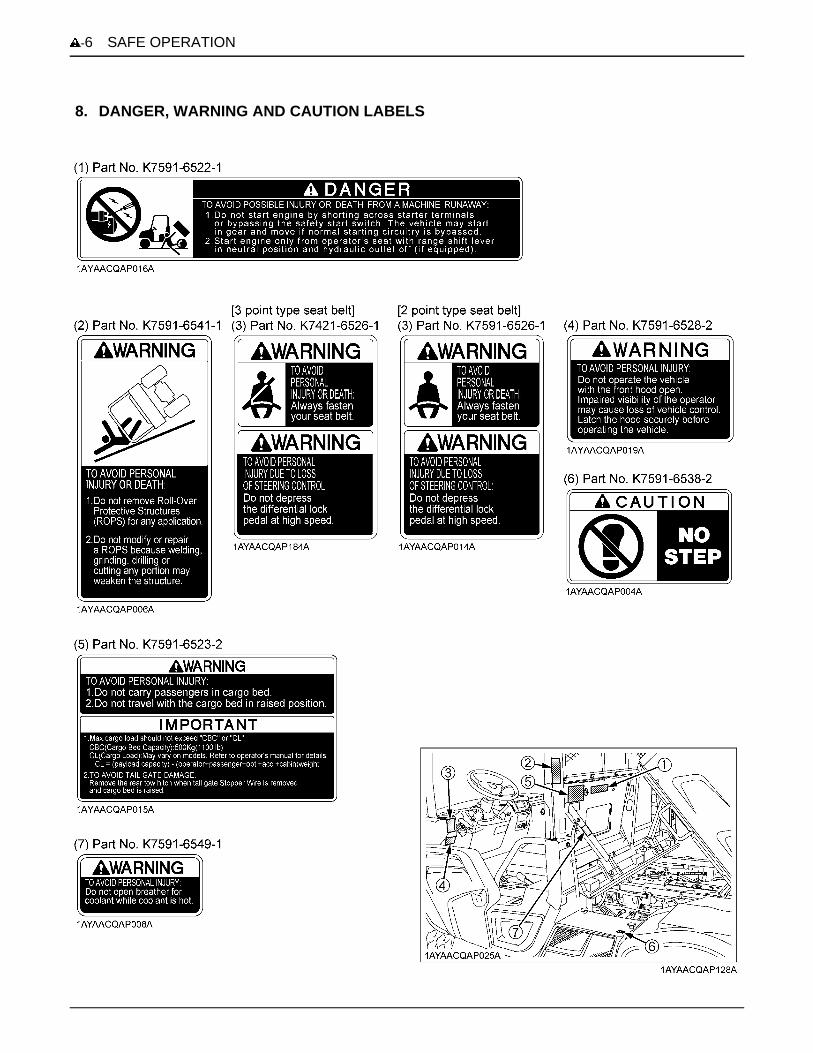
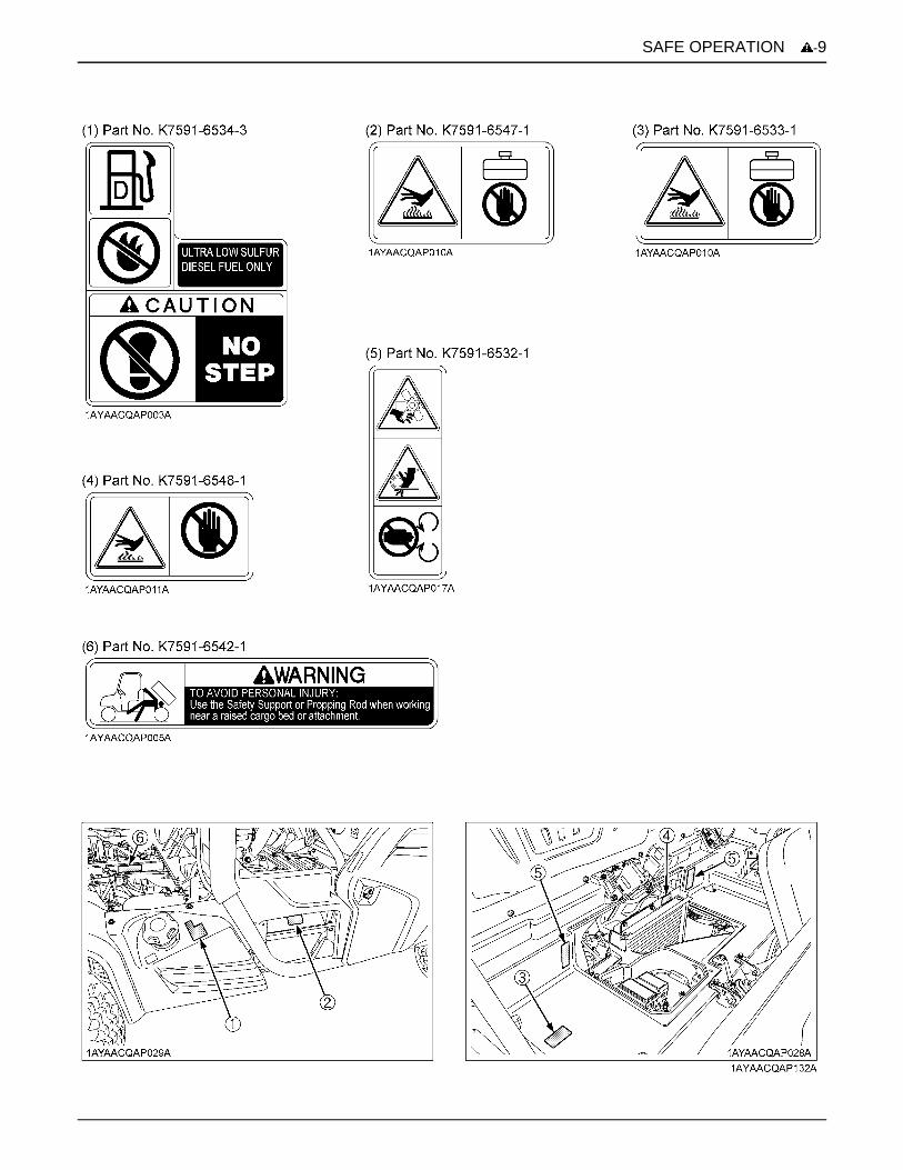
8. DANGER, WARNING AND CAUTION LABELS

-7SAFE OPERATION

SAFE OPERATION-8
-9SAFE OPERATION

SAFE OPERATION-10

-11SAFE OPERATION
1. Keep danger, warning and caution labels clean and free from obstructing material.2. Clean danger, warning and caution labels with soap and water, dry with a soft cloth.3. Replace damaged or missing danger, warning and caution labels with new labels from your local KUBOTA Dealer.4. If a component with danger, warning and caution label(s) affixed is replaced with new part, make sure new label(s)
is(are) attached in the same location(s) as the replaced component.5. Mount new danger, warning and caution labels by applying on a clean dry surface and pressing any bubbles to outside
edge.
9. CARE OF DANGER, WARNING AND CAUTION LABELS


1SERVICING OF VEHICLE
SERVICING OF VEHICLE
Your dealer is interested in your new vehicle and has thedesire to help you get the most value from it. After readingthis manual thoroughly, you will find that you can do someof the regular maintenance by yourself.However, when in need of parts or major service, be sureto see your KUBOTA Dealer.For service, contact the KUBOTA Dealership from whichyou purchased your vehicle or your local KUBOTADealer.When in need of parts, be prepared to give your dealer theserial number of the vehicle, engine, transmission andROPS.Locate the serial numbers now and record them in thespace provided.C WarrantyThis vehicle is warranted under the Kubota LimitedExpress warranty a copy of which may be obtained fromyour selling dealer. No warranty shall, however, apply ifthe vehicle has not been handled according to theinstruction given in the Operator's Manual even it is withinthe warranty period.
C Scrapping the vehicle and its procedureTo put the vehicle out of service, correctly follow the localrules and regulations of the country or territory where youscrap it. If you have questions, consult your localKUBOTA Dealer.
Type Serial No.
Vehicle
Engine
Transmission
ROPS
Product Identification Number
Date of Purchase
Name of Dealer(To be filled in by purchaser)
(1) Vehicle identification plate(2) Product identification number(3) ROPS serial number

SERVICING OF VEHICLE2
[RTV-X900]
[RTV-X1120D]
(1) Engine serial number(2) Transmission assy serial number

3SPECIFICATIONS
SPECIFICATIONS
SPECIFICATION TABLEModelRTV-X900 RTV-X1120D
GeneralPurpose
Worksite/Orange
Worksite/Camo
Worksite/Orange
Worksite/Camo
Engine
Make D902 D1105
Type 3 cylinders, 4-cycle, diesel, OHV
Displacement L (cu. in.) 0.898 (54.8) 1.123 (68.53)
Horsepower kW (HP) 16.1 (21.6) 18.5 (24.8)
Rated revolution rpm 3200 3000
Low idling revolution rpm 1300 to 1400 1350 to 1450
Fuel Capacity L (U.S.gals) 30 (7.9)
Transmission Continuously variable hydro transmission (VHT)
Wheels, Drive system 4, Rear 2WD or 4WD
Differential lock Standard; foot operated with mechanical holder
Gear selection Hi-Low range forward, neutral, reverse
BrakesFront / Rear Wet disk brake
Parking brake Rear wheel, hand lever
Steering Hydrostatic power
SuspensionFront
Independent, Dual A-Arm typeRear
Dimensions
Length mm (in.) 3055 (120.3) 3110 (122.5)
Width mm (in.) 1605 (63.2)
Height, overall mm (in.) 2020 (79.5)
Front tread centers mm (in.) 1240 (48.8) HDWS, ATV1290 (50.8) TurfRear tread centers mm (in.)
Wheelbase mm (in.) 2045 (80.5)
Ground clearance
front axle mm (in.) 266 (10.5)
rear axle mm (in.) 263 (10.4)
Turning diameter m (ft) 8.0 (26.2)
Max. Rolling weight(Towing capacity) kg (lbs.) Rear: 590 (1300), Front: 295 (650)
Payload capacity kg (lbs.) 755 (1664) 725 (1598) 685 (1510)
Weight kg (lbs.) 865 (1907) 895 (1973) 935 (2061)
Gross Vehicle WeightRating (GVWR) kg (lbs.) 1620 (3571)

4 SPECIFICATIONS
A The company reserves the right to change the specifications without notice.A The values in "Ground clearance" and "Weight" are those of the machine equipped with the tires in the table above.
TRAVELING SPEEDS
Cargo bed
Width mm (in.) 1465 (57.7)
Length mm (in.) 1030 (40.5)
Depth mm (in.) 285 (11.2)
Volume m (cu.ft.) 0.43 (15.2)
Bed height(unloaded) mm (in.) 887 (34.9)
Cargo bed capacity kg (lbs.) 500 (1102)
Sound level, operator ear db (A) 85 84
Tires
Front25x10-12 ATV, 6PLY
25x10-12 HDWS, 6PLY25x12-12 Turf, 4PLY
25x10-12 ATV, 6PLY25x10-12 HDWS, 6PLY
Rear25x10-12 ATV, 6PLY
25x10-12 HDWS, 6PLY25x12-12 Turf, 4PLY
25x10-12 ATV, 6PLY25x10-12 HDWS, 6PLY
Tilt steering wheel - Std.
Seat belt 2 point type 3 point type
Front deluxe guard - Std. Std. - -
Front deluxe guard with light guard - - - Std. Std.
Body color Orange Orange Camo Orange Camo
Bed lift - Std. Std. Std. Std.
Speedometer Std. Std. Std. Std. Std.
Door - - - Std. Std.
Seat slide - Std. Std. Std. Std.
Range gear shift lever
Gear positionTraveling speeds
RTV-X900 RTV-X1120D
Low km/h (mph) 24 (15) 25 (16)
High km/h (mph) 40 (25) 46 (29)
Reverse km/h (mph) 27 (17) 35 (22)
ModelRTV-X900 RTV-X1120D
GeneralPurpose
Worksite/Orange
Worksite/Camo
Worksite/Orange
Worksite/Camo

5VEHICLE LIMITATIONS
VEHICLE LIMITATIONS
The KUBOTA Vehicle has been thoroughly tested for proper performance with implements sold or approved by KUBOTA.Use with implements which are not sold or approved by KUBOTA and which exceed the maximum specifications listedbelow, or which are otherwise unfit for use with the KUBOTA Vehicle may result in malfunctions or failures of the vehicle,damage to other property and injury to the operator or others. [Any malfunctions or failures of the vehicle resulting from usewith improper implements are not covered by the warranty][Payload Capacity (PC)]
A Above mentioned specifications are based on level ground condition.
Cargo bed
Max. Cargo loading weight (W1) should not exceed "CBC" and "PCL".PCL (Permissible Cargo load) is determined by the following calculus equation.
PCL = PC - (operator + passenger + opt. + acc. + cabin) weight
CBC (Cargo bed capacity): 500 kg (1100 lbs.)PC: Payload Capacityopt.: optionacc.: accessorycabin: 125 kg (275 lbs.)
Rear trailer hitch Max. rolling weight (W2): 590 kg (1300 lbs.)Max. tongue weight (W3): 50 kg (110 lbs.)
Front trailer hitch Max. rolling weight (W4): 295 kg (650 lbs.)Max. tongue weight (W5): 50 kg (110 lbs.)
ModelRTV-X900 RTV-X1120D
General Purpose model Worksite model Worksite model
Payload capacity 755 kg (1664 lbs.) 725 kg (1598 lbs.) 685 kg (1510 lbs.)
Rolling weight: Trailer weight + Trailer load

6 INSTRUMENT PANEL AND CONTROLS
INSTRUMENT PANEL AND CONTROLS
LOCATION OF PARTSILLUSTRATED CONTENTS(1) Front work light (if equipped).......................... 19
(2) ROPS............................................................. --
(3) Hazard / Turn signal light (if equipped)........... 18, 18
(4) Front hood...................................................... 49
(5) Headlights...................................................... 18
(6) Winch mount bracket...................................... 41
(7) Front trailer hitch bracket................................ 40
(8) Battery........................................................... 64
(9) Front guard.................................................... --
(10) Door (RTV-X1120D only)............................. 16
(11) Front trailer hitch (if equipped)...................... 40

7INSTRUMENT PANEL AND CONTROLS
ILLUSTRATED CONTENTS ILLUSTRATED CONTENTS
(1) Steering wheel................................................. -- (13) 12V accessory plug........................................ 25
(2) Cup holder........................................................ -- (14) Glove box cover (if equipped)......................... 26
(3) Horn button...................................................... 19 (15) Liquid crystal display...................................... 22
(4) Key switch........................................................ -- (16) Speedometer................................................. 24
(5) Turn signal light switch (if equipped)................. 18 (17) Hourmeter...................................................... 24
(6) Head light switch.............................................. 18 (18) Coolant temperature gauge............................ 23
(7) Hazard light switch (if equipped)....................... 18 (19) Fuel gauge..................................................... 23
(8) Brake pedal...................................................... 20 (20) Turn signal indicator (if equipped) /
(9) Speed control pedal......................................... 22 Hazard signal indicator (if equipped).............. 18, 18
(10) Range gear shift lever..................................... 20 (21) 4WD indicator................................................. 21
(11) Tilt lever (if equipped)..................................... 17 (22) Easy Checker(TM)......................................... 22
(12) Parking brake lever........................................ 21

8 INSTRUMENT PANEL AND CONTROLS
[RTV-X900] [RTV-X1120D]
ILLUSTRATED CONTENTS ILLUSTRATED CONTENTS
(1) Seat belts......................................................... 17 (6) Differential lock pedal....................................... 26
(2) Operator's seat................................................. 49 (7) Differential lock holder...................................... 26
(3) Passenger seat................................................ 49 (8) Hydraulic lift cylinder lever (if equipped) or
(4) Seat slide lever (if equipped)............................ 17 Hydraulic outlet lever (if equipped)................... 33, 36
(5) 4WD lever........................................................ 21 (9) Engine hand throttle (if equipped)..................... 30
9INSTRUMENT PANEL AND CONTROLS
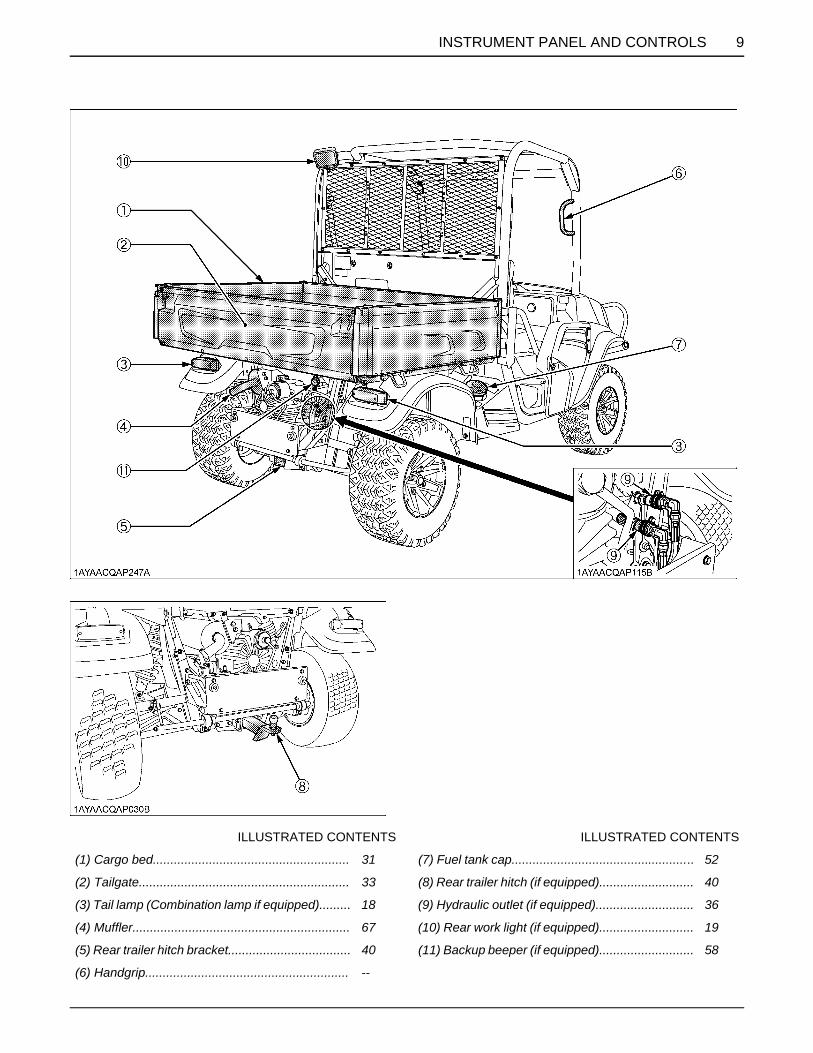
ILLUSTRATED CONTENTS ILLUSTRATED CONTENTS
(1) Cargo bed........................................................ 31 (7) Fuel tank cap.................................................... 52
(2) Tailgate............................................................ 33 (8) Rear trailer hitch (if equipped)........................... 40
(3) Tail lamp (Combination lamp if equipped)......... 18 (9) Hydraulic outlet (if equipped)............................ 36
(4) Muffler.............................................................. 67 (10) Rear work light (if equipped)........................... 19
(5) Rear trailer hitch bracket................................... 40 (11) Backup beeper (if equipped)........................... 58
(6) Handgrip.......................................................... --

10 PRE-OPERATION CHECK
PRE-OPERATION CHECK
DAILY CHECKTo prevent trouble from occurring, it is important to knowthe condition of the vehicle well. Check it before starting.To avoid serious injury or death:A Be sure to check and service the vehicle on a
level surface with the engine shut off and theparking brake "ON" and implement lowered tothe ground if equipped.
Check item- Walk around inspection- Check engine oil level- Check transmission fluid level- Check brake fluid level- Check hydraulic tank oil level- Clean hydraulic oil cooler net- Check coolant level- Clean grill, radiator screen (When used in a dusty place)- Check brake pedal- Check parking brake- Check indicators, gauges and meters- Check lights- Check seat belt and ROPS- Check joint boots- Check tire inflation pressure- Check backup beeper (if equipped)- Refuel (See "DAILY CHECK" in "PERIODIC SERVICE" section.)- Care of danger, warning and caution labels (See "DANGER, WARNING AND CAUTION LABELS" in "SAFE OPERATION" section.)

11OPERATING THE ENGINE
OPERATING THE ENGINE
To avoid serious injury or death:A Read and understand "Safe Operation" in front
of this manual.A Read and understand the danger, warning and
caution labels located on the vehicle.A To avoid the danger of exhaust fume
poisoning, do not operate the engine in aclosed building without proper ventilation.
A Never start engine while standing on ground.Start engine only from operator's seat.
A Make it a rule to set range gear shift lever to the"NEUTRAL" position and to place the HydraulicOutlet lever (if equipped) in "OFF" position andto place the hydraulic lift cylinder lever (ifequipped) to the "NEUTRAL" position beforestarting the engine.
A Make sure the engine hand throttle (ifequipped) is in its idle engine speed position.
A Do not use starting fluid or ether. A To protect the battery and the starter, make sure that
the starter is not continuously turned for more than 10seconds.
STARTING THE ENGINE1. Make sure the parking brake is set.
(1) Parking brake lever(2) Release button
(A) Pull to "PARK"
2. Make sure the door is properly secured. (if equipped)See "Locking and Unlocking the Door" in "STARTING" in "OPERATING THE VEHICLE" section.
3. Set the range gear shift lever to the "NEUTRAL" position.
(1) Range gear shift lever (L) LOW Range(H) HIGH Range(N) "NEUTRAL" POSITION(R) "REVERSE"

OPERATING THE ENGINE12
4. Lock the hydraulic lift cylinder lever or the hydraulic outlet lever to the "NEUTRAL" position with a restricting plate (if equipped).
(1) Hydraulic lift cylinder lever (if equipped) or Hydraulic outlet lever (if equipped)(2) Restricting plate (if equipped)
(A) "LOCK"
5. Push the speed control pedal downabout 1/2 way.
(1) Speed control pedal (A) "INCREASE"(B) "DECREASE"
6. Insert the key into the key switch and turn it "ON".
( ) "OFF" (Engine-Stop)( ) "ON" (Engine-Run)
( ) "GLOW" (Preheat)( ) "START" (Engine-Start)
ON........ A All the accessories can be used while theengine is stopped.
A Do not leave the key at "ON" position.The battery will be quickly discharged.Turn it back to the "OFF" position afteruse.
13OPERATING THE ENGINE
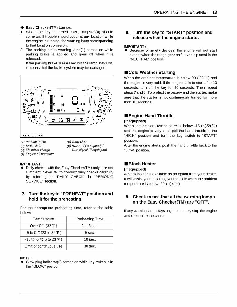
C Easy Checker(TM) Lamps:1. When the key is turned "ON", lamps(3)(4) should
come on. If trouble should occur at any location whilethe engine is running, the warning lamp correspondingto that location comes on.
2. The parking brake warning lamp(1) comes on whileparking brake is applied and goes off when it isreleased.If the parking brake is released but the lamp stays on,it means that the brake system may be damaged.
A Daily checks with the Easy Checker(TM) only, are notsufficient. Never fail to conduct daily checks carefullyby referring to "DAILY CHECK" in "PERIODICSERVICE" section.
For the appropriate preheating time, refer to the tablebelow:
A Glow plug indicator(5) comes on while key switch is inthe "GLOW" position.
A Because of safety devices, the engine will not startexcept when the range gear shift lever is placed in the"NEUTRAL" position.
BCold Weather StartingWhen the ambient temperature is below 0 (32 ) andthe engine is very cold. If the engine fails to start after 10seconds, turn off the key for 30 seconds. Then repeatsteps 7 and 8. To protect the battery and the starter, makesure that the starter is not continuously turned for morethan 10 seconds.
BEngine Hand Throttle[if equipped]When the ambient temperature is below -15 (-59 )and the engine is very cold, pull the hand throttle to the"HIGH" position and turn the key switch to "START"position.After the engine starts, push the hand throttle back to the"LOW" position.
BBlock Heater[if equipped]A block heater is available as an option from your dealer.It will assist you in starting your vehicle when the ambienttemperature is below -20 (-4 ).
If any warning lamp stays on, immediately stop the engineand determine the cause.
(1) Parking brake(2) Brake fluid(3) Electrical charge(4) Engine oil pressure
(5) Glow plug(6) Hazard (if equipped) / Turn signal (if equipped)
7. Turn the key to "PREHEAT" position and hold it for the preheating.
Temperature Preheating Time
Over 0 (32 ) 2 to 3 sec.
-5 to 0 (23 to 32 ) 5 sec.
-15 to -5 (5 to 23 ) 10 sec.
Limit of continuous use 30 sec.
8. Turn the key to "START" position and release when the engine starts.
9. Check to see that all the warning lamps on the Easy Checker(TM) are "OFF".

OPERATING THE ENGINE14
STOPPING THE ENGINE1. After slowing the engine to idle, turn the key to "OFF".2. Return the engine hand throttle (if equipped) to its idle
engine speed position.3. Remove the key.
WARMING UP
To avoid serious injury or death:A Be sure to set the parking brake during warm-
up.A Be sure to set the range shift lever to the
"NEUTRAL" position and lock both thehydraulic lift cylinder and the hydraulic outletlevers to the "OFF" position with restrictingplate (if equipped) during warm-up.
For 5 minutes after engine start-up, allow engine to warmup without applying any load. This is to allow oil to reachevery part of the engine. If load should be applied to theengine without this warm-up period, problems maydevelop such as seizure, breakage or premature wearmay develop.
BWarm-Up Transmission Oil in the Low Temperature Range
Hydraulic oil serves as transmission fluid. In cold weather,the oil may be cold with increased viscosity. This cancause delayed oil circulation or abnormally low hydraulicpressure for some time after engine start-up. This in turncan create problems with the hydraulic system.To prevent the above, observe the following instructions:Warm up the engine at about 50% of rated rpm accordingto the table below:
A Do not operate the vehicle under full load conditionuntil it is sufficiently warmed up.
JUMP STARTING
To avoid serious injury or death:A Keep cigarettes, sparks, and flames away from
battery.A If vehicle battery is frozen, do not jump start
engine.A Do not connect other end of negative jumper
cable to negative terminal of vehicle battery.A The parts such as the muffler may be hot. Be
careful not to get burned in connecting jumpercables.
When jump starting the engine, follow the instructionsbelow to safely start the engine.1. Bring helper vehicle with a battery of the same voltage
as the disabled vehicle within easy cable reach. "THEVEHICLES MUST NOT TOUCH".
2. Engage the parking brake of both vehicles and put theshift lever in neutral. Shut the engine off.
3. Put on safety goggles and rubber gloves.4. Ensure the vent caps are securely in place. (if
equipped)5. Attach the red clamp to the positive (red, (+) or pos.)
terminal of the dead battery and clamp the other endof the same cable to the positive (red, (+) or pos.)terminal of the helper battery.
6. Clamp the other cable to the negative (black, (-) orneg.) terminal of the helper battery.
7. Clamp the other end to the engine block or frame ofthe disabled vehicle as far from the dead battery aspossible.
8. Start the helper vehicle and let its engine run for a fewmoments. Start the disabled vehicle.
9. Disconnect the jumper cables in the exact reverseorder of attachment. (Steps 7, 6 and 5).
Ambient temperature Warm-up time requirement
Above 0 (32 ) Approx. 5 minutes
-10 to 0 (14 to 32 ) 5 to 10 minutes
-20 to -10 (-4 to 14 ) 10 to 15 minutes
Below -20 (-4 ) More than 15 minutes

15OPERATING THE ENGINE
A This vehicle has a 12 volt negative (-) ground startingsystem.
A Use only same voltage for jump starting.A Use of a higher voltage source could result in severe
damage to vehicle's electrical system.Use only matching voltage source when "Jumpstarting" a low or dead battery.
(1) Dead battery(2) Jumper cables(3) Helper battery

16 OPERATING THE VEHICLE
OPERATING THE VEHICLE
OPERATING NEW VEHICLEHow a new vehicle is handled and maintained determinesthe life of the vehicle.A new vehicle just off the factory production line has beentested, but the various parts are not accustomed to eachother, so care should be taken to operate the vehicle forthe first 50 hours at a slower speed and avoid excessivework or operation until the various parts become "broken-in." The manner in which the vehicle is handled during the"breaking-in." period greatly affects the life of your vehicle.Therefore, to obtain the maximum performance and thelongest life of the vehicle, it is very important to properlybreak-in your vehicle. In handling a new vehicle, thefollowing precautions should be observed.BDo not Operate the Vehicle at Full Speed for the First 50 Hours
A Do not start quickly nor apply the brakes suddenly.A In winter, operate the vehicle after fully warming up the
engine.A Do not run the engine at speeds faster than
necessary.A On rough roads, slow down to suitable speeds.
Do not operate the vehicle at fast speed. The aboveprecautions are not limited only to new vehicles, but toall vehicles. But it should be especially observed in thecase of new vehicles.
BChanging Lubricating Oil for New Vehicles
The lubricating oil is especially important in the case of anew vehicle. The various parts are not "broken-in" and arenot accustomed to each other. Small pieces of metal gritmay develop during the operation of the vehicle; and thismay wear out or damage the parts. Therefore, care shouldbe taken to change the lubricating oil a little earlier thanwould ordinarily be required. For further details of changeinterval hours, see "MAINTENANCE" section.
STARTING
BLocking and Unlocking the Door
To avoid serious injury or death:A Secure the doors properly.
Secure the door properly to lock. Pull up the door handleto unlock.
1. Make sure the door is properly secured. (if equipped)
(1) Door(2) Door handle
(A) "UNLOCK"
2. Fasten the seat belt.
17OPERATING THE VEHICLE
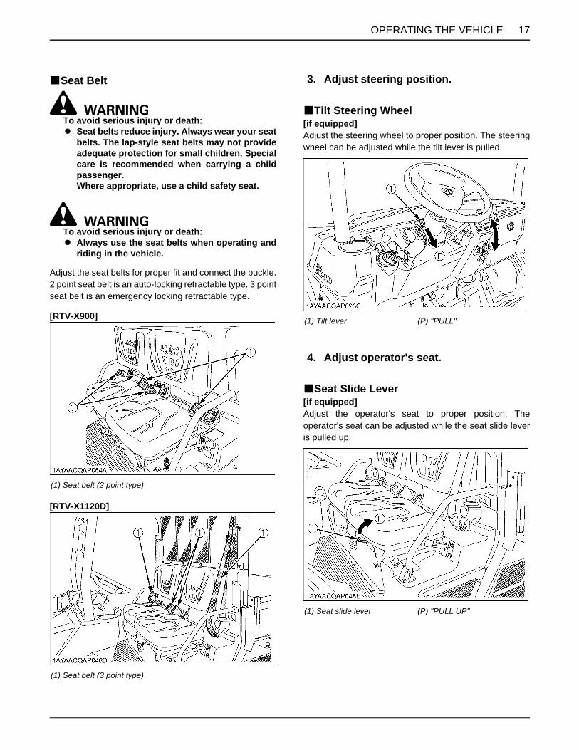
BSeat Belt
To avoid serious injury or death:A Seat belts reduce injury. Always wear your seat
belts. The lap-style seat belts may not provideadequate protection for small children. Specialcare is recommended when carrying a childpassenger.Where appropriate, use a child safety seat.
To avoid serious injury or death:A Always use the seat belts when operating and
riding in the vehicle.
Adjust the seat belts for proper fit and connect the buckle.2 point seat belt is an auto-locking retractable type. 3 pointseat belt is an emergency locking retractable type.
[RTV-X900]
[RTV-X1120D]
BTilt Steering Wheel[if equipped]Adjust the steering wheel to proper position. The steeringwheel can be adjusted while the tilt lever is pulled.
BSeat Slide Lever[if equipped]Adjust the operator's seat to proper position. Theoperator's seat can be adjusted while the seat slide leveris pulled up.
(1) Seat belt (2 point type)
(1) Seat belt (3 point type)
3. Adjust steering position.
(1) Tilt lever (P) "PULL"
4. Adjust operator's seat.
(1) Seat slide lever (P) "PULL UP"

OPERATING THE VEHICLE18
BHead Light SwitchThe head light switch is operative when the key switch isin the "ON" position. Turn on the key switch and turn the head light switchclockwise to the "ON" position, the head lights light up. Turn the head light switch counterclockwise to the "OFF"position to turn off the head light.
A Turning the head light switch to the "ON" positioncauses the following lamps to light simultaneously.(1) Tail lights (lamps at the rear portions of the
vehicle)
BHazard Light Switch[if equipped]Press the hazard light switch, the hazard light flash alongwith the indicator on the instrument panel. Press the hazard light switch again to turn off the hazardlight.
A The hazard light switch is operative when the keyswitch is in either the "ON" or "OFF" position.Be careful that leaving the switch "ON" causes thebattery to run out.
BTurn Signal Light Switch[if equipped]To indicate a right turn, turn the turn signal light switchclockwise.To indicate a left turn, turn the turn signal light switchcounter-clockwise.When the left or right signal is activated, the indicatedturning light will flash and the other will stay on.The indicator lamp at the instrument panel also flasheslike the above.
A The turn signal light switch is only operative when thekey switch is in the "ON" position.
A If the hazard light switch is pressed to the "ON"position while the turn signal is activated, the indicatedturning light will flash and the other will stay on.
A Be sure to return switch to center position after turning.
5. Selecting light switch position.
(1) Head light switch (A) Head lights "OFF"(B) Head lights "ON"
(1) Turn signal light switch (A) "RIGHT TURN"(B) "LEFT TURN"

19OPERATING THE VEHICLE
BHorn ButtonThe horn switch is operative when the key switch is ineither the "ON" or "OFF" position.The horn will sound when the horn button is pressed.
BWork Light (Front)[if equipped]When the key switch is turned to the "ON" position and thefront work light switch is turned to the "ON" position, thework light comes on.
BWork Light (Rear)[if equipped]When the key switch is turned to the "ON" position and theslide switch at the rear of each work light is slid to the "ON"position, the work light comes on. When the slide switchis slid to the "OFF" position, the light goes off.After the slide switch for each work light is shifted to the"OFF" position, turn the key switch to the "OFF" position.
(1) Head light(2) Hazard / Turn signal light (if equipped)(3) Tail lamp (Combination lamp if equipped)
(1) Horn button
(1) Front work light (if equipped)(2) Front work light switch (if equipped)
(A) "ON"(B) "OFF"
(1) Rear work light (if equipped)(2) Rear work light switch (if equipped)
(A) "ON"(B) "OFF"

OPERATING THE VEHICLE20
BBrake Pedal
To avoid serious injury or death:A If the operator suddenly brakes, an accident
may occur due to loss of control or the shiftingforward of heavy loads.
A When driving on icy, wet or loose surface,operate at reduced speed to avoid skidding andloss of steering control.
The brake pedal is the left pedal on the foot board.Depress the pedal to slow or stop the vehicle.
BRange Gear Shift Lever
To avoid serious injury or death:A Avoid changing range gear shift lever when
ascending or descending a slope.A Before ascending or descending a slope, shift
to the "L" range to control the vehicle speed.A If you shift gears while ascending or
descending a slope, be prepared to use thebrake to maintain control.
A Operate in reverse at slow speeds to maintaincontrol.
1. The range gear shift lever can only be shifted whenvehicle is completely stopped and the speed controlpedal is in the "NEUTRAL" position.
2. To avoid transmission and shift linkage damage,completely stop the vehicle using the brake pedalbefore shifting gears.
3. Select proper gear and engine speed depending onthe type of job.
4. Before dismounting vehicle, shift the range gear shiftlever to the "NEUTRAL" position and set parkingbrake.
A When range gear shift lever is hard to engage, do notforce the lever. Set the parking brake, slightly depressthe speed control pedal and release it to neutralposition, then shift the lever.When the lever is hard to disengage, do not force thelever.Depress the brake pedal fully, then shift the lever.
A An accident may occur with erratic shifting operation.
6. Checking the brake pedal.
(1) Brake pedal
7. Start the engine.See "OPERATING THE ENGINE" section.
8. Selecting the travel speed.
(1) Range gear shift lever (L) LOW Range(H) HIGH Range(N) "NEUTRAL" POSITION(R) "REVERSE"

21OPERATING THE VEHICLE
A Failure to completely engage the range gear cancause the vehicle to coast on slopes.
B4WD Lever
To avoid serious injury or death:A Do not engage the front wheel drive when
traveling at road speed.A When driving on icy, wet or loose surface,
operate at reduced speed to avoid skidding andloss of steering control.
A An accident may occur if the vehicle issuddenly braked, such as by heavy towedloads shifting forward causing loss of control.
A The braking characteristics are differentbetween 2 and 4 wheel drive. Be aware of thedifference and use carefully.
A Use the lever to engage the front wheels with thevehicle stopped. Shift the lever to "4WD" to engage thefront wheel drive. When the lever is in "4WD" position, the 4WD indicatorcomes on.
A Tires will wear quickly if front wheel drive is engagedon paved roads.
C Front wheel drive is effective for the followingjobs:
1. When greater pulling force is needed, such as workingin a wet field, when pulling a trailer, or when workingwith a front-end blade.
2. When working in sandy soil.
BParking Brake LeverTo release the parking brake, depress the brake pedal,push release button and push up parking brake lever. Depressing the brake pedal makes release force smaller. Make sure that indicator in the Easy Checker(TM) goesoff.
(1) 4WD lever (A) "2WD"(B) "4WD"
(1) 4WD indicator
9. Unlock the parking brake and start slowly.
(1) Parking brake lever(2) Release button
(A) "RELEASE"(B) "PUSH"

OPERATING THE VEHICLE22
BSpeed Control PedalUse the speed control pedal when traveling. Push downon it for higher speed.
STOPPINGBStopping1. Release the speed control pedal.2. Step on the brake pedal.3. After the vehicle has stopped, put the range gear shift
lever in neutral, and set the parking brake.
CHECK DURING DRIVINGBImmediately Stop the Engine if:A The engine suddenly slows down or accelerates.A Unusual noises suddenly occur.A Exhaust fumes suddenly become very dark.
While driving, check the following items to see that all theparts are functioning normally.
BEasy Checker(TM)If the warning lamps in the Easy Checker(TM) come onduring operation, immediately stop the engine, and findthe cause as shown below.Never operate the vehicle with an Easy Checker(TM)lamp on.
Engine oil pressureIf the oil pressure in the engine goes below theprescribed level, the warning lamp in the EasyChecker(TM) will come on.If this should happen during operation, and it does notgo off when the engine is accelerated, check level ofengine oil.(See "Checking Engine Oil Level" in "DAILY CHECK"in "PERIODIC SERVICE" section.)
Electrical chargeIf the alternator is not charging the battery, the EasyChecker(TM) will come on.If this should happen during operation, check theelectrical charging system or consult your localKUBOTA Dealer.
Low brake fluid levelIf the brake fluid goes below the prescribed level, thewarning lamp in the Easy Checker(TM) will come on.If this should happen during operation, check to seethat there is no oil leak in the brake system, and thenadd Dot3 brake fluid. (See "Checking Brake Fluid Level" in "DAILY CHECK"in "PERIODIC SERVICE" section.)
VHT oil temperatureIf the VHT oil is overheated, the warning lamp willcome on and the buzzer will sound.Check the vehicle by referring to"TROUBLESHOOTING" section.
Parking brakeIf the parking brake indicator is on during operation,release the parking brake lever immediately.The parking brake indicator in the Easy Checker(TM)comes on if the parking brake is applied.
Seat belt [RTV-X1120D only]With the key switch "ON", when the operator orpassenger does not fasten the seat belt, seat beltwarning lamp comes on.
(1) Speed control pedal (A) "INCREASE"
(1) Easy Checker(TM)(2) Coolant temperature gauge(3) Fuel gauge

23OPERATING THE VEHICLE
BFuel GaugePark the vehicle on a flat place.When the key switch is "ON", the fuel gauge indicates thefuel level.Be careful not to empty the fuel tank. Otherwise air mayenter the fuel system.Should this happen, the system should be bled. (See"Bleeding Fuel System" in "SERVICE AS REQUIRED" in"PERIODIC SERVICE" section.)
BCoolant Temperature Gauge
To avoid serious injury or death:A Do not remove radiator cap until coolant and
engine temperature has cooled. Then loosencap slightly to the stop to relieve any pressurebefore removing cap completely.
1. With the key switch "ON" the coolant temperaturegauge indicates the temperature of the coolant.
2. If the engine is overheated, the warning lamp will comeon and the buzzer will sound. Check the vehicle byreferring to "TROUBLESHOOTING" section.
A If the engine overheat and VHT overheat occurtogether, do not stop the engine. When it is safe to doso, remove the engine load and keep the engine idlingto allow cool down to occur.After the warning lamps go off, wait for 5 minutes, andstop the engine. See "TROUBLESHOOTING" section.
(1) Fuel gauge(2) Fuel level warning lamp
(1) Coolant temperature gauge(2) Overheat warning lamp

OPERATING THE VEHICLE24
BHourmeter and OdometerWhen the key is turned to the "ON" position and theengine is not running, the hourmeter is displayed. When the key is the "ON" position and the engine isrunning, the odometer is displayed.The hourmeter indicates in 5 digits the hours the vehiclehas been used; the last digit indicates 1/10 of an hour.The odometer indicates in 5 digits the distance the vehiclehas been used; the last digit indicates 1/10 of a mile.
BSpeedometerThe speedometer indicates the traveling speed.
(1) Hourmeter
(1) Odometer
(1) Speedometer

25OPERATING THE VEHICLE
PARKINGBParking Brake Lever
To avoid serious injury or death:BEFORE DISMOUNTING VEHICLE A ALWAYS SET PARKING BRAKE AND LOWER
ALL IMPLEMENTS TO THE GROUND.Leaving transmission in gear with the enginestopped will not prevent vehicle from rolling.
A STOP THE ENGINE AND REMOVE THE KEY.
1. Stop the vehicle on a level surface.2. To set the parking brake, depress the brake pedal and
pull the parking brake lever to the rear engagedposition.
3. To release the parking brake, depress the brakepedal, push release button and push up parking brakelever. Depressing the brake pedal makes releaseforce smaller. Make sure that indicator in the EasyChecker(TM) goes off.
A If the vehicle is operated with the parking brakeapplied, the brake will be damaged.
ACCESSORYB12V Electric OutletThe 12 volt power point is located on the front-panel. Anauxiliary light or other devices may be connected to thisoutlet.
C This outlet is powered when the key switch is ineither the "ON" or "OFF" position.
Remove accessory when not in use to avoid battery draindown.
C Do not connect a light or other device that drawsmore than 120 watts to this power point, or thebattery may discharge very rapidly or the outletmay fail.
A Do not use as a cigarette lighter.A Do not use when wet.A Make sure that the cap is closed when the outlet is not
used.
BUtility Box
(1) Parking brake lever(2) Release button
(A) "RELEASE"(B) "PUSH"
(1) 12V electric outlet
(1) Utility Box

OPERATING THE VEHICLE26
BGlove Box (Std.) and Glove Box Cover (if equipped)
Insert the key into the knob slot and turn itcounterclockwise to lock. Insert the key into the knob slot and turn it clockwise tounlock.
OPERATING TECHNIQUESBDifferential Lock
To avoid serious injury or death due to loss ofsteering control:A Do not operate the vehicle at high speed with
differential lock engaged.A Do not attempt to turn with the differential lock
engaged.A Be sure to release the differential lock before
making a turn in field conditions.
If one of the rear wheels should slip, step on thedifferential lock pedal. Both wheels will then turn together,reducing slippage.Differential lock is maintained while the pedal isdepressed or may be held by using differential lock holder.
C Handling the retaining device for differential lock1. Pull the differential lock holder up while the differential
lock pedal is depressed.2. Release the pedal before your hand leaves the
differential lock holder. The differential lock is then maintained even if yourfoot leaves the pedal.
3. The lock is released when the foot pedal is depressedagain.
A When using the differential lock, always slow thevehicle and engine down.
A To prevent damage to power train, do not engagedifferential lock when one wheel is spinning and theother is completely stopped.
(1) Glove box(2) Glove box cover (if equipped)(3) Knob (if equipped)
(A) "LOCK"
(1) Differential lock pedal(2) Differential lock holder
(A) Depress to "ENGAGE"(B) Release to "DISENGAGE"

27OPERATING THE VEHICLE
BDirections for Use of Power Steering1. Power steering is activated only while the engine is
running. While the engine is stopped, the vehiclefunctions in the same manner as vehicle withoutpower steering.
2. When the steering wheel is turned all the way to thestop, the relief valve is activated. Do not hold thesteering wheel in this position for a long period of time.
3. Avoid turning the steering wheel while the vehicle isstopped, otherwise tires may wear out sooner.
4. The power steering mechanism makes the steeringeasier. Be careful when driving at high speeds.
5. Do not operate the hydraulic lift cylinder lever (orhydraulic outlet lever) when driving. Otherwise loss of control or failure of the powersteering could occur.
BUnfamiliar Terrain
To avoid serious injury or death:A Be sure to check for hidden obstacles or
hazards before driving in a new area.A Keep your speed down until you know the area
well.A Use existing trails and stay away from
hazardous areas such as steep, rocky slopesor swamps.
A Be cautious when visibility is limited, as youmay not be able to see obstacles in your path.
BDriving in Reverse
To avoid serious injury or death:A Turn around, look down and behind you before
backing up to be sure there are no obstacles orpeople in your way.
A Depress speed control pedal gradually andback cautiously.
A To stop while driving in reverse take your footoff the speed control pedal and gradually applythe brake.
A Do not suddenly engage the brake.

OPERATING THE VEHICLE28
BDriving in "4WD"
To avoid serious injury or death:A Do not drive in "4WD" on paved surfaces.
For the maximum traction, shift the range gear shift leverinto low range and use "4WD" on steep slopes or whenstuck in the mud, with differential locked if necessary.
BTurning the Vehicle
To avoid serious injury or death:A Reduce vehicle speed before entering the turn
and maintain an even speed through the turn.A Do not make sharp turns in order to avoid loss
of control or tipping.

29OPERATING THE VEHICLE
BHills
To avoid serious injury or death:A Do not turn sideways on a hill, or the vehicle
may roll over.A Always go straight up or down the hill.A Slow down until you can get a clean view of the
other side at the crest of a hill.A If the engine stalls on a steep slope, roll slowly
straight down, using the brake.A Stop and look for obstacles before descending
a hill.
BTraversing Hillsides
To avoid serious injury or death:A Reduce vehicles speed to prevent tipping or
loss of control.A Do not traverse hillsides that are slippery or
covered with rocks or obstacles which maycause you to tip over.
BSliding and Skidding
To avoid serious injury or death:A Drive slowly and carefully when you are unsure
or unprepared for the surface.A Do not apply heavy braking force or accelerate
when skidding to prevent loss of control.A Use 4WD and maintain low speeds on areas
covered with clay, mud, ice or snow to preventuncontrolled skidding.

OPERATING THE VEHICLE30
BDriving through Water
To avoid serious injury or death:A Do not drive through water whenever it is
possible.A Drive slowly across shallow water and choose
a location to enter and exit the water where thebanks are not too steep or slippery.
A Before entering water, check for rocks, holes orother obstacles that may cause overturn, stuckor submerged.
A Never operate the vehicle in the fast flowingwater or in water deeper than the bottom edgeof the axle caps.
OPERATING HAND THROTTLE[if equipped]A Pull the hand throttle while pushing the button, and the
engine speed increases.A Push the hand throttle while pushing the button, and
the engine speed decreases.A Fine-tune engine speed by turning the hand throttle.
A Do not use the hand throttle while driving the vehicle,always push the hand throttle back to the "LOW"position.Before driving the vehicle, confirm the hand throttle tobe positioned to the "LOW" position.
STATIONARY HYDRAULIC OUTLET[if equipped]To use the hydraulic outlet system, start the hydraulicoutlet system in the following steps.1. Apply the parking brake and place chocks at the tires.2. Make sure the shift levers are in "NEUTRAL", and start
the engine.3. Operate the hydraulic outlet lever.
(See "HYDRAULIC OUTLET" in "HYDRAULICOUTLET" section.)
4. Set the engine speed to provide recommended fluidrate. (Refer to the implement operator's manual.)
A Do not use a hydraulic implement which has ahydraulic motor except those approved by Kubota.
(1) Axle cap
(1) Hand throttle (if equipped)(2) Button
(A) "PUSH" "HIGH"
"LOW"

31CARGO BED
CARGO BED
CARGO BEDBGeneral CautionTo avoid serious injury or death:A Never carry passengers in the cargo bed. They can be tossed about or even thrown off causing serious
injury or death.A Never raise the cargo bed when it is loaded. (There is an exception. Only the vehicle equipped with hydraulic
dump may do this operation at operator's seat after appropriate confirmation of safety.)A Driving with the cargo bed tilted may be hazardous.
Always lower the bed and lock the hydraulic lift cylinder lever (if hydraulic dump is equipped) or latch thebed (if hydraulic dump is not equipped) before driving.
A Be careful not to put any part of your body, such as hands or arms, between the bed and vehicle.A Drive slowly when it is loaded.
BMax. Cargo LoadNever carry loads exceeding cargo bed capacity and the Permissible Cargo Load (PCL).PCL = PC - (operator + passenger + opt. + acc. + cabin) weight
CBC (Cargo bed capacity): 500 kg (1100 lbs.)PC: Payload CapacityOP: OperatorPA: Passengeropt.: optionacc.: accessorycabin: 125 kg (275 lbs.)
[Payload Capacity (PC)]
ModelRTV-X900 RTV-X1120D
General Purpose model Worksite model Worksite model
Payload capacity 755 kg (1664 lbs.) 725 kg (1598 lbs.) 685 kg (1510 lbs.)
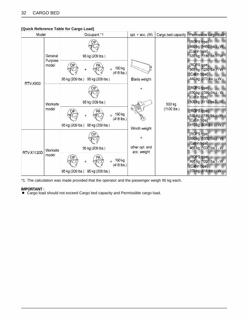
32 CARGO BED
[Quick Reference Table for Cargo Load]
*1: The calculation was made provided that the operator and the passenger weigh 95 kg each.
A Cargo load should not exceed Cargo bed capacity and Permissible cargo load.

33CARGO BED
BCargo Bed Tailgate
To avoid serious injury or death:A Do not apply a load to the tailgate while the
tailgate is open, as the wire loop may break,resulting in injury or loss of load.
A Do not place fingers or hands between thetailgate and the arm (latch) when closing, orfingers or hands may be pinched.
For loading and unloading, the tailgate of the cargo bedcan be opened.The tailgate is held level to the cargo bed floor with wireloops.Do not move the vehicle with the tailgate fully lowered.
1. Raise the arms (latch) at each end of the tailgate andopen the tailgate.
2. Close the tailgate by lifting it and pushing it firmlyclosed. Push the arms (latch) down to make sure thelatches stay securely closed.
A TO AVOID TAILGATE DAMAGE:Remove the rear trailer hitch when wire loop isremoved and cargo bed is raised.
BRaising and Lowering the Cargo Bed[if hydraulic dump is equipped]
To avoid serious injury or death:A Make sure the vehicle is on a firm, level surface
and the parking brake is applied before raisingthe cargo bed.
A If the vehicle is facing uphill with cargo bedraised, the weight of the cargo bed may causethe vehicle tip.
A When servicing under raised bed with liftcylinder, make sure safety support is properlymounted.
A Do not operate the hydraulic lift cylinder lever(or hydraulic outlet lever) when driving.Otherwise loss of control or failure of thepower steering could occur.
C To raise the cargo bed1. Start engine.2. Release the restricting plate.3. Pull up the hydraulic lift cylinder lever to raise the
cargo bed.4. Return the hydraulic lift cylinder lever to the
"NEUTRAL" position immediately after raising thecargo bed.
5. Mount the safety support.
C To mount the safety support1. Push the safety support and take off it from the hook.2. Turn the safety support to set.
C To lower the cargo bed1. Remove the safety support.2. Shift the hydraulic lift cylinder lever to the "DOWN"
position and then lower the cargo bed.3. After making sure that the bed has been lowered to the
lowest position, return the lever to the "NEUTRAL"position and then lock the lever with the restrictingplate.
A Do not hold the lever in the "UP" or "DOWN" positiononce the remote cylinder has reached the end of itsstroke, as this will cause oil to flow through the reliefvalve. Forcing oil through the relief valve for extendedperiods will overheat the oil.
A Continuing to use the lever may cause oil temperatureto rise excessively. The use of oil at a hightemperature causes the seals to become damagedand fail.
(1) Tailgate (2) Arm (latch) (3) Wire loop

CARGO BED34
C Using the "FLOAT" position1. If the cargo bed cannot be raised or lowered due to
trouble with the engine or hydraulic system, shift thelever to the "FLOAT" position. The cargo bed can beraised or lowered manually.
(1) Hydraulic lift cylinder lever (if equipped)(2) Restricting plate (if equipped)
(U) "UP"(N) "NEUTRAL"(D) "DOWN"(F) "FLOAT with Detent"
(1) Safety support (A) "UNLOCK"(B) "MOVE"(C) "TURN"
(1) Safety support

35CARGO BED
BRaising and Lowering the Cargo Bed [without hydraulic dump]
To avoid serious injury or death:A Always lower and latch the bed before driving.A Be careful not to catch any part of your body,
such as hands or arms, between the bed andvehicle frame when lifting and lowering thebed. To prevent injury, use only the handgripsprovided.
The cargo bed may be tilted by releasing the latches oneach side, and then lifting the bed with the handgrips.Support the bed in the raised position with the safetysupport.
(1) Latch(2) Handgrip
(A) "LOCK"(B) "RELEASE"
(1) Safety support

36 HYDRAULIC OUTLET
HYDRAULIC OUTLET
HYDRAULIC OUTLET[if equipped]BHydraulic Outlet Lever
To avoid serious injury or death:A Leaving the vehicle while the engine runs
requires shifting the range gear shift lever tothe "NEUTRAL" position, and locking theparking brake lever firmly.
C Steps for operation1. Remove the hydraulic hoses for hydraulic dump, and
clamp the hoses so that they are not caught in rotaryobject.
2. Check the outlet and return directions of the hydrauliccoupler and then connect the hydraulic hose.
3. Make sure that the hydraulic lever at the side of theworking vehicle is in the "NEUTRAL" position.
4. Shift the hydraulic outlet lever to the "A" position or "B"position according to the implement of use.
5. Lock the hydraulic outlet lever at the "NEUTRAL"position with the restricting plate after use.
A Do not hold the lever in the "PULL" or "PUSH" positiononce the remote cylinder has reached the end of itsstroke, as this will cause oil to flow through the reliefvalve. Forcing oil through the relief valve for extendedperiods will overheat the oil.
A Continuing to use the lever may cause oil temperatureto rise excessively. The use of oil at a hightemperature causes the seals to become damagedand fail.
A Shift the hydraulic outlet lever to the "NEUTRAL"position and then stop the engine.
A Because of the safety devices, the engine will not startexcept when the hydraulic outlet lever is placed in the"OFF" position and range gear shift lever is placed inthe "NEUTRAL" position.
A Do not operate the hydraulic outlet lever when driving. Otherwise loss of control or failure of the powersteering could occur.
A Do not use a hydraulic implement which has ahydraulic motor except those approved by Kubota.
(1) Hydraulic outlet lever (if equipped)(2) Restricting plate (if equipped)
(A) "ON"(N) "OFF"(B) "ON"(F) "FLOAT with Detent"
(1) Hydraulic outlet (if equipped) [yellow](2) Hydraulic outlet (if equipped) [white]
OutletReturn
Lever Pull ( ) Push ( )
Port[yellow] OUT IN
[white] IN OUT

37HYDRAULIC OUTLET
BHydraulic Outlet Valve Coupler Connecting and Disconnecting
To avoid serious injury or death:A Stop the engine and relieve pressure before
connecting or disconnecting lines.A Do not use your hand to check for leaks.A Make sure couplers are locked securely after
connecting them.A Always wear protective gloves when handling
hydraulic tools, hoses and couplers.
C Connecting1. Remove dust plugs.2. Clean both couplers.3. Insert the implement coupler to the vehicle hydraulic
coupler.4. Pull the implement coupler slightly to make sure
couplers are firmly connected.
C Disconnecting1. Lower the implement first to the ground to relieve
hydraulic pressure in the hoses.2. Clean the couplers.3. Relieve pressure by moving hydraulic control levers
with engine shut off.4. Pull the hose straight from the hydraulic coupler while
pulling the ring to release it.5. Clean oil and dust from the coupler, then replace the
dust plugs.
A Your local KUBOTA Dealer can supply parts to adaptcouplers to hydraulic hoses.
(1) Ring of female coupler(2) Male coupler
(1) Ring of female coupler(2) Male coupler

38 TIRES AND WHEELS
TIRES AND WHEELS
TIRESTo avoid serious injury or death:A Do not attempt to mount a tire on a rim. This
should be done by a qualified person with theproper equipment.
A Always maintain the correct tire pressure.Do not inflate tires above the recommendedpressure shown in the operator's manual.
A Do not use tires other than those approved byKUBOTA.
BInflation PressureThough the tire pressure is factory-set to the prescribedlevel, it naturally drops slowly in the course of time. Thus,check it everyday and inflate as necessary.
BTire Type and UseC Heavy duty work site tire
C Turf tire
C All terrain vehicle tire
Tire sizes Inflation Pressure
25 x 10 - 12 HDWS, Front & Rear
140 kPa(1.4 kgf/cm , 20 psi)
25 x 12 - 12 Turf,Front & Rear
25 x 10 - 12 ATV,Front & Rear
(1) Ground (A) "INSUFFICIENT"(B) "NORMAL"(C) "EXCESSIVE"

39TIRES AND WHEELS
WHEELS
To avoid serious injury or death:A Support vehicle securely on stands before
removing a wheel.A Never operate vehicle with loose wheel bolts
and nuts.
A When re-fitting a wheel, tighten the bolts and nuts tothe following torques then recheck after driving thevehicle 200 m (220 yards) and thereafter according toservice interval.
SHOCK ABSORBERSBShock Absorber Spring Adjustment
To avoid serious injury or death:A For shock absorber spring adjustment, make
sure to consult your local KUBOTA dealer.
The front and rear shock absorber springs can beadjusted for different riding and loading condition.
[Shock absorber position]
(1) Tightening torque (bolts and nuts) Aluminum wheel: 90 to 110 N-m (9.2 to 11.2 kgf-m) (66.4 to 81.1 lbf-ft) Steel wheel: 108 to 130 N-m (11.1 to 13.2 kgf-m) (79.7 to 95.8 lbf-ft)
Position Spring Load
1 Stronger Heavy
2
3 (default)
4
5 Weaker Light

40 TOWING AND TRANSPORTING
TOWING AND TRANSPORTING
TOWING AND TRANSPORTINGBRear Trailer Hitch[if equipped]To avoid serious injury or death:A Always tow a load slowly enough to maintain
control and avoid tipping.A To provide adequate braking ability and
traction, do not tow a load unless vehicle cargobed is loaded or attachment is installed.
A Attach a trailer to the trailer hitch only.
The rear trailer hitch load is referred to "VEHICLELIMITATIONS" section. When towing other equipment,use a safety chain.
BFront Trailer Hitch[if equipped]
To avoid serious injury or death:A Do not tow this vehicle unless all the functions
of the vehicle are properly working, since themalfunction of steering operation or brakingmay cause an accident.
Use the front trailer hitch for greater maneuverability inconfined areas such as a barn.The front trailer hitch load is referred to "VEHICLELIMITATIONS" section.
(1) Rear trailer hitch (if equipped)(2) Hitch pin (if equipped)
(1) Front trailer hitch (if equipped)(2) Hitch pin (if equipped)

41TOWING AND TRANSPORTING
BWinch Mount BracketMounting the optional winch always requires reading theinstruction manual attached to the winch thoroughlybefore using it.
BTransport the Vehicle SafelyPay attention to the points below when transporting thevehicle.1. Apply the parking brake and place chocks against the
front and rear tires.2. Secure the portions of the vehicle, which are shown in
the figure below, by using adequate straps or chains.3. When transporting vehicle on truck or trailer, always
comply with Federal and/or Local regulations forsecurement.
A Do not apply the straps and chains to the rearstabilizer.
Follow below when towing the vehicle: Otherwise, thevehicle's powertrain may get damaged.A Set the all shift levers to "NEUTRAL" position.A If possible, start engine and select 2WD, if creep
speed is fitted ensure that it is disengaged.A Tow the vehicle using its front hitch or drawbar.A Never tow faster than "10 km/h (6.2 mph)".
(1) Winch mount bracket
(1) Front guard(2) Heavy-duty strap
(1) Lower arm(2) Heavy-duty strap
(A) Rear stabilizer

42 MAINTENANCE
MAINTENANCE
To avoid serious injury, death or vehicle damage:A Be sure you have sufficient knowledge, experience, the proper replacement parts and tools before you
attempt any vehicle maintenance task.A If you don't have the knowledge and equipment which are necessary to perform the maintenance task,
consult your local KUBOTA Dealer.A Have your local KUBOTA Dealer perform inspection items which are marked *6 in the chart below.
SERVICE INTERVALS
A The jobs indicated by must be done after the first 50 hours of operation.*1 The initial 50 hours should not be a replacement cycle.*2 Air cleaner should be cleaned more often in dusty conditions than in normal conditions.*3 Every 1000 hours or every 1 year whichever comes faster.*4 Replace if any deterioration (crack, hardening, scar, or deformation) or damage occurred.*5 Every 2000 hours or every 2 years whichever comes faster.*6 Consult your local KUBOTA Dealer for this service.*7 When the battery is used for less than 100 hours per year, check the battery condition by reading the indicator annually.A The items listed below (@marked) are registered as emission related critical parts by KUBOTA in the U.S.EPA non road
emission regulation. As the engine owner, you are responsible for the performance of the required maintenance on theengine according to the below instruction. Please see Warranty Statement in detail.
No. ItemsIndication of Hour Meter After
700 hrsRef.Page50 100 150 200 250 300 350 400 450 500 550 600 650 700
1 Engine start system Check every50 hrs 60
2 Greasing Apply every50 hrs 59
3 Muffler[Spark arrester] Clean every
100 hrs 67
4 Wheel fastener torque Check every
100 hrs 62 *1
5 Battery condition Check every100 hrs 64 *7
6 Alternator belt Adjust every100 hrs 63
7 VHT neutral spring Check every100 hrs 61 *6
8 VHT pressure release Check every
100 hrs 61 *6
9 Toe-in Adjust every100 hrs 66
10 Fuel filter element
Check every100 hrs 63
@
Replace every400 hrs 76 *6

43MAINTENANCE
11 Air cleaner element
Clean every100 hrs 62 *2
@
Replaceevery
1000 hrsor 1 year
76 *3
12 Engine oil filter Replace every200 hrs 69 *1
13 Engine oil Change every200 hrs 69 *1
14Transmission oil filter (VHT)(Yellow color)
Replace every200 hrs 70 *1
15Transmission oil filter (Suction)(Black color)
Replace every200 hrs 71 *1
16 Brake pedal Check every200 hrs 72 *1
*6
17 Parking brake Adjust every200 hrs 68 *1
18 Brake light switch Check every200 hrs 73 *1
19 Front brake case Check every200 hrs 73 *1
20 Hydraulic tank oil Change every200 hrs 71
21 Tire wear Check every300 hrs 74 *1
22 Transmission fluid Change every400 hrs 75
23 Front axle case oil Change every400 hrs 76
24 Front knuckle case oil Change every
400 hrs 74
25 Engine valve clearance Adjust every
800 hrs 76 *6
26Fuel injection nozzle Injection pressure
Check every1500 hrs 76 *6 @
27 Cooling system Flush
every2000 hrs
or2 years
76 *5
28 Coolant Change
every2000 hrs
or2 years
76 *5
29 Injection pump Check every3000 hrs 78 *6 @
30 Fuel line
Check every1 year 78 *4
@
Replace every4 years 82
No. ItemsIndication of Hour Meter After
700 hrsRef.Page50 100 150 200 250 300 350 400 450 500 550 600 650 700

44 MAINTENANCE
31 Hydraulic oil line
Check every1 year 78 *4
Replace every4 years 82 *6
32 Radiator hose, pipe and clamp
Check every1 year 79 *4
Replace every4 years 82 *6
33 Intake air line
Check every1 year 80 *4
@
Replace every4 years 82 *6
34 Engine breather hose
Check every1 year 81 *4
Replace every4 years 82 *6
35 Brake hose & pipe
Check every1 year 81 *4
Replace every4 years 82 *6
36 Brake fluid Change every2 years 82 *6
37 Brake master cylinder [inner parts] Replace every
4 years 82 *6
38 Rear brake cylinder seal Replace every
4 years 82 *6
39 Front brake seal Replace every4 years 82 *6
40 Fuel system Bleed
Service as
required
83
41 Fuse Replace 83
42 Light bulb Replace 85
43 Hydraulic tank Check 85
No. ItemsIndication of Hour Meter After
700 hrsRef.Page50 100 150 200 250 300 350 400 450 500 550 600 650 700

45MAINTENANCE
LUBRICANTS, FUEL AND COOLANT
* The product name of KUBOTA genuine UDT fluid may be different from that in the Operator's Manual depending on countries or territories. Consult your local KUBOTA Dealer for further detail.
No. Locations Capacity Lubricants, fuel and coolantRTV-X900 RTV-X1120D
1 Fuel 30 L (7.9 U.S.gals.) No. 2-D diesel fuelNo. 1-D diesel fuel if temperature is below -10 (14 )
2 Coolant (with reserve tank) 6.1 L (6.4 U.S.qts.) Fresh clean water with anti-freeze
3 Engine crankcase
Filterexchanged
3.1 L (3.3 U.S.qts.)
4.1 L (4.3 U.S.qts.)
Engine oil: API Service Classification CF or higherAbove 25 (77 ) SAE30, SAE10W-30 or 15W-40
Filter non-exchanged
2.7 L (2.9 U.S.qts.)
3.8 L (4.0 U.S.qts.)
0 to 25 (32 to 77 ) SAE20, SAE10W-30 or 15W-40Below 0 (32 ) SAE10W, SAE10W-30
4 Transmission case 7.0 L (1.8 U.S.gals.)
For U.S.A. market: KUBOTA SUPER UDT2 fluid*For Canada market: Premium UDT fluid*For other than the above: KUBOTA UDT or SUPER UDT fluid*
5 Front axle case 0.6 L (0.6 U.S.qts.)6 Front knuckle case Ref. 0.25 L (0.26 U.S.qts.)
7 Hydraulic tank oil 18.0 L (19.0 U.S.qts.)
8 Brake fluid(reservoir and lines)
0.4 L (0.4 U.S.qts.) KUBOTA DOT3 GENUINE BRAKE FLUID
Greasing No. of greasing points Capacity Type of greaseParking brake lever 2 moderate amount
Multipurpose EP2 Grease(NLGI Grade No. 2)
Battery terminal 2Cargo lift cylinder pivot 1 Until grease overflows
Cargo bed pivot 2 moderate amount
VHT link 2 Until grease overflows1
moderate amount
Valve lever link 14WD lever link 1
Range gear shift link 1Unload link 1
Differential lock pedal 2Front A-ARM 6 Until grease overflowsRear A-ARM 8
Parking brake link 1moderate amountHand throttle cable
[if equipped] --- Antirust silicone grease

46 MAINTENANCE
C Engine Oil:A Oil used in the engine should have an American Petroleum Institute (API) service classification and Proper SAE
Engine Oil according to the ambient temperatures as shown above:
C Fuel:A Cetane number of 45 is minimum. Cetane number greater than 50 is preferred, especially for temperatures below
-20 (-4 ) or elevations above 1500 m (5000 ft).A Diesel fuels specified to EN 590 or ASTM D975 are recommended.A No.2-D is a distillate fuel of lower volatility for engines in industrial and heavy mobile service. (SAE J313 JUN87)
C Transmission Oil:To complete lubrication of the transmission, it is important that a multi-grade transmission fluid is used in this system.We recommend the use of KUBOTA genuine fluid for optimum protection and performance.(See the first table of "LUBRICANTS, FUEL AND COOLANT" in "MAINTENANCE" section. Consult your local KUBOTADealer for further detail.)Do not mix different brands together.
C Hydraulic tank oil:To insure proper operation of the hydraulic and VHT system, it is important that a multi-grade transmission fluid is usedin this system. We recommend the use of KUBOTA genuine fluid for optimum protection and performance.(See the first table of "LUBRICANTS, FUEL AND COOLANT" in "MAINTENANCE" section. Consult your local KUBOTADealer for further detail.)Do not mix different brands together.
C Brake fluid:Always use KUBOTA DOT3 GENUINE BRAKE FLUID from a sealed container. If it is not available, you should use onlyDOT3 fluid as a temporary replacement from a sealed container.However, the use of any non-KUBOTA brake fluid can cause corrosion and decrease the life of the system.Have the brake system flushed and refilled with KUBOTA DOT3 GENUINE BRAKE FLUID as soon as possible.
A Indicated capacities of water and oil are manufacturer's estimate.
For North American market
A Refer to the following table for the suitable API classification engine oil according to the engine type (with internalEGR, external EGR or non-EGR) and the fuel.
Fuel usedEngine oil classification (API classification)
Oil class of engines except external EGR Oil class of engines with external EGR
Ultra Low Sulfur Fuel[<0.0015% (15 ppm)] CF, CF-4, CG-4, CH-4 or CI-4
CF or CI-4(Class CF-4, CG-4 and CH-4 engine oils cannot be used on EGR type engines)
EGR: Exhaust Gas Re-circulation A The CJ-4 engine oil is intended for DPF (Diesel Particulate Filter) type engines, and cannot be used on this vehicle.
except external EGR with external EGR
Models RTV-X900, RTV-X1120D ---

47MAINTENANCE
C Engine Oil:A Oil used in the engine should have an American Petroleum Institute (API) service classification and Proper SAE
Engine Oil according to the ambient temperatures as shown above:A With the emission control now in effect, the CF-4 and CG-4 lubricating oils have been developed for use of a low-
sulfur fuel on on-road vehicle engines. When an off-road vehicle engine runs on a high-sulfur fuel, it is advisable toemploy the "CF or better" lubricating oil with a high Total Base Number (TBN of 10 minimum).
C Fuel:A Cetane number of 45 minimum. Cetane number greater than 50 is preferred, especially for temperatures below
-20 or elevations above 1500 m.A If diesel fuel with sulfur content greater than 0.5% (5000 ppm) sulfur content is used, reduce the service interval for
engine oil and filter by 50%.A NEVER use diesel fuel with sulfur content greater than 0.05% (500 ppm) for EXTERNAL EGR type engine.A DO NOT use diesel fuel with sulfur content greater than 1.0% (10000 ppm).A Diesel fuels specified to EN 590 or ASTM D975 are recommended.A No.2-D is a distillate fuel of lower volatility for engines in industrial and heavy mobile service. (SAE J313 JUN87)
C Transmission Oil:To complete lubrication of the transmission, it is important that a multi-grade transmission fluid is used in this system.We recommend the use of KUBOTA genuine fluid for optimum protection and performance.(See the first table of "LUBRICANTS, FUEL AND COOLANT" in "MAINTENANCE" section. Consult your local KUBOTADealer for further detail.)Do not mix different brands together.
C Hydraulic tank oil:To insure proper operation of the hydraulic and VHT system, it is important that a multi-grade transmission fluid is usedin this system. We recommend the use of KUBOTA genuine fluid for optimum protection and performance.(See the first table of "LUBRICANTS, FUEL AND COOLANT" in "MAINTENANCE" section. Consult your local KUBOTADealer for further detail.)Do not mix different brands together.
For other than North American market
A Refer to the following table for the suitable API classification engine oil according to the engine type (with internalEGR, external EGR or non-EGR) and the fuel (low-sulfur or high-sulfur fuel).
Fuel usedEngine oil classification (API classification)
Oil class of engines except external EGR Oil class of engines with external EGR
High Sulfur Fuel[ 0.05% (500 ppm)]
CF(If the "CF-4, CG-4, CH-4 or CI-4" lubricating oil is used with a high-sulfur fuel, change the lubricating oil at shorter intervals. (approximately half))
---
Low Sulfur Fuel[<0.05% (500 ppm)] orUltra Low Sulfur Fuel[<0.0015% (15 ppm)]
CF, CF-4, CG-4, CH-4 or CI-4CF or CI-4(Class CF-4, CG-4 and CH-4 engine oils cannot be used on EGR type engines)
EGR: Exhaust Gas Re-circulation A The CJ-4 engine oil is intended for DPF (Diesel Particulate Filter) type engines, and cannot be used on this vehicle.
except external EGR with external EGR
Models RTV-X900, RTV-X1120D ---

48 MAINTENANCE
C Brake fluid:Always use KUBOTA DOT3 GENUINE BRAKE FLUID from a sealed container. If it is not available, you should use onlyDOT3 fluid as a temporary replacement from a sealed container.However, the use of any non-KUBOTA brake fluid can cause corrosion and decrease the life of the system.Have the brake system flushed and refilled with KUBOTA DOT3 GENUINE BRAKE FLUID as soon as possible.
A Indicated capacities of water and oil are manufacturer's estimate.

49PERIODIC SERVICE
PERIODIC SERVICE
To avoid serious injury or death:A Do not work under any hydraulically supported
devices. They can settle, suddenly leak down,or be accidentally lowered. If necessary to workunder vehicle or any vehicle elements forservicing or adjustment, securely support themwith stands or suitable blocking beforehand.
HOW TO OPEN THE HOOD AND TILT THE SEAT
To avoid serious injury or death from contact withmoving parts;A Never open the cover under the seat while the
engine is running unless servicing requiressuch access.
BHoodTo open the hood, pull the latch lever toward left side ofmachine to release the latch and open the hood.
A To close the hood, press-fit the hood into position withboth hands.
BSeatTo open the seats, raise the seats to the forward position.Then remove the utility box and maintenance cover.
(1) Latch lever(2) Hood
(A) "RELEASE"
(1) Operator's seat(2) Passenger seat(3) Utility box
(1) Maintenance cover

PERIODIC SERVICE50
HOW TO RAISE THE CARGO BED
To avoid serious injury or death:A When servicing under raised bed, make sure
safety support is properly mounted.A Do not touch muffler or exhaust pipes while
they are hot; Severe burns could result.
BRaising and Lowering the Cargo Bed [if equipped with hydraulic dump]
See "Raising and Lowering the Cargo Bed [if equippedwith hydraulic dump]" in "CARGO BED" section.
BRaising and Lowering the Cargo Bed [without hydraulic dump]
See "Raising and Lowering the Cargo Bed [withouthydraulic dump]" in "CARGO BED" section.
JACK-UP POINT
To avoid serious injury, death or vehicle damage:A Do not work under the vehicle unless it is
secured by safe stands or suitable blocking.
BFront EndJack up at the plate under the front axle case only.
(1) Plate under the front axle case(2) Jack(3) Wooden block

51PERIODIC SERVICE
BRear EndJack up the rear end after placing a wooden block underthe bottom plate of the transmission frame.
A To avoid damage to frame, do not pick up on the rearupper cross member when hoisting the vehicle.
DAILY CHECKFor your own safety and maximum service life of thevehicle, make a thorough daily inspection beforeoperating the vehicle to start the engine.
To avoid serious injury or death:A Be sure to check and service the vehicle on a
flat surface with the engine shut off and theparking brake "ON".
BWalk Around InspectionLook around and under the vehicle for such items as loosebolts, trash build-up, oil or coolant leaks, broken or wornparts.
BChecking around Engine1. Park the vehicle on a level surface.2. Stop the engine.3. Raise the cargo bed.4. Mount the safety support.5. Check around the engine for mud or foreign materials.6. Remove all foreign materials if they are found.
(1) Bottom plate of the transmission frame(2) Jack(3) Wooden block
(1) Rear upper cross member
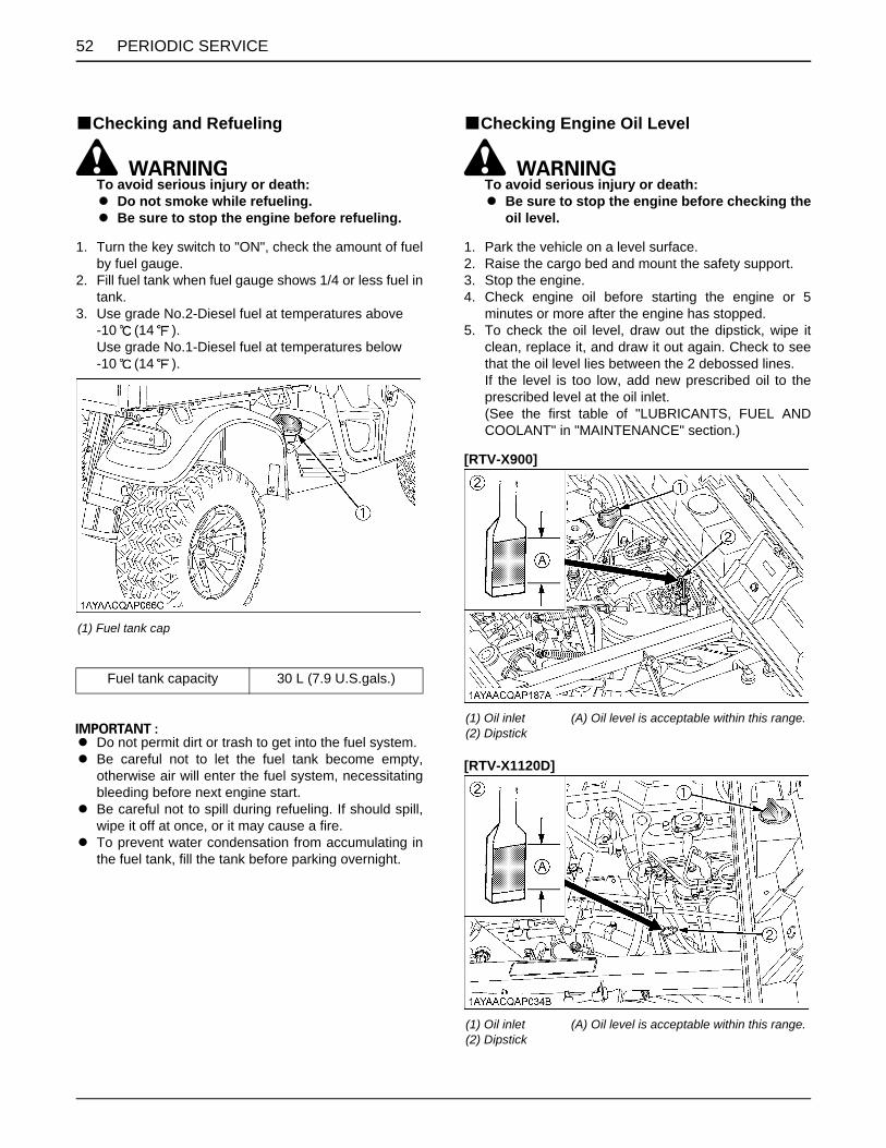
PERIODIC SERVICE52
BChecking and Refueling
To avoid serious injury or death:A Do not smoke while refueling.A Be sure to stop the engine before refueling.
1. Turn the key switch to "ON", check the amount of fuelby fuel gauge.
2. Fill fuel tank when fuel gauge shows 1/4 or less fuel intank.
3. Use grade No.2-Diesel fuel at temperatures above-10 (14 ).Use grade No.1-Diesel fuel at temperatures below-10 (14 ).
A Do not permit dirt or trash to get into the fuel system.A Be careful not to let the fuel tank become empty,
otherwise air will enter the fuel system, necessitatingbleeding before next engine start.
A Be careful not to spill during refueling. If should spill,wipe it off at once, or it may cause a fire.
A To prevent water condensation from accumulating inthe fuel tank, fill the tank before parking overnight.
BChecking Engine Oil Level
To avoid serious injury or death:A Be sure to stop the engine before checking the
oil level.
1. Park the vehicle on a level surface.2. Raise the cargo bed and mount the safety support.3. Stop the engine.4. Check engine oil before starting the engine or 5
minutes or more after the engine has stopped.5. To check the oil level, draw out the dipstick, wipe it
clean, replace it, and draw it out again. Check to seethat the oil level lies between the 2 debossed lines.If the level is too low, add new prescribed oil to theprescribed level at the oil inlet.(See the first table of "LUBRICANTS, FUEL ANDCOOLANT" in "MAINTENANCE" section.)
[RTV-X900]
[RTV-X1120D]
(1) Fuel tank cap
Fuel tank capacity 30 L (7.9 U.S.gals.)
(1) Oil inlet(2) Dipstick
(A) Oil level is acceptable within this range.
(1) Oil inlet(2) Dipstick
(A) Oil level is acceptable within this range.

53PERIODIC SERVICE
A When using an oil of different maker or viscosity fromthe previous one, remove all of the old oil.Never mix 2 different types of oil.
A If oil level is low, do not run engine.
BChecking Transmission Fluid Level1. Park the vehicle on a level surface.2. Raise the cargo bed and mount the safety support.3. Stop the engine.4. To check the oil level, draw out the dipstick, wipe it
clean, replace it, and draw it out again. Check to seethat the oil level lies within the cross hatched area.If the level is too low, add new prescribed oil to theprescribed level at the oil inlet.(See the first table of "LUBRICANTS, FUEL ANDCOOLANT" in "MAINTENANCE" section.)
A If oil level is low, do not run engine.
BChecking Hydraulic Oil Tank Level1. Park the vehicle on a level surface.2. Stop the engine.3. Open the seat and remove the utility box.4. Remove the rubber cap.5. To check the oil level, remove the dipstick, wipe it
clean, screw it into filling hole and remove dipstickagain.If the level is too low, add new prescribed oil to theprescribed level at the oil inlet.(See the first table of "LUBRICANTS, FUEL ANDCOOLANT" in "MAINTENANCE" section.)
A If oil level is low, do not run engine.
(1) Oil inlet(2) Dipstick
(A) Oil level is acceptable within this range.
(1) Filling plug with dipstick (A) Oil level is acceptable within this range
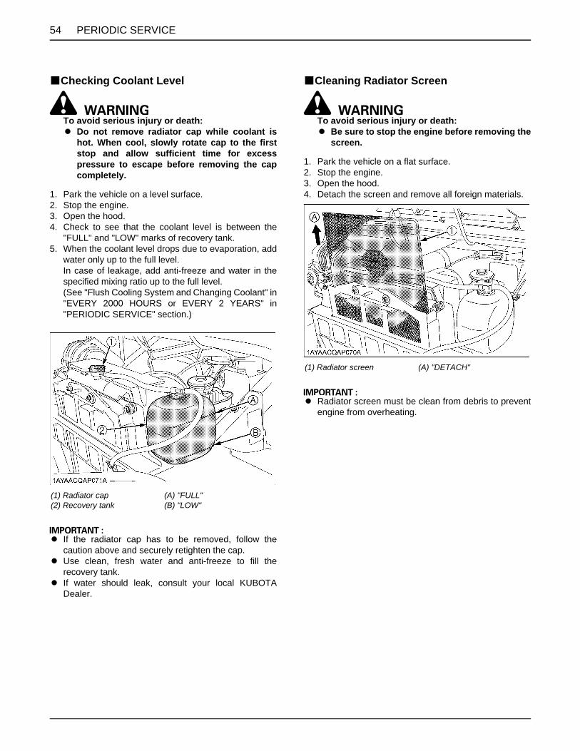
PERIODIC SERVICE54
BChecking Coolant Level
To avoid serious injury or death:A Do not remove radiator cap while coolant is
hot. When cool, slowly rotate cap to the firststop and allow sufficient time for excesspressure to escape before removing the capcompletely.
1. Park the vehicle on a level surface.2. Stop the engine.3. Open the hood.4. Check to see that the coolant level is between the
"FULL" and "LOW" marks of recovery tank.5. When the coolant level drops due to evaporation, add
water only up to the full level.In case of leakage, add anti-freeze and water in thespecified mixing ratio up to the full level.(See "Flush Cooling System and Changing Coolant" in"EVERY 2000 HOURS or EVERY 2 YEARS" in"PERIODIC SERVICE" section.)
A If the radiator cap has to be removed, follow thecaution above and securely retighten the cap.
A Use clean, fresh water and anti-freeze to fill therecovery tank.
A If water should leak, consult your local KUBOTADealer.
BCleaning Radiator Screen
To avoid serious injury or death:A Be sure to stop the engine before removing the
screen.
1. Park the vehicle on a flat surface.2. Stop the engine.3. Open the hood.4. Detach the screen and remove all foreign materials.
A Radiator screen must be clean from debris to preventengine from overheating.
(1) Radiator cap(2) Recovery tank
(A) "FULL"(B) "LOW"
(1) Radiator screen (A) "DETACH"

55PERIODIC SERVICE
BCleaning Oil Cooler Net
To avoid serious injury or death:A Allow oil cooler or oil line parts to cool down
sufficiently, they can be hot and can causeinjury.
1. Park the vehicle on a flat surface.2. Stop the engine.3. Open the seats and remove the utility box and
maintenance cover.4. Detach the oil cooler net and remove all trash.
BChecking Brake Fluid Level
To avoid serious injury or death:A Never operate the vehicle, if the brake fluid is
below the "MIN" mark.A Use only KUBOTA DOT3 GENUINE BRAKE
FLUID from a sealed container. Using othertype of oil ruins synthetic resin or rubberinstalled in brake system components, andmay cause brake failure.
A Avoid contamination of the brake fluid.Thoroughly clean area around the filler capbefore removing. Do not open the brake fluidreservoir cap unless absolutely necessary.
A Use extreme care when filling the reservoir. Ifbrake fluid is spilled on the power steeringhose, wash off with water immediately. Brakefluid quickly ruins synthetic resin or rubberhoses.
1. Park the vehicle on a level surface.2. Open the hood.3. Check to see that the brake fluid level is between the
"MAX" and "MIN" marks.4. If it is below the "MIN" mark, add brake fluid to the
"MAX" mark.
(1) Oil cooler net (A) "DETACH"
(1) Oil tank (A) "MAX"(B) "MIN"

PERIODIC SERVICE56
BChecking Brake Pedal
To avoid serious injury or death:A Stop the engine and chock the wheels before
checking brake pedal.
1. Inspect the brake pedals for free travel, and smoothoperation.
2. Adjust if incorrect measurement is found: (See"Checking Brake Pedal" in "EVERY 200 HOURS" in"PERIODIC SERVICE" section.)
BChecking Parking BrakePull the parking brake lever to apply the brakes. With thekey switch at "ON" position, the parking brake indicator onthe instrument panel lights up. To release the brakes,push in the button at the side of the parking brake leverand tilt the lever forward.
A Make sure the parking brake warning lamp on theEasy Checker(TM) goes off when parking brake leveris forward.
BChecking Easy Checker(TM)1. Inspect the instrument panel for broken Easy
Checker(TM) lamps.2. Consult your local KUBOTA Dealer if broken.
BChecking Head Light, Turn Signal Light (if equipped) etc.
1. Inspect the lights for broken bulbs and lenses.2. Replace if broken.
BChecking Seat Belt and ROPS1. Always check condition of the seat belts before
operating the vehicle.2. Replace if damaged.
(1) Brake pedal (A) "FREE TRAVEL"(B) "PEDAL STROKE"
(1) Parking brake lever(2) Release button
(A) "PULL"(B) "RELEASE"

57PERIODIC SERVICE
BChecking Joint Boot1. Check to see if the joint boots are not damaged.2. If the joint boots are cut, cracked or show signs of
deterioration, consult your local KUBOTA Dealer.
[Front]
(1) Joint boot(2) Front drive shaft(3) Tie rod
(1) Joint boot(2) Front drive shaft
(1) Joint boot(2) Rear drive shaft
(1) Joint boot (A) Rear stabilizer
(1) Joint boot(2) Drive shaft
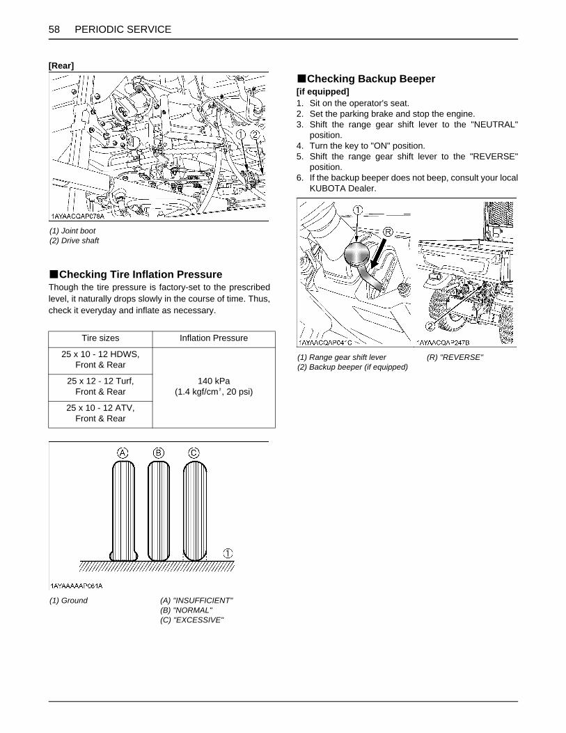
PERIODIC SERVICE58
[Rear]
BChecking Tire Inflation PressureThough the tire pressure is factory-set to the prescribedlevel, it naturally drops slowly in the course of time. Thus,check it everyday and inflate as necessary.
BChecking Backup Beeper[if equipped]1. Sit on the operator's seat.2. Set the parking brake and stop the engine.3. Shift the range gear shift lever to the "NEUTRAL"
position.4. Turn the key to "ON" position.5. Shift the range gear shift lever to the "REVERSE"
position.6. If the backup beeper does not beep, consult your local
KUBOTA Dealer.
(1) Joint boot(2) Drive shaft
Tire sizes Inflation Pressure
25 x 10 - 12 HDWS, Front & Rear
140 kPa(1.4 kgf/cm , 20 psi)
25 x 12 - 12 Turf,Front & Rear
25 x 10 - 12 ATV,Front & Rear
(1) Ground (A) "INSUFFICIENT"(B) "NORMAL"(C) "EXCESSIVE"
(1) Range gear shift lever(2) Backup beeper (if equipped)
(R) "REVERSE"

59PERIODIC SERVICE
EVERY 50 HOURSBGreasingApply a small amount of multi-purpose grease to thefollowing points every 50 hours: If you operated thevehicle in extremely wet and muddy conditions, lubricategrease fittings more often.
(1) Parking brake lever (spray type grease)
(1) Battery terminals
(1) Cargo lift cylinder pivot (Grease fitting)(2) Cargo bed pivot (spray type grease)
(1) VHT link (Grease fitting)(2) VHT link (spray type grease)(3) Valve lever link (spray type grease)(4) 4WD lever link (spray type grease)
(1) Range gear shift link (spray type grease) (A) Left rear tire
(1) Unload link (spray type grease)

PERIODIC SERVICE60
BChecking Engine Start System
To avoid serious injury or death:A Do not allow anyone near the vehicle while
testing.A If the vehicle does not pass the test do not
operate the vehicle.
C Preparation before testing.1. Place all control levers in the "NEUTRAL" position.2. Set the parking brake and stop the engine.
C Test: Range gear shift lever safety switch1. Sit on the operator's seat.2. Shift the range gear shift lever to H position.3. Return the Speed control pedal to the "NEUTRAL"
position.4. Shift the hydraulic lift cylinder lever to the "NEUTRAL"
position.5. Turn the key to "START" position.6. The engine must not crank.7. Repeat the step 2 to 6 with the range gear shift lever
at "L" and "R" each position.8. If it cranks, consult your local KUBOTA Dealer for
service.
(1) Differential lock pedal (spray type grease)
(1) Front A-ARM (Grease fitting)
(1) Rear A-ARM (Grease fitting)(2) Parking brake link (spray type grease)
(A) Left rear tire
(1) Range gear shift lever(2) Speed control pedal

61PERIODIC SERVICE
EVERY 100 HOURSBChecking VHT Neutral Spring1. Park the vehicle on a flat place.2. Set the parking brake.3. Shift the range gear shift lever to the "NEUTRAL"
position.4. Lock the hydraulic lift cylinder lever to the "NEUTRAL"
position with restricting plate.5. Start the engine.6. Make sure that the rotation speed of the engine
returns to the idling rotation immediately when takingthe foot off the pedal, after depressing the speedcontrol pedal several times. If the above does notoccur immediately, consult your local KUBOTA dealerfor this service.
BChecking VHT Pressure Release
To avoid serious injury or death:A Do not touch muffler or exhaust pipes while
they are hot; severe burns could result.
1. Park the vehicle on a level surface and set the parkingbrake.
2. Start the engine and shut it off quickly.3. Check the points as shown in the figures below.4. If the result corresponds to either of the following (a) or
(b), consult your local KUBOTA Dealer.(a) No clearance between rod and link.(b) The length of the rod is appeared 21.5 mm and over.
(1) Hydraulic lift cylinder lever
(1) Unload link(2) Unload valve rod
(L) 21.5 mm and over(P) The link is contact with the rod.

PERIODIC SERVICE62
BChecking Wheel Fastener Torque
To avoid serious injury or death:A Never operate vehicle with a loose wheel bolts.A Any time bolts are loosened, retighten to the
specified torque.A Check all bolts frequently and keep them tight.
Check wheel bolts regularly especially when new. If theyare loose, tighten them as follows.
BCleaning Air Cleaner Primary Element1. Remove the air cleaner cover and primary element.2. Clean the primary element:
(1) When dry dust adheres to the element, blowcompressed air from the inside, turning theelement. Pressure of compressed air must beunder 205 kPa (2.1 kgf/cm , 30 psi).
(2) When carbon or oil adheres to the element,replace the element with new one even if it hasnot been used for 1 year.Do not blow material onto yourself. Wearappropriate protective gear when cleaningelement.
3. Replace the primary element:Once yearly or 1000 hours whichever comes first.
A Check to see if the evacuator valve is blocked withdust.
A Check the rubber seal. Replace if damaged.
A The air cleaner uses a dry element, never apply oil.A Do not run the engine with filter element removed.A Be sure to refit the cover with the arrow (on the rear of
cover) upright. If the cover is improperly fitted,evacuator valve will not function and dust will adhereto the element.
A Do not touch the secondary element except in caseswhere replacing is required.
C Evacuator ValveOpen the evacuator valve once a week under ordinaryconditions - or daily when used in a dusty place - to get ridof large particles of dust and dirt.
(1) Tightening torque (bolts and nuts) Aluminum wheel: 90 to 110 N-m (9.2 to 11.2 kgf-m) (66.4 to 81.1 lbf-ft) Steel wheel: 108 to 130 N-m (11.1 to 13.2 kgf-m) (79.7 to 95.8 lbf-ft)
(1) Secondary (safety) element(2) Primary element(3) Rubber seal(4) Evacuator valve(5) Cover

63PERIODIC SERVICE
BAdjusting Alternator Belt Tension
To avoid serious injury or death:A Be sure to stop the engine before checking belt
tension.
1. Park the vehicle on a flat surface. Stop the engine.2. Open the seat and remove the maintenance cover.3. Apply moderate thumb pressure to the middle of the
belt span between the fan drive pulley and alternatorpulley.
4. If tension is incorrect, loosen the alternator mountingbolts and, using a lever placed between the alternatorand the engine block, pull the alternator out until thedeflection of the belt falls within acceptable limits.
5. Replace alternator belt if it is damaged.
BChecking Fuel Filter
To avoid serious injury or death:A Be sure to stop the engine and remove the key
when attempting to make the following checksand changes.
A Never fail to check the fuel lines periodically.The fuel lines are subject to wear and aging.Fuel may leak out onto the running engine,causing a fire.
Fuel lines should be checked every 1 year.1. Park the vehicle on a flat surface, raise the cargo bed,
mount the safety support and shut off the engine.2. The fuel line is made of rubber and ages regardless of
service period.3. If the fuel line and clamps are found to be damaged or
deteriorated, replace them.4. Check fuel filter, if it is clogged by debris or
contaminated with water, replace it.
A When the fuel line is disconnected for maintenance orrepair, close both ends of the fuel line with a piece ofclean cloth or paper to prevent dust and dirt fromentering. In addition, particular care must be taken notto admit dust and dirt into the fuel pump. Entrance ofeven a small amount of dust or dirt cause prematurewear and malfunction of the fuel pump and injectorcomponents.
Proper alternator belt
tension
A deflection of between 7 to 9 mm (0.28 to 0.34 in.) when the belt is pressed in the middle of the span.
(1) Bolt (A) Check the belt tension(B) To tighten
(1) Fuel filter(2) Fuel line(3) Pipe clamp

PERIODIC SERVICE64
[RTV-X900]
[RTV-X1120D]
BChecking Battery Condition
To avoid the possibility of battery explosion:For the refillable type battery, follow theinstructions below.A Do not use or charge the refillable type battery
if the fluid level is below the LOWER (lower limitlevel) mark. Otherwise, the battery componentparts may prematurely deteriorate, which mayshorten the battery's service life or cause anexplosion. Check the fluid level regularly andadd distilled water as required so that the fluidlevel is between the UPPER and LOWER levels.
To avoid serious injury or death:A When the battery is being activated, hydrogen
and oxygen gases in the battery are extremelyexplosive. Keep open sparks and flames awayfrom the battery at all times, especially whencharging the battery.
To avoid serious injury or death:A Batteries, battery posts, terminals and related
accessories contain lead and lead compounds,and other chemicals known to the State ofCalifornia to cause cancer and birth defects orother reproductive harm. WASH HANDSAFTER HANDLING.
A Never remove the battery cap while the engineis running.
A Keep electrolyte away from eyes, hands andclothes. If you are spattered with it, wash itaway completely with water immediately andget medical attention.
A Keep open sparks and flames away from thebattery at all times. Hydrogen gas mixed withoxygen becomes very explosive.
A Wear eye protection and rubber gloves whenworking around battery.
(1) Fuel line(2) Pipe clamp
(1) Fuel pump(2) Fuel line(3) Pipe clamp
The factory-installed battery is non-refillable type.If the battery is weak, charge the battery or replace it with new one.

65PERIODIC SERVICE
A Mishandling the battery shortens the service life andadds to maintenance costs.The original battery is maintenance free, but needssome servicing.If the battery is weak, the engine will be difficult to startand the lights will be dim. It is important to check thebattery periodically.
A When exchanging an old battery for a new one, usebattery of equal specification in table below.
(For non-accessible maintenance-free type batteries.)Maintenance-free, non-accessible batteries are designedto eliminate the need to add water. Yet the volume ofelectrolyte above plates may eventually become depleteddue to abnormal conditions such as high heat or improperregulator setting. Use a voltmeter to check the state ofcharge. (See reference chart below to determine ifcharging is necessary.)
C Battery Charging
To avoid serious injury or death:A When the battery is being activated, hydrogen
and oxygen gases in the battery are extremelyexplosive. Keep open sparks and flames awayfrom the battery at all times, especially whencharging the battery.
To avoid serious injury or death:A When disconnecting the cable from the battery,
start with the negative terminal first. Whenconnecting the cable to the battery, start withthe positive terminal first.
A Never check battery charge by placing a metalobject across the posts.Use a voltmeter or hydrometer.
1. Park the vehicle on a flat surface.2. Stop the engine.3. Remove the battery cover.4. To slow charge the battery, connect the battery
positive terminal to the charger positive terminal andthe negative to the negative, then recharge in thestandard fashion.
5. A boost charge is only for emergencies. It will partiallycharge the battery at a high rate and in a short time. When using a boost-charged battery, it is necessary torecharge the battery as early as possible. Failure to do this will shorten the battery's service life.
6. When exchanging an old battery for a new one, usebattery of equal specification shown in table 1.
C Direction for Storage1. When storing the vehicle for a long period, remove the
battery from vehicle, adjust the electrolyte to theproper level (refillable type only) and store in a dryplace out of direct sunlight.
2. The battery self-discharges while it is stored.Recharge it once every 3 months in hot seasons andonce every 6 months in cold seasons.
Model Battery Type
Volts (V)
Reserve Capacity
(min)
Cold Cranking
Amps
Capacity at 20 hrs (A. H.)
Normal Charging Rate (A)
RTV-X900 26R-560 12 86 560 - 8.6
RTV-X1120D 24R-670 12 115 670 66 11.5
Battery voltage Reference state of charge
12.6 100% (Full charge)
12.4 75%
12.2 50%
12.0 25%
11.8 0%
(1) Battery

PERIODIC SERVICE66
BAdjusting Toe-in
1. Park vehicle on a flat place.2. Turn steering wheel so front wheels are in the straight
ahead position.3. Lock the park brake and stop the engine.4. Measure distance between tire beads at front of tire, at
hub height.5. Measure distance between tire beads at rear of tire, at
hub height.6. Front distance should be shorter than rear distance. If
not, adjust tie rod length.
C Adjusting procedures1. Loosen the lock nut and turn the tie rod to adjust the
rod length until the proper toe-in measurement isobtained.
2. Retighten the lock nut.
A Keep the length of the left and right tie-rod equal.
A Tightening torque (LOCK NUT):74 to 84 N-m(7.6 to 8.5 kgf-m)(55 to 61 lbf-ft)
Proper toe-in 5 to 15 mm (0.2 to 0.59 in.)
(A) Wheel - to - wheel distance at rear(B) Wheel - to - wheel distance at front(C) "FRONT"
(1) Lock nuts(2) Tie-rod

67PERIODIC SERVICE
BCleaning Muffler [For Swirl Type Spark Arrester]
To avoid serious injury or death:A Before touching any part of an exhaust system,
be absolutely sure that it has sufficient time tocool !
A Always wear safety goggles and a (face) mask.A The particulate matter contained in the muffler
contains chemicals that are harmful to people,animals and marine life.
A If you are unable to do this work, have it doneby your KUBOTA Dealer.
C Cleaning spark arrester of mufflerThis swirl type spark arrester was examined, tested, andqualified in accordance with the USDA Forest ServiceStandard 5100-1c, "Spark Arresters for InternalCombustion Engines".
Maintenance & cleanout procedure:The swirl type spark arrester should be cleaned andinspected after every 100 hours of use.1. Set vehicle in an open area away from combustible
materials and on flat surface.2. Apply the parking brake and shift range gear shift lever
into the "NEUTRAL" position.3. Remove the drain plug located on the bottom of the
muffler body.4. Start engine and raise and lower engine revolution
while tapping on the muffler with a rubber mallet untilthe carbon particles are purged from the muffler.
5. Stop the engine.6. Reinstall the drain plug.
A Visually check the muffler for cracks or holes in thebody, weldment or pipes at regular intervals.
A Replace the entire muffler if it is damaged.A Do not operate the vehicle with a damaged muffler.
(1) Muffler(2) Drain plug

PERIODIC SERVICE68
EVERY 200 HOURSBAdjusting Parking Brake
C Adjusting procedure1. Park the vehicle on a flat surface.2. Stop the engine.3. Jack up the rear wheels.4. Remove the left rear tire.5. Remove the mud guard of rubber.6. Release the parking brake.7. Loosen the lock nuts.8. Adjust the cable wire length.9. Tighten the lock nuts securely.10. Install the mud guard.11. Install the left rear tire.
Proper parking brake lever free play range 1 notch
(1) Parking brake lever
(A) Mud guard(B) Push rivet
(1) Lock nut(2) Cable wire

69PERIODIC SERVICE
BReplacing Engine Oil Filter
To avoid serious injury or death:A Be sure to stop the engine before changing the
oil filter.A Allow engine to cool down sufficiently, oil can
be hot and can burn.
1. Park the vehicle on a flat surface.2. Stop the engine.3. Remove the rear skid plate.4. Remove the oil filter.5. Put a film of clean engine oil on the rubber seal of the
new filter.6. Tighten the filter quickly until it contacts the mounting
surface.Tighten the filter by hand an additional 1/2 turn only.
7. After the new filter has been replaced, the engine oilnormally decreases a little. Make sure that the engineoil does not leak through the seal and be sure to checkthe oil level on the dipstick. Then, replenish the engineoil up to the prescribed level.
8. Properly dispose of used filter.
A To prevent serious damage to the engine, use only aKUBOTA genuine filter.
BChanging Engine Oil
To avoid serious injury or death:A Be sure to stop the engine before changing the
oil.A Allow engine to cool down sufficiently, oil can
be hot and can burn.
1. Park the vehicle on a level surface.2. Raise the cargo bed and mount the safety support. 3. Stop the engine.4. Remove the rear skid plate.5. To drain the used oil, remove the drain plug at the
bottom of the engine and completely drain the oil intoan oil pan.All the used oil can be drained out easily when theengine is still warm.
6. After draining, reinstall the drain plug.7. Fill with the new prescribed oil up to the upper line on
the dipstick.(See the first table of "LUBRICANTS, FUEL ANDCOOLANT" in "MAINTENANCE" section.)
8. Properly dispose of used filter.
[RTV-X900]
(1) Engine oil filter (A) Battery
Oil capacity
RTV-X900
[Filter exchanged]3.1 L (3.3 U.S.qts.)
[Filter non-exchanged]2.7 L (2.9 U.S.qts.)
RTV-X1120D
[Filter exchanged]4.1 L (4.3 U.S.qts.)
[Filter non-exchanged]3.8 L (4.0 U.S.qts.)
(1) Oil inlet(2) Dipstick
(A) Oil level is acceptable within this range.

PERIODIC SERVICE70
[RTV-X1120D]BReplacing Transmission Oil Filter [VHT]
To avoid serious injury or death:A Be sure to stop the engine before changing the
oil filter.A Allow engine to cool down sufficiently, oil can
be hot and can burn.
1. Park the vehicle on a flat surface.2. Remove the rear guard.3. Remove the oil filter.4. Put a film of clean transmission oil on the rubber seal
of the new filter.5. Quickly tighten the filter by hand until it contacts the
mounting surface, then, with a filter wrench, tighten itan additional 1/2 turn only.
6. After the new filter has been replaced, fill the hydraulictank oil up to the upper notch on the dipstick.
7. After running the engine for a few minutes, stop theengine and check the oil level again, add oil to theprescribed level.
8. Make sure that the transmission fluid doesn't leak pastthe seal on the filters.
A To prevent serious damage to the transmission, useonly a KUBOTA genuine filter.
(1) Oil inlet(2) Dipstick
(A) Oil level is acceptable within this range.
(1) Rear skid plate
(1) Drain plug
(1) Transmission oil filter (VHT) (Yellow color)(2) Rear guard

71PERIODIC SERVICE
BReplacing Transmission Oil Filter [SUCTION]
To avoid serious injury or death:A Be sure to stop the engine before changing the
oil filter.A Allow engine to cool down sufficiently, oil can
be hot and can burn.
1. Park the vehicle on a flat surface.2. Remove the rear guard.3. Remove the oil filter and old seal.4. Put a film of clean transmission oil on the rubber seal
of the new filter.5. Quickly tighten the filter by hand until it contacts the
mounting surface, then, with a filter wrench, tighten itan additional 1/2 turn only.
6. After the new filter has been replaced, fill the hydraulictank oil up to the upper notch on the dipstick.
7. After running the engine for a few minutes, stop theengine and check the oil level again, add oil to theprescribed level.
8. Make sure that the transmission fluid doesn't leak pastthe seal on the filters.
9. Install the rear guard, and the hose guard.
A To prevent serious damage to the transmission, useonly a KUBOTA genuine filter.
BChanging Hydraulic Tank Oil
To avoid serious injury or death:A Be sure to stop the engine before changing the
oil.A Allow engine to cool down sufficiently, oil can
be hot and can burn.
1. Park the vehicle on a level surface.2. Open the seat and remove the utility box.3. Remove the rubber cap.4. To drain the used oil, remove the drain plug and filling
plug and drain the oil completely into the oil pan.5. After draining, reinstall the drain plug.6. Fill with new prescribed oil up to the upper line on the
dipstick. (See the following figure.)(See the first table of "LUBRICANTS, FUEL ANDCOOLANT" in "MAINTENANCE" section.)How to check:Wipe dipstick clean with a rag and screw it into fillinghole. Remove dipstick again to see if the oil level isbetween the upper and lower line.
7. After filling, reinstall the filling plug.8. Properly dispose of used filter.
(1) Transmission oil filter (Suction) (Black color)(2) Rear guard
Oil Capacity 18.0 L (19.0 U.S.qts.)
(1) Drain plug

PERIODIC SERVICE72
BChecking Brake Pedal
To avoid serious injury or death:A Stop the engine and chock the wheels before
checking brake pedal.A If movement is outside of the specifications,
contact your local KUBOTA Dealer foradjusting the brake.
C Checking the brake pedal free travel
1. Release the parking brake.2. Slightly depress the brake pedal and measure free
travel at the top of the pedal stroke.3. If brake pedal free travel is outside of the
specifications, contact your local KUBOTA Dealer foradjusting the brake.
C Checking the brake pedal stroke
1. Release the parking brake.2. Step on the pedal and measure the pedal stroke.3. If brake pedal stroke is outside of the specifications,
contact your local KUBOTA Dealer for adjusting thebrake.
(1) Filling plug with dipstick (A) Oil level is acceptable within this range
Proper brake pedalfree travel
8 to 18 mm (0.3 to 0.7 in.)on the pedal
Pedal stroke Less than 150 mm (5.9 in.)on the pedal
(1) Brake pedal (A) "FREE TRAVEL"(B) "PEDAL STROKE"

73PERIODIC SERVICE
BChecking Front Brake Case1. Remove the drain plugs and the air-bleeding hole
plugs.2. Check the brake case for brake fluid leak.3. If there is brake fluid leak, consult your local KUBOTA
Dealer for this service.
BChecking Brake Light Switch1. Park the vehicle on a flat surface.2. Step on the brake pedal to check if the brake light
comes on.3. If it does not, check the bulb or brake light switch.
(1) Drain plug(2) Allen key(3) Air-bleeding hole plug
(1) Brake light switch

PERIODIC SERVICE74
EVERY 300 HOURSBChecking Tire1. Check to see if tires are not damaged.2. If the tires are cracked, bulged, or cut, or they are worn
out, replace or repair them at once.
C Tire Tread DepthAlways replace the tires when the tread depth is worn tominimum allowable.
EVERY 400 HOURSBChanging Front Knuckle Case Oil1. Park the vehicle on a firm, flat and level surface.2. Remove the tire.3. To drain the used oil, remove the drain and filling plugs
at the left hand knuckle case and drain the oilcompletely into the oil pan.
4. After draining, reinstall the drain plug.5. Fill with the new prescribed oil up to the filling port
level.(See the first table of "LUBRICANTS, FUEL ANDCOOLANT" in "MAINTENANCE" section.)
6. After filling, reinstall the filling plug.7. Use the same procedure to change the right hand
knuckle case oil.
8. Properly dispose of used oil.
(A) 3 mm (0.12 in.)
Oil capacity (one side) Ref. 0.25 L (0.26 U.S.qts.)
(1) Drain plug(2) Filling plug

75PERIODIC SERVICE
BChanging Transmission Fluid
To avoid serious injury or death:A Be sure to stop the engine before changing the
oil.A Allow engine to cool down sufficiently, oil can
be hot and can burn.
1. Park the vehicle on a level surface. 2. Raise the cargo bed and mount the safety support.3. To drain the used oil, remove the drain plug at the
bottom of the transmission case and drain the oilcompletely into the oil pan.
4. After draining, reinstall the drain plug.5. Fill with the new prescribed oil up to the upper cross
hatched area on the dipstick.(See the first table of "LUBRICANTS, FUEL ANDCOOLANT" in "MAINTENANCE" section.)
6. After running the engine for a few minutes, stop theengine and check the oil level again; add oil toprescribed level.
7. Properly dispose of used oil.
C Cleaning Magnet PlugRemove the magnet plug and clean off metal filings.
A Do not operate the vehicle immediately after changingthe transmission fluid.Run the engine at medium speed for a few minutes toprevent damage to the transmission.Oil Capacity 7.0 L (1.8 U.S.gals.)
(1) Oil inlet(2) Dipstick
(A) Oil level is acceptable within this range.
(1) Drain plug(2) Magnet plug

PERIODIC SERVICE76
BChanging Front Axle Case Oil1. Park the vehicle on a level surface.2. Turn over the rubber sheet.3. To drain the used oil, remove the drain plug and the
filling plug at the front axle case and drain the oilcompletely into the oil pan.
4. After draining, reinstall the drain plug.5. Fill with the new prescribed oil up to the upper line on
the dipstick.(See the first table of "LUBRICANTS, FUEL ANDCOOLANT" in "MAINTENANCE" section.)
6. After filling, reinstall the filling plug.7. Properly dispose of used oil.
BReplacing Fuel FilterConsult your local KUBOTA Dealer for this service.
EVERY 800 HOURSBAdjusting Engine Valve ClearanceConsult your local KUBOTA Dealer for this service.
EVERY 1000 HOURS or EVERY 1 YEARBReplacing Air Cleaner Primary Element
and Secondary Element(See "Cleaning Air Cleaner Primary Element" in "EVERY100 HOURS" in "PERIODIC SERVICE" section.)
EVERY 1500 HOURSBChecking Fuel Injection Nozzle Injection
PressureConsult your local KUBOTA Dealer for this service.
EVERY 2000 HOURS or EVERY 2 YEARSBe sure to do the following service once every 2000 hoursor every 2 years whichever comes faster.
BFlushing Cooling System and Changing Coolant
To avoid serious injury or death:A Do not remove the radiator cap while coolant is
hot. When cool, slowly rotate cap to the firststop and allow sufficient time for excesspressure to escape before removing the capcompletely.
1. Stop the engine and let cool down.2. Open the hood.3. To drain the coolant, open the radiator drain plug and
remove radiator cap and engine coolant breather. Theradiator cap must be removed to completely drain thecoolant.
4. After all coolant is drained, close the drain plug.5. Fill with clean water and cooling system cleaner.6. Follow directions of the cleaner instruction.7. After flushing, fill with clean distilled water and anti-
freeze until the coolant level is just below the radiatorcap.Install the radiator cap securely.
8. Fill with fresh distilled water up to the "FULL" mark onthe recovery tank.
9. Close the engine coolant breather.10.Start and operate the engine for few minutes.11.Stop the engine and let cool.12.Check coolant level of recovery tank and add coolant
if necessary.
Oil capacity 0.6 L (0.6 U.S.qts.)
(1) Drain plug(2) Filling plug with dipstick
(A) Oil level is acceptable within this range
Coolant capacity 6.1 L (6.4 U.S.qts.)

77PERIODIC SERVICE
A Do not start engine without coolant.A Do not remove the cap on the radiator.A Use clean, fresh distilled water and anti-freeze to fill
the radiator and recovery tank.
A When the anti-freeze is mixed with distilled water, theanti-freeze mixing ratio is 50%.
A Securely tighten radiator cap. If the cap is loose orimproperly fitted, water may leak out and the enginecould overheat.
A Make sure that the engine coolant breather is closed,after filling the coolant.
BAnti-Freeze
To avoid serious injury or death:A When using anti-freeze, put on some protection
such as rubber gloves. (Anti-freeze containspoison.)
A If it is swallowed, seek immediate medical help.Do NOT make a person throw up unless told todo so by poison control or a health careprofessional. Use standard first aid and CPRfor signs of shock or cardiac arrest. Call yourlocal Poison Control Center or your localemergency number for further assistance.
A When anti-freeze comes in contact with theskin or clothing, wash it off immediately.
A Do not mix different types of Anti-freeze.The mixture can produce chemical reactioncausing harmful substances.
A Anti-freeze is extremely flammable andexplosive under certain conditions. Keep fireand children away from anti-freeze.
A When draining fluids from the engine, placesome container underneath the engine body.
A Do not pour waste onto the ground, down adrain, or into any water source.
A Also, observe the relevant environmentalprotection regulations when disposing of anti-freeze.
Always use a 50/50 mix of long-life coolant and clean softwater in KUBOTA engines.Consult your local KUBOTA dealer concerning coolant forextreme conditions.1. Long-life coolant (hereafter LLC) comes in several
types. Use ethylene glycol (EG) type for this engine.2. Before employing LLC-mixed cooling water, fill the
radiator with fresh water and empty it again.Repeat this procedure 2 or 3 times to clean up theinside.
3. Mixing the LLCPremix 50% LLC with 50% clean soft water. Whenmixing, stir it up well, and then fill into the radiator.
4. The procedure for the mixing of water and anti-freezediffers according to the make of the anti-freeze and theambient temperature. Refer to SAE J1034 standard,more specifically also to SAE J814c.
(1) Drain plug(2) Front skid plate
(1) Radiator cap(2) Recovery tank
(A) "FULL"(B) "LOW"
(1) Engine coolant breather

PERIODIC SERVICE78
A When mixing the anti-freeze with water, the anti-freezemixing ratio is 50%.
* At 1.013 x 10 Pa (760 mmHg) pressure (atmospheric).
A higher boiling point is obtained by using a radiatorpressure cap which permits the development of pressurewithin the cooling system.
5. Adding the LLC(1) Add only water if the coolant level reduces in the
cooling system by evaporation.(2) If there is a mixture leak, add the LLC of the same
manufacturer and type in the mixing ratio 50%.
6. When the LLC is mixed, do not employ any radiatorcleaning agent. The LLC contains anti-corrosiveagent. If mixed with the cleaning agent, sludge maybuild up, adversely affecting the engine parts.
7. Kubota's genuine long-life coolant has a service life of2 years. Be sure to change the coolant every 2000hours or every 2 years whichever comes faster.
A The above data represent industry standards thatnecessitate a minimum glycol content in theconcentrated anti-freeze.
EVERY 3000 HOURSBChecking Injection PumpConsult your local KUBOTA Dealer for this service.
EVERY 1 YEARBChecking Fuel Lines(See "Checking Fuel Filter" in "EVERY 100 HOURS" in"PERIODIC SERVICE" section.)
BChecking Hydraulic Oil Line1. Check to see if the hoses and hose clamps are tight
and not damaged.2. If hoses and clamps are found to be worn or damaged,
replace or repair them at once.
[Only with hydraulic dump]
Vol %Anti-freeze
Freezing Point Boiling Point*
50 -37 -34 108 226
* Never add any long-life coolant of different manufacturer. (Different brands may have different additive components, and the engine may fail to perform as specified.)
(1) Hydraulic pump Control valve(2) HST Oil tank(3) Control valve Lift cylinder(4) Control valve Power steering unit(5) Oil tank HST
(1) Power steering unit Oil cooler(2) Oil cooler Oil tank
(A) Oil cooler

79PERIODIC SERVICE
BChecking Radiator Hose, Pipe and ClampPark the vehicle on a flat surface. Raise the cargo bed andmount the safety support. Check to see if radiator hoses are properly fixed.1. If hose clamps are loose or water leaks, tighten bands
securely.2. Replace hoses and tighten hose clamps securely, if
radiator hoses are swollen, hardened or cracked.Replace hoses and hose clamps if you checked and foundthat hoses are swollen, hardened or cracked.
[RTV-X1120D]
(1) Oil tank Hydraulic pump (A) Hydraulic pump
(1) Power steering hose (Power steering unit Oil cooler)(2) Power steering hose (Power steering unit Power steering cylinder)(3) Power steering hose (with hydraulic dump: Power steering unit Control valve, without hydraulic dump: Power steering unit Hydraulic pump)(A) Power steering unit (B) Power steering cylinder
(1) Radiator hose(2) Clamp band
(1) Radiator hose(2) Clamp band
(A) Battery
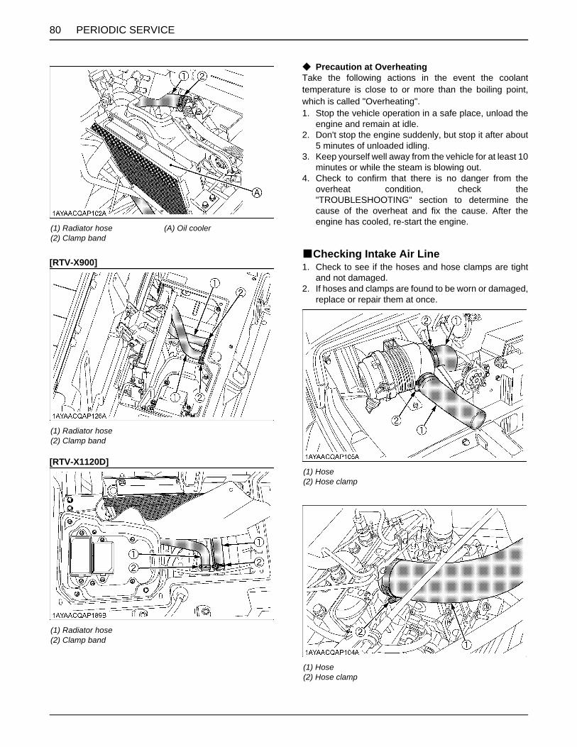
PERIODIC SERVICE80
[RTV-X900]
[RTV-X1120D]
C Precaution at OverheatingTake the following actions in the event the coolanttemperature is close to or more than the boiling point,which is called "Overheating".1. Stop the vehicle operation in a safe place, unload the
engine and remain at idle.2. Don't stop the engine suddenly, but stop it after about
5 minutes of unloaded idling.3. Keep yourself well away from the vehicle for at least 10
minutes or while the steam is blowing out.4. Check to confirm that there is no danger from the
overheat condition, check the"TROUBLESHOOTING" section to determine thecause of the overheat and fix the cause. After theengine has cooled, re-start the engine.
BChecking Intake Air Line1. Check to see if the hoses and hose clamps are tight
and not damaged.2. If hoses and clamps are found to be worn or damaged,
replace or repair them at once.
(1) Radiator hose(2) Clamp band
(A) Oil cooler
(1) Radiator hose(2) Clamp band
(1) Radiator hose(2) Clamp band
(1) Hose(2) Hose clamp
(1) Hose(2) Hose clamp

81PERIODIC SERVICE
BChecking Engine Breather Hose
To avoid serious injury or death:A Be sure to stop the engine and remove the key
before checking engine breather hose.
Check to see if engine breather hoses are properly fixedevery 1 year.1. Stop the engine and let cool down.2. If hose clamps are loose or water leaks, tighten bands
securely.3. Replace hoses and tighten hose clamps securely, if
engine breather hoses are swollen, hardened orcracked.
Replace hoses and hose clamps every 4 years or earlierif you checked and found that hoses are swollen,hardened or cracked.
BChecking Brake Hose and Pipe1. Check to see that brake hose and pipe are not swollen,
hardened or cracked.2. Check the brake hose and pipe joints for oil leaks.3. If there is any abnormality, consult your local KUBOTA
Dealer for this service.
(1) Hose(2) Hose clamp(3) Joint
(A) Hydraulic tank
(1) Brake pipe
(1) Brake hose(2) Breather hose
(1) Brake hose

PERIODIC SERVICE82
EVERY 2 YEARSBChanging Brake FluidConsult your local KUBOTA Dealer for this service.(See "Checking Brake Fluid Level" in "DAILY CHECK" in"PERIODIC SERVICE" section.)
EVERY 4 YEARSBReplacing Hydraulic Oil LineConsult your local KUBOTA Dealer for this service.
BReplacing Radiator Hose (Water pipes)Replace the hoses and clamps.(See "Checking Radiator Hose, Pipe and Clamp" in"EVERY 1 YEAR" in "PERIODIC SERVICE" section.)
BReplacing Fuel HoseConsult your local KUBOTA Dealer for this service.
BReplacing Engine Breather HoseConsult your local KUBOTA Dealer for this service.
BReplacing Brake Master Cylinder (Inner Parts)
Consult your local KUBOTA Dealer for this service.
BReplacing Front Brake SealConsult your local KUBOTA Dealer for this service.
BReplacing Rear Brake Cylinder SealConsult your local KUBOTA Dealer for this service.
BReplacing Intake Air LineConsult your local KUBOTA Dealer for this service.(See "Checking Intake Air Line" in "EVERY 1 YEAR" in"PERIODIC SERVICE" section.)
BReplacing Brake Hose and PipeConsult your local KUBOTA Dealer for this service.
(1) Brake pipe (A) Oil cooler
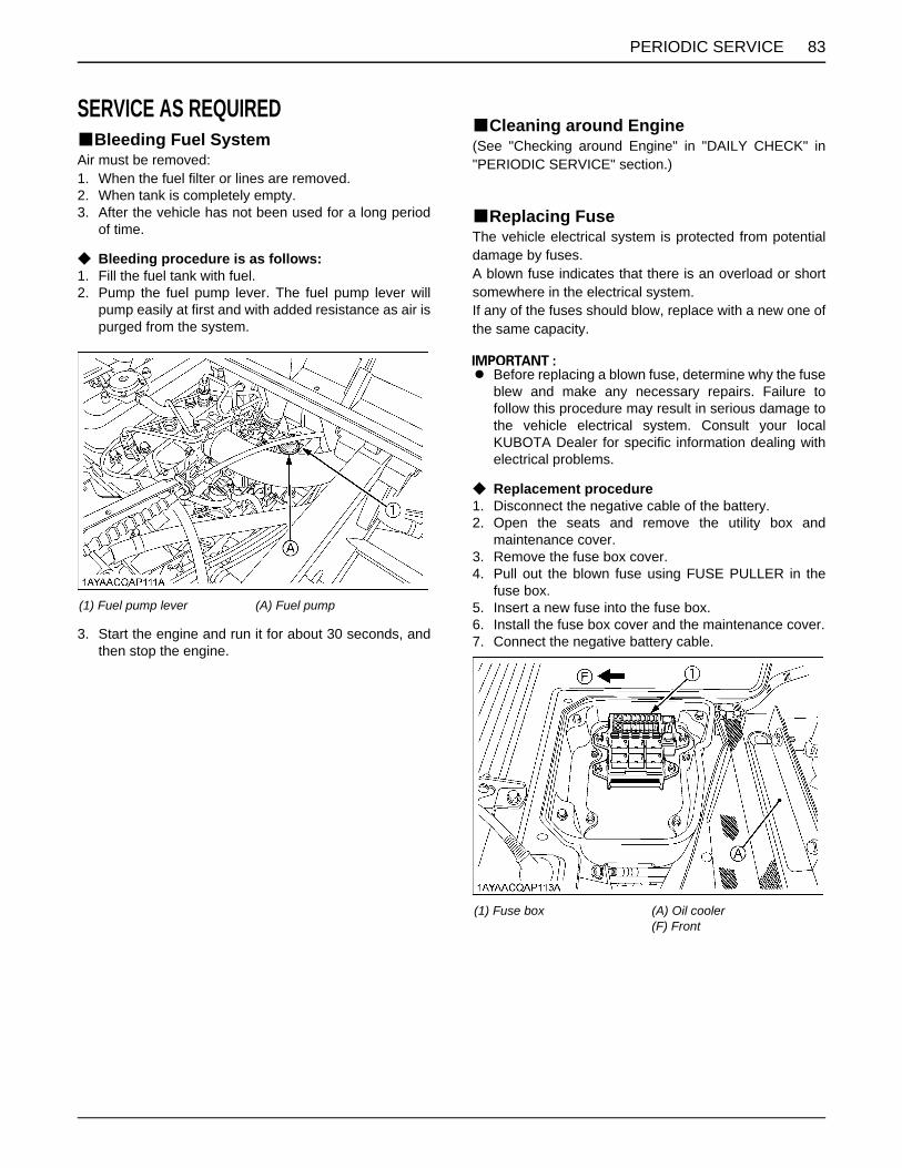
83PERIODIC SERVICE
SERVICE AS REQUIREDBBleeding Fuel SystemAir must be removed:1. When the fuel filter or lines are removed.2. When tank is completely empty.3. After the vehicle has not been used for a long period
of time.
C Bleeding procedure is as follows:1. Fill the fuel tank with fuel.2. Pump the fuel pump lever. The fuel pump lever will
pump easily at first and with added resistance as air ispurged from the system.
3. Start the engine and run it for about 30 seconds, andthen stop the engine.
BCleaning around Engine(See "Checking around Engine" in "DAILY CHECK" in"PERIODIC SERVICE" section.)
BReplacing FuseThe vehicle electrical system is protected from potentialdamage by fuses.A blown fuse indicates that there is an overload or shortsomewhere in the electrical system.If any of the fuses should blow, replace with a new one ofthe same capacity.
A Before replacing a blown fuse, determine why the fuseblew and make any necessary repairs. Failure tofollow this procedure may result in serious damage tothe vehicle electrical system. Consult your localKUBOTA Dealer for specific information dealing withelectrical problems.
C Replacement procedure1. Disconnect the negative cable of the battery.2. Open the seats and remove the utility box and
maintenance cover.3. Remove the fuse box cover.4. Pull out the blown fuse using FUSE PULLER in the
fuse box.5. Insert a new fuse into the fuse box.6. Install the fuse box cover and the maintenance cover.7. Connect the negative battery cable.
(1) Fuel pump lever (A) Fuel pump
(1) Fuse box (A) Oil cooler(F) Front

PERIODIC SERVICE84
(F) Front (20) Fuse puller (A) Fuse
[RTV-X900] Protected circuit
[RTV-X1120D] Protected circuit
Fuse No. Capacity (A) Protected circuit Fuse
No. Capacity (A) Protected circuit
1 5 Glow lamp 1 5 Glow lamp
2 5 Starter relay 2 5 Starter relay
3 10 Radiator fan relay 3 10 Radiator fan relay
4 10 AUX / B, Buzzer relay (OPT, LAMP) 4 10 AUX / B, Buzzer relay (OPT, LAMP)
5 5 Key stop timer 5 5 Solenoid
6 5 Meter (IGN) 6 5 Meter (IGN)
7 15 Beacon / Fog lamp 7 15 Beacon / Fog lamp
8 15 Head light blinker (F) 8 15 Head light blinker (F)
9 15 Blinker (R) brake lamp 9 15 Blinker (R) brake lamp
10 30 Radiator fan 10 30 Radiator fan
11 10 DC output 11 10 DC output
12 20 --- 12 20 ---
13 10 Horn 13 10 Horn
14 15 Work light 14 15 Work light
15 15 Key stop timer 15 30 Solenoid
16 5 Meter (BAT) 16 5 Meter (BAT)
17 30, 20, 15, 10, 5 Spare 17 30, 20, 15, 10, 5 Spare
18 Slow-blow fuse (60) Key switch 18 Slow-blow fuse
(60) Key switch
19 Slow-blow fuse (60) Alternator 19 Slow-blow fuse
(60) Alternator
20 - Fuse puller 20 - Fuse puller

85PERIODIC SERVICE
BReplacing Slow-Blow FusesThe slow-blow fuses are intended to protect the electricalcabling. If any of them have blown out, be sure to pinpointthe cause. Never use any substitute, use only a KUBOTAgenuine part.
C Replacement procedure1. Disconnect the negative cable of the battery.2. Open the seats and remove the utility box and
maintenance cover.3. Remove the fuse box cover.4. Pull out the slow-blow fuse.5. Insert a new slow-blow fuse into the slow-blow fuse
box.6. Install the slow-blow fuse box cover and the
maintenance cover.7. Connect the negative battery cable.
BReplacing Light Bulb1. Head light and turn signal light (front)
Take the bulb out of the light body and replace it witha new one.
2. Other lightsDetach the lens and replace the bulb.
BChecking Hydraulic Tank Suction Strainer1. Make sure that the hydraulic tank is not damaged and
the oil does not leak out of the hydraulic tank.2. Make sure that the water is not mixed with the oil.3. When the suction strainer is dirty, wash it with the light
oil.
Light Capacity
Head light (Clear type) 37.5 W
Tail light 5 W
Brake light 21 W
Turn signal light (front) 21 W (if equipped)
Turn signal light (rear) 21 W (if equipped)
Work light (front) 35 W (if equipped)
Work light (rear) 27 W (if equipped)
(1) Hydraulic tank(2) Suction strainer
86 STORAGE
STORAGE
To avoid serious injury or death:A Do not clean the vehicle with engine running.A To avoid the danger of exhaust fume
poisoning, do not operate the engine in aclosed building without proper ventilation.
A When storing, remove the key from the ignitionswitch to avoid unauthorized persons fromoperating the vehicle and getting injured.
VEHICLE STORAGEIf you intend to store your vehicle for an extended periodof time, follow the procedures outlined below.These procedures will insure that the vehicle is ready tooperate with minimum preparation when it is removedfrom storage.1. Check the bolts and nuts for looseness, and tighten if
necessary.2. Apply grease to vehicle areas where bare metal will
rust also to pivot areas.3. Unload the cargo bed.4. Inflate the tires to a pressure a little higher than usual.5. Change the engine oil and run the engine to circulate
oil throughout the engine block and internal movingparts for about 5 minutes.
6. With all implements lowered to the ground, coat anyexposed hydraulic cylinder piston rods with grease.
7. Remove the battery from the vehicle. Store the batteryfollowing the battery storage procedures.(See "Checking Battery Condition" in "EVERY 100HOURS" in "PERIODIC SERVICE" section.)
8. Keep the vehicle in a dry place where the vehicle issheltered from the elements. Cover the vehicle.
9. Store the vehicle indoors in a dry area that is protectedfrom sunlight and excessive heat. If the vehicle mustbe stored outdoors, cover it with a waterprooftarpaulin.Put boards under the tires to keep dampness awayfrom tire.Keep the tires out of direct sunlight and extreme heat.
A When washing the vehicle, be sure to stop the engine.Allow sufficient time for the engine to cool beforewashing.
A Do not wash with a high-pressure car-washingmachine.
A Cover the vehicle after the muffler and the engine havecooled down.
REMOVING THE VEHICLE FROM STORAGE1. Check the tire air pressure and inflate the tires if they
are low.2. Install the battery. Before installing the battery, be sure
it is fully charged.3. Check the alternator belt tension.4. Check all fluid levels (engine oil, transmission oil,
hydraulic oil, brake fluid, engine coolant and anyattached implements).
5. Start the engine. Observe all gauges. If all gauges arefunctioning properly and reading normal, move thevehicle outside. Once outside, park the vehicle and letthe engine idle for at least 5 minutes. Shut the engineoff and walk around vehicle and make a visualinspection looking for evidence of oil or water leaks.
6. With the engine fully warmed up, release the parkingbrake and test the brakes for proper adjustment as youmove forward. Adjust the brakes as necessary.

87TROUBLESHOOTING
TROUBLESHOOTING
ENGINE TROUBLESHOOTINGIf something is wrong with the engine, refer to the table below for the cause and its corrective measure.If you have any questions, contact your local KUBOTA Dealer.
Trouble Cause Countermeasure
Engine is difficult to start or won't start.
A No fuel flow. A Check the fuel tank and the fuel filter.Replace filter if necessary.
A Air or water is in the fuel system. A Check to see if the fuel line coupler bolt andnut are tight.
A Bleed the fuel system.(See "Bleeding Fuel System" in "SERVICE ASREQUIRED" in "PERIODIC SERVICE"section.)
A In winter, oil viscosity increases,and engine revolution is slow.
A Use oils of different viscosities, depending onambient temperatures.
A Battery becomes weak and theengine does not turn over quickenough.
A Clean battery cables and terminals.A Charge the battery.A In cold weather, always remove the battery
from the engine, charge and store it indoors.Install it on the vehicle only when the vehicleis going to be used.
Insufficient engine power. A Insufficient or dirty fuel.A The air cleaner is clogged.
A Check the fuel system.A Clean or replace the element.
Engine stops suddenly. A Insufficient fuel. A Refuel.A Bleed the fuel system if necessary.
Exhaust fumes are colored.
BlackA Fuel quality is poor.A Too much oil.A The air cleaner is clogged.
A Change the fuel and fuel filter.A Check the proper amount of oil.A Clean or replace the element.
Bluewhite
A The inside of exhaust muffler isdamp from fuel.
A Injection nozzle trouble.A Fuel quality is poor.
A Heat the muffler by applying load to theengine.
A Check the injection nozzle.A Change the fuel and fuel filter.
Engine overheats
A Engine overloaded. A Shift to lower gear or reduce load.
A Low coolant level. A Fill cooling system to the correct level;check radiator and hoses for looseconnections or leaks.
A Dirty radiator core or grille screens. A Remove all trash.
A Coolant flow route corroded. A Flush cooling system.

88 TROUBLESHOOTING
BATTERY TROUBLESHOOTING
A If you have any questions, consult your local KUBOTA Dealer.A The factory-installed battery is non-refillable type.
Trouble Cause Countermeasure Preventive measure
Starter does not function. A Battery overused untillights are dim.
A Charge batterysufficiently.
A Charge the battery properly.
A Battery has not beenrecharged.
A Poor terminalconnection.
A Clean the terminaland tighten securely.
A Keep the terminal clean andtight.Apply grease and treat withanti-corrosives.
A Battery life expired. A Renew battery.
From beginning starterdoes not function, andlights soon become dim.
A Insufficient charging. A Charge batterysufficiently.
A Battery must be servicedproperly before initial use.
When viewed from top,the top of plates lookwhitish.* Refillable type battery only
A Battery was used withan insufficient amountof electrolyte.
A Add distilled waterand charge thebattery.
A Regularly check theelectrolyte level.
A Battery was used toomuch withoutrecharging.
A Charge batterysufficiently.
A Charge the battery properly.
Recharging is impossible. A Battery life expired. A Replace battery.
Terminals are severelycorroded and heat up.
A Poor terminalconnection.
A Clean the terminaland tighten securely.
A Keep the terminal clean andtight.Apply grease and treat withanti-corrosives.
Battery electrolyte leveldrops rapidly.* Refillable type battery only
A There is a crack or pinholes in the electrolyticcells.
A Replace battery.
A Charging systemtrouble.
A Consult your localKUBOTA Dealer.

89TROUBLESHOOTING
MACHINE TROUBLESHOOTING
If you have any questions, consult your local KUBOTA Dealer.
Trouble Cause Countermeasure
Machine operation is notsmooth.
A Hydrostatic transmission fluid isinsufficient.
A Replenish oil.
A Filter is clogged. A Replace the filter.
Machine does not move whileengine is running.
A Parking brake is on. A Release the parking brake.
A Transmission fluid level isinsufficient.
A Replenish oil.
Brakes not working correctly A Brake fluid level is low. A Check fluid level.
A Air is in brake system. A Consult your KUBOTA Dealer.
A Brake pads are worn. A Consult your KUBOTA Dealer.
Brake noise --- A Consult your KUBOTA Dealer.
HST oil overheats A HST overloaded. A Reduce load.
A Low oil level. A Fill oil to the correct level.
A Dirty oil cooler core or screens. A Remove all trash.
A Oil flow route corroded. A Check oil cooling system.
A Hydraulic lever is positioned at theend of stroke.
A Set the lever to the "NEUTRAL" ("OFF")position.
90 OPTIONS
OPTIONS
Consult your local KUBOTA Dealer for further details.A Backup BeeperA Bed LinerA Fabric CoverA Front Mud GuardA Front Trailer Hitch & PinA Front Work LightA Rear Trailer Hitch & PinA Rear Work LightA Front Blade (72") A Strobe Light (Beacon)A Tail Lamp GuardsA Turn Signal / Hazard Light KitA Winch Kit

91INDEX
INDEX
12V Electric Outlet..........................................254WD Lever .....................................................21Air Cleaner Primary Element..........................62Air Cleaner Primary Element and Secondary Element ..........................................................76Alternator Belt Tension...................................63Anti-Freeze.....................................................77Around Engine................................................83Around Engine................................................51Backup Beeper...............................................58Battery Condition............................................64Block Heater...................................................13Brake Fluid .....................................................82Brake Fluid Level............................................55Brake Hose and Pipe .....................................81Brake Hose and Pipe .....................................82Brake Light Switch..........................................73Brake Master Cylinder (Inner Parts)...............82Brake Pedal....................................................20Brake Pedal....................................................56Brake Pedal....................................................72Cargo Bed Tailgate ........................................33Cold Weather Starting ....................................13Coolant Level .................................................54Coolant Temperature Gauge..........................23Differential Lock..............................................26Directions for Use of Power Steering .............27Do not Operate the Vehicle at Full Speed for the First 50 Hours...........................................16Door................................................................16Driving in "4WD".............................................28Driving in Reverse ..........................................27Driving through Water ....................................30Easy Checker(TM) .........................................22Easy Checker(TM) .........................................56Engine Breather Hose ....................................81Engine Breather Hose ....................................82Engine Hand Throttle .....................................13Engine Oil.......................................................69Engine Oil Filter..............................................69Engine Oil Level .............................................52Engine Start System.......................................60Engine Valve Clearance.................................76Flushing Cooling System and Coolant ...........76Front Axle Case Oil ........................................76Front Brake Case ...........................................73Front Brake Seal ............................................82Front End........................................................50Front Knuckle Case Oil.................................. 74Front Trailer Hitch.......................................... 40Fuel Filter....................................................... 63Fuel Filter....................................................... 76Fuel Gauge.................................................... 23Fuel Hose ...................................................... 82Fuel Injection Nozzle Injection Pressure ....... 76Fuel Lines ...................................................... 78Fuel System................................................... 83Fuse............................................................... 83General Caution ............................................ 31Glove Box (Std.) and Glove Box Cover (if equipped)................................................... 26Greasing ........................................................ 59Hazard Light Switch....................................... 18Head Light Switch.......................................... 18Head Light, Turn Signal Light (if equipped) etc. ............................................ 56Hills ................................................................ 29Hood .............................................................. 49Horn Button ................................................... 19Hourmeter and Odometer.............................. 24Hydraulic Oil Line .......................................... 78Hydraulic Oil Line .......................................... 82Hydraulic Oil Tank Level................................ 53Hydraulic Outlet Lever ................................... 36Hydraulic Outlet Valve Coupler Connecting and Disconnecting ......................................... 37Hydraulic Tank Oil ......................................... 71Hydraulic Tank Suction Strainer .................... 85Immediately Stop the Engine if: ..................... 22Inflation Pressure........................................... 38Injection Pump............................................... 78Intake Air Line................................................ 80Intake Air Line................................................ 82Joint Boot....................................................... 57Light Bulb....................................................... 85Lubricating Oil for New Vehicles.................... 16Max. Cargo Load ........................................... 31Muffler............................................................ 67Oil Cooler Net ................................................ 55Parking Brake ................................................ 56Parking Brake ................................................ 68Parking Brake Lever ...................................... 21Parking Brake Lever ...................................... 25Radiator Hose (Water pipes) ......................... 82Radiator Hose, Pipe and Clamp .................... 79Radiator Screen............................................. 54

INDEX92
Raising and Lowering the Cargo Bed.............33Raising and Lowering the Cargo Bed [if equipped with hydraulic dump] ...................50Raising and Lowering the Cargo Bed [without hydraulic dump].................................35Raising and Lowering the Cargo Bed [without hydraulic dump].................................50Range Gear Shift Lever..................................20Rear Brake Cylinder Seal...............................82Rear End ........................................................51Rear Trailer Hitch ...........................................40Refueling ........................................................52Seat ................................................................49Seat Belt.........................................................17Seat Belt and ROPS.......................................56Seat Slide Lever .............................................17Shock Absorber Spring Adjustment ...............39Sliding and Skidding.......................................29Slow-Blow Fuses............................................85Speed Control Pedal ......................................22Speedometer..................................................24Stopping .........................................................22Tilt Steering Wheel .........................................17Tire .................................................................74Tire Inflation Pressure ....................................58Tire Type and Use..........................................38Toe-in .............................................................66Transmission Fluid .........................................75Transmission Fluid Level................................53Transmission Oil Filter [SUCTION] ................71Transmission Oil Filter [VHT] .........................70Transport the Vehicle Safely ..........................41Traversing Hillsides ........................................29Turn Signal Light Switch.................................18Turning the Vehicle ........................................28Unfamiliar Terrain...........................................27Utility Box .......................................................25VHT Neutral Spring ........................................61VHT Pressure Release...................................61Walk Around Inspection .................................51Warm-Up Transmission Oil in the Low Temperature Range .......................................14Wheel Fastener Torque..................................62Winch Mount Bracket .....................................41Work Light (Front) ..........................................19Work Light (Rear) ...........................................19