operator’s manual: lt30hd/40hd (1992-95 master)
TRANSCRIPT

Wood-Mizer® SawmillSafety, Setup, Operation & Maintenance Manual
1992 LT30HD rev. C7 - F71992 LT40HD rev. C7 - F7
Safety is our #1 concern! Read and understand allsafety information and instructions before operating, set-ting up or maintaining this machine.
October 2004Form #625

This manual is to replace or to be used with all previous information received on theWood-Mizer®* sawmill. All future mailings will be an addition to or a revision of individualsections of this manual as we obtain new information.
The information and instructions given in this manual do not amend or extend the limitedwarranties for the equipment given at the time of purchase.
If You Need To Order Parts...
From the continental U.S., call our toll-free Parts hotline at 1-800-525-8100. Please havethe vehicle identification number and your customer number ready when you call.Wood-Mizer will accept these methods of payment:
Visa, Mastercard, or Select Purchase
COD
Prepayment
Net 15 (with approved credit)
Be aware that shipping and handling charges may apply. Handling charges are based onsize and quantity of order. In most cases, items will ship on the day they are ordered.Second Day and Next Day shipping are available at additional cost.
If your sawmill was purchased outside of the United States, contact your distributor forreplacement parts.
ii HD92doc041610

If You Need Service...
From the continental U.S., call us toll-free at 1-800-525-8100. Ask to speak with a Cus-tomer Service Representative. Please have your vehicle identification number and yourcustomer number ready when you call. The Service Representative can help you withquestions about alignment of your mill, blade sharpening, or cutting a particular species ofwood. He also can schedule you for a service call.
Office Hours:
All times are Eastern Standard Time. Please remember that Indiana does not go on Day-light Savings Time in the summer.
Monday - Friday 8 a.m. to 5 p.m.
Saturday 8 a.m. to 12 p.m.
If your sawmill was purchased outside the United States, contact the distributor for ser-vice.
IMPORTANT! Read the entire Operator's Manual beforeoperating the sawmill. Take notice of all safety warningsthroughout this manual and those posted on the machine.Keep this manual with this machine at all times, regardlessof ownership.
*Wood-Mizer® is a registered trademark of Wood-Mizer Products, Inc.
HD92doc041610iii
Your Vehicle Identification Number And Customer Number
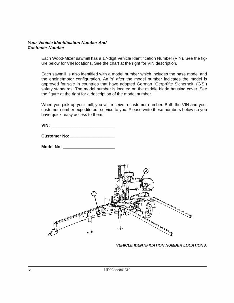
Each Wood-Mizer sawmill has a 17-digit Vehicle Identification Number (VIN). See the fig-ure below for VIN locations. See the chart at the right for VIN description.
Each sawmill is also identified with a model number which includes the base model andthe engine/motor configuration. An ’s’ after the model number indicates the model isapproved for sale in countries that have adopted German "Gerprüfte Sicherheit: (G.S.)safety standards. The model number is located on the middle blade housing cover. Seethe figure at the right for a description of the model number.
When you pick up your mill, you will receive a customer number. Both the VIN and yourcustomer number expedite our service to you. Please write these numbers below so youhave quick, easy access to them.
VIN: ___________________________
Customer No: ___________________
Model No: ______________________
VEHICLE IDENTIFICATION NUMBER LOCATIONS.
iv HD92doc041610
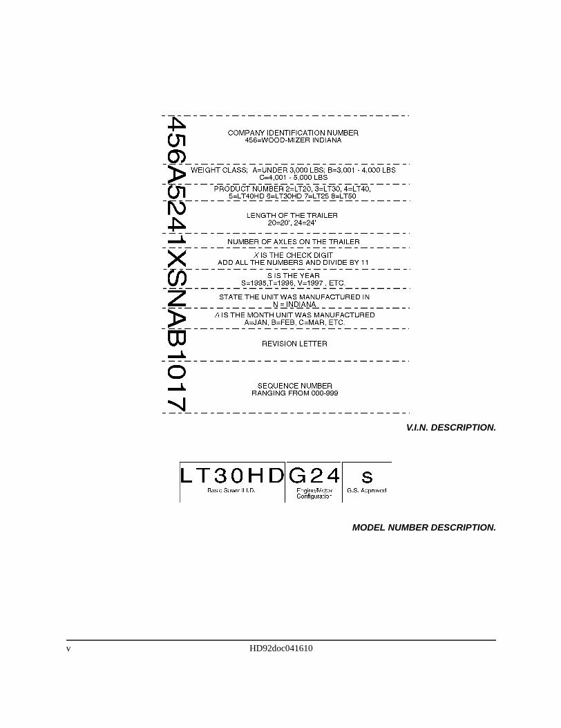
V.I.N. DESCRIPTION.
MODEL NUMBER DESCRIPTION.
v HD92doc041610


Table of Contents Section-Page
SECTION 1 SAFETY & GENERAL INFORMATION 1-1
1.1 Blade Handling.......................................................................................................... 1-11.2 Sawmill Setup............................................................................................................ 1-21.3 Sawmill Operation..................................................................................................... 1-31.4 Electric Sawmill ........................................................................................................ 1-51.5 Belt Sizes ................................................................................................................... 1-91.6 Blade Sizes .............................................................................................................. 1-101.7 Cutting Capacity...................................................................................................... 1-111.8 Engine/Motor Specifications ................................................................................... 1-121.9 Overall Dimensions ................................................................................................. 1-131.10 Components............................................................................................................. 1-141.11 Hydraulic Schematic ............................................................................................... 1-151.12 Hydraulic Components............................................................................................ 1-171.13 Hydraulic Hoses ...................................................................................................... 1-19
SECTION 2 SETUP & OPERATION 2-1
2.1 Stationary Sawmill Setup .......................................................................................... 2-12.2 Portable Sawmill Setup ............................................................................................. 2-22.3 Preparing The Sawmill For Operation ...................................................................... 2-62.4 Replacing The Blade ................................................................................................. 2-72.5 Tensioning The Blade................................................................................................ 2-82.6 Tracking The Blade ................................................................................................... 2-92.7 Starting The Engine (or Motor)............................................................................... 2-112.8 Hydraulic Control Operation................................................................................... 2-122.9 Loading, Turning, And Clamping Logs .................................................................. 2-162.10 Clamp Extension .................................................................................................... 2-192.11 Up/Down Operation ................................................................................................ 2-202.12 Blade Guide Arm Operation.................................................................................... 2-212.13 Clutch/Brake Operation........................................................................................... 2-222.14 Power Feed Operation ............................................................................................. 2-232.15 Cutting The Log ...................................................................................................... 2-252.16 Edging...................................................................................................................... 2-262.17 Blade Height Sight Gauge ....................................................................................... 2-272.18 Blade Height Scale .................................................................................................. 2-282.19 Water Lube Operation ............................................................................................. 2-312.20 Preparing The Sawmill For Towing ........................................................................ 2-32
Table of Contents HD92doc041610 i
Table of Contents Section-Page
SECTION 3 MAINTENANCE 3-1
3.1 Wear Life................................................................................................................... 3-13.2 Blade Guides ............................................................................................................. 3-23.3 Hydraulic Log Loader ............................................................................................... 3-33.4 Blade Housing ........................................................................................................... 3-43.5 Carriage Track, Wiper & Scrapers ............................................................................ 3-53.6 Track Rollers ............................................................................................................. 3-63.7 Vertical Mast Rails .................................................................................................... 3-73.8 Drum Switches .......................................................................................................... 3-83.9 Miscellaneous Lubrication ........................................................................................ 3-93.10 Blade Tensioner....................................................................................................... 3-103.11 Blade Wheel Belts ................................................................................................... 3-113.12 Brake Strap Adjustment .......................................................................................... 3-123.13 Hydraulic System .................................................................................................... 3-143.14 Drive Bearing .......................................................................................................... 3-163.15 Up/Down System..................................................................................................... 3-173.16 Power Feed .............................................................................................................. 3-203.17 Miscellaneous Maintenance .................................................................................... 3-22
SECTION 4 TROUBLESHOOTING GUIDE 4-1
4.1 Sawing Problems ....................................................................................................... 4-14.2 Electrical Problems.................................................................................................... 4-34.3 Power Feed Problems ................................................................................................ 4-54.4 Power Feed Circuit Troubleshooting......................................................................... 4-74.5 Hydraulic Problems ................................................................................................... 4-94.6 Engine/Motor and Drive Pulleys Alignment........................................................... 4-124.7 Power Feed Variable Speed Switch Test................................................................. 4-134.8 Power Feed Preliminary Test .................................................................................. 4-144.9 Power Feed Mechanical Test................................................................................... 4-154.10 Hydraulic Pressure Test........................................................................................... 4-16
Table of Contents HD92doc041610 ii

Table of Contents Section-Page
SECTION 5 SAWMILL ALIGNMENT 5-1
5.1 Pre-Alignment Procedures......................................................................................... 5-15.2 Frame Setup............................................................................................................... 5-25.3 Blade Installation And Alignment............................................................................. 5-35.4 Saw Head Slide Pad Adjustment............................................................................... 5-55.5 Adjusting The Lower Track Rollers.......................................................................... 5-75.6 Adjusting Main Bed Rails To Blade ......................................................................... 5-95.7 Blade Guide Arm Vertical Adjustment ................................................................... 5-115.8 Blade Guide Arm Horizontal Adjustment............................................................... 5-125.9 Aligning The Blade Guides ..................................................................................... 5-145.10 Blade Deflection...................................................................................................... 5-155.11 Blade Guide Vertical Tilt Adjustment..................................................................... 5-165.12 Blade Guide Spacing ............................................................................................... 5-185.13 Horizontal Tilt Adjustment...................................................................................... 5-195.14 Horizontal Adjustment Of Side Supports................................................................ 5-205.15 Vertical Adjustment Of Side Supports .................................................................... 5-215.16 Clamp Stop Adjustment .......................................................................................... 5-225.17 Aligning The Pivot Bed Rails.................................................................................. 5-235.18 Sight Gauge Adjustment.......................................................................................... 5-255.19 Saw Head Tilt .......................................................................................................... 5-265.20 Blade Height Scale Adjustment............................................................................... 5-27
Table of Contents HD92doc041610 iii


Safety & General InformationBlade Handling 1
SECTION 1 SAFETY & GENERAL INFORMATION
This symbol calls your attention to instructions concerning your personal safety. Be sureto observe and follow these instructions. This symbol accompanies a signal word. Theword DANGER refers to hazards that can cause death or serious, irreversible personalinjury. The word WARNING suggests a safety hazard that can cause personal injury.CAUTION refers to hazards that can cause damage to the equipment or property only.
Read all safety instructions before operating this equipment and observe all safety warn-ings!
Safety instructions are listed in this section by the following operations:
Blade Handling
Sawmill Setup
Sawmill Operation
Electric Sawmill
1.1 Blade Handling
WARNING! Always wear gloves and eye protection whenhandling bandsaw blades. Keep all persons away fromarea when coiling or carrying a blade.
Safety & General Information HD92doc041610 1-1
Safety & General InformationSawmill Setup1
1.2 Sawmill Setup
WARNING! Put front outrigger down before moving cuttinghead from the rest position. Failure to do so may result inserious injury.
WARNING! Do not set up the mill on ground with more thana 10 degree incline. If setup on an incline is necessary, putblocks under one side of the mill or dig out areas for outrig-ger legs to keep mill level. Setting up the mill on an inclinecould cause it to tip over, resulting in serious personalinjury.
WARNING! Chock the trailer wheels to prevent movementbefore unhitching it from the towing vehicle. Failure to do somay result in serious injury or death.
WARNING! Always make sure the trailer is supporting thesawmill frame when operating a sawmill with adjustableoutriggers. Failure to do so may result in serious injury ordeath. The adjustable outriggers are intended to supportthe saw frame with assistance from the trailer.
WARNING! The adjustable outriggers supplied with porta-ble sawmills are not intended for setup on concrete or otherhard surfaces. Long-term use of the adjustable outriggerson hard surfaces may cause the outriggers to fail, causingthe sawmill to drop. This could result in possible seriousinjury or death.
If setting the sawmill up on concrete or other hard surface,replace the adjustable outrgger legs with stationary legs.
1-2 HD92doc041610 Safety & General Information
Safety & General InformationSawmill Operation 1
1.3 Sawmill Operation
DANGER! Never operate or tow the sawmill without allguards and covers in place and secured.
Be sure the blade housing and pulley covers are in placeand secure. If applicable, use the safety retainer pin andcable to fasten blade housing covers.
DANGER! Always disengage the clutch/brake mechanismwhenever the sawmill is not cutting.
DANGER! Always keep hands away from moving bandsawblade.
DANGER! Keep all persons a safe distance away fromwork area when operating sawmill or loading and turninglogs.
DANGER! Be sure the power feed switch is in the neutralposition before turning the key switch to the ON or ACCposition. This prevents unwanted carriage movement.
DANGER! Check to be sure the saw head is resting firmlyon the rest pin and mast rail stops and that the safety chainis secured before towing the sawmill.
WARNING! Always secure the cutting head with a 5/16”chain with a least 1900 lbs. working load capacity beforeadjusting the up/down chain. The cutting head may fall,causing severe injury or death.
WARNING! Always secure the cutting head with a 5/16”chain with a least 1900 lbs. working load capacity beforeremoving the up/down motor belt. The cutting head mayfall, causing severe injury or death.
WARNING! Always wear eye, ear, respiration, and foot pro-tection when operating the sawmill.
WARNING! Secure all loose clothing and jewelry beforeoperating the sawmill.
WARNING! Always make sure log is clamped securelybefore sawing.
Safety & General Information HD92doc041610 1-3
Safety & General InformationSawmill Operation1
CAUTION! Always be sure that all safety warning decalsare clean and readable. Replace all damaged warningdecals. Contact your local distributor, or call your CustomerService Representative to order more decals.
CAUTION! Be sure the pivot end rails, turning arm, clamp,and toe boards are out of the way before loading a log ontothe bed. Also, be sure the cutting head is moved far enoughforward so the log does not hit it.
CAUTION! Failure to fully extend the log clamp before tow-ing can result in damage to the clamping assembly duringtowing.
IMPORTANT! It is always the owner's responsibility to com-ply with all applicable federal, state and local laws, rulesand regulations regarding the ownership, operation andtowing of your Wood-Mizer sawmill. All Wood-Mizer millowners are encouraged to become thoroughly familiar withthese applicable laws and comply with them fully whileusing or towing the mill.
Always properly dispose of all sawing byproducts, includingsawdust and other debris.
1-4 HD92doc041610 Safety & General Information

Safety & General InformationElectric Sawmill 1
1.4 Electric Sawmill
USE PROPER PROCEDURE WHEN CONDUCTING ELECTRICAL SAFETY CHECKSAND MAINTENANCE
DANGER! Make sure all electrical installation, service and/ormaintenance work is performed by a qualified electrician and is inaccordance with applicable electrical codes.
DANGER! Hazardous voltage inside the electric sawmill discon-nect box, starter box, and at the motor can cause shock, burns, ordeath. Disconnect and lock out power supply before servicing!Keep all electrical component covers closed and securely fastenedduring mill operation.
WARNING! Consider all electrical circuits energized and danger-ous.
WARNING! Never assume or take the word of another person thatthe power is off; check it out and lock it out.
WARNING! Do not wear rings, watches, or other jewelry whileworking around an open electrical circuit.
WARNING! Before performing service near moving parts such asblades, pulleys, motors, belts and chains, first turn the key switchto the OFF (#0) position and remove the key. If the key is turned onand moving parts activated, serious injury may result.
WARNING! Remove the blade before performing any service tothe engine or sawmill. Failure to do so may result in serious injury.
Safety & General Information HD92doc041610 1-5
Safety & General InformationElectric Sawmill1
DANGER! Lockout procedures must be used during:
Changing or adjusting bladesUnjamming operationsCleaningMechanical repairElectrical maintenanceRetrieval of tools/parts from work areaActivities where guards or electrical panel guard is open orremoved
Maintenance hazards include:
Blade contactPinch pointsKickbacksMissiles (thrown blades/wood chips)Electrical
Failure to lockout may result in:
CutCrushBlindnessPunctureSerious injury and deathAmputationBurnShockElectrocution
To control maintenance dangers:
Lockout procedures must be followed (see ANSI StandardZ244.1-1982 and OSHA regulation 1910.147).Never rely on machine stop control for maintenance safety (emer-gency stops, on/off buttons, interlocks).Do not reach into moving blades or feed systems. Allow all coast-ing parts to come to a complete stop.Electrical power supply and air supply must both be locked out.Where established lockout procedures cannot be used (electricaltroubleshooting or mechanical dynamic troubleshooting), alterna-tive effective protective techniques shall be employed which mayrequire special skills and planning.Always follow safe operations practices in the workplace.
1-6 HD92doc041610 Safety & General Information
Safety & General InformationElectric Sawmill 1
SAWMILL LOCKOUT PROCEDURE
Lockout procedures must be followed (see ANSI Standard Z244.1-1982 and OSHA regu-lation 1910.147).
Purpose:
This procedure establishes the minimum requirements for lockout of energy sources thatcould cause injury.
Responsibility:
The responsibility for seeing that this procedure is followed is binding upon all workers. Allworkers shall be instructed in the safety significance of the lockout procedure. It is yourresponsibility to ensure safe operation of the machine.
Preparation For Lockout:
Sawmillmust be locked out both electrically and pneumatically (lockout air valve).
Sequence of Lockout Procedure:
1. Notify all persons that a lockout is required and the reason therefore.
2. If the Sawmill is operating, shut it down by the normal stopping procedure.
3. Operate the switch and valve so that the energy sources are disconnected or isolatedfrom the Sawmill. Stored energy such as moving blades, feed system and air pressureshall be dissipated.
4. Lockout the energy isolating devices with assigned individual locks.
5. After ensuring that no persons are exposed and as a check on having disconnected theenergy sources, operate the push button or other normal operating controls to make cer-tain the Sawmill will not operate. Caution: Return operating controls to neutral positionafter the test.
6. The Sawmill is now locked out.
Safety & General Information HD92doc041610 1-7
Safety & General InformationElectric Sawmill1
Restoring Equipment to Service
1. When the job is complete and the Sawmill is ready for testing or normal service, checkthe Sawmill area to see that no one is exposed.
2. When the Sawmill is all clear, remove all locks. The energy isolating devices may beoperated to restore energy to the Sawmill.
Procedure Involving More Than One Person
In the preceding steps, if more than one individual is required to lock out the Sawmill,each shall place his own personal lock on the energy isolating devices.
Rules for Using Lockout Procedure
The Sawmill shall be locked out to protect against accidental or inadvertent operationwhen such operation could cause injury to personnel. Do not attempt to operate anyswitch or valve bearing a lock.
Owner’s Responsibility
The procedures listed in this manual may not include all ANSI, OSHA, or locally requiredsafety procedures. It is the owner/operator’s responsibility and not Wood-Mizer Productsto ensure all operators are properly trained and informed of all safety protocols.Owner/Operators are responsible for following all safety procedures when operating andperforming maintenance to the Sawmill.
1-8 HD92doc041610 Safety & General Information
Safety & General InformationBelt Sizes 1
1.5 Belt Sizes
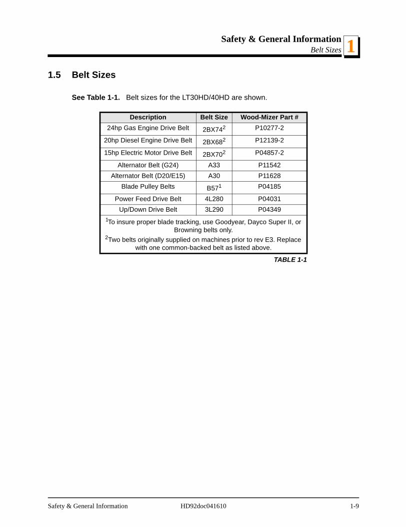
See Table 1-1. Belt sizes for the LT30HD/40HD are shown.
Description Belt Size Wood-Mizer Part #24hp Gas Engine Drive Belt 2BX742 P10277-2
20hp Diesel Engine Drive Belt 2BX682 P12139-2
15hp Electric Motor Drive Belt 2BX702 P04857-2
Alternator Belt (G24) A33 P11542Alternator Belt (D20/E15) A30 P11628
Blade Pulley Belts B571 P04185
Power Feed Drive Belt 4L280 P04031Up/Down Drive Belt 3L290 P04349
1To insure proper blade tracking, use Goodyear, Dayco Super II, or Browning belts only.
2Two belts originally supplied on machines prior to rev E3. Replace with one common-backed belt as listed above.
TABLE 1-1
Safety & General Information HD92doc041610 1-9

Safety & General InformationBlade Sizes1
1.6 Blade Sizes
See Table 1-2. Wood-Mizer TRU•SHARP™ offers three types of blades to provide effi-cient sawing for all models of sawmills. The engine/motor size of your sawmill and thetype of wood you saw should determine which blade you choose for optimum perfor-mance.
See The Blade Handbook for blade hook angle, tooth height, and tooth set specifications.
Gas/Diesel Engine Size
Recommended Blade For Sawing:Softwood Hardwood Frozen or Hard-to-Cut
Wood5 hp - 14hp .042 x 7/8 x 1 1/4” .035 x 7/8 x 1 1/4” .045 x 7/8 x 1 1/4” F 1
1 TRU•SHARP™ “F” blades use a 9/29 profile (9° hook angle and 29° back angle) and are de-signed to cut frozen and/or extremely dense, hard-to-cut wood. Standard TRU•SHARP™blades use a 10/30 profile.
16hp or more .045 x 7/8 x 1 1/2” .042 x 7/8 x 1 1/4”.045 x 7/8 x 1 1/2” 2
2 Customer may choose preferred blade.
.045 x 7/8” x 1 1/4” F1
Electric Motor .045 x 7/8 x 1 1/2” .042 x 7/8 x 1 1/4”.045 x 7/8 x 1 1/2” 2
.045 x 7/8 x 1 1/4” F1
TABLE 1-2
1-10 HD92doc041610 Safety & General Information
Safety & General InformationCutting Capacity 1
1.7 Cutting Capacity
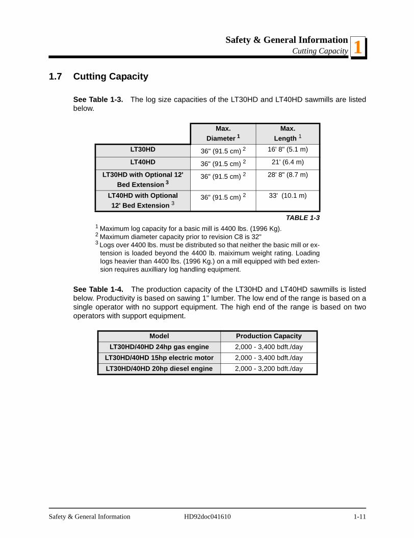
See Table 1-3. The log size capacities of the LT30HD and LT40HD sawmills are listedbelow.
See Table 1-4. The production capacity of the LT30HD and LT40HD sawmills is listedbelow. Productivity is based on sawing 1" lumber. The low end of the range is based on asingle operator with no support equipment. The high end of the range is based on twooperators with support equipment.
Max.Diameter 1
1 Maximum log capacity for a basic mill is 4400 lbs. (1996 Kg).
Max.Length 1
LT30HD 36" (91.5 cm) 2
2 Maximum diameter capacity prior to revision C8 is 32"
16' 8" (5.1 m)
LT40HD 36" (91.5 cm) 2 21' (6.4 m)
LT30HD with Optional 12' Bed Extension 3
3 Logs over 4400 lbs. must be distributed so that neither the basic mill or ex-tension is loaded beyond the 4400 lb. maiximum weight rating. Loadinglogs heavier than 4400 lbs. (1996 Kg.) on a mill equipped with bed exten-sion requires auxilliary log handling equipment.
36" (91.5 cm) 2 28' 8" (8.7 m)
LT40HD with Optional12' Bed Extension 3
36" (91.5 cm) 2 33' (10.1 m)
TABLE 1-3
Model Production CapacityLT30HD/40HD 24hp gas engine 2,000 - 3,400 bdft./day
LT30HD/40HD 15hp electric motor 2,000 - 3,400 bdft./dayLT30HD/40HD 20hp diesel engine 2,000 - 3,200 bdft./day
Safety & General Information HD92doc041610 1-11

Safety & General InformationEngine/Motor Specifications1
1.8 Engine/Motor Specifications
See Table 1-5. The power options available for the LT30HD and LT40HD sawmills arelisted below.
Engine/Motor Type
Manufacturer Model Number
24HP Gasoline Onan P22420HP Diesel Acme ADX74015HP Electric Baldor Custom
TABLE 1-5
1-12 HD92doc041610 Safety & General Information
Safety & General InformationOverall Dimensions 1
1.9 Overall Dimensions
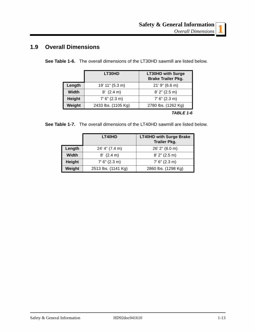
See Table 1-6. The overall dimensions of the LT30HD sawmill are listed below.
See Table 1-7. The overall dimensions of the LT40HD sawmill are listed below.
LT30HD LT30HD with Surge Brake Trailer Pkg.
Length 19' 11" (5.3 m) 21' 9" (6.6 m)Width 8' (2.4 m) 8' 2" (2.5 m)Height 7' 6" (2.3 m) 7' 6" (2.3 m)Weight 2433 lbs. (1105 Kg) 2780 lbs. (1262 Kg)
TABLE 1-6
LT40HD LT40HD with Surge Brake Trailer Pkg.
Length 24' 4" (7.4 m) 26' 2" (8.0 m)Width 8' (2.4 m) 8' 2" (2.5 m)Height 7' 6" (2.3 m) 7' 6" (2.3 m)Weight 2513 lbs. (1141 Kg) 2860 lbs. (1298 Kg)
Safety & General Information HD92doc041610 1-13
Safety & General InformationComponents1
rm
licder
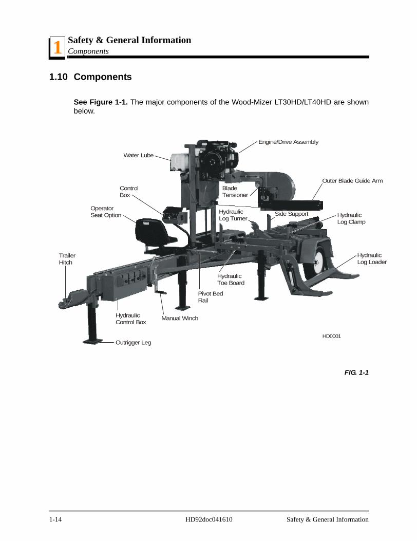
1.10 Components
See Figure 1-1. The major components of the Wood-Mizer LT30HD/LT40HD are shownbelow.
FIG. 1-1
TrailerHitch
OperatorSeat Option
ControlBox
Water Lube
Engine/Drive Assembly
Outer Blade Guide ABladeTensioner
HydraulicLog Clamp
HydrauLog Loa
HydraulicLog Turner
Side Support
HydraulicToe Board
Pivot BedRail
Outrigger Leg
Manual WinchHydraulicControl Box
HD0001
1-14 HD92doc041610 Safety & General Information
Safety & General InformationHydraulic Schematic 1
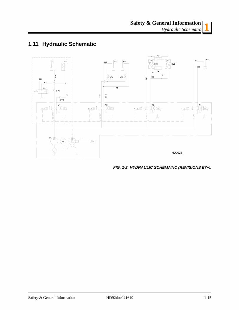
1.11 Hydraulic Schematic
FIG. 1-2 HYDRAULIC SCHEMATIC (REVISIONS E7+).
Safety & General Information HD92doc041610 1-15
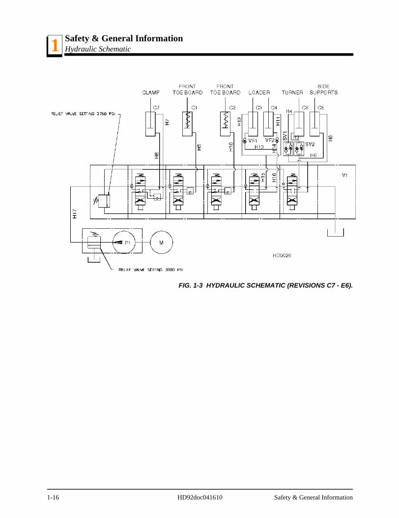
Safety & General InformationHydraulic Schematic1
FIG. 1-3 HYDRAULIC SCHEMATIC (REVISIONS C7 - E6).
1-16 HD92doc041610 Safety & General Information

Safety & General InformationHydraulic Components 1
e,
e,
v.
v.
v.
vice
1.12 Hydraulic ComponentsREVISIONS E7+
Compo-nent
Mfg. Part No. Manufacturer Wood-Mizer Part.#
Description
C1 A09665 Wood-Mizer A09665 Hydraulic Cylinder, 1.5" Bore X 3.5" StrokSpring Return
C2 A09665 Wood-Mizer A09665 Hydraulic Cylinder, 1.5" Bore X 3.5" StrokSpring Return
C3 P12847 J-D Hydraulic P12847 1
1 Welded cylinder P12847 replaces tie rod cylinder P09128 originally supplied before Rev. F5.
Hydraulic Cylinder, 3" Bore X 8" Stroke (ReF5+)
TQ3008 Q0002
Monarch Can. P09128 2
2 Use tie rod cylinder P09128 for Rev. C7 - F4.
Hydraulic Cylinder, 3" Bore X 8" Stroke (ReE7 - F4)
TQ3008 Q0002
Monarch Can. P09128 2 Hydraulic Cylinder, 3" Bore X 8" Stroke (ReE7 - F4)
C5 P12845 J-D Hydraulic P12845 3
3 Welded cylinder P12845 replaces tie rod cylinder P09125 originally supplied before Rev. F5.
Hydraulic Cylinder, 2" Bore X 6" Stroke
C6 P12846 J-D Hydraulic P12846 4
4 Welded cylinder P12846 replaces tie rod cylinder P09127 originally supplied before Rev. F5
Hydraulic Cylinder, 2.5" Bore X 6" Stroke
C7 P12847 J-D Hydraulic P12847 1 Hydraulic Cylinder, 3" Bore X 8" Stroke
P1 Monarch Hyd. N/A Hydraulic Pump, Motor DrivenSV1 A09207 Wood-Mizer A09207 Sequence ValveSV2 A09207 Wood-Mizer A09207 Sequence ValveV1 07129 Monarch Hyd. P12700 Valve, 5-Valve Salami
VF1 28000-502-2.5 Vonberg P11566 Valve, Hydraulic Velocity FuseVF2 28000-502-2.5 Vonberg P11566 Valve, Hydraulic Velocity FuseM 08058 5
5 Replaces Monarch #08111 originally supplied before 8/94.
Monarch Hyd. P09955 6
6 Bosch motor P09955 replaced by vendor with Iksra motor 1/06. Brush kit P09585 no longer available to serBosch motor. Replace motor using kit 052807. Use Brush Kit 038682 to service Iksra motor.
Motor, Hydraulic Pump
Safety & General Information HD92doc041610 1-17

Safety & General InformationHydraulic Components1
Of
Of
Of
Of
vice
REVISIONS C7 - E6
Compo-nent
Manufacturer Part No.
Manufacturer Wood-Mizer Part
No.
Description
C1 A09665 Wood-Mizer A09665 Hydraulic Cylinder, 1.5" Bore X 3.5" Stroke,Spring Return
C2 A09665 Wood-Mizer A09665 Hydraulic Cylinder, 1.5" Bore X 3.5" Stroke,Spring Return
C3 TQ3008 Q0002 Monarch Can. P09128 Hydraulic Cylinder, 3" Bore X 8" StrokeC4 TQ3008 Q0002 Monarch Can. P09128 Hydraulic Cylinder, 3" Bore X 8" StrokeC5 P12845 J-D Hydraulic P12845 1
1 Welded cylinder P12845 replaces tie rod cylinder P09125 originally supplied.
Hydraulic Cylinder, 2" Bore X 6" Stroke
C6 P12846 J-D Hydraulic P12846 2
2 Welded cylinder P12846 replaces tie rod cylinder P09127 originally supplied.
Hydraulic Cylinder, 2.5" Bore X 6" Stroke
C7 P12847 J-D Hydraulic P12847 3
3 Welded cylinder P12847 replaces tie rod cylinder P09128 originally supplied.
Hydraulic Cylinder, 3" Bore X 8" Stroke
CV1 A11687 Wood-Mizer A11687 Check ValveCV2 A11687 Wood-Mizer A11687 Check ValveP1 O2414 Monarch Hyd. N/A Hydraulic Pump, Motor Driven
SV1 A09207 Wood-Mizer A09207 Sequence ValveSV2 A09207 Wood-Mizer A09207 Sequence ValveV1 00647 Monarch Hyd. P11581 Valve, 4-way Manually Operated (Integral Part
P/N P10371)V2 00524 Monarch Hyd. P10143 Valve, 4-way Manually Operated (Integral Part
P/N P10371)V3 00524 Monarch Hyd. P10143 Valve, 4-way Manually Operated (Integral Part
P/N P10371)V4 00524 Monarch Hyd. P10143 Valve, 4-way Manually Operated (Integral Part
P/N P10371)V5 A09680 Wood-Mizer A09680 Dump Valve, Manually Operated
VF1 28000-502-2.5 Vonberg P11566 Valve, Hydraulic Velocity FuseVF2 28000-502-2.5 Vonberg P11566 Valve, Hydraulic Velocity FuseM 08058 4
4 Replaces Monarch #08111 originally supplied.
Monarch Hyd. P09955 5
5 Bosch motor P09955 replaced by vendor with Iksra motor 1/06. Brush kit P09585 no longer available to serBosch motor. Replace motor using kit 052807. Use Brush Kit 038682 to service Iksra motor.
Motor, Hydraulic Pump
1-18 HD92doc041610 Safety & General Information

Safety & General InformationHydraulic Hoses 1
1.13 Hydraulic Hoses
REVISIONS F5+
Compo-nent
Color Code
Application Wood-Mizer Part No.
Description
H3 Plain Log Turner Cylinder Base P12533 Hose, 1/4" X 14" Hydraulic W/Fittings
H4 Orange Log Turner Cylinder Top P12535 Hose, 1/4" X 27" Hydraulic W/Fittings
H5 Yellow Front Toe Board (LT30HD) P12539 Hose, 1/4" X 84" Hydraulic W/Fittings
Yellow Front Toe Board (LT40HD) P12541 Hose, 1/4" X 106" Hydraulic W/Fittings
H6 Pink Side Support Cylinder Base (LT30HD)
P12545 Hose, 1/4" X 151" Hydraulic W/Fittings
Pink Side Support Cylinder Base (LT40HD)
P12549 Hose, 1/4" X 173" Hydraulic W/Fittings
H7 White Clamp Cylinder Top (LT30HD) P12544 Hose, 1/4" X 142" Hydraulic W/Fittings
White Clamp Cylinder Top (LT40HD) P12548 Hose, 1/4" X 164" Hydraulic W/Fittings
H8 Dark Orange
Clamp Cylinder Base (LT30HD) P12543 Hose, 1/4" X 135" Hydraulic W/Fittings
Dark Orange
Clamp Cylinder Base (LT40HD) P12546 Hose, 1/4" X 157" Hydraulic W/Fittings
H9 Plain Side Support Cylinder Top (LT30HD)
P12547 Hose, 1/4" X 159" Hydraulic W/Fittings
Plain Side Support Cylinder Top (LT40HD)
P12550 Hose, 1/4" X 186" Hydraulic W/Fittings
H10 Purple Rear Toe Board (LT30HD) P12549 Hose, 1/4" X 173" Hydraulic W/Fittings
Purple Rear Toe Board (LT40HD) P12551 Hose, 1/4" X 197" Hydraulic W/Fittings
H11 Green Loading Arm Branch Top P12537 Hose, 1/4" X 50" Hydraulic W/Fittings
H12 Green Loading Arm Branch Top P12537 Hose, 1/4" X 50" Hydraulic W/Fittings
H13 Yellow Loading Arm Branch Base P12538 Hose, 1/4" X 55" Hydraulic W/Fittings
H14 Yellow Loading Arm Branch Base P12538 Hose, 1/4" X 55" Hydraulic W/Fittings
Safety & General Information HD92doc041610 1-19

Safety & General InformationHydraulic Hoses1
H15 Blue Loading Arm Cylinder Top (LT30HD)
P12545 Hose, 1/4" X 151" Hydraulic W/Fittings
Blue Loading Arm Cylinder Top (LT40HD)
P12549 Hose, 1/4" X 173" Hydraulic W/Fittings
H16 Red Loading Arm Cylinder Bottom (LT30HD)
P12545 Hose, 1/4" X 151" Hydraulic W/Fittings
Red Loading Arm Cylinder Bottom (LT40HD)
P12549 Hose, 1/4" X 173" Hydraulic W/Fittings
H17 None Hydraulic Pump To Valve P12705 Hose, 3/8" X 22" Hydraulic W/Fittings
REVISIONS F5+
1-20 HD92doc041610 Safety & General Information

Safety & General InformationHydraulic Hoses 1
REVISIONS C7 - F4
Compo-nent
Color Code
Application Wood-Mizer Part No.
Description
H1 Brown Toe Board Return (Rev. C7- E6 Only)
P12534 Hose, 1/4" X 22" Hydraulic W/Fittings
H2 Brown Toe Board Return (Rev. C7- E6 Only)
P12534 Hose, 1/4" X 22" Hydraulic W/Fittings
H3 Gold Log Turner Cylinder Base P12533 Hose, 1/4" X 14" Hydraulic W/Fittings
H4 Grey Log Turner Cylinder Top P12535 Hose, 1/4" X 27" Hydraulic W/Fittings
H5 Bright Yel-low
Front Toe Board (LT30HD) P12539 Hose, 1/4" X 84" Hydraulic W/Fittings
Bright Yel-low
Front Toe Board (LT40HD) P12541 Hose, 1/4" X 106" Hydraulic W/Fittings
H6 Silver Side Support Cylinder Base (LT30HD)
P12545 Hose, 1/4" X 151" Hydraulic W/Fittings
Silver Side Support Cylinder Base (LT40HD)
P12549 Hose, 1/4" X 173" Hydraulic W/Fittings
H7 White Clamp Cylinder Top (LT30HD) P12544 Hose, 1/4" X 142" Hydraulic W/Fittings
White Clamp Cylinder Top (LT40HD) P12548 Hose, 1/4" X 164" Hydraulic W/Fittings
H8 Orange Clamp Cylinder Base (LT30HD) P12543 Hose, 1/4" X 135" Hydraulic W/Fittings
Orange Clamp Cylinder Base (LT40HD) P12546 Hose, 1/4" X 157" Hydraulic W/Fittings
H9 Plain Side Support Cylinder Top (LT30HD)
P12547 Hose, 1/4" X 159" Hydraulic W/Fittings
Plain Side Support Cylinder Top (LT40HD)
P12550 Hose, 1/4" X 186" Hydraulic W/Fittings
H10 Black Rear Toe Board (LT30HD) P12549 Hose, 1/4" X 173" Hydraulic W/Fittings
Black Rear Toe Board (LT40HD) P12551 Hose, 1/4" X 208" Hydraulic W/Fittings
H11 Dark Green
Loading Arm Branch Top P12537 Hose, 1/4" X 52" Hydraulic W/Fittings
H12 Dark Green
Loading Arm Branch Top P12537 Hose, 1/4" X 52" Hydraulic W/Fittings
H13 Dark Yel-low
Loading Arm Branch Base P12538 Hose, 1/4" X 55" Hydraulic W/Fittings
H14 Dark Yel-low
Loading Arm Branch Base P12538 Hose, 1/4" X 55" Hydraulic W/Fittings
Safety & General Information HD92doc041610 1-21

Safety & General InformationHydraulic Hoses1
H15 Blue Loading Arm Cylinder Top (LT30HD)
P12545 Hose, 1/4" X 151" Hydraulic W/Fittings
Blue Loading Arm Cylinder Top (LT40HD)
P12549 Hose, 1/4" X 173" Hydraulic W/Fittings
H16 Red Loading Arm Cylinder Bottom (LT30HD)
P12545 Hose, 1/4" X 151" Hydraulic W/Fittings
Red Loading Arm Cylinder Bottom (LT40HD)
P12549 Hose, 1/4" X 173" Hydraulic W/Fittings
H17 None Hydraulic Pump To Valve (Rev. E7+Only)
P12705 Hose, 3/8" X 22" Hydraulic W/Fittings
REVISIONS C7 - F4
1-22 HD92doc041610 Safety & General Information
Setup & OperationStationary Sawmill Setup 2
SECTION 2 SETUP & OPERATION
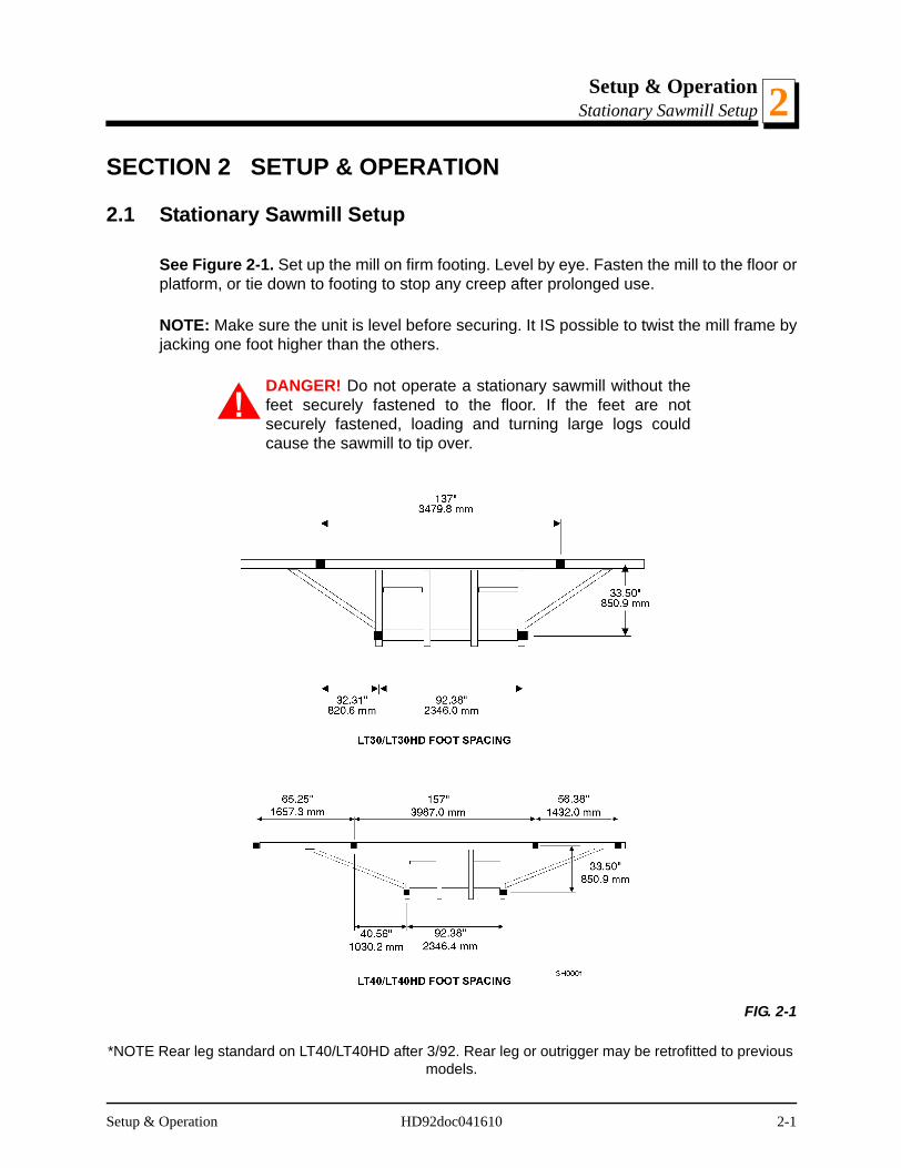
2.1 Stationary Sawmill Setup
See Figure 2-1. Set up the mill on firm footing. Level by eye. Fasten the mill to the floor orplatform, or tie down to footing to stop any creep after prolonged use.
NOTE: Make sure the unit is level before securing. It IS possible to twist the mill frame byjacking one foot higher than the others.
DANGER! Do not operate a stationary sawmill without thefeet securely fastened to the floor. If the feet are notsecurely fastened, loading and turning large logs couldcause the sawmill to tip over.
*NOTE Rear leg standard on LT40/LT40HD after 3/92. Rear leg or outrigger may be retrofitted to previous models.
FIG. 2-1
Setup & Operation HD92doc041610 2-1
Setup & OperationPortable Sawmill Setup2
2.2 Portable Sawmill Setup
WARNING! Do not set up the mill on ground with more thana 10 degree incline. If setup on an incline is necessary, putblocks under one side of the mill or dig out areas for outrig-ger legs to keep mill level. Setting up the mill on an inclinecould cause it to tip over, resulting in serious personalinjury.
WARNING! Chock the trailer wheels to prevent movementbefore unhitching it from the towing vehicle. Failure to do somay result in serious injury or death.
WARNING! Always make sure the trailer is supporting thesawmill frame when operating a sawmill with adjustableoutriggers. Failure to do so may result in serious injury ordeath. The adjustable outriggers are intended to supportthe saw frame with assistance from the trailer.
WARNING! The adjustable outriggers supplied with porta-ble sawmills are not intended for setup on concrete or otherhard surfaces. Long-term use of the adjustable outriggerson hard surfaces may cause the outriggers to fail, causingthe sawmill to drop. This could result in possible seriousinjury or death.
If setting the sawmill up on concrete or other hard surface,replace the adjustable outrgger legs with stationary legs.
2-2 HD92doc041610 Setup & Operation
Setup & OperationPortable Sawmill Setup 2
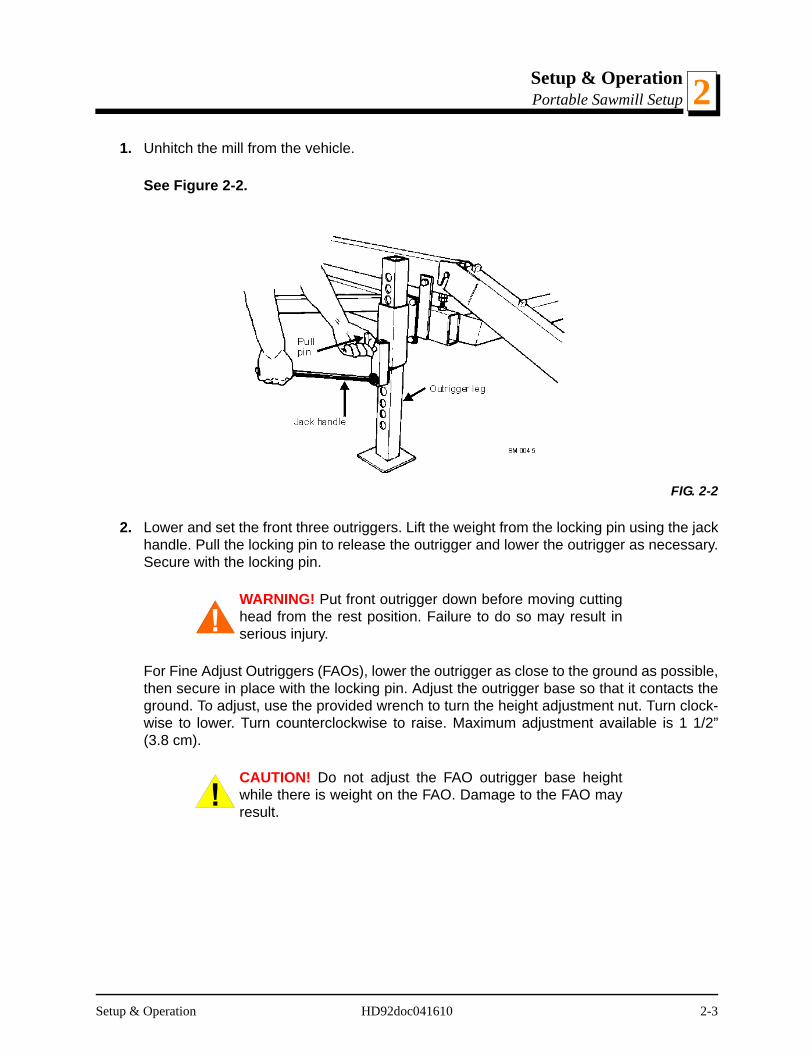
1. Unhitch the mill from the vehicle.
See Figure 2-2.
2. Lower and set the front three outriggers. Lift the weight from the locking pin using the jackhandle. Pull the locking pin to release the outrigger and lower the outrigger as necessary.Secure with the locking pin.
WARNING! Put front outrigger down before moving cuttinghead from the rest position. Failure to do so may result inserious injury.
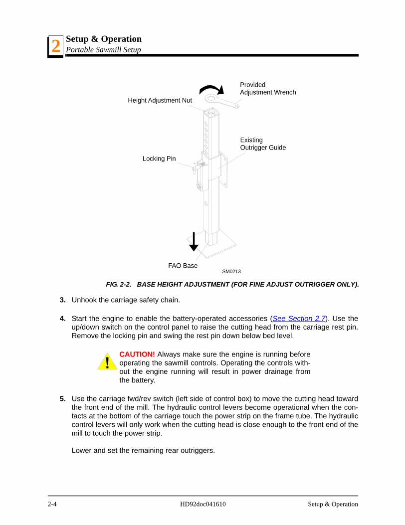
For Fine Adjust Outriggers (FAOs), lower the outrigger as close to the ground as possible,then secure in place with the locking pin. Adjust the outrigger base so that it contacts theground. To adjust, use the provided wrench to turn the height adjustment nut. Turn clock-wise to lower. Turn counterclockwise to raise. Maximum adjustment available is 1 1/2”(3.8 cm).
CAUTION! Do not adjust the FAO outrigger base heightwhile there is weight on the FAO. Damage to the FAO mayresult.
FIG. 2-2
Setup & Operation HD92doc041610 2-3
Setup & OperationPortable Sawmill Setup2
3. Unhook the carriage safety chain.
4. Start the engine to enable the battery-operated accessories (See Section 2.7). Use theup/down switch on the control panel to raise the cutting head from the carriage rest pin.Remove the locking pin and swing the rest pin down below bed level.
CAUTION! Always make sure the engine is running beforeoperating the sawmill controls. Operating the controls with-out the engine running will result in power drainage fromthe battery.
5. Use the carriage fwd/rev switch (left side of control box) to move the cutting head towardthe front end of the mill. The hydraulic control levers become operational when the con-tacts at the bottom of the carriage touch the power strip on the frame tube. The hydrauliccontrol levers will only work when the cutting head is close enough to the front end of themill to touch the power strip.
Lower and set the remaining rear outriggers.
FIG. 2-2. BASE HEIGHT ADJUSTMENT (FOR FINE ADJUST OUTRIGGER ONLY).
SM0213FAO Base
Height Adjustment Nut
Locking Pin
Provided Adjustment Wrench
Existing Outrigger Guide
2-4 HD92doc041610 Setup & Operation
Setup & OperationPortable Sawmill Setup 2
6. Level the sawmill by adjusting the outriggers to raise or lower each end of the sawmill.Adjust all outriggers evenly to avoid twisting the mill frame by jacking one outrigger higherthan the others.
For FAO(s), fine tune the outrigger base height as necessary. Move the cutting head tothe opposite end of the mill from the outrigger. Raise the entire outrigger (to remove thesawmill weight from it) and adjust the outrigger base as necessary. Lower the entire out-rigger and use the locking pin to secure in position.
CAUTION! Do not adjust the FAO outrigger base heightwhile there is weight on the FAO. Damage to the FAO mayresult.
7. Remove the fenders by lifting them out of the slots.
CAUTION! To prevent fender damage, remove fendersbefore operating sawmill or loading logs.
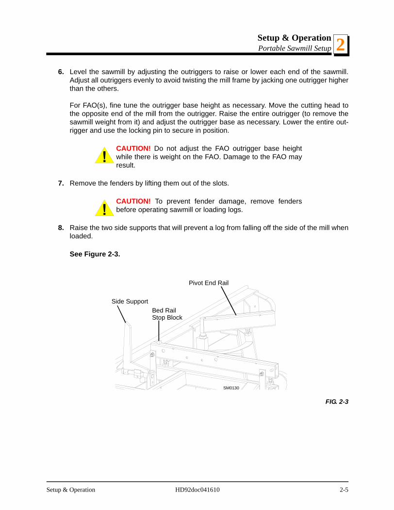
8. Raise the two side supports that will prevent a log from falling off the side of the mill whenloaded.
See Figure 2-3.
FIG. 2-3
SM0130
Bed RailStop Block
Pivot End Rail
Side Support
Setup & Operation HD92doc041610 2-5
Setup & OperationPreparing The Sawmill For Operation2
2.3 Preparing The Sawmill For Operation
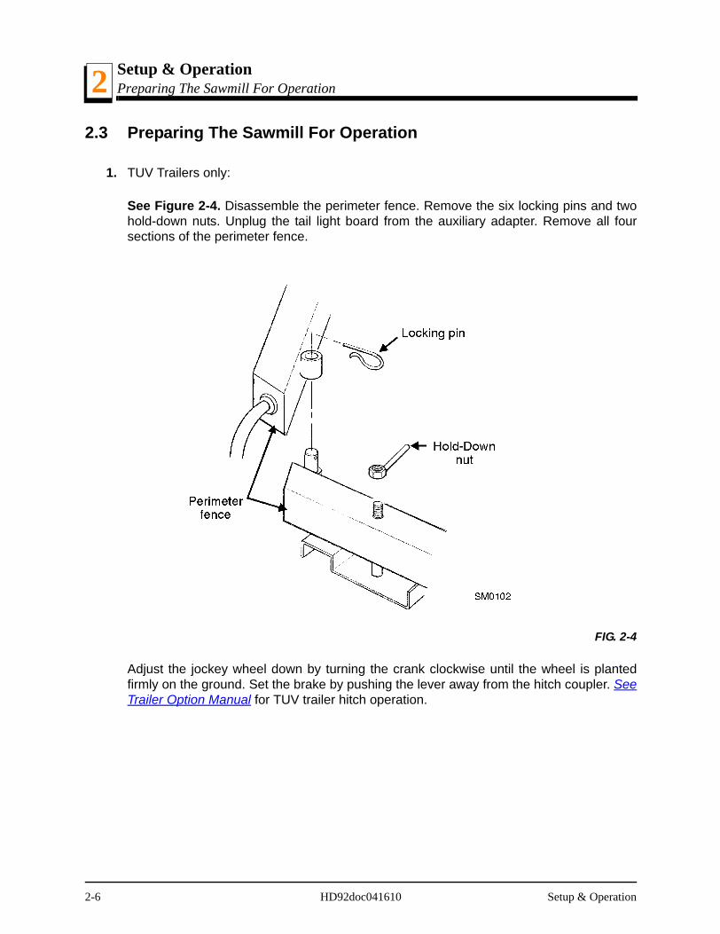
1. TUV Trailers only:
See Figure 2-4. Disassemble the perimeter fence. Remove the six locking pins and twohold-down nuts. Unplug the tail light board from the auxiliary adapter. Remove all foursections of the perimeter fence.
Adjust the jockey wheel down by turning the crank clockwise until the wheel is plantedfirmly on the ground. Set the brake by pushing the lever away from the hitch coupler. SeeTrailer Option Manual for TUV trailer hitch operation.
FIG. 2-4
2-6 HD92doc041610 Setup & Operation

Setup & OperationReplacing The Blade 2
2.4 Replacing The Blade
WARNING! Always wear gloves and eye protection when-ever handling bandsaw blades. Changing blades is safestwhen done by one person! Keep all other persons awayfrom work area when changing blades. Do not change theblade with the engine running.
See Figure 2-5. Remove the blade housing cover(s) that are over the drive wheels. Turnthe tension handle to release the blade tension until the wheel is pulled in and the blade islying loose in the blade housing. Lift the blade out of the blade housing.
When installing a blade, make sure the teeth are pointing the correct direction. The teethshould be pointing toward the operator side of the mill when you are looking at the bladebelow the blade guides. Install the blade so it is lying around the wheels.
Position 1 1/4” wide blades on the wheels so the gullet is 1/8" (3.0 mm) out from the edgeof the wheel. Position 1 1/2” wide blades on the wheels so the gullet is 3/16” (4.5 mm) outfrom the edge of the wheel.
Close the middle blade housing cover.
Next, turn the tension handle until the blade is tensioned correctly.
Setup & Operation HD92doc041610 2-7
Setup & OperationTensioning The Blade2
2.5 Tensioning The Blade
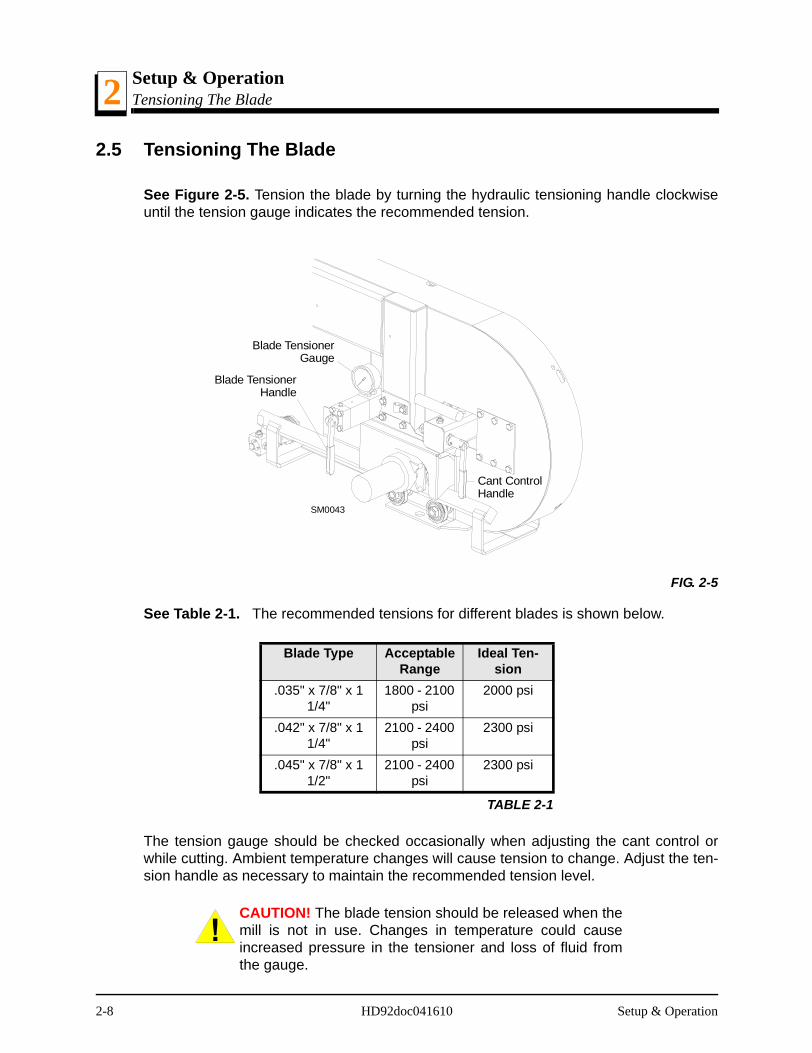
See Figure 2-5. Tension the blade by turning the hydraulic tensioning handle clockwiseuntil the tension gauge indicates the recommended tension.
See Table 2-1. The recommended tensions for different blades is shown below.
The tension gauge should be checked occasionally when adjusting the cant control orwhile cutting. Ambient temperature changes will cause tension to change. Adjust the ten-sion handle as necessary to maintain the recommended tension level.
CAUTION! The blade tension should be released when themill is not in use. Changes in temperature could causeincreased pressure in the tensioner and loss of fluid fromthe gauge.
FIG. 2-5
Blade Type Acceptable Range
Ideal Ten-sion
.035" x 7/8" x 1 1/4"
1800 - 2100 psi
2000 psi
.042" x 7/8" x 1 1/4"
2100 - 2400 psi
2300 psi
.045" x 7/8" x 1 1/2"
2100 - 2400 psi
2300 psi
TABLE 2-1
SM0043
Blade TensionerGauge
Cant ControlHandle
Blade TensionerHandle
2-8 HD92doc041610 Setup & Operation
Setup & OperationTracking The Blade 2
2.6 Tracking The Blade
Make sure the middle blade housing cover is closed and all persons are clear of the openside of the saw head.
Start the engine (or motor). Pull lightly on the clutch handle, rotating the blade until theblade positions itself on the wheels.
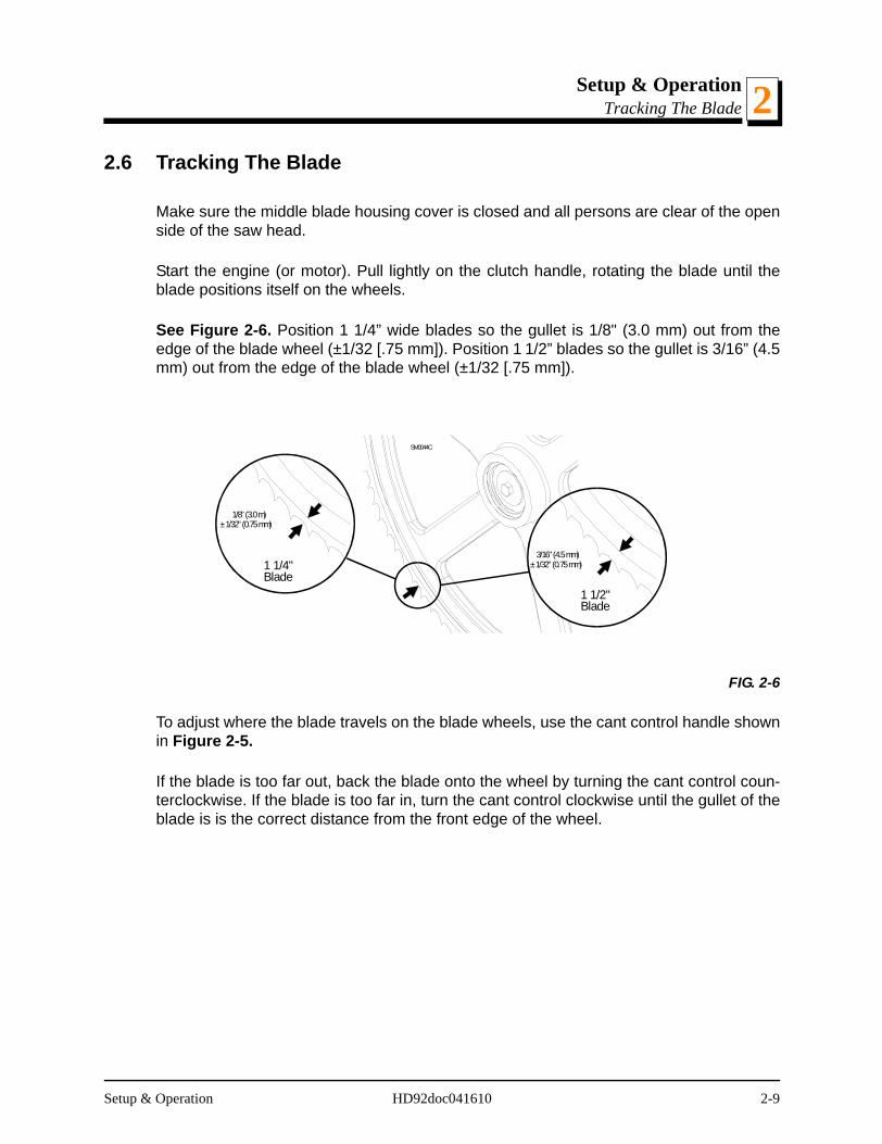
See Figure 2-6. Position 1 1/4” wide blades so the gullet is 1/8" (3.0 mm) out from theedge of the blade wheel (±1/32 [.75 mm]). Position 1 1/2” blades so the gullet is 3/16” (4.5mm) out from the edge of the blade wheel (±1/32 [.75 mm]).
To adjust where the blade travels on the blade wheels, use the cant control handle shownin Figure 2-5.
If the blade is too far out, back the blade onto the wheel by turning the cant control coun-terclockwise. If the blade is too far in, turn the cant control clockwise until the gullet of theblade is is the correct distance from the front edge of the wheel.
FIG. 2-6
SM0044C
3/16" (4.5 mm)± 1/32" (0.75 mm)
1 1/2"Blade
1/8" (3.0 m)± 1/32" (0.75 mm)
1 1/4"Blade
Setup & Operation HD92doc041610 2-9

Setup & OperationTracking The Blade2
Retension the blade to the recommended tension to compensate for any adjustments youhave made in the cant control. Replace the covers.
DANGER! Never operate the sawmill without all guardsand covers in place and secured.
Be sure the blade housing and pulley covers are in place and secure. If applicable, usethe safety retainer pin and cable to fasten blade housing covers.
IMPORTANT! After aligning the blade on the wheels,always double-check the blade guide spacing and location.See Section 5 for more information.
2-10 HD92doc041610 Setup & Operation
Setup & OperationStarting The Engine (or Motor) 2
2.7 Starting The Engine (or Motor)
See the appropriate manual supplied with your specific engine/motor configuration forstarting and operating instructions.
DANGER! Read the entire manual before operating yourWood-Mizer sawmill.
DANGER! Never operate the sawmill without all guardsand covers in place and secured.
Be sure the blade housing and pulley covers are in place and secure before starting thesawmill. If applicable, use the safety retainer pin and cable to fasten blade housing cov-ers.
DANGER! Do not start the engine or motor when theclutch/brake lever is in the engaged (down) position.Always be sure the blade is disengaged and all persons areaway from the blade before starting the engine.
DANGER! Make sure the carriage fwd/rev switch is in theneutral position before turning the key switch to the ON orACC position. This will prevent unintended carriage move-ment.
WARNING! Always wear eye, ear, and respiration protec-tion when operating this equipment.
Setup & Operation HD92doc041610 2-11
Setup & OperationHydraulic Control Operation2
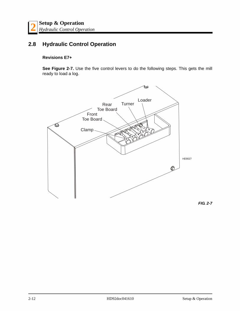
2.8 Hydraulic Control Operation
Revisions E7+
See Figure 2-7. Use the five control levers to do the following steps. This gets the millready to load a log.
FIG. 2-7
RearToe Board
LoaderTurner
Clamp
FrontToe Board
HD0027
2-12 HD92doc041610 Setup & Operation
Setup & OperationHydraulic Control Operation 2
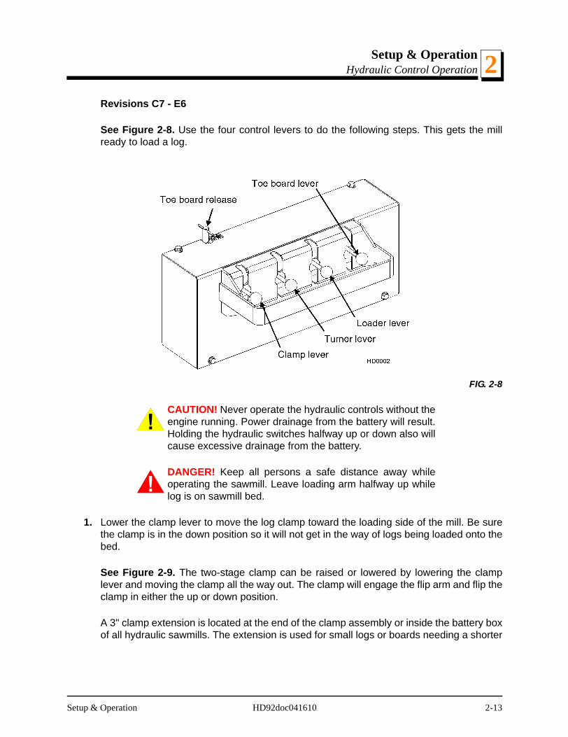
Revisions C7 - E6
See Figure 2-8. Use the four control levers to do the following steps. This gets the millready to load a log.
CAUTION! Never operate the hydraulic controls without theengine running. Power drainage from the battery will result.Holding the hydraulic switches halfway up or down also willcause excessive drainage from the battery.
DANGER! Keep all persons a safe distance away whileoperating the sawmill. Leave loading arm halfway up whilelog is on sawmill bed.
1. Lower the clamp lever to move the log clamp toward the loading side of the mill. Be surethe clamp is in the down position so it will not get in the way of logs being loaded onto thebed.
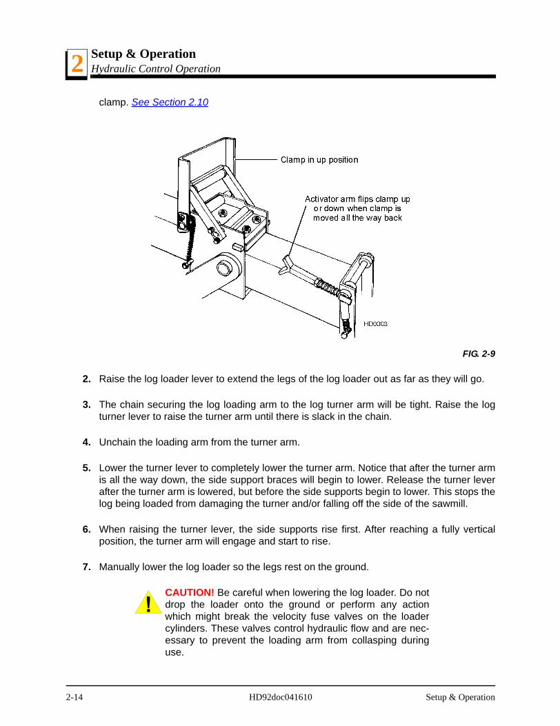
See Figure 2-9. The two-stage clamp can be raised or lowered by lowering the clamplever and moving the clamp all the way out. The clamp will engage the flip arm and flip theclamp in either the up or down position.
A 3" clamp extension is located at the end of the clamp assembly or inside the battery boxof all hydraulic sawmills. The extension is used for small logs or boards needing a shorter
FIG. 2-8
Setup & Operation HD92doc041610 2-13
Setup & OperationHydraulic Control Operation2
clamp. See Section 2.10
2. Raise the log loader lever to extend the legs of the log loader out as far as they will go.
3. The chain securing the log loading arm to the log turner arm will be tight. Raise the logturner lever to raise the turner arm until there is slack in the chain.
4. Unchain the loading arm from the turner arm.
5. Lower the turner lever to completely lower the turner arm. Notice that after the turner armis all the way down, the side support braces will begin to lower. Release the turner leverafter the turner arm is lowered, but before the side supports begin to lower. This stops thelog being loaded from damaging the turner and/or falling off the side of the sawmill.
6. When raising the turner lever, the side supports rise first. After reaching a fully verticalposition, the turner arm will engage and start to rise.
7. Manually lower the log loader so the legs rest on the ground.
CAUTION! Be careful when lowering the log loader. Do notdrop the loader onto the ground or perform any actionwhich might break the velocity fuse valves on the loadercylinders. These valves control hydraulic flow and are nec-essary to prevent the loading arm from collasping duringuse.
FIG. 2-9
2-14 HD92doc041610 Setup & Operation
Setup & OperationHydraulic Control Operation 2
8. Lower the loader lever to lower the loading arm as far as it will go. Logs must be rolledonto the loading arm one at a time for loading onto the bed of the mill.
9. The front and rear toe boards should be below bed level. Once a tapered log has beenloaded, the front or rear end of the log may be lifted to parallel the heart of the log to thepath of the blade.
Revisions E7+
The front toe board is raised by lifting the front toe board lever up. The rear toe board israised by lifting the rear toe board lever up. Once a flat has been made and the log isready to be turned, push the appropriate toe board lever down to lower either toe boarduntil it falls below the level of the bed.
Revisions C7 - E6
The front toe board is raised by lifting the toe board lever up. The rear toe board is raisedby pushing the lever down. Once a flat has been made and the log is ready to be turned,the toe board release valve should be turned clockwise to lower either toe board until itfalls below the level of the bed.
CAUTION! Always be sure the toe boards are loweredbelow bed level before turning or loading logs onto the bed.Loading and turning logs or cants can cause permanentdamage to the toe boards if they are left in the up position.
Setup & Operation HD92doc041610 2-15
Setup & OperationLoading, Turning, And Clamping Logs2
2.9 Loading, Turning, And Clamping Logs
CAUTION! Be sure the pivot end rails (if applicable), turn-ing arm, clamp, and toe boards are out of the way beforeloading a log onto the bed. Be sure logs are positioned onthe bed so that they will not damage the manual winchwhen loaded. Also, be sure the cutting head is moved farenough forward so the log does not hit it.
To Load Logs
1. Move a log up to the loading arm. Use the manual winch, cant hooks, or loading equip-ment to move the logs to the foot of the loading arms.
2. Roll the log onto the loader so that it is approximately centered with the sawmill bed. Thelog turner will operate much easier if the log is centered on the sawmill bed.
3. Raise the loader lever to raise the log onto the sawmill bed. Simply let the loader rise untilthe log rolls onto the mill bed.
4. Lower the loading arm. Leave the loading arm about halfway up while squaring the log.This will stop the log from rolling off the side of the mill.
NOTE: Logs also may be loaded onto the mill with a tractor or other equipment specifi-cally designed for that purpose.
5. Flip the clamp into the up position by lowering the clamp lever until the clamp contacts theflip arm.
2-16 HD92doc041610 Setup & Operation

Setup & OperationLoading, Turning, And Clamping Logs 2
To Turn Logs
1. Raise the turner lever to engage the log turner arm. Let the arm rise until it touches thelog and starts to turn it.
2. Spin the log against the side supports until it is turned the way you want it for the first cut.If you want to turn the log more, do the following steps.
3. Engage the clamp by raising the clamp lever.
4. Clamp the log against the side supports.
5. Lower the turner lever to lower the turner arm below the log.
6. Raise the turner arm to get a new bite on the log.
7. Disengage the clamp.
8. The log can be turned now. Repeat steps 4 through 7 until the log is turned as desired.
To Clamp Logs
See Figure 2-10.
1. Raise the clamp lever and clamp the log against the side supports.
2. Lower the turner lever until the turner arm falls below the bed.
3. When the turner arm is lowered all the way, the side supports will begin to lower. Back theclamp off slightly, and let the side supports come down until they are positioned below thelevel of your first few cuts.
Setup & Operation HD92doc041610 2-17

Setup & OperationLoading, Turning, And Clamping Logs2
To Level A Tapered Log
Use the toe board lever(s) to raise either end of a tapered log, if desired.
Revisions E7+
Raise the appropriate lever to raise the front or rear toe board until the heart of the logmeasures the same distance from the bed rails at each end of the log.
Revisions C7 - E6
Raise the lever to raise the front toe board or lower the lever to raise the rear toe boarduntil the heart of the log measures the same distance from the bed rails at each end of thelog.
2-18 HD92doc041610 Setup & Operation
Setup & OperationClamp Extension 2
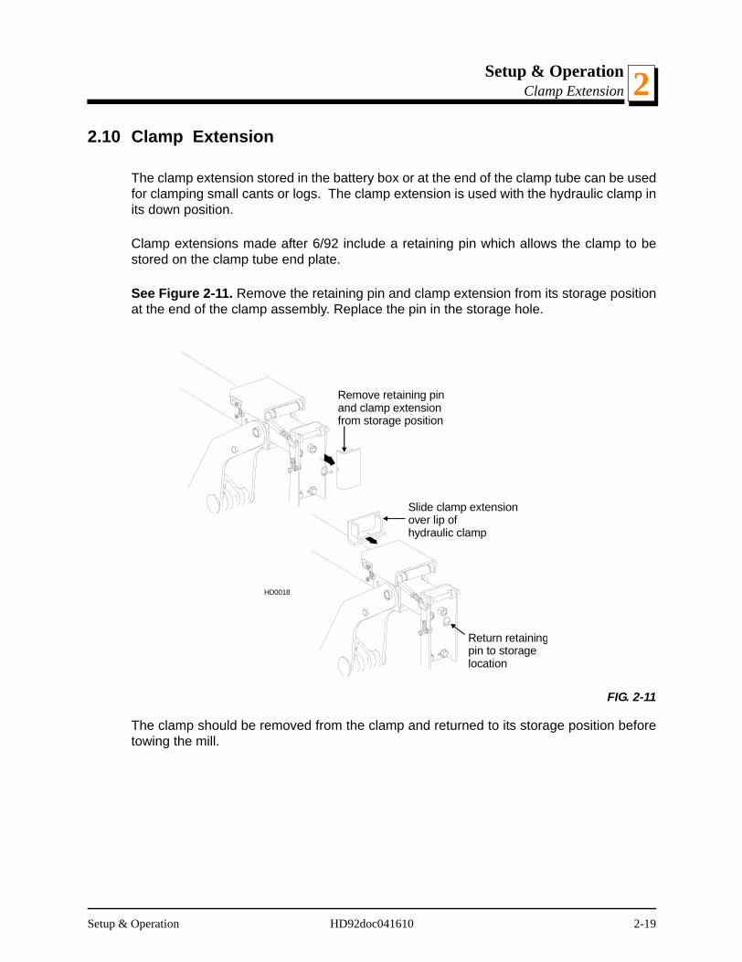
2.10 Clamp Extension
The clamp extension stored in the battery box or at the end of the clamp tube can be usedfor clamping small cants or logs. The clamp extension is used with the hydraulic clamp inits down position.
Clamp extensions made after 6/92 include a retaining pin which allows the clamp to bestored on the clamp tube end plate.
See Figure 2-11. Remove the retaining pin and clamp extension from its storage positionat the end of the clamp assembly. Replace the pin in the storage hole.
The clamp should be removed from the clamp and returned to its storage position beforetowing the mill.
FIG. 2-11
Remove retaining pinand clamp extensionfrom storage position
Slide clamp extensionover lip ofhydraulic clamp
Return retainingpin to storagelocation
HD0018
Setup & Operation HD92doc041610 2-19
Setup & OperationUp/Down Operation2
2.11 Up/Down Operation
1. Install a blade, if needed, and check for correct blade tension. See Section 2.5.
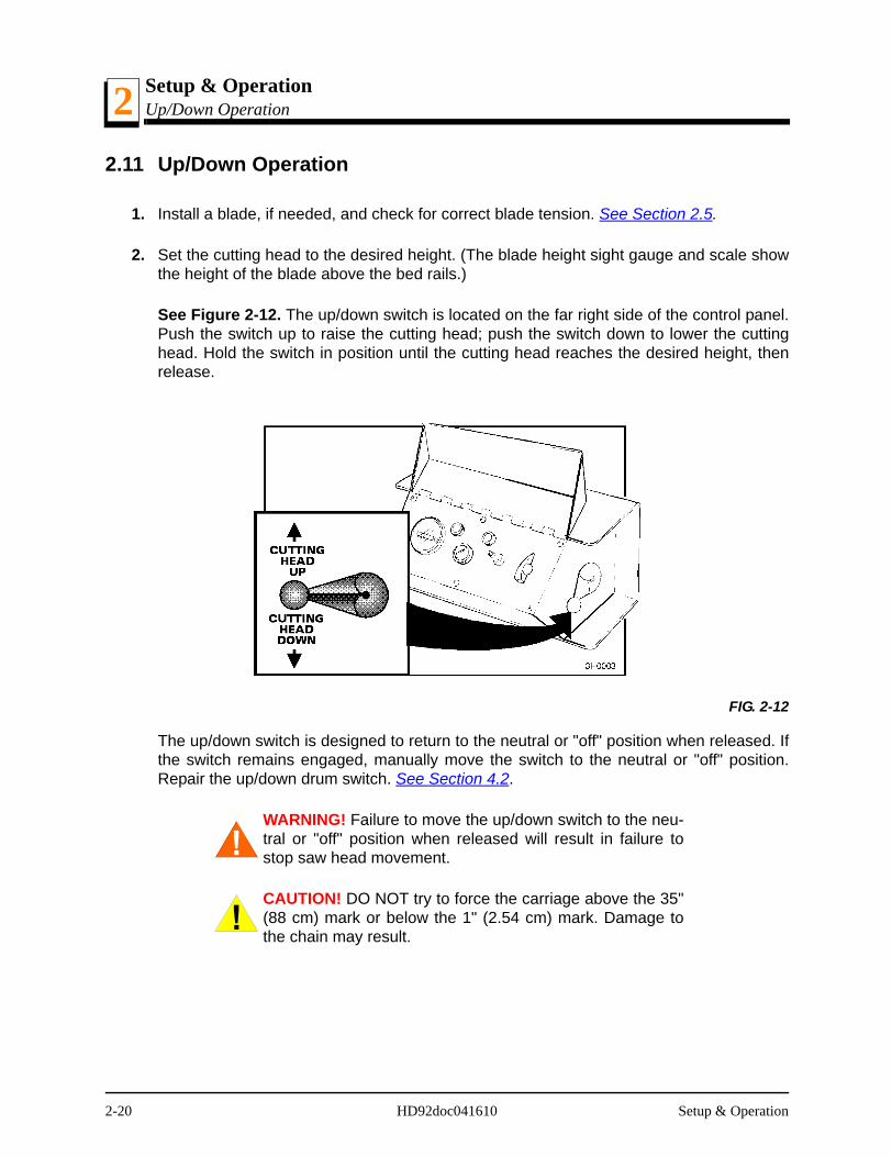
2. Set the cutting head to the desired height. (The blade height sight gauge and scale showthe height of the blade above the bed rails.)
See Figure 2-12. The up/down switch is located on the far right side of the control panel.Push the switch up to raise the cutting head; push the switch down to lower the cuttinghead. Hold the switch in position until the cutting head reaches the desired height, thenrelease.
The up/down switch is designed to return to the neutral or "off" position when released. Ifthe switch remains engaged, manually move the switch to the neutral or "off" position.Repair the up/down drum switch. See Section 4.2.
WARNING! Failure to move the up/down switch to the neu-tral or "off" position when released will result in failure tostop saw head movement.
CAUTION! DO NOT try to force the carriage above the 35"(88 cm) mark or below the 1" (2.54 cm) mark. Damage tothe chain may result.
FIG. 2-12
2-20 HD92doc041610 Setup & Operation
Setup & OperationBlade Guide Arm Operation 2
2.12 Blade Guide Arm Operation
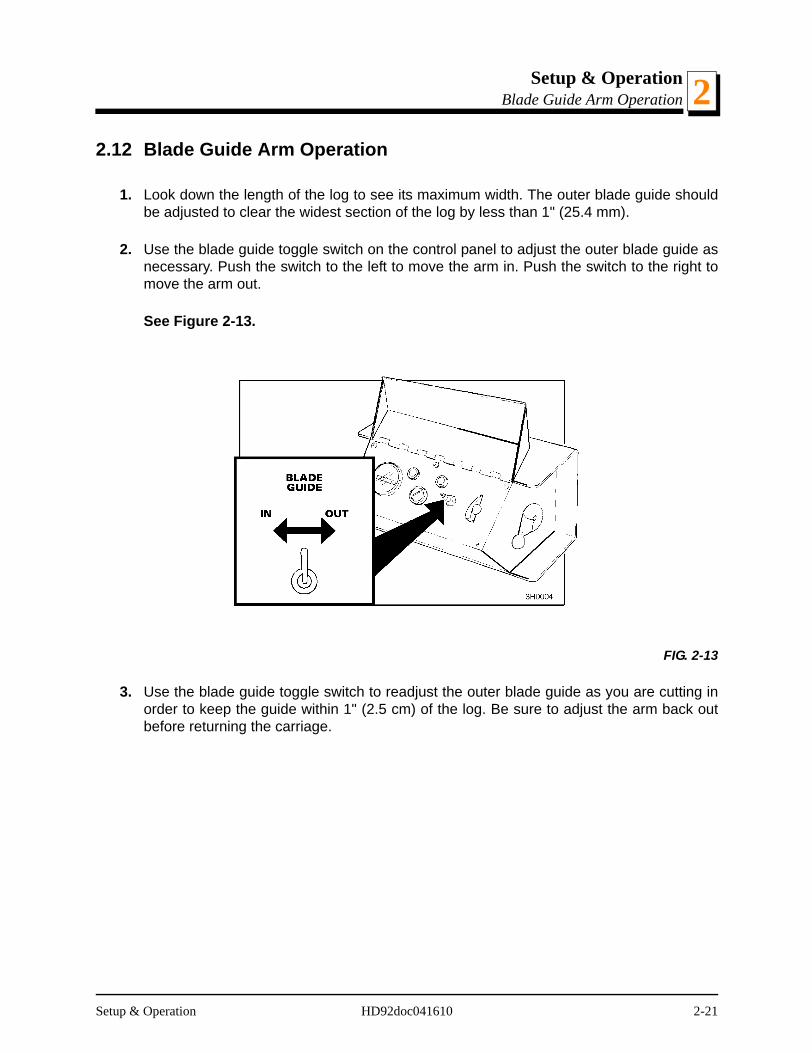
1. Look down the length of the log to see its maximum width. The outer blade guide shouldbe adjusted to clear the widest section of the log by less than 1" (25.4 mm).
2. Use the blade guide toggle switch on the control panel to adjust the outer blade guide asnecessary. Push the switch to the left to move the arm in. Push the switch to the right tomove the arm out.
See Figure 2-13.
3. Use the blade guide toggle switch to readjust the outer blade guide as you are cutting inorder to keep the guide within 1" (2.5 cm) of the log. Be sure to adjust the arm back outbefore returning the carriage.
FIG. 2-13
Setup & Operation HD92doc041610 2-21
Setup & OperationClutch/Brake Operation2
2.13 Clutch/Brake Operation
1. Clear any loose objects from the area of the blade, motor, and drive belt.
2. Make sure the clamp and side supports are adjusted below the level of your first few cuts.
3. Start the engine or motor as instructed in the engine manual.
DANGER! Never operate the sawmill without all guardsand covers in place and secured.
Be sure the blade housing and pulley covers are in placeand secure. If applicable, use the safety retainer pin andcable to fasten blade housing covers.
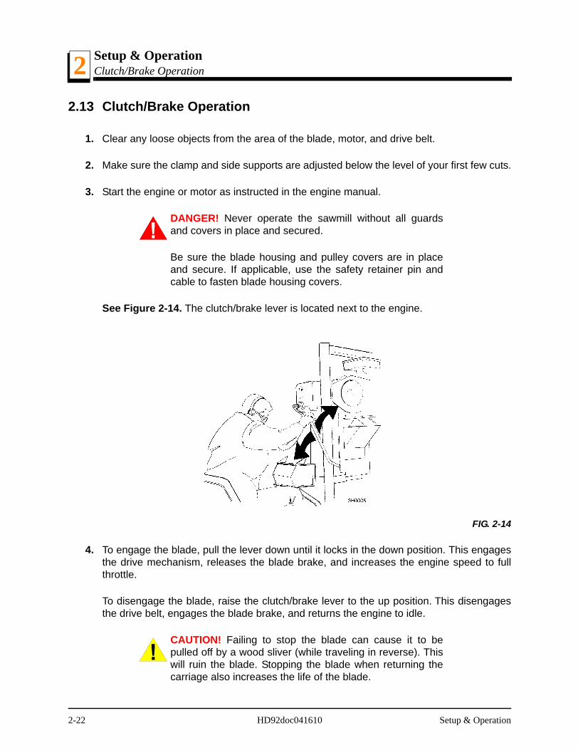
See Figure 2-14. The clutch/brake lever is located next to the engine.
4. To engage the blade, pull the lever down until it locks in the down position. This engagesthe drive mechanism, releases the blade brake, and increases the engine speed to fullthrottle.
To disengage the blade, raise the clutch/brake lever to the up position. This disengagesthe drive belt, engages the blade brake, and returns the engine to idle.
CAUTION! Failing to stop the blade can cause it to bepulled off by a wood sliver (while traveling in reverse). Thiswill ruin the blade. Stopping the blade when returning thecarriage also increases the life of the blade.
FIG. 2-14
2-22 HD92doc041610 Setup & Operation
Setup & OperationPower Feed Operation 2
2.14 Power Feed Operation
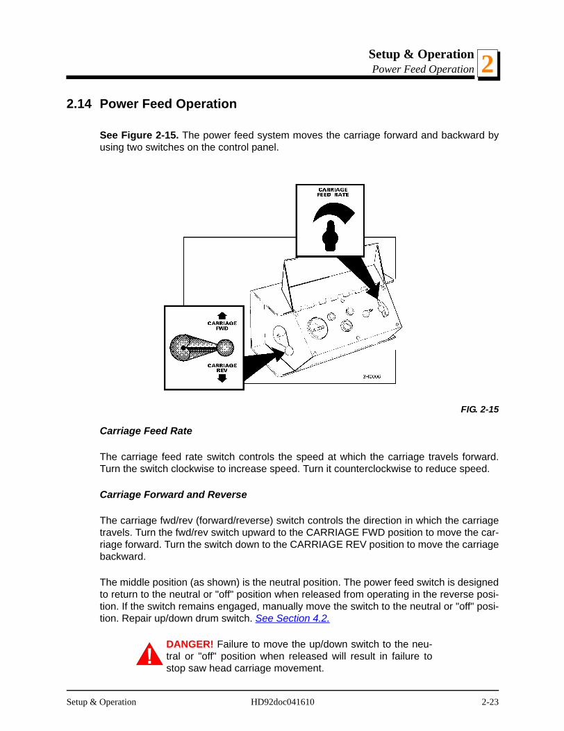
See Figure 2-15. The power feed system moves the carriage forward and backward byusing two switches on the control panel.
Carriage Feed Rate
The carriage feed rate switch controls the speed at which the carriage travels forward.Turn the switch clockwise to increase speed. Turn it counterclockwise to reduce speed.
Carriage Forward and Reverse
The carriage fwd/rev (forward/reverse) switch controls the direction in which the carriagetravels. Turn the fwd/rev switch upward to the CARRIAGE FWD position to move the car-riage forward. Turn the switch down to the CARRIAGE REV position to move the carriagebackward.
The middle position (as shown) is the neutral position. The power feed switch is designedto return to the neutral or "off" position when released from operating in the reverse posi-tion. If the switch remains engaged, manually move the switch to the neutral or "off" posi-tion. Repair up/down drum switch. See Section 4.2.
DANGER! Failure to move the up/down switch to the neu-tral or "off" position when released will result in failure tostop saw head carriage movement.
FIG. 2-15
Setup & Operation HD92doc041610 2-23
Setup & OperationPower Feed Operation2
DANGER! Make sure the carriage fwd/rev switch is in theneutral position before turning the key switch to the on orACC position. This prevents unintended carriage move-ment.
Using The Power Feed
HINT: To get a straight cut in the first part of the board, feed the blade into the log at aslow speed. This stops the blade from flexing and dipping up or down. Turn the carriagefeed rate switch to a slow speed until the whole width of the blade has entered the cut.Then use the carriage feed rate switch to increase the feed rate as desired. Maximumfeed rate varies with width and hardness of the wood. Over-feeding results in engine andblade wear, and also produces a wavy cut.
1. Stop the carriage at the end of the cut by turning the carriage feed rate switch counter-clockwise until the carriage stops moving.
2. Throw the clutch/brake lever UP to stop the blade and drop the engine to idle. Removethe board from the top of the log.
CAUTION! Be sure to stop the blade when returning thecarriage. This will not only prevent the blade from beingpulled off and ruined by a wood sliver, but also will increasethe life of the blade.
3. Return the carriage to the front of the mill by turning the carriage fwd/rev switch DOWN.The power feed motor will bypass the carriage feed rate switch and the carriage will auto-matically return at the fastest speed available. Always disengage the blade beforereturning the carriage for the next cut.
4. Make sure that the blade does not catch on the end of the log. Raise the carriage slightlyto make sure the blade clears the log when returned. HINT: Try to stop the blade while theheel of the blade is still on the log. Then bring the carriage back without adjusting theblade up. This lets you keep the blade at the current height setting so you can make thenext blade height adjustment more quickly.
DANGER! Always keep away from the trailer axle to avoidbeing caught between the axle and moving saw carriage.
2-24 HD92doc041610 Setup & Operation

Setup & OperationCutting The Log 2
2.15 Cutting The Log
The following steps guide you through normal operation of the Wood-Mizer sawmill.
1. Once the log is placed where you want it and clamped firmly turn the key switch to theACC position.
2. Determine where to make your first cut. The sight gauge and the blade height scale willhelp you to do this (See Section 2.17 and See Section 2.18). Set the blade to the desiredheight with the up/down switch. Make sure that the blade will clear all side supports andthe clamp. Adjust the outer blade guide to clear the widest section of the log by movingthe blade guide toggle switch.
3. Make sure all covers and guards are in place. Start the engine. Engage the clutch/brakelever to start the blade spinning.
4. Start the water lube if necessary to prevent sap buildup on the blade. See Section 2.19.
5. Feed the blade into the log slowly (See Section 2.14). Once the blade completely entersthe log, increase the feed rate as desired. Always try to cut at the fastest speed you canwhile keeping an accurate cut. Cutting too slowly will waste blade life and lower produc-tion!
6. As you get to the end of the log, slow down the feed rate. When the teeth exit the end ofthe log, turn the feed rate all the way down and disengage the clutch/brake lever. Removethe slab that you have just cut from the log.
7. Use the carriage fwd/rev switch to return the carriage to the front of the mill. Always dis-engage the blade before returning the carriage for the next cut.
8. Repeat until the first side of the log is cut as desired. Set aside the usable flitches (boardswith bark on one or both sides). You can edge them on the mill later.
9. Lower the toe boards, if they were used. Use the hydraulic levers to release the clampand engage the log turner. Turn the log 90 or 180 degrees. Make sure the flat on the log isplaced flat against side supports if turned 90 degrees. Make sure it is placed on bed railsif turned 180 degrees. If the log was turned 90 degrees and you are using toe boards tocompensate for taper in the log, raise the front or rear toe board again on the second sideof the log until the heart is parallel with the bed.
10. Repeat the steps used to cut the first side of the log until the log is square. Cut boardsfrom the remaining cant by adjusting the blade height for the thickness of boards that youwant.
Example: Remember that the blade cuts a 1/16 - 1/8" (1.6-3.2 mm) wide kerf. If you want1" (25.4 mm) thick boards, lower the carriage 1 1/16 - 1 1/8" (27-28.6 mm) for each board.
Setup & Operation HD92doc041610 2-25

Setup & OperationEdging2
2.16 Edging
The following steps guide you through edging boards on the Wood-Mizer sawmill.
1. Raise the side supports to 1/2 the height of the flitches, or the boards that need to beedged.
2. Stack the flitches on edge against the side supports.
3. Clamp the flitches against the side supports halfway up the flitch height. (Wider flitchesshould be placed to the clamp side. When they are edged, flip them over to edge the sec-ond side without disturbing the other flitches or without having to pull them from the mid-dle of the stack).
4. Adjust the blade height to edge a few of the widest boards.
5. Loosen the clamp and turn the edged boards over to edge the other side.
6. Repeat steps 2-4.
7. Loosen the clamp and remove the boards that have good clean edges on both sides.Clamp the remaining flitches and repeat steps 2-5.
2-26 HD92doc041610 Setup & Operation

Setup & OperationBlade Height Sight Gauge 2
2.17 Blade Height Sight Gauge
See Figure 2-16. The sight gauge is provided on the cutting head carriage to help youdecide where to make the first cuts on a log.
Move the carriage forward until the blade is close to the end of the log.
Position yourself so that your eyes are level with the bottom of the sight gauge spring.With one eye closed, move your head up or down until the bottom of the sight gauge islined up with the bottom of the blade.
Sight down the length of the log. You should be able to see where the blade will passthrough the log down its entire length. Raise or lower the cutting head until you get theblade height you want.
HINT: After judging by eye where you want to make your first slab cut, check the scale.Move the up/down crank to fine-tune the blade height to an even measurement on theblade height scale.
Example: Adjust the blade up to 15" rather than cut at 14 13/16". This will make adjust-ments for the next cuts easier to figure on the scale.
FIG. 2-16
Sight gauge eye-levelwith bottom of blade
SM0047
Setup & Operation HD92doc041610 2-27

Setup & OperationBlade Height Scale2
2.18 Blade Height Scale
See Figure 2-17. The blade height scale is attached to the carriage head frame. Itincludes:
a blade height indicator
an inch scale
a quarter scale
Rev C7-D2: The indicator is attached to the frame and moves up and down with the car-riage head. A retrofit is available so that the indicator remains at eye level and the scalesmove up and down.
Rev D3+: The scales are attached to the frame and move up and down with the carriagehead. The blade indicator, used to read the inch and quarter scales, remains stationary.
FIG. 2-17
15
16
17
18
144
4
4
4
4
5
5
5
5
6
6
6
6
8
8
8
QuarterScale
Blade HeightIndicator
InchScale
3H0007
2-28 HD92doc041610 Setup & Operation

Setup & OperationBlade Height Scale 2
The Inch Scale
The horizontal red line on the blade height indicator shows how many inches the bottomof the blade is above the bed of the mill. If you know the height of your blade at each cut,you can determine the thickness of lumber you are sawing.
Example: You want to cut 1" (25 mm) random width boards from a log. Use the sightgauge to position the blade for the first cut. Move the carriage to an even measurementon the inch scale. Make a trim cut. Return the carriage for the second cut and lower it 11/8" (29 mm) below the original measurement. (The extra 1/8" (3 mm) allows for saw kerfand shrinkage of the lumber.)
Rev. F2+: The scale is shaded. White identifies areas where the blade could encounter aside support or the clamp. Yellow identifies areas where the blade could encounter a sidesupport only.
Setup & Operation HD92doc041610 2-29
Setup & OperationBlade Height Scale2
The Quarter Scale
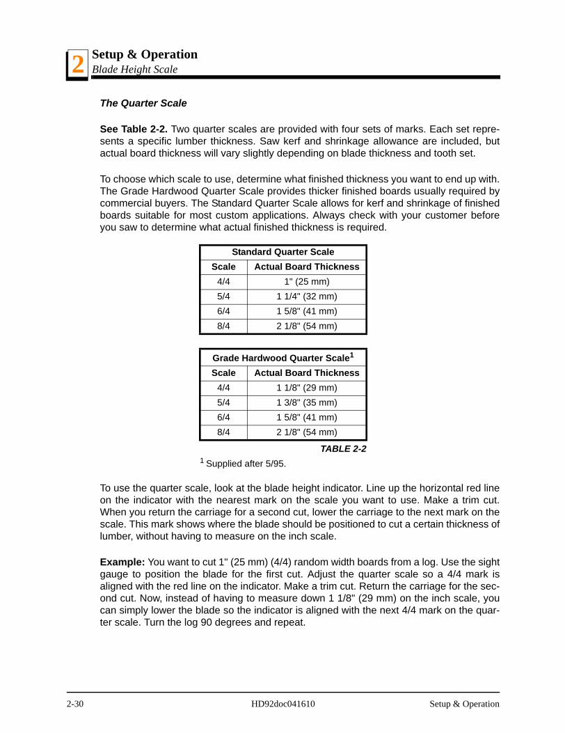
See Table 2-2. Two quarter scales are provided with four sets of marks. Each set repre-sents a specific lumber thickness. Saw kerf and shrinkage allowance are included, butactual board thickness will vary slightly depending on blade thickness and tooth set.
To choose which scale to use, determine what finished thickness you want to end up with.The Grade Hardwood Quarter Scale provides thicker finished boards usually required bycommercial buyers. The Standard Quarter Scale allows for kerf and shrinkage of finishedboards suitable for most custom applications. Always check with your customer beforeyou saw to determine what actual finished thickness is required.
To use the quarter scale, look at the blade height indicator. Line up the horizontal red lineon the indicator with the nearest mark on the scale you want to use. Make a trim cut.When you return the carriage for a second cut, lower the carriage to the next mark on thescale. This mark shows where the blade should be positioned to cut a certain thickness oflumber, without having to measure on the inch scale.
Example: You want to cut 1" (25 mm) (4/4) random width boards from a log. Use the sightgauge to position the blade for the first cut. Adjust the quarter scale so a 4/4 mark isaligned with the red line on the indicator. Make a trim cut. Return the carriage for the sec-ond cut. Now, instead of having to measure down 1 1/8" (29 mm) on the inch scale, youcan simply lower the blade so the indicator is aligned with the next 4/4 mark on the quar-ter scale. Turn the log 90 degrees and repeat.
Standard Quarter ScaleScale Actual Board Thickness
4/4 1" (25 mm)5/4 1 1/4" (32 mm)6/4 1 5/8" (41 mm)8/4 2 1/8" (54 mm)
Grade Hardwood Quarter Scale1
1 Supplied after 5/95.
Scale Actual Board Thickness4/4 1 1/8" (29 mm)5/4 1 3/8" (35 mm)6/4 1 5/8" (41 mm)8/4 2 1/8" (54 mm)
TABLE 2-2
2-30 HD92doc041610 Setup & Operation
Setup & OperationWater Lube Operation 2
2.19 Water Lube Operation
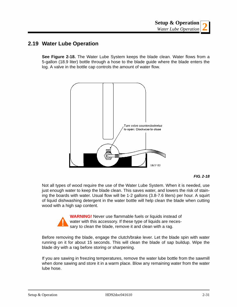
See Figure 2-18. The Water Lube System keeps the blade clean. Water flows from a5-gallon (18.9 liter) bottle through a hose to the blade guide where the blade enters thelog. A valve in the bottle cap controls the amount of water flow.
Not all types of wood require the use of the Water Lube System. When it is needed, usejust enough water to keep the blade clean. This saves water, and lowers the risk of stain-ing the boards with water. Usual flow will be 1-2 gallons (3.8-7.6 liters) per hour. A squirtof liquid dishwashing detergent in the water bottle will help clean the blade when cuttingwood with a high sap content.
WARNING! Never use flammable fuels or liquids instead ofwater with this accessory. If these type of liquids are neces-sary to clean the blade, remove it and clean with a rag.
Before removing the blade, engage the clutch/brake lever. Let the blade spin with waterrunning on it for about 15 seconds. This will clean the blade of sap buildup. Wipe theblade dry with a rag before storing or sharpening.
If you are sawing in freezing temperatures, remove the water lube bottle from the sawmillwhen done sawing and store it in a warm place. Blow any remaining water from the waterlube hose.
FIG. 2-18
Setup & Operation HD92doc041610 2-31
Setup & OperationPreparing The Sawmill For Towing2
2.20 Preparing The Sawmill For Towing
The Wood-Mizer trailer package makes transporting your sawmill easy and convenient.To get your sawmill ready for towing, follow these instructions.
1. Move the saw carriage to the front end of the sawmill. Raise the rear outriggers.
2. Use the hydraulic controls to move the log clamp all the way toward the loading side ofthe mill.
CAUTION! Failure to fully extend the log clamp before tow-ing can result in damage to the clamping assembly duringtowing.
3. Use the hydraulic controls to raise the log turner and loader as high as they will go. Man-ually lift the loader and hook the loader chain to the elbow of the turner. Use the hydraulicturner lever to lower the turner until the chain is tight. Push the loader lever down to bringthe loader arm channels up to the loader.
4. Move the carriage forward to the travel position over the rear bed rail.
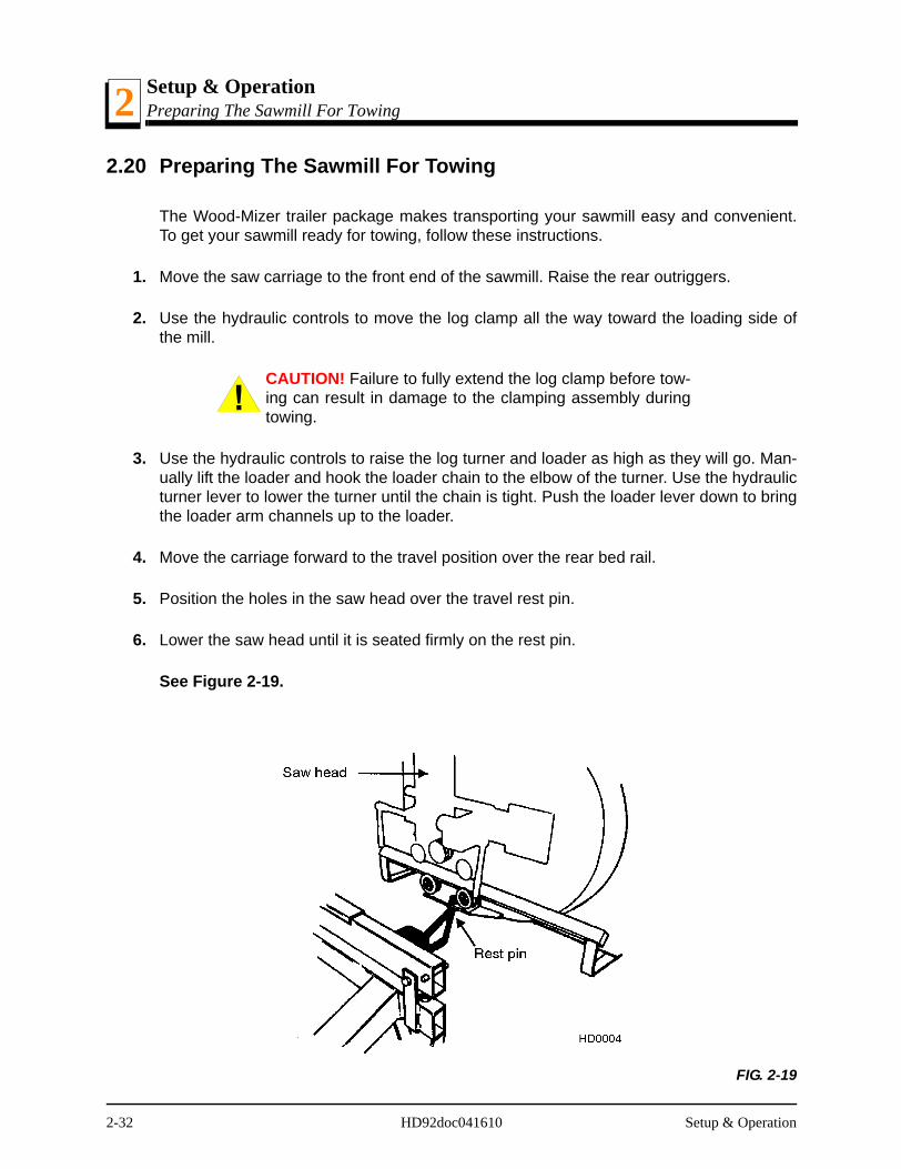
5. Position the holes in the saw head over the travel rest pin.
6. Lower the saw head until it is seated firmly on the rest pin.
See Figure 2-19.
FIG. 2-19
2-32 HD92doc041610 Setup & Operation
Setup & OperationPreparing The Sawmill For Towing 2
7. Continue lowering the head 3/4" (19mm). until it contacts the stop blocks on the mastrails.
CAUTION! Failure to properly secure the saw head canresult in severe machine damage. Lower the saw head ontothe rest pin until it contacts the rest pin collar, then lower thesaw head 3/4" (19mm) further to insure that the saw headcannot be dislocated from the rest pin.
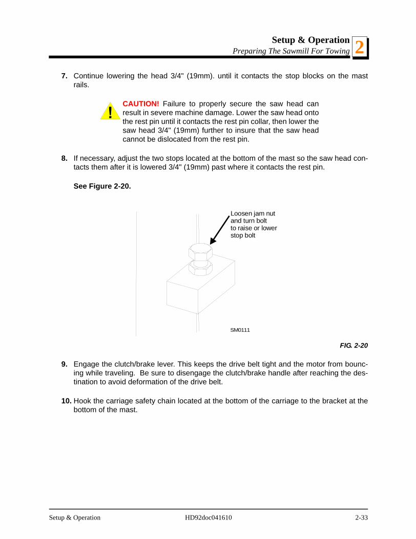
8. If necessary, adjust the two stops located at the bottom of the mast so the saw head con-tacts them after it is lowered 3/4" (19mm) past where it contacts the rest pin.
See Figure 2-20.
9. Engage the clutch/brake lever. This keeps the drive belt tight and the motor from bounc-ing while traveling. Be sure to disengage the clutch/brake handle after reaching the des-tination to avoid deformation of the drive belt.
10. Hook the carriage safety chain located at the bottom of the carriage to the bracket at thebottom of the mast.
FIG. 2-20
Loosen jam nut and turn boltto raise or lowerstop bolt
SM0111
Setup & Operation HD92doc041610 2-33
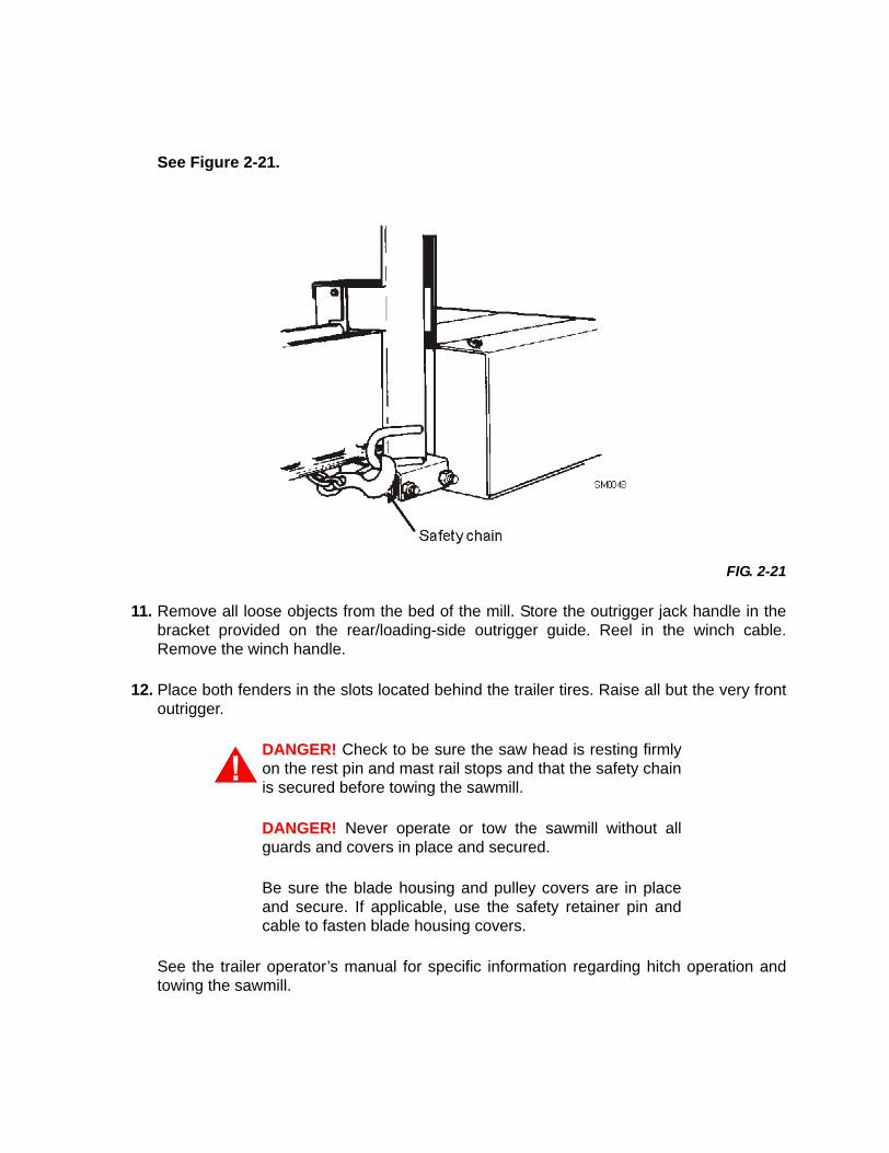
See Figure 2-21.
11. Remove all loose objects from the bed of the mill. Store the outrigger jack handle in thebracket provided on the rear/loading-side outrigger guide. Reel in the winch cable.Remove the winch handle.
12. Place both fenders in the slots located behind the trailer tires. Raise all but the very frontoutrigger.
DANGER! Check to be sure the saw head is resting firmlyon the rest pin and mast rail stops and that the safety chainis secured before towing the sawmill.
DANGER! Never operate or tow the sawmill without allguards and covers in place and secured.
Be sure the blade housing and pulley covers are in placeand secure. If applicable, use the safety retainer pin andcable to fasten blade housing covers.
See the trailer operator’s manual for specific information regarding hitch operation andtowing the sawmill.
FIG. 2-21

MaintenanceWear Life 3
SECTION 3 MAINTENANCE
This section lists the maintenance procedures that need to be performed.
The Short Interval Maintenance Schedule lists procedures that need to be performedevery 4, 8 or 25 hours.The Maintenance Log lists procedures that need to be performedevery 50, 100, 200, 300, 500, or 1000 hours. Keep track of machine maintenance by fill-ing in the machine hours and the date you perform each procedure.
This symbol identifies the interval (hours of operation) at which each maintenance pro-cedure should be performed.
3.1 Wear Life
See Table 3-1. This chart lists estimated life expectancy of common replacement parts ifproper maintenance and operation procedures are followed. Due to the many variableswhich exist during sawmill operation, actual part life may vary significantly. This informa-tion is provided so that you may plan ahead in ordering replacement parts.
Part Description Estimated Life
Up/Down Motor Brushes 375 hoursB57 Blade Wheel Belts 400 hours
Up/Down Motor 750 hoursHydraulic Pump Solenoid 750 hours
Power Feed Motor Brushes
750 hours
Up/Down Drum Switch 1000 hoursBlade Guide Rollers 1000 hours
Hydraulic Pump Motor Brushes
1000 hours
Power Feed Drum Switch 1200 hoursDrive Belt 1250 hours
Power Feed Motor 1500 hoursPower Feed Belt 2000 hours
Up/Down Belt 2000 hours
TABLE 3-1
0
Maintenance HD92doc041610 3-1
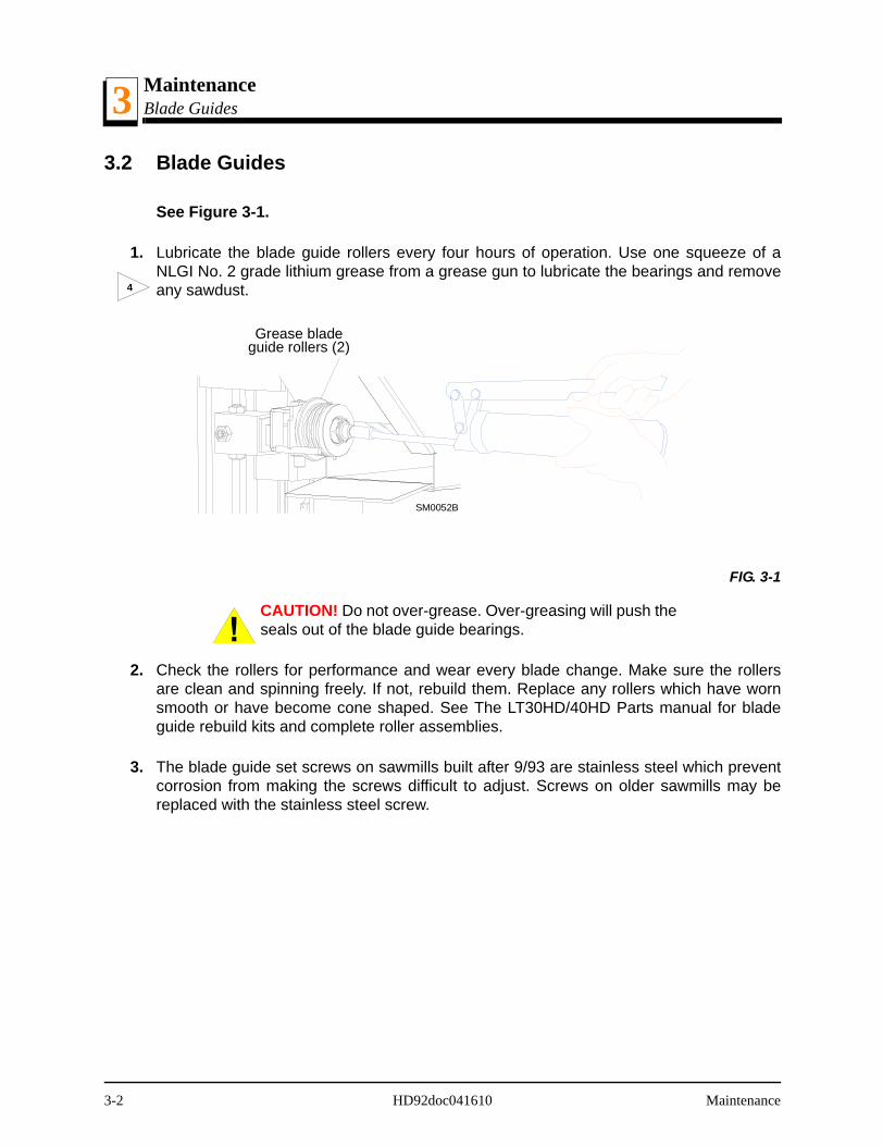
MaintenanceBlade Guides3
3.2 Blade Guides
See Figure 3-1.
1. Lubricate the blade guide rollers every four hours of operation. Use one squeeze of aNLGI No. 2 grade lithium grease from a grease gun to lubricate the bearings and removeany sawdust.
CAUTION! Do not over-grease. Over-greasing will push theseals out of the blade guide bearings.
2. Check the rollers for performance and wear every blade change. Make sure the rollersare clean and spinning freely. If not, rebuild them. Replace any rollers which have wornsmooth or have become cone shaped. See The LT30HD/40HD Parts manual for bladeguide rebuild kits and complete roller assemblies.
3. The blade guide set screws on sawmills built after 9/93 are stainless steel which preventcorrosion from making the screws difficult to adjust. Screws on older sawmills may bereplaced with the stainless steel screw.
FIG. 3-1
4
Grease bladeguide rollers (2)
SM0052B
3-2 HD92doc041610 Maintenance

MaintenanceHydraulic Log Loader 3
3.3 Hydraulic Log Loader
Remove all sawdust and debris from around the velocity fuse valves every 8 hours ofoperation. The valves are located at the bottom of the log loader cylinders.8
Maintenance HD92doc041610 3-3
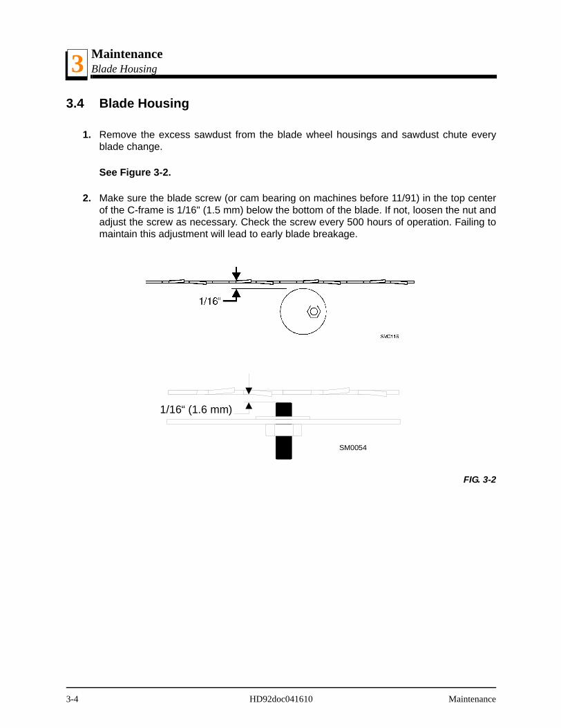
MaintenanceBlade Housing3
3.4 Blade Housing
1. Remove the excess sawdust from the blade wheel housings and sawdust chute everyblade change.
See Figure 3-2.
2. Make sure the blade screw (or cam bearing on machines before 11/91) in the top centerof the C-frame is 1/16" (1.5 mm) below the bottom of the blade. If not, loosen the nut andadjust the screw as necessary. Check the screw every 500 hours of operation. Failing tomaintain this adjustment will lead to early blade breakage.
FIG. 3-2
SM0054
1/16“ (1.6 mm)
3-4 HD92doc041610 Maintenance
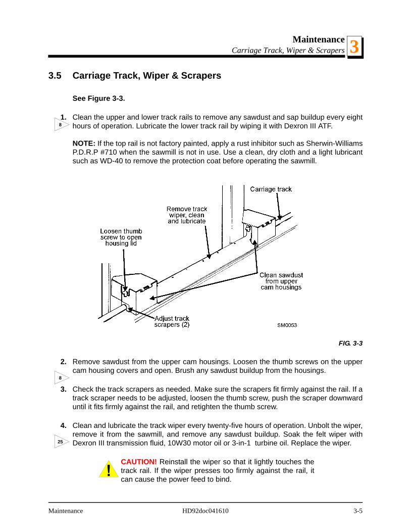
MaintenanceCarriage Track, Wiper & Scrapers 3
3.5 Carriage Track, Wiper & Scrapers
See Figure 3-3.
1. Clean the upper and lower track rails to remove any sawdust and sap buildup every eighthours of operation. Lubricate the lower track rail by wiping it with Dexron III ATF.
NOTE: If the top rail is not factory painted, apply a rust inhibitor such as Sherwin-WilliamsP.D.R.P #710 when the sawmill is not in use. Use a clean, dry cloth and a light lubricantsuch as WD-40 to remove the protection coat before operating the sawmill.
2. Remove sawdust from the upper cam housings. Loosen the thumb screws on the uppercam housing covers and open. Brush any sawdust buildup from the housings.
3. Check the track scrapers as needed. Make sure the scrapers fit firmly against the rail. If atrack scraper needs to be adjusted, loosen the thumb screw, push the scraper downwarduntil it fits firmly against the rail, and retighten the thumb screw.
4. Clean and lubricate the track wiper every twenty-five hours of operation. Unbolt the wiper,remove it from the sawmill, and remove any sawdust buildup. Soak the felt wiper withDexron III transmission fluid, 10W30 motor oil or 3-in-1 turbine oil. Replace the wiper.
CAUTION! Reinstall the wiper so that it lightly touches thetrack rail. If the wiper presses too firmly against the rail, itcan cause the power feed to bind.
FIG. 3-3
8
8
25
Maintenance HD92doc041610 3-5
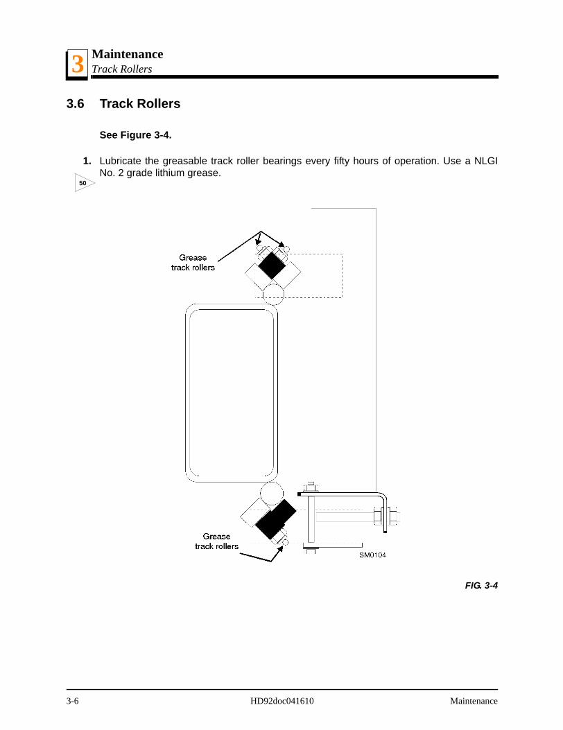
MaintenanceTrack Rollers3
3.6 Track Rollers
See Figure 3-4.
1. Lubricate the greasable track roller bearings every fifty hours of operation. Use a NLGINo. 2 grade lithium grease.
FIG. 3-4
50
3-6 HD92doc041610 Maintenance

MaintenanceVertical Mast Rails 3
3.7 Vertical Mast Rails
Clean and lubricate the vertical mast rails every 50 hours of operation. Clean with solventand remove any rust with a light-grade sand paper or emery cloth. Lubricate the mast withmotor oil or automatic transmission fluid (ATF).
CAUTION! Never use grease on the mast rails as it will col-lect sawdust.
50
Maintenance HD92doc041610 3-7

MaintenanceDrum Switches3
3.8 Drum Switches
Lubricate the up/down and power feed drum switch contacts inside the control panelevery fifty hours of operation. Use only contact grease supplied by Wood-Mizer. Removethe control panel cover. Use a cotton swab to apply grease to the switch contact ends.
WARNING! Drum switch grease contains Petroleum Hydro-carbon Lubricant. Eye and skin irritant. If introduced intoeyes, flush with water for at least 15 minutes. If film or irrita-tion persists, seek medical attention. Wash skin with soapand water. If ingested, do not induce vomiting - contact aphysician. KEEP OUT OF THE REACH OF CHILDREN.
50
3-8 HD92doc041610 Maintenance

MaintenanceMiscellaneous Lubrication 3
3.9 Miscellaneous Lubrication
1. Apply a thin film of a NLGI No. 2 grade lithium grease to the blade guide arm every fiftyhours of operation to help prevent it from rusting.
2. Grease the clamp mechanism, loading arm, and side supports with a NLGI No. 2 gradelithium grease every fifty hours of operation.
3. Oil all chains with Dexron III ATF every fifty hours of operation.
CAUTION! Do not use chain lube. It causes sawdustbuildup in chain links.
50
50
50
Maintenance HD92doc041610 3-9
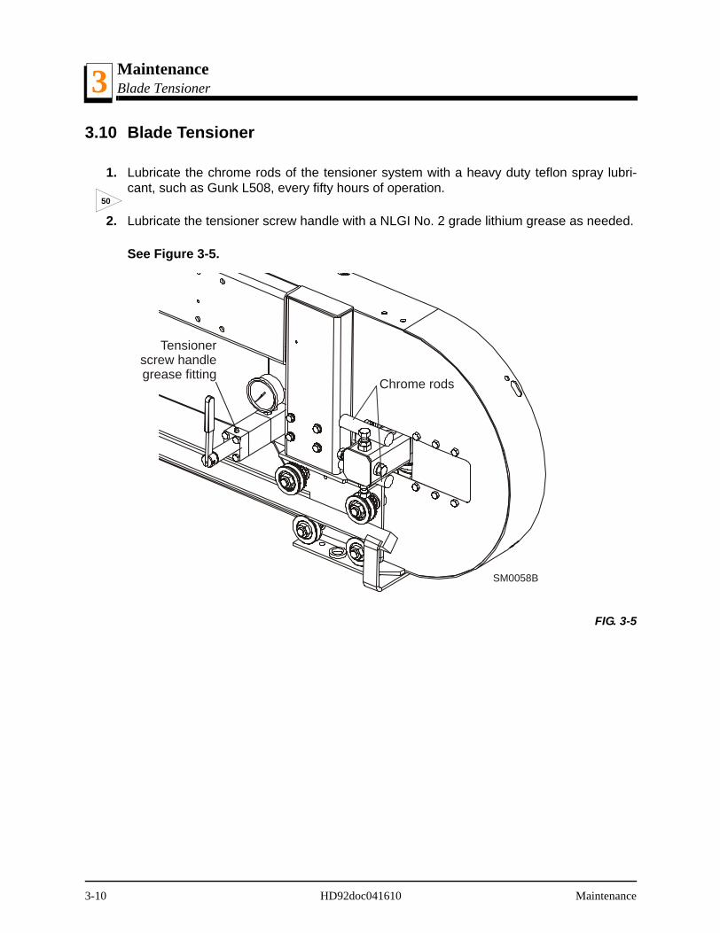
MaintenanceBlade Tensioner3
3.10 Blade Tensioner
1. Lubricate the chrome rods of the tensioner system with a heavy duty teflon spray lubri-cant, such as Gunk L508, every fifty hours of operation.
2. Lubricate the tensioner screw handle with a NLGI No. 2 grade lithium grease as needed.
See Figure 3-5.
FIG. 3-5
50
SM0058B
Chrome rods
Tensionerscrew handlegrease fitting
3-10 HD92doc041610 Maintenance

MaintenanceBlade Wheel Belts 3
3.11 Blade Wheel Belts
1. Rotate the blade wheel belts and check them for wear. Rotating the belts every 50 hourswill give you longer belt life. Replace belts as necessary. Use only B57 belts manufac-tured by Goodyear or Browning.
2. Periodically check all belts for wear. Replace any damaged or worn belts as needed.
50
Maintenance HD92doc041610 3-11
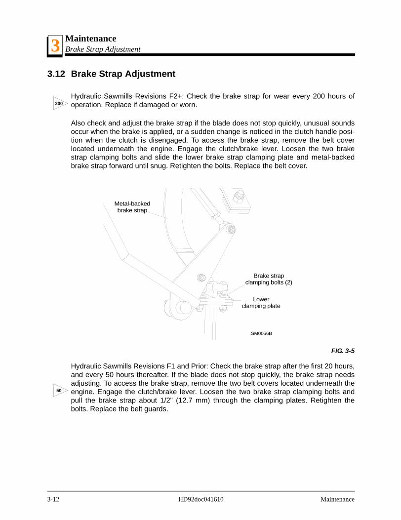
MaintenanceBrake Strap Adjustment3
3.12 Brake Strap Adjustment
Hydraulic Sawmills Revisions F2+: Check the brake strap for wear every 200 hours ofoperation. Replace if damaged or worn.
Also check and adjust the brake strap if the blade does not stop quickly, unusual soundsoccur when the brake is applied, or a sudden change is noticed in the clutch handle posi-tion when the clutch is disengaged. To access the brake strap, remove the belt coverlocated underneath the engine. Engage the clutch/brake lever. Loosen the two brakestrap clamping bolts and slide the lower brake strap clamping plate and metal-backedbrake strap forward until snug. Retighten the bolts. Replace the belt cover.
Hydraulic Sawmills Revisions F1 and Prior: Check the brake strap after the first 20 hours,and every 50 hours thereafter. If the blade does not stop quickly, the brake strap needsadjusting. To access the brake strap, remove the two belt covers located underneath theengine. Engage the clutch/brake lever. Loosen the two brake strap clamping bolts andpull the brake strap about 1/2" (12.7 mm) through the clamping plates. Retighten thebolts. Replace the belt guards.
FIG. 3-5
200
Metal-backedbrake strap
Brake strapclamping bolts (2)
Lowerclamping plate
SM0056B
50
3-12 HD92doc041610 Maintenance

MaintenanceBrake Strap Adjustment 3
See Figure 3-6.
FIG. 3-6
Metal-backedbrake strap
Brake strapclamping bolts (2)
Lowerclamping plate
SM0056B
Maintenance HD92doc041610 3-13
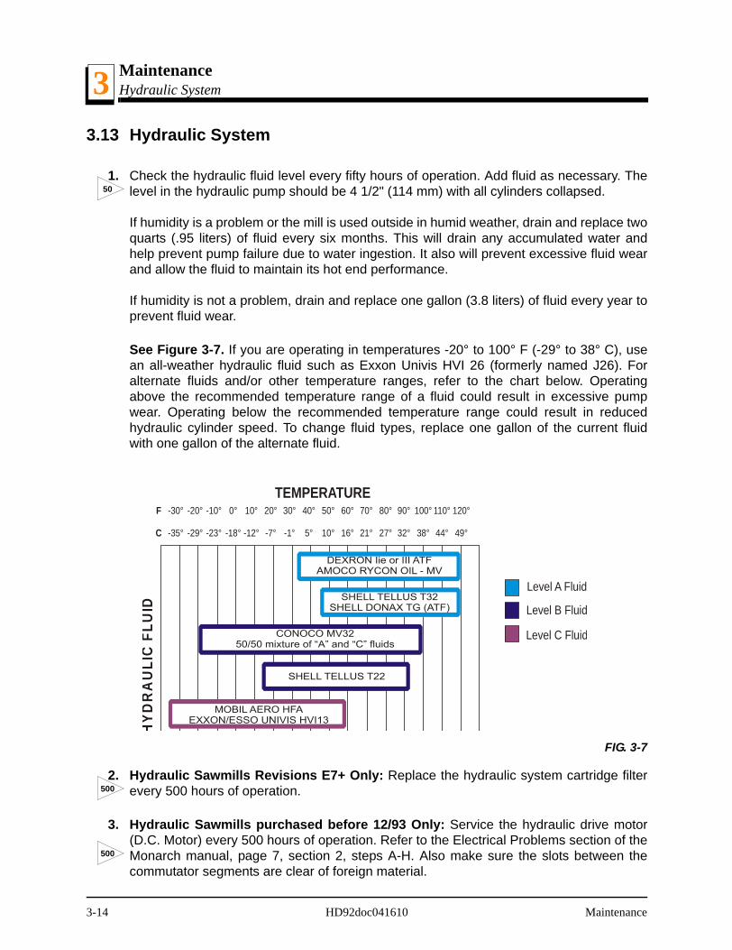
MaintenanceHydraulic System3
3.13 Hydraulic System
1. Check the hydraulic fluid level every fifty hours of operation. Add fluid as necessary. Thelevel in the hydraulic pump should be 4 1/2" (114 mm) with all cylinders collapsed.
If humidity is a problem or the mill is used outside in humid weather, drain and replace twoquarts (.95 liters) of fluid every six months. This will drain any accumulated water andhelp prevent pump failure due to water ingestion. It also will prevent excessive fluid wearand allow the fluid to maintain its hot end performance.
If humidity is not a problem, drain and replace one gallon (3.8 liters) of fluid every year toprevent fluid wear.
See Figure 3-7. If you are operating in temperatures -20° to 100° F (-29° to 38° C), usean all-weather hydraulic fluid such as Exxon Univis HVI 26 (formerly named J26). Foralternate fluids and/or other temperature ranges, refer to the chart below. Operatingabove the recommended temperature range of a fluid could result in excessive pumpwear. Operating below the recommended temperature range could result in reducedhydraulic cylinder speed. To change fluid types, replace one gallon of the current fluidwith one gallon of the alternate fluid.
2. Hydraulic Sawmills Revisions E7+ Only: Replace the hydraulic system cartridge filterevery 500 hours of operation.
3. Hydraulic Sawmills purchased before 12/93 Only: Service the hydraulic drive motor(D.C. Motor) every 500 hours of operation. Refer to the Electrical Problems section of theMonarch manual, page 7, section 2, steps A-H. Also make sure the slots between thecommutator segments are clear of foreign material.
FIG. 3-7
50
120°
49°
40°
5°
80°
27°
0°
-18°
100°
38°
20°
-7°
60°
16°
-20°
-29°
110°
44°
30°
-1°
70°
21°
-10°
-23°
90°
32°
10°
-12°
50°
10°
-30°
-35°
F
C
Level A Fluid
Level B Fluid
Level C Fluid
HYD
RA
ULI
C F
LUID
TEMPERATURE
500
500
3-14 HD92doc041610 Maintenance

MaintenanceHydraulic System 3
To check for excessive end play, as listed in step H, perform the following:
Remove the rear head assembly.
Position (push) the armature shaft to assure that it's drive tab is fully engaged withthe pump shaft slot.
Position (push) the stator frame so it is tight against the pump.
Lay a 6" (15 cm) straightedge across the shaft's exposed bearing journal so it is incontact with the end of the stator's outer wrap.
Measure the gap between the straightedge and the fiber thrust washers locatedagainst the end of the commutator.
Add fiber washers as needed to give a .02 to .05 inch (.51 to 1.27 mm) gap.
Make sure the washer which contacts the end of the commutator is made of steel.
Assemble the rear head assembly to the motor.
4. Periodically check all hydraulic lines and fitting as needed. Replace as necessary.
Maintenance HD92doc041610 3-15
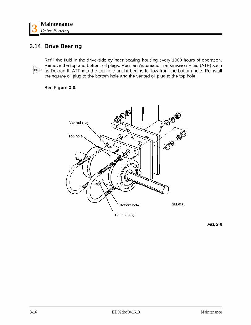
MaintenanceDrive Bearing3
3.14 Drive Bearing
Refill the fluid in the drive-side cylinder bearing housing every 1000 hours of operation.Remove the top and bottom oil plugs. Pour an Automatic Transmission Fluid (ATF) suchas Dexron III ATF into the top hole until it begins to flow from the bottom hole. Reinstallthe square oil plug to the bottom hole and the vented oil plug to the top hole.
See Figure 3-8.
FIG. 3-8
1000
3-16 HD92doc041610 Maintenance
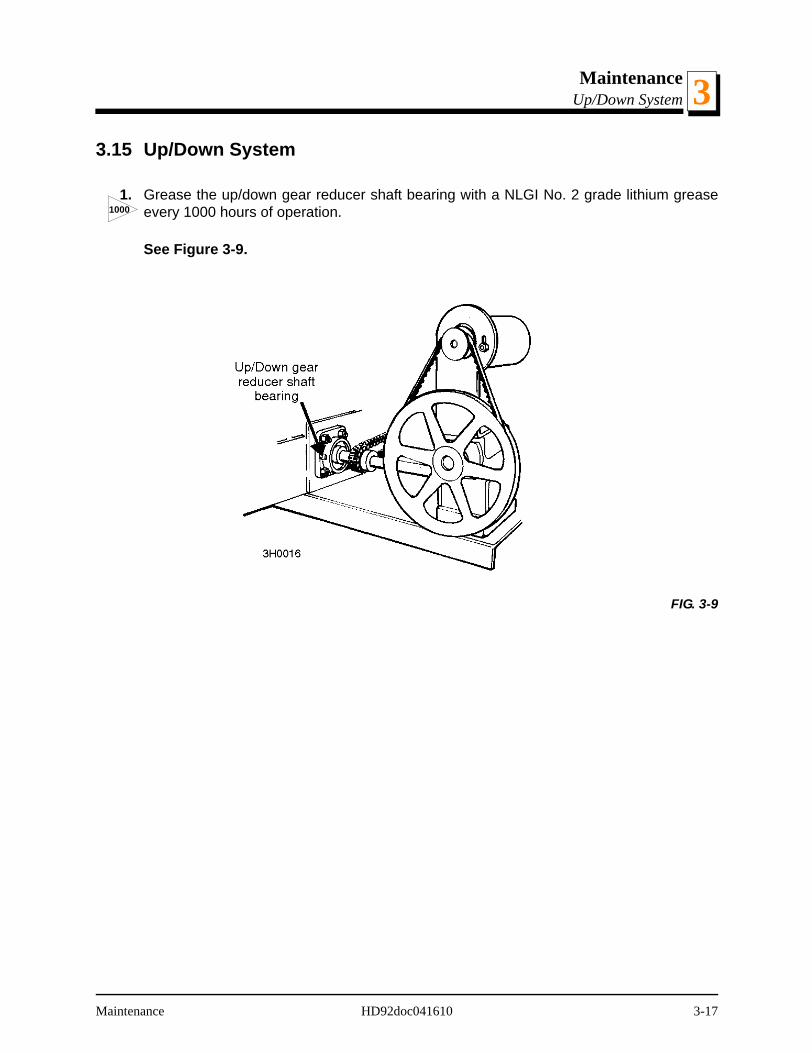
MaintenanceUp/Down System 3
3.15 Up/Down System
1. Grease the up/down gear reducer shaft bearing with a NLGI No. 2 grade lithium greaseevery 1000 hours of operation.
See Figure 3-9.
FIG. 3-9
1000
Maintenance HD92doc041610 3-17
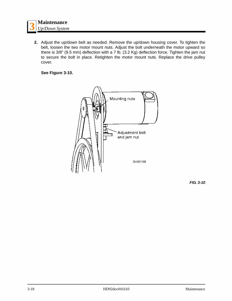
MaintenanceUp/Down System3
2. Adjust the up/down belt as needed. Remove the up/down housing cover. To tighten thebelt, loosen the two motor mount nuts. Adjust the bolt underneath the motor upward sothere is 3/8" (9.5 mm) deflection with a 7 lb. (3.2 Kg) deflection force. Tighten the jam nutto secure the bolt in place. Retighten the motor mount nuts. Replace the drive pulleycover.
See Figure 3-10.
FIG. 3-10
3-18 HD92doc041610 Maintenance
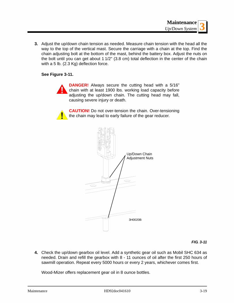
MaintenanceUp/Down System 3
3. Adjust the up/down chain tension as needed. Measure chain tension with the head all theway to the top of the vertical mast. Secure the carriage with a chain at the top. Find thechain adjusting bolt at the bottom of the mast, behind the battery box. Adjust the nuts onthe bolt until you can get about 1 1/2" (3.8 cm) total deflection in the center of the chainwith a 5 lb. (2.3 Kg) deflection force.
See Figure 3-11.
DANGER! Always secure the cutting head with a 5/16”chain with at least 1900 lbs. working load capacity beforeadjusting the up/down chain. The cutting head may fall,causing severe injury or death.
CAUTION! Do not over-tension the chain. Over-tensioningthe chain may lead to early failure of the gear reducer.
4. Check the up/down gearbox oil level. Add a synthetic gear oil such as Mobil SHC 634 asneeded. Drain and refill the gearbox with 8 - 11 ounces of oil after the first 250 hours ofsawmill operation. Repeat every 5000 hours or every 2 years, whichever comes first.
Wood-Mizer offers replacement gear oil in 8 ounce bottles.
FIG. 3-11
Up/Down ChainAdjustment Nuts
3H0020B
Maintenance HD92doc041610 3-19
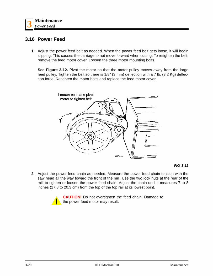
MaintenancePower Feed3
3.16 Power Feed
1. Adjust the power feed belt as needed. When the power feed belt gets loose, it will beginslipping. This causes the carriage to not move forward when cutting. To retighten the belt,remove the feed motor cover. Loosen the three motor mounting bolts.
See Figure 3-12. Pivot the motor so that the motor pulley moves away from the largefeed pulley. Tighten the belt so there is 1/8" (3 mm) deflection with a 7 lb. (3.2 Kg) deflec-tion force. Retighten the motor bolts and replace the feed motor cover.
2. Adjust the power feed chain as needed. Measure the power feed chain tension with thesaw head all the way toward the front of the mill. Use the two lock nuts at the rear of themill to tighten or loosen the power feed chain. Adjust the chain until it measures 7 to 8inches (17.8 to 20.3 cm) from the top of the top rail at its lowest point.
CAUTION! Do not overtighten the feed chain. Damage tothe power feed motor may result.
FIG. 3-12
3-20 HD92doc041610 Maintenance
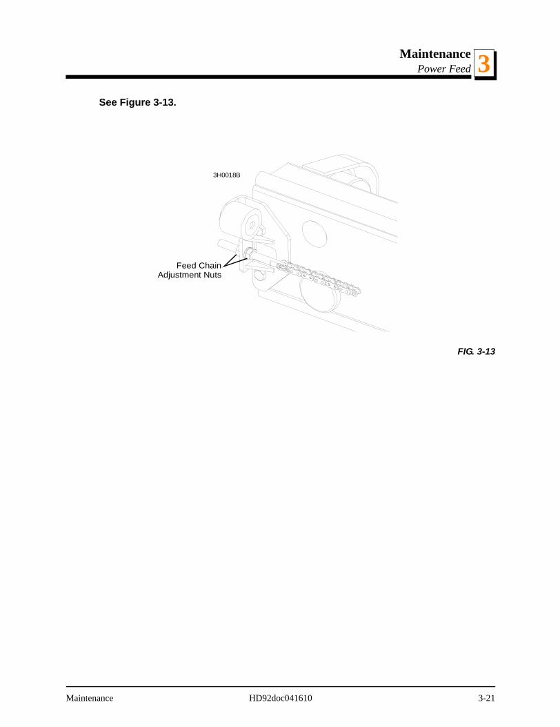
MaintenancePower Feed 3
See Figure 3-13.
FIG. 3-13
Feed ChainAdjustment Nuts
3H0018B
Maintenance HD92doc041610 3-21

MaintenanceMiscellaneous Maintenance3
3.17 Miscellaneous Maintenance
1. Check the mill alignment every setup. See Section 5, Alignment.
2. Make sure all safety warning decals are readable. Remove sawdust and dirt. Replace anydamaged or unreadable decals immediately. Order decals from your Customer ServiceRepresentative.
WARNING! Keep all safety warning decals clean and visi-ble. If decal becomes worn or damaged, replace immedi-ately.
3. Check all battery and fuse box connections are tight and free of corrosion. In 7/93, thefuse block assembly was upgraded to prevent connections from coming loose and over-heating. The fuse block can be retrofitted to LT30HD/40HD rev D3-E2.
3-22 HD92doc041610 Maintenance
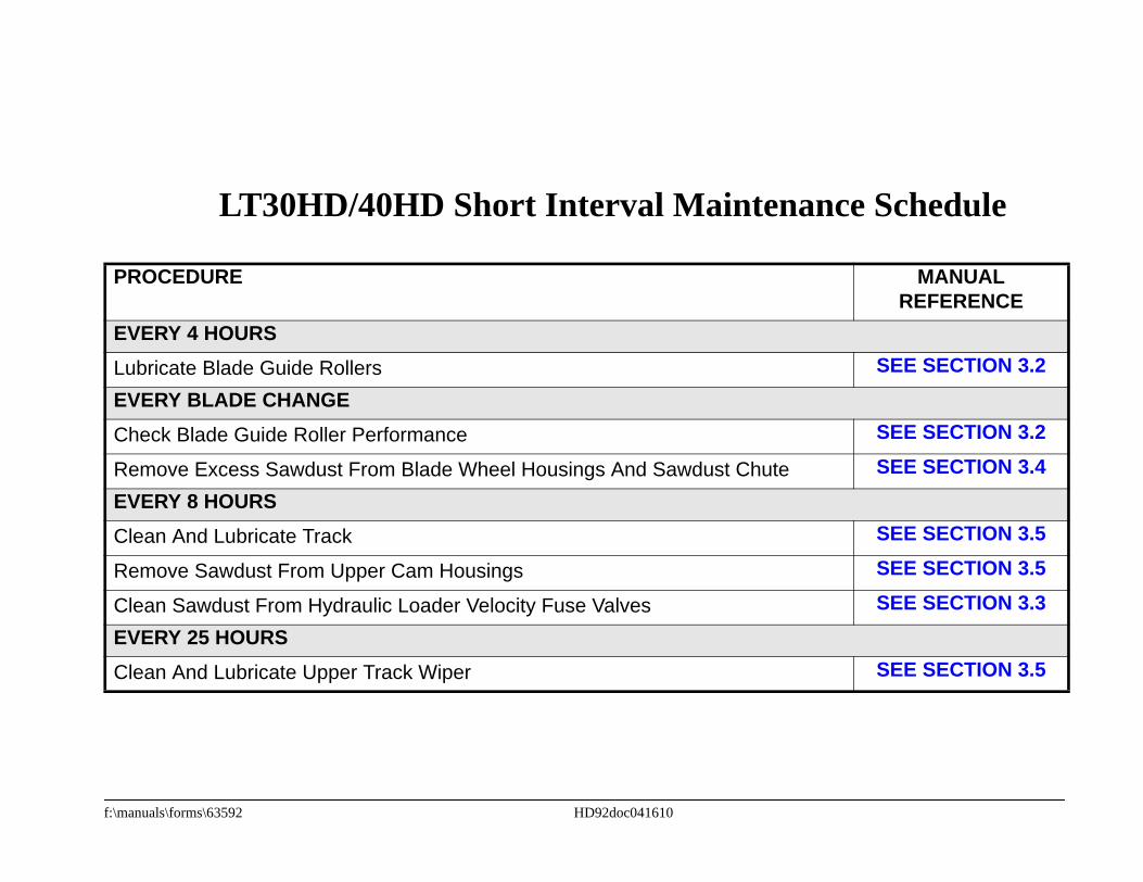
ance Schedule
MANUALREFERENCE
SEE SECTION 3.2
SEE SECTION 3.2SEE SECTION 3.4
SEE SECTION 3.5SEE SECTION 3.5SEE SECTION 3.3
SEE SECTION 3.5
LT30HD/40HD Short Interval Mainten
PROCEDURE
EVERY 4 HOURSLubricate Blade Guide RollersEVERY BLADE CHANGECheck Blade Guide Roller Performance
Remove Excess Sawdust From Blade Wheel Housings And Sawdust ChuteEVERY 8 HOURSClean And Lubricate Track
Remove Sawdust From Upper Cam Housings
Clean Sawdust From Hydraulic Loader Velocity Fuse ValvesEVERY 25 HOURSClean And Lubricate Upper Track Wiper
f:\manuals\forms\63592 HD92doc041610


f:\manu
LOG
S OF OPERATIONURS AS YOU PERFORM EACH PROCEDURE.NANCE IS NOT NEEDED AT THIS TIME.
300 HRS 350 HRS 400 HRS 450 HRS 500 HRS
Clean
Greas
Lubric
Greas
Check
Check
Rotatewear
Check
Check
Lubric
Inspec
Check
Check
Repla
Servic
Repla
Greas
als\forms\624 HD92doc041610
WOOD-MIZER LT30HD/LT40HD MAINTENANCE
PROCEDURE MANUALREFERENCE
TOTAL HOURFILL IN THE DATE AND THE MACHINE HO
A SHADED BOX INDICATES MAINTE50 HRS 100 HRS 150 HRS 200 HRS 25O HRS
& lube mast rails See Section 3.7
e track rollers (If greasable rollers) See Section 3.6
ate drum switches See Section 3.8
e pivot points and bearings/Oil chains See Section 3.9See Section 3.15See Section 3.16
belt tensions See Section 3.15See Section 3.16
brake strap tension See Section 3.12
drive/idle blade wheel belts/Check all belts for See Section 3.11
feed & up/down chain tensions See Section 3.15See Section 3.16
up/down gear box fluid level See Section 3.15
ate blade tensioner handle and rods See Section 3.10
t hydraulic lines & fittings See Section 3.13
hydraulic fluid level See Section 3.13
blade screw (or cam bearing) See Section 3.4
ce hydraulic system filter (Rev E7+) See Section 3.13
e Hydraulic Drive Motor (Rev C7 - E6) See Section 3.13
ce cylinder drive bearing fluid See Section 3.14
e up/down shaft bearing See Section 3.15

f:\manu
LOG
S OF OPERATIONURS AS YOU PERFORM EACH PROCEDURE.NANCE IS NOT NEEDED AT THIS TIME.
800 HRS 850 HRS 900 HRS 950 HRS 1000 HRS
Clean
Greas
Lubric
Greas
Check
Check
Rotatewear
Check
Check
Lubric
Inspec
Check
Check
Repla
Servic
Repla
Greas
als\forms\624 HD92doc041610
WOOD-MIZER LT30HD/LT40HD MAINTENANCE
PROCEDURE MANUALREFERENCE
TOTAL HOURFILL IN THE DATE AND THE MACHINE HO
A SHADED BOX INDICATES MAINTE550 HRS 600 HRS 650 HRS 700 HRS 75O HRS
& lube mast rails See Section 3.7
e track rollers (If greasable rollers) See Section 3.6
ate drum switches See Section 3.8
e pivot points and bearings/Oil chains See Section 3.9See Section 3.15See Section 3.16
belt tensions See Section 3.15See Section 3.16
brake strap tension See Section 3.12
drive/idle blade wheel belts/Check all belts for See Section 3.11
feed & up/down chain tensions See Section 3.15See Section 3.16
up/down gear box fluid level See Section 3.15
ate blade tensioner handle and rods See Section 3.10
t hydraulic lines & fittings See Section 3.13
hydraulic fluid level See Section 3.13
blade screw (or cam bearing) See Section 3.4
ce hydraulic system filter (Rev E7+) See Section 3.13
e Hydraulic Drive Motor (Rev C7 - E6) See Section 3.13
ce cylinder drive bearing fluid See Section 3.14
e up/down shaft bearing See Section 3.15

f:\manu
LOG
S OF OPERATIONURS AS YOU PERFORM EACH PROCEDURE.NANCE IS NOT NEEDED AT THIS TIME.
1300 HRS 1350 HRS 1400 HRS 1450 HRS 1500 HRS
Clean
Greas
Lubric
Greas
Check
Check
Rotatewear
Check
Check
Lubric
Inspec
Check
Check
Repla
Servic
Repla
Greas
als\forms\624 HD92doc041610
]
WOOD-MIZER LT30HD/LT40HD MAINTENANCE
PROCEDURE MANUALREFERENCE
TOTAL HOURFILL IN THE DATE AND THE MACHINE HO
A SHADED BOX INDICATES MAINTE1050 HRS 1100 HRS 1150 HRS 1200 HRS 125O HRS
& lube mast rails See Section 3.7
e track rollers (If greasable rollers) See Section 3.6
ate drum switches See Section 3.8
e pivot points and bearings/Oil chains See Section 3.9See Section 3.15See Section 3.16
belt tensions See Section 3.15See Section 3.16
brake strap tension See Section 3.12
drive/idle blade wheel belts/Check all belts for See Section 3.11
feed & up/down chain tensions See Section 3.15See Section 3.16
up/down gear box fluid level See Section 3.15
ate blade tensioner handle and rods See Section 3.10
t hydraulic lines & fittings See Section 3.13
hydraulic fluid level See Section 3.13
blade screw (or cam bearing) See Section 3.4
ce hydraulic system filter (Rev E7+) See Section 3.13
e Hydraulic Drive Motor (Rev C7 - E6) See Section 3.13
ce cylinder drive bearing fluid See Section 3.14
e up/down shaft bearing See Section 3.15

f:\manu
LOG
S OF OPERATIONURS AS YOU PERFORM EACH PROCEDURE.NANCE IS NOT NEEDED AT THIS TIME.
1800 HRS 1850 HRS 1900 HRS 1950 HRS 2000 HRS
Clean
Greas
Lubric
Greas
Check
Check
Rotatewear
Check
Check
Lubric
Inspec
Check
Check
Repla
Servic
Repla
Greas
als\forms\624 HD92doc041610
WOOD-MIZER LT30HD/LT40HD MAINTENANCE
PROCEDURE MANUALREFERENCE
TOTAL HOURFILL IN THE DATE AND THE MACHINE HO
A SHADED BOX INDICATES MAINTE1550 HRS 1600 HRS 1650 HRS 1700 HRS 175O HRS
& lube mast rails See Section 3.7
e track rollers (If greasable rollers) See Section 3.6
ate drum switches See Section 3.8
e pivot points and bearings/Oil chains See Section 3.9See Section 3.15See Section 3.16
belt tensions See Section 3.15See Section 3.16
brake strap tension See Section 3.12
drive/idle blade wheel belts/Check all belts for See Section 3.11
feed & up/down chain tensions See Section 3.15See Section 3.16
up/down gear box fluid level See Section 3.15
ate blade tensioner handle and rods See Section 3.10
t hydraulic lines & fittings See Section 3.13
hydraulic fluid level See Section 3.13
blade screw (or cam bearing) See Section 3.4
ce hydraulic system filter (Rev E7+) See Section 3.13
e Hydraulic Drive Motor (Rev C7 - E6) See Section 3.13
ce cylinder drive bearing fluid See Section 3.14
e up/down shaft bearing See Section 3.15

f:\manu
LOG
S OF OPERATIONURS AS YOU PERFORM EACH PROCEDURE.NANCE IS NOT NEEDED AT THIS TIME.
2300 HRS 2350 HRS 2400 HRS 2450 HRS 2500 HRS
Clean
Greas
Lubric
Greas
Check
Check
Rotatewear
Check
Check
Lubric
Inspec
Check
Check
Repla
Servic
Repla
Greas
als\forms\624 HD92doc041610
WOOD-MIZER LT30HD/LT40HD MAINTENANCE
PROCEDURE MANUALREFERENCE
TOTAL HOURFILL IN THE DATE AND THE MACHINE HO
A SHADED BOX INDICATES MAINTE2050 HRS 2100 HRS 2150 HRS 2200 HRS 225O HRS
& lube mast rails See Section 3.7
e track rollers (If greasable rollers) See Section 3.6
ate drum switches See Section 3.8
e pivot points and bearings/Oil chains See Section 3.9See Section 3.15See Section 3.16
belt tensions See Section 3.15See Section 3.16
brake strap tension See Section 3.12
drive/idle blade wheel belts/Check all belts for See Section 3.11
feed & up/down chain tensions See Section 3.15See Section 3.16
up/down gear box fluid level See Section 3.15
ate blade tensioner handle and rods See Section 3.10
t hydraulic lines & fittings See Section 3.13
hydraulic fluid level See Section 3.13
blade screw (or cam bearing) See Section 3.4
ce hydraulic system filter (Rev E7+) See Section 3.13
e Hydraulic Drive Motor (Rev C7 - E6) See Section 3.13
ce cylinder drive bearing fluid See Section 3.14
e up/down shaft bearing See Section 3.15

f:\manu
LOG
S OF OPERATIONURS AS YOU PERFORM EACH PROCEDURE.NANCE IS NOT NEEDED AT THIS TIME.
2800 HRS 2850 HRS 2900 HRS 2950 HRS 3000 HRS
Clean
Greas
Lubric
Greas
Check
Check
Rotatewear
Check
Check
Lubric
Inspec
Check
Check
Repla
Servic
Repla
Greas
als\forms\624 HD92doc041610
WOOD-MIZER LT30HD/LT40HD MAINTENANCE
PROCEDURE MANUALREFERENCE
TOTAL HOURFILL IN THE DATE AND THE MACHINE HO
A SHADED BOX INDICATES MAINTE2550 HRS 2600 HRS 2650 HRS 2700 HRS 275O HRS
& lube mast rails See Section 3.7
e track rollers (If greasable rollers) See Section 3.6
ate drum switches See Section 3.8
e pivot points and bearings/Oil chains See Section 3.9See Section 3.15See Section 3.16
belt tensions See Section 3.15See Section 3.16
brake strap tension See Section 3.12
drive/idle blade wheel belts/Check all belts for See Section 3.11
feed & up/down chain tensions See Section 3.15See Section 3.16
up/down gear box fluid level See Section 3.15
ate blade tensioner handle and rods See Section 3.10
t hydraulic lines & fittings See Section 3.13
hydraulic fluid level See Section 3.13
blade screw (or cam bearing) See Section 3.4
ce hydraulic system filter (Rev E7+) See Section 3.13
e Hydraulic Drive Motor (Rev C7 - E6) See Section 3.13
ce cylinder drive bearing fluid See Section 3.14
e up/down shaft bearing See Section 3.15
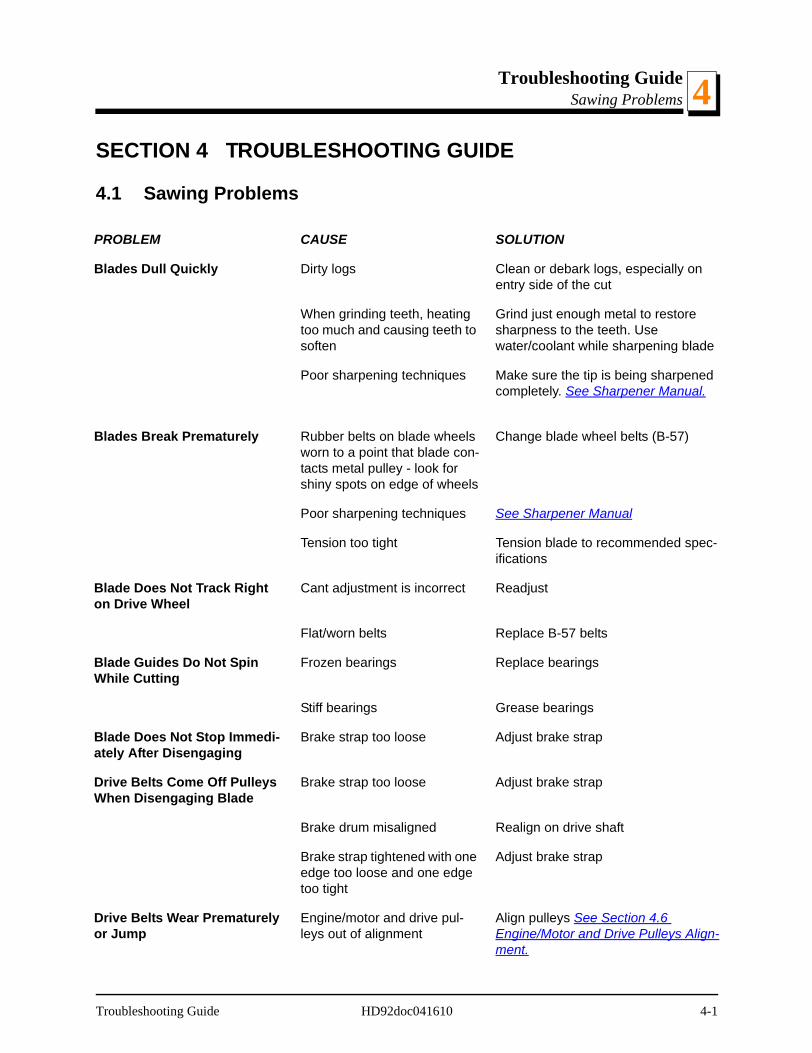
Troubleshooting GuideSawing Problems 4
SECTION 4 TROUBLESHOOTING GUIDE
4.1 Sawing Problems
PROBLEM CAUSE SOLUTION
Blades Dull Quickly Dirty logs Clean or debark logs, especially on entry side of the cut
When grinding teeth, heating too much and causing teeth to soften
Grind just enough metal to restore sharpness to the teeth. Use water/coolant while sharpening blade
Poor sharpening techniques Make sure the tip is being sharpened completely. See Sharpener Manual.
Blades Break Prematurely Rubber belts on blade wheels worn to a point that blade con-tacts metal pulley - look for shiny spots on edge of wheels
Change blade wheel belts (B-57)
Poor sharpening techniques See Sharpener Manual
Tension too tight Tension blade to recommended spec-ifications
Blade Does Not Track Right on Drive Wheel
Cant adjustment is incorrect Readjust
Flat/worn belts Replace B-57 belts
Blade Guides Do Not Spin While Cutting
Frozen bearings Replace bearings
Stiff bearings Grease bearings
Blade Does Not Stop Immedi-ately After Disengaging
Brake strap too loose Adjust brake strap
Drive Belts Come Off Pulleys When Disengaging Blade
Brake strap too loose Adjust brake strap
Brake drum misaligned Realign on drive shaft
Brake strap tightened with one edge too loose and one edge too tight
Adjust brake strap
Drive Belts Wear Prematurely or Jump
Engine/motor and drive pul-leys out of alignment
Align pulleys See Section 4.6 Engine/Motor and Drive Pulleys Align-ment.
Troubleshooting Guide HD92doc041610 4-1
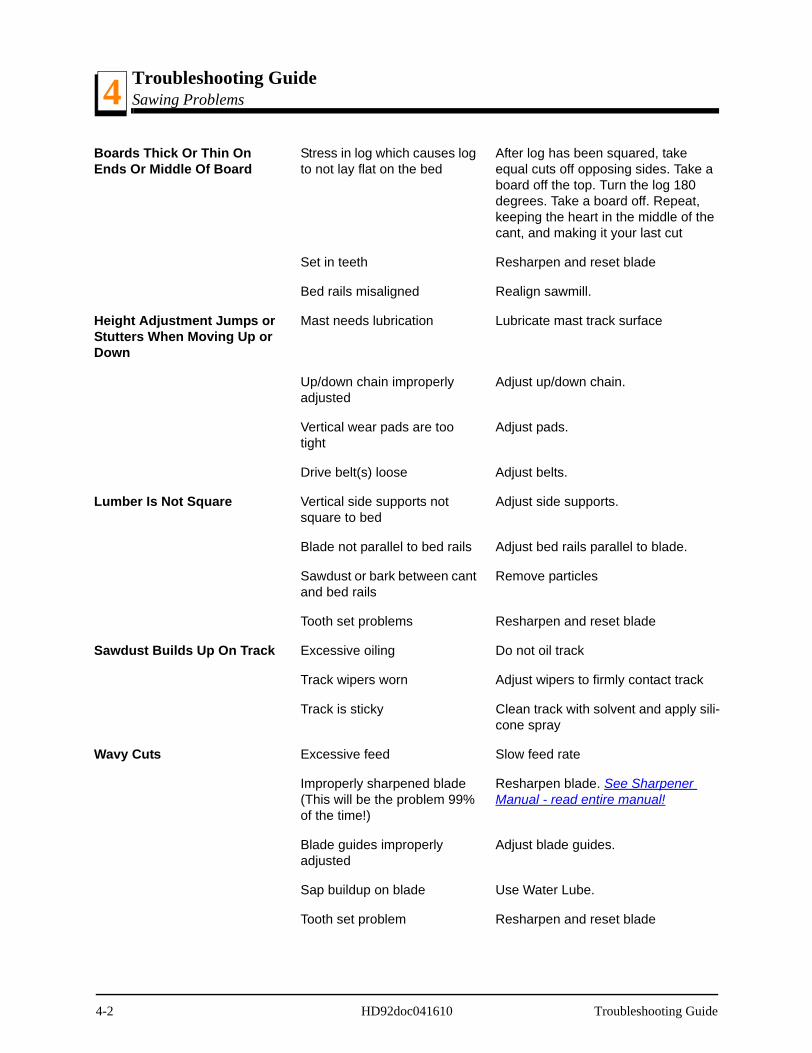
Troubleshooting GuideSawing Problems4
Boards Thick Or Thin On Ends Or Middle Of Board
Stress in log which causes log to not lay flat on the bed
After log has been squared, take equal cuts off opposing sides. Take a board off the top. Turn the log 180 degrees. Take a board off. Repeat, keeping the heart in the middle of the cant, and making it your last cut
Set in teeth Resharpen and reset blade
Bed rails misaligned Realign sawmill.
Height Adjustment Jumps or Stutters When Moving Up or Down
Mast needs lubrication Lubricate mast track surface
Up/down chain improperly adjusted
Adjust up/down chain.
Vertical wear pads are too tight
Adjust pads.
Drive belt(s) loose Adjust belts.
Lumber Is Not Square Vertical side supports not square to bed
Adjust side supports.
Blade not parallel to bed rails Adjust bed rails parallel to blade.
Sawdust or bark between cant and bed rails
Remove particles
Tooth set problems Resharpen and reset blade
Sawdust Builds Up On Track Excessive oiling Do not oil track
Track wipers worn Adjust wipers to firmly contact track
Track is sticky Clean track with solvent and apply sili-cone spray
Wavy Cuts Excessive feed Slow feed rate
Improperly sharpened blade (This will be the problem 99% of the time!)
Resharpen blade. See Sharpener Manual - read entire manual!
Blade guides improperly adjusted
Adjust blade guides.
Sap buildup on blade Use Water Lube.
Tooth set problem Resharpen and reset blade
4-2 HD92doc041610 Troubleshooting Guide
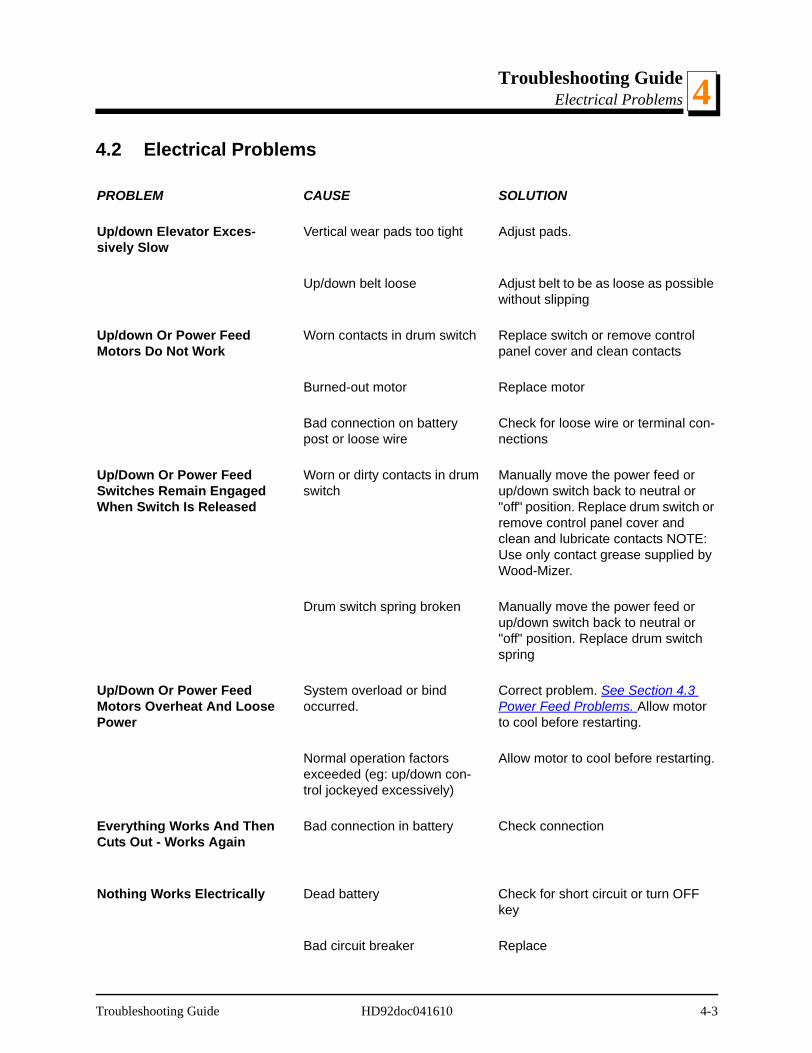
Troubleshooting GuideElectrical Problems 4
4.2 Electrical Problems
PROBLEM CAUSE SOLUTION
Up/down Elevator Exces-sively Slow
Vertical wear pads too tight Adjust pads.
Up/down belt loose Adjust belt to be as loose as possible without slipping
Up/down Or Power Feed Motors Do Not Work
Worn contacts in drum switch Replace switch or remove control panel cover and clean contacts
Burned-out motor Replace motor
Bad connection on battery post or loose wire
Check for loose wire or terminal con-nections
Up/Down Or Power Feed Switches Remain Engaged When Switch Is Released
Worn or dirty contacts in drum switch
Manually move the power feed or up/down switch back to neutral or "off" position. Replace drum switch or remove control panel cover and clean and lubricate contacts NOTE: Use only contact grease supplied by Wood-Mizer.
Drum switch spring broken Manually move the power feed or up/down switch back to neutral or "off" position. Replace drum switch spring
Up/Down Or Power Feed Motors Overheat And Loose Power
System overload or bind occurred.
Correct problem. See Section 4.3 Power Feed Problems. Allow motor to cool before restarting.
Normal operation factors exceeded (eg: up/down con-trol jockeyed excessively)
Allow motor to cool before restarting.
Everything Works And Then Cuts Out - Works Again
Bad connection in battery Check connection
Nothing Works Electrically Dead battery Check for short circuit or turn OFF key
Bad circuit breaker Replace
Troubleshooting Guide HD92doc041610 4-3
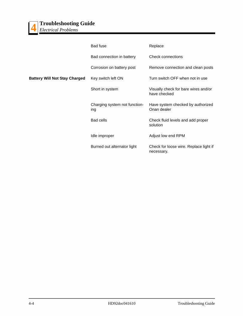
Troubleshooting GuideElectrical Problems4
Bad fuse Replace
Bad connection in battery Check connections
Corrosion on battery post Remove connection and clean posts
Battery Will Not Stay Charged Key switch left ON Turn switch OFF when not in use
Short in system Visually check for bare wires and/or have checked
Charging system not function-ing
Have system checked by authorized Onan dealer
Bad cells Check fluid levels and add proper solution
Idle improper Adjust low end RPM
Burned out alternator light Check for loose wire. Replace light if necessary.
4-4 HD92doc041610 Troubleshooting Guide
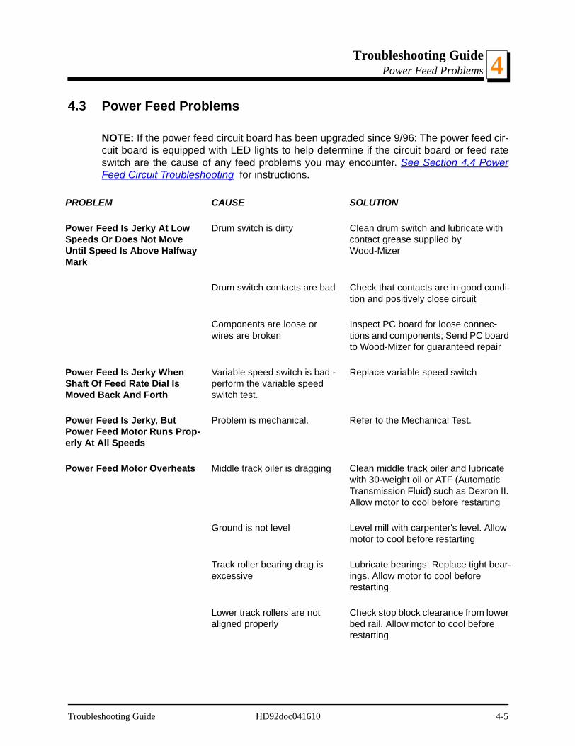
Troubleshooting GuidePower Feed Problems 4
4.3 Power Feed Problems
NOTE: If the power feed circuit board has been upgraded since 9/96: The power feed cir-cuit board is equipped with LED lights to help determine if the circuit board or feed rateswitch are the cause of any feed problems you may encounter. See Section 4.4 PowerFeed Circuit Troubleshooting for instructions.
PROBLEM CAUSE SOLUTION
Power Feed Is Jerky At Low Speeds Or Does Not Move Until Speed Is Above Halfway Mark
Drum switch is dirty Clean drum switch and lubricate with contact grease supplied by Wood-Mizer
Drum switch contacts are bad Check that contacts are in good condi-tion and positively close circuit
Components are loose or wires are broken
Inspect PC board for loose connec-tions and components; Send PC board to Wood-Mizer for guaranteed repair
Power Feed Is Jerky When Shaft Of Feed Rate Dial Is Moved Back And Forth
Variable speed switch is bad - perform the variable speed switch test.
Replace variable speed switch
Power Feed Is Jerky, But Power Feed Motor Runs Prop-erly At All Speeds
Problem is mechanical. Refer to the Mechanical Test.
Power Feed Motor Overheats Middle track oiler is dragging Clean middle track oiler and lubricate with 30-weight oil or ATF (Automatic Transmission Fluid) such as Dexron II. Allow motor to cool before restarting
Ground is not level Level mill with carpenter's level. Allow motor to cool before restarting
Track roller bearing drag is excessive
Lubricate bearings; Replace tight bear-ings. Allow motor to cool before restarting
Lower track rollers are not aligned properly
Check stop block clearance from lower bed rail. Allow motor to cool before restarting
Troubleshooting Guide HD92doc041610 4-5
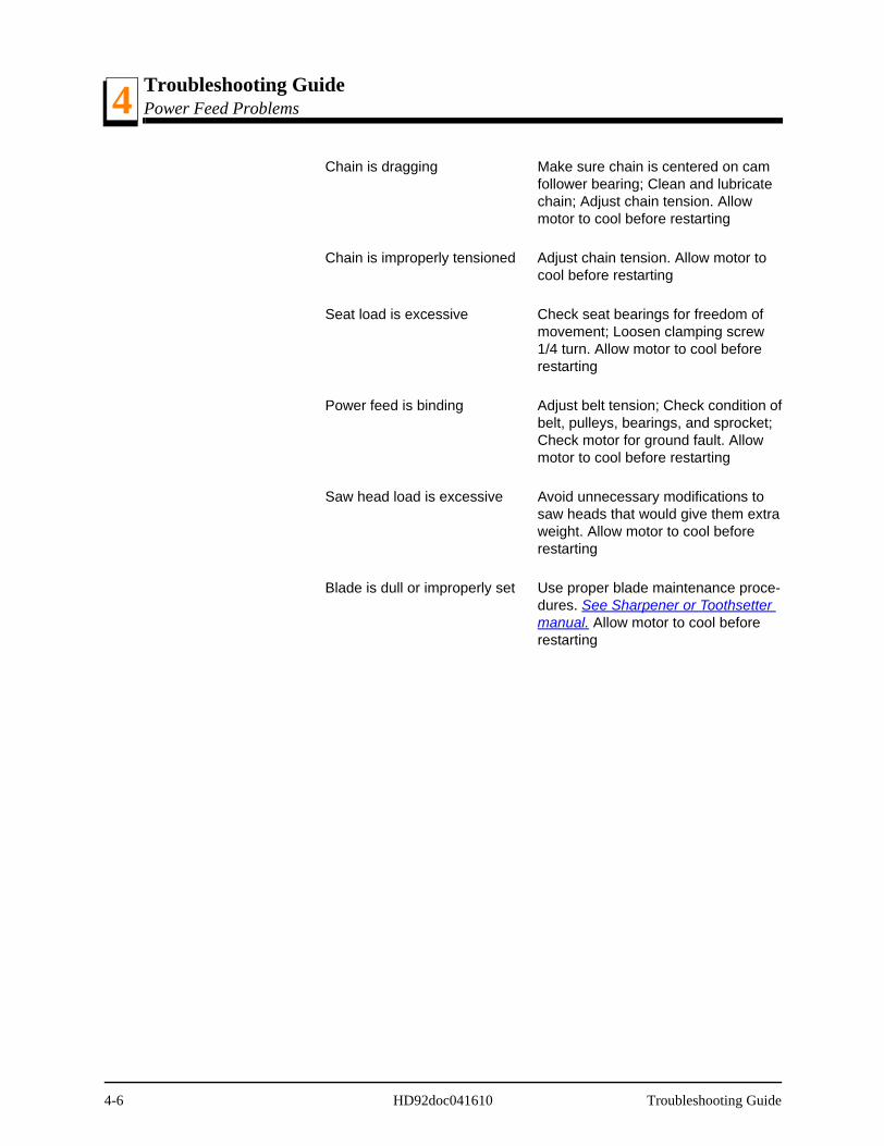
Troubleshooting GuidePower Feed Problems4
Chain is dragging Make sure chain is centered on cam follower bearing; Clean and lubricate chain; Adjust chain tension. Allow motor to cool before restarting
Chain is improperly tensioned Adjust chain tension. Allow motor to cool before restarting
Seat load is excessive Check seat bearings for freedom of movement; Loosen clamping screw 1/4 turn. Allow motor to cool before restarting
Power feed is binding Adjust belt tension; Check condition of belt, pulleys, bearings, and sprocket; Check motor for ground fault. Allow motor to cool before restarting
Saw head load is excessive Avoid unnecessary modifications to saw heads that would give them extra weight. Allow motor to cool before restarting
Blade is dull or improperly set Use proper blade maintenance proce-dures. See Sharpener or Toothsetter manual. Allow motor to cool before restarting
4-6 HD92doc041610 Troubleshooting Guide
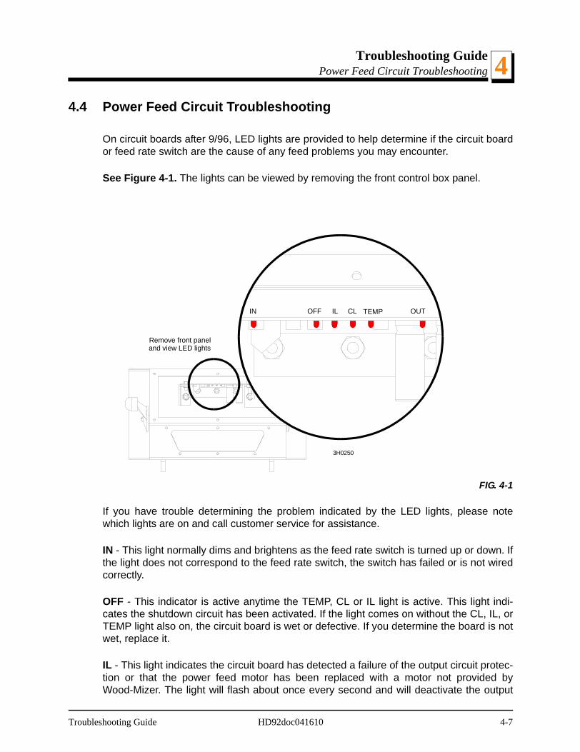
Troubleshooting GuidePower Feed Circuit Troubleshooting 4
4.4 Power Feed Circuit Troubleshooting
On circuit boards after 9/96, LED lights are provided to help determine if the circuit boardor feed rate switch are the cause of any feed problems you may encounter.
See Figure 4-1. The lights can be viewed by removing the front control box panel.
If you have trouble determining the problem indicated by the LED lights, please notewhich lights are on and call customer service for assistance.
IN - This light normally dims and brightens as the feed rate switch is turned up or down. Ifthe light does not correspond to the feed rate switch, the switch has failed or is not wiredcorrectly.
OFF - This indicator is active anytime the TEMP, CL or IL light is active. This light indi-cates the shutdown circuit has been activated. If the light comes on without the CL, IL, orTEMP light also on, the circuit board is wet or defective. If you determine the board is notwet, replace it.
IL - This light indicates the circuit board has detected a failure of the output circuit protec-tion or that the power feed motor has been replaced with a motor not provided byWood-Mizer. The light will flash about once every second and will deactivate the output
FIG. 4-1
3H0250
IN OFF
Remove front paneland view LED lights
IL CL TEMP OUT
Troubleshooting Guide HD92doc041610 4-7

Troubleshooting GuidePower Feed Circuit Troubleshooting4
circuit. If the power feed motor is a Wood-Mizer replacement, replace the circuit board.
CL - This light indicates an extreme overload condition of the power feed motor or a shortin the wiring between the motor and circuit board. The light will flash about once everysecond and deactivate the feed system until the problem is corrected.
TEMP - When lit, this light indicates the temperature of the output circuit is too high andwill shut off the circuit. Once the circuit cools, the light will go off and the feed will becomeoperational. Temperatures become too high when the power feed motor is overloaded.
OUT - This light normally dims and brightens at the same rate as the IN light when thefeed rate switch is turned up and down. If the OUT light does not correspond with the INlight, replace the circuit board.
4-8 HD92doc041610 Troubleshooting Guide
Troubleshooting GuideHydraulic Problems 4
4.5 Hydraulic Problems
PROBLEM CAUSE SOLUTION
You Can Actuate Any Hydrau-lic Handle, But Get No Response From The Pump.
Carriage not positioned prop-erly to provide power to the pump
Move carriage so that contacts touch. Make sure carriage contact bracket is adjusted far enough forward to touch contact on main tube. Check contacts for tarnish or loose wires
Defective solenoid (may be indicated by solenoid clicking) See Monarch manual for trou-bleshooting solenoid
Tapping on solenoid may fix tempo-rarily. Replace solenoid. NOTE: The solenoid is not a standard automotive type. Order from Monarch or Wood-Mizer only
Low or dead battery Test battery. Replace or recharge as necessary
Defective pump motor Remove motor from pump and inspect. Repair or replace as neces-sary
Poor ground connection Check ground connection between pump and saw frame
You Can Get Response From the Pump By Actuating All But One or Two Handles (Revisions E7+ Only)
Valve assembly switch con-tacts are not properly adjusted
Locate the valve switch at the bottom of the valve assembly. Use a 3MM allen wrench to loosen the set screw on each of the five switch contacts. Press each contact to the valve block and tighten the contact set screw to secure in place. CAUTION! Do not overtighten!
NOTE: Do not adjust the valve switch or switch spring; they have been pre-set at the factory.
You Can Get Response From The Pump By Actuating All But One Handle (Revisions C7 - E6 Only)
Electric contact spring inside of non-working valve cor-roded, broken, or dislocated
Check contact spring. Relocate or replace as necessary
Set screw holding handle to valve shaft is loose
Tighten set screw so that valve shaft turns when handle is actuated
Troubleshooting Guide HD92doc041610 4-9
Troubleshooting GuideHydraulic Problems4
Pump Motor Runs With Little Or No Response From The Cylinders
Low battery Test battery. Recharge or replace as necessary
Debris clogging pressure relief valve (Revisions C7 - E6 Only)
Clean pressure relief valve. See Mon-arch manual.
Low fluid level Check fluid level. Add an all-season hydraulic fluid such as Amoco Rycon Oil MV or Mobil Multipurpose ATF (automatic transmission fluid)until level is 4 - 4 1/2" from bottom of reservoir with all cylinders retracted
Pressure relief valve moved from proper setting
Adjust pressure relief valve.
Low air temperature causing fluid to thicken
Allow fluid to warm up. Synthetic flu-ids are available that allow for hydrau-lic operation in cold weather conditions (Univis HVI 13)
Pump Motor Runs Continu-ously When Power Contact Is Made
Solenoid is stuck closed Tapping the solenoid may solve this problem temporarily. Replace sole-noid
Valve handle spring is deformed or broken, causing the handle to not return to the neutral position (Revisions C7 - E6 Only)
Replace handle spring
Contact spring is dislocated and lying across contacts (Revisions C7 - E6 Only)
Replace contact spring
Fluid Leaks From Around Cyl-inder Piston Ram
Worn seals Replace seals in cylinder. Check pis-ton ram for abrasive weld that may be causing premature seal failure
4-10 HD92doc041610 Troubleshooting Guide
Troubleshooting GuideHydraulic Problems 4
Fluid Leak Around Pump Box Loose seal or fitting Wipe pump off completely to locate cause of lead. You may have to unbolt the pump to wipe behind it. NOTE: Movement of the sawmill can cause fluid to slosh up into the foam filter in the reservoir cap, and subse-quently spray out, giving the appear-ance that fluid is leaking from the pump
Hydraulic Side Supports Go Down Before Or At Same Time As Log Turner
Dirt in sequence valve Remove sequence valves and clean thoroughly with kerosene. NOTE: Be sure to reassemble the valve and install it in its original position on the cylinder
Retainer in sequence valve worn
Replace sequence valve
Low air temperature causing fluid to thicken
Allow fluid to warm up. Synthetic flu-ids are available that allow for hydrau-lic operation in cold weather conditions (Univis HVI 13)
Hydraulic Turner Goes Up Before Or At Same Time As Side Supports
Spring weakening in sequence valve
Locate sequence valve at top of turner cylinder. Turn heavy spring in about 1/4 turn
Dirt in sequence valve Remove sequence valves and clean thoroughly with kerosene. NOTE: Be sure to reassemble the valve and install it in its original position on the cylinder
Retainer in sequence valve worn
Replace sequence valve
Low air temperature causing fluid to thicken
Allow fluid to warm up. Synthetic flu-ids are available that allow for hydrau-lic operation in cold weather conditions. (Univis HVI 13)
Springs weakening in sequence valve.
Locate sequence valve at bottom of turner cylinder. Turn heavy spring in about 1/4 turn
Troubleshooting Guide HD92doc041610 4-11
Troubleshooting GuideEngine/Motor and Drive Pulleys Alignment4
4.6 Engine/Motor and Drive Pulleys Alignment
1. Install the drive belt.
2. Use a straight edge to align the engine/motor pulley to the drive pulley. Also check thatthe engine pulley is within 1/8" square with the drive pulley. Loosen the engine mountingbolts and rotate the engine if necessary.
3. Check front-to-back movement of the engine does not exceed 1/4". Tighten the motormount U-bolts if necessary.
4. Engage the clutch handle and adjust the drive belt tension to 7/16" deflection with 10 lb.of force.
5. Recheck the pulley alignment and engine squareness with the clutch handle engaged.Adjust if necessary.
6. Adjust the drive belt support to 1/4" (±1/32) from the belt while engaged.
4-12 HD92doc041610 Troubleshooting Guide

Troubleshooting GuidePower Feed Variable Speed Switch Test 4
4.7 Power Feed Variable Speed Switch Test
With the feed rate dial switch all the way down, move the shaft of the dial back and forthto see if there is a jerky response. Turn the dial and move the shaft back and forth again.Repeat several times. If the jerkiness occurs at the same location on the dial severaltimes, you need to replace the variable speed switch.
Troubleshooting Guide HD92doc041610 4-13

Troubleshooting GuidePower Feed Preliminary Test4
4.8 Power Feed Preliminary Test
This test will determine if the problem is a mechanical or electrical.
1. Remove the drive belt from the power feed drive pulley.
2. Turn the key switch to the ACC position. Put the carriage fwd/rev switch into the forwardposition and turn the feed rate dial through all speeds. If the power feed motor runs prop-erly at all speeds, the problem is a mechanical one instead of an electrical one.
4-14 HD92doc041610 Troubleshooting Guide

Troubleshooting GuidePower Feed Mechanical Test 4
4.9 Power Feed Mechanical Test
1. Remove the weight from the track rollers. They should turn smoothly and easily with verylittle play.
2. Make sure the middle track cover is not bent or touching the top rail.
3. Make sure the middle track oiler, if applicable, is free of sawdust buildup.
4. Make sure the power feed chain is not stiff from rust. Also make sure the chain is not tootight.
5. Check the power feed shaft. Visually inspect the bearings. The shaft should move neitherin or out nor side to side.
6. Make sure the power feed chain cam bearing is not touching the main frame tube.
7. If you have an old-style mill with loop-designed feed chain, inspect the front and rearsprocket assemblies. Make sure there are no defective bearings.
8. Make sure there is no sap or rust on the rails.
9. Make sure the block on the lower track roller assembly is not rubbing the lower rail. Alsomake sure the track rollers are not too tight.
10. Make sure the power feed belt is properly tightened.
Troubleshooting Guide HD92doc041610 4-15
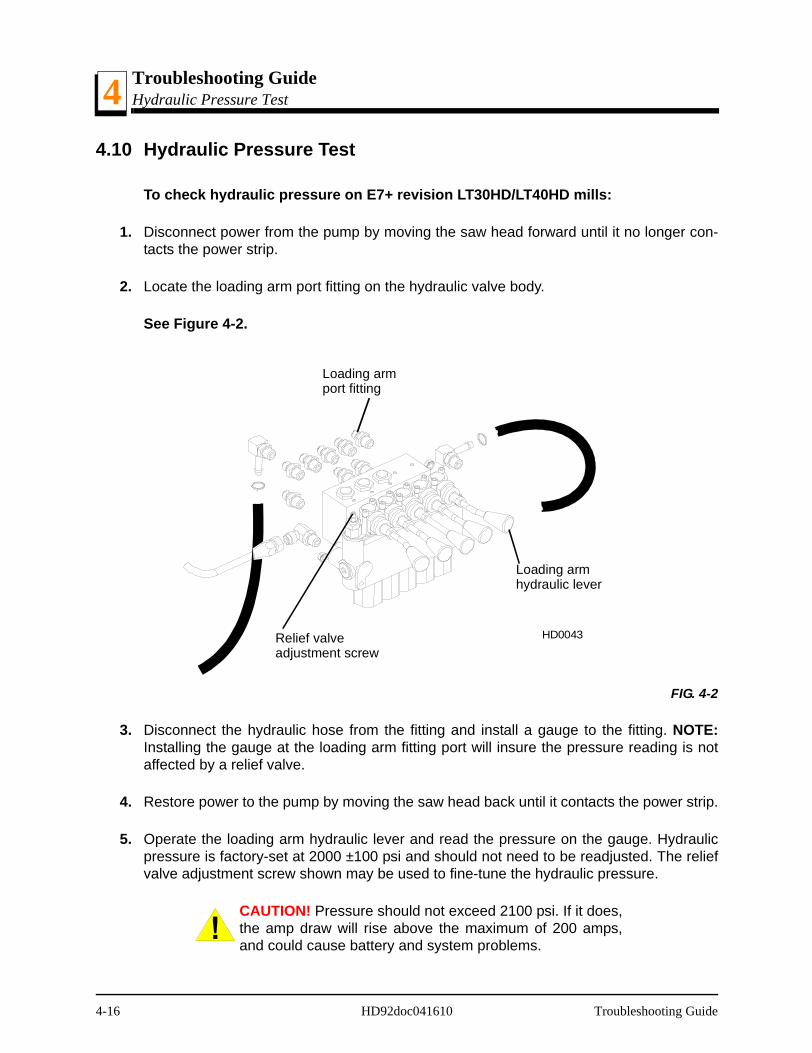
Troubleshooting GuideHydraulic Pressure Test4
4.10 Hydraulic Pressure Test
To check hydraulic pressure on E7+ revision LT30HD/LT40HD mills:
1. Disconnect power from the pump by moving the saw head forward until it no longer con-tacts the power strip.
2. Locate the loading arm port fitting on the hydraulic valve body.
See Figure 4-2.
3. Disconnect the hydraulic hose from the fitting and install a gauge to the fitting. NOTE:Installing the gauge at the loading arm fitting port will insure the pressure reading is notaffected by a relief valve.
4. Restore power to the pump by moving the saw head back until it contacts the power strip.
5. Operate the loading arm hydraulic lever and read the pressure on the gauge. Hydraulicpressure is factory-set at 2000 ±100 psi and should not need to be readjusted. The reliefvalve adjustment screw shown may be used to fine-tune the hydraulic pressure.
CAUTION! Pressure should not exceed 2100 psi. If it does,the amp draw will rise above the maximum of 200 amps,and could cause battery and system problems.
FIG. 4-2
Loading armport fitting
Loading armhydraulic lever
Relief valveadjustment screw
HD0043
4-16 HD92doc041610 Troubleshooting Guide
Troubleshooting GuideHydraulic Pressure Test 4
To check hydraulic pressure on C7 - E6 revision LT30HD/LT40HD mills:
1. Disconnect power from the pump by moving the saw head forward until it no longer con-tacts the power strip.
2. Locate the fitting on the front toe board cylinder. Disconnect the hydraulic hose from thefitting and install a gauge to the fitting. NOTE: Installing the gauge at the front toe boardfitting port will insure the pressure reading is not affected by a relief valve.
3. Restore power to the pump by moving the saw head back until it contacts the power strip.
4. Operate the toe board hydraulic lever and read the pressure on the gauge. Hydraulicpressure is factory-set at 2000 ±100 psi and should not need to be readjusted. Contactthe factory for service.
CAUTION! Pressure should not exceed 2100 psi. If it does,the amp draw will rise above the maximum of 200 amps,and could cause battery and system problems.
Troubleshooting Guide HD92doc041610 4-17

Sawmill AlignmentPre-Alignment Procedures 5
SECTION 5 SAWMILL ALIGNMENT
5.1 Pre-Alignment Procedures
The Wood-Mizer sawmill is factory aligned. Periodically check the sawmill alignment andadjust if necessary. This chapter explains how to align the entire sawmill. Care should betaken in performing these steps. Sawmill alignment determines the accuracy and square-ness of your cuts.
The sawmill alignment steps are:
1. Ready the sawmill for alignment
2. Adjust the main bed rails parallel to the blade
3. Adjust the blade guide arm parallel to the bed rails
4. Align blade guides to the blade
5. Adjust side supports square to the bed
6. Adjust pivot bed rails parallel to the blade
7. Final Adjustments
To insure accurate alignment, the sawmill frame must be level and a blade properlyinstalled.
Sawmill Alignment HD92doc041610 5-1
Sawmill AlignmentFrame Setup5
5.2 Frame Setup
Stationary sawmills should be setup on firm, level ground before proceeding with align-ment. Shim the feet so the weight of the sawmill is evenly supported.
Portable sawmills should also be setup on firm, level ground. Adjust the two middle out-riggers on the main frame tube down just enough to lift weight from the trailer tire.
Adjust the two outer outriggers down just so they touch the ground but do not bearweight.
5-2 HD92doc041610 Sawmill Alignment
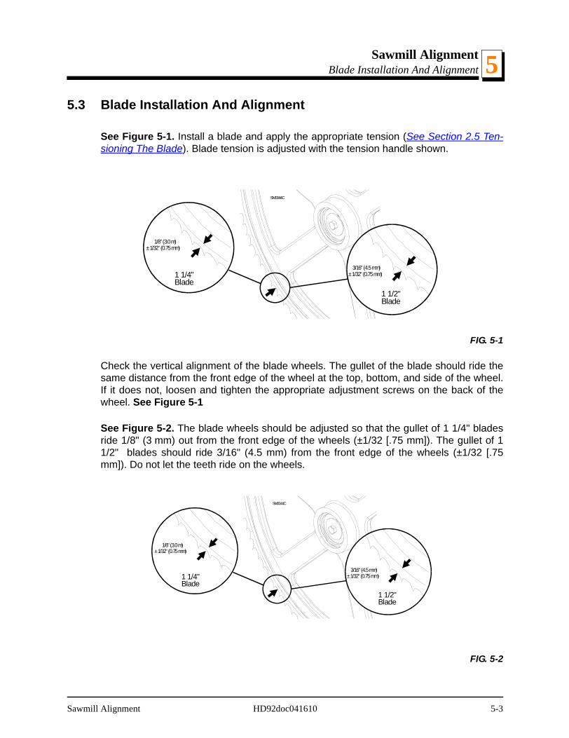
Sawmill AlignmentBlade Installation And Alignment 5
5.3 Blade Installation And Alignment
See Figure 5-1. Install a blade and apply the appropriate tension (See Section 2.5 Ten-sioning The Blade). Blade tension is adjusted with the tension handle shown.
Check the vertical alignment of the blade wheels. The gullet of the blade should ride thesame distance from the front edge of the wheel at the top, bottom, and side of the wheel.If it does not, loosen and tighten the appropriate adjustment screws on the back of thewheel. See Figure 5-1
See Figure 5-2. The blade wheels should be adjusted so that the gullet of 1 1/4" bladesride 1/8" (3 mm) out from the front edge of the wheels (±1/32 [.75 mm]). The gullet of 11/2" blades should ride 3/16" (4.5 mm) from the front edge of the wheels (±1/32 [.75mm]). Do not let the teeth ride on the wheels.
FIG. 5-1
FIG. 5-2
SM0044C
3/16" (4.5 mm)± 1/32" (0.75 mm)
1 1/2"Blade
1/8" (3.0 m)± 1/32" (0.75 mm)
1 1/4"Blade
SM0044C
3/16" (4.5 mm)± 1/32" (0.75 mm)
1 1/2"Blade
1/8" (3.0 m)± 1/32" (0.75 mm)
1 1/4"Blade
Sawmill Alignment HD92doc041610 5-3
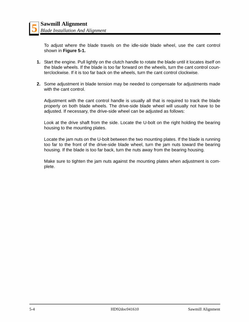
Sawmill AlignmentBlade Installation And Alignment5
To adjust where the blade travels on the idle-side blade wheel, use the cant controlshown in Figure 5-1.
1. Start the engine. Pull lightly on the clutch handle to rotate the blade until it locates itself onthe blade wheels. If the blade is too far forward on the wheels, turn the cant control coun-terclockwise. If it is too far back on the wheels, turn the cant control clockwise.
2. Some adjustment in blade tension may be needed to compensate for adjustments madewith the cant control.
Adjustment with the cant control handle is usually all that is required to track the bladeproperly on both blade wheels. The drive-side blade wheel will usually not have to beadjusted. If necessary, the drive-side wheel can be adjusted as follows:
Look at the drive shaft from the side. Locate the U-bolt on the right holding the bearinghousing to the mounting plates.
Locate the jam nuts on the U-bolt between the two mounting plates. If the blade is runningtoo far to the front of the drive-side blade wheel, turn the jam nuts toward the bearinghousing. If the blade is too far back, turn the nuts away from the bearing housing.
Make sure to tighten the jam nuts against the mounting plates when adjustment is com-plete.
5-4 HD92doc041610 Sawmill Alignment
Sawmill AlignmentSaw Head Slide Pad Adjustment 5
5.4 Saw Head Slide Pad Adjustment
There are eight nylon pads positioned between the saw head frame and vertical mast.The spacing of the pads is factory set and rarely needs adjusting. To check the pad spac-ing, perform the following steps.
NOTE: The pads on the engine side of the mast are referred to as the "inner" pads. Thepads on the control side of the mast are referred to as the "outer" pads.
NOTE: Shims are often used around the clamping bolts, between the C-frame supportbracket and the mast v-brace. The shims align the v-brace to the mast so that the entireface of each slide pad makes contact with the mast. Be sure to keep these shims in placewhen performing the following adjustment.
See Figure 5-3.
1. Raise the saw head to the top of the vertical mast. Check the top set of four pads.Theouter two pads should be touching the mast rails. There should be a small gap (just wideenough to slide a business card through) between one of the inner pads and the mast rail.
DANGER! Always secure the cutting head with a 5/16”chain with at least 1900 lbs. working load capacity beforeadjusting the mast pads. The cutting head may fall, causingsevere injury or death.
2. To adjust the spacing of the upper set of pads, lower the saw head until you can accessthe upper slide pad adjustment bolts.
3. Loosen the upper locking bolts and turn the adjusting bolt as necessary to provide thepad spacing described in Step 1.
4. Lower the saw head to the bottom of the vertical mast. Check the bottom set of four pads.
There should be a small gap between one of the outer pads and the mast rail. The gapshould be just wide enough to slide a business card through. The inner two pads shouldbe touching the mast rails.To adjust the spacing of the lower set of pads, raise the sawhead until you can access the lower slide pad adjustment bolts.
Sawmill Alignment HD92doc041610 5-5
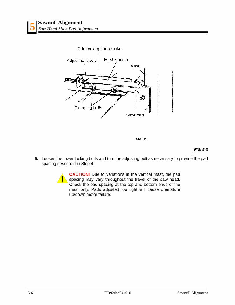
Sawmill AlignmentSaw Head Slide Pad Adjustment5
5. Loosen the lower locking bolts and turn the adjusting bolt as necessary to provide the padspacing described in Step 4.
CAUTION! Due to variations in the vertical mast, the padspacing may vary throughout the travel of the saw head.Check the pad spacing at the top and bottom ends of themast only. Pads adjusted too tight will cause prematureup/down motor failure.
FIG. 5-3
5-6 HD92doc041610 Sawmill Alignment
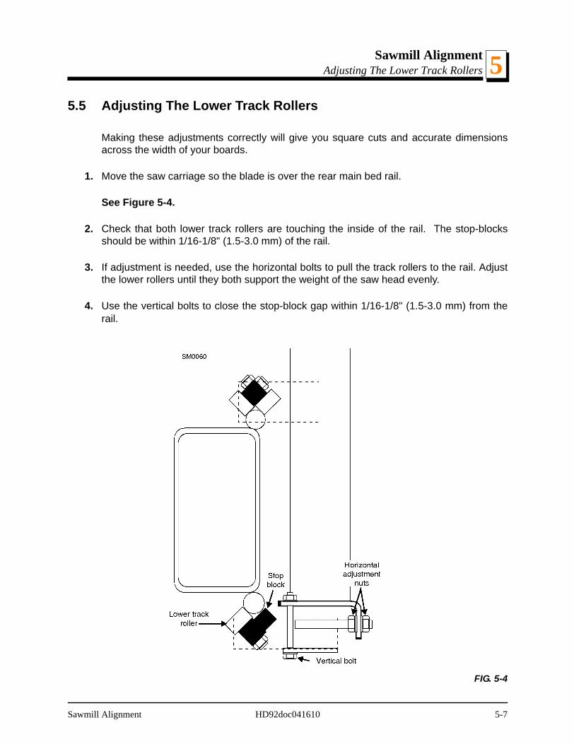
Sawmill AlignmentAdjusting The Lower Track Rollers 5
5.5 Adjusting The Lower Track Rollers
Making these adjustments correctly will give you square cuts and accurate dimensionsacross the width of your boards.
1. Move the saw carriage so the blade is over the rear main bed rail.
See Figure 5-4.
2. Check that both lower track rollers are touching the inside of the rail. The stop-blocksshould be within 1/16-1/8" (1.5-3.0 mm) of the rail.
3. If adjustment is needed, use the horizontal bolts to pull the track rollers to the rail. Adjustthe lower rollers until they both support the weight of the saw head evenly.
4. Use the vertical bolts to close the stop-block gap within 1/16-1/8" (1.5-3.0 mm) from therail.
FIG. 5-4
Sawmill Alignment HD92doc041610 5-7
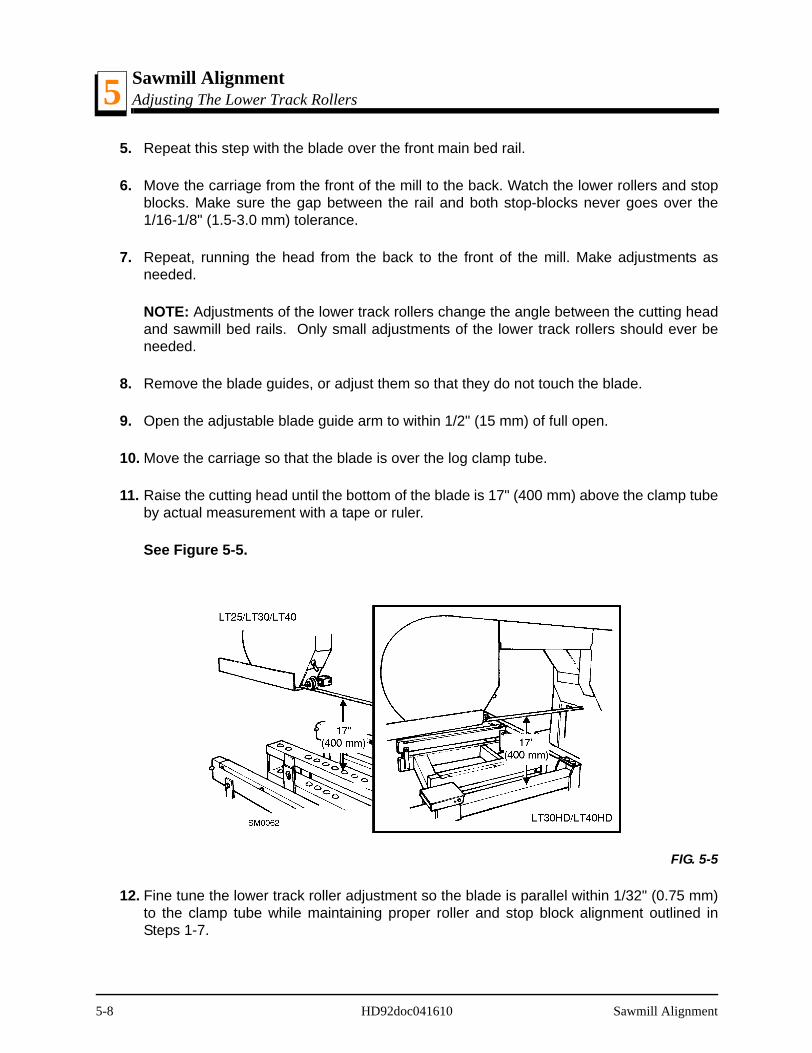
Sawmill AlignmentAdjusting The Lower Track Rollers5
5. Repeat this step with the blade over the front main bed rail.
6. Move the carriage from the front of the mill to the back. Watch the lower rollers and stopblocks. Make sure the gap between the rail and both stop-blocks never goes over the1/16-1/8" (1.5-3.0 mm) tolerance.
7. Repeat, running the head from the back to the front of the mill. Make adjustments asneeded.
NOTE: Adjustments of the lower track rollers change the angle between the cutting headand sawmill bed rails. Only small adjustments of the lower track rollers should ever beneeded.
8. Remove the blade guides, or adjust them so that they do not touch the blade.
9. Open the adjustable blade guide arm to within 1/2" (15 mm) of full open.
10. Move the carriage so that the blade is over the log clamp tube.
11. Raise the cutting head until the bottom of the blade is 17" (400 mm) above the clamp tubeby actual measurement with a tape or ruler.
See Figure 5-5.
12. Fine tune the lower track roller adjustment so the blade is parallel within 1/32" (0.75 mm)to the clamp tube while maintaining proper roller and stop block alignment outlined inSteps 1-7.
FIG. 5-5
5-8 HD92doc041610 Sawmill Alignment
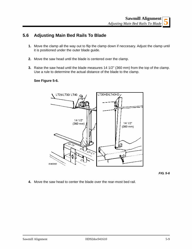
Sawmill AlignmentAdjusting Main Bed Rails To Blade 5
5.6 Adjusting Main Bed Rails To Blade
1. Move the clamp all the way out to flip the clamp down if neccesary. Adjust the clamp untilit is positioned under the outer blade guide.
2. Move the saw head until the blade is centered over the clamp.
3. Raise the saw head until the blade measures 14 1/2" (360 mm) from the top of the clamp.Use a rule to determine the actual distance of the blade to the clamp.
See Figure 5-6.
4. Move the saw head to center the blade over the rear-most bed rail.
FIG. 5-6
Sawmill Alignment HD92doc041610 5-9
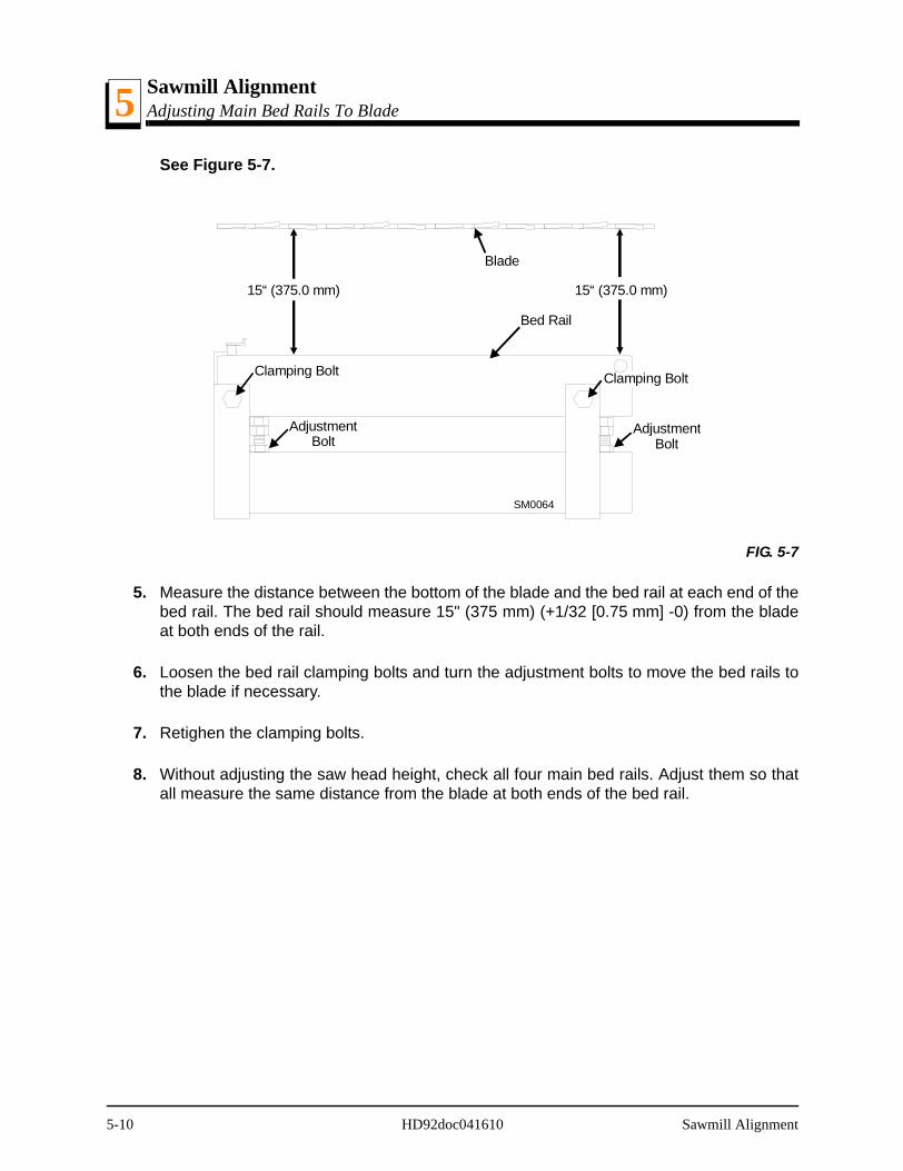
Sawmill AlignmentAdjusting Main Bed Rails To Blade5
See Figure 5-7.
5. Measure the distance between the bottom of the blade and the bed rail at each end of thebed rail. The bed rail should measure 15" (375 mm) (+1/32 [0.75 mm] -0) from the bladeat both ends of the rail.
6. Loosen the bed rail clamping bolts and turn the adjustment bolts to move the bed rails tothe blade if necessary.
7. Retighen the clamping bolts.
8. Without adjusting the saw head height, check all four main bed rails. Adjust them so thatall measure the same distance from the blade at both ends of the bed rail.
FIG. 5-7
15“ (375.0 mm) 15“ (375.0 mm)
Blade
Bed Rail
Clamping BoltClamping Bolt
AdjustmentBolt
AdjustmentBolt
SM0064
5-10 HD92doc041610 Sawmill Alignment
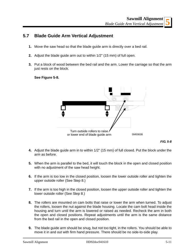
Sawmill AlignmentBlade Guide Arm Vertical Adjustment 5
5.7 Blade Guide Arm Vertical Adjustment
1. Move the saw head so that the blade guide arm is directly over a bed rail.
2. Adjust the blade guide arm out to within 1/2" (15 mm) of full open.
3. Put a block of wood between the bed rail and the arm. Lower the carriage so that the armjust rests on the block.
See Figure 5-8.
4. Adjust the blade guide arm in to within 1/2" (15 mm) of full closed. Put the block under thearm as before.
5. When the arm is parallel to the bed, it will touch the block in the open and closed positionwith no adjustment of the saw head height.
6. If the arm is too low in the closed position, loosen the lower outside roller and tighten theupper outside roller (See Step 8.)
7. If the arm is too high in the closed position, loosen the upper outside roller and tighten thelower outside roller (See Step 8.)
8. The rollers are mounted on cam bolts that raise or lower the arm when turned. To adjustthe rollers, loosen the nut against the blade housing. Locate the cam bolt head inside thehousing and turn until the arm is lowered or raised as needed. Recheck the arm in boththe open and closed positions. Repeat adjustments until the arm is the same distancefrom the bed rail in the open and closed position.
9. The blade guide arm should be snug, but not too tight, in the rollers. You should be able tomove it in and out with firm hand pressure. There should be no side-to-side play.
FIG. 5-8
Turn outside rollers to raiseor lower end of blade guide arm SM0065B
Sawmill Alignment HD92doc041610 5-11
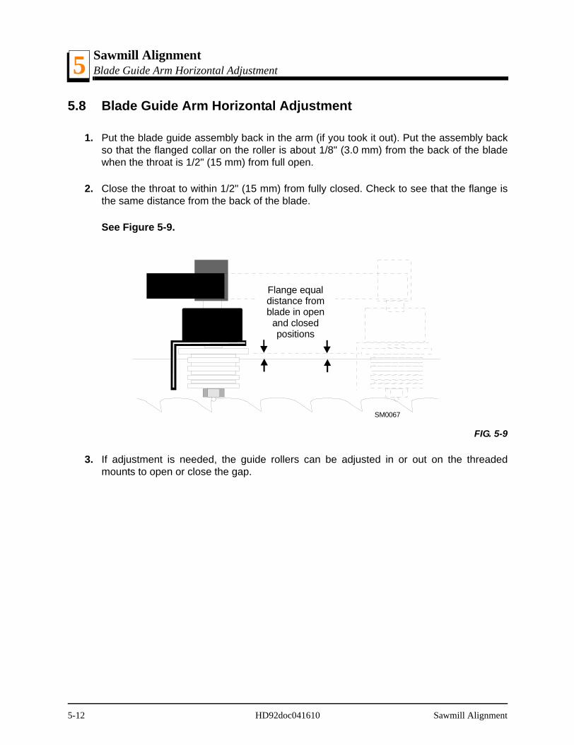
Sawmill AlignmentBlade Guide Arm Horizontal Adjustment5
5.8 Blade Guide Arm Horizontal Adjustment
1. Put the blade guide assembly back in the arm (if you took it out). Put the assembly backso that the flanged collar on the roller is about 1/8" (3.0 mm) from the back of the bladewhen the throat is 1/2" (15 mm) from full open.
2. Close the throat to within 1/2" (15 mm) from fully closed. Check to see that the flange isthe same distance from the back of the blade.
See Figure 5-9.
3. If adjustment is needed, the guide rollers can be adjusted in or out on the threadedmounts to open or close the gap.
FIG. 5-9
Flange equaldistance fromblade in open
and closedpositions
SM0067
5-12 HD92doc041610 Sawmill Alignment
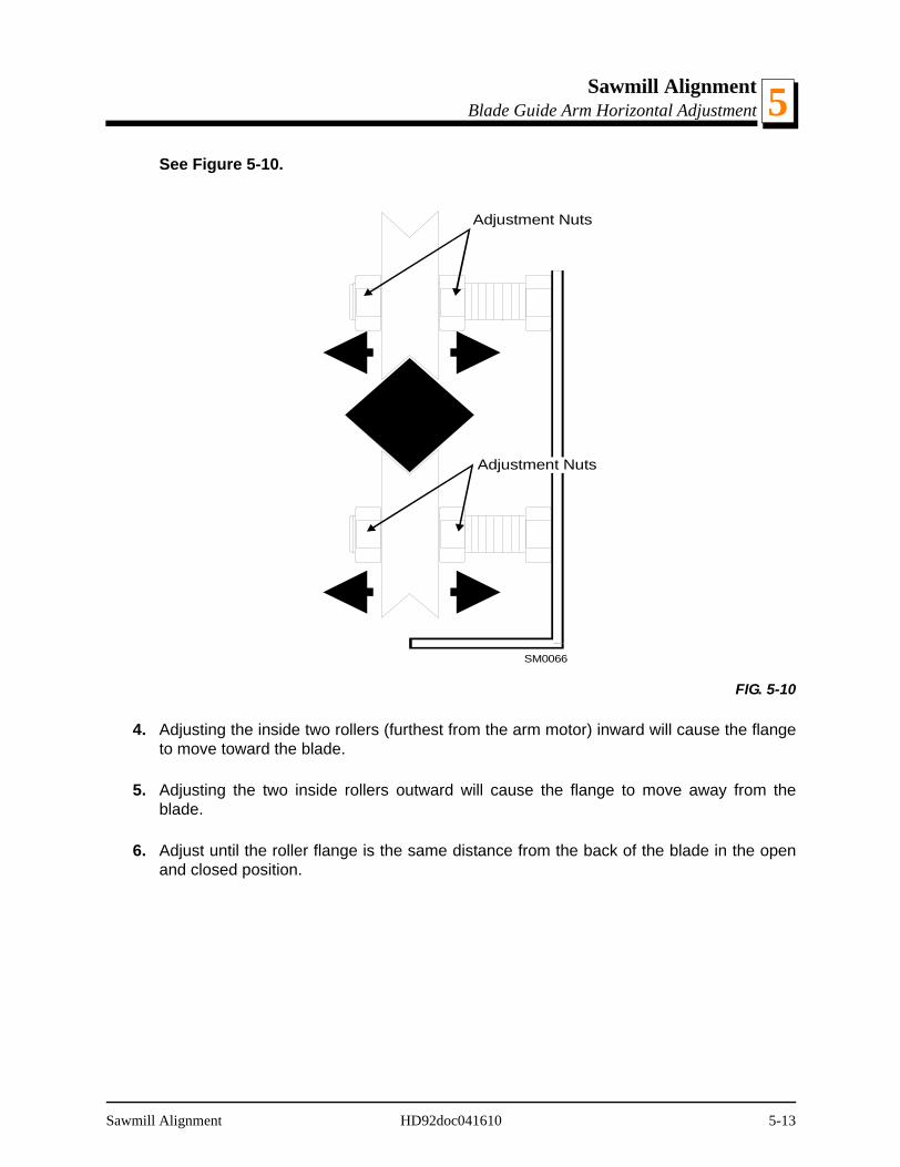
Sawmill AlignmentBlade Guide Arm Horizontal Adjustment 5
See Figure 5-10.
4. Adjusting the inside two rollers (furthest from the arm motor) inward will cause the flangeto move toward the blade.
5. Adjusting the two inside rollers outward will cause the flange to move away from theblade.
6. Adjust until the roller flange is the same distance from the back of the blade in the openand closed position.
FIG. 5-10
Adjustment Nuts
Adjustment Nuts
SM0066
Sawmill Alignment HD92doc041610 5-13

Sawmill AlignmentAligning The Blade Guides5
5.9 Aligning The Blade Guides
Each Wood-Mizer sawmill has two blade guide assemblies that help the blade maintain astraight cut. The two blade guide assemblies are positioned on the saw head to guide theblade on each side of the material being cut.
One blade guide assembly is mounted in a stationary position on the drive side of the sawhead. This assembly is referred to as the "inner" blade guide assembly.
The other blade guide assembly is mounted on the idle side of the saw head. It is referredto as the "outer" assembly and is adjustable for various widths of materials to be pro-cessed.
Blade guide alignment includes four steps:
Blade Deflection
Blade Guide Vertical Tilt
Blade Guide Flange Spacing
Blade Guide Horizontal Tilt
Perform the blade guide alignment after you have aligned the blade on the wheels andadjusted the blade and blade guide arm parallel to the bed rails. After blade guide align-ment, check the scale indicator to make sure it is adjusted properly (See Section 5.20Blade Height Scale Adjustment).
5-14 HD92doc041610 Sawmill Alignment
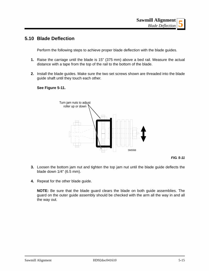
Sawmill AlignmentBlade Deflection 5
5.10 Blade Deflection
Perform the following steps to achieve proper blade deflection with the blade guides.
1. Raise the carriage until the blade is 15" (375 mm) above a bed rail. Measure the actualdistance with a tape from the top of the rail to the bottom of the blade.
2. Install the blade guides. Make sure the two set screws shown are threaded into the bladeguide shaft until they touch each other.
See Figure 5-11.
3. Loosen the bottom jam nut and tighten the top jam nut until the blade guide deflects theblade down 1/4" (6.5 mm).
4. Repeat for the other blade guide.
NOTE: Be sure that the blade guard clears the blade on both guide assemblies. Theguard on the outer guide assembly should be checked with the arm all the way in and allthe way out.
FIG. 5-11
Turn jam nuts to adjustroller up or down
SM0068
Sawmill Alignment HD92doc041610 5-15
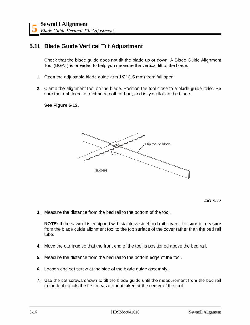
Sawmill AlignmentBlade Guide Vertical Tilt Adjustment5
5.11 Blade Guide Vertical Tilt Adjustment
Check that the blade guide does not tilt the blade up or down. A Blade Guide AlignmentTool (BGAT) is provided to help you measure the vertical tilt of the blade.
1. Open the adjustable blade guide arm 1/2" (15 mm) from full open.
2. Clamp the alignment tool on the blade. Position the tool close to a blade guide roller. Besure the tool does not rest on a tooth or burr, and is lying flat on the blade.
See Figure 5-12.
3. Measure the distance from the bed rail to the bottom of the tool.
NOTE: If the sawmill is equipped with stainless steel bed rail covers, be sure to measurefrom the blade guide alignment tool to the top surface of the cover rather than the bed railtube.
4. Move the carriage so that the front end of the tool is positioned above the bed rail.
5. Measure the distance from the bed rail to the bottom edge of the tool.
6. Loosen one set screw at the side of the blade guide assembly.
7. Use the set screws shown to tilt the blade guide until the measurement from the bed railto the tool equals the first measurement taken at the center of the tool.
FIG. 5-12
Clip tool to blade
SM0069B
5-16 HD92doc041610 Sawmill Alignment
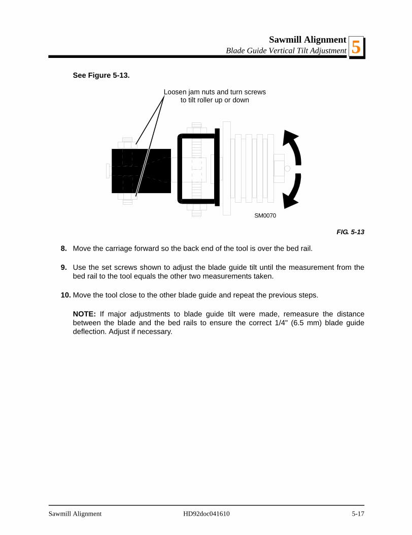
Sawmill AlignmentBlade Guide Vertical Tilt Adjustment 5
See Figure 5-13.
8. Move the carriage forward so the back end of the tool is over the bed rail.
9. Use the set screws shown to adjust the blade guide tilt until the measurement from thebed rail to the tool equals the other two measurements taken.
10. Move the tool close to the other blade guide and repeat the previous steps.
NOTE: If major adjustments to blade guide tilt were made, remeasure the distancebetween the blade and the bed rails to ensure the correct 1/4" (6.5 mm) blade guidedeflection. Adjust if necessary.
FIG. 5-13
SM0070
Loosen jam nuts and turn screwsto tilt roller up or down
Sawmill Alignment HD92doc041610 5-17
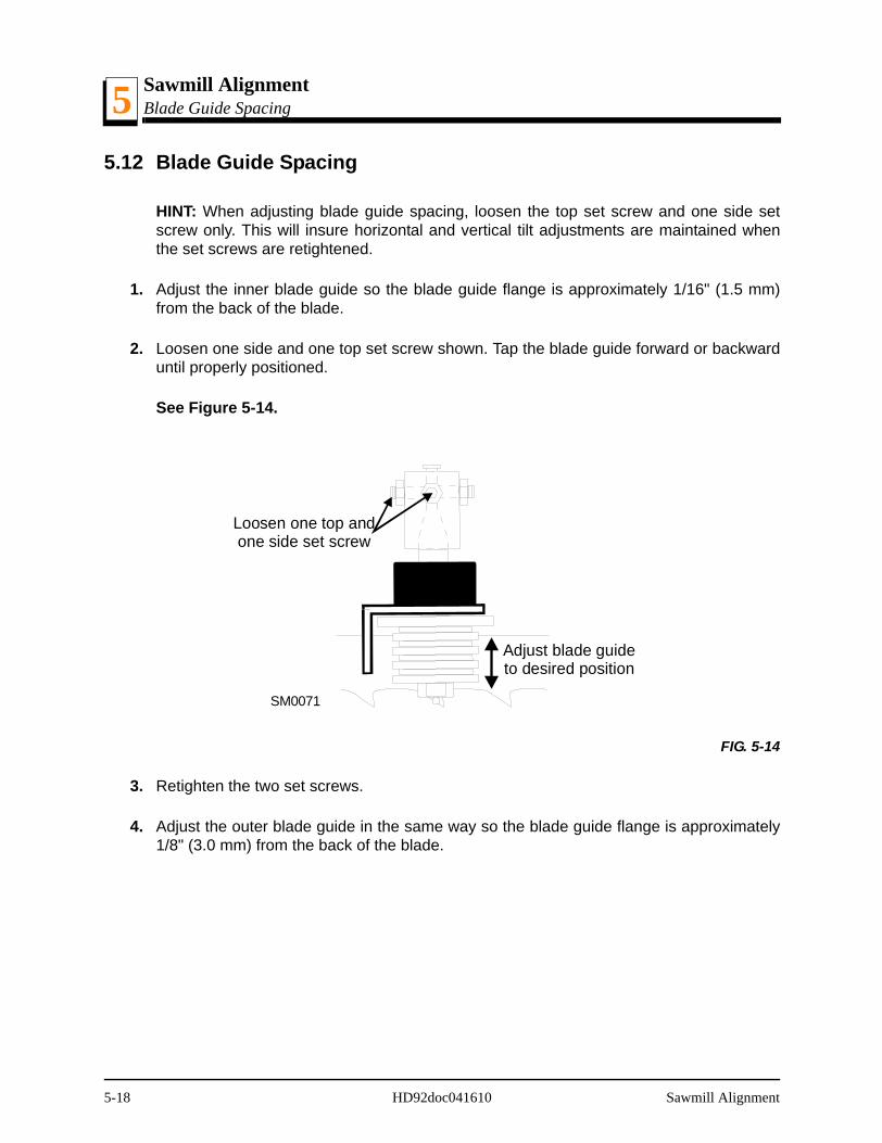
Sawmill AlignmentBlade Guide Spacing5
5.12 Blade Guide Spacing
HINT: When adjusting blade guide spacing, loosen the top set screw and one side setscrew only. This will insure horizontal and vertical tilt adjustments are maintained whenthe set screws are retightened.
1. Adjust the inner blade guide so the blade guide flange is approximately 1/16" (1.5 mm)from the back of the blade.
2. Loosen one side and one top set screw shown. Tap the blade guide forward or backwarduntil properly positioned.
See Figure 5-14.
3. Retighten the two set screws.
4. Adjust the outer blade guide in the same way so the blade guide flange is approximately1/8" (3.0 mm) from the back of the blade.
FIG. 5-14
Loosen one top andone side set screw
Adjust blade guideto desired position
SM0071
5-18 HD92doc041610 Sawmill Alignment
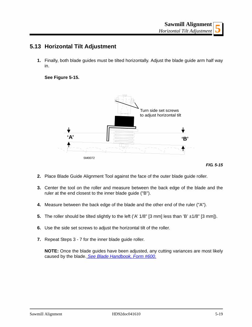
Sawmill AlignmentHorizontal Tilt Adjustment 5
5.13 Horizontal Tilt Adjustment
1. Finally, both blade guides must be tilted horizontally. Adjust the blade guide arm half wayin.
See Figure 5-15.
2. Place Blade Guide Alignment Tool against the face of the outer blade guide roller.
3. Center the tool on the roller and measure between the back edge of the blade and theruler at the end closest to the inner blade guide ("B").
4. Measure between the back edge of the blade and the other end of the ruler ("A").
5. The roller should be tilted slightly to the left (’A’ 1/8" [3 mm] less than ’B’ ±1/8" [3 mm]).
6. Use the side set screws to adjust the horizontal tilt of the roller.
7. Repeat Steps 3 - 7 for the inner blade guide roller.
NOTE: Once the blade guides have been adjusted, any cutting variances are most likelycaused by the blade. See Blade Handbook, Form #600.
FIG. 5-15
Turn side set screwsto adjust horizontal tilt
SM0072
‘A’ ‘B’
Sawmill Alignment HD92doc041610 5-19
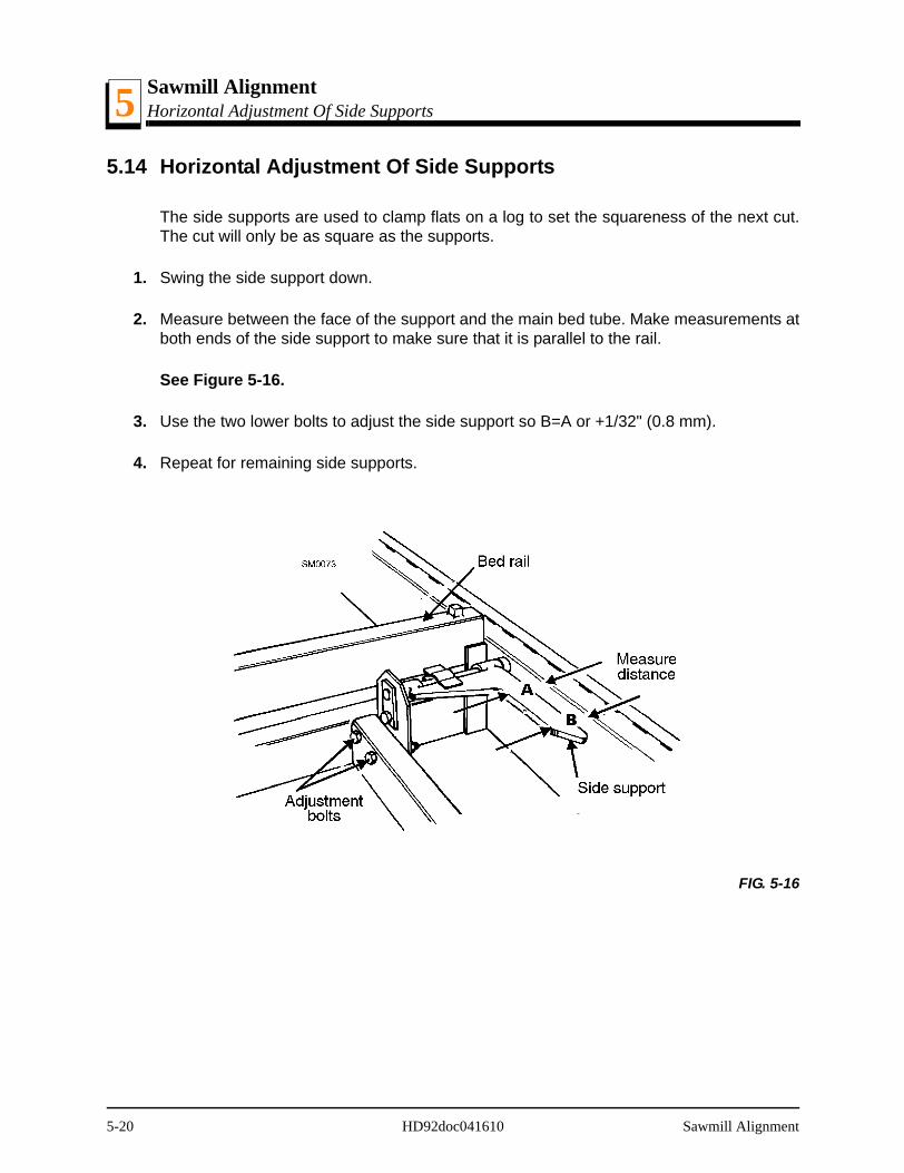
Sawmill AlignmentHorizontal Adjustment Of Side Supports5
5.14 Horizontal Adjustment Of Side Supports
The side supports are used to clamp flats on a log to set the squareness of the next cut.The cut will only be as square as the supports.
1. Swing the side support down.
2. Measure between the face of the support and the main bed tube. Make measurements atboth ends of the side support to make sure that it is parallel to the rail.
See Figure 5-16.
3. Use the two lower bolts to adjust the side support so B=A or +1/32" (0.8 mm).
4. Repeat for remaining side supports.
FIG. 5-16
5-20 HD92doc041610 Sawmill Alignment
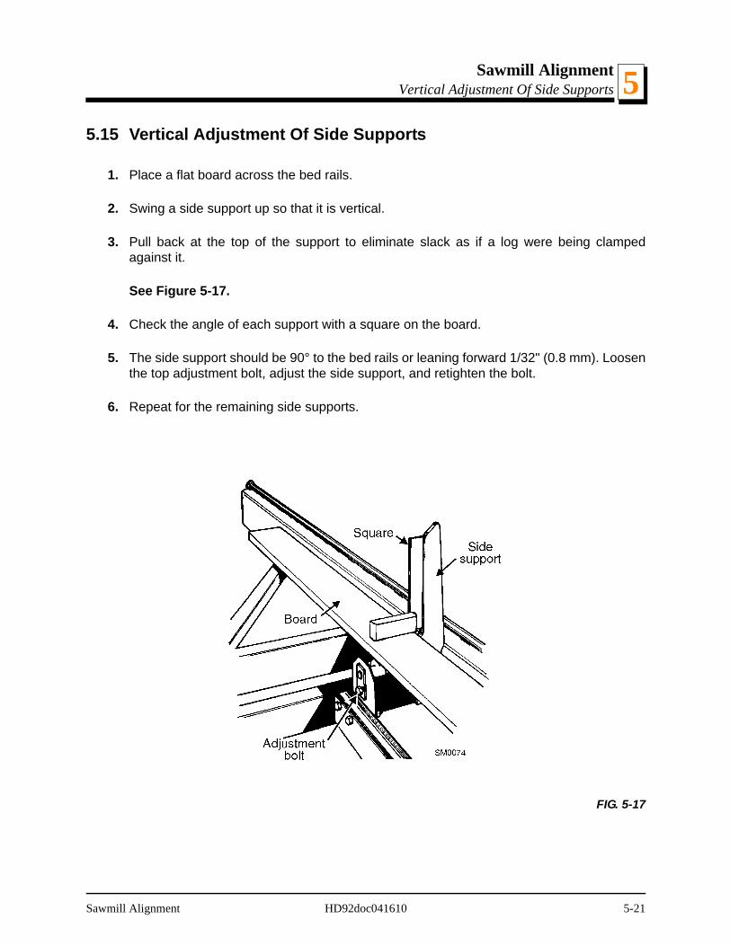
Sawmill AlignmentVertical Adjustment Of Side Supports 5
5.15 Vertical Adjustment Of Side Supports
1. Place a flat board across the bed rails.
2. Swing a side support up so that it is vertical.
3. Pull back at the top of the support to eliminate slack as if a log were being clampedagainst it.
See Figure 5-17.
4. Check the angle of each support with a square on the board.
5. The side support should be 90° to the bed rails or leaning forward 1/32" (0.8 mm). Loosenthe top adjustment bolt, adjust the side support, and retighten the bolt.
6. Repeat for the remaining side supports.
FIG. 5-17
Sawmill Alignment HD92doc041610 5-21
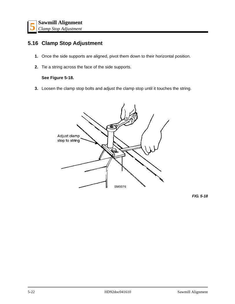
Sawmill AlignmentClamp Stop Adjustment5
5.16 Clamp Stop Adjustment
1. Once the side supports are aligned, pivot them down to their horizontal position.
2. Tie a string across the face of the side supports.
See Figure 5-18.
3. Loosen the clamp stop bolts and adjust the clamp stop until it touches the string.
FIG. 5-18
5-22 HD92doc041610 Sawmill Alignment
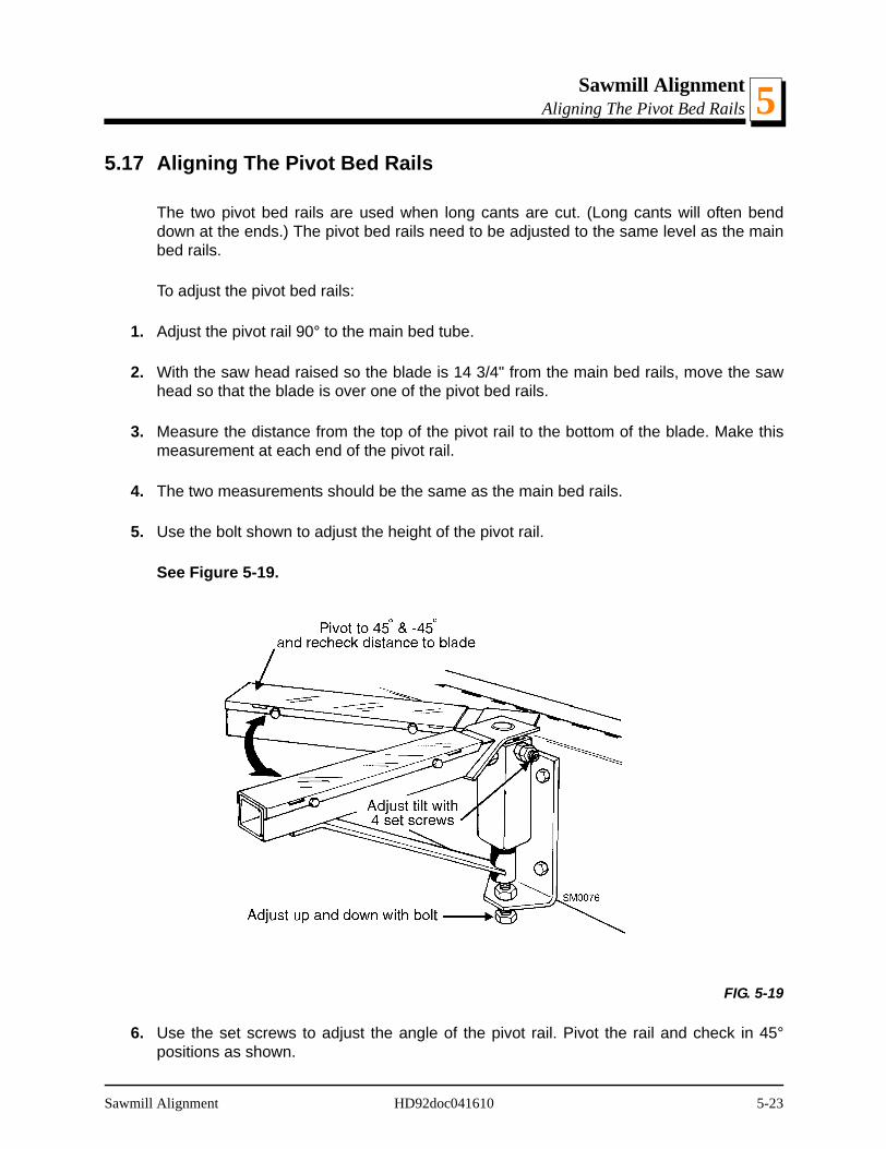
Sawmill AlignmentAligning The Pivot Bed Rails 5
5.17 Aligning The Pivot Bed Rails
The two pivot bed rails are used when long cants are cut. (Long cants will often benddown at the ends.) The pivot bed rails need to be adjusted to the same level as the mainbed rails.
To adjust the pivot bed rails:
1. Adjust the pivot rail 90° to the main bed tube.
2. With the saw head raised so the blade is 14 3/4" from the main bed rails, move the sawhead so that the blade is over one of the pivot bed rails.
3. Measure the distance from the top of the pivot rail to the bottom of the blade. Make thismeasurement at each end of the pivot rail.
4. The two measurements should be the same as the main bed rails.
5. Use the bolt shown to adjust the height of the pivot rail.
See Figure 5-19.
6. Use the set screws to adjust the angle of the pivot rail. Pivot the rail and check in 45°positions as shown.
FIG. 5-19
Sawmill Alignment HD92doc041610 5-23

Sawmill AlignmentAligning The Pivot Bed Rails5
7. Adjust as needed until the pivot rail measures the same distance (±1/32) from the blade inthe 45°, 90°, and -45° positions.
CAUTION! Do not roll logs or large cants onto pivot bedrails.
IMPORTANT! Logs and large cants will damage the pivotbed rails or cause misalignment!
5-24 HD92doc041610 Sawmill Alignment

Sawmill AlignmentSight Gauge Adjustment 5
5.18 Sight Gauge Adjustment
After adjustments to the bed rails and blade guides are complete, adjust the sight gaugeso that it accurately shows the position of the blade over the bed rails.
1. Move the saw head so the sight gauge is positioned over a bed rail.
2. Measure from the bed rail to the top of the sight gauge spring.
3. Loosen the nuts securing the sight gauge and adjust until the top of the spring is the samedistance from the bed rail as the blade.
4. Retighten the sight gauge nuts.
5. Bend the sight gauge bracket so the spring is parallel to the bed rails.
Sawmill Alignment HD92doc041610 5-25
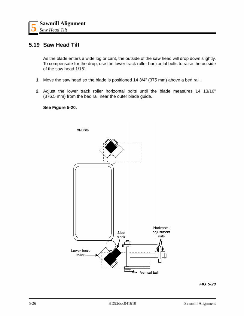
Sawmill AlignmentSaw Head Tilt5
5.19 Saw Head Tilt
As the blade enters a wide log or cant, the outside of the saw head will drop down slightly.To compensate for the drop, use the lower track roller horizontal bolts to raise the outsideof the saw head 1/16".
1. Move the saw head so the blade is positioned 14 3/4" (375 mm) above a bed rail.
2. Adjust the lower track roller horizontal bolts until the blade measures 14 13/16"(376.5 mm) from the bed rail near the outer blade guide.
See Figure 5-20.
FIG. 5-20
5-26 HD92doc041610 Sawmill Alignment
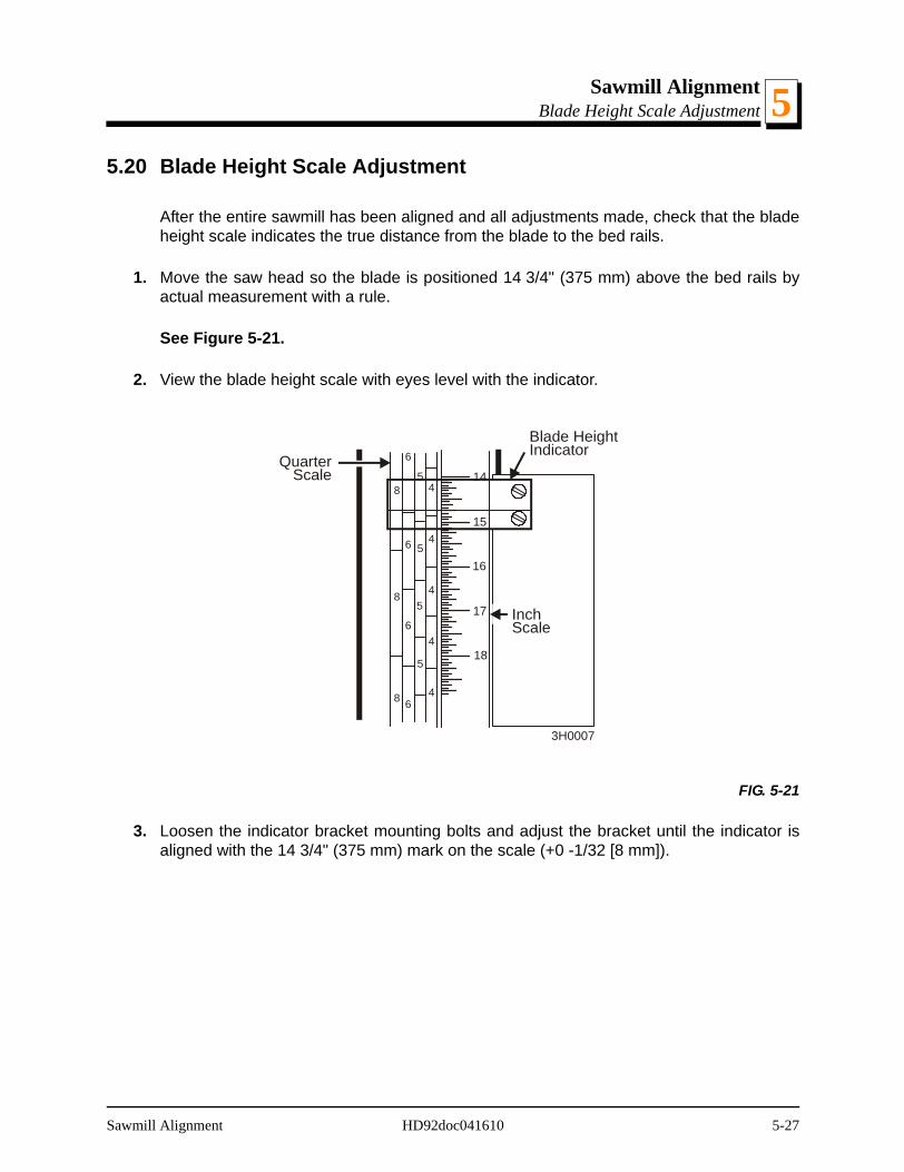
Sawmill AlignmentBlade Height Scale Adjustment 5
5.20 Blade Height Scale Adjustment
After the entire sawmill has been aligned and all adjustments made, check that the bladeheight scale indicates the true distance from the blade to the bed rails.
1. Move the saw head so the blade is positioned 14 3/4" (375 mm) above the bed rails byactual measurement with a rule.
See Figure 5-21.
2. View the blade height scale with eyes level with the indicator.
3. Loosen the indicator bracket mounting bolts and adjust the bracket until the indicator isaligned with the 14 3/4" (375 mm) mark on the scale (+0 -1/32 [8 mm]).
FIG. 5-21
15
16
17
18
144
4
4
4
4
5
5
5
5
6
6
6
6
8
8
8
QuarterScale
Blade HeightIndicator
InchScale
3H0007
Sawmill Alignment HD92doc041610 5-27


INDEX
A
alignmentblade guide 5-14blade installation 5-3frame setup 5-2lower track rollers 5-7main bed rails 5-9pivot bed rails 5-23sawmill 5-1slide pad adjustment 5-5
B
batterytroubleshooting problems 4-3
beltup/down tension 3-22
bladebreakage, troubleshooting 4-1deflection 5-15installation 2-7tensioning 2-8tracking 2-9
blade guidehorizontal tilt 5-19maintenance 3-2spacing 5-18vertical tilt 5-16
blade guide armoperation 2-21
brake straptension 3-12
C
chainfeed tension 3-20maintenance 3-9up/down tension 3-19
clamping logs 2-17clamp extension accessory 2-19
clutch/brake leveroperation 2-22
H
hydrauliccomponents 1-17control operation 2-12fluid level 3-14hoses 1-19schematic 1-15, 1-16troubleshooting problems 4-9
L
leveling logs 2-18
loading logs 2-16
O
operationedging 2-26sawing 2-25
Index HD92doc041610 i

INDEX
P
power feedmechanical troubleshooting test 4-15operation 2-24preliminary troubleshooting test 4-14speed adjustment 2-23troubleshooting problems 4-5
R
retrofitsblade guide set screws 3-2fuse block 3-22
S
safetylockout procedure 1-7
saw headtilt 5-26
scaleblade height adjustment 5-27blade height operation 2-28inch height 2-29quarter inch 2-30
setupportable sawmill 2-2sawmill for operation 2-6stationary sawmill 2-1
side supportshorizontal adjustment 5-20vertical adjustment 5-21
sight gaugeadjustment 5-25
switchpower feed & up/down maintenance 3-8
T
tensionermaintenance 3-10
trackmaintenance 3-5
troubleshooting 4-1electrical problems 4-3hydraulic problems 4-9power feed problems 4-5sawing problems 4-1
turning logs 2-17
U
up/downoperation 2-20sight gauge operation 2-27troubleshooting problems 4-3
W
water lubeoperation 2-31
ii HD92doc041610 Index