operator’s manual for: resilience slashers - · pdf fileoperator’s manual for:...
TRANSCRIPT

Page 1 of 22
Operator’s Manual for:
Resilience Slashers
SD1500 (5ft) Standard Duty Slasher c/w 45hp gearbox
HD1500 (5ft) Heavy Duty Slasher c/w 75hp Gearbox
HD1800 (6ft)
Page 2 of 22
Contents: Page INTRODUCTION: 3
SAFETY 3-4
DESCRIPTION 5
TECHNICAL SPECIFICATIONS 5
PREPARATION FOR USE 6-8 SETTING THE PTO DRIVE SHAFT LENGTH CUTTING HEIGHT ADJUSTMENT
OPERATING INSTRUCTIONS 9-11 GENERAL SAFETY LIMITATIONS OPERATION TRANSPORTING
MAINTENANCE 11-13 TORQUE CHART BEFORE EACH USE LUBRICATION SLIP CLUTCH OPERATIONAL CHECK SLIP CLUTCH ADJUSTMENT GEARBOX MAINTENANCE
TROUBLESHOOTING 14
ASSEMBLY 14-20 SAFETY PRECAUTIONS PROCEDURE
COMMISSIONING CHECKLIST 21
RUN UP TEST 21

Page 3 of 22
INTRODUCTION
Congratulations on your purchase of an Ag-bits slasher. These machines have been carefully designed to be functional, robust & simple to use & maintain. This manual is provided to give you the necessary operating & maintenance instructions for keeping your rotary slasher in good operating condition. Please read this manual thoroughly, in conjunction with the complimentary “Ag-bits MACHINE SAFETY MANUAL” which also contains Machine Commissioning, Warranty Registration & Policy. The warranty on your machine will not be valid until the “Commissioning Checklist & Warranty Registration” form has been filled out & returned to Ag-bits (address on back cover). You must understand what each control is for & how to use it. Observe all safety advice provided by decals on the machine & throughout the manuals for safe operation of implement. If any assistance or additional information is needed, contact your dealer or Ag-bits (office open 8am – 5pm Mon- Fri).
SAFETY
General
Read the manual entirely. When you see this symbol, the
subsequent instructions & warnings are serious –follow without
exception. Your life & lives of other depend on it! This manual
contains valuable information about your new slasher. It has been
carefully prepared to give you helpful suggestions for operating, adjusting, &
servicing. Keep this manual in a convenient place for quick & easy reference.
Study it carefully, only by proper care & operation can you expect to receive
the service & long life designed & built into this unit. It is the owner’s &/or
operator’s responsibility to….
Read & understand the information contained in this manual.
Operate, lubricate, assemble & maintain the equipment in accordance with all instructions & safety procedures in this manual.
Inspect the equipment & replace or repair any parts that are damaged or worn which could cause damage, wear to other parts, or cause a safety hazard.

Page 4 of 22
The warnings, cautions & instructions discussed in this instruction manual cannot cover all possible conditions & situations that may occur. You must seek out & minimize potential risk factors.
Never permit any riders on equipment.
Stop engine, disconnect the power source, & wait for all machine movement to stop before servicing, adjusting, cleaning or unclogging the equipment.
Make sure everyone is clear of machinery before starting the engine,
engaging power, or operating the machine.
Only use a tractor that has a certified ROPS.
Securely fasten your seat belt.
Where possible, avoid operating the tractor near ditches, embankments, & holes.
Reduce speed when turning, crossing slopes, & on rough, slick, or muddy surfaces.
Stay off slopes too steep for safe operation.
Watch where you are going, especially at row ends, on roads, & around trees.
Operate the tractor smoothly - no sudden turns, starts, or stops.
Hitch only to the drawbar or hitch points recommended by tractor manufacturers.
When tractor is stopped, set brakes securely & use park lock if available.
Further safety advice is provided in the Operating Instructions section on pages 9-11

Page 5 of 22
DESCRIPTION
The SD1500, HD1500 & HD1800 slashers are designed for medium to heavy duty applications such as cutting thick grass, heavy brush, saplings, scrub & small trees. These slashers use a single spindle with two free-swinging blades, mounted on a spring steel laminated blade beam. Free-swinging blades reduce the shock of impact when a stationary object is hit & the spring steel beam has additional shock absorption properties, which helps protect the gearbox from damage. Additional protection is provided by a slip clutch on the gearbox input shaft. All models are attached to the tractor using Cat.1 3 point hitches, Cat.2 hitches can be accommodated using proprietary bushes, available from most tractor dealers. Standard safety equipment includes PTO shaft covers, PTO clutch cover & front & rear discharge chain guards (for reducing ejected projectiles). NOTE All references made to right, left, front, rear, top or bottom are as viewed facing the direction of forward travel with implement properly attached to tractor.
TECHNICAL SPECIFICATIONS
Model SD1500 HD1500 HD1800
SLASHER Diameter
1480mm* 1480mm* 1780mm*
Body length 1950mm 1950mm 2260mm
Body width (c/w side skids) 1710mm 1710mm 2010mm
Gearbox Capacity 45Hp 75Hp 75Hp
Min. HP (recommended) 30Hp 40Hp 50Hp
Cutting Height 30 -180mm 30 -180mm 30 -180mm
Drive shaft Series 4 Series 6 Series 6
Deck Thickness 5mm 5mm 5mm
Working Weight 316 Kgs 378 Kgs 447 Kgs
Body length & weight includes front & rear chains.
SPECIFICATIONS SUBJECT TO CHANGE WITHOUT NOTICE
* cutting width can vary slightly according to blade type used
Page 6 of 22
PREPARATION FOR USE
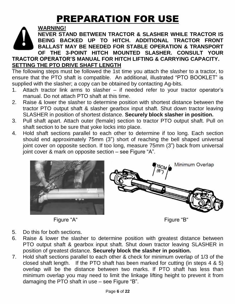
WARNING! NEVER STAND BETWEEN TRACTOR & SLASHER WHILE TRACTOR IS BEING BACKED UP TO HITCH. ADDITIONAL TRACTOR FRONT BALLAST MAY BE NEEDED FOR STABLE OPERATION & TRANSPORT OF THE 3-POINT HITCH MOUNTED SLASHER. CONSULT YOUR
TRACTOR OPERATOR’S MANUAL FOR HITCH LIFTING & CARRYING CAPACITY. SETTING THE PTO DRIVE SHAFT LENGTH The following steps must be followed the 1st time you attach the slasher to a tractor, to ensure that the PTO shaft is compatible. An additional, illustrated “PTO BOOKLET” is supplied with the slasher; a copy can be obtained by contacting Ag-bits. 1. Attach tractor link arms to slasher – if needed refer to your tractor operator’s
manual. Do not attach PTO shaft at this time. 2. Raise & lower the slasher to determine position with shortest distance between the
tractor PTO output shaft & slasher gearbox input shaft. Shut down tractor leaving SLASHER in position of shortest distance. Securely block slasher in position.
3. Pull shaft apart. Attach outer (female) section to tractor PTO output shaft. Pull on shaft section to be sure that yoke locks into place.
4. Hold shaft sections parallel to each other to determine if too long. Each section should end approximately 75mm (3”) short of reaching the bell shaped universal joint cover on opposite section. If too long, measure 75mm (3”) back from universal joint cover & mark on opposite section – see Figure “A”.
Figure “A“ Figure “B“ 5. Do this for both sections. 6. Raise & lower the slasher to determine position with greatest distance between
PTO output shaft & gearbox input shaft. Shut down tractor leaving SLASHER in position of greatest distance. Securely block the slasher in position.
7. Hold shaft sections parallel to each other & check for minimum overlap of 1/3 of the closed shaft length. If the PTO shaft has been marked for cutting (in steps 4 & 5) overlap will be the distance between two marks. If PTO shaft has less than minimum overlap you may need to limit the linkage lifting height to prevent it from damaging the PTO shaft in use – see Figure “B”.
Page 7 of 22
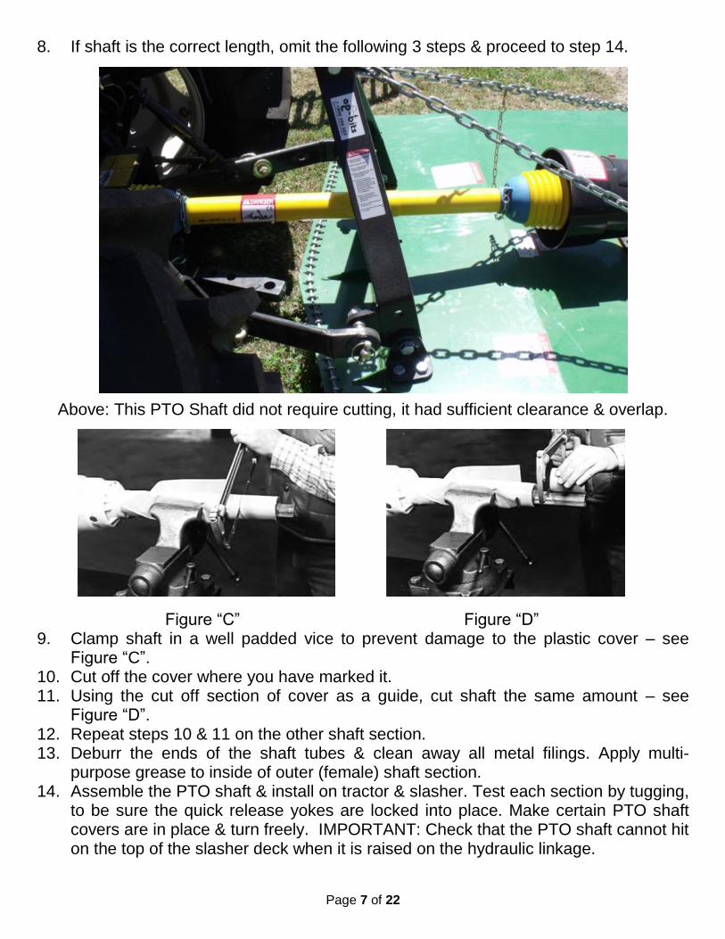
8. If shaft is the correct length, omit the following 3 steps & proceed to step 14.
Above: This PTO Shaft did not require cutting, it had sufficient clearance & overlap.
Figure “C” Figure “D” 9. Clamp shaft in a well padded vice to prevent damage to the plastic cover – see
Figure “C”. 10. Cut off the cover where you have marked it. 11. Using the cut off section of cover as a guide, cut shaft the same amount – see
Figure “D”. 12. Repeat steps 10 & 11 on the other shaft section. 13. Deburr the ends of the shaft tubes & clean away all metal filings. Apply multi-
purpose grease to inside of outer (female) shaft section. 14. Assemble the PTO shaft & install on tractor & slasher. Test each section by tugging,
to be sure the quick release yokes are locked into place. Make certain PTO shaft covers are in place & turn freely. IMPORTANT: Check that the PTO shaft cannot hit on the top of the slasher deck when it is raised on the hydraulic linkage.

Page 8 of 22
Check the clearance here when the deck is raised – taking great care the 1st time you raise the linkage to ensure the PTO shaft does not get bent. If the shaft can strike on the deck when the linkage is lifted you must limit the lift height at the linkage control lever on the tractor, see picture below, of a typical tractor control layout, yours may be different. Consult your tractor Operator’s manual. Tractor mud guard. Linkage lift control lever. Linkage height control stop. This must be used to prevent the shaft contacting the deck. Tractor operator’s seat.
15. Adjust lower lift arm(s) to level slasher right to left using the leveling box adjuster on your tractor. Use the top link turn buckle to adjust front to back level. Refer to tractor operator's manual for instructions.
16. The PTO shaft cover is supplied with small chains for anchoring it to a stationary part of the machine, such as the lower link hitch point. Use of these chains is optional in some states of Australia; if you decide not to use the chains remove them entirely from the cover to prevent them becoming a hazard when the PTO shaft is rotating.
CUTTING HEIGHT ADJUSTMENT The cutting height may be adjusted from 30mm to 180mm by selecting 1 of the 6 setting heights available on the side skids. The slasher should be operated at the highest position which will give desired cutting results. This helps to prevent the blades from striking the ground, reducing blade wear, ejected objects & undue strain on the drive train– thick grass sometimes contains hidden surprises!
Below: Recommended initial height adjustment. Use the highest or 2nd highest setting.

Page 9 of 22
OPERATING INSTRUCTIONS
GENERAL SAFETY Only qualified people should operate this machine. Operator should wear a hard hat, safety glasses & safety shoes. Always use a tractor that is fitted with a certified ROPS (Rollover Protective Structure) & seat belt. Before beginning operation, clear work area of objects that may be thrown by the slasher or that may damage it. Check for ditches, stumps, holes or other obstacles that could damage you or your tractor & slasher. Before dismounting from the tractor always turn off the engine, set parking brake, remove the key & allow SLASHER blades to come to a complete stop.
LIMITATIONS What can it cut ?
Your Ag-bits slasher is designed for cutting grass, weeds, vegetative material & small trees or saplings up to approximately 25mm (1”) diameter. -DO NOT ATTEMPT TO MOW RUBBISH! Damage & dangerous projectiles can be caused by many things, including, but not limited to, the following: rocks,
rubble, masonry (e.g. bricks or concrete), timber, sticks, steel (e.g. fencing wire, car parts), tyres, textile (e.g. sediment control barrier, builder’s plastic, baling twine). Remove or isolate such hazards before slashing is commenced. If the blades strike anything that could impact on safety or damage the slasher, stop work & deal with the hazard before recommencing. A common cause of slasher gearbox failure is loss of oil through a damaged bottom oil seal, usually caused by wire of fibrous material wound around the output shaft, above the blade carrier. Such damage is not covered by warranty; operators must routinely check & rectify this issue (see maintenance page).
Where can it be used ? Consider the proximity of roads, buildings, people etc… with consideration given to the possibility of ejected objects. Careful appraisal of the terrain & gradient of the areas which you intend to slash must be made. Consult your tractor operator’s manual for details on acceptable gradients, take into
account the extra weight that the slasher puts onto the linkage (see specifications page) & the space needed for manoeuvring. Slashers are not suitable for all situations. Be careful when in the vicinity of river banks, ravines, cliffs & steep drops. Many tractor accidents have occurred when the operator has driven too close to a hazard. It can be very difficult to judge how close to go to a hazard, particularly when there is long grass or vegetation obscuring vision. If in doubt, leave it out! It is not worth risking death or injury to get every piece of grass cut.
Climatic conditions During extremely hot, dry or windy weather it is not advisable to use a slasher in fire prone areas. All slashers throw out sparks from the high speed rotating

Page 10 of 22
blades when they are working. On rare occasions this has been known to start fires. It may also be best to avoid slashing during wet weather, when the cutting performance can be affected & traction limited.
WARNING THE 3 POINT LINKAGE CAN DROP SUDDENLY DUE TO HYDRAULIC SYSTEM FAILURE. TO AVOID SERIOUS INJURY OR DEATH, SECURELY SUPPORT THE SLASHER BEFORE WORKING UNDERNEATH. AVOID PLACING HANDS, FEET OR ANY OTHER BODY PARTS BENEATH THE
SLASHER WHILE MAKING HEIGHT ADJUSTMENTS. OPERATION 1. Perform BEFORE EACH USE maintenance listed in Maintenance Section on page
12. 2. Start tractor. 3. Check the clearance of the PTO shaft over the slasher deck by raising & lowering the
linkage. If the PTO shaft can strike the deck when the slasher is raised high, a limiter must be put in place on the linkage control handle quadrant. See point 14 on pages 7 & 8.
4. With tractor at high idle speed, engage PTO drive. 5. Adjust slasher to working position with linkage control lever. Generally the slasher
will be set to slide on the skids but when turning it is necessary to raise it a little off the ground to prevent excessive side forces which can damage the slasher &/or the tractor. Always be ready to lift the slasher if it strikes an object.
6. Set tractor throttle for appropriate PTO speed (540 RPM). 7. Place tractor in gear & begin cutting. Tractor forward speed should be controlled
by gear selection, not engine speed. For maximum cutting efficiency, forward speed should allow slasher to maintain a constant, maximum blade speed. Do not exceed 8kph (5 mph). If PTO drive is disengaged due to cutting blades or tractor engine stalling, move to a “cut” area & with tractor throttle reduced to high idle restart the slasher. Always cut up & down the face of slopes, never across.
WARNINGS STAY CLEAR OF ROTATING SHAFT. DO NOT OPERATE WITHOUT PTO SHAFT COVERS IN PLACE & IN GOOD CONDITION. FAILURE TO HEED
THIS WARNING MAY RESULT IN PERSONAL INJURY OR DEATH. ROTATING SLASHER BLADES. STAND CLEAR UNTIL ALL MOTION HAS STOPPED. TO HELP AVOID AN ACCIDENTAL FALL FROM THE TRACTOR & POSSIBLE INJURY, THE TRACTOR MUST BE EQUIPPED WITH ROPS (ROLLOVER PROTECTIVE SYSTEM) & A SEAT BELT MUST BE USED BY THE OPERATOR, FOR ALL MOWING OPERATIONS.

Page 11 of 22
ALL ROTARY SLASHERS HAVE THE ABILITY TO DISCHARGE OBJECTS AT HIGH SPEEDS WHICH COULD RESULT IN SERIOUS INJURY TO BYSTANDERS OR PERSONS NEARBY. THEREFORE, THIS SLASHER IS NOT TO BE OPERATED ALONG HIGHWAYS OR IN ANY AREA WHERE PEOPLE MAY BE PRESENT UNLESS ALL SIDES OF THE UNIT ARE ENCLOSED WITH RUBBER GUARDS, SAFETY CHAINS, OR OTHER EFFECTIVE SAFETY MECHANISMS THAT ARE IN GOOD REPAIR. CEASE SLASHING WHENEVER ANYONE COMES INTO THE OPERATING AREA.
TRANSPORTING When this implement is transported on road or highway, do not exceed 25kph (15 mph) when traveling. Fully raise the implement before transporting, if necessary remove the
PTO shaft to allow the slasher to be lifted to maximum height. Check statutory requirements for lights, turning signals, reflective signage etc… with your local & state traffic authorities.
WARNING WEIGHT DISTRIBUTION Before venturing onto a public road, be sure that your tractor has correct weight distribution to enable steering. Be aware that even when travelling below 25kph tractors can be seriously destabilized by bumps & irregularities in the road surface, leading to a loss of control.
MAINTENANCE
Perform scheduled maintenance as outlined below. All bolts should be torqued as recommended in the torque specifications chart, unless otherwise indicated.
Page 12 of 22
THE SLASHER CAN FALL IF A HYDRAULIC SYSTEM FAILS. TO AVOID SERIOUS INJURY OR DEATH, SECURELY SUPPORT SLASHER BEFORE COMMENCING MAINTENANCE WORK.
BEFORE EACH USE
1. Check tractor tyre air pressure. Refer to tractor operator’s manual. 2. Check blades & spindle to be sure that all foreign objects such as wire, bale twine,
fibrous grass strands or steel strapping bands are removed. 3. Check blade bolts for tightness. Tighten to 329 Nm (239ft./lbs.). 4. Inspect blades for wear. Replace if necessary. Always replace both blades
together, 1 worn blade matched with 1 new blade can create an imbalance that may damage the machine.
5. Ensure the PTO shaft covers are in place & in good repair to minimize entanglement injuries to persons by rotating shafts & reduce the chance of long grass wrapping around the PTO shaft.
6. Ensure front & rear chain skirts are in good repair to minimize the hazardous discharge of high speed thrown objects.
7. Refer to lubrication guide below, follow advice for items to be lubricated “BEFORE EACH USE”.
8. During operation, listen for abnormal sounds which might indicate loose parts, damaged bearings or other damage.
AFTER EACH USE 1. Clean all loose grass & debris from machine. Replace any missing or illegible
decals. 2. Inspect SLASHER for worn or damaged components. Repair/replace before next
use. 3. Store SLASHER in a dry place.
LUBRICATION NOTE The multi-purpose grease referenced in this section is Grade 2 type grease. BEFORE EACH USE
1. Inspect the place of storage & the output shaft of the gearbox for any traces of oil leakage. If there is a leak the seal must be replaced & the oil level replenished. Replacement of the lower oil seal requires special tools & qualified trades persons.
2. PTO shaft Universal Joints - Apply multi-purpose grease with grease gun. 3. PTO shaft covers -Apply 2-3 shots of multi-purpose grease with grease gun to
plastic fitting. 4. PTO Shaft - Disconnect PTO shaft, pull the two sections apart, apply thin coat of
multipurpose grease to inside of outer (female) tube. Reassemble sections & install. Pull each section to be sure PTO shaft & covers are securely connected. Make certain PTO cover is in good condition.
5. Gearbox - Add EP85W-140 gear oil as necessary to bring oil level to check plug on side of housing.

Page 13 of 22
WARNING THE 3 POINT LINKAGE CAN DROP SUDDENLY DUE TO HYDRAULIC SYSTEM FAILURE. TO AVOID SERIOUS INJURY OR DEATH, SECURELY SUPPORT THE SLASHER BEFORE WORKING UNDERNEATH.
SLIP CLUTCH OPERATIONAL CHECK After implement had been stored for 30 days or more, perform the following operational check:
1. Loosen eight nuts retaining clutch springs until springs can be turned with fingers. 2. With tractor at idle speed, engage tractor PTO drive for 2-3 seconds. Clutch should
slip without turning blades. If clutch does not slip, contact your dealer. 3. Retighten nuts by turning them until the springs are completely compressed then
unwind them 2 revolutions. SLIP CLUTCH ADJUSTMENT Your slip clutch requires periodic adjustment. Adjustment frequency depends on how regularly it has slipped during normal use. If the clutch has only slipped very rarely 9 say 2-3 times) for a small degree of rotation (less than 180o) then it will only need to be adjusted every 30 days of use. If the clutch has slipped several times on a particular job & sometimes a large degree of slipping rotation has occurred then adjustment will be needed. If during work you notice smoke coming from the clutch or the clutch is slipping too easily, adjustment is overdue. Follow step 3 above to adjust the clutch, if slipping still occurs then a ¼ (90o) tightening of each clutch bolt may help, if the clutch still slips you may need to replace the wear plates. Adjust only to provide sufficient torque to prevent slippage under normal conditions. Occasional slippage is normal for drive train protection. If satisfactory results cannot be obtained, consult your dealer. IMPORTANT Do not over tighten nut & cause spring to be fully compressed. This will prevent the clutch from slipping under high torque & could cause the shaft to fail. OVERTIGHTENING SPRING NUTS MAY CAUSE DAMAGE TO IMPLEMENT &/OR TRACTOR DUE TO INCORRECT SLIP CLUTCH TORQUE SETTING. ALWAYS FOLLOW THE PROPER ADJUSTMENT PROCEDURE. GEARBOX MAINTENANCE OIL LEVEL - The gearbox assembly on all slashers are shipped from the factory without oil. Use EP85W-140 gear oil & fill to the check plug located on the side of the gearbox. Never fill the gear- box above this level. OIL SEAL LEAKAGE - The three main causes of oil seal failure are as follows: 1. Operating SLASHER for any length of time with wire or fibrous material wrapped around the input or output shaft. 2. Loose, damaged or failed bearings. 3. Worn seals. Leaky seals should be replaced as soon as possible. To replace the seals contact your dealer, special tools & qualified trades persons are required.

Page 14 of 22
TROUBLESHOOTING
Symptom Possible cause Prevention/remedy
Uneven cut
Slasher not level Adjust at tractor linkage, see P. 8
Worn or bent blades Avoid tree stumps, rocks & other large
obstacles. Replace blades
Windrowing (leaving grass clippings in a strip on 1 side of the
cut area)
Rotating blades. (windrowing is normal in
thick grass.)
You can’t stop the blades! Cleaning underside of the slasher can help reduce it.
Poor shredding of cut material
Blunt blades Sharpen or replace
Excessive ground speed Reduce ground speed
Blades too low to ground Adjust slasher to operate at a height that will
eliminate ground contact, see P. 8
Rapid blade wear Slasher not being operated at
rated RPM Set tractor throttle at correct PTO speed (540
RPM)
Excessive vibration &/or noisy operation
Broken blade Replace blades & check weigh to match
pairs. Unequally weighted blades
Excessive ground speed Reduce ground speed
Loose components Check all fastenings as per Torque chart.
Bent PTO drive shaft See Pages 6 – 8 for PTO setup. Replace or
repair damaged components.
Damaged gearbox Check clutch adjustment on P. 13 Replace or
repair damaged components Twisted PTO drive shaft
(overload)
Worn universal joint Grease regularly, replace universal joints as
needed.
Heat or smoke Gear box lacking oil Check oil level & seals
PTO shaft lacking grease Regularly grease shaft & universal joints.
PTO clutch slipping Check clutch adjustment on P. 13 Replace or
repair damaged components
Slasher not cutting
Blades missing Regularly check bolts are tight. Replace
blades in matched weight pair
Gearbox damaged Maintain PTO clutch & gearbox, replace or
repair as needed.
Blunt blades Sharpen or replace
Leaking oil Damaged seals Regularly remove wire, grass etc. from
shafts. Replace seals as needed.
ASSEMBLY
SAFETY PRECAUTIONS 1. Wear personal protective equipment such as, but not limited to, protection for eyes, ears, feet, hands, lungs & head when assembling this equipment. Do not wear loose clothing or jewelry that may catch on moving parts. Always wear goggles or safety glasses when hammering, grinding, or drilling metal parts. 2. Do not lift heavy parts or assemblies. Use crane, jack, tackle, fork trucks or other mechanical devices. 3. Select an area for assembly that is clean & free of any debris which might cause persons working on the assembly to slip, trip or fall. 4. Arrange parts to be assembled neatly in the work area & have tools within easy reach.

Page 15 of 22
5. Inspect all parts & assemblies thoroughly & remove any sharp edges, grease, oil or dirt which might cause pieces to slip when handling. 6. Preview the assembly instructions in your operator’s manual before commencing. 7. If the assembly instructions call for parts or assemblies to be blocked up, use only blocking material that is in good condition & is capable supporting the weight of the assembly to be blocked. 8. Avoid putting hands or any other part of body under blocked up assemblies, if at all possible. 9. After completing assembly, thoroughly inspect the machine to be sure that all nuts, bolts, or any other fastened assemblies have been thoroughly tightened. 10. After completing assembly, be sure that all safety guards are in place. 11. Before operating the machine, thoroughly read the operation section of this manual. 24. Before operating, read the maintenance section of this manual to be sure that any parts requiring lubrication have been properly lubricated.
DANGER THE SLASHER DECK IS POWDER COATED & CAN VERY EASILY SLIP OFF FORK TYNES. USE A CHAIN TO HOLD IT TO THE FORKLIFT HEADBOARD &/OR A PALLET UNDER THE BODY, TO REDUCE THE LIKLIHOOD OF SLIPPAGE.
PROCEDURE These assembly instructions are provided as a guide only, they are not a safe work method statement & do not absolve any persons from their statutory obligations to carry out risk assessment & address the hazards before commencing the task. The example photographed during assembly is a HD1800, other models have minor difference but the assembly process is very similar. For photographs of fully assembled machines see front cover of this manual. Step 1. Unpack the pieces. Check for missing parts. See below & following page.

Page 16 of 22
Part “X“ Part “Y” Part “W”
Part Description Qty SD
1500
Qty HD
1500
Qty HD
1800
Main Deck 1 1 1
Side Skids 2 2 2
Front Chain Guard (peaked) 1 1 1
Rear Chain Guard 1 1 1
Gearbox 1 1 1
PTO Shaft c/w cover 1 1 1
PTO Clutch 1 1 1
PTO Clutch cover 1 1 1
Skid plate Nuts (Plain M18) 4 6 6
Skid plate washers (Square M20) 4 6 6
Gearbox Bolts, Loc Nuts & Washers (M18 X 60) 4 4
Gearbox Bolts, Loc Nuts & Washers (M16 X 60) 4
Blade beam piece, lower, has 2 square holes 1 1 1
Blade beam piece, centre, shorter than others 1 1 1
Blade beam piece, upper, has all round holes 1 1 1
Blade boss 1 1 1
Blade beam/boss Bolts, Loc Nuts & Washers (M20 X 80) 4 4 4
Blade Bolts, Loc Nuts & Washers (M20 X 60 domed head) 2 2 2
Mid beam Bolts, Loc Nuts & Washers (M20 X 55) 2
Part X lower linkage tower mounts 2 4 4
Part Y chain/deck anchors 2 2 2
Part W chain/top link anchor 1 1 1
Part X/Linkage tower Bolts, Loc Nuts & Washers (M18 X 120) 2 2
Part X/Linkage tower Bolts, Loc Nuts & Washers (M18 X 40) 2
Part X/Deck Bolts, Nuts & Washers (M16 X 40) 4 8 8
Part X & Y washers (M16 square) 6 10 10
Part Y/deck Bolts, Nuts & Washers (M16 X 40) 2 2 2
Part W/Linkage tower Bolt, Nut & Washers (M18 X 120) 1 1 1
Chain guard/deck Bolts, Nuts & Washers (M10 X 30) 8 8 8
Linkage tower frame left 1 1 1
Linkage tower frame right 1 1 1
Lower linkage mounting pins with threaded end 2
Lower linkage mounting pins plain 2 2
Top linking chain (approx 3 metre length) 1 1 1
D- shackle kit with 2 X 12mm (1/2”) & 1 X 16mm (5/8”) 1 1 1
Operator’s Manual Canister kit (c/w 2 X self drilling screws) 1 1 1

Page 17 of 22
Step 2. Install the gearbox onto the deck. You will need an assistant to help tighten the bolts. Make sure the gearbox input shaft is facing towards the front of the deck.
Front of deck Input shaft Step 3. Attach the side skids to the deck; use the 2nd highest setting as shown.

Page 18 of 22
Step 6. Install the Blade boss onto gearbox output shaft, torque to 625 nm (460 ft/lbs) & insert split pin to lock the castellated nut.
Step 7. Attach the blade carrier complete with the blades onto the blade boss. It is easier to fully torque the blade bolts, before attaching the carrier but be sure that the 4 centre bolts are in place & that the unit is assembled with the square holes under the dome head blades bolts. The blades must be placed with the crank down away from the deck as shown.
S
Step 4. Install the PTO cover
onto the front of the gearbox
Step 5. Install the PTO clutch
onto the gearbox input shaft,
access the clamp bolts through
the cover door as shown.
Page 19 of 22
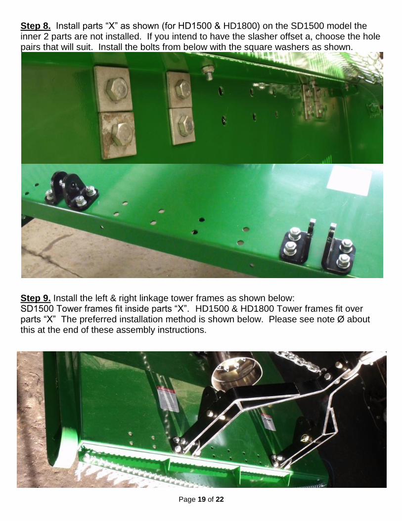
Step 8. Install parts “X” as shown (for HD1500 & HD1800) on the SD1500 model the inner 2 parts are not installed. If you intend to have the slasher offset a, choose the hole pairs that will suit. Install the bolts from below with the square washers as shown.
Step 9. Install the left & right linkage tower frames as shown below: SD1500 Tower frames fit inside parts “X”. HD1500 & HD1800 Tower frames fit over parts “X” The preferred installation method is shown below. Please see note Ø about this at the end of these assembly instructions.
Page 20 of 22
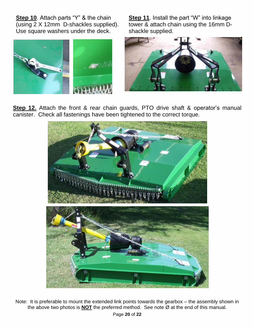
Step 12. Attach the front & rear chain guards, PTO drive shaft & operator’s manual canister. Check all fastenings have been tightened to the correct torque.
Note: It is preferable to mount the extended link points towards the gearbox – the assembly shown in the above two photos is NOT the preferred method. See note Ø at the end of this manual.
Step 10. Attach parts “Y” & the chain (using 2 X 12mm D-shackles supplied). Use square washers under the deck.
Step 11. Install the part “W” into linkage tower & attach chain using the 16mm D-shackle supplied.

Page 21 of 22
COMMISSIONING CHECKLIST
Before this machine can be commissioned you must fill out the checklist in the “Ag-bits MACHINE SAFETY MANUAL, Including: Machine commissioning, Warranty Registration & Policy” – which should accompany this manual. If you do not have a copy of the safety manual contact Ag-bits for a replacement copy. In particular pay attention to the following slasher specific issues, when completing the checklist:
Check oil in gearbox (see page 13).
Check that the PTO shaft & universal joints have been greased (see page 12).
Check the PTO clutch is correctly adjusted (see page 13).
Once again check all fastenings are securely tightened with particular attention to the gearbox & blade fasteners (torque chart, see page 11).
Check the PTO length (see pages 6-8).
RUN UP TEST
With the machine attached to a tractor, perform a run up test by gradually increasing the PTO speed up to 540RPM – listen for any abnormal noises & check for abnormal vibration, do not allow use of the machine until you are satisfied that it is safe to do so.
Note Ø MOUNTING CONFIGURATION
It is preferable to mount the slasher as close as possible to the tractor by installing the linkage tower with the extended link points facing away from the tractor as shown below, in this configuration you will use the un-extended mount points which have pins in the picture below. If the front chain guards are hitting against the tractor wheels then it will be necessary to mount the linkage tower with the extended points towards the tractor & use the link point that gives clearance to the tractor wheels.

Page 22 of 22
Ag-bits Pty
433 Windsor Road VINEYARD NSW 2765 P: (02) 4577 6377 F: (02) 4587 9838 E: [email protected]