operator’s manual libra ultrafast amplifier laser...
TRANSCRIPT
Operator’s ManualLibra Ultrafast AmplifierLaser System
5100 Patrick Henry DriveSanta Clara, CA 95054
Libra Laser Operator’s Manual
This document is copyrighted with all rights reserved. Under the copyrightlaws, this document may not be copied in whole or in part or reproduced inany other media without the express written permission of Coherent, Inc.Permitted copies must carry the same proprietary and copyright notices aswere affixed to the original. This exception does not allow copies to bemade for others, whether or not sold, but all the material purchased maybe sold, given or loaned to another person. Under the law, copyingincludes translation into another language.
Coherent, the Coherent Logo, Positive Light, Libra, Evolution, Legend,Opera, Indigo, Verdi, VItesse, and Mira are registered trademarks ofCoherent, Inc.
Every effort has been made to ensure that the data given in this documentis accurate. The information, figures, tables, specifications and schematicscontained herein are subject to change without notice. Coherent makes nowarranty or representation, either expressed or implied with respect to thisdocument. In no event will Coherent be liable for any direct, indirect,special, incidental or consequential damages resulting from any defects inits documentation.
Technical Support
In the US:
Should you experience any difficulties with your laser or need anytechnical information, please visit our web site www.Coherent.com.Additional support can be obtained by contacting our Technical SupportHotline at 800-367-7890 (408-764-4557 outside the U.S.) or E-mail([email protected]). Telephone coverage is availableMonday through Friday (except U.S. holidays and company shutdowns).
If you call outside our office hours, your call will be taken by our answeringsystem and will be returned when the office reopens.
If there are technical difficulties with your laser that cannot be resolved bysupport mechanisms outlined above, please E-mail or telephone CoherentTechnical Support with a description of the problem and the correctivesteps attempted. When communicating with our Technical SupportDepartment, via the web or telephone, the model and Laser Head serialnumber of your laser system will be required by the Support Engineerresponding to your request.
Outside the U.S.:
If you are located outside the U.S. visit our web site for technicalassistance or contact, by phone, our local Service Representative.Representative phone numbers and addresses can be found on theCoherent web site, www.Coherent.com.
Coherent provides telephone and web technical assistance as a service toits customers and assumes no liability thereby for any injury or damagethat may occur contemporaneous with such services. These supportservices do not affect, under any circumstances, the terms of any warrantyagreement between Coherent and the Buyer. Operation of any Coherentlaser with any of its interlocks defeated is always at the operator's own risk.
ii
Table of Contents
TABLE OF CONTENTS
Preface .................................................................................................................................. ixU.S. Export Control Laws Compliance ................................................................................ ixSymbols Used in this Document and on the System ..............................................................x
Section One: Laser Safety .......................................................................................... 1-1Hazards ............................................................................................................................... 1-1
Optical Safety ............................................................................................................ 1-1Electrical Safety ......................................................................................................... 1-3
Component Lasers .............................................................................................................. 1-4Maximum Accessible Radiation Level............................................................................... 1-4Safety Features and Compliance with Government Requirements .................................... 1-4
Laser Classification.................................................................................................... 1-5Protective Housing..................................................................................................... 1-5Safety Interlocks ........................................................................................................ 1-5Remote Interlock Connector ...................................................................................... 1-5Key Control................................................................................................................ 1-5Laser Radiation Emission Indicators ......................................................................... 1-6Beam Attenuator ........................................................................................................ 1-6Operating Controls..................................................................................................... 1-6Display Screen ........................................................................................................... 1-6Manual Reset Mechanism.......................................................................................... 1-6Location of Safety Labels .......................................................................................... 1-7
Electromagnetic Compatibility ........................................................................................... 1-7Waste Electrical and Electronic Equipment (WEEE, 2002) ............................................... 1-7Sources of Additional Information ................................................................................... 1-10
Laser Safety Standards............................................................................................. 1-10Equipment and Training........................................................................................... 1-10
Section Two: Description and Specifications.................................................. 2-1Libra System ....................................................................................................................... 2-1
Libra Optical Bench Assembly.................................................................................. 2-2Synchronization and Delay Generator (SDG) ........................................................... 2-4Power Supply Assemblies ......................................................................................... 2-4Water Chiller .............................................................................................................. 2-4Laptop Computer ....................................................................................................... 2-4
Specifications...................................................................................................................... 2-4
Section Three: Installation ......................................................................................... 3-1Installation Requirements ................................................................................................... 3-1
Location ..................................................................................................................... 3-1Evolution Pump Laser ............................................................................................... 3-2Vitesse Seed Laser ..................................................................................................... 3-2
Required Utilities ................................................................................................................ 3-2
iii
Libra Laser Operator’s Manual
Unpacking and Inspection .................................................................................................. 3-2Required Tools ........................................................................................................... 3-4First Crate Unpacking Instructions ............................................................................ 3-4Crates 2, 3, & 4 Unpacking Instructions.................................................................... 3-5
Water and Cabling Connections.......................................................................................... 3-5Cooling Water Loop................................................................................................... 3-5Libra Cable Connections ........................................................................................... 3-6Libra Power Connections......................................................................................... 3-10
Grating Installation ........................................................................................................... 3-10External Interlock ............................................................................................................. 3-10
Section Four: Controls and Indicators............................................................... 4-1Vitesse Seed, Evolution Pump, and SDG ........................................................................... 4-1Software Controls ............................................................................................................... 4-1
Section Five: Daily Operation .................................................................................. 5-1Controls and Diagnostics .................................................................................................... 5-2Software Control................................................................................................................. 5-2
Control Computer ...................................................................................................... 5-2Cold System Startup Procedure .......................................................................................... 5-2Shutdown Procedure ........................................................................................................... 5-8Regenerative Amplifier Optimization .............................................................................. 5-11
Pulsewidth Optimization.......................................................................................... 5-12
Section Six: Optical Alignment ............................................................................... 6-1Configuration ...................................................................................................................... 6-1Stretcher Alignment ............................................................................................................ 6-4
Alignment of the Seed Beam to the Stretcher............................................................ 6-5Grating Alignment ..................................................................................................... 6-6Stretcher Mirror Alignment ....................................................................................... 6-8Spatial Chirp-Free Alignment of Stretcher .............................................................. 6-11
RA Alignment Procedure.................................................................................................. 6-13Pre-alignment of RA with HeNe Laser.................................................................... 6-14Final Alignment of RA with Seed Beam ................................................................. 6-16Alignment of the Pump Beam ................................................................................. 6-17RA Optimization Using the Pockels Cells............................................................... 6-19Optimizing Seed Alignment .................................................................................... 6-21Cavity Dumping a Pulse .......................................................................................... 6-22
Compressor Alignment Procedure.................................................................................... 6-23Pre-Alignment of the Compressor Components ...................................................... 6-24
Alignment of the Compressor with the Free- Running RA Beam.................................... 6-25
Section Seven: Maintenance and Troubleshooting ..................................... 7-1Cleaning Optics................................................................................................................... 7-1
Cleaning Installed Optics........................................................................................... 7-2Cleaning Removed Optics ......................................................................................... 7-4Cleaning the Ti:Sapphire Crystal ............................................................................... 7-5
iv
Table of Contents
Stretcher and Compressor Grating, and Stretcher Gold Mirror Cleanliness.............. 7-6Cleaning the Pockels Cells ........................................................................................ 7-6
Troubleshooting .................................................................................................................. 7-7
Section Eight: Basic Theory ...................................................................................... 8-1Ti:Sapphire Laser Theory ................................................................................................... 8-1Chirped Pulse Amplification .............................................................................................. 8-1Pulse Stretching and Compression...................................................................................... 8-2
Libra Pulse Stretcher and Compressor....................................................................... 8-4Regenerative Amplification ................................................................................................ 8-6Bandwidth Detector (BWD) ............................................................................................... 8-8
Overview.................................................................................................................... 8-8
Parts List .............................................................................................................................. A-1
Warranty ...............................................................................................................................B-1Optical Products..................................................................................................................B-1Conditions of Warranty.......................................................................................................B-1Other Products ....................................................................................................................B-2Responsibilities of the Buyer ..............................................................................................B-2Limitations of Warranty ......................................................................................................B-2
Glossary ..................................................................................................................... Glossary-1
Index ................................................................................................................................. Index-1
v
Libra Laser Operator’s Manual
LIST OF FIGURES
1-1. Waste Electrical and Electronic Equipment Label........................................................... 1-71-2. Libra Safety Features and Labels..................................................................................... 1-8
2-1. Libra System .................................................................................................................... 2-12-2. Libra Optical Bench Assembly........................................................................................ 2-3
3-1. First Shipping Crate ......................................................................................................... 3-33-2. Second and Third Shipping Crates .................................................................................. 3-33-3. Fourth Shipping Crate...................................................................................................... 3-43-4. Libra System Water Line Routing ................................................................................... 3-63-5. Libra Optical Bench Assembly Rear Panel Connections ................................................ 3-83-6. SDG Rear Panel Connections .......................................................................................... 3-83-7. External Interlock Circuit .............................................................................................. 3-11
4-1. Evolution Control Panel................................................................................................... 4-24-2. Libra Control Panel.......................................................................................................... 4-44-3. SDG Control Panel .......................................................................................................... 4-64-4. Vitesse Control Panel....................................................................................................... 4-84-5. Spectrometer Control Panel ........................................................................................... 4-10
5-1. Evolution Control ............................................................................................................ 5-45-2. Libra Control.................................................................................................................... 5-55-3. Vitesse Control................................................................................................................. 5-65-4. SDG Control .................................................................................................................... 5-75-5. USB 2000 Spectrometer Control ..................................................................................... 5-85-6. System Operating Software Windows ............................................................................. 5-95-7. Photodiode Signal of Libra Output ................................................................................ 5-115-8. Larger Time Window of Libra Output........................................................................... 5-115-9. Autocorrelation of a Short, Well-Compressed Pulse ..................................................... 5-12
6-1. Optical Layout of Libra ................................................................................................... 6-26-2. Stretcher/Compressor and RA Optical Components ....................................................... 6-36-3. Photo of the Stretcher....................................................................................................... 6-46-4. Rotation Set Screw of Grating Assembly ........................................................................ 6-56-5. Stretcher Grating Alignment for the Zero Order Surface Reflection .............................. 6-66-6. Two 3/32 Balldriver Screws that Lock the Retainer Rings behind the Mirror Mount
are used to Adjust the Grating Rotation in the Vertical Plane ................................... 6-76-7. The Top Spot is the Seed Beam from Vitesse
The Second Stripe is the Beam Reflected from the Gold Mirror .............................. 6-96-8. The Spatially Dispersed Spectrum is Centered on the Folding Mirror............................ 6-96-9. Beam Profiles on the Stretcher Grating ......................................................................... 6-106-10. Four Beams on the Stretcher Grating............................................................................. 6-106-11. Spatial-Chirp-Free Alignment Setup ............................................................................. 6-11
vi
Table of Contents
6-12. Typical Vitesse Spectrum Peak @ 800 nm, FWHM = 12 nm ....................................... 6-126-13. Photo (top) and Layout Diagram (bottom) of the RA Module ...................................... 6-136-14. RA Alignment Using a HeNe Laser .............................................................................. 6-146-15. Typical Scattered Pattern after the Pockels Cell Sandwiched
Between Two Cross-Polarizers ................................................................................ 6-156-16. Adjustment for the Pockels Cell .................................................................................... 6-156-17. Photo (top) and Layout Diagram (bottom) of the RA Module ...................................... 6-176-18. Unseeded Photodiode Signal ......................................................................................... 6-196-19. Cavity Dumped, Unseeded Photodiode Signal.............................................................. 6-206-20. Seeded Photodiode Signal ............................................................................................. 6-206-21. Photodiode Signal of Libra Output Pulse Train............................................................. 6-226-22. Top View of the Compressor ......................................................................................... 6-236-23. Pulse Duration = 90 fs Measured with SSA Using Gaussian Deconvolution ............... 6-246-24. Alignment of the Compressor with Free-Running Laser from RA ............................... 6-256-25. Input Beam on the Compressor Grating ........................................................................ 6-266-26. Input Beam and Spatially Dispersed Spectrum on the Compressor Grating ................. 6-276-27. Typical Four-Beam Pattern on the Compressor Grating................................................ 6-27
7-1. Folding of Lens Tissue..................................................................................................... 7-37-2. Cleaning an Installed Optic.............................................................................................. 7-47-3. Cleaning Removed Optics ............................................................................................... 7-5
8-1. Principle of Chirped Pulse Amplification........................................................................ 8-28-2. Principle of Pulse Stretching............................................................................................ 8-38-3. Principle of Pulse Compression ....................................................................................... 8-38-4. Libra Ti:Sapphire Regenerative Amplifier System ......................................................... 8-48-5. Pulse Stretcher and Compressor Layout .......................................................................... 8-58-6. Side View of the Pulse Stretcher...................................................................................... 8-58-7. RA Optical Components .................................................................................................. 8-6
A-1. Libra 1 kHz Optical Parts Locations............................................................................... A-1
vii
Libra Laser Operator’s Manual
LIST OF TABLES
3-1. Libra Electrical Requirements ......................................................................................... 3-23-2. Rear Panel Connections for the Libra.............................................................................. 3-9
4-1. Evolution Control Panel................................................................................................... 4-34-2. Libra Control Panel.......................................................................................................... 4-54-3. SDG Control Panel .......................................................................................................... 4-64-4. Vitesse Control Panel....................................................................................................... 4-94-5. Spectrometer Control Panel ........................................................................................... 4-10
5-1. Wavelengths of Radiation Generated by the Micra ......................................................... 5-1
7-1. Symptom: Emission Light Is On but No Laser Output ................................................... 7-77-2. Symptom: Libra Output Pulses Do Not Appear to Be
in Sync with Vitesse Operating Frequency...................................................................... 7-87-3. Symptom: SDG Frequency Display Not Showing Laser Operating Frequency ............. 7-87-4. Symptom: BWD Interlock Not Engaging when Vitesse Beam Blocked......................... 7-87-5. Symptom: Power Output from the Libra is Below Specification .................................... 7-97-6. Symptom: Compressed Output Pulse Broader than System Specification.................... 7-107-7. Symptom: Libra Interlock Fault Engaged ..................................................................... 7-107-8. Symptom: Libra Output Unstable.................................................................................. 7-117-9. Symptom: SDG “Sync Error” LED Illuminated although all Necessary Connections
have been Made and the Vitesse Laser is Modelocked and Stable................................ 7-11
A-1. Parts List – Regen Module.............................................................................................. A-2A-2. Parts List – Stretcher/Compressor Module ..................................................................... A-3
viii
Preface
Preface This document contains user information for the LibraTM, an indus-trial one-box ultrafast Ti:Sapphire laser system.
Read this Operator’s Manual carefully before operating thelaser for the first time. Special attention should be given to thematerial in Section One: Laser Safety.
Use of controls or adjustments or performance of proceduresother than those specified in this Operator’s Manual may resultin hazardous radiation exposure.
Use of the system in a manner other than that described hereinmay impair the protection provided by the system.
U.S. Export Control Laws Compliance
It is the policy of Coherent to comply strictly with U.S. exportcontrol laws.
Export and re-export of lasers manufactured by Coherent are subjectto U.S. Export Administration Regulations, which are administeredby the Commerce Department. In addition, shipments of certaincomponents are regulated by the State Department under the Inter-national Traffic in Arms Regulations.
The applicable restrictions vary depending on the specific productinvolved and its destination. In some cases, U.S. law requires thatU.S. Government approval be obtained prior to resale, export orre-export of certain articles. When there is uncertainty about theobligations imposed by U.S. law, clarification should be obtainedfrom Coherent or an appropriate U.S. Government agency.
ix
Libra Laser Operator’s Manual
Symbols Used in this Document and on the System
This symbol is intended to alert the operator to the presence ofdangerous voltages associated with the laser that may be of suffi-cient magnitude to constitute a risk of electric shock.
This symbol is intended to alert the operator to the presence ofimportant operating and maintenance instructions.
This symbol is intended to alert the operator to the danger ofexposure to hazardous visible and invisible laser radiation.
~ ALTERNATING CURRENT.
OFF OR STOP.
ON OR START.
x
Laser Safety
SECTION ONE: LASER SAFETY
This user information is in compliance with section 1040.10 ofthe CDRH Performance Standards for Laser Products from theHealth and Safety Act of 1968.
Use of controls or adjustments or performance of proceduresother than those specified herein may result in hazardous radi-ation exposure.
This laser safety section must be reviewed thoroughly prior to oper-ating the Libra laser system. Safety instructions presentedthroughout this manual must be followed carefully.
Hazards Hazards associated with lasers generally fall into the following cate-gories:
• Exposure to laser radiation that may damage the eyes or skin
• Electrical hazards generated in the laser power supply or asso-ciated circuits
• Chemical hazards resulting from contact of the laser beamwith volatile or flammable substances, or released as a resultof laser material processing
The above list is not intended to be exhaustive. Anyone operatingthe laser must consider the interaction of the laser system with itsspecific working environment to identify potential hazards.
Optical Safety Laser light, because of its special qualities, poses safety hazards notassociated with light from conventional sources. The safe use oflasers requires all operators, and everyone near the laser system, tobe aware of the dangers involved. Users must be familiar with theinstrument and the properties of coherent, intense beams of light.
The safety precautions listed below are to be read and observed byanyone working with or near the laser. At all times, ensure that allpersonnel who operate, maintain or service the laser are protected
1 - 1
Libra Laser Operator’s Manual
from accidental or unnecessary exposure to laser radiationexceeding the accessible emission limits listed in ‘PerformanceStandards for Laser Products,’ United States Code of Federal Regu-lations, 21CFR1040 10(d).
Direct eye contact with the output beam from the laser will causeserious damage and possible blindness.
The greatest concern when using a laser is eye safety. In addition tothe main beam, there are often many smaller beams present atvarious angles near the laser system. These beams are formed byspecular reflections of the main beam at polished surfaces such aslenses or beamsplitters. While weaker than the main beam, suchbeams may still be sufficiently intense to cause eye damage.
Laser beams are powerful enough to burn skin, clothing or painteven at some distance. They can ignite volatile substances such asalcohol, gasoline, ether and other solvents, and can damagelight-sensitive elements in video cameras, photomultipliers andphotodiodes. The user is advised to follow the precautions below.
Recommended Precautions and Guidelines
1. Observe all safety precautions in the preinstallation and oper-ator’s manuals.
2. All personnel should wear laser safety glasses rated to protectagainst the specific wavelengths being generated. Protectiveeye wear vendors are listed in the Laser Focus World, Lasersand Optronics, and Photonics Spectra Buyer’s guides. Consultthe ANSI, ACGIH, or OSHA standards listed at the end of thissection for guidance.
3. Avoid wearing watches, jewelry, or other objects that mayreflect or scatter the laser beam.
4. Stay aware of the laser beam path, particularly when externaloptics are used to steer the beam.
5. Provide enclosures for beam paths whenever possible.
6. Use appropriate energy-absorbing targets for beam blocking.
7. Block the beam before applying tools such as Allen wrenchesor ball drivers to external optics.
8. Limit access to the laser to qualified users who are familiarwith laser safety practices. When not in use, lasers should beshut down completely and made off-limits to unauthorizedpersonnel.
1 - 2
Laser Safety
9. Use the laser in an enclosed room. Laser light can remain colli-mated over long distances and therefore presents a potentialhazard if not confined. It is good practice to operate the laserin a room with controlled access.
10. Post warning signs in the area of the laser beam to alert thosepresent.
11. Exercise extreme caution when using solvents in the area ofthe laser.
12. Never look directly into the laser light source or at scatteredlaser light from any reflective surface. Never sight down thebeam.
13. Set up the laser so that the beam height is either well below orwell above eye level.
14. Avoid direct exposure to the laser light. Laser beams can easilycause flesh burns or ignite clothing.
15. Advise all those working with or near the laser of these precau-tions.
Laser safety glasses protect the user from eye damage byblocking light at the laser wavelengths. However, this alsoprevents the operator from seeing the beam. Exercise extremecaution even while wearing safety glasses.
Electrical Safety
Normal operation of the Libra should not require access to thepower supply circuitry. Removing the power supply cover willexpose the user to potentially lethal electrical hazards. Contactan authorized service representative before attempting tocorrect any problem with the power supply.
Recommended Precautions and Guidelines
The following precautions must be observed by everyone whenworking with potentially hazardous electrical circuitry:
1. Disconnect main power lines before working on any electricalequipment when it is not necessary for the equipment to beoperating.
1 - 3
Libra Laser Operator’s Manual
2. Do not short or ground the power supply output. Protectionagainst possible hazards requires proper connection of theground terminal on the power cable, and an adequate externalground. Check these connections at the time of installation,and periodically thereafter.
3. Never work on electrical equipment unless there is anotherperson nearby who is familiar with the operation and hazardsof the equipment, and who is competent to administer first aid.
4. When possible, keep one hand away from the equipment toreduce the danger of current flowing through the body if a livecircuit is touched accidentally.
5. Always use approved, insulated tools.
6. Special measurement techniques are required for this system.A technician who has a complete understanding of the systemoperation and associated electronics must select ground refer-ences.
Component Lasers
The Libra system incorporates Coherent VitesseTM and Evolu-tionTM lasers as components. The beams from these lasers arehazardous. Refer to their respective Operator’s Manuals for addi-tional safety information.
Maximum Accessible Radiation Level
The Libra and its component lasers produce visible and invisibleradiation over a wavelength range of 500 to 1100 nm, with amaximum of 40 Watts continuous wave power, and < 5 Wattsmaximum energy per 30 femtosecond to 6 picosecond pulse[CFR 1040.10 (h)(2)/ EN 60825-1/ IEC 608225-1, Clause 6].
Safety Features and Compliance with Government Requirements
The following features are incorporated into the instrument toconform to several government requirements. The applicable UnitedStates Government requirements are contained in 21 CFR,Subchapter J, part 1040 administered by the Center for Devices andRadiological Health (CDRH). The European Community require-ments for product safety are specified in the Low Voltage Directive(LVD) (published in 73/23/EEC and amended in 93/68/EEC). TheLow Voltage Directive requires that lasers comply with the standardEN 61010-1/IEC 61010-1 “Safety Requirements For ElectricalEquipment For Measurement, Control and Laboratory Use” andEN 60825-1/IEC 60825-1 “Safety of Laser Products”. Complianceof this laser with the LVD requirements is certified by the CE mark.
1 - 4
Laser Safety
Laser Classification
Governmental standards and requirements specify that the lasermust be classified according to the output power or energy and thelaser wavelength. The Libra is classified as Class IV based on 21CFR, Subchapter J, part 1040, section 1040.10 (d). According to theEuropean Community standards, Libra lasers are classified asClass 4 based on EN 60825-1, clause 9. In this manual, the classifi-cation will be referred to as Class 4.
Protective Housing The laser head is enclosed in a protective housing that preventshuman access to radiation in excess of the limits of Class I radiationas specified in the 21CFR, Part 1040 Section 1040.10 (f)(1) andTable 1-A/EN 60825-1/IEC 60825-1 clause 4.2 except for theoutput beam, which is Class 4.
Safety Interlocks The system incorporates multiple safety interlocks which activatewhen the top cover of the Vitesse, Evolution, or any one of the threetop covers of the Libra is removed. An interlock fault initiation willterminate all lasing by activating a shutter mechanism as well asremoving power from the infrared diode lasers in each power supply.While installed, the interlock defeats are directly visible by anyonenear the laser. It is not possible to replace the laser cover while theinterlocks are installed
The laser interlocks should be defeated only for the purpose of main-tenance and service by trained personnel aware of the hazardsinvolved. Extreme caution must always be observed when operatingthe laser with its covers removed. [CFR 1040.10 (f)(2)/EN 60825-1/IEC 608225-1, Clause 4.3].
Laser Radiation Emission Indicators
The LASER EMISSION LED on the laser head illuminates approx-imately 30 seconds before laser emission can occur. The indicator isvisible without exposing the operator to laser emission. Amber lightis used which is visible while wearing the proper type of safetyglasses [CFR 1040.10(f)(5)/EN 60825-1/IEC 60825-1, clause 4.6].
Beam Attenuator An internal shutter prevents exposure to all laser radiation withoutremoving power from the system [CFR 1040.10 (f)(6)/EN60825-1/IEC 60825-1, clause 4.7].
1 - 5
Libra Laser Operator’s Manual
Operating Controls
The laser controls are positioned so that the operator is not exposedto laser emission while manipulating the controls [CFR1040.10(f)(7)/EN 60825-1/IEC 60825-1, clause 4.8].
Manual Reset Mechanism
Following an interlock fault or unexpected loss of electrical power,laser operation requires manual clearing of the fault condition(s)[CFR 1040.10(f)(10)/EN 60825-1/IEC 60825-1, clause 4.11].
Use of controls or adjustments or performance of proceduresother than those specified in the manual may result in hazardousradiation exposure.
Use of the system in a manner other than that described hereinmay impair the protection provided by the system.
Location of Safety Labels
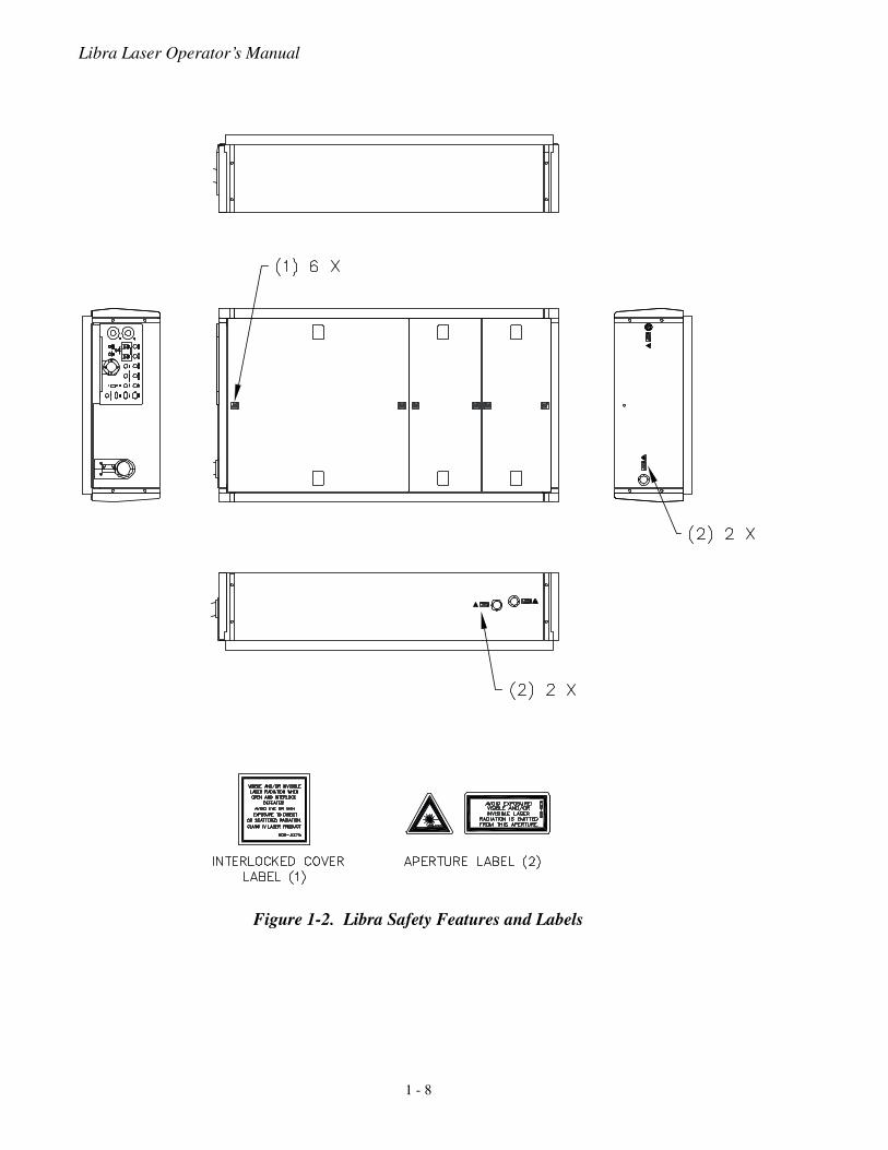
Refer to Figure 1-2 for the location of all safety labels. These includewarning labels indicating removable or displaceable protectivehousings, apertures through which laser radiation is emitted, andlabels of certification and identification [CFR 1040.10(g), CFR1040.2, and CFR 1010.3/ EN 60825-1/IEC 60825-1, Clause 5].
Electromagnetic Compatibility
The European requirements for Electromagnetic Compliance(EMC) are specified in the EMC Directive (published in89/336/EEC).
Conformance to the EMC requirements is achieved through compli-ance with the harmonized standards EN55011 (1991) for emissionand ENC50082-1 (1992) for immunity.
The laser meets the emission requirements for Class B, group 1 asspecified in EN55011 (1991).
Compliance of this laser with the EMC requirements is certified bythe CE mark.
1 - 6
Laser Safety
Waste Electrical and Electronic Equipment (WEEE, 2002)
The European Waste Electrical and Electronic Equipment (WEEE)Directive (2002/96/EC) is represented by a crossed-out garbagecontainer label (see Figure 1-1). The purpose of this directive is tominimize the disposal of WEEE as unsorted municipal waste and tofacilitate its separate collection.
Figure 1-1. Waste Electrical and Electronic Equipment Label
1 - 7
Libra Laser Operator’s Manual
Figure 1-2. Libra Safety Features and Labels
1 - 8
Laser Safety
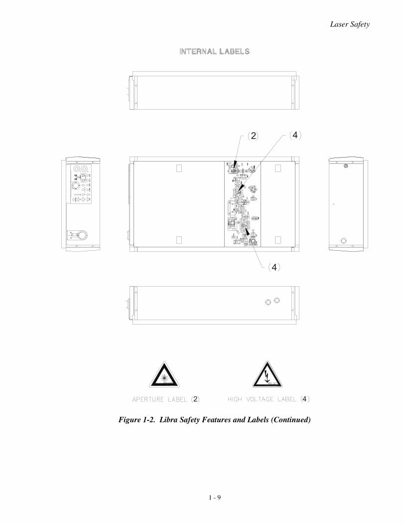
Figure 1-2. Libra Safety Features and Labels (Continued)
�
�
�
�
�
1 - 9
Libra Laser Operator’s Manual
Sources of Additional Information
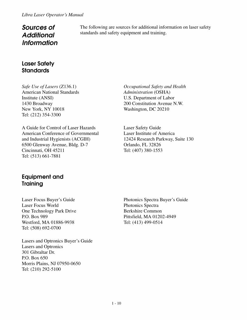
The following are sources for additional information on laser safetystandards and safety equipment and training.
Laser Safety Standards
Equipment and Training
Safe Use of Lasers (Z136.1)American National StandardsInstitute (ANSI)1430 BroadwayNew York, NY 10018Tel: (212) 354-3300
Occupational Safety and HealthAdministration (OSHA)U.S. Department of Labor200 Constitution Avenue N.W.Washington, DC 20210
A Guide for Control of Laser HazardsAmerican Conference of Governmentaland Industrial Hygienists (ACGIH)6500 Glenway Avenue, Bldg. D-7Cincinnati, OH 45211Tel: (513) 661-7881
Laser Safety GuideLaser Institute of America12424 Research Parkway, Suite 130Orlando, FL 32826Tel: (407) 380-1553
Laser Focus Buyer’s GuideLaser Focus WorldOne Technology Park DriveP.O. Box 989Westford, MA 01886-9938Tel: (508) 692-0700
Photonics Spectra Buyer’s GuidePhotonics SpectraBerkshire CommonPittsfield, MA 01202-4949Tel: (413) 499-0514
Lasers and Optronics Buyer’s GuideLasers and Optronics301 Gibraltar Dr.P.O. Box 650Morris Plains, NJ 07950-0650Tel: (210) 292-5100
1 - 10
Description and Specifications
SECTION TWO: DESCRIPTION AND SPECIFICATIONS
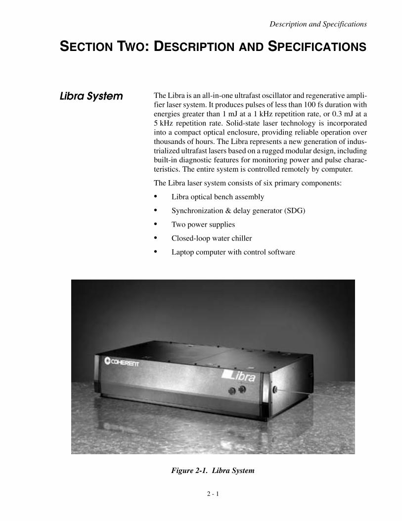
Libra System The Libra is an all-in-one ultrafast oscillator and regenerative ampli-fier laser system. It produces pulses of less than 100 fs duration withenergies greater than 1 mJ at a 1 kHz repetition rate, or 0.3 mJ at a5 kHz repetition rate. Solid-state laser technology is incorporatedinto a compact optical enclosure, providing reliable operation overthousands of hours. The Libra represents a new generation of indus-trialized ultrafast lasers based on a rugged modular design, includingbuilt-in diagnostic features for monitoring power and pulse charac-teristics. The entire system is controlled remotely by computer.
The Libra laser system consists of six primary components:
• Libra optical bench assembly
• Synchronization & delay generator (SDG)
• Two power supplies
• Closed-loop water chiller
• Laptop computer with control software
Figure 2-1. Libra System
2 - 1
Libra Laser Operator’s Manual
Libra Optical Bench Assembly
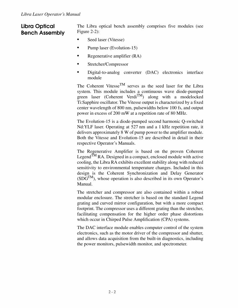
The Libra optical bench assembly comprises five modules (seeFigure 2-2):
• Seed laser (Vitesse)
• Pump laser (Evolution-15)
• Regenerative amplifier (RA)
• Stretcher/Compressor
• Digital-to-analog converter (DAC) electronics interfacemodule
The Coherent VitesseTM serves as the seed laser for the Librasystem. This module includes a continuous wave diode-pumpedgreen laser (Coherent VerdiTM) along with a modelockedTi:Sapphire oscillator. The Vitesse output is characterized by a fixedcenter wavelength of 800 nm, pulsewidths below 100 fs, and outputpower in excess of 200 mW at a repetition rate of 80 MHz.
The Evolution-15 is a diode-pumped second harmonic Q-switchedNd:YLF laser. Operating at 527 nm and a 1 kHz repetition rate, itdelivers approximately 8 W of pump power to the amplifier module.Both the Vitesse and Evolution-15 are described in detail in theirrespective Operator’s Manuals.
The Regenerative Amplifier is based on the proven CoherentLegendTM RA. Designed in a compact, enclosed module with activecooling, the Libra RA exhibits excellent stability along with reducedsensitivity to environmental temperature changes. Included in thisdesign is the Coherent Synchronization and Delay Generator(SDGTM), whose operation is also described in its own Operator’sManual.
The stretcher and compressor are also contained within a robustmodular enclosure. The stretcher is based on the standard Legendgrating and curved mirror configuration, but with a more compactfootprint. The compressor uses a different grating than the stretcher,facilitating compensation for the higher order phase distortionswhich occur in Chirped Pulse Amplification (CPA) systems.
The DAC interface module enables computer control of the systemelectronics, such as the motor driver of the compressor and shutter,and allows data acquisition from the built-in diagnostics, includingthe power monitors, pulsewidth monitor, and spectrometer.
2 - 2
Description and Specifications
Figure 2-2. Libra Optical Bench Assembly
���������� ���������
������� �� ����������
��������������
��� ������
2 - 3
Libra Laser Operator’s Manual
Synchronization and Delay Generator (SDG)
The SDG controls the precise timing of the RA Pockels cells. Itcontains a high-speed power supply for the Pockels cells as well asa bandwidth detector (BWD) circuit, which serves as an interlock toprotect the laser from operation at narrow bandwidth.
Power Supply Assemblies
The Libra system includes two individual power supplies, for theVitesse and Evolution-15 modules. Refer to the Vitesse and Evolu-tion-15 Operator’s Manuals for additional details.
Water Chiller The closed-loop water chiller dissipates the heat generated by thesystem and stabilizes the Evolution-15, Vitesse and RA. The temper-ature is optimized in the factory and is typically within the range of18 to 21° C. Refer to the chiller operator’s manual for further details.
Laptop Computer The system is shipped with a laptop computer with Windows-basedcontrol software already installed. The Vitesse and SDG arecontrolled via a serial RS-232 interface. The Evolution-15, inte-grated spectrometer and DAC electronics module are controlledthrough Universal Serial Bus (USB). A four-port USB-to-RS-232converter and USB hub are included with the system.
Specifications The Customer Data Sheet shipped with each Libra provides adetailed description of system performance. Specifications for allCoherent products can be found at www.Coherent.com.
2 - 4
Installation and Utility Requirements
SECTION THREE: INSTALLATION
Read this manual thoroughly before installation. It is important tobecome familiar with all aspects of installation and operation of theLibra, especially with the safety guidelines presented throughoutthis manual.
The information in this section is provided for reference only. Donot attempt to install the laser or remove the lid sealing the lasercavity without an authorized service representative present.Either action, if unauthorized, will void the warranty.
Call an authorized service representative to arrange an installa-tion appointment, which is included as part of the purchaseagreement. Before installation, unpack and locate the laser inthe area in which it will be used.
Installation Requirements
Some planning is required before installing the Libra:
• Select a suitable location for the Libra.
• Ensure sufficient utilities are available.
• Have the appropriate diagnostic equipment readily available.
Location The Libra must rest on an optical table. Coherent recommends thatthe Libra be located in a laboratory environment; that is, in a roomfree of dust, drafts, and which does not exhibit large temperaturefluctuations. Although the Libra is designed to be insensitive toenvironment temperature, Coherent recommends that the tempera-ture be controlled within ± 2 ° C throughout the day for optimalsystem performance.
The Libra requires a minimum table space of about 4 x 3 ft.(1.2 x 0.90 m). It is the responsibility of the customer to determinethe best location for the Libra. The Libra must be placed in a positionthat allows easy access for service-related activities.
3 - 1
Libra Laser Operator’s Manual
Evolution Pump Laser
Refer to the Evolution Operator’s Manual for a detailed descriptionof the installation of the Evolution.
Vitesse Seed Laser Refer to the Vitesse Operator’s Manual for a detailed description ofthe installation of the Vitesse.
Required Utilities The electrical requirements for the Libra are found in Table 3-1.Additional requirements for the Vitesse and Evolution are found intheir respective manuals.
Unpacking and Inspection
The Libra was packed with great care and its containers inspectedprior to shipment. Upon receiving the system, immediately inspectthe outside of all containers to ensure no damage occurred in transit.If there appears to be visible damage (holes in the containers, waterdamage, crushing, etc.), immediately notify Coherent and a repre-sentative of the carrier. Request that a representative of the carrier bepresent when unpacking the contents.
The Libra system, when shipped from the factory, is shipped in fourcrates:
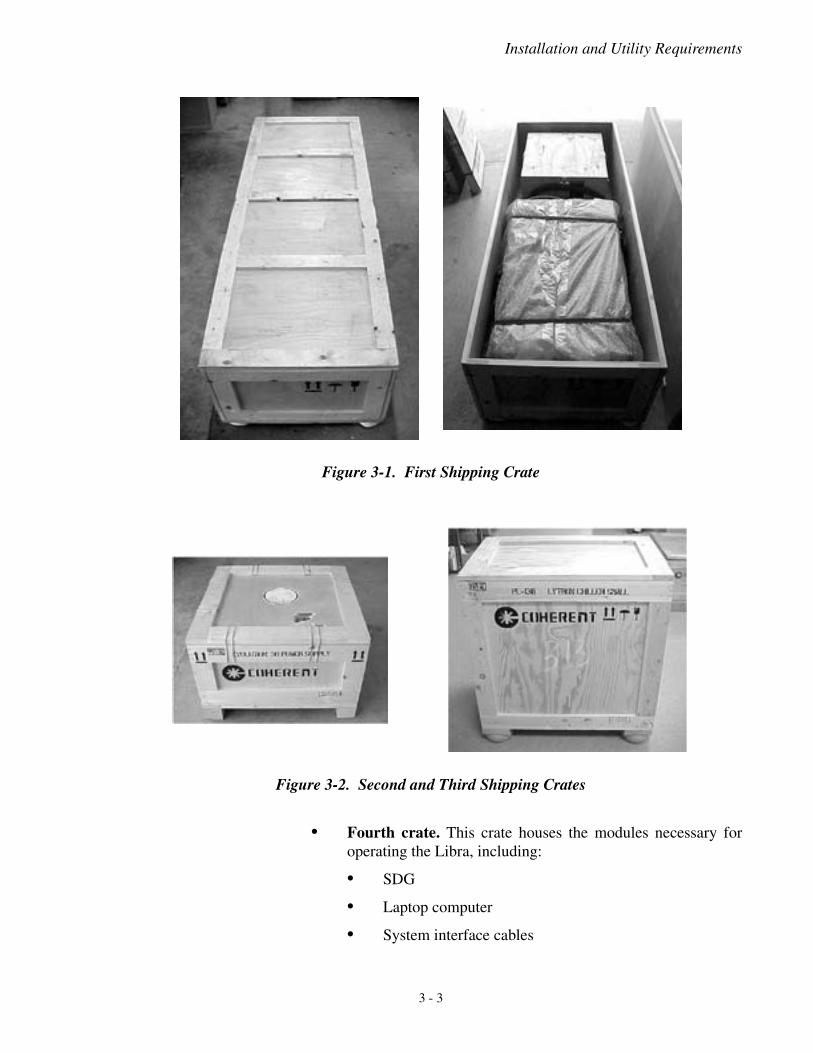
• First crate. This crate is divided into two main sections. Onesection houses the Vitesse Power Supply and the other housesthe entire Libra optical bench.
• Second crate. This crate houses the Evolution Power Supply.
• Third crate. This crate houses the system chiller with waterhoses attached.
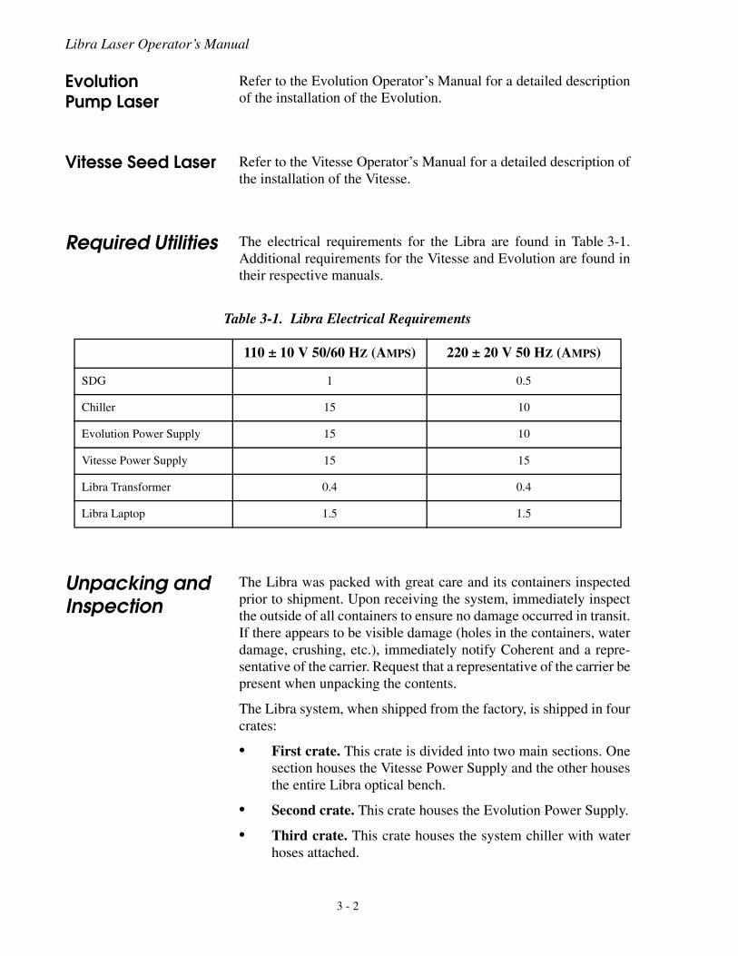
Table 3-1. Libra Electrical Requirements
110 ± 10 V 50/60 HZ (AMPS) 220 ± 20 V 50 HZ (AMPS)
SDG 1 0.5
Chiller 15 10
Evolution Power Supply 15 10
Vitesse Power Supply 15 15
Libra Transformer 0.4 0.4
Libra Laptop 1.5 1.5
3 - 2
Installation and Utility Requirements
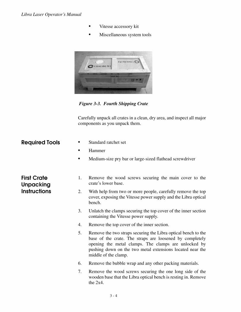
• Fourth crate. This crate houses the modules necessary foroperating the Libra, including:
• SDG
• Laptop computer
• System interface cables
Figure 3-1. First Shipping Crate
Figure 3-2. Second and Third Shipping Crates
3 - 3
Libra Laser Operator’s Manual
• Vitesse accessory kit
• Miscellaneous system tools
Carefully unpack all crates in a clean, dry area, and inspect all majorcomponents as you unpack them.
Required Tools • Standard ratchet set
• Hammer
• Medium-size pry bar or large-sized flathead screwdriver
First Crate Unpacking Instructions
1. Remove the wood screws securing the main cover to thecrate’s lower base.
2. With help from two or more people, carefully remove the topcover, exposing the Vitesse power supply and the Libra opticalbench.
3. Unlatch the clamps securing the top cover of the inner sectioncontaining the Vitesse power supply.
4. Remove the top cover of the inner section.
5. Remove the two straps securing the Libra optical bench to thebase of the crate. The straps are loosened by completelyopening the metal clamps. The clamps are unlocked bypushing down on the two metal extensions located near themiddle of the clamp.
6. Remove the bubble wrap and any other packing materials.
7. Remove the wood screws securing the one long side of thewooden base that the Libra optical bench is resting in. Removethe 2x4.
Figure 3-3. Fourth Shipping Crate
3 - 4
Installation and Utility Requirements
8. Using the necessary personnel, remove the laser benchassembly and its attached Vitesse umbilical and Power Supplyfrom the crate.
9. Carefully set the laser equipment on a firm, flat surface, suchas an optical table.
Crates 2, 3, & 4 Unpacking Instructions
1. Remove the wood screws from crate 3 (chiller) and the clampsfrom crates 2 and 4.
2. Remove all the covers.
3. Proceed in unpacking the crates in a fashion similar to the firstcrate.
Water and Cabling Connections
Cooling Water Loop
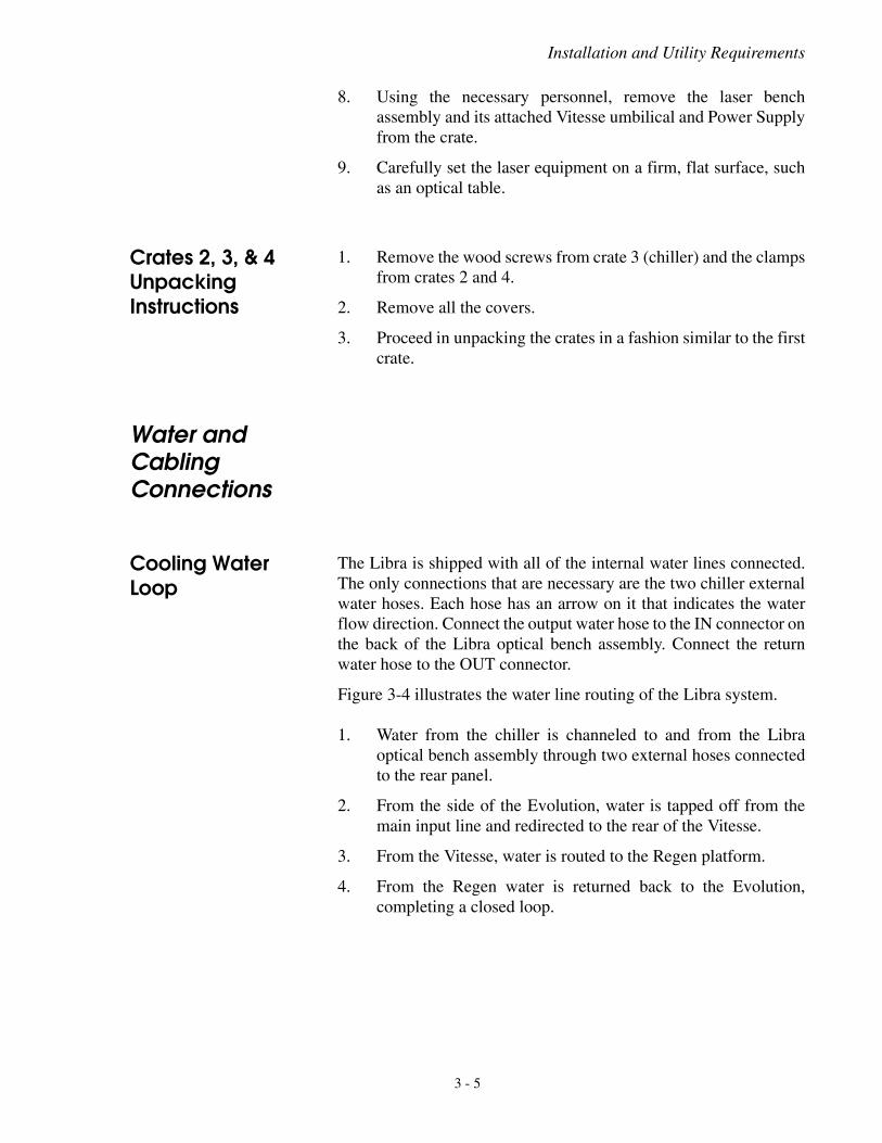
The Libra is shipped with all of the internal water lines connected.The only connections that are necessary are the two chiller externalwater hoses. Each hose has an arrow on it that indicates the waterflow direction. Connect the output water hose to the IN connector onthe back of the Libra optical bench assembly. Connect the returnwater hose to the OUT connector.
Figure 3-4 illustrates the water line routing of the Libra system.
1. Water from the chiller is channeled to and from the Libraoptical bench assembly through two external hoses connectedto the rear panel.
2. From the side of the Evolution, water is tapped off from themain input line and redirected to the rear of the Vitesse.
3. From the Vitesse, water is routed to the Regen platform.
4. From the Regen water is returned back to the Evolution,completing a closed loop.
3 - 5
Libra Laser Operator’s Manual
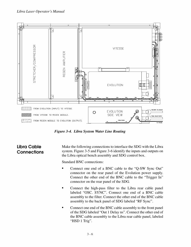
Libra Cable Connections
Make the following connections to interface the SDG with the Librasystem. Figure 3-5 and Figure 3-6 identify the inputs and outputs onthe Libra optical bench assembly and SDG control box.
Standard BNC connections:
• Connect one end of a BNC cable to the “Q-SW Sync Out”connector on the rear panel of the Evolution power supply.Connect the other end of the BNC cable to the “Trigger In”connector on the rear panel of the SDG.
• Connect the high-pass filter to the Libra rear cable panellabeled “OSC. SYNC”. Connect one end of a BNC cableassembly to the filter. Connect the other end of the BNC cableassembly to the back panel of SDG labeled “RF Sync”.
• Connect one end of the BNC cable assembly to the front panelof the SDG labeled “Out 1 Delay ns”. Connect the other end ofthe BNC cable assembly to the Libra rear cable panel, labeled“HSD 1 Trig”.
Figure 3-4. Libra System Water Line Routing
3 - 6
Installation and Utility Requirements
• Connect one end of a BNC cable assembly to the front panelof the SDG labeled “Out 2 Delay ns”. Connect the other end ofthe BNC cable assembly to the Libra rear cable panel labeled“HSD 2 Trig”.
• Connect one end of a BNC cable assembly to the front panelof the SDG labeled “Sync out Delay ns”. Connect the other endthe BNC cable assembly to the trigger input of an Oscillo-scope. This trigger and the "Regen Build-Up" output (locatedat the back of the Libra) are used to monitor the RegenIntra-Cavity buildup during system operation. Set the timebase to 100 or 200 ns per division.
High Voltage BNC connections:
• Connect one end of the High-Voltage BNC cable assembly tothe back panel of the SDG labeled “High Voltage H.V. 1”.Connect the other end the High-Voltage BNC cable assemblyto the Libra rear cable panel labeled “High Voltage HSD 1”.
• Connect one end of the High Voltage BNC cable assembly tothe back panel of the SDG labeled “High Voltage H.V. 2”.Connect the other end the High-Voltage BNC cable assemblyto the Libra rear cable panel labeled “High Voltage HSD 2”.
Remaining Cables:
• Connect one end of the BWD interface cable assembly to theLibra rear cable panel connector labeled “BWD.” Connect theother end of the BWD interface cable assembly to the rearpanel of the SDG also labeled “BWD.” The toggle switch onthe SDG rear panel should be set to ON (flipped up).
• Connect one end of the RS-232 D-sub cable to the rear panelof the SDG labeled “RS-232”. Connect the other end of theRS-232 D-sub cable to the Libra rear cable panel labeled“SDG.”
• Connect one end of the RS-232 D-sub cable to the rear panelof the Vitesse labeled “RS-232.” Connect the other end of theRS-232 D-sub cable to the Libra rear cable panel labeled“VITESSE.”
• Connect one end of the USB cable to the rear panel of theLibra. Connect the other end to the Laptop.
• Connect one end of the USB cable to the front panel of theEvolution. Connect the other end to the Laptop.
• Connect one end of the fiber optic cable to the Spectrometerinput. Connect the other end to either the output spectrum orthe seed spectrum. This second connection can be changed asnecessary.
3 - 7
Libra Laser Operator’s Manual
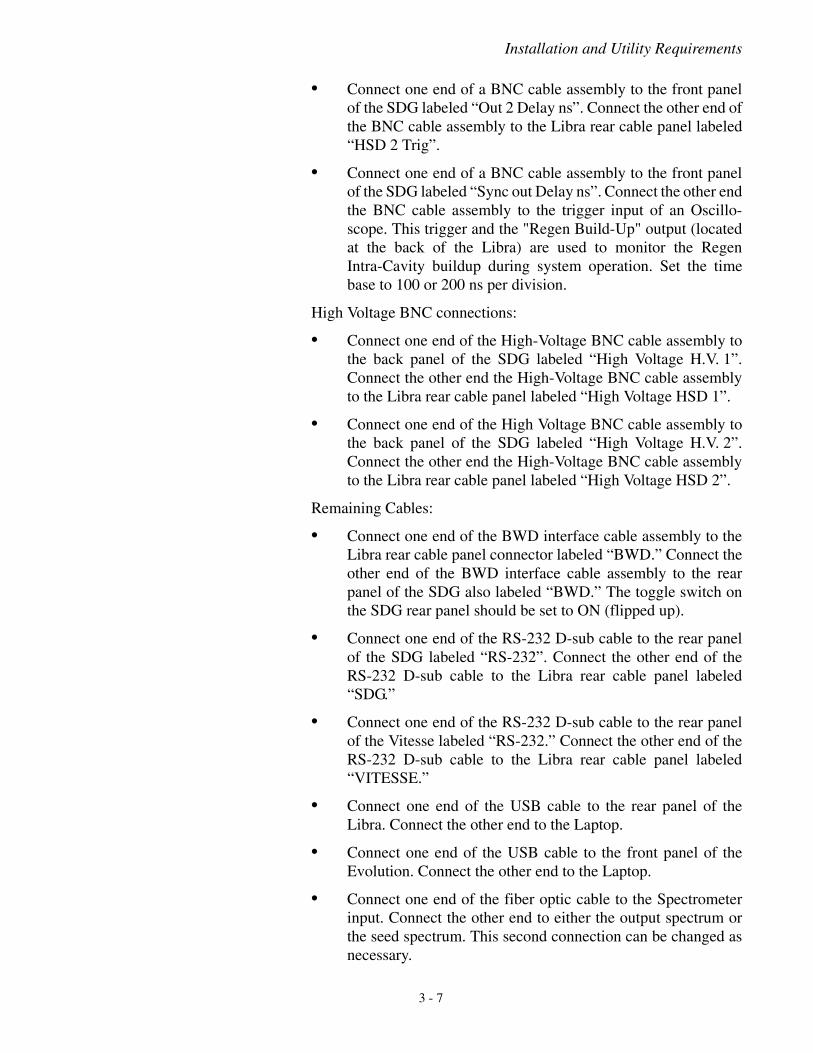
Figure 3-5. Libra Optical Bench Assembly Rear Panel Connections
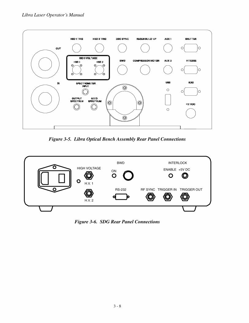
Figure 3-6. SDG Rear Panel Connections
HIGH VOLTAGE
H.V. 2
H.V. 1
BWD
ON
RS-232
INTERLOCK
ENABLE +5V DC
TRIGGER IN TRIGGER OUTRF SYNC
3 - 8
Installation and Utility Requirements
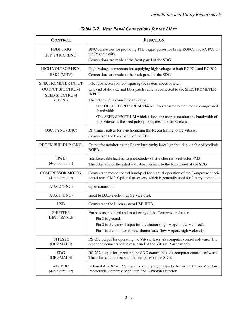
Table 3-2. Rear Panel Connections for the Libra
CONTROL FUNCTION
HSD1 TRIG
HSD 2 TRIG (BNC)
BNC connectors for providing TTL trigger pulses for firing RGPC1 and RGPC2 of the Regen cavity.
Connections are made at the front panel of the SDG.
HIGH VOLTAGE HSD1
HSD2 (MHV)
High Voltage connectors for supplying high voltage to both RGPC1 and RGPC2.
Connections are made at the back panel of the SDG.
SPECTROMETER INPUT
OUTPUT SPECTRUM
SEED SPECTRUM (FC/PC)
Fiber connectors for configuring the system spectrometer.
One end of the external fiber patch cable is connected to the SPECTROMETER INPUT.
The other end is connected to either:
•The OUTPUT SPECTRUM which allows the user to monitor the compressed bandwidth
•The SEED SPECTRUM which allows the user to monitor the bandwidth of the Vitesse as the seed pulse propagates into the Stretcher
OSC. SYNC (BNC) RF trigger pulses for synchronizing the Regen timing to the Vitesse.
Connects to the back panel of the SDG.
REGEN BUILDUP (BNC) Output for monitoring the Regen intracavity laser light buildup via fast photodiode RGPD1.
BWD (4-pin circular)
Interface cable leading to photodiodes of stretcher retro-reflector SM3.
The other end of the interface cable connects to the back panel of the SDG.
COMPRESSOR MOTOR (4-pin circular)
Connects to motor control hand-pad for manual operation of the Compressor hori-zontal retro CM2. Optional accessory which is generally used for factory operation.
AUX 2 (BNC) Open connector.
AUX 1 (BNC) Input to DAQ electronics (service use).
USB Connects to the Libra system USB HUB.
SHUTTER (DB9 FEMALE)
Enables user control and monitoring of the Compressor shutter:
Pin 3 is ground.
Pin 2 is the control input for the shutter (high = open, low = closed).
Pin 1 is the monitor for the shutter state (low = open, high = closed).
VITESSE (DB9 MALE)
RS-232 output for operating the Vitesse laser via computer control software. The other end connects to the rear panel of the Vitesse Power supply.
SDG (DB9 MALE)
RS-232 output for operating the SDG control box via computer control software. The other end connects to the rear panel of the SDG.
+12 VDC (4-pin circular)
External AC/DC + 12 V input for supplying voltage to the system Power Monitors, Photodiode, compressor shutter, and 2-Photon Detector.
3 - 9
Libra Laser Operator’s Manual
Libra Power Connections
Connect the following equipment to facility power:
• SDG
• Vitesse
• Evolution
• Chiller
• Laptop
• Libra 15V Power Supply
Grating Installation
The Libra is shipped with the stretcher and compressor gratings inseparate containers. The gratings are installed by Coherent fieldservice engineers or representatives. The grating alignment proce-dure is described in “Section Six: Optical Alignment”.
External Interlock
An external interlock connector is provided on the SDG rear panel.When the toggle switch is in the ENABLE position (up), the systemwill not operate with this circuit open. In the event of an interlockfault during normal operation, the shutter inside the Libra head isclosed and the pump lasers are disabled. This circuit may be disabledby toggling the switch down.
Alternatively, the interlock connector may be wired to an externalcircuit such as a door switch. Many types of switches may be used,but the switch should have its contacts closed when it is safe tooperate the laser and open when it is not safe.
To incorporate an external safety interlock circuit into the lasersystem, perform the following steps:
1. The laser should be in either the “OFF” or “STANDBY” state(See Section Five: Operation). Remove the interlock defeatfrom the back of the power supply. This type of connector iscalled a “three pin mini-DIN”.
2. Slide the plastic cover off of the connector, and locate the twopins that have a wire soldered between them. These are pins 1and 2. Remove the shorting wire and solder the interlock wiresto these two pins. Make sure the wires have adequate strainrelief.
3. Solder the other ends of the wires to an interlock switch.
Figure 3-7 shows the wiring diagram for the switch. One wire runsfrom pin 1 of the connector to the normally open contact of the
3 - 10

Installation and Utility Requirements
switch. The other wire runs from pin 2 to the common terminal ofthe switch. The switch is shown in the open position, which is thecondition where the laser will not operate.
Figure 3-7. External Interlock Circuit
3 - 11

Libra Laser Operator’s Manual
3 - 12
Controls and Indicators
SECTION FOUR: CONTROLS AND INDICATORS
Vitesse Seed, Evolution Pump, and SDG
The Vitesse and Evolution lasers, as well as the Synchronization andDelay Generator (SDG), are described in detail in separate Oper-ator’s Manuals. Refer to these for descriptions of their controls andindicators.
Software Controls
The following figures depict the software control panels, while thetables describe the buttons and indicators in greater detail.
4 - 1
Libra Laser Operator’s Manual
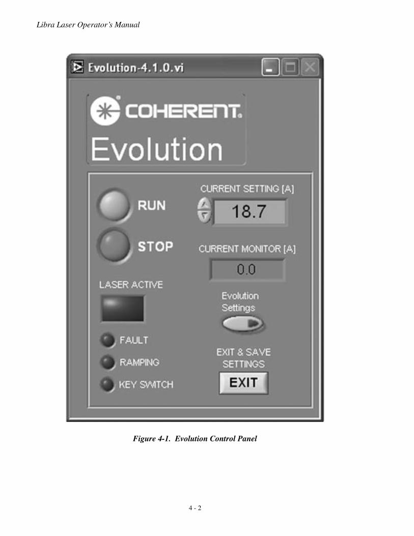
Figure 4-1. Evolution Control Panel
4 - 2
Controls and Indicators
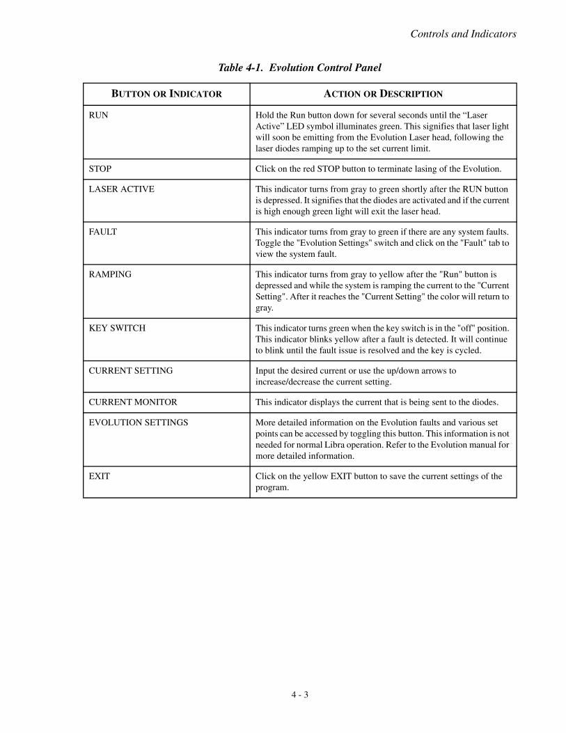
Table 4-1. Evolution Control Panel
BUTTON OR INDICATOR ACTION OR DESCRIPTION
RUN Hold the Run button down for several seconds until the “Laser Active” LED symbol illuminates green. This signifies that laser light will soon be emitting from the Evolution Laser head, following the laser diodes ramping up to the set current limit.
STOP Click on the red STOP button to terminate lasing of the Evolution.
LASER ACTIVE This indicator turns from gray to green shortly after the RUN button is depressed. It signifies that the diodes are activated and if the current is high enough green light will exit the laser head.
FAULT This indicator turns from gray to green if there are any system faults. Toggle the "Evolution Settings" switch and click on the "Fault" tab to view the system fault.
RAMPING This indicator turns from gray to yellow after the "Run" button is depressed and while the system is ramping the current to the "Current Setting". After it reaches the "Current Setting" the color will return to gray.
KEY SWITCH This indicator turns green when the key switch is in the "off" position. This indicator blinks yellow after a fault is detected. It will continue to blink until the fault issue is resolved and the key is cycled.
CURRENT SETTING Input the desired current or use the up/down arrows to increase/decrease the current setting.
CURRENT MONITOR This indicator displays the current that is being sent to the diodes.
EVOLUTION SETTINGS More detailed information on the Evolution faults and various set points can be accessed by toggling this button. This information is not needed for normal Libra operation. Refer to the Evolution manual for more detailed information.
EXIT Click on the yellow EXIT button to save the current settings of the program.
4 - 3
Libra Laser Operator’s Manual.
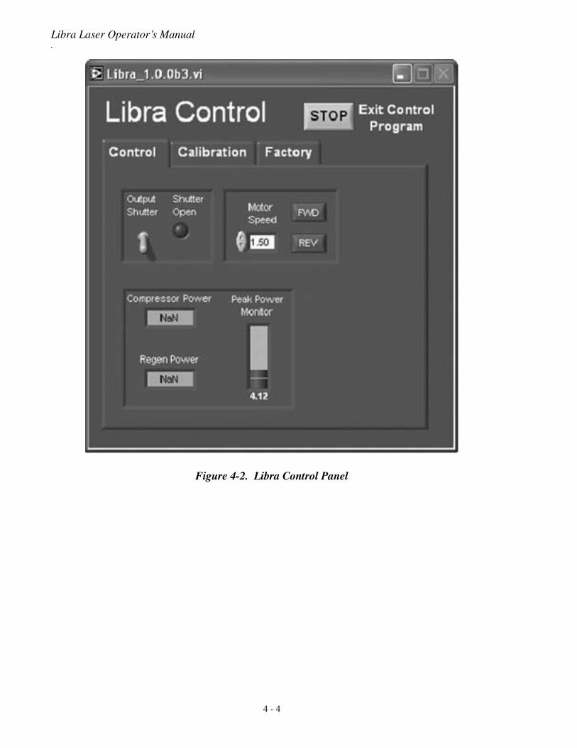
Figure 4-2. Libra Control Panel
4 - 4
Controls and Indicators
Table 4-2. Libra Control Panel
BUTTON OR INDICATOR ACTION OR DESCRIPTION
OUTPUT SHUTTER Toggle the shutter switch to the upright position to open the Libra shutter. The “Shutter Open” LED symbol on the screen will illuminate green.
STOP Click on the gray “STOP” button to save the current settings of the program.
SHUTTER OPEN This indicator turns from gray to green when the Libra "Output Shutter" switch is toggled to the up, open position. The shutter is located between the Regen output and Compressor. When open, light can exit the output port of the Libra.
MOTOR SPEED Input the desired speed of the Compressor stage movement, or use the up/down arrows to increase/decrease the speed.
FWD / REV Push one of these buttons to move the compressor stage in the Forward or Reverse direction. These controls and the feedback from the "Peak Power Monitor" are used to optimize the Libra pulsewidth.
COMPRESSOR POWER This indicator displays the average power after the Compressor. This is the power that is exiting through the output port of the Libra. It is typically 60-75% of the Regen Power.
REGEN POWER This indicator displays the average power after the Regen Cavity. This is the power that is being sent into the compressor.
PEAK POWER MONITOR This relative display is proportional to the Libra pulsewidth. The higher the value, the shorter the pulsewidth. It is typically calibrated such that the shortest pulse is achieved at a value around 9.
CALIBRATION Window This window is used to calibrate the Libra photodiodes. It does not need to be accessed during normal Libra operation.
FACTORY Window This window is used to set and monitor various Libra and communi-cation parameters. It does not need to be accessed during normal Libra operation.
4 - 5
Libra Laser Operator’s Manual
.
Figure 4-3. SDG Control Panel
Table 4-3. SDG Control Panel
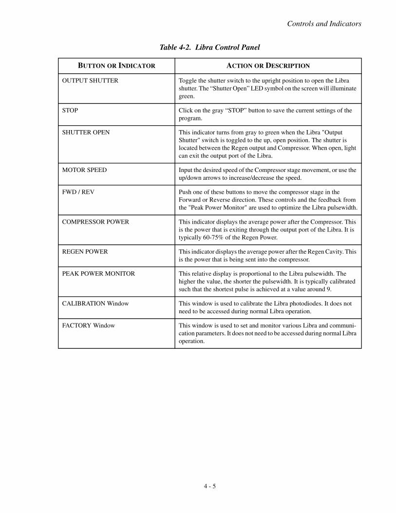
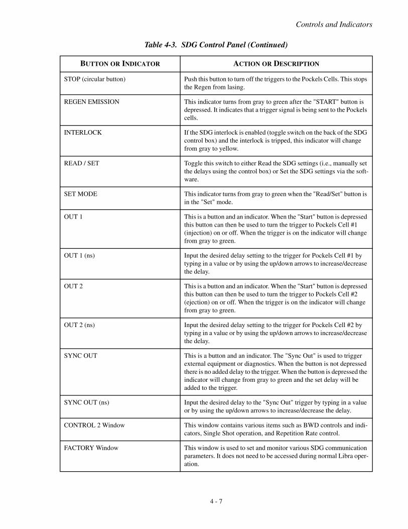
BUTTON OR INDICATOR ACTION OR DESCRIPTION
STOP (rectangular button) Click the gray STOP button on the top right corner of the SDG control screen to exit the program and save the current program settings.
START Push the “START” button to activate the RA. The “Regen Emission” symbol should illuminate.
4 - 6
Controls and Indicators
STOP (circular button) Push this button to turn off the triggers to the Pockels Cells. This stops the Regen from lasing.
REGEN EMISSION This indicator turns from gray to green after the "START" button is depressed. It indicates that a trigger signal is being sent to the Pockels cells.
INTERLOCK If the SDG interlock is enabled (toggle switch on the back of the SDG control box) and the interlock is tripped, this indicator will change from gray to yellow.
READ / SET Toggle this switch to either Read the SDG settings (i.e., manually set the delays using the control box) or Set the SDG settings via the soft-ware.
SET MODE This indicator turns from gray to green when the "Read/Set" button is in the "Set" mode.
OUT 1 This is a button and an indicator. When the "Start" button is depressed this button can then be used to turn the trigger to Pockels Cell #1 (injection) on or off. When the trigger is on the indicator will change from gray to green.
OUT 1 (ns) Input the desired delay setting to the trigger for Pockels Cell #1 by typing in a value or by using the up/down arrows to increase/decrease the delay.
OUT 2 This is a button and an indicator. When the "Start" button is depressed this button can then be used to turn the trigger to Pockels Cell #2 (ejection) on or off. When the trigger is on the indicator will change from gray to green.
OUT 2 (ns) Input the desired delay setting to the trigger for Pockels Cell #2 by typing in a value or by using the up/down arrows to increase/decrease the delay.
SYNC OUT This is a button and an indicator. The "Sync Out" is used to trigger external equipment or diagnostics. When the button is not depressed there is no added delay to the trigger. When the button is depressed the indicator will change from gray to green and the set delay will be added to the trigger.
SYNC OUT (ns) Input the desired delay to the "Sync Out" trigger by typing in a value or by using the up/down arrows to increase/decrease the delay.
CONTROL 2 Window This window contains various items such as BWD controls and indi-cators, Single Shot operation, and Repetition Rate control.
FACTORY Window This window is used to set and monitor various SDG communication parameters. It does not need to be accessed during normal Libra oper-ation.
Table 4-3. SDG Control Panel (Continued)
BUTTON OR INDICATOR ACTION OR DESCRIPTION
4 - 7
Libra Laser Operator’s Manual
.
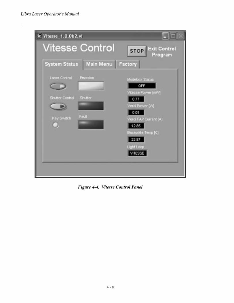
Figure 4-4. Vitesse Control Panel
4 - 8
Controls and Indicators
Table 4-4. Vitesse Control Panel
BUTTON OR INDICATOR ACTION OR DESCRIPTION
STOP Click on the gray STOP button on the Vitesse Control screen to save the current settings of the program.
LASER CONTROL Depress this button to control the current to the Verdi Diodes. When inactive a Verdi FAP current of a couple of Amps will be displayed. When active the preset current will be sent to the diodes.
EMISSION This indicator turns from gray to green after the "START" button is depressed. It indicates that laser light can exit the Vitesse.
SHUTTER CONTROL Depress this button to control the Verdi shutter. When inactive a simmer Verdi FAP current of about 10 Amps will be sent to the diodes. When active the preset current will be sent to the diodes.
SHUTTER This indicator turns from gray to green after the "SHUTTER CONTROL" button is depressed. It indicates that laser light can exit the Vitesse.
KEY SWITCH When the Verdi key located on the Verdi control box is switched from "Standby" to "ON" this indicator will change from gray to green.
FAULT This indicator turns from gray to green if there are any system faults. Toggle the "Evolution Settings" switch and click on the "Fault" tab to view the system fault.
MODELOCK STATUS This indicator displays "OFF" when the system is not modelocked or "MODELOCK" when the system is modelocked. Normal operation requires the system to be in "MODELOCK."
VITESSE POWER This indicator displays the average power exiting the Vitesse.
VERDI POWER This indicator displays the average power exiting the Verdi, the pump laser inside the Vitesse housing.
VERDI FAP CURRENT This indicator displays the Verdi FAP current.
BASPLATE TEMP This indicator displays the temperature of the Verdi baseplate.
LIGHT LOOP This indicator displays the Light Loop status of the Vitesse. There are two modes of operation: Verdi or Vitesse Light Loop. Normal opera-tion is "Vitesse Light Loop."
4 - 9
Libra Laser Operator’s Manual
.
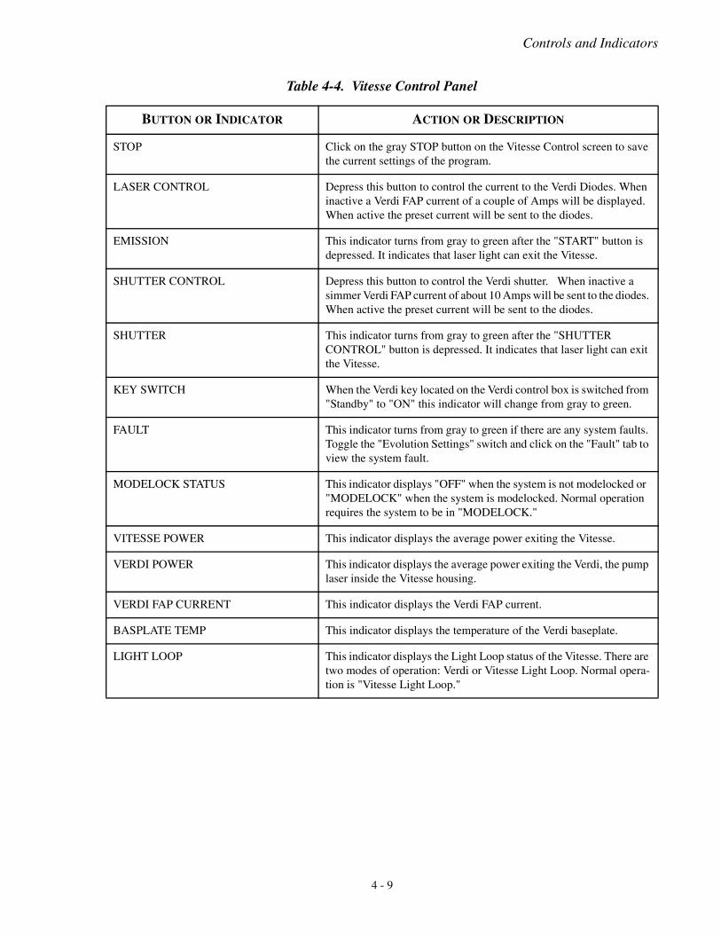
Figure 4-5. Spectrometer Control Panel
Table 4-5. Spectrometer Control Panel
BUTTON OR INDICATOR ACTION OR DESCRIPTION
EXIT Depress the "EXIT" button to save the Spectrometer settings and to exit the Spectrometer program.
SCALE SPECTRUM Depress this button to toggle between a default or scaled (zero to one) amplitude setting.
PEAK Display the wavelength of the peak data point.
SIMPLE FWHM Display the FWHM of the raw (unfitted) spectrum.
CURVE FIT The Spectrometer trace can be fitted when the Spectrum is scaled. Depress this button to display the fit, fitted FWHM, and calculated pulsewidth assuming a transform-limited pulsewidth.
SPECTROMETER SETTINGS Depress this button to toggle between the Spectrometer setting options and the graph display options.
SPECTROMETER ERROR This indicator will change from gray to green when there is a spec-trometer error.
4 - 10
Daily Operation
SECTION FIVE: DAILY OPERATION
All personnel in the area must wear laser safety glasses toprotect against laser radiation. It is assumed that the operatorhas read Section One: Laser Safety and is familiar with properlaser safety practices. Please contact Coherent customer service(800-367-7890) with any questions or potential issues concerninglaser safety.
Laser safety eye wear must be rated to protect against thefollowing wavelengths:
The Libra is normally operated with the laser head and powersupply covers in place. Operation of the laser with the headcover removed allows access to hazardous visible and invisibleradiation. Removal of the power supply cover allows access todangerous voltage and current levels in addition to laser radia-tion. Covers should only be removed for service and mainte-nance by trained personnel aware of the potential hazards.Wearsafety glasses of OD 4 or greater for all lasing wavelengths at alltimes when operating this or any laser system.
Table 5-1. Wavelengths of Radiation Generated by the Libra
LIBRA CONDITION WAVELENGTHS
Covers in place (normal operation) 750 to 850 nm
Optical bench assembly cover removed 525 to 535 nm, 750 to 850 nm
Evolution or Vitesse head cover removed 525 to 535 nm, 750 to 850 nm
Fiber optic cable disconnected 808 nm, 1064 nm
5 - 1
Libra Laser Operator’s Manual
Controls and Diagnostics
The following equipment is recommended to monitor the perfor-mance of the Libra.
• A power meter capable of measuring between 10 mW and10 W average power.
• A fast digital oscilloscope, 300 MHz or better.
• A fast photodiode, for example, the Coherent model LPD.
Software Control
Control Computer The Libra system includes a laptop computer and software to controland monitor the functions of the laser through RS-232 and USBinterfaces. Because of frequent changes in the availability of specificcomputer models, the particular computer delivered with each lasermay vary in brand and features. The control software for the Libra ispre-installed and tested with each laser, and is also supplied on aCD-ROM.
The Libra was built and tested using the computer and controlsoftware that shipped with the laser. Coherent does not endorseor support the use of other computers or software to control theLibra; doing so may void the warranty and/or cause damage tothe laser.
Cold System Startup Procedure
Perform the following steps to initialize the Libra system. At thistime, it is assumed that all power supplies are completely turned off.
Chiller:
1. Turn on the water chiller.
Vitesse:
2. Turn the Vitesse Power Supply on as described in the VitesseOperator’s Manual.
• Allow 30 to 45 minutes for the Vitesse LBO temperatureto stabilize.
5 - 2

Daily Operation
Evolution-15:
3. Enable AC source power to the Evolution power supply bypressing the AC breaker located on the front panel from “0” to“1”. The circuit breaker should illuminate.
4. Turn the power supply key switch from the OFF to the ONposition.
SDG:
5. Turn the SDG AC power on.
Computer:
6. Turn on the laptop computer.
5 - 3
Libra Laser Operator’s Manual
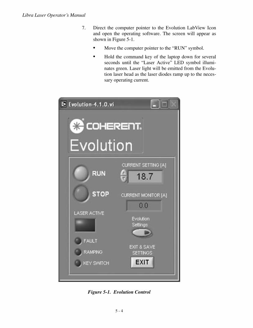
7. Direct the computer pointer to the Evolution LabView Iconand open the operating software. The screen will appear asshown in Figure 5-1.
• Move the computer pointer to the “RUN” symbol.
• Hold the command key of the laptop down for severalseconds until the “Laser Active” LED symbol illumi-nates green. Laser light will be emitted from the Evolu-tion laser head as the laser diodes ramp up to the neces-sary operating current.
Figure 5-1. Evolution Control
5 - 4
Daily Operation
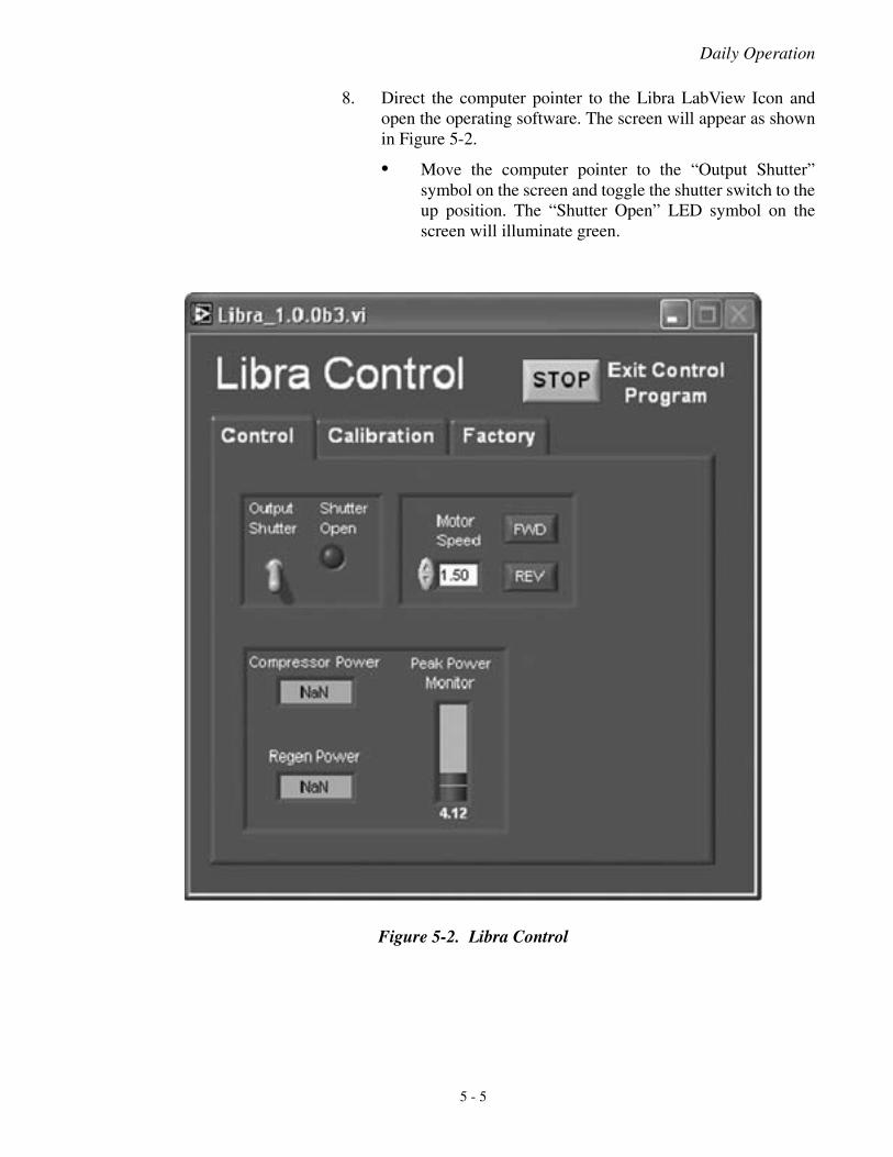
8. Direct the computer pointer to the Libra LabView Icon andopen the operating software. The screen will appear as shownin Figure 5-2.
• Move the computer pointer to the “Output Shutter”symbol on the screen and toggle the shutter switch to theup position. The “Shutter Open” LED symbol on thescreen will illuminate green.
Figure 5-2. Libra Control
5 - 5

Libra Laser Operator’s Manual
9. Direct the computer pointer to the Vitesse LabView Icon andopen the operating software. The screen will appear as shownin Figure 5-3.
• Move the pointer to the “Laser Control” symbol and acti-vate it. The “Emission” LED symbol will illuminate.
Figure 5-3. Vitesse Control
5 - 6
Daily Operation
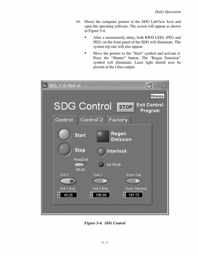
10. Direct the computer pointer to the SDG LabView Icon andopen the operating software. The screen will appear as shownin Figure 5-4.
• After a momentarily delay, both BWD LEDs (PD1 andPD2) on the front panel of the SDG will illuminate. Thesystem rep rate will also appear.
• Move the pointer to the “Start” symbol and activate it.Press the “Shutter” button. The “Regen Emission”symbol will illuminate. Laser light should now bepresent at the Libra output.
Figure 5-4. SDG Control
5 - 7
Libra Laser Operator’s Manual
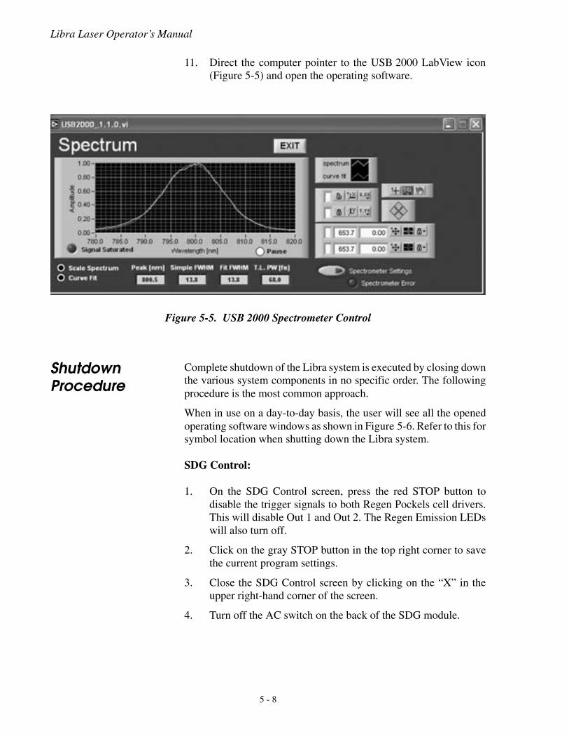
11. Direct the computer pointer to the USB 2000 LabView icon(Figure 5-5) and open the operating software.
Shutdown Procedure
Complete shutdown of the Libra system is executed by closing downthe various system components in no specific order. The followingprocedure is the most common approach.
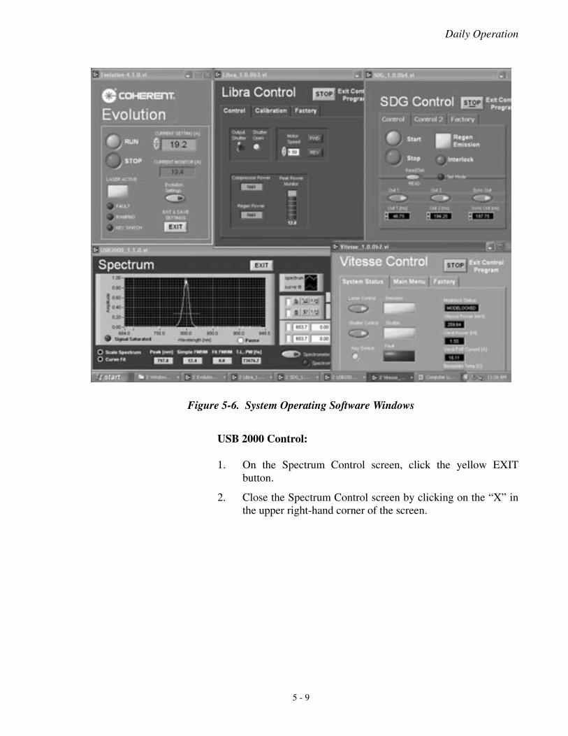
When in use on a day-to-day basis, the user will see all the openedoperating software windows as shown in Figure 5-6. Refer to this forsymbol location when shutting down the Libra system.
SDG Control:
1. On the SDG Control screen, press the red STOP button todisable the trigger signals to both Regen Pockels cell drivers.This will disable Out 1 and Out 2. The Regen Emission LEDswill also turn off.
2. Click on the gray STOP button in the top right corner to savethe current program settings.
3. Close the SDG Control screen by clicking on the “X” in theupper right-hand corner of the screen.
4. Turn off the AC switch on the back of the SDG module.
Figure 5-5. USB 2000 Spectrometer Control
5 - 8
Daily Operation
USB 2000 Control:
1. On the Spectrum Control screen, click the yellow EXITbutton.
2. Close the Spectrum Control screen by clicking on the “X” inthe upper right-hand corner of the screen.
Figure 5-6. System Operating Software Windows
5 - 9
Libra Laser Operator’s Manual
Vitesse Control:
1. On the Vitesse Control screen, click the “Shutter Control”symbol to close the laser intracavity shutter.
2. Click on the gray STOP button to save current programsettings.
3. Close the Vitesse Control screen by clicking on the “X” in theupper right-hand corner of the screen.
4. Manually turn the key on the front panel of the Vitesse powersupply to the STANDBY position.
Libra Control:
1. On the Libra Control screen, toggle the Output Shutter buttondown to close the Shutter. The “Shutter Open” LED on thescreen will turn off when the shutter is closed.
2. Click on the gray “STOP” button to save current programsettings.
3. Close the Libra Control screen by clicking on the “X” in theupper right-hand corner of the screen.
Evolution:
1. On the Evolution Control screen, click the red STOP button toterminate lasing of the Evolution.
2. Click on the yellow EXIT button to save current programsettings.
3. Close the Evolution Control screen by clicking on the “X” inthe upper right-hand corner of the screen.
4. Manually turn the Power Supply keyswitch to the OFF posi-tion.
5. Press the Power Supply switch located on the front panel from1 to 0, disabling AC supply power.
Chiller:
Turn off the water chiller by pushing the on/off button on the frontpanel.
This completes the shutdown procedure for the Libra laser system.
5 - 10
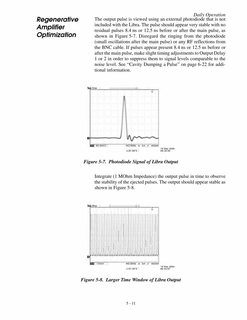
Daily OperationRegenerative Amplifier Optimization
The output pulse is viewed using an external photodiode that is notincluded with the Libra. The pulse should appear very stable with noresidual pulses 8.4 ns or 12.5 ns before or after the main pulse, asshown in Figure 5-7. Disregard the ringing from the photodiode(small oscillations after the main pulse) or any RF reflections fromthe BNC cable. If pulses appear present 8.4 ns or 12.5 ns before orafter the main pulse, make slight timing adjustments to Output Delay1 or 2 in order to suppress them to signal levels comparable to thenoise level. See “Cavity Dumping a Pulse” on page 6-22 for addi-tional information.
Integrate (1 MOhm Impedance) the output pulse in time to observethe stability of the ejected pulses. The output should appear stable asshown in Figure 5-8.
Figure 5-7. Photodiode Signal of Libra Output
Figure 5-8. Larger Time Window of Libra Output
5 - 11
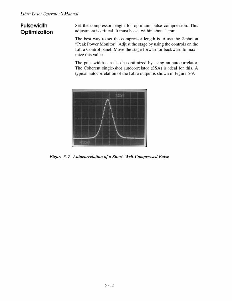
Libra Laser Operator’s Manual
Pulsewidth Optimization
Set the compressor length for optimum pulse compression. Thisadjustment is critical. It must be set within about 1 mm.
The best way to set the compressor length is to use the 2-photon“Peak Power Monitor.” Adjust the stage by using the controls on theLibra Control panel. Move the stage forward or backward to maxi-mize this value.
The pulsewidth can also be optimized by using an autocorrelator.The Coherent single-shot autocorrelator (SSA) is ideal for this. Atypical autocorrelation of the Libra output is shown in Figure 5-9.
Figure 5-9. Autocorrelation of a Short, Well-Compressed Pulse
5 - 12
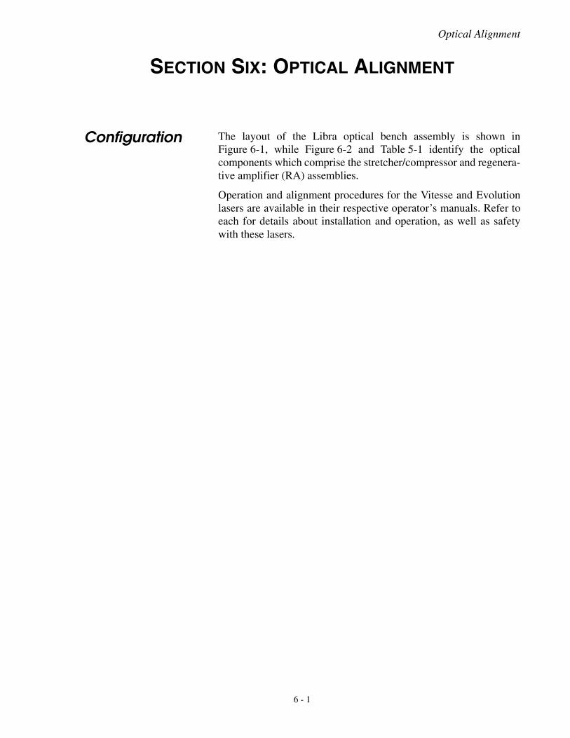
Optical Alignment
SECTION SIX: OPTICAL ALIGNMENT
Configuration The layout of the Libra optical bench assembly is shown inFigure 6-1, while Figure 6-2 and Table 5-1 identify the opticalcomponents which comprise the stretcher/compressor and regenera-tive amplifier (RA) assemblies.
Operation and alignment procedures for the Vitesse and Evolutionlasers are available in their respective operator’s manuals. Refer toeach for details about installation and operation, as well as safetywith these lasers.
6 - 1
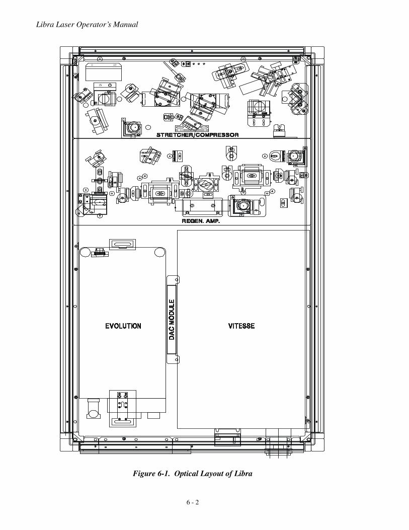
Libra Laser Operator’s Manual
Figure 6-1. Optical Layout of Libra
6 - 2
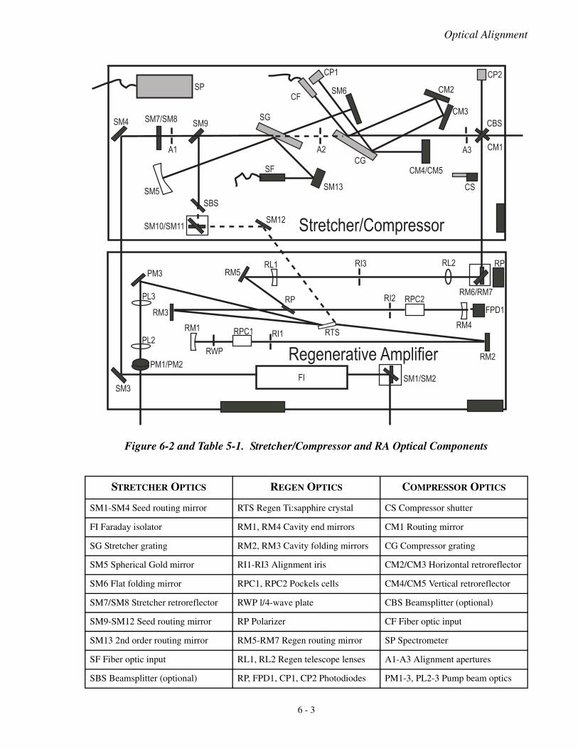
Optical Alignment
Figure 6-2 and Table 5-1. Stretcher/Compressor and RA Optical Components
STRETCHER OPTICS REGEN OPTICS COMPRESSOR OPTICS
SM1-SM4 Seed routing mirror RTS Regen Ti:sapphire crystal CS Compressor shutter
FI Faraday isolator RM1, RM4 Cavity end mirrors CM1 Routing mirror
SG Stretcher grating RM2, RM3 Cavity folding mirrors CG Compressor grating
SM5 Spherical Gold mirror RI1-RI3 Alignment iris CM2/CM3 Horizontal retroreflector
SM6 Flat folding mirror RPC1, RPC2 Pockels cells CM4/CM5 Vertical retroreflector
SM7/SM8 Stretcher retroreflector RWP l/4-wave plate CBS Beamsplitter (optional)
SM9-SM12 Seed routing mirror RP Polarizer CF Fiber optic input
SM13 2nd order routing mirror RM5-RM7 Regen routing mirror SP Spectrometer
SF Fiber optic input RL1, RL2 Regen telescope lenses A1-A3 Alignment apertures
SBS Beamsplitter (optional) RP, FPD1, CP1, CP2 Photodiodes PM1-3, PL2-3 Pump beam optics
��
��� ������� ��
��
������������
��
��
��� ��
���
��
����
� ��
������
��
������
���
��
���
������
��
���
���
���
���
����
��
��� ���
��
��� ���
�� ���
���
��
�������
��
����
��
������
�������� !"�#�$%&!'!��
� �� ()����*$%��++*�
�����
���
����
6 - 3
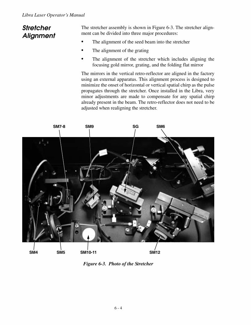
Libra Laser Operator’s Manual
Stretcher Alignment
The stretcher assembly is shown in Figure 6-3. The stretcher align-ment can be divided into three major procedures:
• The alignment of the seed beam into the stretcher
• The alignment of the grating
• The alignment of the stretcher which includes aligning thefocusing gold mirror, grating, and the folding flat mirror
The mirrors in the vertical retro-reflector are aligned in the factoryusing an external apparatus. This alignment process is designed tominimize the onset of horizontal or vertical spatial chirp as the pulsepropagates through the stretcher. Once installed in the Libra, veryminor adjustments are made to compensate for any spatial chirpalready present in the beam. The retro-reflector does not need to beadjusted when realigning the stretcher.
Figure 6-3. Photo of the Stretcher
SM7-8 SM9 SG SM6
SM4 SM5 SM10-11 SM12
6 - 4
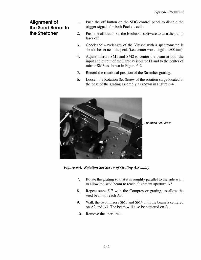
Optical Alignment
Alignment of the Seed Beam to the Stretcher
1. Push the off button on the SDG control panel to disable thetrigger signals for both Pockels cells.
2. Push the off button on the Evolution software to turn the pumplaser off.
3. Check the wavelength of the Vitesse with a spectrometer. Itshould be set near the peak (i.e., center wavelength ~ 800 nm).
4. Adjust mirrors SM1 and SM2 to center the beam at both theinput and output of the Faraday isolator FI and to the center ofmirror SM3 as shown in Figure 6-2.
5. Record the rotational position of the Stretcher grating.
6. Loosen the Rotation Set Screw of the rotation stage located atthe base of the grating assembly as shown in Figure 6-4.
7. Rotate the grating so that it is roughly parallel to the side wall,to allow the seed beam to reach alignment aperture A2.
8. Repeat steps 5-7 with the Compressor grating, to allow theseed beam to reach A3.
9. Walk the two mirrors SM3 and SM4 until the beam is centeredon A2 and A3. The beam will also be centered on A1.
10. Remove the apertures.
Figure 6-4. Rotation Set Screw of Grating Assembly
Rotation Set Screw
6 - 5
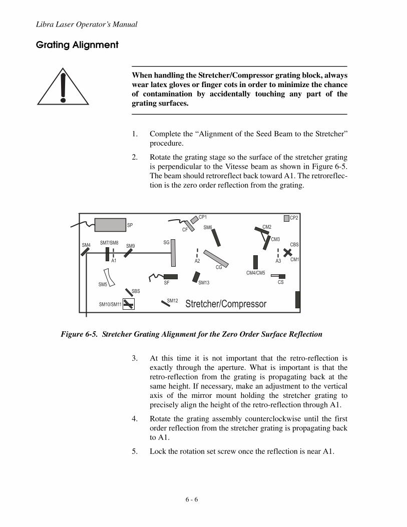
Libra Laser Operator’s Manual
Grating Alignment
When handling the Stretcher/Compressor grating block, alwayswear latex gloves or finger cots in order to minimize the chanceof contamination by accidentally touching any part of thegrating surfaces.
1. Complete the “Alignment of the Seed Beam to the Stretcher”procedure.
2. Rotate the grating stage so the surface of the stretcher gratingis perpendicular to the Vitesse beam as shown in Figure 6-5.The beam should retroreflect back toward A1. The retroreflec-tion is the zero order reflection from the grating.
3. At this time it is not important that the retro-reflection isexactly through the aperture. What is important is that theretro-reflection from the grating is propagating back at thesame height. If necessary, make an adjustment to the verticalaxis of the mirror mount holding the stretcher grating toprecisely align the height of the retro-reflection through A1.
4. Rotate the grating assembly counterclockwise until the firstorder reflection from the stretcher grating is propagating backto A1.
5. Lock the rotation set screw once the reflection is near A1.
Figure 6-5. Stretcher Grating Alignment for the Zero Order Surface Reflection
��
��� ���������
��
������������
��
���
�� ����
���
���
��
� �� ()����*$%��++*�
��
��� ��
� ��
������
��
���
��
���
��
6 - 6
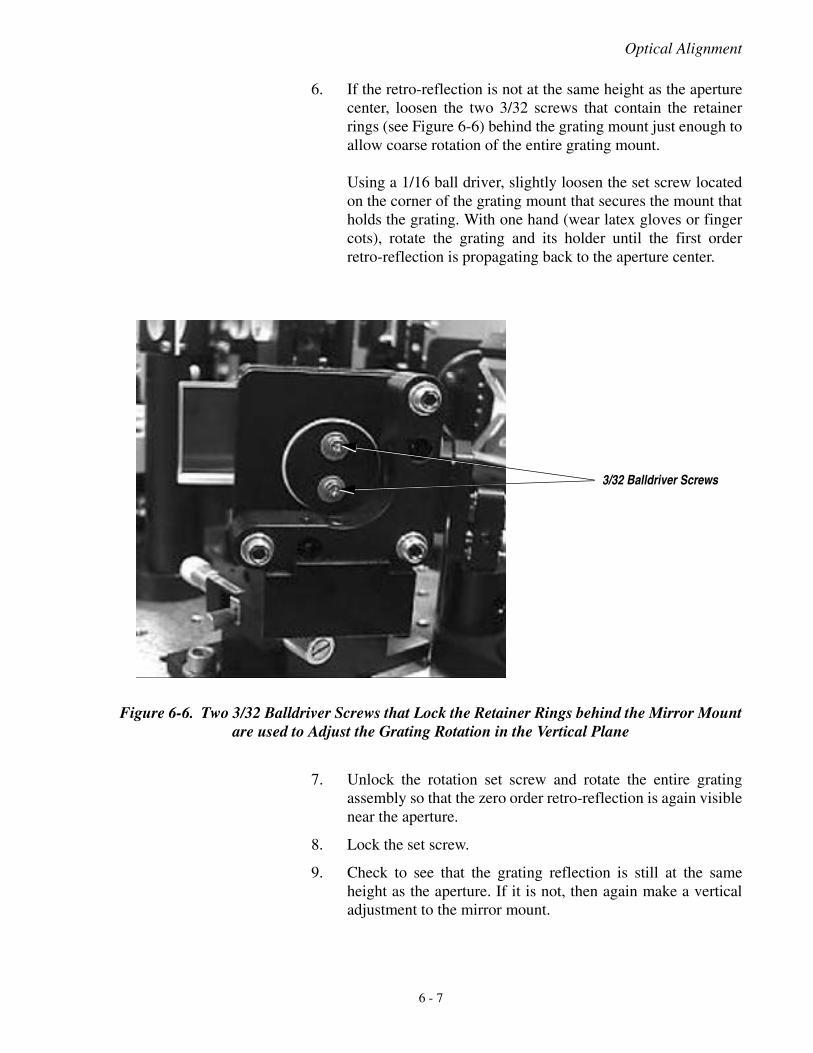
Optical Alignment
6. If the retro-reflection is not at the same height as the aperturecenter, loosen the two 3/32 screws that contain the retainerrings (see Figure 6-6) behind the grating mount just enough toallow coarse rotation of the entire grating mount.
Using a 1/16 ball driver, slightly loosen the set screw locatedon the corner of the grating mount that secures the mount thatholds the grating. With one hand (wear latex gloves or fingercots), rotate the grating and its holder until the first orderretro-reflection is propagating back to the aperture center.
7. Unlock the rotation set screw and rotate the entire gratingassembly so that the zero order retro-reflection is again visiblenear the aperture.
8. Lock the set screw.
9. Check to see that the grating reflection is still at the sameheight as the aperture. If it is not, then again make a verticaladjustment to the mirror mount.
Figure 6-6. Two 3/32 Balldriver Screws that Lock the Retainer Rings behind the Mirror Mountare used to Adjust the Grating Rotation in the Vertical Plane
3/32 Balldriver Screws
6 - 7
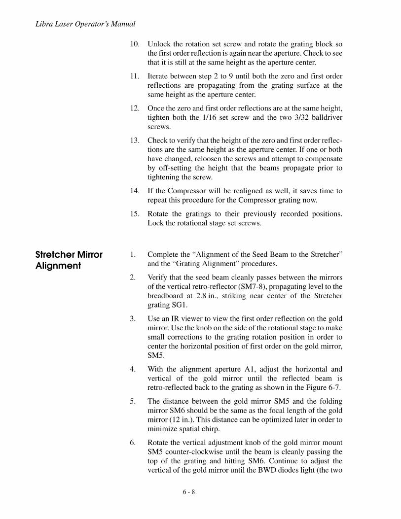
Libra Laser Operator’s Manual
10. Unlock the rotation set screw and rotate the grating block sothe first order reflection is again near the aperture. Check to seethat it is still at the same height as the aperture center.
11. Iterate between step 2 to 9 until both the zero and first orderreflections are propagating from the grating surface at thesame height as the aperture center.
12. Once the zero and first order reflections are at the same height,tighten both the 1/16 set screw and the two 3/32 balldriverscrews.
13. Check to verify that the height of the zero and first order reflec-tions are the same height as the aperture center. If one or bothhave changed, reloosen the screws and attempt to compensateby off-setting the height that the beams propagate prior totightening the screw.
14. If the Compressor will be realigned as well, it saves time torepeat this procedure for the Compressor grating now.
15. Rotate the gratings to their previously recorded positions.Lock the rotational stage set screws.
Stretcher Mirror Alignment
1. Complete the “Alignment of the Seed Beam to the Stretcher”and the “Grating Alignment” procedures.
2. Verify that the seed beam cleanly passes between the mirrorsof the vertical retro-reflector (SM7-8), propagating level to thebreadboard at 2.8 in., striking near center of the Stretchergrating SG1.
3. Use an IR viewer to view the first order reflection on the goldmirror. Use the knob on the side of the rotational stage to makesmall corrections to the grating rotation position in order tocenter the horizontal position of first order on the gold mirror,SM5.
4. With the alignment aperture A1, adjust the horizontal andvertical of the gold mirror until the reflected beam isretro-reflected back to the grating as shown in the Figure 6-7.
5. The distance between the gold mirror SM5 and the foldingmirror SM6 should be the same as the focal length of the goldmirror (12 in.). This distance can be optimized later in order tominimize spatial chirp.
6. Rotate the vertical adjustment knob of the gold mirror mountSM5 counter-clockwise until the beam is cleanly passing thetop of the grating and hitting SM6. Continue to adjust thevertical of the gold mirror until the BWD diodes light (the two
6 - 8
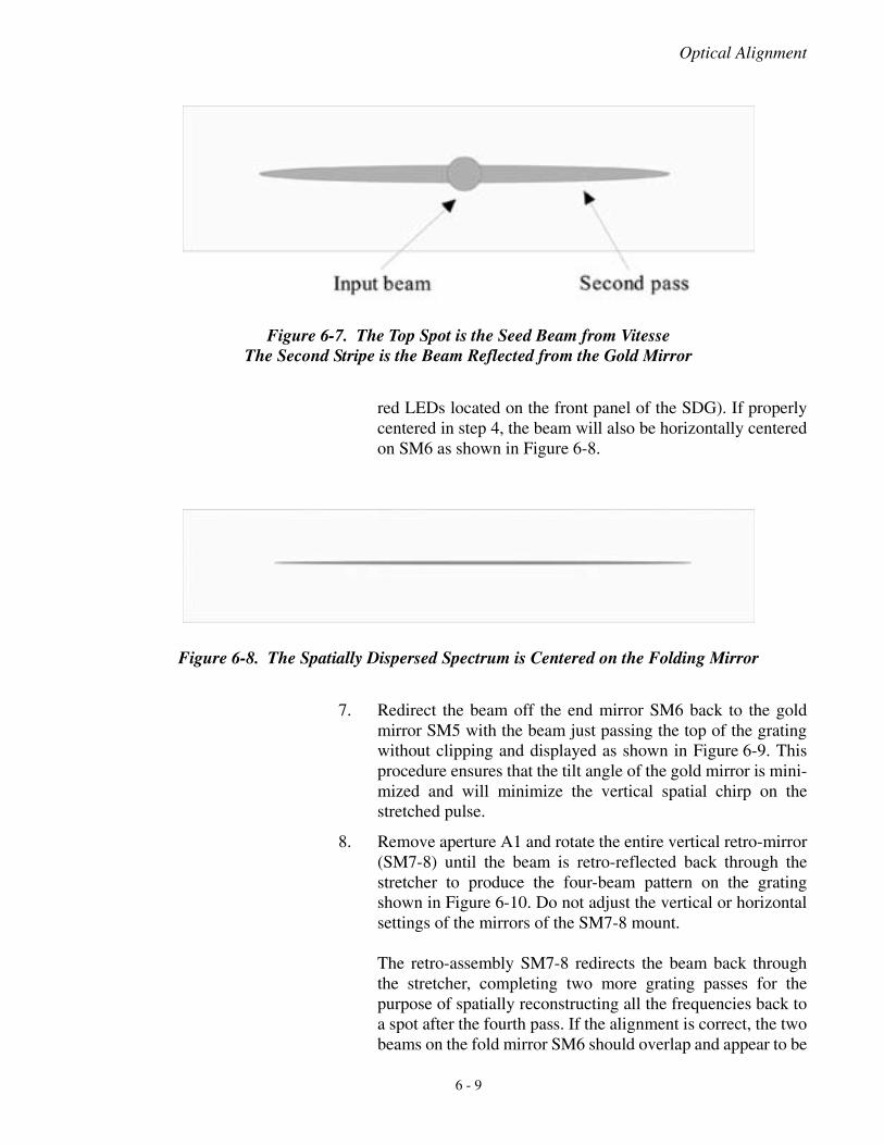
Optical Alignment
red LEDs located on the front panel of the SDG). If properlycentered in step 4, the beam will also be horizontally centeredon SM6 as shown in Figure 6-8.
7. Redirect the beam off the end mirror SM6 back to the goldmirror SM5 with the beam just passing the top of the gratingwithout clipping and displayed as shown in Figure 6-9. Thisprocedure ensures that the tilt angle of the gold mirror is mini-mized and will minimize the vertical spatial chirp on thestretched pulse.
8. Remove aperture A1 and rotate the entire vertical retro-mirror(SM7-8) until the beam is retro-reflected back through thestretcher to produce the four-beam pattern on the gratingshown in Figure 6-10. Do not adjust the vertical or horizontalsettings of the mirrors of the SM7-8 mount.
The retro-assembly SM7-8 redirects the beam back throughthe stretcher, completing two more grating passes for thepurpose of spatially reconstructing all the frequencies back toa spot after the fourth pass. If the alignment is correct, the twobeams on the fold mirror SM6 should overlap and appear to be
Figure 6-7. The Top Spot is the Seed Beam from VitesseThe Second Stripe is the Beam Reflected from the Gold Mirror
Figure 6-8. The Spatially Dispersed Spectrum is Centered on the Folding Mirror
6 - 9
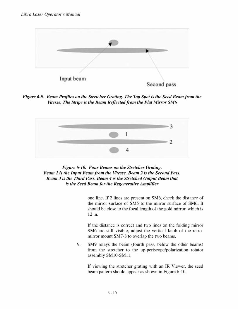
Libra Laser Operator’s Manual
one line. If 2 lines are present on SM6, check the distance ofthe mirror surface of SM5 to the mirror surface of SM6. Itshould be close to the focal length of the gold mirror, which is12 in.
If the distance is correct and two lines on the folding mirrorSM6 are still visible, adjust the vertical knob of the retro-mirror mount SM7-8 to overlap the two beams.
9. SM9 relays the beam (fourth pass, below the other beams)from the stretcher to the up-periscope/polarization rotatorassembly SM10-SM11.
If viewing the stretcher grating with an IR Viewer, the seedbeam pattern should appear as shown in Figure 6-10.
Figure 6-9. Beam Profiles on the Stretcher Grating. The Top Spot is the Seed Beam from the Vitesse. The Stripe is the Beam Reflected from the Flat Mirror SM6
Figure 6-10. Four Beams on the Stretcher Grating.Beam 1 is the Input Beam from the Vitesse. Beam 2 is the Second Pass.
Beam 3 is the Third Pass. Beam 4 is the Stretched Output Beam thatis the Seed Beam for the Regenerative Amplifier
6 - 10
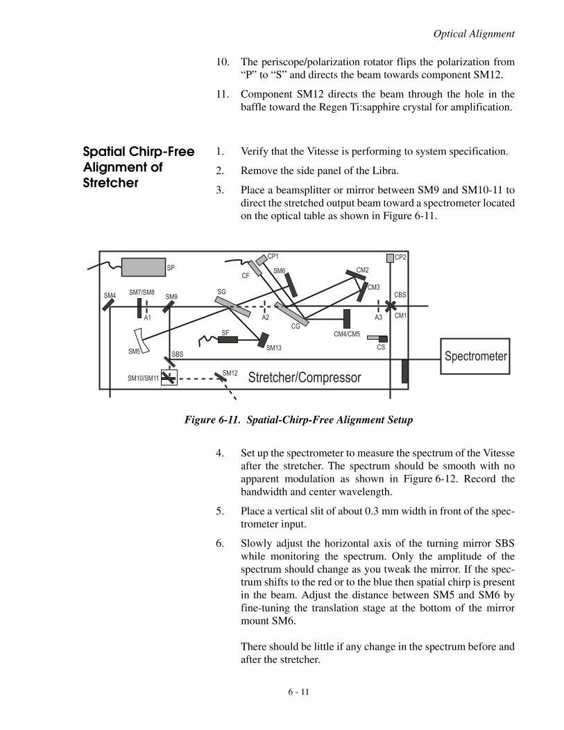
Optical Alignment
10. The periscope/polarization rotator flips the polarization from“P” to “S” and directs the beam towards component SM12.
11. Component SM12 directs the beam through the hole in thebaffle toward the Regen Ti:sapphire crystal for amplification.
Spatial Chirp-Free Alignment of Stretcher
1. Verify that the Vitesse is performing to system specification.
2. Remove the side panel of the Libra.
3. Place a beamsplitter or mirror between SM9 and SM10-11 todirect the stretched output beam toward a spectrometer locatedon the optical table as shown in Figure 6-11.
4. Set up the spectrometer to measure the spectrum of the Vitesseafter the stretcher. The spectrum should be smooth with noapparent modulation as shown in Figure 6-12. Record thebandwidth and center wavelength.
5. Place a vertical slit of about 0.3 mm width in front of the spec-trometer input.
6. Slowly adjust the horizontal axis of the turning mirror SBSwhile monitoring the spectrum. Only the amplitude of thespectrum should change as you tweak the mirror. If the spec-trum shifts to the red or to the blue then spatial chirp is presentin the beam. Adjust the distance between SM5 and SM6 byfine-tuning the translation stage at the bottom of the mirrormount SM6.
There should be little if any change in the spectrum before andafter the stretcher.
Figure 6-11. Spatial-Chirp-Free Alignment Setup
��
��� ���������
��
������������
��
��
��� ��
���
��
����
� ��
������
��
������
���
���%�( �*$� ��
� �� ()����*$%��++*�
��
���
��
6 - 11
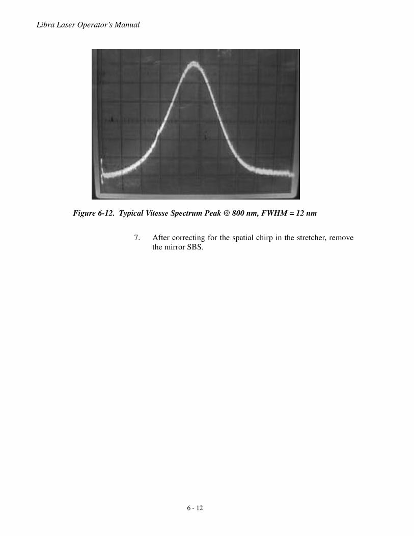
Libra Laser Operator’s Manual
7. After correcting for the spatial chirp in the stretcher, removethe mirror SBS.
Figure 6-12. Typical Vitesse Spectrum Peak @ 800 nm, FWHM = 12 nm
6 - 12
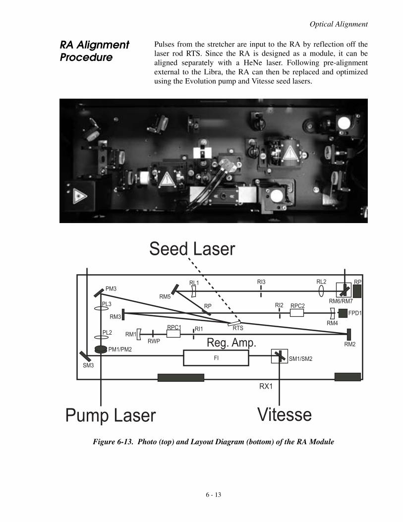
Optical Alignment
RA Alignment Procedure
Pulses from the stretcher are input to the RA by reflection off thelaser rod RTS. Since the RA is designed as a module, it can bealigned separately with a HeNe laser. Following pre-alignmentexternal to the Libra, the RA can then be replaced and optimizedusing the Evolution pump and Vitesse seed lasers.
Figure 6-13. Photo (top) and Layout Diagram (bottom) of the RA Module
���
������
��
���
���
������
����
��
��� ���
��
��� ���
�� ���
���
��
�������
��
����
��
������
���,#�$%,
�����
���-#��+��
.! �++��/$%#��+��
�0�
6 - 13
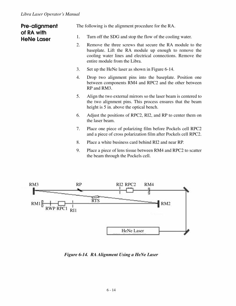
Libra Laser Operator’s Manual
Pre-alignment of RA with HeNe Laser
The following is the alignment procedure for the RA.
1. Turn off the SDG and stop the flow of the cooling water.
2. Remove the three screws that secure the RA module to thebaseplate. Lift the RA module up enough to remove thecooling water lines and electrical connections. Remove theentire module from the Libra.
3. Set up the HeNe laser as shown in Figure 6-14.
4. Drop two alignment pins into the baseplate. Position onebetween components RM4 and RPC2 and the other betweenRP and RM3.
5. Align the two external mirrors so the laser beam is centered tothe two alignment pins. This process ensures that the beamheight is 5 in. above the optical bench.
6. Adjust the positions of RPC2, RI2, and RP to center them onthe laser beam.
7. Place one piece of polarizing film before Pockels cell RPC2and a piece of cross polarization film after Pockels cell RPC2.
8. Place a white business card behind RI2 and near RP.
9. Place a piece of lens tissue between RM4 and RPC2 to scatterthe beam through the Pockels cell.
Figure 6-14. RA Alignment Using a HeNe Laser
RM2RM1
RM4RI2RPRM3
RWP RPC1 RI1
RTS
HeNe Laser
RPC2
6 - 14
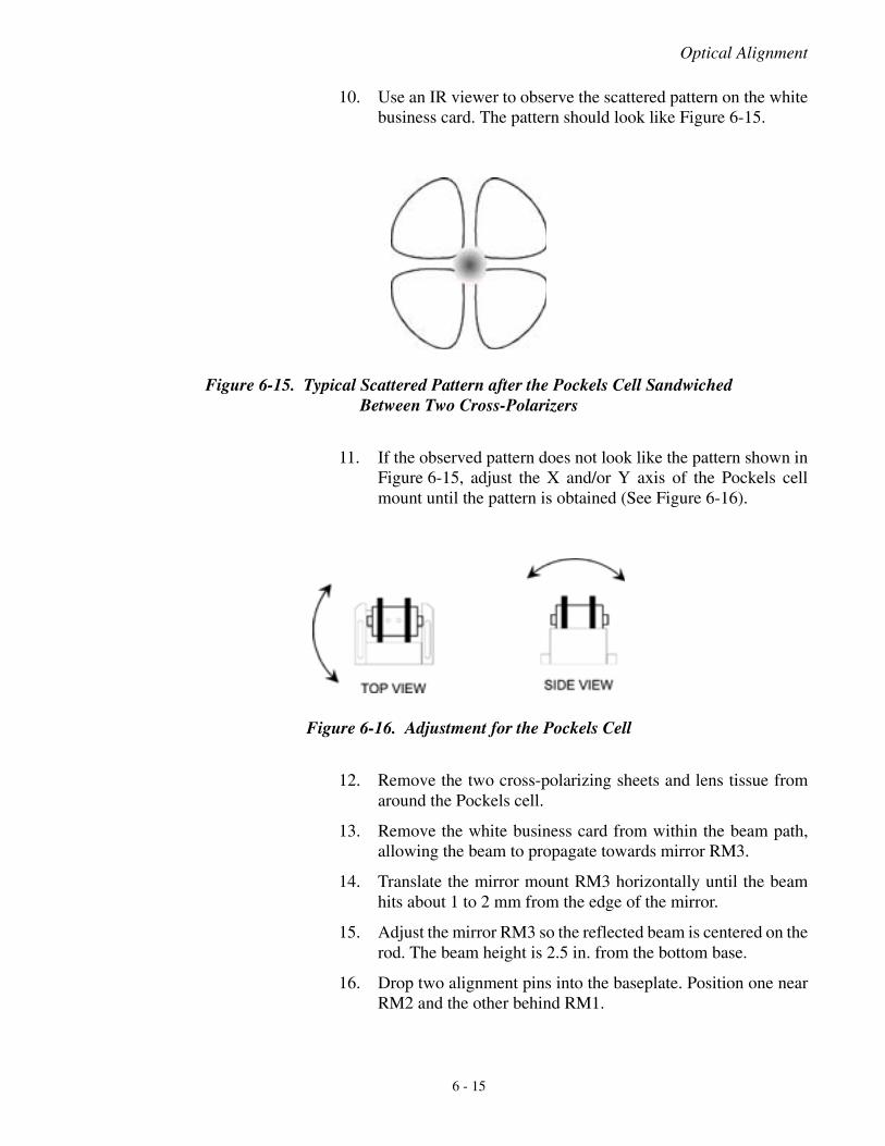
Optical Alignment
10. Use an IR viewer to observe the scattered pattern on the whitebusiness card. The pattern should look like Figure 6-15.
11. If the observed pattern does not look like the pattern shown inFigure 6-15, adjust the X and/or Y axis of the Pockels cellmount until the pattern is obtained (See Figure 6-16).
12. Remove the two cross-polarizing sheets and lens tissue fromaround the Pockels cell.
13. Remove the white business card from within the beam path,allowing the beam to propagate towards mirror RM3.
14. Translate the mirror mount RM3 horizontally until the beamhits about 1 to 2 mm from the edge of the mirror.
15. Adjust the mirror RM3 so the reflected beam is centered on therod. The beam height is 2.5 in. from the bottom base.
16. Drop two alignment pins into the baseplate. Position one nearRM2 and the other behind RM1.
Figure 6-15. Typical Scattered Pattern after the Pockels Cell SandwichedBetween Two Cross-Polarizers
Figure 6-16. Adjustment for the Pockels Cell
6 - 15

Libra Laser Operator’s Manual
17. Align the beam with mirrors RM3 and RM2 to center it on bothalignment pins.
18. Adjust the positions of RPC1, RI1, and RW to center them inthe laser beam.
19. Repeat steps 7 through 13 to adjust Pockels cell RPC1.
20. Close the two irises to less than 1 mm in diameter.
21. Align the mirror RM1 so the reflected beam is centered onboth RI1 and RI2.
22. Align mirror RM4 so the beam is reflected back to the centerof the output of the HeNe laser.
23. Open the two irises.
This concludes the pre-alignment procedures for the regenerative.amplifier.
Final Alignment of RA with Seed Beam
The following is the alignment of the RA with the seed beam.
1. Place the RA module into the Libra as shown in Figure 6-1,making sure to connect the water and electrical lines. Securethe module with the three screws.
2. Adjust mirrors SM9 and SM11 until the seed beam is paralleland 5 in. above the optical table.
3. If necessary, re-position SM12 until the seed beam is hittingnear the center of the optic.
4. Adjust the mirror SM12 so the reflected beam is also 5 in.above the optical bench.
5. Adjust the horizontal of mirror SM12 until the seed beam iscentered on the rod. The beam reflected off the rod should be2.5 in. above the RA bench.
6. Make small adjustments to mirrors SM11 and SM12 until thebeam is centered through RI2 and RI1.
7. Make small adjustments to the end mirror RM1 to retrace thebeam back through RI1 and RI2.
The RA should now lase when pumped by the Evolution without anyadjustments to the RA cavity.
6 - 16
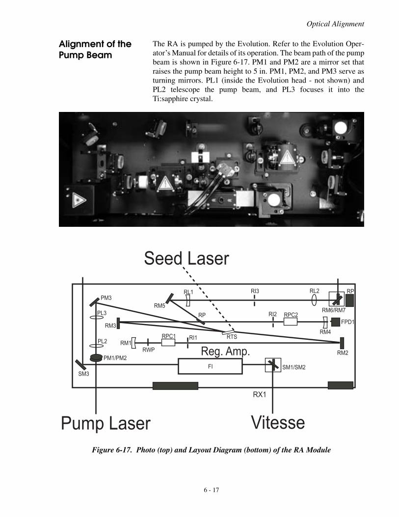
Optical Alignment
Alignment of the Pump Beam
The RA is pumped by the Evolution. Refer to the Evolution Oper-ator’s Manual for details of its operation. The beam path of the pumpbeam is shown in Figure 6-17. PM1 and PM2 are a mirror set thatraises the pump beam height to 5 in. PM1, PM2, and PM3 serve asturning mirrors. PL1 (inside the Evolution head - not shown) andPL2 telescope the pump beam, and PL3 focuses it into theTi:sapphire crystal.
Figure 6-17. Photo (top) and Layout Diagram (bottom) of the RA Module
���
������
��
���
���
������
����
��
��� ���
��
��� ���
�� ���
���
��
�������
��
����
��
������
���,#�$%,
�����
���-#��+��
.! �++��/$%#��+��
�0�
6 - 17
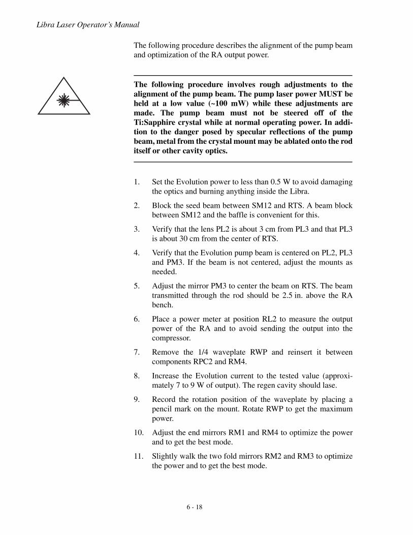
Libra Laser Operator’s Manual
The following procedure describes the alignment of the pump beamand optimization of the RA output power.
The following procedure involves rough adjustments to thealignment of the pump beam. The pump laser power MUST beheld at a low value (~100 mW) while these adjustments aremade. The pump beam must not be steered off of theTi:Sapphire crystal while at normal operating power. In addi-tion to the danger posed by specular reflections of the pumpbeam, metal from the crystal mount may be ablated onto the roditself or other cavity optics.
1. Set the Evolution power to less than 0.5 W to avoid damagingthe optics and burning anything inside the Libra.
2. Block the seed beam between SM12 and RTS. A beam blockbetween SM12 and the baffle is convenient for this.
3. Verify that the lens PL2 is about 3 cm from PL3 and that PL3is about 30 cm from the center of RTS.
4. Verify that the Evolution pump beam is centered on PL2, PL3and PM3. If the beam is not centered, adjust the mounts asneeded.
5. Adjust the mirror PM3 to center the beam on RTS. The beamtransmitted through the rod should be 2.5 in. above the RAbench.
6. Place a power meter at position RL2 to measure the outputpower of the RA and to avoid sending the output into thecompressor.
7. Remove the 1/4 waveplate RWP and reinsert it betweencomponents RPC2 and RM4.
8. Increase the Evolution current to the tested value (approxi-mately 7 to 9 W of output). The regen cavity should lase.
9. Record the rotation position of the waveplate by placing apencil mark on the mount. Rotate RWP to get the maximumpower.
10. Adjust the end mirrors RM1 and RM4 to optimize the powerand to get the best mode.
11. Slightly walk the two fold mirrors RM2 and RM3 to optimizethe power and to get the best mode.
6 - 18
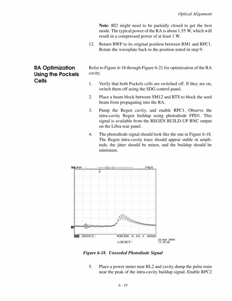
Optical Alignment
Note: RI2 might need to be partially closed to get the bestmode. The typical power of the RA is about 1.55 W, which willresult in a compressed power of at least 1 W.
12. Return RWP to its original position between RM1 and RPC1.Rotate the waveplate back to the position noted in step 9.
RA Optimization Using the Pockels Cells
Refer to Figure 6-18 through Figure 6-21 for optimization of the RAcavity.
1. Verify that both Pockels cells are switched off. If they are on,switch them off using the SDG control panel.
2. Place a beam block between SM12 and RTS to block the seedbeam from propagating into the RA.
3. Pump the Regen cavity, and enable RPC1. Observe theintra-cavity Regen buildup using photodiode FPD1. Thissignal is available from the REGEN BUILD-UP BNC outputon the Libra rear panel.
4. The photodiode signal should look like the one in Figure 6-18.The Regen intra-cavity trace should appear stable in ampli-tude, the jitter should be minor, and the buildup should beminimum.
5. Place a power meter near RL2 and cavity dump the pulse trainnear the peak of the intra-cavity buildup signal. Enable RPC2
Figure 6-18. Unseeded Photodiode Signal
6 - 19
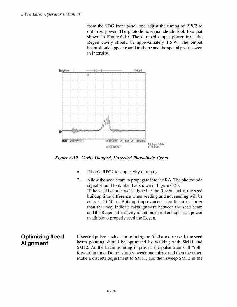
Libra Laser Operator’s Manual
from the SDG front panel, and adjust the timing of RPC2 tooptimize power. The photodiode signal should look like thatshown in Figure 6-19. The dumped output power from theRegen cavity should be approximately 1.5 W. The outputbeam should appear round in shape and the spatial profile evenin intensity.
6. Disable RPC2 to stop cavity dumping.
7. Allow the seed beam to propagate into the RA. The photodiodesignal should look like that shown in Figure 6-20.If the seed beam is well-aligned to the Regen cavity, the seedbuildup time difference when seeding and not seeding will beat least 45-50 ns. Buildup improvement significantly shorterthan that may indicate misalignment between the seed beamand the Regen intra-cavity radiation, or not enough seed poweravailable to properly seed the Regen.
Optimizing Seed Alignment
If seeded pulses such as those in Figure 6-20 are observed, the seedbeam pointing should be optimized by walking with SM11 andSM12. As the beam pointing improves, the pulse train will “roll”forward in time. Do not simply tweak one mirror and then the other.Make a discrete adjustment to SM11, and then sweep SM12 in the
Figure 6-19. Cavity Dumped, Unseeded Photodiode Signal
6 - 20
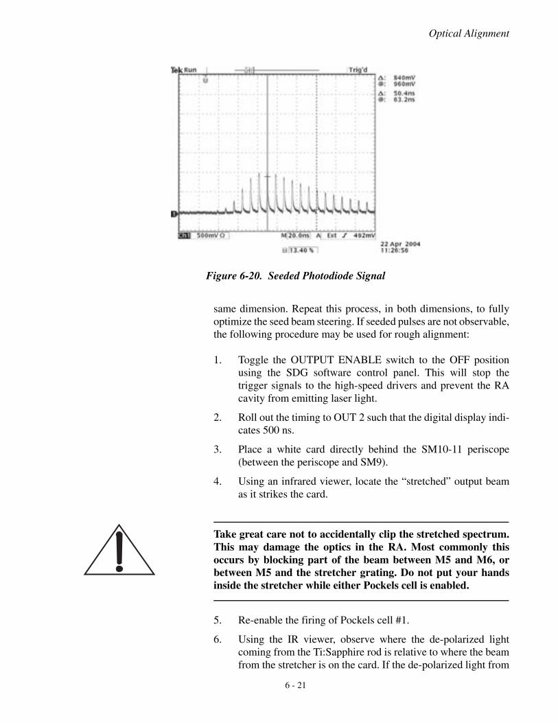
Optical Alignment
same dimension. Repeat this process, in both dimensions, to fullyoptimize the seed beam steering. If seeded pulses are not observable,the following procedure may be used for rough alignment:
1. Toggle the OUTPUT ENABLE switch to the OFF positionusing the SDG software control panel. This will stop thetrigger signals to the high-speed drivers and prevent the RAcavity from emitting laser light.
2. Roll out the timing to OUT 2 such that the digital display indi-cates 500 ns.
3. Place a white card directly behind the SM10-11 periscope(between the periscope and SM9).
4. Using an infrared viewer, locate the “stretched” output beamas it strikes the card.
Take great care not to accidentally clip the stretched spectrum.This may damage the optics in the RA. Most commonly thisoccurs by blocking part of the beam between M5 and M6, orbetween M5 and the stretcher grating. Do not put your handsinside the stretcher while either Pockels cell is enabled.
5. Re-enable the firing of Pockels cell #1.
6. Using the IR viewer, observe where the de-polarized lightcoming from the Ti:Sapphire rod is relative to where the beamfrom the stretcher is on the card. If the de-polarized light from
Figure 6-20. Seeded Photodiode Signal
6 - 21
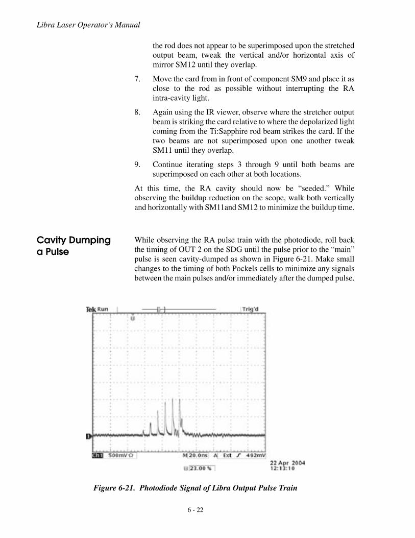
Libra Laser Operator’s Manual
the rod does not appear to be superimposed upon the stretchedoutput beam, tweak the vertical and/or horizontal axis ofmirror SM12 until they overlap.
7. Move the card from in front of component SM9 and place it asclose to the rod as possible without interrupting the RAintra-cavity light.
8. Again using the IR viewer, observe where the stretcher outputbeam is striking the card relative to where the depolarized lightcoming from the Ti:Sapphire rod beam strikes the card. If thetwo beams are not superimposed upon one another tweakSM11 until they overlap.
9. Continue iterating steps 3 through 9 until both beams aresuperimposed on each other at both locations.
At this time, the RA cavity should now be “seeded.” Whileobserving the buildup reduction on the scope, walk both verticallyand horizontally with SM11and SM12 to minimize the buildup time.
Cavity Dumping a Pulse
While observing the RA pulse train with the photodiode, roll backthe timing of OUT 2 on the SDG until the pulse prior to the “main”pulse is seen cavity-dumped as shown in Figure 6-21. Make smallchanges to the timing of both Pockels cells to minimize any signalsbetween the main pulses and/or immediately after the dumped pulse.
Figure 6-21. Photodiode Signal of Libra Output Pulse Train
6 - 22
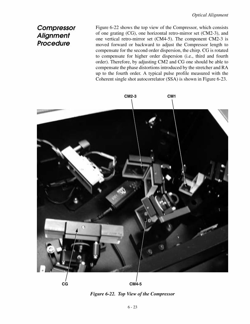
Optical Alignment
Compressor Alignment Procedure
Figure 6-22 shows the top view of the Compressor, which consistsof one grating (CG), one horizontal retro-mirror set (CM2-3), andone vertical retro-mirror set (CM4-5). The component CM2-3 ismoved forward or backward to adjust the Compressor length tocompensate for the second order dispersion, the chirp. CG is rotatedto compensate for higher order dispersion (i.e., third and fourthorder). Therefore, by adjusting CM2 and CG one should be able tocompensate the phase distortions introduced by the stretcher and RAup to the fourth order. A typical pulse profile measured with theCoherent single shot autocorrelator (SSA) is shown in Figure 6-23.
Figure 6-22. Top View of the Compressor
CG CM4-5
CM2-3 CM1
6 - 23
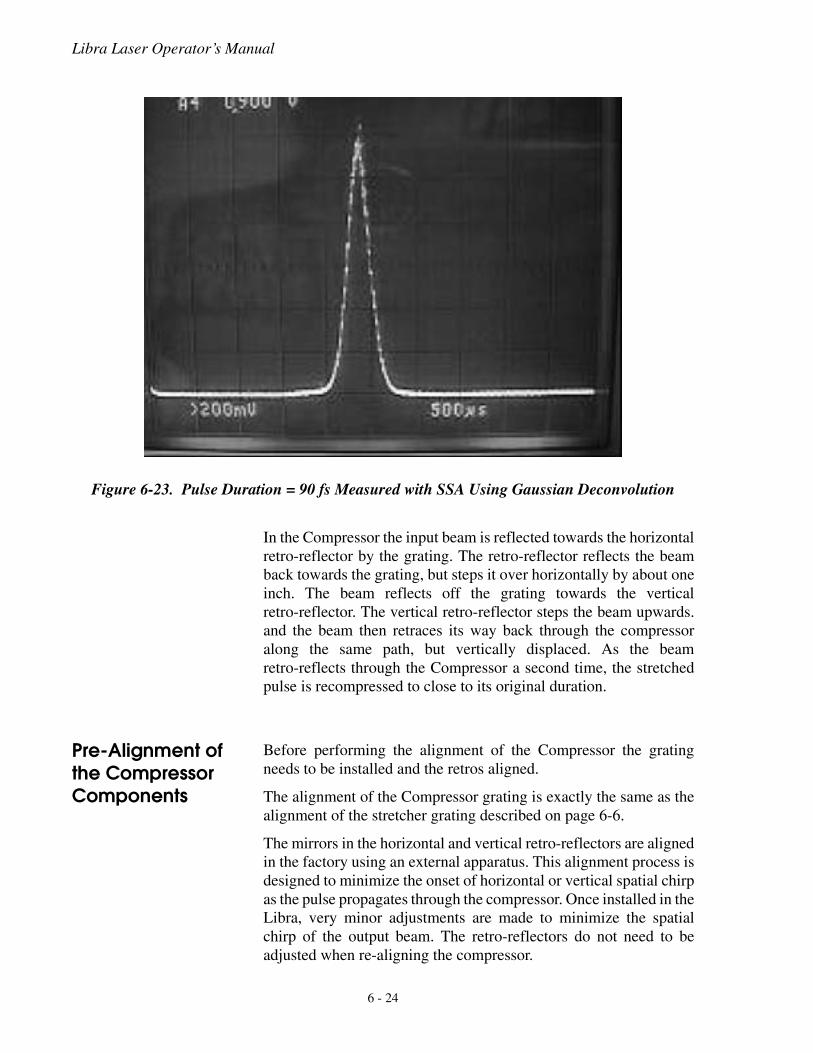
Libra Laser Operator’s Manual
In the Compressor the input beam is reflected towards the horizontalretro-reflector by the grating. The retro-reflector reflects the beamback towards the grating, but steps it over horizontally by about oneinch. The beam reflects off the grating towards the verticalretro-reflector. The vertical retro-reflector steps the beam upwards.and the beam then retraces its way back through the compressoralong the same path, but vertically displaced. As the beamretro-reflects through the Compressor a second time, the stretchedpulse is recompressed to close to its original duration.
Pre-Alignment of the Compressor Components
Before performing the alignment of the Compressor the gratingneeds to be installed and the retros aligned.
The alignment of the Compressor grating is exactly the same as thealignment of the stretcher grating described on page 6-6.
The mirrors in the horizontal and vertical retro-reflectors are alignedin the factory using an external apparatus. This alignment process isdesigned to minimize the onset of horizontal or vertical spatial chirpas the pulse propagates through the compressor. Once installed in theLibra, very minor adjustments are made to minimize the spatialchirp of the output beam. The retro-reflectors do not need to beadjusted when re-aligning the compressor.
Figure 6-23. Pulse Duration = 90 fs Measured with SSA Using Gaussian Deconvolution
6 - 24

Optical Alignment
Alignment of the Compressor with the Free- Running RA Beam
The alignment of the compressor is easily performed with unseededoutput from the RA. Refer to Figure 6-24. The alignment procedureis as follows:
Take great care not to accidentally clip the stretched spectrum.This may damage the optics in the RA. Most commonly thisoccurs by blocking part of the beam between SM5 and SM6, orbetween SM5 and the stretcher grating. Do not put your handsinside the stretcher while either Pockels cell is enabled.
1. Disable the Pockels cells from the SDG front panel.
2. If the compressor grating has not been previously rotated outof the way, record the position of the compressor grating.
Figure 6-24. Alignment of the Compressor with Free-Running Laser from RA
��
��� ������� ��
��
������������
��
��
��� ��
���
��
����
� ��
������
��
������
���
��
���
������
��
���
���
���
���
����
��
��� ���
��
��� ���
�� ���
���
��
�������
��
����
��
������
�������� !"�#�$%&!'!��
� �� ()����*$%��++*�
�����
���
����
6 - 25
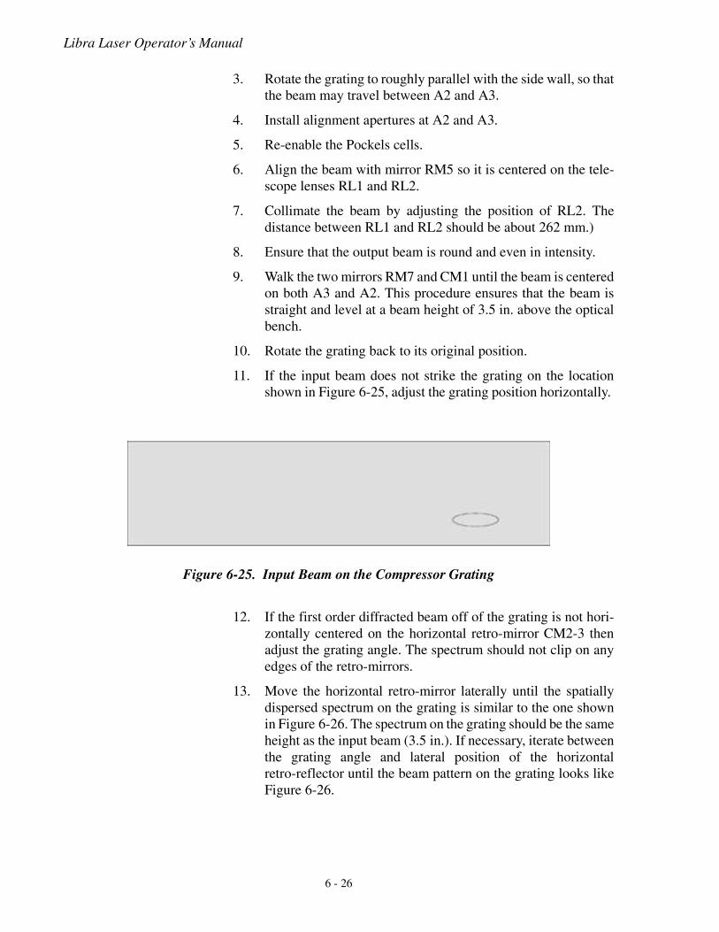
Libra Laser Operator’s Manual
3. Rotate the grating to roughly parallel with the side wall, so thatthe beam may travel between A2 and A3.
4. Install alignment apertures at A2 and A3.
5. Re-enable the Pockels cells.
6. Align the beam with mirror RM5 so it is centered on the tele-scope lenses RL1 and RL2.
7. Collimate the beam by adjusting the position of RL2. Thedistance between RL1 and RL2 should be about 262 mm.)
8. Ensure that the output beam is round and even in intensity.
9. Walk the two mirrors RM7 and CM1 until the beam is centeredon both A3 and A2. This procedure ensures that the beam isstraight and level at a beam height of 3.5 in. above the opticalbench.
10. Rotate the grating back to its original position.
11. If the input beam does not strike the grating on the locationshown in Figure 6-25, adjust the grating position horizontally.
12. If the first order diffracted beam off of the grating is not hori-zontally centered on the horizontal retro-mirror CM2-3 thenadjust the grating angle. The spectrum should not clip on anyedges of the retro-mirrors.
13. Move the horizontal retro-mirror laterally until the spatiallydispersed spectrum on the grating is similar to the one shownin Figure 6-26. The spectrum on the grating should be the sameheight as the input beam (3.5 in.). If necessary, iterate betweenthe grating angle and lateral position of the horizontalretro-reflector until the beam pattern on the grating looks likeFigure 6-26.
Figure 6-25. Input Beam on the Compressor Grating
6 - 26
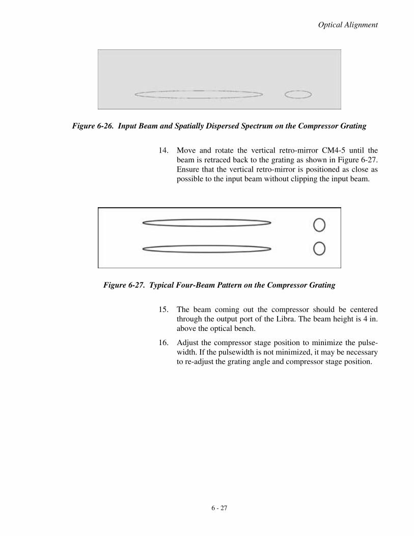
Optical Alignment
14. Move and rotate the vertical retro-mirror CM4-5 until thebeam is retraced back to the grating as shown in Figure 6-27.Ensure that the vertical retro-mirror is positioned as close aspossible to the input beam without clipping the input beam.
15. The beam coming out the compressor should be centeredthrough the output port of the Libra. The beam height is 4 in.above the optical bench.
16. Adjust the compressor stage position to minimize the pulse-width. If the pulsewidth is not minimized, it may be necessaryto re-adjust the grating angle and compressor stage position.
Figure 6-26. Input Beam and Spatially Dispersed Spectrum on the Compressor Grating
Figure 6-27. Typical Four-Beam Pattern on the Compressor Grating
6 - 27

Libra Laser Operator’s Manual
6 - 28
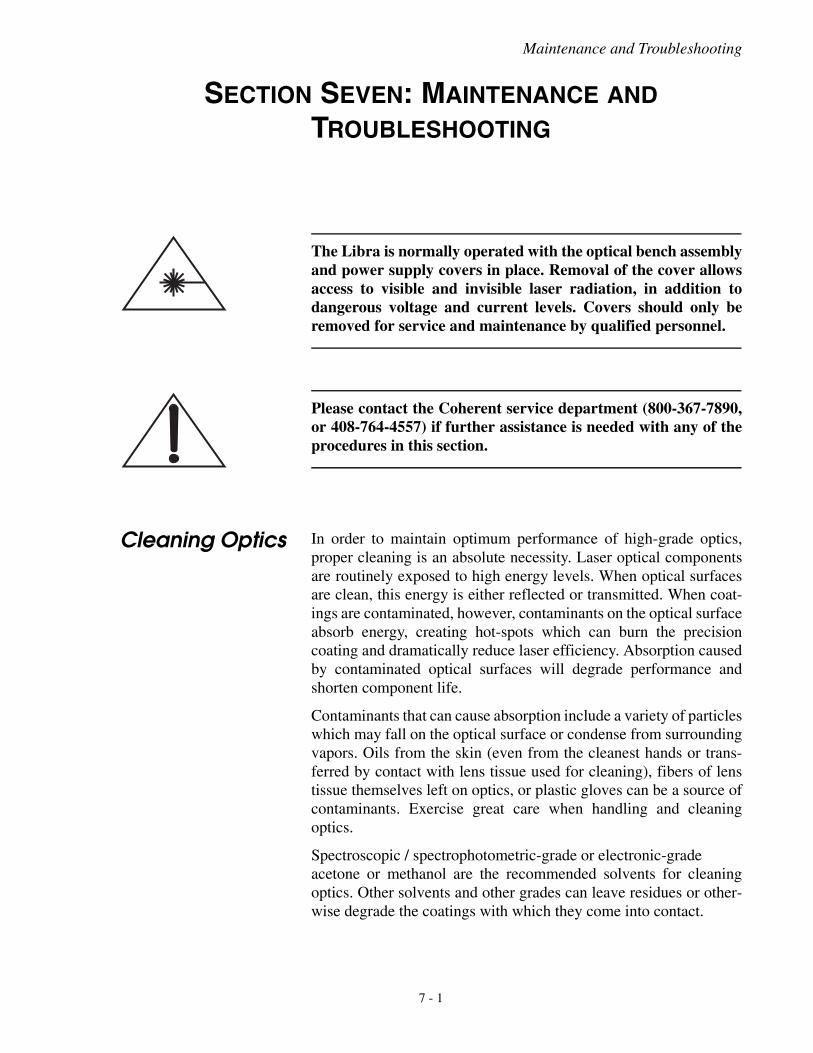
Maintenance and Troubleshooting
SECTION SEVEN: MAINTENANCE AND TROUBLESHOOTING
The Libra is normally operated with the optical bench assemblyand power supply covers in place. Removal of the cover allowsaccess to visible and invisible laser radiation, in addition todangerous voltage and current levels. Covers should only beremoved for service and maintenance by qualified personnel.
Please contact the Coherent service department (800-367-7890,or 408-764-4557) if further assistance is needed with any of theprocedures in this section.
Cleaning Optics In order to maintain optimum performance of high-grade optics,proper cleaning is an absolute necessity. Laser optical componentsare routinely exposed to high energy levels. When optical surfacesare clean, this energy is either reflected or transmitted. When coat-ings are contaminated, however, contaminants on the optical surfaceabsorb energy, creating hot-spots which can burn the precisioncoating and dramatically reduce laser efficiency. Absorption causedby contaminated optical surfaces will degrade performance andshorten component life.
Contaminants that can cause absorption include a variety of particleswhich may fall on the optical surface or condense from surroundingvapors. Oils from the skin (even from the cleanest hands or trans-ferred by contact with lens tissue used for cleaning), fibers of lenstissue themselves left on optics, or plastic gloves can be a source ofcontaminants. Exercise great care when handling and cleaningoptics.
Spectroscopic / spectrophotometric-grade or electronic-gradeacetone or methanol are the recommended solvents for cleaningoptics. Other solvents and other grades can leave residues or other-wise degrade the coatings with which they come into contact.
7 - 1
Libra Laser Operator’s Manual
Lens tissue of high quality is the recommended material for cleaningoptics. When cleaning optics with lens tissue, use each tissue foronly one pass in one direction and then discard it. Do not reuse atissue or swipe back in the opposite direction. Repeat if necessarywith a clean tissue, going in the same direction as the original swipe.Reusing tissue or going back in the opposite direction may lead todamage of the optic by dragging loose particles back across thesurface.
Do not attempt to clean holographic gratings or gold-coatedoptics. If it appears that these surfaces are contaminated contactCoherent service.
Cleaning Installed Optics
In the case of a large amount of dust visible on an optic, gentlyblowing a puff of air across an optic may be used as an initial step incleaning. However, do not use compressed air that contains propel-lants, do not blow with your mouth, and do not use anything thatcontains any other residue or which may cause condensation on theoptic. Also, be careful not to stir up dust into the air which may thensettle on an optic.
The following procedure is used to clean optics in place in the laserhead. When possible, clean the optic while it is installed in the laserhead to minimize disturbance to the optical alignment.
1. Disable or block the laser beam.
2. Neatly fold a sheet of lens tissue several times into a rectan-gular shape (Figure 7-1a & b), ending with a folded edge thatis 1/4 inch to 3/4 inch long, clamped with a hemostat, withapproximately 1/8 inch of the tissue paper protruding from theside of the hemostat (Figure 7-1c). While folding the tissue becareful not to contaminate the tissue with soiled or oily fingersin the place the tissue will eventually touch the optic to becleaned. To avoid scratching an optic, ensure that the hemostatis not clamped too close to the fold of the lens tissue.
7 - 2
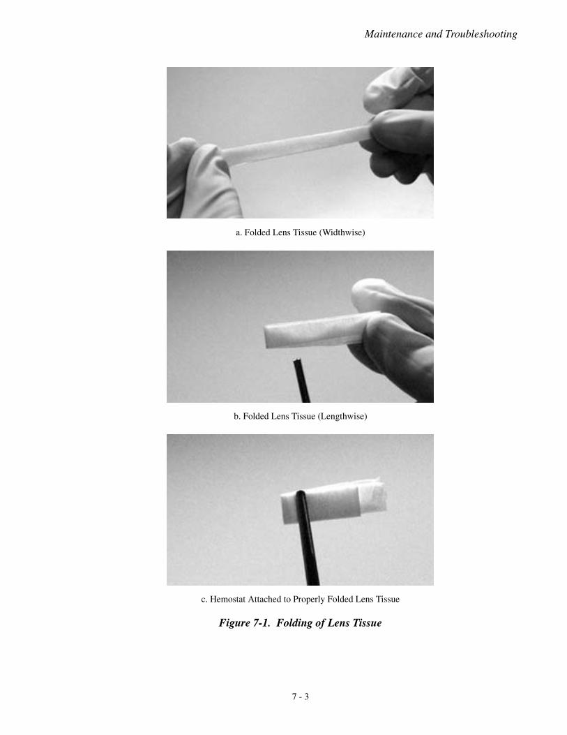
Maintenance and Troubleshooting
a. Folded Lens Tissue (Widthwise)
b. Folded Lens Tissue (Lengthwise)
c. Hemostat Attached to Properly Folded Lens Tissue
Figure 7-1. Folding of Lens Tissue
7 - 3
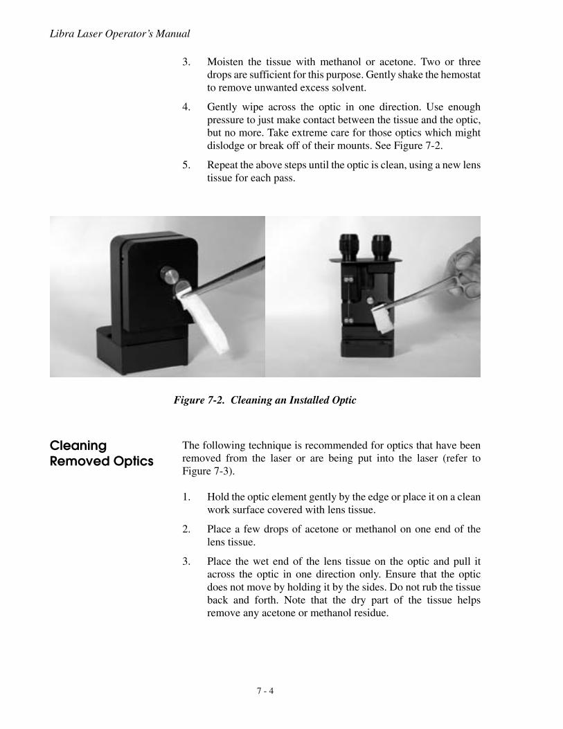
Libra Laser Operator’s Manual
3. Moisten the tissue with methanol or acetone. Two or threedrops are sufficient for this purpose. Gently shake the hemostatto remove unwanted excess solvent.
4. Gently wipe across the optic in one direction. Use enoughpressure to just make contact between the tissue and the optic,but no more. Take extreme care for those optics which mightdislodge or break off of their mounts. See Figure 7-2.
5. Repeat the above steps until the optic is clean, using a new lenstissue for each pass.
Cleaning Removed Optics
The following technique is recommended for optics that have beenremoved from the laser or are being put into the laser (refer toFigure 7-3).
1. Hold the optic element gently by the edge or place it on a cleanwork surface covered with lens tissue.
2. Place a few drops of acetone or methanol on one end of thelens tissue.
3. Place the wet end of the lens tissue on the optic and pull itacross the optic in one direction only. Ensure that the opticdoes not move by holding it by the sides. Do not rub the tissueback and forth. Note that the dry part of the tissue helpsremove any acetone or methanol residue.
Figure 7-2. Cleaning an Installed Optic
7 - 4
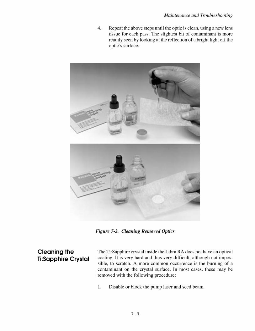
Maintenance and Troubleshooting
4. Repeat the above steps until the optic is clean, using a new lenstissue for each pass. The slightest bit of contaminant is morereadily seen by looking at the reflection of a bright light off theoptic’s surface.
Cleaning the Ti:Sapphire Crystal
The Ti:Sapphire crystal inside the Libra RA does not have an opticalcoating. It is very hard and thus very difficult, although not impos-sible, to scratch. A more common occurrence is the burning of acontaminant on the crystal surface. In most cases, these may beremoved with the following procedure:
1. Disable or block the pump laser and seed beam.
Figure 7-3. Cleaning Removed Optics
7 - 5

Libra Laser Operator’s Manual
2. Prepare the lens tissue paper as described above (See“Cleaning Installed Optics” on page 7-2).
3. Gently wipe one of the surfaces of the crystal. Be careful notto drag any of the excess soft metal, located between thecrystal and its aluminum mount, across the crystal face.
4. Replace the tissue and wipe the second face.
5. Visually verify that the contaminant has been removed and thatyou have not soiled the surface.
Stretcher and Compressor Grating, and Stretcher Gold Mirror Cleanliness
These three components are very delicate and easily damaged.Coherent does not recommend any contact cleaning procedures. Nosolvents should ever be used in any way. If a portion of one of thegratings or the gold mirror is soiled or damaged, gently direct a smallpuff of air across the surface.
Cleaning the Pockels Cells
The optical surfaces of the Pockels cells are coated and can be safelycleaned using the same process as cleaning installed optics.However, it is very difficult to reach the optical surfaces when thePockels cell is installed in the laser. In order to properly clean thecell’s surfaces it is necessary to remove them. For this reasonCoherent does not recommend the cleaning of the Pockels cells. Ifyou are concerned about the cleanliness of the Pockels cells, pleasecontact a Coherent service representative.
7 - 6
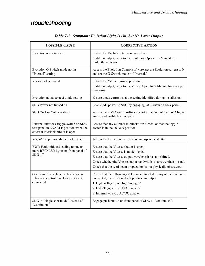
Maintenance and Troubleshooting
Troubleshooting
Table 7-1. Symptom: Emission Light Is On, but No Laser Output
POSSIBLE CAUSE CORRECTIVE ACTION
Evolution not activated Initiate the Evolution turn-on procedure.
If still no output, refer to the Evolution Operator’s Manual for in-depth diagnosis.
Evolution Q-Switch mode not in “Internal” setting
Access the Evolution Control software, set the Evolution current to 0, and set the Q-Switch mode to “Internal.”
Vitesse not activated Initiate the Vitesse turn-on procedure.
If still no output, refer to the Vitesse Operator’s Manual for in-depth diagnosis.
Evolution not at correct diode setting Ensure diode current is at the setting identified during installation.
SDG Power not turned on Enable AC power to SDG by engaging AC switch on back panel.
SDG Out1 or Out2 disabled Access the SDG Control software, verify that both of the BWD lights are lit, and enable both outputs.
External interlock toggle switch on SDG rear panel in ENABLE position when the external interlock circuit is open
Ensure that any external interlocks are closed, or that the toggle switch is in the DOWN position.
Regen/Compressor shutter not opened Access the Libra control software and open the shutter.
BWD Fault initiated leading to one or more BWD LED lights on front panel of SDG off
Ensure that the Vitesse shutter is open.
Ensure that the Vitesse is mode-locked.
Ensure that the Vitesse output wavelength has not shifted.
Check whether the Vitesse output bandwidth is narrower than normal.
Check that the seed beam propagation is not physically obstructed.
One or more interface cables between Libra rear control panel and SDG not connected
Check that the following cables are connected. If any of them are not connected, the Libra will not produce an output.
1. High Voltage 1 or High Voltage 2
2. HSD Trigger 1 or HSD Trigger 2
3. External +12vdc AC/DC adapter
SDG in “single shot mode” instead of “Continuous”
Engage push button on front panel of SDG to “continuous”.
7 - 7
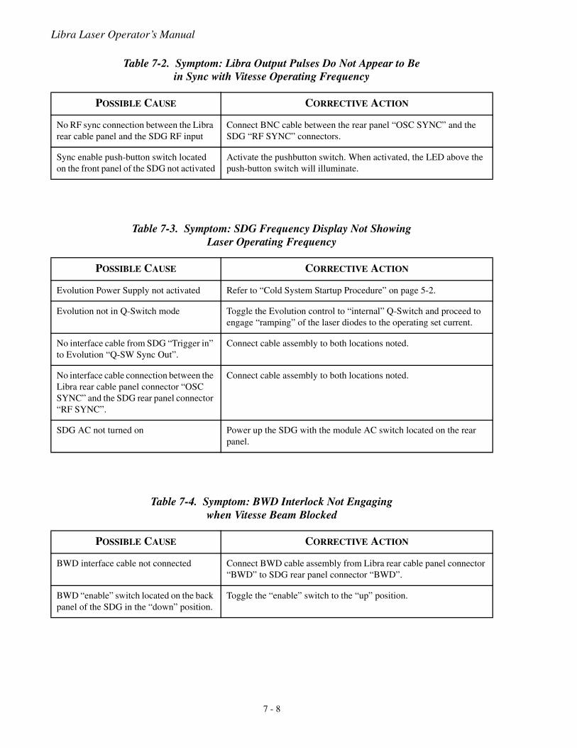
Libra Laser Operator’s Manual
Table 7-2. Symptom: Libra Output Pulses Do Not Appear to Be in Sync with Vitesse Operating Frequency
POSSIBLE CAUSE CORRECTIVE ACTION
No RF sync connection between the Libra rear cable panel and the SDG RF input
Connect BNC cable between the rear panel “OSC SYNC” and the SDG “RF SYNC” connectors.
Sync enable push-button switch located on the front panel of the SDG not activated
Activate the pushbutton switch. When activated, the LED above the push-button switch will illuminate.
Table 7-3. Symptom: SDG Frequency Display Not ShowingLaser Operating Frequency
POSSIBLE CAUSE CORRECTIVE ACTION
Evolution Power Supply not activated Refer to “Cold System Startup Procedure” on page 5-2.
Evolution not in Q-Switch mode Toggle the Evolution control to “internal” Q-Switch and proceed to engage “ramping” of the laser diodes to the operating set current.
No interface cable from SDG “Trigger in” to Evolution “Q-SW Sync Out”.
Connect cable assembly to both locations noted.
No interface cable connection between the Libra rear cable panel connector “OSC SYNC” and the SDG rear panel connector “RF SYNC”.
Connect cable assembly to both locations noted.
SDG AC not turned on Power up the SDG with the module AC switch located on the rear panel.
Table 7-4. Symptom: BWD Interlock Not Engagingwhen Vitesse Beam Blocked
POSSIBLE CAUSE CORRECTIVE ACTION
BWD interface cable not connected Connect BWD cable assembly from Libra rear cable panel connector “BWD” to SDG rear panel connector “BWD”.
BWD “enable” switch located on the back panel of the SDG in the “down” position.
Toggle the “enable” switch to the “up” position.
7 - 8
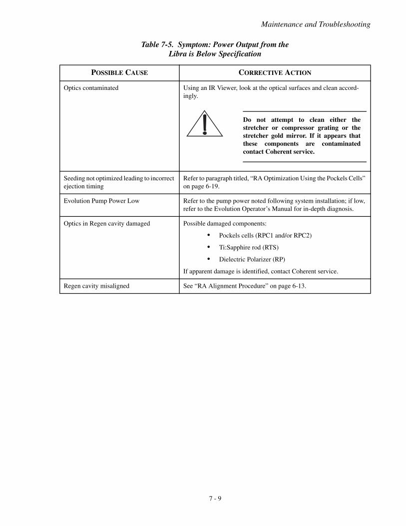
Maintenance and Troubleshooting
Table 7-5. Symptom: Power Output from theLibra is Below Specification
POSSIBLE CAUSE CORRECTIVE ACTION
Optics contaminated Using an IR Viewer, look at the optical surfaces and clean accord-ingly.
Do not attempt to clean either thestretcher or compressor grating or thestretcher gold mirror. If it appears thatthese components are contaminatedcontact Coherent service.
Seeding not optimized leading to incorrect ejection timing
Refer to paragraph titled, “RA Optimization Using the Pockels Cells” on page 6-19.
Evolution Pump Power Low Refer to the pump power noted following system installation; if low, refer to the Evolution Operator’s Manual for in-depth diagnosis.
Optics in Regen cavity damaged Possible damaged components:
• Pockels cells (RPC1 and/or RPC2)
• Ti:Sapphire rod (RTS)
• Dielectric Polarizer (RP)
If apparent damage is identified, contact Coherent service.
Regen cavity misaligned See “RA Alignment Procedure” on page 6-13.
7 - 9
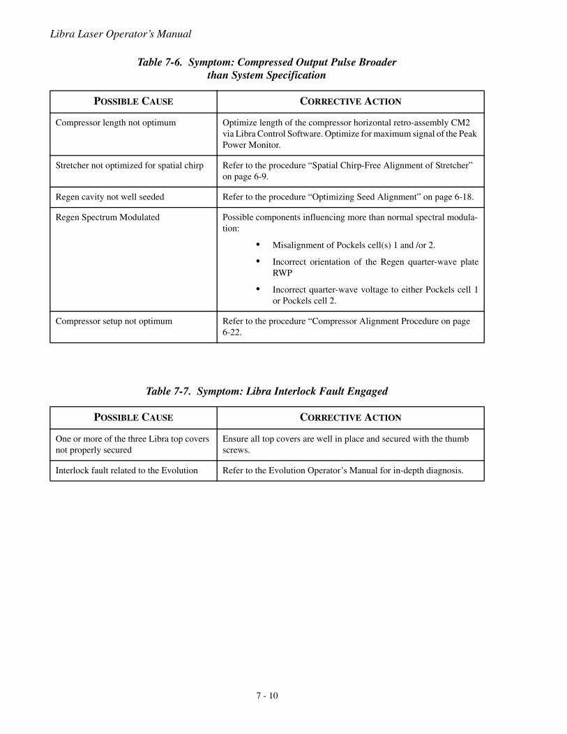
Libra Laser Operator’s Manual
Table 7-6. Symptom: Compressed Output Pulse Broaderthan System Specification
POSSIBLE CAUSE CORRECTIVE ACTION
Compressor length not optimum Optimize length of the compressor horizontal retro-assembly CM2 via Libra Control Software. Optimize for maximum signal of the Peak Power Monitor.
Stretcher not optimized for spatial chirp Refer to the procedure “Spatial Chirp-Free Alignment of Stretcher” on page 6-9.
Regen cavity not well seeded Refer to the procedure “Optimizing Seed Alignment” on page 6-18.
Regen Spectrum Modulated Possible components influencing more than normal spectral modula-tion:
• Misalignment of Pockels cell(s) 1 and /or 2.
• Incorrect orientation of the Regen quarter-wave plateRWP
• Incorrect quarter-wave voltage to either Pockels cell 1or Pockels cell 2.
Compressor setup not optimum Refer to the procedure “Compressor Alignment Procedure on page 6-22.
Table 7-7. Symptom: Libra Interlock Fault Engaged
POSSIBLE CAUSE CORRECTIVE ACTION
One or more of the three Libra top covers not properly secured
Ensure all top covers are well in place and secured with the thumb screws.
Interlock fault related to the Evolution Refer to the Evolution Operator’s Manual for in-depth diagnosis.
7 - 10
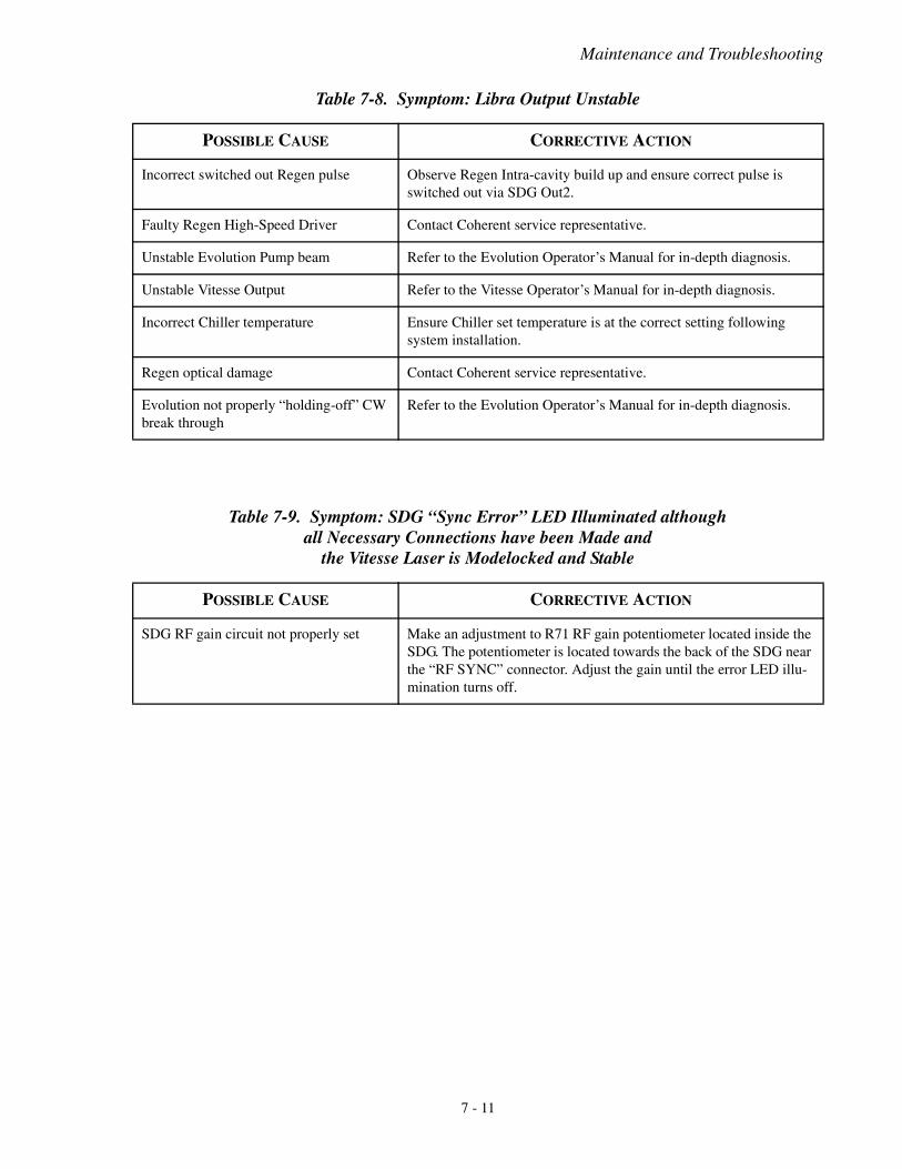
Maintenance and Troubleshooting
Table 7-8. Symptom: Libra Output Unstable
POSSIBLE CAUSE CORRECTIVE ACTION
Incorrect switched out Regen pulse Observe Regen Intra-cavity build up and ensure correct pulse is switched out via SDG Out2.
Faulty Regen High-Speed Driver Contact Coherent service representative.
Unstable Evolution Pump beam Refer to the Evolution Operator’s Manual for in-depth diagnosis.
Unstable Vitesse Output Refer to the Vitesse Operator’s Manual for in-depth diagnosis.
Incorrect Chiller temperature Ensure Chiller set temperature is at the correct setting following system installation.
Regen optical damage Contact Coherent service representative.
Evolution not properly “holding-off” CW break through
Refer to the Evolution Operator’s Manual for in-depth diagnosis.
Table 7-9. Symptom: SDG “Sync Error” LED Illuminated althoughall Necessary Connections have been Made and
the Vitesse Laser is Modelocked and Stable
POSSIBLE CAUSE CORRECTIVE ACTION
SDG RF gain circuit not properly set Make an adjustment to R71 RF gain potentiometer located inside the SDG. The potentiometer is located towards the back of the SDG near the “RF SYNC” connector. Adjust the gain until the error LED illu-mination turns off.
7 - 11

Libra Laser Operator’s Manual
7 - 12
Basic Theory
SECTION EIGHT: BASIC THEORY
Ti:Sapphire Laser Theory
The Ti3+ titanium ion is responsible for the laser action ofTi:sapphire. Ti:sapphire is a crystalline material produced by intro-ducing Ti2O3 into a melt of Al2O3. A boule of material is grownfrom the melt where Ti3+ ions are substituted for a small percentageof the Al3+ ions. The electronic ground state of the Ti3+ ion is splitinto a pair of vibrationally broadened levels. Absorption transitionsoccur over a broad range of wavelengths from 400 to 600 nm. Fluo-rescence transitions occur from the lower vibrational levels of theexcited state to the upper vibrational levels of the ground state.
Although the fluorescence band extends to wavelengths shorter than600 nm, the long wavelength side of the absorption band overlapsthe short wavelength end of the fluorescence spectrum. Therefore,lasing is only possible at wavelengths longer than 660 nm. An addi-tional weak absorption band that overlaps the fluorescence spectrumfurther reduces the tuning range. Additionally, the tuning range isaffected by mirror coatings, intra-cavity optics, pump power, andother factors.
Chirped Pulse Amplification
Ti:sapphire amplifiers have high saturation fluences which make itpossible to extract relatively high energies from modest-scale lasersystems. Ti:sapphire also has a large gain bandwidth which isneeded to amplify subpicosecond pulses. A limitation comes fromthe tendency of bright beams to self-focus destructively (a result ofnon-linearity in the index of refraction), which makes it necessary tolimit the intensity present in amplifiers of reasonable length to lessthan 10 GW/cm2.
The technique of chirped pulse amplification (CPA) is used in theLibra and removes this obstacle. A short low-energy seed pulse istemporally stretched to increase its pulsewidth by as much as 10,000times - thus significantly reducing its brightness or peak power. Thislow brightness seed pulse is then injected into the regenerativeamplifier and the pulse energy increases by up to a factor of 106.Following amplification, the pulse is ejected and recompressed tonear its original duration.
8 - 1
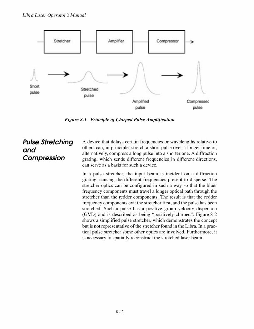
Libra Laser Operator’s Manual
Pulse Stretching and Compression
A device that delays certain frequencies or wavelengths relative toothers can, in principle, stretch a short pulse over a longer time or,alternatively, compress a long pulse into a shorter one. A diffractiongrating, which sends different frequencies in different directions,can serve as a basis for such a device.
In a pulse stretcher, the input beam is incident on a diffractiongrating, causing the different frequencies present to disperse. Thestretcher optics can be configured in such a way so that the bluerfrequency components must travel a longer optical path through thestretcher than the redder components. The result is that the redderfrequency components exit the stretcher first, and the pulse has beenstretched. Such a pulse has a positive group velocity dispersion(GVD) and is described as being “positively chirped”. Figure 8-2shows a simplified pulse stretcher, which demonstrates the conceptbut is not representative of the stretcher found in the Libra. In a prac-tical pulse stretcher some other optics are involved. Furthermore, itis necessary to spatially reconstruct the stretched laser beam.
Figure 8-1. Principle of Chirped Pulse Amplification
8 - 2
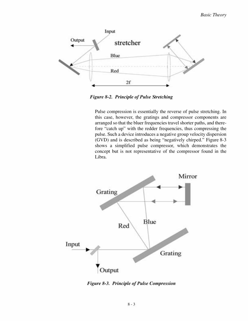
Basic Theory
Pulse compression is essentially the reverse of pulse stretching. Inthis case, however, the gratings and compressor components arearranged so that the bluer frequencies travel shorter paths, and there-fore “catch up” with the redder frequencies, thus compressing thepulse. Such a device introduces a negative group velocity dispersion(GVD) and is described as being “negatively chirped.” Figure 8-3shows a simplified pulse compressor, which demonstrates theconcept but is not representative of the compressor found in theLibra.
Figure 8-2. Principle of Pulse Stretching
Figure 8-3. Principle of Pulse Compression
8 - 3
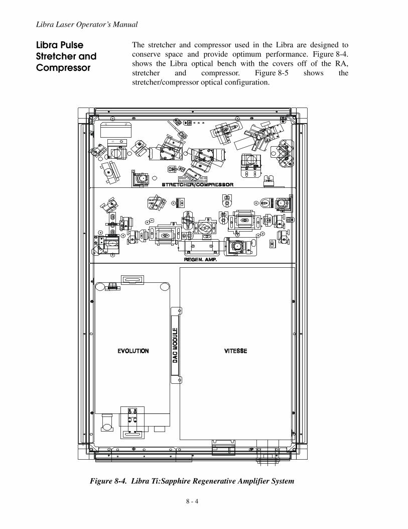
Libra Laser Operator’s Manual
Libra Pulse Stretcher and Compressor
The stretcher and compressor used in the Libra are designed toconserve space and provide optimum performance. Figure 8-4.shows the Libra optical bench with the covers off of the RA,stretcher and compressor. Figure 8-5 shows thestretcher/compressor optical configuration.
Figure 8-4. Libra Ti:Sapphire Regenerative Amplifier System
8 - 4
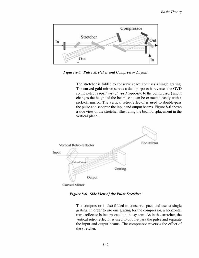
Basic Theory
The stretcher is folded to conserve space and uses a single grating.The curved gold mirror serves a dual purpose: it reverses the GVDso the pulse is positively chirped (opposite to the compressor) and itchanges the height of the beam so it can be extracted easily with apick-off mirror. The vertical retro-reflector is used to double-passthe pulse and separate the input and output beams. Figure 8-6 showsa side view of the stretcher illustrating the beam displacement in thevertical plane.
The compressor is also folded to conserve space and uses a singlegrating. In order to use one grating for the compressor, a horizontalretro-reflector is incorporated in the system. As in the stretcher, thevertical retro-reflector is used to double-pass the pulse and separatethe input and output beams. The compressor reverses the effect ofthe stretcher.
Figure 8-5. Pulse Stretcher and Compressor Layout
Figure 8-6. Side View of the Pulse Stretcher
8 - 5
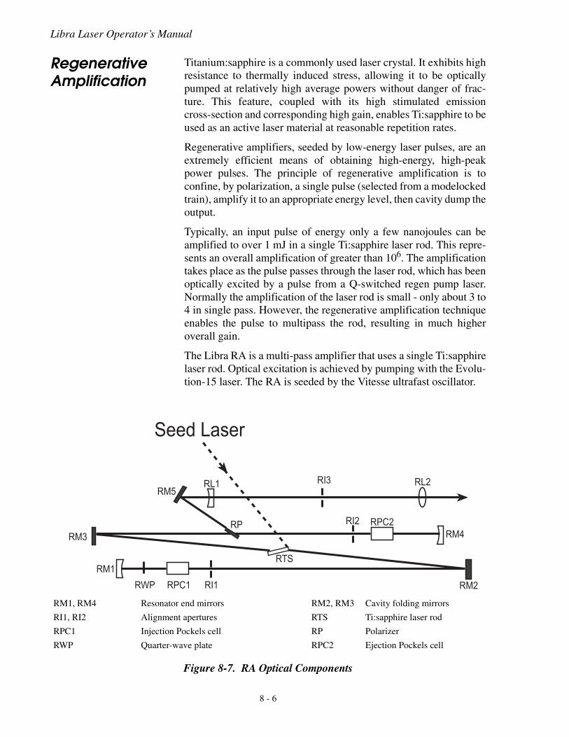
Libra Laser Operator’s Manual
Regenerative Amplification
Titanium:sapphire is a commonly used laser crystal. It exhibits highresistance to thermally induced stress, allowing it to be opticallypumped at relatively high average powers without danger of frac-ture. This feature, coupled with its high stimulated emissioncross-section and corresponding high gain, enables Ti:sapphire to beused as an active laser material at reasonable repetition rates.
Regenerative amplifiers, seeded by low-energy laser pulses, are anextremely efficient means of obtaining high-energy, high-peakpower pulses. The principle of regenerative amplification is toconfine, by polarization, a single pulse (selected from a modelockedtrain), amplify it to an appropriate energy level, then cavity dump theoutput.
Typically, an input pulse of energy only a few nanojoules can beamplified to over 1 mJ in a single Ti:sapphire laser rod. This repre-sents an overall amplification of greater than 106. The amplificationtakes place as the pulse passes through the laser rod, which has beenoptically excited by a pulse from a Q-switched regen pump laser.Normally the amplification of the laser rod is small - only about 3 to4 in single pass. However, the regenerative amplification techniqueenables the pulse to multipass the rod, resulting in much higheroverall gain.
The Libra RA is a multi-pass amplifier that uses a single Ti:sapphirelaser rod. Optical excitation is achieved by pumping with the Evolu-tion-15 laser. The RA is seeded by the Vitesse ultrafast oscillator.
RM1, RM4
RI1, RI2
RPC1
RWP
Resonator end mirrors
Alignment apertures
Injection Pockels cell
Quarter-wave plate
RM2, RM3
RTS
RP
RPC2
Cavity folding mirrors
Ti:sapphire laser rod
Polarizer
Ejection Pockels cell
Figure 8-7. RA Optical Components
���
���
��� ���� ���
���
��
��� ���
�� ��� ���
��
��
��
���-#��+��
8 - 6
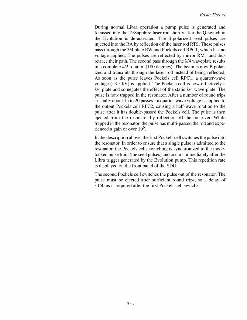
Basic Theory
During normal Libra operation a pump pulse is generated andfocussed into the Ti:Sapphire laser rod shortly after the Q-switch inthe Evolution is de-activated. The S-polarized seed pulses areinjected into the RA by reflection off the laser rod RTS. These pulsespass through the λ/4 plate RW and Pockels cell RPC1, which has novoltage applied. The pulses are reflected by mirror RM1 and thusretrace their path. The second pass through the λ/4 waveplate resultsin a complete λ/2 rotation (180 degrees). The beam is now P-polar-ized and transmits through the laser rod instead of being reflected.As soon as the pulse leaves Pockels cell RPC1, a quarter-wavevoltage (~3.5 kV) is applied. The Pockels cell is now effectively aλ/4 plate and so negates the effect of the static λ/4 wave-plate. Thepulse is now trapped in the resonator. After a number of round trips− usually about 15 to 20 passes − a quarter-wave voltage is applied tothe output Pockels cell RPC2, causing a half-wave rotation to thepulse after it has double-passed the Pockels cell. The pulse is thenejected from the resonator by reflection off the polarizer. Whiletrapped in the resonator, the pulse has multi-passed the rod and expe-rienced a gain of over 106.
In the description above, the first Pockels cell switches the pulse intothe resonator. In order to ensure that a single pulse is admitted to theresonator, the Pockels cells switching is synchronized to the mode-locked pulse train (the seed pulses) and occurs immediately after theLibra trigger generated by the Evolution pump. This repetition rateis displayed on the front panel of the SDG.
The second Pockels cell switches the pulse out of the resonator. Thepulse must be ejected after sufficient round trips, so a delay of~150 ns is required after the first Pockels cell switches.
8 - 7
Libra Laser Operator’s Manual
Bandwidth Detector (BWD)
The SDG has a “+ 5 VDC Enable” on the back that is connected toa bandwidth detector (BWD) interlock. When the interlock istripped, the output of the Libra is disabled by interrupting the trig-gers to the Pockels cells.
Overview Excessive peak optical powers resulting from improper or insuffi-cient temporal stretching of the seed laser pulses can lead to opticaldamage of some of the RA components. The Coherent BWD isdesigned to protect the amplifier from an improperly conditionedinput seed pulse. There are two ways in which the input seed pulsecan be defective:
1. The available spectral bandwidth is truncated inside the Libraenclosure.
2. The seed laser is not outputting sufficient bandwidth.
The first of the above scenarios can occur if the user accidentallyrestricts the propagation of the seed pulse throughout the stretcherset-up. Specifically, if part of the spectrum is blocked but the rest isunintentionally allowed to continue seeding the Regen cavity,damage will occur.
The second of these scenarios refers to a misaligned or unstable seedlaser. If the instantaneous bandwidth of the seed system falls belowthe designed stretcher tolerances, it may not be possible to producesufficient temporal chirp needed to protect the Regen amplifiercomponents. The synchronization system of the SDG will protectthe amplifier from most − but not all − situations in which mode-locking fails or is unstable.
The internal BWD is an integrated part of the stretcher.
8 - 8
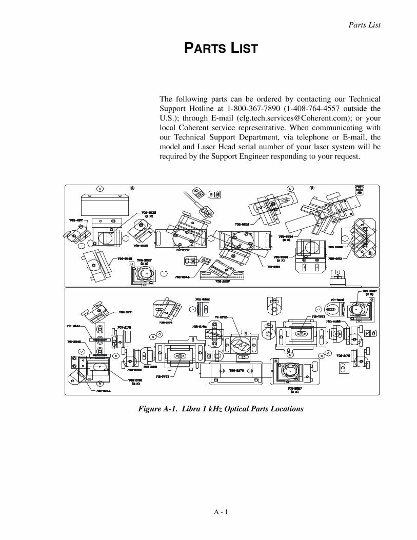
Parts List
PARTS LIST
The following parts can be ordered by contacting our TechnicalSupport Hotline at 1-800-367-7890 (1-408-764-4557 outside theU.S.); through E-mail ([email protected]); or yourlocal Coherent service representative. When communicating withour Technical Support Department, via telephone or E-mail, themodel and Laser Head serial number of your laser system will berequired by the Support Engineer responding to your request.
Figure A-1. Libra 1 kHz Optical Parts Locations
A - 1
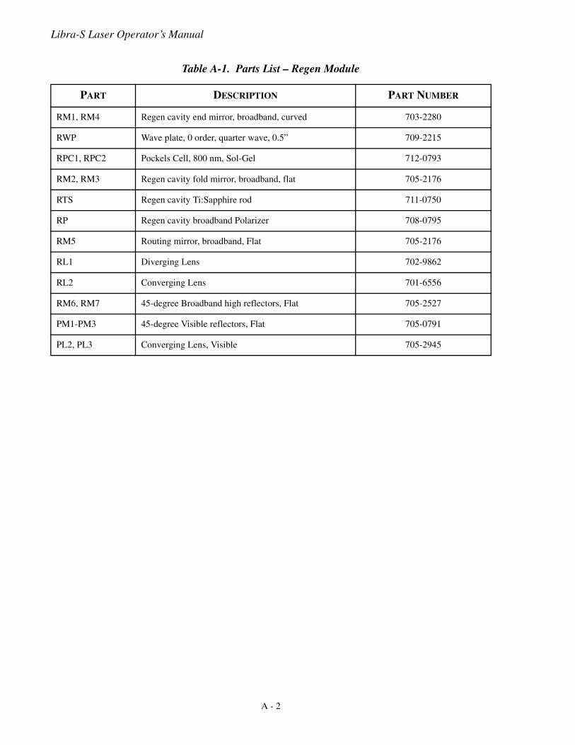
Libra-S Laser Operator’s Manual
Table A-1. Parts List – Regen Module
PART DESCRIPTION PART NUMBER
RM1, RM4 Regen cavity end mirror, broadband, curved 703-2280
RWP Wave plate, 0 order, quarter wave, 0.5” 709-2215
RPC1, RPC2 Pockels Cell, 800 nm, Sol-Gel 712-0793
RM2, RM3 Regen cavity fold mirror, broadband, flat 705-2176
RTS Regen cavity Ti:Sapphire rod 711-0750
RP Regen cavity broadband Polarizer 708-0795
RM5 Routing mirror, broadband, Flat 705-2176
RL1 Diverging Lens 702-9862
RL2 Converging Lens 701-6556
RM6, RM7 45-degree Broadband high reflectors, Flat 705-2527
PM1-PM3 45-degree Visible reflectors, Flat 705-0791
PL2, PL3 Converging Lens, Visible 705-2945
A - 2
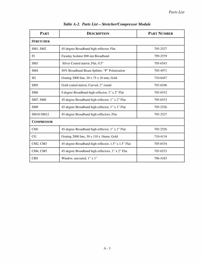
Parts List
Table A-2. Parts List – Stretcher/Compressor Module
PART DESCRIPTION PART NUMBER
STRETCHER
SM1, SM2 45-degree Broadband high reflector, Flat 705-2527
FI Faraday Isolator 800 nm Broadband 799-2579
SM3 Silver Coated mirror, Flat, 0.5” 705-6543
SM4 50% Broadband Beam Splitter, “P” Polarization 705-4971
SG Grating 2000 line, 30 x 75 x 16 mm, Gold 710-6447
SM5 Gold coated mirror, Curved, 2” round 703-6548
SM6 0 degree Broadband high reflector, 1” x 2” Flat 705-6532
SM7, SM8 45-degree Broadband high reflector, 1” x 2” Flat 705-6533
SM9 45-degree Broadband high reflector, 1” x 1” Flat 705-2526
SM10-SM12 45-degree Broadband high reflectors, Flat 705-2527
COMPRESSOR
CM1 45-degree Broadband high reflector, 1” x 1” Flat 705-2526
CG Grating 2000 line, 30 x 110 x 16mm, Gold 710-4134
CM2, CM3 45-degree Broadband high reflector, 1.5” x 1.5” Flat 705-6534
CM4, CM5 45-degree Broadband high reflectors, 1” x 2” Flat 705-6533
CBS Window, uncoated, 1” x 1” 706-4183
A - 3

Libra-S Laser Operator’s Manual
A - 4
Warranty
WARRANTY
Coherent, Inc. warrants to the original purchaser (the Buyer) only,that the laser system, that is the subject of this sale, (a) conforms toCoherent's published specifications and (b) is free from defects inmaterials and workmanship.
Laser systems are warranted to conform to Coherent's publishedspecifications and to be free from defects in materials and workman-ship for a period of twelve (12) months. This warranty covers travelexpenses for the first ninety (90) days. For systems that includeinstallation in the purchase price, this warranty begins at installationor thirty (30) days from shipment, whichever occurs first. Forsystems which do not include installation, this warranty begins atdate of shipment.
Optical Products
Coherent optical products are unconditionally warranted to be freeof defects in materials and workmanship. Discrepancies must bereported to Coherent within thirty (30) days of receipt, and returnedto Coherent within ninety (90) days. Adjustment is limited toreplacement, refund or repair at Coherent's option.
Conditions of Warranty
On-site warranty services are provided only at the installation point.If products eligible for on-site warranty and installation services aremoved from the original installation point, the warranty will remainin effect only if the Buyer purchases additional inspection or instal-lation services at the new site.
For warranty service requiring the return of any product to Coherent,the product must be returned to a service facility designated byCoherent. The Buyer is responsible for all shipping charges, taxesand duties covered under warranty service.
Parts replaced under warranty shall become the property of Coherentand must be returned to Coherent, Inc., Santa Clara, or to a facilitydesignated by Coherent. The Buyer will be obligated to issue apurchase order for the value of the replaced parts and Coherent willissue credit when the parts are received.
B - 1
Libra-S Laser Operator’s Manual
Other Products Other products not specifically listed above are warranted to, (a)conform to Coherent's published specifications and (b) be free fromdefects in materials and workmanship. This warranty covers partsand labor and is for a period of twelve (12) months from the date ofshipment.
Responsibilities of the Buyer
The Buyer must provide the appropriate utilities and operating envi-ronment outlined in the product literature and/or the Pre-installationManual. Damage to the laser system caused by failure of Buyer’sutilities or the Buyer's failure to maintain an appropriate operatingenvironment, is solely the responsibility of the Buyer and is specifi-cally excluded from any warranty, warranty extension, or serviceagreement.
The Buyer is responsible for prompt notification to Coherent of anyclaims made under warranty. In no event will Coherent be respon-sible for warranty claims later than seven (7) days after the expira-tion of the warranty.
Limitations of Warranty
The foregoing warranty shall not apply to defects resulting from:
1. Components or accessories with separate warranties manufac-tured by companies other than Coherent.
2. Improper or inadequate maintenance by Buyer.
3. Buyer-supplied interfacing.
4. Operation outside the environmental specifications of theproduct.
5. Improper site preparation and maintenance.
6. Unauthorized modification or misuse.
Coherent assumes no responsibility for customer-supplied material.
The obligations of Coherent are limited to repairing or replacing,without charge, equipment which proves to be defective during thewarranty period. Repaired or replaced parts are warranted for theduration of the original warranty period only. This warranty does notcover damage due to misuse, negligence or accidents, or damage dueto installations, repairs or adjustments not specifically authorized byCoherent.
B - 2

Warranty
This warranty applies only to the original Buyer at the initial instal-lation point in the country of purchase, unless otherwise specified inthe sales contract. Warranty is transferable to another location or toanother Buyer only by special agreement which will include addi-tional inspection or installation at the new site.
THE WARRANTY SET FORTH ABOVE IS EXCLUSIVE INLIEU OF ALL OTHER WARRANTY, WHETHER WRITTEN,ORAL OR IMPLIED, AND DOES NOT COVER INCIDENTALOR CONSEQUENTIAL LOSS. COHERENT SPECIFICALLYDISCLAIMS THE IMPLIED WARRANTIES OF MERCHANT-ABILITY AND FITNESS FOR A PARTICULAR PURPOSE.
B - 3

Libra-S Laser Operator’s Manual
B - 4

Glossary
GLOSSARY
°C Degrees centigrade or Celsius°F Degrees Fahrenheitμ Microns (10-6)μrad Microradian(s)μsec Microsecond(s)1/e2 Beam diameter parameterλ Wavelength
AC Alternating currentAGC Automatic gain controlAmp Amperes
BPF Band pass filterBWD Bandwidth Detector
CDRH Center for Devices and Radiological Healthcm Centimeter(s)CPA Chirped Pulse AmplificationCW Continuous wave
DC Direct current
EMC Electromagnetic compliance
fs femtosecond or 10-15 second
GHz GigahertzGVD Group Velocity Dispersion
HSPS High speed power supplyHz Hertz
IR InfraredIR viewer Infrared viewer
kg Kilogram(s)kHz Kilohertz
LED Light emitting diodeLVD Low voltage directive
m Meter(s)mAmp Milliampere(s)MHz Megahertzmm Millimeter(s)mrad Milliradian(s)msec Millisecond(s)mV Millivolt(s)mW Milliwatt(s)
Glossary - 1
Libra-S Laser Operator’s Manual
Nd:YAG Neodymium doped yttrium aluminum garnetnm Nanometer(s)
OEM Original equipment manufacturer
ps picosecond or 10-12 secondPZT piezo-electric transducer
RA or regen Regenerative AmplifierRF Radio frequencyrms Root mean squareRx Receive
SDG Synchronization and Delay Generator
TEM Transverse electromagnetic (cross-sectional laser beam mode)Ti:Sapphire Titanium-doped SapphireTx Transmit
VAC Volts, alternating currentVDC Volts, direct current
W Watt(s)
Glossary - 2

Index
INDEX
AAlignment
Pump beam 6-17RA with HeNe laser 6-14RA with seed beam 6-16Seeding to stretcher 6-5Stretcher 6-4Stretcher mirror 6-8
BBandwidth detector (BWD) 8-8Bench assembly 2-2
CCDRH compliance
Beam attenuator 1-6Laser classification 1-5Laser radiation emission indicators 1-6Operating controls 1-6Protective housing 1-5
Chirped Pulse Amplification 8-1Cleaning optics 7-1Compressor 5-12Computer 2-4Configuration 6-1Controls 5-2
Computer 5-2Software 5-2
DDiagnostics 5-2
EElectrical safety 1-3Evolution pump laser 3-2External interlock 3-10
HHazards 1-1
IInspection 3-2Installation 3-1
External interlock 3-10Interlock 3-10
LLaptop computer 2-4Laser safety 1-1Location 3-1
OOptical bench assembly 2-3Optical layout 6-2
Optical safety 1-1Optics
CleaningInstalled 7-2Removed 7-4
PPower supply assemblies 2-4Principle of pulse stretcher 8-3Pump beam alignment 6-17
RRA with HeNe pre-alignment 6-14RA with seed beam alignment 6-16Radiated emission compliance 1-7Regenerative amplification 8-6Regenerative amplifier
Optimization 5-11Required utilities 3-2Requirements 3-1
SSafety
Electrical 1-3Hazards 1-1Labels, location of 1-7Laser 1-1Optical 1-1
Safety labels, location of 1-7Seed laser, Vitesse 3-2Seeding to stretcher alignment 6-5Software control 5-2Stretcher alignment 6-4Stretcher mirror alignment 6-8Synchronization and Delay Generator (SDG) 2-4
TTheory 8-1Ti:Sapphire laser theory 8-1
UUnpacking 3-2Utility requirements 3-2
VVitesse seed laser 3-2
WWarranty
Conditions of B-1Limitations of B-2
Wavelengths of radiation generated by the Micra 5-1
Index - 1

Libra-S Laser Operator’s Manual
Index - 2


Libra Laser Operator’s Manual© Coherent, Inc. 03/2007, Printed in the U.S.A.Part No. 1063010, Rev AA