operation manual r4 102114 - sound associates inc manual i-caption ® r4 ... parameter set up ... if...
TRANSCRIPT
OPERATION MANUAL
I-Caption® R4 Receiver:
SOUND ASSOCIATES, INC. 424 West 45th Street, New York, NY 10036
Tel: (212) 757-5679 Fax: (212) 265-1250
Toll free: (888) 772-7686
Home Page: www.soundassociates.com

TABLE OF CONTENTS
IMPORTANT SAFETY INFORMATION........................................................................................2 INTRODUCTION...........................................................................................................................3 FEATURES ...................................................................................................................................3 UNPACKING UNIT .......................................................................................................................3 FRONT PANEL CONTROLS........................................................................................................3 SIDE PANEL CONNECTIONS .....................................................................................................4 INSTALLATION OF SD CARD CONFIGURATOR.......................................................................4 ADDING A NEW SHOW – R4 INITIAL SET UP ...........................................................................5 Parameter Set Up ............................................................................................................5 Creating File Folder Location...........................................................................................6 Adding Content to Show or Services ...............................................................................6 CHARGING THE UNIT .................................................................................................................7 RUNNING A SERVICE – OPERATION OF R4 RECEIVER.........................................................8 THEORY OF OPERATION...........................................................................................................9 STANDARD DESIGNS AND INSTALLATIONS ...........................................................................9
Standard Wireless Repeater Installation …............................................................ …….9 Standard Wired & Wireless Repeater Installation … ............................................. ……..9 Standard I-Caption® Live Text Setup with Laptop computer ….......................... ……..10
SERVICE OR REPAIRS.............................................................................................................11 TECHNICAL SPECIFICATIONS.................................................................................................11 ACCESSORIES ..........................................................................................................................11 WARRANTY................................................................................................................................12
- 2 - Version 1.0 Oct 2014
IMPORTANT SAFETY INFORMATION
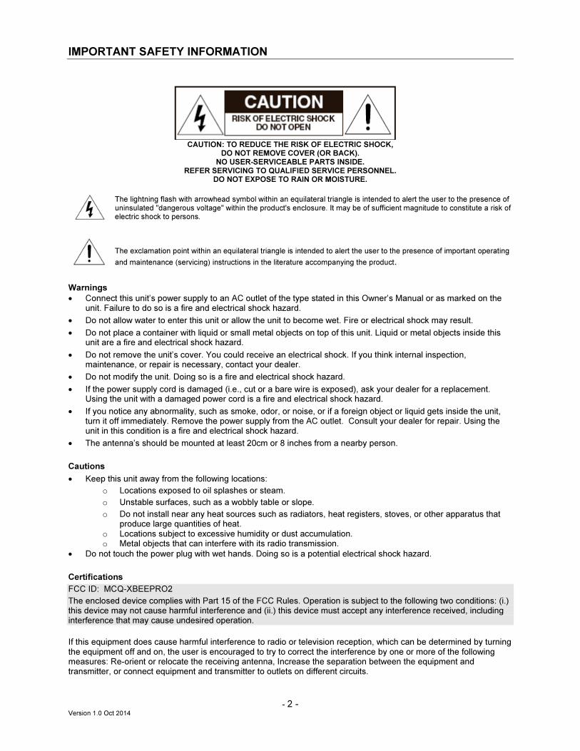
CAUTION: TO REDUCE THE RISK OF ELECTRIC SHOCK,
DO NOT REMOVE COVER (OR BACK). NO USER-SERVICEABLE PARTS INSIDE.
REFER SERVICING TO QUALIFIED SERVICE PERSONNEL. DO NOT EXPOSE TO RAIN OR MOISTURE.
The lightning flash with arrowhead symbol within an equilateral triangle is intended to alert the user to the presence of uninsulated "dangerous voltage" within the product's enclosure. It may be of sufficient magnitude to constitute a risk of electric shock to persons.
The exclamation point within an equilateral triangle is intended to alert the user to the presence of important operating
and maintenance (servicing) instructions in the literature accompanying the product.
Warnings
• Connect this unit’s power supply to an AC outlet of the type stated in this Owner’s Manual or as marked on the unit. Failure to do so is a fire and electrical shock hazard.
• Do not allow water to enter this unit or allow the unit to become wet. Fire or electrical shock may result.
• Do not place a container with liquid or small metal objects on top of this unit. Liquid or metal objects inside this unit are a fire and electrical shock hazard.
• Do not remove the unit’s cover. You could receive an electrical shock. If you think internal inspection, maintenance, or repair is necessary, contact your dealer.
• Do not modify the unit. Doing so is a fire and electrical shock hazard.
• If the power supply cord is damaged (i.e., cut or a bare wire is exposed), ask your dealer for a replacement. Using the unit with a damaged power cord is a fire and electrical shock hazard.
• If you notice any abnormality, such as smoke, odor, or noise, or if a foreign object or liquid gets inside the unit, turn it off immediately. Remove the power supply from the AC outlet. Consult your dealer for repair. Using the unit in this condition is a fire and electrical shock hazard.
• The antenna’s should be mounted at least 20cm or 8 inches from a nearby person.
Cautions
• Keep this unit away from the following locations:
o Locations exposed to oil splashes or steam.
o Unstable surfaces, such as a wobbly table or slope.
o Do not install near any heat sources such as radiators, heat registers, stoves, or other apparatus that produce large quantities of heat.
o Locations subject to excessive humidity or dust accumulation. o Metal objects that can interfere with its radio transmission.
• Do not touch the power plug with wet hands. Doing so is a potential electrical shock hazard.
Certifications
FCC ID: MCQ-XBEEPRO2
The enclosed device complies with Part 15 of the FCC Rules. Operation is subject to the following two conditions: (i.) this device may not cause harmful interference and (ii.) this device must accept any interference received, including interference that may cause undesired operation.
If this equipment does cause harmful interference to radio or television reception, which can be determined by turning the equipment off and on, the user is encouraged to try to correct the interference by one or more of the following measures: Re-orient or relocate the receiving antenna, Increase the separation between the equipment and transmitter, or connect equipment and transmitter to outlets on different circuits.

- 3 - Version 1.0 Oct 2014
INTRODUCTION
Thank you for choosing a Sound Associates, Inc. manufactured product. All Sound Associates, Inc. products are carefully designed and engineered for cutting edge performance and world class reliability. I-Caption® is a state-of-the-art, wireless visual aid that provides verbatim closed captions and subtitling on an individual hand-held receiver. Originally designed for live theatrical productions, this fully-automated system displays dialogue, lyrics and sound effects with the efficiency of real-time captioning at a fraction of the cost. The R4 wireless video display is a state-of-the-art receiver capable of supplying verbatim closed captions, subtitles, graphics or audio playback on an individual hand-held receiver. Originally designed for live theatrical productions, this fully-automated system conveys pre-programmed dialogue, lyrics and sound effects with the efficiency of real-time captioning at a fraction of the cost and manpower. Each R4 receiver is a self-contained, non-intrusive wireless unit that can be used in any seat in the venue, allowing patrons with special needs to become active members of the general audience, no longer limited to certain performances or relegated to special seating constraints. The R4, when coupled with the T4 transmitter and the CS-3 control unit, will display I-Caption user defined slides for closed captions or subtitling. The R4 can also playback prerecorded audio files in mp3 format for audio description for the blind or for multi-lingual audio commentary. When used with the I-Caption computer base station, it is the key component to a completely automated display system, utilizing proprietary wireless technology to deliver reliable cue changes every time.
FEATURES
• High resolution color TFT LCD display supplies crisp graphics and text that is easy see at all angles.
• 3.5” LCD display allows a comfortable amount of dialogue on the screen at one time.
• Backlight can be ramped on or down from 0% to 100% over a specified period of time for each individual slide allowing the natural transition from dark to light.
• Each unit has been ergonomically designed to fit comfortably in the patron's hand with little or no long–term fatigue.
• Completely self-contained, battery powered, receiving show information via an innovative 2.4 GHz mesh network, specifically designed to work in high traffic radio transmission areas.
• Completely automated delivery of audio and video segments when coupled with the I-Caption CS-3 control unit.
UNPACKING UNIT
As soon as the shipment is received, inspect the unit and all components for damage incurred by shipping. Also, check to see if all components are enclosed. Equipment enclosed: 1 R4 Receiver with wrist strap 1 3.7V Lithium Ion rechargeable battery (pre-installed in receiver) 1 Micro SD card (pre-installed in receiver)
1 USB A to USB mini-B charging adapter cable 1 Instruction manual
If the unit is damaged due to shipping, please keep all packing material and contact the shipping company as soon as possible. Only the consignee may institute a claim against a carrier if damage has occurred in shipping; however, Sound Associates will assist in any such event.
FRONT PANEL CONTROLS
1 – Left/Back Arrow: Decreases volume (when audio is playing); moves back up to two slides when I-Caption is running; down arrow in menu modes.

- 4 - Version 1.0 Oct 2014
2 – Center Button: Shows battery and signal strength while in regular operating mode; enter button in menu modes. 3 – Right/Forward Arrow: Increases volume (when audio is playing); returns to current slide when I-Caption is running; up arrow in menu modes. .Note: The R4 control buttons have different functions depending on which mode the receiver is operating in.
SIDE PANEL CONNECTIONS
4 – USB Connector: Connects USB for charging or data transfer. 5 – Power Switch: Toggle switch to turn unit on or off; recessed to prevent accidental powering off.
6 – Audio Jack: 1/8” mini jack; works with mono or stereo. 7 – Power Indicator LED: Solid LED indicates unit is charging; Solid with recessed flashing LED indicates unit is operational. Note: Flashing light is more recessed (and to the side of the solid LED) to reduce distractions to others.
8 – Micro SD Card Slot: Show configuration and content are
stored on micro SD cards.
INSTALLATION OF SD CARD CONFIGURATOR
Prior to installation of the first “show”, the SD Card Configurator Program, must be installed. This program assists in setting up the structure and parameters for each show or service(s) as well as allowing a user to load a card with the video and/or audio files to be displayed or played on the R4 receiver. The SD Card Configurator will also convert captions created in Power Point to jpegs for use on the R4 Receiver. Please follow the directions below to install and use the program. If you need assistance please contact Sound Associates, Inc. at 888-772-SOUND (7686).
Install Program on CS3/CS3L or other Windows-based computer (XP Service Pack 2 or greater).
• Uninstall any earlier versions of the SD Card Configurator Program that resides on the computer that the installation is being performed.
• PC must run Windows XP SP2 or higher with the latest .NET frame updates.
• Insert disk and select R-4 SD Card Configurator v2._.exe to run.
• Once installed it will create a desk top icon.
- 5 - Version 1.0 Oct 2014
ADDING A NEW SHOW – R4 INITIAL SET UP
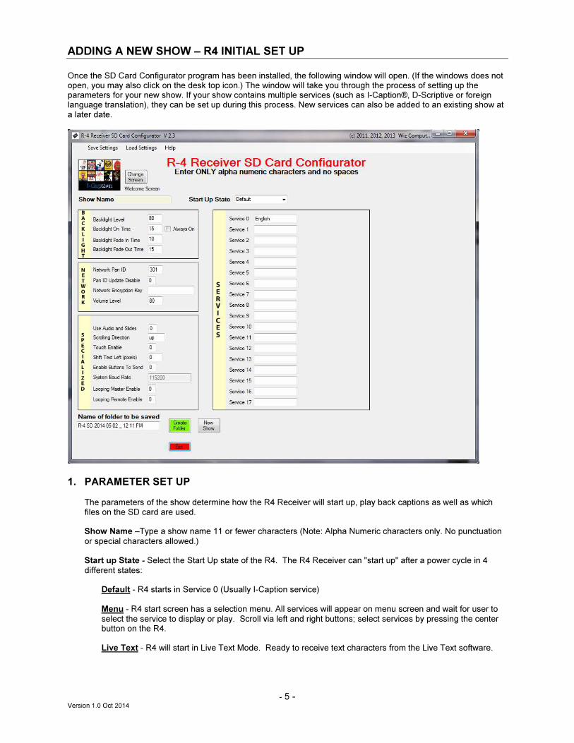
Once the SD Card Configurator program has been installed, the following window will open. (If the windows does not open, you may also click on the desk top icon.) The window will take you through the process of setting up the parameters for your new show. If your show contains multiple services (such as I-Caption®, D-Scriptive or foreign language translation), they can be set up during this process. New services can also be added to an existing show at a later date.
1. PARAMETER SET UP
The parameters of the show determine how the R4 Receiver will start up, play back captions as well as which
files on the SD card are used.
Show Name –Type a show name 11 or fewer characters (Note: Alpha Numeric characters only. No punctuation or special characters allowed.) Start up State - Select the Start Up state of the R4. The R4 Receiver can "start up" after a power cycle in 4 different states:
Default - R4 starts in Service 0 (Usually I-Caption service)
Menu - R4 start screen has a selection menu. All services will appear on menu screen and wait for user to select the service to display or play. Scroll via left and right buttons; select services by pressing the center button on the R4. Live Text - R4 will start in Live Text Mode. Ready to receive text characters from the Live Text software.
- 6 - Version 1.0 Oct 2014
Save Selection - R4 will start in Menu mode during the first power cycle. Once the selection is made it will save that selection and start in that selected service when the unit is power cycled. To return to the Menu page hold the left hand side arrow button and power cycle the R4 unit. Again that selection made will be saved until a new selection is made from the Menu page.
Example of Use: If the service is selected for audio description and the unit is handed to a sight impaired patron. If he or she shuts the unit off it will return to the selected service automatically. No menu selection is needed.
Change Welcome Screen – Please select the jpg file that you would like to display on the units at start up. Services – Add all the services you wish to create. For example “ICaption” (for English Captions slides), “DScriptive” (Audio Description audio files), “French” (French commentary audio files), etc. Service name must be 11 or fewer characters (Note: Alpha Numeric characters only. No punctuation or special characters allowed.) Backlight - Change any Backlight Parameters you wish. Level 0-99, slide to stay on time in seconds, etc.
2. CREATING FILE FOLDER LOCATION
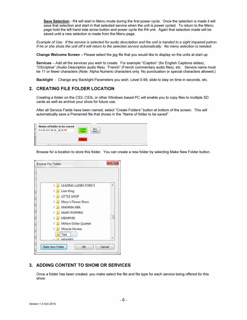
Creating a folder on the CS3, CS3L or other Windows based PC will enable you to copy files to multiple SD cards as well as archive your show for future use. After all Service Fields have been named, select “Create Folders" button at bottom of the screen. This will automatically save a Prenamed file that shows in the “Name of folder to be saved”
Browse for a location to store this folder. You can create a new folder by selecting Make New Folder button.
3. ADDING CONTENT TO SHOW OR SERVICES
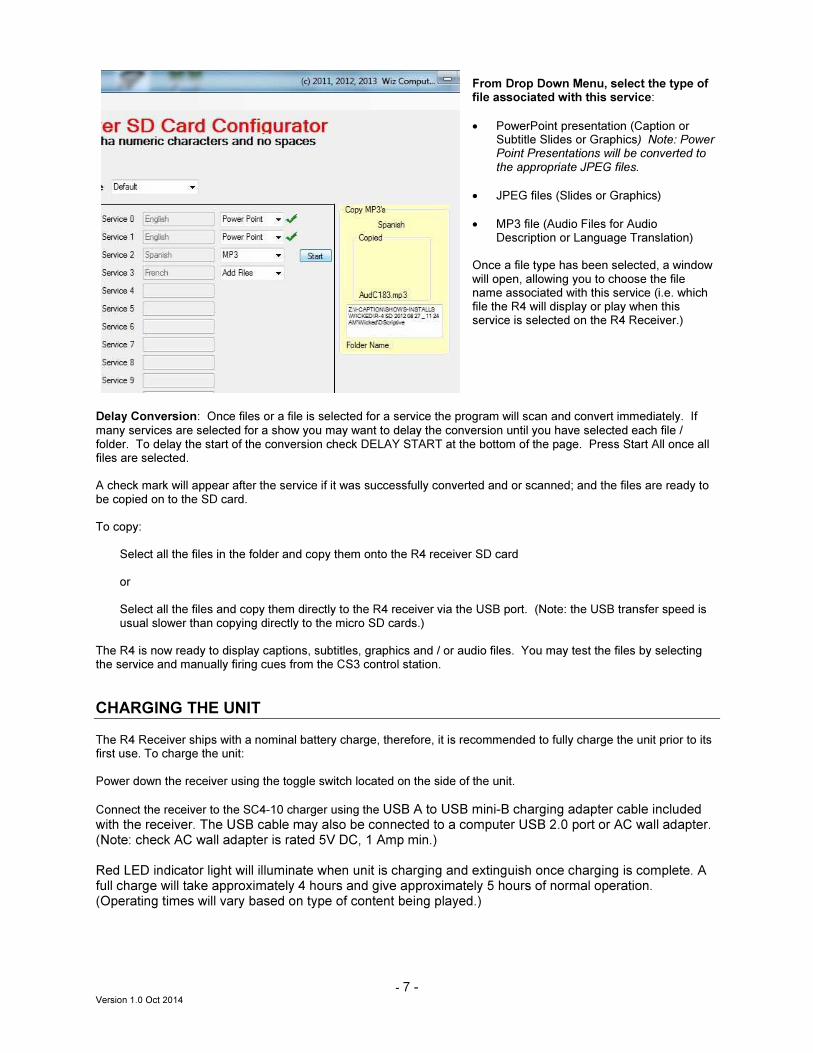
Once a folder has been created, you make select the file and file type for each service being offered for this show.
- 7 - Version 1.0 Oct 2014
From Drop Down Menu, select the type of file associated with this service:
• PowerPoint presentation (Caption or Subtitle Slides or Graphics) Note: Power Point Presentations will be converted to the appropriate JPEG files.
• JPEG files (Slides or Graphics)
• MP3 file (Audio Files for Audio Description or Language Translation)
Once a file type has been selected, a window will open, allowing you to choose the file name associated with this service (i.e. which file the R4 will display or play when this service is selected on the R4 Receiver.)
Delay Conversion: Once files or a file is selected for a service the program will scan and convert immediately. If many services are selected for a show you may want to delay the conversion until you have selected each file / folder. To delay the start of the conversion check DELAY START at the bottom of the page. Press Start All once all files are selected. A check mark will appear after the service if it was successfully converted and or scanned; and the files are ready to be copied on to the SD card. To copy:
Select all the files in the folder and copy them onto the R4 receiver SD card or Select all the files and copy them directly to the R4 receiver via the USB port. (Note: the USB transfer speed is usual slower than copying directly to the micro SD cards.)
The R4 is now ready to display captions, subtitles, graphics and / or audio files. You may test the files by selecting the service and manually firing cues from the CS3 control station.
CHARGING THE UNIT
The R4 Receiver ships with a nominal battery charge, therefore, it is recommended to fully charge the unit prior to its first use. To charge the unit: Power down the receiver using the toggle switch located on the side of the unit.
Connect the receiver to the SC4-10 charger using the USB A to USB mini-B charging adapter cable included with the receiver. The USB cable may also be connected to a computer USB 2.0 port or AC wall adapter. (Note: check AC wall adapter is rated 5V DC, 1 Amp min.) Red LED indicator light will illuminate when unit is charging and extinguish once charging is complete. A full charge will take approximately 4 hours and give approximately 5 hours of normal operation. (Operating times will vary based on type of content being played.)
- 8 - Version 1.0 Oct 2014
RUNNING A SERVICE – OPERATION OF R4 RECEIVER
To operate the R4 Receiver, first insert an SD card that has been formatted through the SD Card Configurator. (See page 6.) Once the card is inserted, use the toggle switch on the side of the unit to power on. The “start up” mode of the unit is predetermined by “Start Up State” chosen during the SD card configuration and is specific to the configuration of the card currently installed. Default Mode: Automatically chooses Service 0 as the default service
• Welcome Screen is displayed
• Unit is ready for operation Menu Mode: Displays a list of services available (including default and Live Text, if offered.)
• Menu list is displayed
• Use left arrow to scroll down list (right arrow to scroll up)
• Use center button to select service
• Screen displays confirmation of selection
• Welcome Screen is displayed
• Unit is ready for operation Save Selection Mode: Allows units to be assigned their own unique default start up service (keyed to the SD card)
• Menu list is displayed
• Use left arrow to scroll down list (right arrow to scroll up)
• Use center button to select service
• Screen displays confirmation of selection and saves as default service for future.
• Welcome Screen is displayed
• Unit is ready for operation
• To change default selection, press �button while powering unit on. When the menu screen appears,
choose new service for the default (for this receiver) and choose enter. This service will now be the default the next time the unit is powered on (except Live Text).
Live Text Mode: Text manually entered
• Welcome Screen is displayed
• Unit is ready for operation.
• The R4 Receiver can also boot up in Live Text by holding the center button while powering the unit on. Hold the button until the Welcome Screen is replaced with “Live Text” at the bottom of the screen. The Welcome Screen will return until the first Live Text is sent.
Demo Mode: Allows the R4 to display a show by manually moving through each cue
• To enter Demo Mode, power the unit on while holding both the�and�buttons on front of the receiver until
the words “Demo Mode” appear at the bottom of the display.
• Unit will search for content stored in the “Demo” Folder on the SD card.
• Press the button to advance to the first slide or audio file in the demo
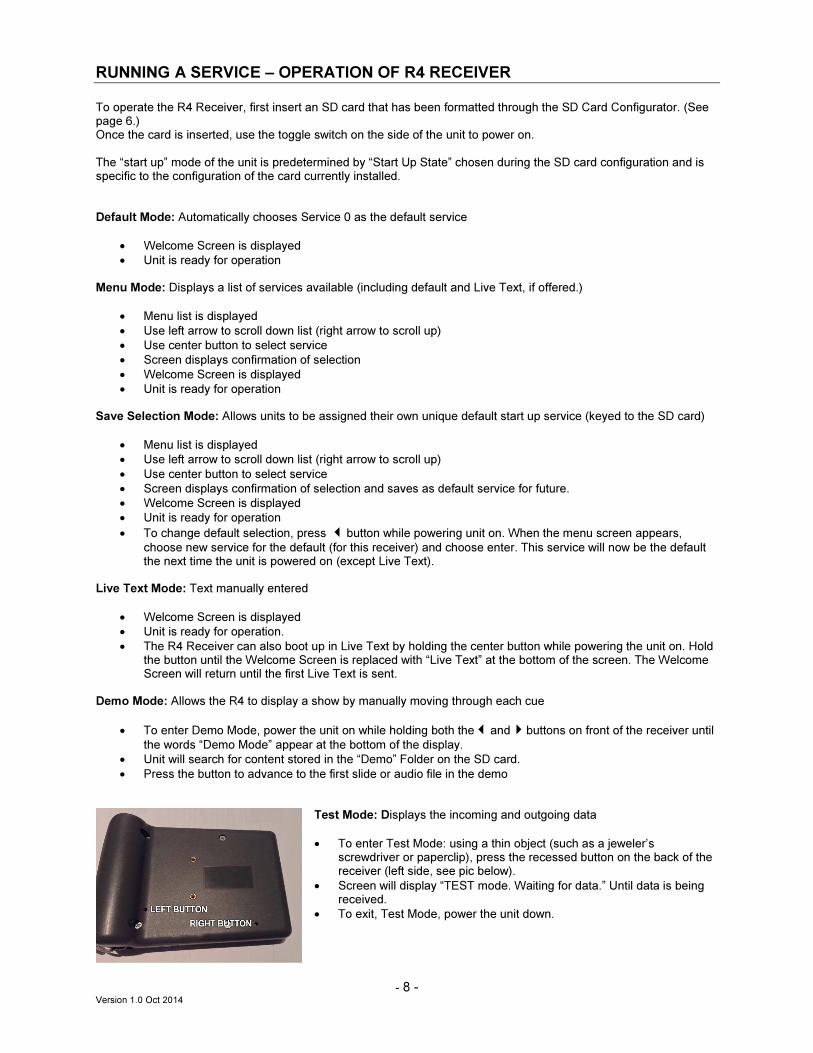
Test Mode: Displays the incoming and outgoing data
• To enter Test Mode: using a thin object (such as a jeweler’s screwdriver or paperclip), press the recessed button on the back of the receiver (left side, see pic below).
• Screen will display “TEST mode. Waiting for data.” Until data is being received.
• To exit, Test Mode, power the unit down.
- 9 - Version 1.0 Oct 2014
Info Screen: displays systems settings created by the SD Card Configuator for the SD card currently in use.
• To display Info Screen: using a thin object (such as a jeweler’s screwdriver or paperclip), press the recessed button on the back of the receiver (right side, see pic above) .
• Systems Settings are displayed.
• To exit, press the� button. (Note: screen will also disappear when next cue is displayed.)
THEORY OF OPERATION
The primary T4 transmitter / coordinator is hardwired to the CS-3 control unit and broadcasts cue information to the receivers via a wireless mesh network in the 2.4 GHz range. Additional, T4 repeaters can be added to the network to increase coverage. Repeaters can be either wireless or hardwired with CAT5E cable terminated in an EtherCon connector. Voltage is supplied to the T4 via the CAT5E cable for cable runs under 150 ft, otherwise local 5-7 VDC is required. The T4 Coordinator and T4R Repeater unit incorporates a sensitive RF transceiver utilizing a peer-to-peer protocol in 2.4 GHz range for operation in global markets. This innovative mesh protocol offers added network stability through self-healing, self-discovery, and dense network operation.
STANDARD DESIGNS AND INSTALLATIONS
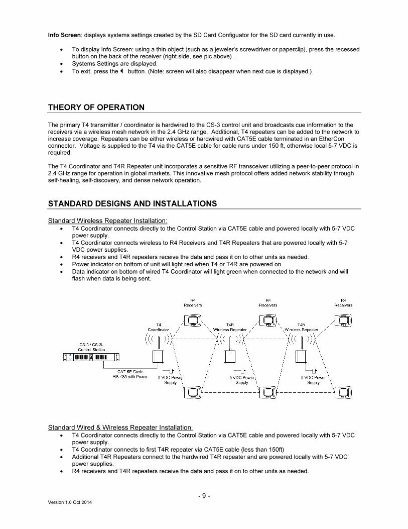
Standard Wireless Repeater Installation:
• T4 Coordinator connects directly to the Control Station via CAT5E cable and powered locally with 5-7 VDC power supply.
• T4 Coordinator connects wireless to R4 Receivers and T4R Repeaters that are powered locally with 5-7 VDC power supplies.
• R4 receivers and T4R repeaters receive the data and pass it on to other units as needed.
• Power indicator on bottom of unit will light red when T4 or T4R are powered on.
• Data indicator on bottom of wired T4 Coordinator will light green when connected to the network and will flash when data is being sent.
Standard Wired & Wireless Repeater Installation:
• T4 Coordinator connects directly to the Control Station via CAT5E cable and powered locally with 5-7 VDC power supply.
• T4 Coordinator connects to first T4R repeater via CAT5E cable (less than 150ft)
• Additional T4R Repeaters connect to the hardwired T4R repeater and are powered locally with 5-7 VDC power supplies.
• R4 receivers and T4R repeaters receive the data and pass it on to other units as needed.
- 10 - Version 1.0 Oct 2014
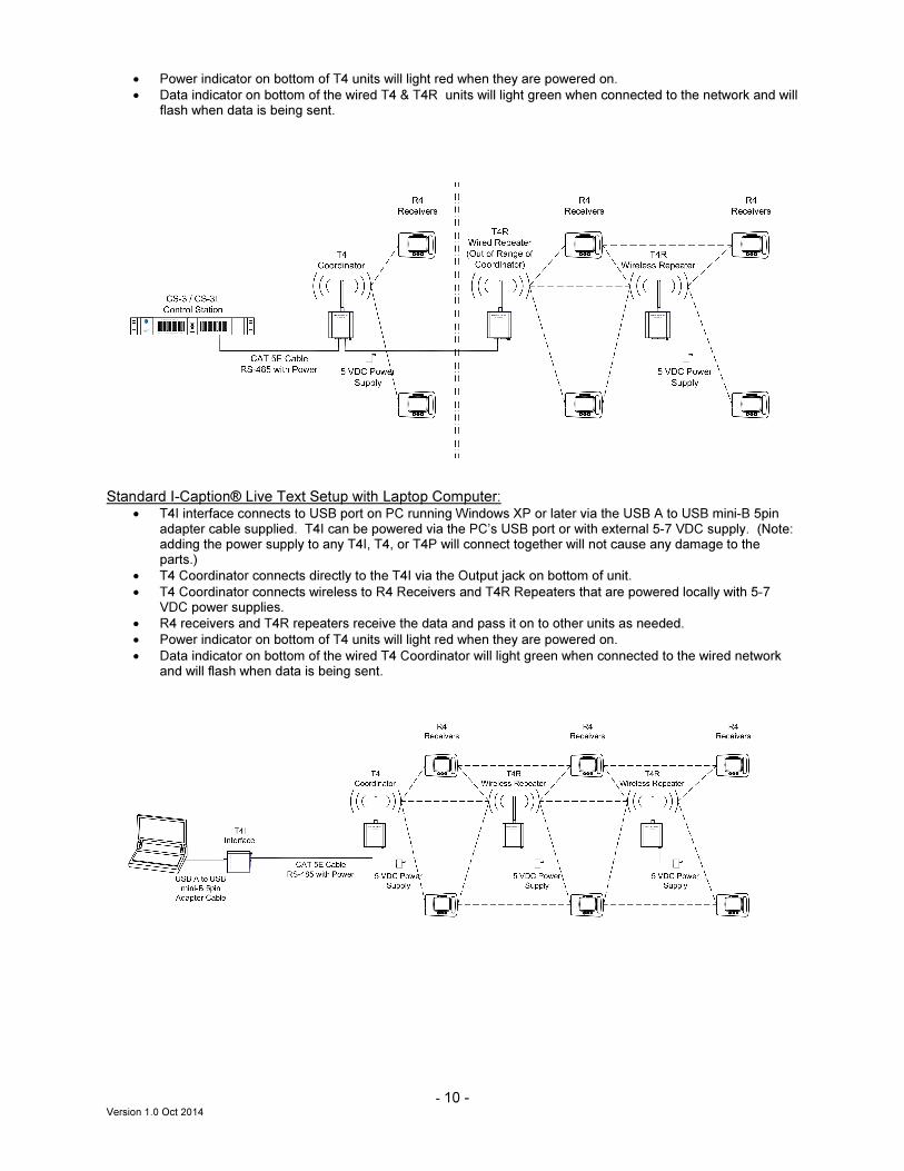
• Power indicator on bottom of T4 units will light red when they are powered on.
• Data indicator on bottom of the wired T4 & T4R units will light green when connected to the network and will flash when data is being sent.
Standard I-Caption® Live Text Setup with Laptop Computer:
• T4I interface connects to USB port on PC running Windows XP or later via the USB A to USB mini-B 5pin adapter cable supplied. T4I can be powered via the PC’s USB port or with external 5-7 VDC supply. (Note: adding the power supply to any T4I, T4, or T4P will connect together will not cause any damage to the parts.)
• T4 Coordinator connects directly to the T4I via the Output jack on bottom of unit.
• T4 Coordinator connects wireless to R4 Receivers and T4R Repeaters that are powered locally with 5-7 VDC power supplies.
• R4 receivers and T4R repeaters receive the data and pass it on to other units as needed.
• Power indicator on bottom of T4 units will light red when they are powered on.
• Data indicator on bottom of the wired T4 Coordinator will light green when connected to the wired network and will flash when data is being sent.
- 11 - Version 1.0 Oct 2014
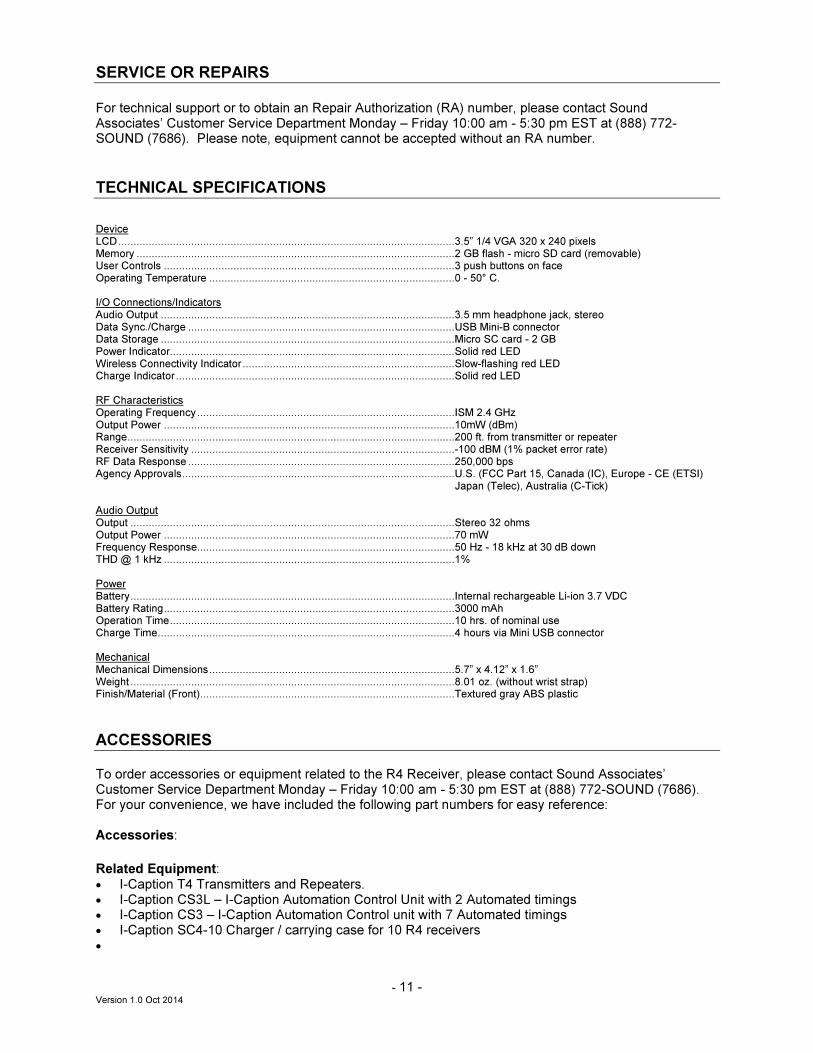
SERVICE OR REPAIRS
For technical support or to obtain an Repair Authorization (RA) number, please contact Sound Associates’ Customer Service Department Monday – Friday 10:00 am - 5:30 pm EST at (888) 772-SOUND (7686). Please note, equipment cannot be accepted without an RA number.
TECHNICAL SPECIFICATIONS
Device LCD...............................................................................................................3.5” 1/4 VGA 320 x 240 pixels Memory .........................................................................................................2 GB flash - micro SD card (removable) User Controls ................................................................................................3 push buttons on face Operating Temperature .................................................................................0 - 50° C. I/O Connections/Indicators Audio Output .................................................................................................3.5 mm headphone jack, stereo Data Sync./Charge ........................................................................................USB Mini-B connector Data Storage .................................................................................................Micro SC card - 2 GB Power Indicator..............................................................................................Solid red LED Wireless Connectivity Indicator ......................................................................Slow-flashing red LED Charge Indicator ............................................................................................Solid red LED RF Characteristics Operating Frequency .....................................................................................ISM 2.4 GHz Output Power ................................................................................................10mW (dBm) Range............................................................................................................200 ft. from transmitter or repeater Receiver Sensitivity .......................................................................................-100 dBM (1% packet error rate) RF Data Response ........................................................................................250,000 bps Agency Approvals..........................................................................................U.S. (FCC Part 15, Canada (IC), Europe - CE (ETSI) Japan (Telec), Australia (C-Tick) Audio Output Output ...........................................................................................................Stereo 32 ohms Output Power ................................................................................................70 mW Frequency Response.....................................................................................50 Hz - 18 kHz at 30 dB down THD @ 1 kHz ................................................................................................1% Power Battery...........................................................................................................Internal rechargeable Li-ion 3.7 VDC Battery Rating................................................................................................3000 mAh Operation Time..............................................................................................10 hrs. of nominal use Charge Time..................................................................................................4 hours via Mini USB connector Mechanical Mechanical Dimensions.................................................................................5.7” x 4.12” x 1.6” Weight ...........................................................................................................8.01 oz. (without wrist strap) Finish/Material (Front)....................................................................................Textured gray ABS plastic
ACCESSORIES
To order accessories or equipment related to the R4 Receiver, please contact Sound Associates’ Customer Service Department Monday – Friday 10:00 am - 5:30 pm EST at (888) 772-SOUND (7686). For your convenience, we have included the following part numbers for easy reference: Accessories:
Related Equipment: • I-Caption T4 Transmitters and Repeaters. • I-Caption CS3L – I-Caption Automation Control Unit with 2 Automated timings • I-Caption CS3 – I-Caption Automation Control unit with 7 Automated timings • I-Caption SC4-10 Charger / carrying case for 10 R4 receivers •
- 12 - Version 1.0 Oct 2014
SOUND ASSOCIATES
FULL THREE YEAR WARRANTY
We, Sound Associates, Inc., warrant to you the original owner or any
subsequent owner of each new Sound Associates infrared transmitter, emitter
power supply, or emitter panel, that the unit is free of defects in workmanship and
materials for a period of three years from date of original purchase. If the infrared
product fails due to defects in materials or workmanship, or does not meet
specifications enclosed with the product, Sound Associates will repair or replace
the unit, whichever Sound Associates chooses, free of charge. All repairs will be
conducted by trained personnel at Sound Associates’ facility in reasonable time.
All expenses on remedying the defect, including return shipping will be borne by
Sound Associates. All shipping fees, taxes, duties, and other customs fees
incurred by products being shipped between foreign countries will be borne by
the purchaser.
Sound Associates is not responsible for malfunctions due to misuse,
accident, or neglect. This warranty does not cover damage to other products
resulting from Sound Associates product failure. It does not cover defects or
damage caused by unauthorized modifications or service. Sound Associates
reserves the right to change the design of any product without notice and with no
obligation to make corresponding changes in products previously manufactured.