operation manual - quantum opus · pdf fileoperation manual sumitomo heavy industries, ltd....
TRANSCRIPT
MANUAL NUMBER: CD32ZZ-063IDATE: December 18 / 2003
OPERATION MANUALSRDK Series CRYOCOOLER
For Service Personnel Only
Sumitomo Heavy Industries, Ltd.Cryogenics Division
2-1-1 Yato-cho, Nishitokyo-City,Tokyo 188-8585, Japan
TEL: +81-424-68-4240FAX: +81-424-68-4219E-mail: [email protected]
URL: http://www.shi.co.jp/cryopage
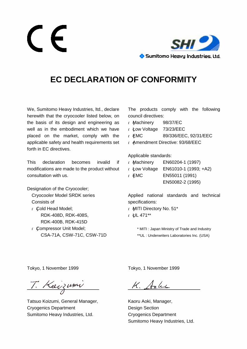
EC DECLARATION OF CONFORMITY
We, Sumitomo Heavy Industries, ltd., declare
herewith that the cryocooler listed below, on
the basis of its design and engineering as
well as in the embodiment which we have
placed on the market, comply with the
applicable safety and health requirements set
forth in EC directives.
This declaration becomes invalid if
modifications are made to the product without
consultation with us.
Designation of the Cryocooler;
Cryocooler Model SRDK series
Consists of
・ Cold Head Model;
RDK-408D, RDK-408S,
RDK-400B, RDK-415D
・ Compressor Unit Model;
CSA-71A, CSW-71C, CSW-71D
Tokyo, 1 November 1999
Tatsuo Koizumi, General Manager,
Cryogenics Department
Sumitomo Heavy Industries, Ltd.
The products comply with the following
council directives:
・ Machinery 98/37/EC
・ Low Voltage 73/23/EEC
・ EMC 89/336/EEC, 92/31/EEC
・ Amendment Directive: 93/68/EEC
Applicable standards:
・ Machinery EN60204-1 (1997)
・ Low Voltage EN61010-1 (1993; +A2)
・ EMC EN55011 (1991)
EN50082-2 (1995)
Applied national standards and technical
specifications:
・ MITI Directory No. 51*
・ UL 471**
* MITI : Japan Ministry of Trade and Industry
**UL : Underwriters Laboratories Inc. (USA)
Tokyo, 1 November 1999
Kaoru Aoki, Manager,
Design Section
Cryogenics Department
Sumitomo Heavy Industries, Ltd.
OPERATION MANUAL Sumitomo Heavy Industries, Ltd.
SRDK Series CRYOCOOLER
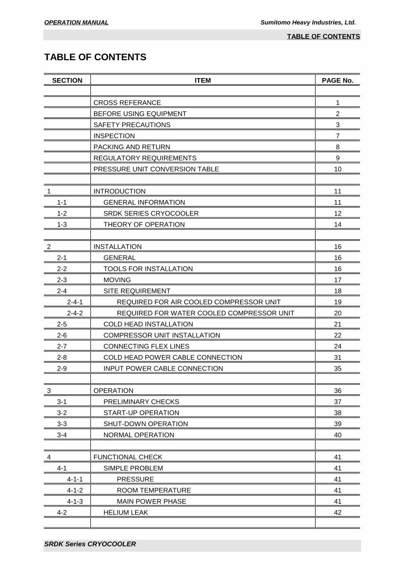
TABLE OF CONTENTS
TABLE OF CONTENTS
SECTION ITEM PAGE No.
CROSS REFERANCE 1
BEFORE USING EQUIPMENT 2
SAFETY PRECAUTIONS 3
INSPECTION 7
PACKING AND RETURN 8
REGULATORY REQUIREMENTS 9
PRESSURE UNIT CONVERSION TABLE 10
1 INTRODUCTION 11
1-1 GENERAL INFORMATION 11
1-2 SRDK SERIES CRYOCOOLER 12
1-3 THEORY OF OPERATION 14
2 INSTALLATION 16
2-1 GENERAL 16
2-2 TOOLS FOR INSTALLATION 16
2-3 MOVING 17
2-4 SITE REQUIREMENT 18
2-4-1 REQUIRED FOR AIR COOLED COMPRESSOR UNIT 19
2-4-2 REQUIRED FOR WATER COOLED COMPRESSOR UNIT 20
2-5 COLD HEAD INSTALLATION 21
2-6 COMPRESSOR UNIT INSTALLATION 22
2-7 CONNECTING FLEX LINES 24
2-8 COLD HEAD POWER CABLE CONNECTION 31
2-9 INPUT POWER CABLE CONNECTION 35
3 OPERATION 36
3-1 PRELIMINARY CHECKS 37
3-2 START-UP OPERATION 38
3-3 SHUT-DOWN OPERATION 39
3-4 NORMAL OPERATION 40
4 FUNCTIONAL CHECK 41
4-1 SIMPLE PROBLEM 41
4-1-1 PRESSURE 41
4-1-2 ROOM TEMPERATURE 41
4-1-3 MAIN POWER PHASE 41
4-2 HELIUM LEAK 42

OPERATION MANUAL Sumitomo Heavy Industries, Ltd.
SRDK Series CRYOCOOLER
TABLE OF CONTENTS
5 MAINTENANCE 43
5-1 GENERAL INFORMATION FOR THE MAINTENANCE 44
5-2 COLD HEAD MAINTENANCE 45
5-3 COMPRESSOR UNIT MAINTENANCE 45
5-4 HELIUM GAS CHARGING 46
6 TROUBLE SHOOTING FLOW CHART 48
7 OPERATING LOG 55
REVISION CONTROL

OPERATION MANUAL Sumitomo Heavy Industries, Ltd.
SRDK Series CRYOCOOLER 1
CROSS REFERENCE
CROSS REFERENCE
Thoroughly read this manual and following manuals before using this equipment.
MANUAL NAME MANUAL No. TECHNICAL INSTRUCTION RDK-408D2 4K COLD HEAD* CD32ZZ-160
TECHNICAL INSTRUCTION RDK-408D 4K COLD HEAD* CD32ZZ-064
TECHNICAL INSTRUCTION RDK-408S2 10K COLD HEAD* CD32ZZ-161
TECHNICAL INSTRUCTION RDK-408S 10K COLD HEAD* CD32ZZ-065
TECHNICAL INSTRUCTION RDK-400B SINGLE STAGE COLD HEAD* CD32ZZ-066
TECHNICAL INSTRUCTION RDK-415D 4K COLD HEAD* CD32ZZ-070
TECHNICAL INSTRUCTION CSA-71A COMPRESSOR UNIT** CD32ZZ-067
TECHNICAL INSTRUCTION CSW-71C COMPRESSOR UNIT** CD32ZZ-068
TECHNICAL INSTRUCTION CSW-71D COMPRESSOR UNIT** CD32ZZ-069
* See TECHNICAL INSTRUCTION of Cold Head used.
** See TECHNICAL INSTRUCTION of Compressor Unit used.

OPERATION MANUAL Sumitomo Heavy Industries, Ltd.
SRDK Series CRYOCOOLER 2
BEFORE USING EQUIPMENT
BEFORE USING EQUIPMENT
・ This service manual is intended only for the exclusive service personnel.
・ Sumitomo Heavy Industries will not be responsible for any accidents, failures, non-conformities, etc.
caused by operations by any persons other than service personnel according to the descriptions in this
manual.
・ This service manual describes important information such as the installation method, operation method
and maintenance of this equipment.
・ Be sure to read this service manual before using this cryocooler.
・ Using the equipment without observing the descriptions in this manual may result in malfunction of the
equipment or may be hazardous to the physical body of the operator. Sumitomo Heavy Industries will
provide no guarantee in this case.
・ No part of this manual may be reproduced without the consent of Sumitomo Heavy Industries, Ltd. The
use of this manual for other purposes is prohibited.
OPERATION MANUAL Sumitomo Heavy Industries, Ltd.
SRDK Series CRYOCOOLER 3
SAFETY PRECAUTIONS
SAFETY PRECAUTIONS
This service manual uses the following signs and expressions to describe items requiring strict observance
to prevent injury to the operator and other persons, damage to this equipment, the customer's equipment
and property, etc.
“WARNING”Indicates a potentially hazardous situation that may cause injury to the operator or
people around the equipment in the event of improper handling taking no account of
this description.
When using this equipment, be sure to adhere to this description.
“CAUTION”Indicates a potentially hazardous situation that may result in misoperation, malfunction,
or damage of the customer's equipment, etc. in the event of improper handling taking
no account of this description.
When using this equipment, be sure to adhere to this description.
WARNING
CAUTION
OPERATION MANUAL Sumitomo Heavy Industries, Ltd.
SRDK Series CRYOCOOLER 4
SAFETY PRECAUTIONS
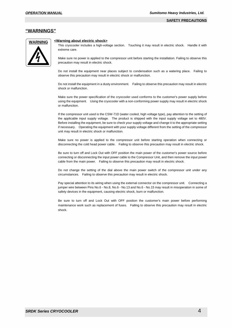
“WARNINGS”
<Warning about electric shock>This cryocooler includes a high-voltage section. Touching it may result in electric shock. Handle it with
extreme care.
Make sure no power is applied to the compressor unit before starting the installation. Failing to observe this
precaution may result in electric shock.
Do not install the equipment near places subject to condensation such as a watering place. Failing to
observe this precaution may result in electric shock or malfunction.
Do not install the equipment in a dusty environment. Failing to observe this precaution may result in electric
shock or malfunction.
Make sure the power specification of the cryocooler used conforms to the customer's power supply before
using the equipment. Using the cryocooler with a non-conforming power supply may result in electric shock
or malfunction.
If the compressor unit used is the CSW-71D (water cooled, high voltage type), pay attention to the setting of
the applicable input supply voltage. The product is shipped with the input supply voltage set to 480V.
Before installing the equipment, be sure to check your supply voltage and change it to the appropriate setting
if necessary. Operating the equipment with your supply voltage different from the setting of the compressor
unit may result in electric shock or malfunction.
Make sure no power is applied to the compressor unit before starting operation when connecting or
disconnecting the cold head power cable. Failing to observe this precaution may result in electric shock.
Be sure to turn off and Lock Out with OFF position the main power of the customer's power source before
connecting or disconnecting the input power cable to the Compressor Unit, and then remove the input power
cable from the main power. Failing to observe this precaution may result in electric shock.
Do not change the setting of the dial above the main power switch of the compressor unit under any
circumstances. Failing to observe this precaution may result in electric shock.
Pay special attention to its wiring when using the external connector on the compressor unit. Connecting a
jumper wire between Pins No.6 - No.8, No.6 - No.13 and No.6 - No.15 may result in misoperation in some of
safety devices in the equipment, causing electric shock, burn or malfunction.
Be sure to turn off and Lock Out with OFF position the customer's main power before performing
maintenance work such as replacement of fuses. Failing to observe this precaution may result in electric
shock.
WARNING

OPERATION MANUAL Sumitomo Heavy Industries, Ltd.
SRDK Series CRYOCOOLER 5
SAFETY PRECAUTIONS
<Warning about explosion, escape of gas>This cryocooler (cold head, compressor unit, compressor adsorber, flex lines) contains a high-pressure
(about 1.62 MPa (16.5 kgf/cm2G, 235 psig)) helium gas sealed in. Hitting the equipment with a sharp edge
or touching it with a pointed object may cause explosion or escape of gas. Handle the equipment with
extreme care.
The minimum bending radius of the flex lines is 300 mm (11. 81 inches). Bending the flex lines at a smaller
angle may cause explosion or escape of gas, and so this should be avoided.
Do not disassemble the equipment for purposes other than maintenance specified in this service manual
under any circumstances. Disassembling the equipment may result in electric shock, explosion or escape
of gas.
The cold head, compressor unit, compressor adsorber and flex lines are pressurized with helium gas.
Purge the helium gas from all pressurized components before disposing. Open the purging valve gradually
or it may result in serious injury.
Do not break the vacuum with the low temperature of cold head second stage when removing the cold head
from the vacuum chamber. Breaking the vacuum may result in serious damage, explosion or escape of
gas. Keep the Flex Lines connected and maintain the high vacuum of the chamber and wait until the cold
head second stage temperature rises up to 100K before removing the cold head.
<Warning about rotating part>If the compressor unit used is the CSA-71A (air cooled, low voltage type), a venting fan is provided in the
exhaust section at the top of the compressor unit. Do not insert foreign substances from the exhaust port
under any circumstances. Failing to observe this precaution may result in injury or malfunction.
Do not touch the cooler fin of the Compressor Unit during fin cleaning. Touching the fin may cause the injury.
The Adsorber weight is about 11.0kg. When replace the adsorber, be careful of handling so that it may not get
hurt.
WARNING
WARNING
WARNING
OPERATION MANUAL Sumitomo Heavy Industries, Ltd.
SRDK Series CRYOCOOLER 6
SAFETY PRECAUTIONS
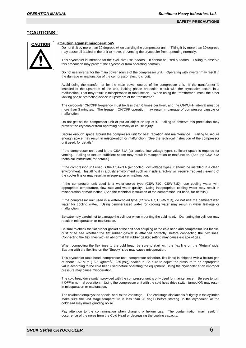
“CAUTIONS”
<Caution against misoperation>Do not tilt it by more than 30 degrees when carrying the compressor unit. Tilting it by more than 30 degrees
may cause oil sealed in the unit to move, preventing the cryocooler from operating normally.
This cryocooler is intended for the exclusive use indoors. It cannot be used outdoors. Failing to observe
this precaution may prevent the cryocooler from operating normally.
Do not use inverter for the main power source of the compressor unit. Operating with inverter may result in
the damage or malfunction of the compressor electric circuit.
Avoid using the transformer for the main power source of the compressor unit. If the transformer is
installed at the upstream of the unit, lacking phase protection circuit with the cryocooler occurs in a
malfunction. That may result in misoperation or malfunction. When using the transformer, install the other
lacking phase protection device in upstream of the transformer.
The cryocooler ON/OFF frequency must be less than 6 times per hour, and the ON/OFF interval must be
more than 3 minutes. The frequent ON/OFF operation may result in damage of compressor capsule or
malfunction.
Do not get on the compressor unit or put an object on top of it. Failing to observe this precaution may
prevent the cryocooler from operating normally or cause injury.
Secure enough space around the compressor unit for heat radiation and maintenance. Failing to secure
enough space may result in misoperation or malfunction. (See the technical instruction of the compressor
unit used, for details.)
If the compressor unit used is the CSA-71A (air cooled, low voltage type), sufficient space is required for
venting. Failing to secure sufficient space may result in misoperation or malfunction. (See the CSA-71A
technical instruction, for details.)
If the compressor unit used is the CSA-71A (air cooled, low voltage type), it should be installed in a clean
environment. Installing it in a dusty environment such as inside a factory will require frequent cleaning of
the cooler fins or may result in misoperation or malfunction.
If the compressor unit used is a water-cooled type (CSW-71C, CSW-71D), use cooling water with
appropriate temperature, flow rate and water quality. Using inappropriate cooling water may result in
misoperation or malfunction. (See the technical instruction of the compressor unit used, for details.)
If the compressor unit used is a water-cooled type (CSW-71C, CSW-71D), do not use the demineralized
water for cooling water. Using demineralized water for cooling water may result in water leakage or
malfunction.
Be extremely careful not to damage the cylinder when mounting the cold head. Damaging the cylinder may
result in misoperation or malfunction.
Be sure to check the flat rubber gasket of the self seal coupling of the cold head and compressor unit for dirt,
dust or to see whether the flat rubber gasket is attached correctly, before connecting the flex lines.
Connecting the flex lines with an abnormal flat rubber gasket setting may cause escape of gas.
When connecting the flex lines to the cold head, be sure to start with the flex line on the "Return" side.
Starting with the flex line on the "Supply" side may cause misoperation.
This cryocooler (cold head, compressor unit, compressor adsorber, flex lines) is shipped with a helium gas
at about 1.62 MPa (16.5 kgf/cm2G, 235 psig) sealed in. Be sure to adjust the pressure to an appropriate
value according to the cold head used before operating the equipment. Using the cryocooler at an improper
pressure may cause misoperation.
The cold head drive switch provided with the compressor unit is only used for maintenance. Be sure to turn
it OFF in normal operation. Using the compressor unit with the cold head drive switch turned ON may result
in misoperation or malfunction.
The coldhead employs the special seal to the 2nd stage. The 2nd stage displacer is fit tightly in the cylinder.
Make sure the 2nd stage temperature is less than 28 deg.C before starting up the cryocooler, or the
coldhead may make grinding noise.
Pay attention to the contamination when charging a helium gas. The contamination may result in
occurrence of the noise from the Cold Head or decreasing the cooling capacity.
CAUTION
OPERATION MANUAL Sumitomo Heavy Industries, Ltd.
SRDK Series CRYOCOOLER 7
INSPECTION
INSPECTION
“IMPORTANT”If any irrecoverable damage is found by a test at the time of reception of the equipment described in thisservice manual, please contact Sumitomo Heavy Industries.
The Cryocooler Model SRDK Series should be thoroughly inspected for evidence of damage upon receipt.
Proceed as follows to unpack and check the shipping damages as soon as you receive it.
1) Inspect the outside of each shipping container for visible damage. If you will be making a damage
claim, keep the shipping container, packing materials.
2) Carefully unpack the Cold Head, Compressor Unit, Flex Lines and Cables and inspect them for
damage.
COLD HEADInspect the exterior of the Cold Head for evidence of damage.
(a) Overall exterior.
(b) Bent or dent of cylinder.
(c) Mounting flange and its sealing surfaces.
COMPRESSOR UNITThe compressor should not be tilted by more than 30 degree at any time. Tilting the Compressor Unit
upside down causes damage of compressor capsule or oil contamination of the Helium gas line.
Inspect the exterior of the Compressor Unit for evidence of damage.
(a) Overall exterior.
(b) Oil leakage.
(c) Filling pressure.
The pressure gauge will be indicated 1.60 - 1.65 MPa (16.3 - 16.8 kgf/cm2G, 232 -239 psig) minimum at
20 deg.C (68 deg.F). If the gauge indicates less than 1.60 MPa (16.3 kgf/cm2G, 232 psig), refill Helium
gas as described in “TECHNICAL INSTRUCTION” of Compressor Unit used. If the gauge indicates 0
MPa (0 kgf/cm2G, 0 psig), there is a risk of helium contamination and Compressor Unit must be
replaced.
FLEX LINES AND ELECTRICAL CABLESInspect the Flex Lines for evidence of damage. Do not bend the Flex Line to less than a 300 mm (11.81
inch) radius or damage may occur. Also, avoid twisting the Flex Line when making final connections.
Inspect the Cold Head Power Cable and Input Power Cable for evidence of damage.

OPERATION MANUAL Sumitomo Heavy Industries, Ltd.
SRDK Series CRYOCOOLER 8
PACKING AND RETURN
PACKING AND RETURN
Reinstall the caps on all Aeroquip connector to protect from the damage during transportation or shipping.
Reuse the package that was used for shipping.
Pack the Compressor Unit and Cold Head securely and properly.
Attach the caution label to prevent the tilting the Compressor Unit or upside down during transportation.
“IMPOTANT”If you return the water-cooling type compressor unit to Sumitomo Heavy Industries, please let out thecooling water.
OPERATION MANUAL Sumitomo Heavy Industries, Ltd.
SRDK Series CRYOCOOLER 9
REGULATORY REQUIREMENTS
REGULATORY REQUIREMENTS
The SRDK Series Cryocooler is designed and manufactured in accordance with following standards.
EC Directives (EC)
・ EN60204-1 (1997)
・ EN61010-1 (1993; +A2)
・ EN55011 (1991)
・ EN50082-2 (1995)
Underwriters Laboratories Inc. (USA)
・ UL-471 (Miscellaneous Refrigeration Equipment)
Japan Ministry of Trade and Industry
・ MITI Directory No.51

OPERATION MANUAL Sumitomo Heavy Industries, Ltd.
SRDK Series CRYOCOOLER 10
PRESSURE UNIT CONVERSION TABLE
PRESSURE UNIT CONVERSION TABLE
0.00 0.01 0.02 0.03 0.04 0.05 0.06 0.07 0.08 0.09 [MPa] 0.00 0.01 0.02 0.03 0.04 0.05 0.06 0.07 0.08 0.09
0.0 0.1 0.2 0.3 0.4 0.5 0.6 0.7 0.8 0.9 0.0 0 1 3 4 6 7 9 10 12 13
1.0 1.1 1.2 1.3 1.4 1.5 1.6 1.7 1.8 1.9 0.1 14 16 17 19 20 22 23 25 26 28
2.0 2.1 2.2 2.3 2.4 2.6 2.7 2.8 2.9 3.0 0.2 29 30 32 33 35 36 38 39 41 42
3.1 3.2 3.3 3.4 3.5 3.6 3.7 3.8 3.9 4.0 0.3 43 45 46 48 49 51 52 54 55 57
4.1 4.2 4.3 4.4 4.5 4.6 4.7 4.8 4.9 5.0 0.4 58 59 61 62 64 65 67 68 70 71
5.1 5.2 5.3 5.4 5.5 5.6 5.7 5.8 5.9 6.0 0.5 72 74 75 77 78 80 81 83 84 85
6.1 6.2 6.3 6.4 6.5 6.6 6.7 6.8 6.9 7.0 0.6 87 88 90 91 93 94 96 97 99 100
7.1 7.2 7.3 7.4 7.5 7.7 7.8 7.9 8.0 8.1 0.7 101 103 104 106 107 109 110 112 113 114
8.2 8.3 8.4 8.5 8.6 8.7 8.8 8.9 9.0 9.1 0.8 116 117 119 120 122 123 125 126 128 129
9.2 9.3 9.4 9.5 9.6 9.7 9.8 9.9 10.0 10.1 0.9 130 132 133 135 136 138 139 141 142 143
10.2 10.3 10.4 10.5 10.6 10.7 10.8 10.9 11.0 11.1 1.0 145 146 148 149 151 152 154 155 156 158
11.2 11.3 11.4 11.5 11.6 11.7 11.8 11.9 12.0 12.1 1.1 159 161 162 164 165 167 168 170 171 172
12.2 12.3 12.4 12.5 12.6 12.8 12.9 13.0 13.1 13.2 1.2 174 175 177 178 180 181 183 184 185 187
13.3 13.4 13.5 13.6 13.7 13.8 13.9 14.0 14.1 14.2 1.3 188 190 191 193 194 196 197 199 200 201
14.3 14.4 14.5 14.6 14.7 14.8 14.9 15.0 15.1 15.2 1.4 203 204 206 207 209 210 212 213 214 216
15.3 15.4 15.5 15.6 15.7 15.8 15.9 16.0 16.1 16.2 1.5 217 219 220 222 223 225 226 227 229 230
16.3 16.4 16.5 16.6 16.7 16.8 16.9 17.0 17.1 17.2 1.6 232 233 235 236 238 239 241 242 243 245
17.3 17.4 17.5 17.6 17.7 17.9 18.0 18.1 18.2 18.3 1.7 246 248 249 251 252 254 255 256 258 259
18.4 18.5 18.6 18.7 18.8 18.9 19.0 19.1 19.2 19.3 1.8 261 262 264 265 267 268 270 271 272 274
19.4 19.5 19.6 19.7 19.8 19.9 20.0 20.1 20.2 20.3 1.9 275 277 278 280 281 283 284 285 287 288
20.4 20.5 20.6 20.7 20.8 20.9 21.0 21.1 21.2 21.3 2.0 290 291 293 294 296 297 298 300 301 303
21.4 21.5 21.6 21.7 21.8 21.9 22.0 22.1 22.2 22.3 2.1 304 306 307 309 310 312 313 314 316 317
22.4 22.5 22.6 22.7 22.8 23.0 23.1 23.2 23.3 23.4 2.2 319 320 322 323 325 326 327 329 330 332
23.5 23.6 23.7 23.8 23.9 24.0 24.1 24.2 24.3 24.4 2.3 333 335 336 338 339 341 342 343 345 346
24.5 24.6 24.7 24.8 24.9 25.0 25.1 25.2 25.3 25.4 2.4 348 349 351 352 354 355 356 358 359 361
25.5 25.6 25.7 25.8 25.9 26.0 26.1 26.2 26.3 26.4 2.5 362 364 365 367 368 369 371 372 374 375
26.5 26.6 26.7 26.8 26.9 27.0 27.1 27.2 27.3 27.4 2.6 377 378 380 381 383 384 385 387 388 390
27.5 27.6 27.7 27.8 27.9 28.1 28.2 28.3 28.4 28.5 2.7 391 393 394 396 397 398 400 401 403 404
28.6 28.7 28.8 28.9 29.0 29.1 29.2 29.3 29.4 29.5 2.8 406 407 409 410 412 413 414 416 417 419
29.6 29.7 29.8 29.9 30.0 30.1 30.2 30.3 30.4 30.5 2.9 420 422 423 425 426 427 429 430 432 433
[kgf/cm2G] [psig]
1 [MPa] = 10.2 [kgf/cm2G] 1 [MPa] = 114.9 [psig]
OPERATION MANUAL Sumitomo Heavy Industries, Ltd.
SRDK Series CRYOCOOLER 11
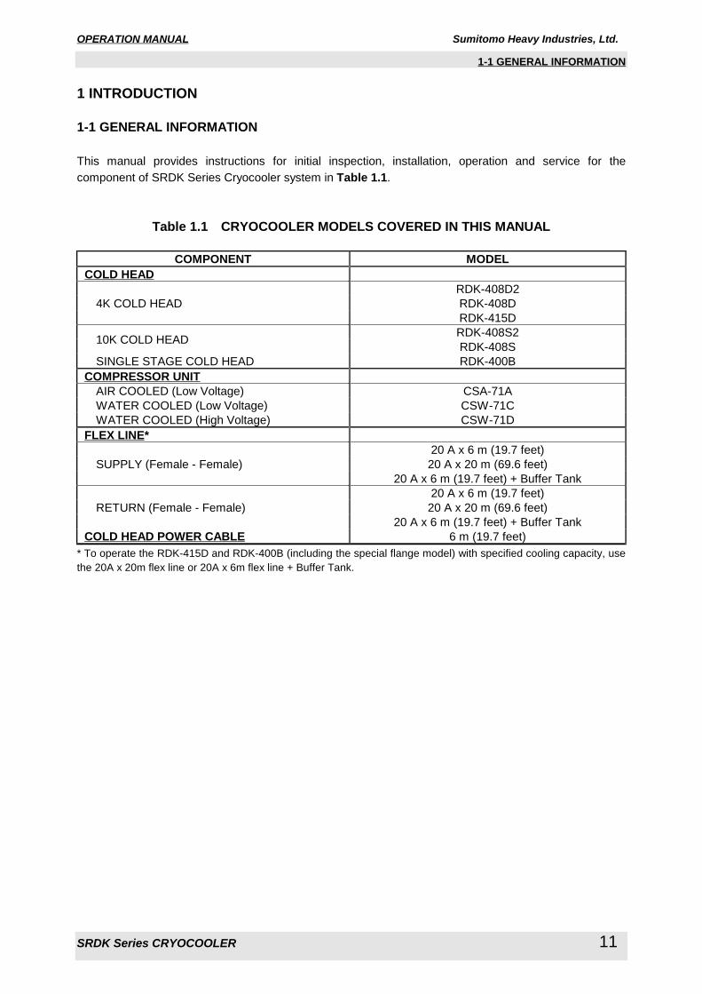
1-1 GENERAL INFORMATION
1 INTRODUCTION
1-1 GENERAL INFORMATION
This manual provides instructions for initial inspection, installation, operation and service for the
component of SRDK Series Cryocooler system in Table 1.1.
Table 1.1 CRYOCOOLER MODELS COVERED IN THIS MANUAL
COMPONENT MODEL COLD HEAD
RDK-408D2
RDK-408D 4K COLD HEAD
RDK-415D
RDK-408S2 10K COLD HEAD
RDK-408S
SINGLE STAGE COLD HEAD RDK-400B
COMPRESSOR UNIT AIR COOLED (Low Voltage) CSA-71A
WATER COOLED (Low Voltage) CSW-71C
WATER COOLED (High Voltage) CSW-71D
FLEX LINE*20 A x 6 m (19.7 feet)
20 A x 20 m (69.6 feet) SUPPLY (Female - Female)
20 A x 6 m (19.7 feet) + Buffer Tank
20 A x 6 m (19.7 feet)
20 A x 20 m (69.6 feet) RETURN (Female - Female)
20 A x 6 m (19.7 feet) + Buffer Tank
COLD HEAD POWER CABLE 6 m (19.7 feet)
* To operate the RDK-415D and RDK-400B (including the special flange model) with specified cooling capacity, use
the 20A x 20m flex line or 20A x 6m flex line + Buffer Tank.

OPERATION MANUAL Sumitomo Heavy Industries, Ltd.
SRDK Series CRYOCOOLER 12
1-2 SRDK SERIES CRYOCOOLER
1-2 SRDK SERIES CRYOCOOLER
The SRDK Series Cryocooler consists of a Cold Head, Compressor Unit, Flex Lines, and Cold Head
Power Cable.
The RDK series Cold Head is a GM cycle cryo-refrigerator. The function of the Cold Head is to produce
continuous closed-cycle refrigeration at temperatures, depending upon the heat load imposed.
The Cold Head has three (3) major components: the drive unit; the cylinder; and the displacer-regenerator
assembly, which is located inside the cylinder.
RDK-408D2 & RDK-408D & RDK-415D 4K Cold Heads are applied rare earth material for the second
stage displacer to produce 4K temperature. The second stage cooling capacity is approximately 1.0W at
4.2K for RDK-408D2 & RDK-408D, and 1.5W at 4.2K for RDK-415D.
RDK-408S2 & RDK-408S 10K Cold Head is the standard type Cold Head which are modified to produce
more cooling capacity for the second stage cold station compared with SHI previous standard type Cold
Head.
The second stage cooling capacity of RDK-408S2 & RDK-408S Cold Head is approximately 5W at 10K.
RDK-400B Single Stage Cold Head has only first stage displacer for cooling the shield.
The cooling capacity of RDK-400B is approximately 54W at 40K.
The Compressor Unit is required to operate the Cold Head. The Compressor Unit will provide the power
and the high-pressure helium gas for the Cold Head, and consisted of a compressor capsule, a cooling
system and lubricating oil mist Adsorber.
Functionally, the high-pressure helium gas from the Compressor Unit will be supplied to the Cold Head
through the helium gas supply connector. The supply gas will be passed into the displacer-regenerator
assembly, come out through the displacer-regenerator assembly to the crankcase through the motor
housing, and finally will be returned to the Compressor Unit through the helium gas return connector. The
helium gas expansion in the displacer-regenerator assembly will provide cooling condition for the first and
second-stage cold stations.
The Cryocooler requires the routine maintenance to keep the performance. The Adsorber replacement of
the Compressor Unit is required every 20,000 operating hours. The acting parts replacement of the Cold
Head is required to maintain every 10,000 operating hours.

OPERATION MANUAL Sumitomo Heavy Industries, Ltd.
SRDK Series CRYOCOOLER 13
1-2 SRDK SERIES CRYOCOOLER
Return Flex Line
(green mark)
Air Cooled
Compressor Unit
Cold Head
Cooling Air
Flow
Supply Flex Line
(yellow mark)
Cold Head
Power Cable
Input Power Cable
Water Cooled
Compressor Unit
Supply Flex Line
(yellow mark)
Return Flex Line
(green mark)
Cold Head
Power Cable
Input Power Cable
Cooling Water
Flow
Cold Head
WATER COOLED SYSTEM
AIR COOLED SYSTEM
Figure 1.1 SRDK SERIES CRYOCOOLER SYSTEM

OPERATION MANUAL Sumitomo Heavy Industries, Ltd.
SRDK Series CRYOCOOLER 14
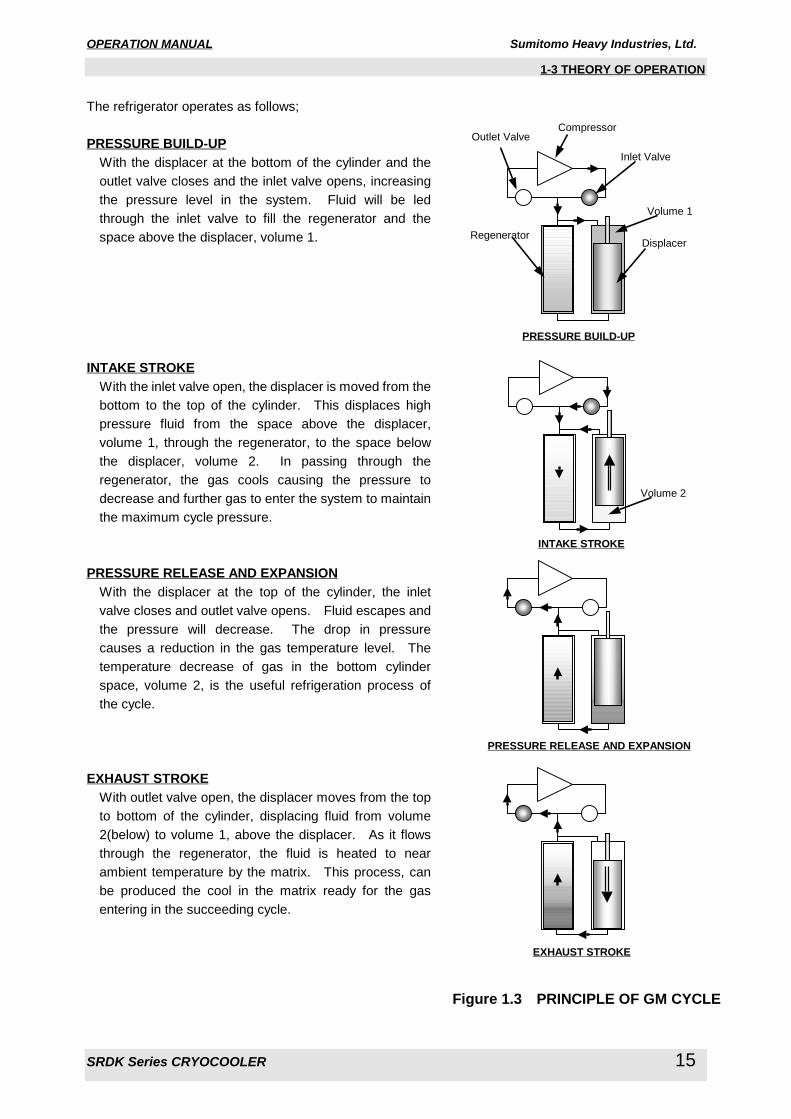
1-3 THEORY OF OPERATION
1-3 THEORY OF OPERATION
The SUMITOMO Helium Refrigerator operates on the GM (Gifford-McMahon) cycle.
The GM cycle is shown schematically in Figure 1.2 and consisted of a cylinder, closed at both ends, and
containing a displacer of a length about three quarters of the cylinder. The displacer is connected to a
drive mechanism so that it can be operated reciprocating action in the cylinder. The two volumes, one for
above and another for below the displacer, can be varied from zero to maximum but the total volume
remains constantly.
Figure 1.2 SCHEMATIC DIAGRAM OF GM CYCLE REFRIGERATOR
The two spaces are connected through a thermal regenerator and to a gas supply. The gas supply
system is consisted of inlet and outlet valves, a helium gas compressor and high and low pressure
reservoirs. The valves are coupled to the rotary drive mechanism and their operation is synchronized with
the position of the displacer. A heat exchanger is included downstream of the helium gas compressor to
cool down the gas to ambient temperature after compression.
The pressure above and below the displacer will be the same level except for small pressure drops across
the regenerator when gas is flowing through it. The basic function for the displacer will be required to
displace a volume in the cylinder so that the gas will be moved up and down in the cylinder without
mechanical work.
Pressure in the system is increased or decreased by operation of the inlet or outlet valves.
The displacer is fit loosely in the cylinder except at the top equipped with a dynamic (sliding) seal to prevent
gas leakage through the space between displacer and cylinder.
The regenerator will be consisted of metallic material divided finely will cool the gas passing downward to
the cold space and heat the gas passing upward from the cold space.
DisplacerRegenerator
Inlet Valve
Outlet Valve
Compressor
OPERATION MANUAL Sumitomo Heavy Industries, Ltd.
SRDK Series CRYOCOOLER 15
1-3 THEORY OF OPERATION
The refrigerator operates as follows;
PRESSURE BUILD-UPWith the displacer at the bottom of the cylinder and the
outlet valve closes and the inlet valve opens, increasing
the pressure level in the system. Fluid will be led
through the inlet valve to fill the regenerator and the
space above the displacer, volume 1.
INTAKE STROKEWith the inlet valve open, the displacer is moved from the
bottom to the top of the cylinder. This displaces high
pressure fluid from the space above the displacer,
volume 1, through the regenerator, to the space below
the displacer, volume 2. In passing through the
regenerator, the gas cools causing the pressure to
decrease and further gas to enter the system to maintain
the maximum cycle pressure.
PRESSURE RELEASE AND EXPANSIONWith the displacer at the top of the cylinder, the inlet
valve closes and outlet valve opens. Fluid escapes and
the pressure will decrease. The drop in pressure
causes a reduction in the gas temperature level. The
temperature decrease of gas in the bottom cylinder
space, volume 2, is the useful refrigeration process of
the cycle.
EXHAUST STROKEWith outlet valve open, the displacer moves from the top
to bottom of the cylinder, displacing fluid from volume
2(below) to volume 1, above the displacer. As it flows
through the regenerator, the fluid is heated to near
ambient temperature by the matrix. This process, can
be produced the cool in the matrix ready for the gas
entering in the succeeding cycle.
DisplacerRegenerator
Inlet Valve
Outlet ValveCompressor
Volume 2
Volume 1
INTAKE STROKE
PRESSURE RELEASE AND EXPANSION
EXHAUST STROKE
PRESSURE BUILD-UP
Figure 1.3 PRINCIPLE OF GM CYCLE

OPERATION MANUAL Sumitomo Heavy Industries, Ltd.
SRDK Series CRYOCOOLER 16
2-1 GENERAL
2 INSTALLATION
<Warning about electric shock>This cryocooler includes a high-voltage section. Touching it may result in electric shock.
Handle it with extreme care.
Make sure no power is applied to the compressor unit before starting the installation. Failing to
observe this precaution may result in electric shock.
2-1 GENERAL
This section describes the installation of the Cold Head and the Compressor Unit, and how to connect the
Flex Lines and electrical cables. Be sure to read this section before installing the cryocooler.
2-2 TOOLS FOR INSTALLATION
The following tools are required for SRDK Series Cryocooler Installation.
Table 2.1 REQUIRED TOOLS FOR INSTALLATION
TOOLS REMARK1 1“ Open-end wrench For Flex Line connection
2 1-1/8“ Open-end wrench For Flex Line connection
3 1-3/16“ Open-end wrench For Flex Line connection
4 Vacuum grease For O-ring of Vacuum Chamber
5 Screwdriver (phillips(+), flathead(-)) For Cold Head Cable and Input Power Cable connection
6 Liquid Leak Detector For leak check
7 Cotton wipers For leak check
8 Bar wrench for M4 For Cold Head Installation to Vacuum Chamber
WARNING
OPERATION MANUAL Sumitomo Heavy Industries, Ltd.
SRDK Series CRYOCOOLER 17
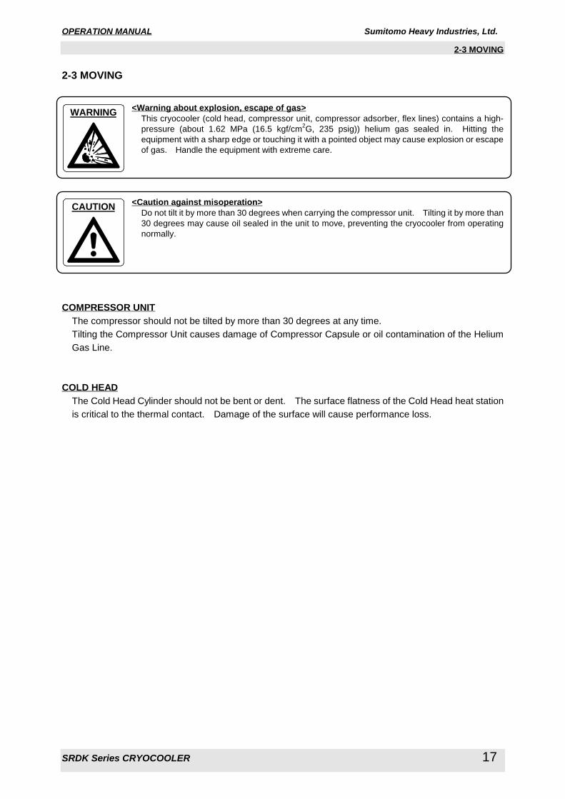
2-3 MOVING
2-3 MOVING
<Warning about explosion, escape of gas>This cryocooler (cold head, compressor unit, compressor adsorber, flex lines) contains a high-
pressure (about 1.62 MPa (16.5 kgf/cm2G, 235 psig)) helium gas sealed in. Hitting the
equipment with a sharp edge or touching it with a pointed object may cause explosion or escape
of gas. Handle the equipment with extreme care.
<Caution against misoperation>Do not tilt it by more than 30 degrees when carrying the compressor unit. Tilting it by more than
30 degrees may cause oil sealed in the unit to move, preventing the cryocooler from operating
normally.
COMPRESSOR UNITThe compressor should not be tilted by more than 30 degrees at any time.
Tilting the Compressor Unit causes damage of Compressor Capsule or oil contamination of the Helium
Gas Line.
COLD HEADThe Cold Head Cylinder should not be bent or dent. The surface flatness of the Cold Head heat station
is critical to the thermal contact. Damage of the surface will cause performance loss.
WARNING
CAUTION

OPERATION MANUAL Sumitomo Heavy Industries, Ltd.
SRDK Series CRYOCOOLER 18
2-4 SITE REQUIREMENT
2-4 SITE REQUIREMENT
<Caution against misoperation>Do not use inverter for the main power source of the compressor unit. Operating with inverter
may result in the damage or malfunction of the compressor electric circuit.
Avoid using the transformer for the main power source of the compressor unit. If the
transformer is installed at the upstream of the unit, lacking phase protection circuit with the
cryocooler occurs in a malfunction. That may result in misoperation or malfunction. When
using the transformer, install the other lacking phase protection device in upstream of the
transformer.
Secure enough space around the compressor unit for heat radiation and maintenance. Failing
to secure enough space may result in misoperation or malfunction. (See the technical
instruction of the compressor unit used, for details.)
If the compressor unit used is the CSA-71A (air cooled, low voltage type), sufficient space is
required for venting. Failing to secure sufficient space may result in misoperation or
malfunction. (See the CSA-71A technical instruction, for details.)
If the compressor unit used is the CSA-71A (air cooled, low voltage type), it should be installed
in a clean environment. Installing it in a dusty environment such as inside a factory will require
frequent cleaning of the cooler fins or may result in misoperation or malfunction.
If the compressor unit used is a water-cooled type (CSW-71C, CSW-71D), use cooling water
with appropriate temperature, flow rate and water quality. Using inappropriate cooling water
may result in misoperation or malfunction. (See the technical instruction of the compressor unit
used, for details.)
If the compressor unit used is a water-cooled type (CSW-71C, CSW-71D), do not use the
demineralized water for cooling water. Using demineralized water for cooling water may result
in water leakage or malfunction.
“IMPORTANT”See “TECHNICAL INSTRUCTION” of Compressor Unit used, for detail of Site Requirement.
The Compressor Unit can be installed at the field as complying with the Site Requirement;
CAUTION
OPERATION MANUAL Sumitomo Heavy Industries, Ltd.
SRDK Series CRYOCOOLER 19
2-4 SITE REQUIREMENT
2-4-1 REQUIRED FOR AIR COOLED COMPRESSOR UNIT
・ An almost level and even area in the field will be selected to install the Compressor Unit.
・ An area to be influenced by splashing water and/or dusts will not be selected to install the Compressor
Unit.
・ A clean environmental condition without dirt and/or free from an exhausted heat will be selected to install
the Compressor Unit in the field.
・ An efficient ventilated area will be required to free from an exhausted heat of the Compressor Unit in the
field.
・ A suitable air conditioning capacity will be secured for an installing area for the Compressor Unit in the
field.
・ Any object and/or obstacle cannot be positioned on a ventilation fan outlet in a top area of the enclosure
and/or on surroundings of the Compressor Cooler.
・ Any heat sensitive object cannot be positioned on surroundings of the Compressor Unit.
AMBIENT TEMPERATURE CONDITIONThe ambient temperature must be between 5 deg.C (41 deg.F) and 28 deg.C (82.4 deg.F) to get the
specified cooling capacity. The system can operate up to 35 deg.C (95 deg.F) with less than 5%
cooling capacity down. The maximum relative air humidity is 85%RH.
HELIUM SUPPLY SYSTEMA helium supply system is necessary if you need to decontaminate the helium gas, or or charge the
helium gas that has leaked out of the system. A helium supply system includes a Grade 5 (99.999%
up pure) helium gas bottle, a regulator, an outlet valve, and a charging hose or equivalent delivery line.
POWER SOURCEEnsure the correct AC power source is available for the Compressor Unit. See “TECHNICAL
INSTRUCTION” of CSA-71A, for AC power source requirement.
SAFETY / SEISMIC REQUIREMENTSecure to lock the locking device of compressor castor.
SERVICE AREAAir-cooled Compressor Unit should have enough space for air-flow as shown in “TECHNICAL
INSTRUCTION” of CSA-71A.

OPERATION MANUAL Sumitomo Heavy Industries, Ltd.
SRDK Series CRYOCOOLER 20
2-4 SITE REQUIREMENT
2-4-2 REQUIRED FOR WATER COOLED COMPRESSOR UNIT
・ An almost level and even area in the field will be selected to install the Compressor Unit.
・ An area to be influenced by splashing water and/or dusts will not be selected to install the Compressor
Unit.
・ A clean environmental condition without dirt and/or free from an exhausted heat will be selected to install
the Compressor Unit in the field.
・ A quality of cooling water will be secured to use for an appropriate cooling of the Compressor Unit.
・ Any heat sensitive object cannot be positioned on surroundings of the Compressor Unit.
AMBIENT TEMPERATURE CONDITIONThe ambient temperature must be between 5 deg.C (41 deg.F) and 28 deg.C (82.4 deg.F) to get the
specified cooling capacity. The system can operate up to 35 deg.C (95 deg.F) with less than 5%
cooling capacity down. The maximum relative air humidity is 85%RH.
HELIUM SUPPLY SYSTEMA helium supply system is necessary if you need to decontaminate the helium gas, or charge the
helium gas that has leaked out of the system. A helium supply system includes a Grade 5 (99.999%
up pure) helium gas bottle, a regulator, an outlet valve, and a charging hose or equivalent delivery line.
POWER SOURCEEnsure the correct AC power source is available for the Compressor Unit. See “TECHNICAL
INSTRUCTION” of Compressor Unit used, for AC power source requirement.
COOLING WATEREnsure the correct cooling water is available for the Compressor Unit. See “TECHNICAL
INSTRUCTION” of Compressor Unit used, for the cooling water requirements.
ANTIFREEZEOperating with Antifreeze (50/50 % mixture of water and ethylene glycol), the flow rate shall be 10%
larger than water flow rate and the pressure drop through the cooling water line will be 40% larger.
The larger circulating pump will be required for the Antifreeze. The admissible capacity range for
circulation pump will be more than 8 liter/min (2.1 gal./min) for flow rate and 0.29 MPa (3 kgf/cm2G, 42
psig) for the pressure drop.
SAFETY / SEISMIC REQUIREMENTSecure to lock the locking device of compressor castor.
SERVICE AREAThe Compressor Unit should have enough space as shown in “TECHNICAL INSTRUCTION” of
Compressor Unit used.
OPERATION MANUAL Sumitomo Heavy Industries, Ltd.
SRDK Series CRYOCOOLER 21
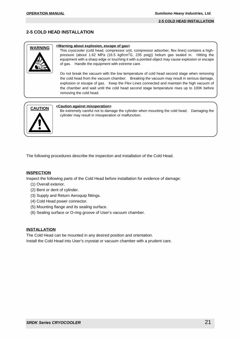
2-5 COLD HEAD INSTALLATION
2-5 COLD HEAD INSTALLATION
<Warning about explosion, escape of gas>This cryocooler (cold head, compressor unit, compressor adsorber, flex lines) contains a high-
pressure (about 1.62 MPa (16.5 kgf/cm2G, 235 psig)) helium gas sealed in. Hitting the
equipment with a sharp edge or touching it with a pointed object may cause explosion or escape
of gas. Handle the equipment with extreme care.
Do not break the vacuum with the low temperature of cold head second stage when removing
the cold head from the vacuum chamber. Breaking the vacuum may result in serious damage,
explosion or escape of gas. Keep the Flex Lines connected and maintain the high vacuum of
the chamber and wait until the cold head second stage temperature rises up to 100K before
removing the cold head.
<Caution against misoperation>Be extremely careful not to damage the cylinder when mounting the cold head. Damaging the
cylinder may result in misoperation or malfunction.
The following procedures describe the inspection and installation of the Cold Head.
INSPECTIONInspect the following parts of the Cold Head before installation for evidence of damage:
(1) Overall exterior.
(2) Bent or dent of cylinder.
(3) Supply and Return Aeroquip fittings.
(4) Cold Head power connector.
(5) Mounting flange and its sealing surface.
(6) Sealing surface or O-ring groove of User’s vacuum chamber.
INSTALLATIONThe Cold Head can be mounted in any desired position and orientation.
Install the Cold Head into User’s cryostat or vacuum chamber with a prudent care.
CAUTION
WARNING

OPERATION MANUAL Sumitomo Heavy Industries, Ltd.
SRDK Series CRYOCOOLER 22
2-6 COMPRESSOR UNIT INSTALLATION
2-6 COMPRESSOR UNIT INSTALLATION
<Warning about electric shock>Do not install the equipment near places subject to condensation such as a watering place.
Failing to observe this precaution may result in electric shock or malfunction.
Do not install the equipment in a dusty environment. Failing to observe this precaution may
result in electric shock or malfunction.
<Warning about explosion, escape of gas>This cryocooler (cold head, compressor unit, compressor adsorber, flex lines) contains a high-
pressure (about 1.62 MPa (16.5 kgf/cm2G, 235 psig)) helium gas sealed in. Hitting the
equipment with a sharp edge or touching it with a pointed object may cause explosion or escape
of gas. Handle the equipment with extreme care.
<Caution against misoperation>This cryocooler is intended for the exclusive use indoors. It cannot be used outdoors. Failing
to observe this precaution may prevent the cryocooler from operating normally.
Do not get onto the compressor unit or put an object on top of it. Failing to observe this
precaution may prevent the cryocooler from operating normally or cause injury.
Secure enough space around the compressor unit for heat radiation and maintenance. Failing
to secure enough space may result in misoperation or malfunction. (See the technical
instruction of the compressor unit used, for details.)
If the compressor unit used is the CSA-71A (air cooled, low voltage type), sufficient space is
required for venting. Failing to secure sufficient space may result in misoperation or
malfunction. (See the CSA-71A technical instruction, for details.)
The procedures including the inspection and installation of the Compressor Unit will be mentioned below.
WARNING
CAUTION
WARNING
OPERATION MANUAL Sumitomo Heavy Industries, Ltd.
SRDK Series CRYOCOOLER 23
2-6 COMPRESSOR UNIT INSTALLATION
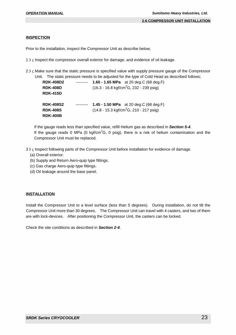
INSPECTION
Prior to the installation, inspect the Compressor Unit as describe below;
1) Inspect the compressor overall exterior for damage, and evidence of oil leakage.
2) Make sure that the static pressure is specified value with supply pressure gauge of the Compressor
Unit. The static pressure needs to be adjusted for the type of Cold Head as described follows;
RDK-408D2 --------- 1.60 - 1.65 MPa at 20 deg.C (68 deg.F)
RDK-408D (16.3 - 16.8 kgf/cm2G, 232 - 239 psig)
RDK-415D
RDK-408S2 --------- 1.45 - 1.50 MPa at 20 deg.C (68 deg.F)
RDK-408S (14.8 - 15.3 kgf/cm2G, 210 - 217 psig)
RDK-400B
If the gauge reads less than specified value, refill Helium gas as described in Section 5-4.
If the gauge reads 0 MPa (0 kgf/cm2G, 0 psig), there is a risk of helium contamination and the
Compressor Unit must be replaced.
3) Inspect following parts of the Compressor Unit before installation for evidence of damage.
(a) Overall exterior.
(b) Supply and Return Aero-quip type fittings.
(c) Gas charge Aero-quip type fittings.
(d) Oil leakage around the base panel.
INSTALLATION
Install the Compressor Unit to a level surface (less than 5 degrees). During installation, do not tilt the
Compressor Unit more than 30 degrees. The Compressor Unit can travel with 4 casters, and two of them
are with lock-devices. After positioning the Compressor Unit, the casters can be locked.
Check the site conditions as described in Section 2-4.
OPERATION MANUAL Sumitomo Heavy Industries, Ltd.
SRDK Series CRYOCOOLER 24
2-7 CONNECTING FLEX LINES
2-7 CONNECTING FLEX LINES
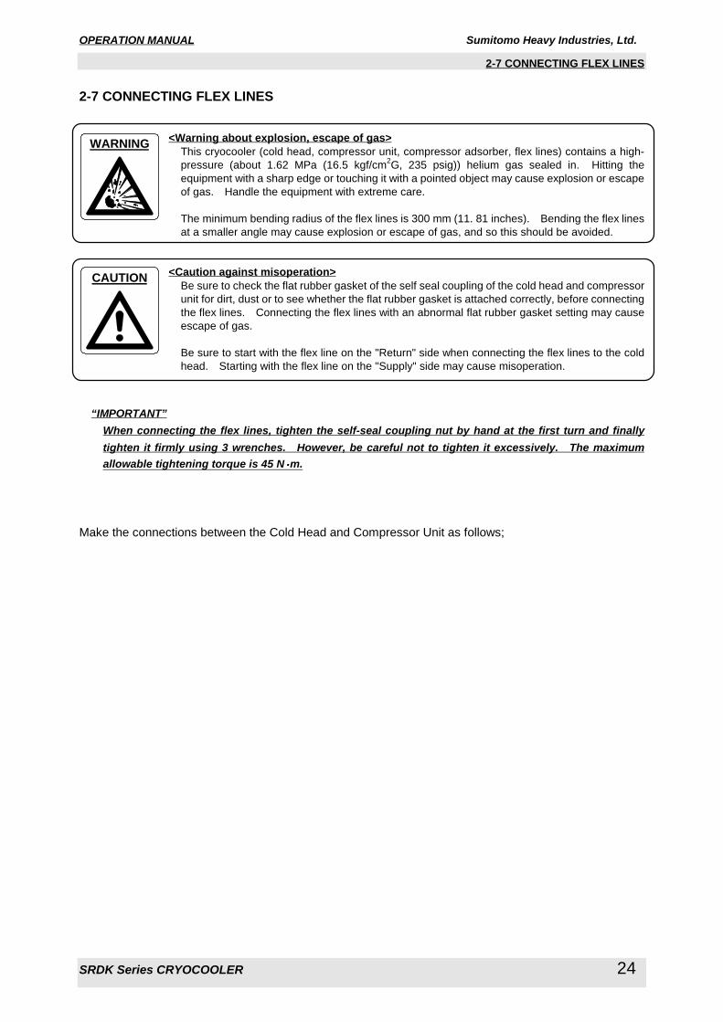
<Warning about explosion, escape of gas>This cryocooler (cold head, compressor unit, compressor adsorber, flex lines) contains a high-
pressure (about 1.62 MPa (16.5 kgf/cm2G, 235 psig)) helium gas sealed in. Hitting the
equipment with a sharp edge or touching it with a pointed object may cause explosion or escape
of gas. Handle the equipment with extreme care.
The minimum bending radius of the flex lines is 300 mm (11. 81 inches). Bending the flex lines
at a smaller angle may cause explosion or escape of gas, and so this should be avoided.
<Caution against misoperation>Be sure to check the flat rubber gasket of the self seal coupling of the cold head and compressor
unit for dirt, dust or to see whether the flat rubber gasket is attached correctly, before connecting
the flex lines. Connecting the flex lines with an abnormal flat rubber gasket setting may cause
escape of gas.
Be sure to start with the flex line on the "Return" side when connecting the flex lines to the cold
head. Starting with the flex line on the "Supply" side may cause misoperation.
“IMPORTANT”When connecting the flex lines, tighten the self-seal coupling nut by hand at the first turn and finallytighten it firmly using 3 wrenches. However, be careful not to tighten it excessively. The maximumallowable tightening torque is 45 N・・・・m.
Make the connections between the Cold Head and Compressor Unit as follows;
WARNING
CAUTION
OPERATION MANUAL Sumitomo Heavy Industries, Ltd.
SRDK Series CRYOCOOLER 25
2-7 CONNECTING FLEX LINES
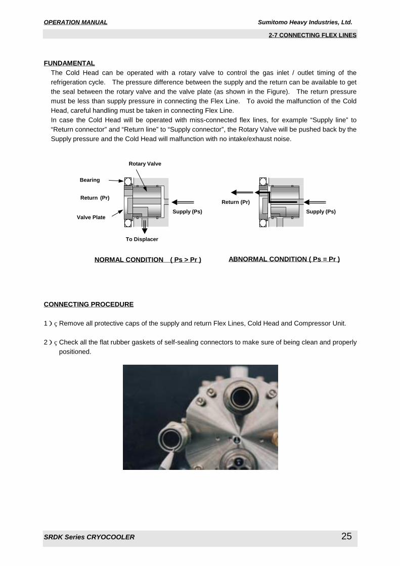
FUNDAMENTALThe Cold Head can be operated with a rotary valve to control the gas inlet / outlet timing of the
refrigeration cycle. The pressure difference between the supply and the return can be available to get
the seal between the rotary valve and the valve plate (as shown in the Figure). The return pressure
must be less than supply pressure in connecting the Flex Line. To avoid the malfunction of the Cold
Head, careful handling must be taken in connecting Flex Line.
In case the Cold Head will be operated with miss-connected flex lines, for example “Supply line” to
“Return connector” and “Return line” to “Supply connector”, the Rotary Valve will be pushed back by the
Supply pressure and the Cold Head will malfunction with no intake/exhaust noise.
CONNECTING PROCEDURE
1) Remove all protective caps of the supply and return Flex Lines, Cold Head and Compressor Unit.
2) Check all the flat rubber gaskets of self-sealing connectors to make sure of being clean and properly
positioned.
Valve Plate
Bearing
Rotary Valve
Supply (Ps)
Return (Pr)
Supply (Ps)Return (Pr)
To Displacer
NORMAL CONDITION ( Ps > Pr ) ABNORMAL CONDITION ( Ps = Pr )
OPERATION MANUAL Sumitomo Heavy Industries, Ltd.
SRDK Series CRYOCOOLER 26
2-7 CONNECTING FLEX LINES
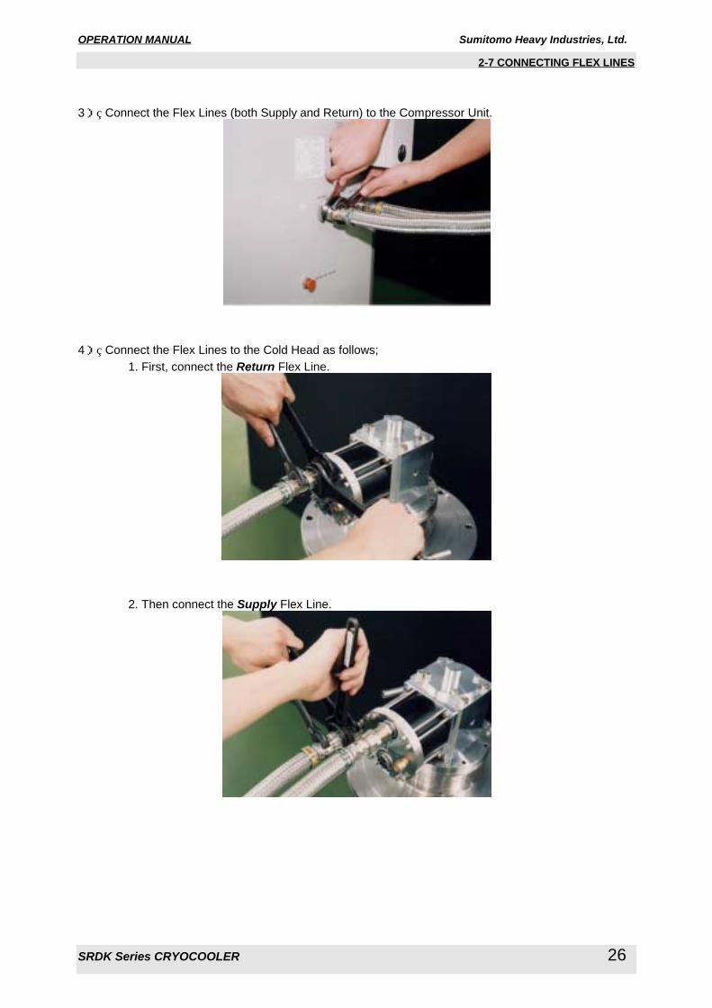
3) Connect the Flex Lines (both Supply and Return) to the Compressor Unit.
4) Connect the Flex Lines to the Cold Head as follows;
1. First, connect the Return Flex Line.
2. Then connect the Supply Flex Line.

OPERATION MANUAL Sumitomo Heavy Industries, Ltd.
SRDK Series CRYOCOOLER 27
2-7 CONNECTING FLEX LINES
CONNECTING PROCEDURE (in case of using the “Buffer Tank”)
In case of using the “Buffer Tank”, insert the “Buffer Tank” between the Compressor Unit and Flex Lines.
Refer to the Figure 2.1, outline view of the “Buffer Tank”, and the Figure 2.2, “Buffer Tank”
interconnecting diagram.
Connect the “Buffer Tank” with following procedure.
1) Connect the female coupling of “Tee-Adapter” to the male connector of the Compressor Unit for both
“Supply” and “Return”.
2) Place the “Buffer Tank” at the right side of the Compressor Unit.
3) Connect the “Tee-Adapter” and “Buffer Tank” by two “8A x 1m Flex Line”.
4) Connect the Flex Lines to the Tee-Adapters. Do not miss-match the “Supply” and “Return” marking
for both Flex Lines and Compressor Unit

OPERATION MANUAL Sumitomo Heavy Industries, Ltd.
SRDK Series CRYOCOOLER 28
2-7 CONNECTING FLEX LINES
Figure 2.1 OUTLINE VIEW OF THE “BUFFER TANK”

OPERATION MANUAL Sumitomo Heavy Industries, Ltd.
SRDK Series CRYOCOOLER 29
2-7 CONNECTING FLEX LINES
Figure 2.2 “BUFFER TANK” INTERCONNECTING DIAGRAM
OPERATION MANUAL Sumitomo Heavy Industries, Ltd.
SRDK Series CRYOCOOLER 30
2-7 CONNECTING FLEX LINES
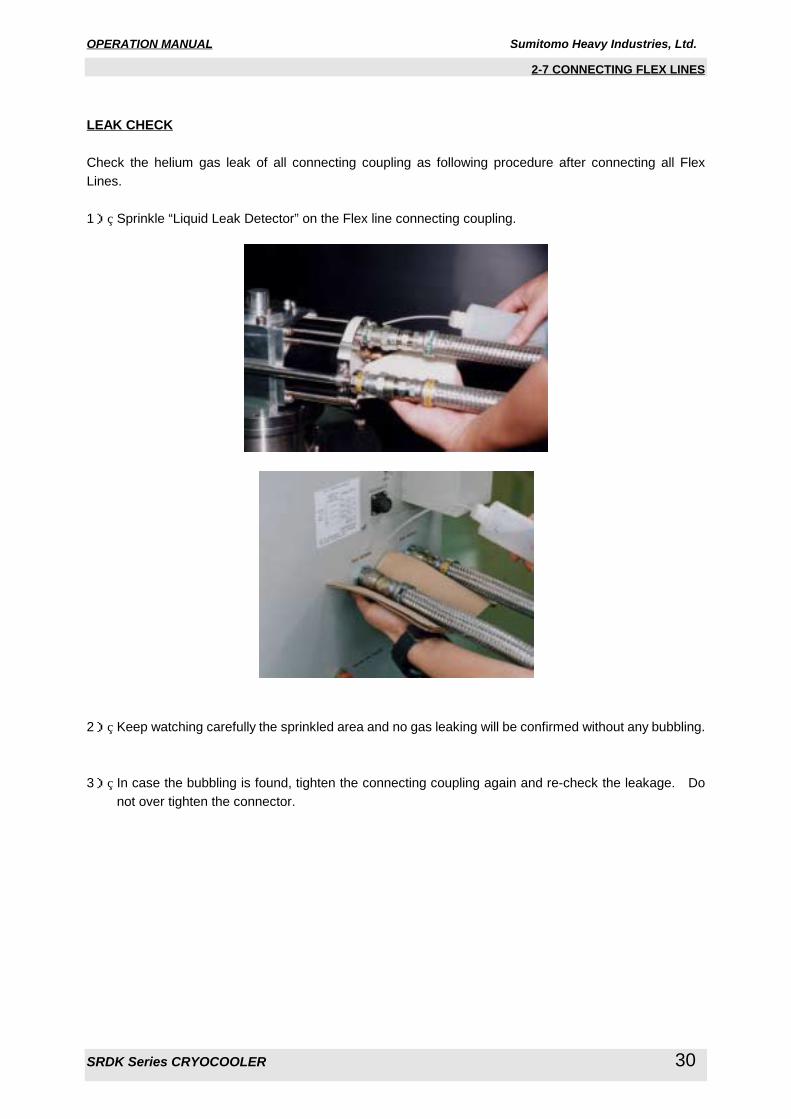
LEAK CHECK
Check the helium gas leak of all connecting coupling as following procedure after connecting all Flex
Lines.
1) Sprinkle “Liquid Leak Detector” on the Flex line connecting coupling.
2) Keep watching carefully the sprinkled area and no gas leaking will be confirmed without any bubbling.
3) In case the bubbling is found, tighten the connecting coupling again and re-check the leakage. Do
not over tighten the connector.

OPERATION MANUAL Sumitomo Heavy Industries, Ltd.
SRDK Series CRYOCOOLER 31
2-8 COLD HEAD POWER CABLE CONNECTION
2-8 COLD HEAD POWER CABLE CONNECTION
<Warning about electric shock>Make sure no power is applied to the compressor unit before starting operation when connecting
or disconnecting the cold head power cable. Failing to observe this precaution may result in
electric shock.
Make the Cold Head Power Cable connection as follows;
Phillips Screwdriver(+) is required to connect the Cold Head Power Cable.
CONNECTION TO THE COLD HEAD
1. FOR CONVERSION CONNECTOR TYPEConnect the Cold head Cable to the Conversion Connector directly.
2. FOR LIQUID TIGHT CONNECTOR TYPE1) Set the connector of the Cold Head Cable to the terminal pins on the Cold Head Drive Motor.
WARNING

OPERATION MANUAL Sumitomo Heavy Industries, Ltd.
SRDK Series CRYOCOOLER 32
2-8 COLD HEAD POWER CABLE CONNECTION
2) Connect the ground terminal of the Cold Head Cable (green color wire with ring terminal) to rear
cover of Cold Head Drive Motor.
3) Mount the Terminal Cover on the Cold Head Motor with securing four(4) screws.
4) Tighten the Cable Clamp of the Terminal Cover.
OPERATION MANUAL Sumitomo Heavy Industries, Ltd.
SRDK Series CRYOCOOLER 33
2-8 COLD HEAD POWER CABLE CONNECTION
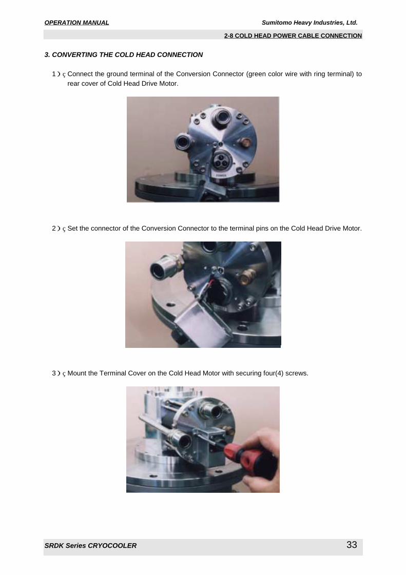
3. CONVERTING THE COLD HEAD CONNECTION
1) Connect the ground terminal of the Conversion Connector (green color wire with ring terminal) to
rear cover of Cold Head Drive Motor.
2) Set the connector of the Conversion Connector to the terminal pins on the Cold Head Drive Motor.
3) Mount the Terminal Cover on the Cold Head Motor with securing four(4) screws.
OPERATION MANUAL Sumitomo Heavy Industries, Ltd.
SRDK Series CRYOCOOLER 34
2-8 COLD HEAD POWER CABLE CONNECTION
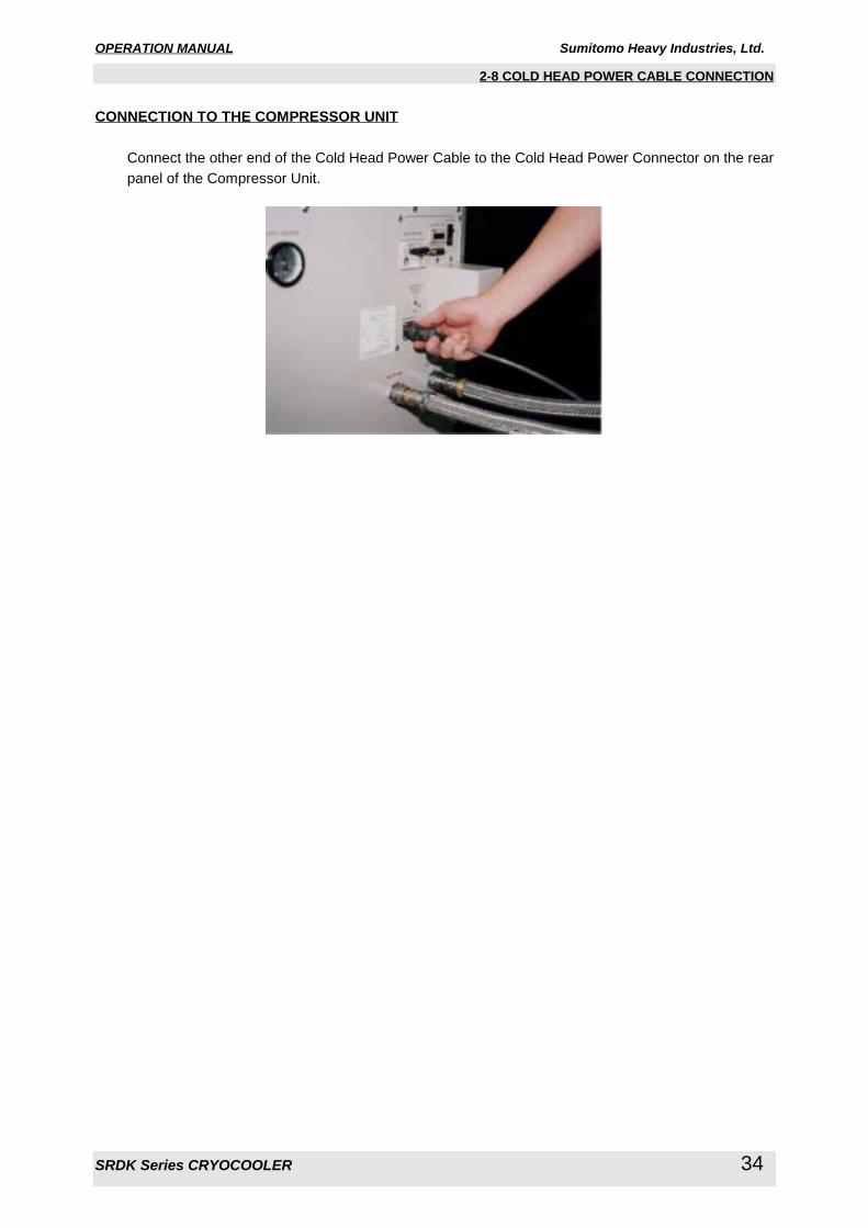
CONNECTION TO THE COMPRESSOR UNIT
Connect the other end of the Cold Head Power Cable to the Cold Head Power Connector on the rear
panel of the Compressor Unit.
OPERATION MANUAL Sumitomo Heavy Industries, Ltd.
SRDK Series CRYOCOOLER 35
2-9 INPUT POWER CABLE CONNECTION
2-9 INPUT POWER CABLE CONNECTION
<Warning about electric shock>Make sure the power specification of the cryocooler used conforms to the customer's power
supply before using the equipment. Using the cryocooler with a non-conforming power supply
may result in electric shock or malfunction.
If the compressor unit used is the CSW-71D (water cooled, high voltage type), pay attention to
the setting of the applicable input supply voltage. The product is shipped with the input supply
voltage set to 480V. Before installing the equipment, be sure to check your supply voltage and
change it to the appropriate setting if necessary. Operating the equipment with your supply
voltage different from the setting of the compressor unit may result in electric shock or
malfunction.
Be sure to turn off and Lock Out with OFF position the main power of the customer's power
source before connecting or disconnecting the input power cable to the Compressor Unit, and
then remove the input power cable from the main power. Failing to observe this precaution
may result in electric shock.
Do not change the setting of the dial above the main power switch of the compressor unit under
any circumstances. Failing to observe this precaution may result in electric shock.
<Caution against misoperation>Do not use inverter for the main power source of the compressor unit. Operating with inverter
may result in the damage or malfunction of the compressor electric circuit.
Avoid using the transformer for the main power source of the compressor unit. If the
transformer is installed at the upstream of the unit, lacking phase protection circuit with the
cryocooler occurs in a malfunction. That may result in misoperation or malfunction.
When using the transformer, install the other lacking phase protection device in upstream of the
transformer.
“IMPORTANT”This cryocooler is provided with a phase reverse protection circuit for the input power. If the inputpower is connected with reverse phase, the cryocooler does not start.
“IMPORTANT”See “TECHNICAL INSTRUCTION” of Compressor Unit used, for detail of Input Power Connection.
WARNING
CAUTION

OPERATION MANUAL Sumitomo Heavy Industries, Ltd.
SRDK Series CRYOCOOLER 36
3-1 PRELIMINARY CHECKS
3 OPERATION
<Warning about electric shock>This cryocooler includes a high-voltage section. Touching it may result in electric shock.
Handle it with extreme care.
Make sure the power specification of the cryocooler used conforms to the customer's power
supply before using the equipment. Using the cryocooler with a non-conforming power supply
may result in electric shock or malfunction.
If the compressor unit used is the CSW-71D (water cooled, high voltage type), pay attention to
the setting of the applicable input supply voltage. The product is shipped with the input supply
voltage set to 480V. Before installing the equipment, be sure to check your supply voltage and
change it to the appropriate setting if necessary. Operating the equipment with your supply
voltage different from the setting of the compressor unit may result in electric shock or
malfunction.
Do not change the setting of the dial above the main power switch of the compressor unit under
any circumstances. Failing to observe this precaution may result in electric shock.
<Warning about explosion, escape of gas>This cryocooler (cold head, compressor unit, compressor adsorber, flex lines) contains a high-
pressure (about 1.62 MPa (16.5 kgf/cm2G, 235 psig)) helium gas sealed in. Hitting the
equipment with a sharp edge or touching it with a pointed object may cause explosion or escape
of gas. Handle the equipment with extreme care.
WARNING
WARNING
OPERATION MANUAL Sumitomo Heavy Industries, Ltd.
SRDK Series CRYOCOOLER 37
3-1 PRELIMINARY CHECKS
3-1 PRELIMINARY CHECKS
<Caution against misoperation>This cryocooler (cold head, compressor unit, compressor adsorber, flex lines) is shipped with a
helium gas at about 1.62 MPa (16.5 kgf/cm2G, 235 psig) sealed in. Be sure to adjust the
pressure to an appropriate value according to the cold head used before operating the
equipment. Using the cryocooler at an improper pressure may cause misoperation.
The coldhead employs the special seal to the 2nd stage. The 2nd stage displacer is fit tightly in
the cylinder. Make sure the 2nd stage temperature is less than 28 deg.C before starting up the
cryocooler, or the coldhead may make grinding noise.
“IMPORTANT”This cryocooler is provided with a phase reverse protection circuit for the input power. If the inputpower is connected with reverse phase, the cryocooler does not start.
Prior to starting Cryocooler, confirm that the Compressor Unit and the Cold Head are installed correctly as
described in Section 2.
CHECKING HELIUM GAS PRESSUREMake sure that the static pressure is specified value with supply pressure gauge of the Compressor
Unit.
The static pressure needs to be adjusted for Cold Head as described follows;
COLD HEAD MODEL STATIC PRESSURERDK-408D2 4K Cold Head
RDK-408D 4K Cold Head
RDK-415D 4K Cold Head
1.60 - 1.70 MPa at 20 deg.C (68 deg.F)
(16.3 - 17.3 kgf/cm2G, 232 - 246 psig)
RDK-408S2 10K Cold Head
RDK-408S 10K Cold Head
RDK-400B Single Stage Cold Head
1.45 - 1.55 MPa at 20 deg.C (68 deg.F)
(14.8 - 15.8 kgf/cm2G, 210 - 225 psig)
For RDK-408D2 & 408D & 415D For RDK-408S2 & 408S & 400B
CHECKING ELECTRIC POWER, VOLTAGE AND PHASECheck the line to line voltage and confirm it is ±10% of the specified value to meet the specification
described in each “TECHNICAL INSTRUCTION” for Compressor Unit used.
Confirm the phase of Input power and cable with correctly wired.
CAUTION
OPERATION MANUAL Sumitomo Heavy Industries, Ltd.
SRDK Series CRYOCOOLER 38
3-2 START UP
3-2 START-UP OPERATION
<Caution against misoperation>The cryocooler ON/OFF frequency must be less than 6 times per hour, and the ON/OFF interval
must be more than 3 minutes. The frequent ON/OFF operation may result in damage of
compressor capsule or malfunction.
The cold head drive switch provided with the compressor unit is only used for maintenance. Be
sure to turn it OFF in normal operation. Using the compressor unit with the cold head drive
switch turned ON may result in misoperation or malfunction.
The coldhead employs the special seal to the 2nd stage. The 2nd stage displacer is fit tightly in
the cylinder. Make sure the 2nd stage temperature is less than 28 deg.C before starting up the
cryocooler, or the coldhead may make grinding noise.
“IMPORTANT”This cryocooler is provided with a phase reverse protection circuit for the input power. If the inputpower is connected with reverse phase, the cryocooler does not start.
Start up the Cryocooler as mentioned below;
1) Make sure that the pressure gauge of the Compressor Unit is indicating correct static pressure of
your system with supply pressure gauge.
2) Check the setting of “Drive Switch”, “Cold Head Drive Switch” and “Remote Drive Switch”.
“Drive Switch” --- OFF Position“Cold Head Drive Switch” --- OFF Position“Remote Drive Switch” --- INT Position (for Water Cooled Compressor Unit only)
3) Turn on the "Main Power Switch".
For Air Cooled Compressor Unit For Water Cooled Compressor Unit
4) Turn on the “Drive Switch”.
For Air Cooled Compressor Unit For Water Cooled Compressor Unit
CAUTION
OPERATION MANUAL Sumitomo Heavy Industries, Ltd.
SRDK Series CRYOCOOLER 39
3-3 SHUT DOWN
3-3 SHUT-DOWN OPERATION
<Warning about explosion, escape of gas>Do not break the vacuum with the low temperature of cold head second stage when removing
the cold head from the vacuum chamber. Breaking the vacuum may result in serious damage,
explosion or escape of gas. Keep the Flex Lines connected and maintain the high vacuum of
the chamber and wait until the cold head second stage temperature rises up to 100K before
removing the cold head.
<Caution against misoperation>The cryocooler ON/OFF frequency must be less than 6 times per hour, and the ON/OFF interval
must be more than 3 minutes. The frequent ON/OFF operation may result in damage of
compressor capsule or malfunction.
The cold head drive switch provided with the compressor unit is only used for maintenance. Be
sure to turn it OFF in normal operation. Using the compressor unit with the cold head drive
switch turned ON may result in misoperation or malfunction.
The coldhead employs the special seal to the 2nd stage. The 2nd stage displacer is fit tightly in
the cylinder. Make sure the 2nd stage temperature is less than 28 deg.C before starting up the
cryocooler, or the coldhead may make grinding noise.
Shut down operation for the Cryocooler as mentioned below;
1) Turn off the “Drive Switch”.
For Air Cooled Compressor Unit For Water Cooled Compressor Unit
2) Turn off the “Main Power Switch”.
For Air Cooled Compressor Unit For Water Cooled Compressor Unit
WARNING
CAUTION

OPERATION MANUAL Sumitomo Heavy Industries, Ltd.
SRDK Series CRYOCOOLER 40
3-4 NORMAL OPERATION
3-4 NORMAL OPERATION
<Warning about rotating part>If the compressor unit used is the CSA-71A (air cooled, low voltage type), a venting fanis provided in the exhaust section at the top of the compressor unit. Do not insertforeign substances from the exhaust port under any circumstances. Failing toobserve this precaution may result in injury or malfunction.
“IMPOTANT”If the compressor unit used is the CSA-71A (air cooled, low voltage type), note that the noise level of thewhole equipment may exceed 70 dBA depending on the environment it is used in.
EXHAUST SOUNDStarting Cryocooler, you can hear the gas inlet/outlet sound from the Cold Head. The sound of the
Cold Head is 60 rpm at 50 Hz and 72 rpm at 60 Hz respectively. During this checking, the Compressor
operating pressure will be around 2.5 MPa (25.5 kgf/cm2G, 362 psig).
SUPPLY PRESSURE INDICATIONMonitor the compressor's supply He gas pressure. In the normal operation with adequate heat loads,
the supply helium gas pressure indicates between 2.1 and 2.3 MPa (21.4 and 23.5 kgf/cm2G, 304 and
333 psig). The operating pressure varies according to the heat load of cold head and temperature
around the equipment.
COLD STAGE TEMPERATUREMonitor the Cold Head 1st and 2nd stage temperature. The final temperature of the Cold Head
depends on the heat load such as radiation heat, applied heat load and convection caused by bad
vacuum of the chamber. If the temperature becomes steady state but high, the total heat loads to the
Cold Head is too much. Check the heat loads.
FLEX LINES TEMPERATUREMake sure that the temperature of the supply Flex Line from the Compressor to the Cold Head does not
exceed 40 deg.C (104 deg.F). If the Flex Line temperature is higher, check the conditions of air flow
and cooler fins for Air Cooled Compressor Unit, and water flow for Water Cooled Compressor Unit.
COOLING AIR FLOW (for Air Cooled Compressor Unit)If the system is with Air-Cooled Compressor Unit, identify that the forced draught Fan located at the top
of the Compressor Unit is continuously operating and that cooling air is drawn in through the heat
exchanger and flows out from the top cover of the Compressor Unit. It is required to keep the enough
space around the compressor and the room temperature should be less than 28 deg.C (82.4 deg.F)to
get the refrigeration capacity. The maximum heat output from Compressor is 8.3 kW or 28,320 BTU/h,
therefore, a suitable air-conditioning should be prepared.
COOLING WATER FLOW (for Water Cooled Compressor Unit)If the system is with Water-Cooled Compressor Unit, make sure that the sufficient cooling water is
flowing as shown in the specification described in “TECHNICAL INSTRUCTION” of Compressor Unit
used. The quality of the water should meet the specification (The specification is also described in
“TECHNICAL INSTRUCTION” of Compressor Unit used.) to prevent plugging or calcification.
WARNING
OPERATION MANUAL Sumitomo Heavy Industries, Ltd.
SRDK Series CRYOCOOLER 41
4-1 SIMPLE PROBLEM
4 FUNCTIONAL CHECK
4-1 SIMPLE PROBLEM
This section describes several simple problems that usually occurred. If you have trouble that you cannot
fix according to the following procedure, proceed to “TROUBLE SHOOTING FLOW CHART” described in
Section 6.
4-1-1 PRESSURE
Cryocooler is designed and manufactured to get cooling capacity with specified Helium Gas Pressure. It is
highly recommended to check the pressure. If the indicated pressure is higher than specified value,
reduce the pressure. If it is lower, charge the helium gas. See “TECHNICAL INSTRUCTION” of Cold
Head used, to see the specified pressure of your system.
COLD HEAD MODEL STATIC PRESSURERDK-408D2 4K Cold Head
RDK-408D 4K Cold Head
RDK-415D 4K Cold Head
1.60 - 1.70 MPa at 20 deg.C (68 deg.F)
(16.3 - 17.3 kgf/cm2G, 232 - 246 psig)
RDK-408S2 10K Cold Head
RDK-408S 10K Cold Head
RDK-400B Single Stage Cold Head
1.45 - 1.55 MPa at 20 deg.C (68 deg.F)
(14.8 - 15.8 kgf/cm2G, 210 - 225 psig)
After replacing Cold Head, it will be necessary to charge the Helium Gas because the temperature of the
Cold Head is usually lower than room temperature, therefore the system always lose helium gas.
4-1-2 ROOM TEMPERATURE
Room temperature affects the Cryocooler performance. It is highly recommended to keep the room
temperature in the specified range. See “TECHNICAL INSTRUCTION” of Compressor Unit used, for
details.
COMPRESSOR UNIT MODEL ROOM TEMPERATURE RANGE
CSA-71A, CSW-71C, CSW-71D5 to 28 deg.C (41 to 82.4 deg.F)
28 to 35 deg.C (82.4 to 95 deg.F) with 5% Capacity Loss
4-1-3 MAIN POWER PHASE
The Cryocooler operates with 3 phase mains frequency. The Compressor Units are equipped with phase
reverse protection circuit to protect the Compressor Unit from reverse revolution. The Compressor Unit
will not start, in case the main power is reverse phase. A procedure for the diagnosis of phase failure for
input power caused by miss-wiring will be performed, if the Compressor Unit cannot be operated as normal
in a condition of the “Drive Switch - ON” under the “Main Power Switch - ON”.
OPERATION MANUAL Sumitomo Heavy Industries, Ltd.
SRDK Series CRYOCOOLER 42
4-2 HELIUM LEAK
4-2 HELIUM LEAK
<Warning about explosion, escape of gas>This cryocooler (cold head, compressor unit, compressor adsorber, flex lines) contains a high-
pressure (about 1.62 MPa (16.5 kgf/cm2G, 235 psig)) helium gas sealed in. Hitting the
equipment with a sharp edge or touching it with a pointed object may cause explosion or escape
of gas. Handle the equipment with extreme care.
The Cold Head cannot be performed a required cooling power in normal operations, as the result of the
He-gas pressure reducing gradually in the Cold Head in condition of occurring a He-gas Leak in the
Cryocooler. The Compressor unit will be shut down as the function of the Low Pressure Switch to be
sensed and excessive lower He-gas pressure, and verify the charged He-gas pressure in the Compressor
Unit as specified pressure. The charged He-gas pressure will be indicated individually for each
application, and see “TECHNICAL INSTRUCTION” of the Cold Head used.
COLD HEAD MODEL STATIC PRESSURERDK-408D2 4K Cold Head
RDK-408D 4K Cold Head
RDK-415D 4K Cold Head
1.60 - 1.70 MPa at 20 deg.C (68 deg.F)
(16.3 - 17.3 kgf/cm2G, 232 - 246 psig)
RDK-408S2 10K Cold Head
RDK-408S 10K Cold Head
RDK-400B Single Stage Cold Head
1.45 - 1.55 MPa at 20 deg.C (68 deg.F)
(14.8 - 15.8 kgf/cm2G, 210 - 225 psig)
A Leak detector will be applied to leak area hunting for convenience, and “Liquid Leak Detector” also will
be useful to check the He-gas leaking of couplings for the Flex Line by watching any bubbling carefully, if
the Leak Detector not in use at the field.
WARNING
OPERATION MANUAL Sumitomo Heavy Industries, Ltd.
SRDK Series CRYOCOOLER 43
5-1 GENERAL INFORMATION FOR THE MAINTENANCE
5 MAINTENANCE
<Warning about electric shock>This cryocooler includes a high-voltage section. Touching it may result in electric shock.
Handle it with extreme care.
Make sure no power is applied to the compressor unit before connecting or disconnecting the
cold head power cable. Failing to observe this precaution may result in electric shock.
Be sure to turn off and Lock Out with OFF position the main power of the customer's power
source before connecting or disconnecting the input power cable to the Compressor Unit, and
then remove the input power cable from the main power. Failing to observe this precaution
may result in electric shock.
Do not change the setting of the dial above the main power switch of the compressor unit under
any circumstances. Failing to observe this precaution may result in electric shock.
Be sure to turn off and Lock Out with OFF position the customer's main power before performing
maintenance work such as replacement of fuses. Failing to observe this precaution may result
in electric shock.
<Warning about explosion, escape of gas>This cryocooler (cold head, compressor unit, compressor adsorber, flex lines) contains a high-
pressure (about 1.62 MPa (16.5 kgf/cm2G, 235 psig)) helium gas sealed in. Hitting the
equipment with a sharp edge or touching it with a pointed object may cause explosion or escape
of gas. Handle the equipment with extreme care.
Do not disassemble the equipment for purposes other than maintenance specified in this
service manual under any circumstances. Disassembling the equipment may result in electric
shock, explosion or escape of gas.
The cold head, compressor unit, compressor adsorber and flex lines are pressurized with helium
gas. Purge the helium gas from all pressurized components before disposing. Open the
purging valve gradually or it may result in serious injury.
Do not break the vacuum with the low temperature of cold head second stage when removing
the cold head from the vacuum chamber. Breaking the vacuum may result in serious damage,
explosion or escape of gas. Keep the Flex Lines connected and maintain the high vacuum of
the chamber and wait until the cold head second stage temperature rises up to 100K before
removing the cold head.
<Warning about rotating part>If the compressor unit used is the CSA-71A (air cooled, low voltage type), a venting fan is
provided in the exhaust section at the top of the compressor unit. Do not insert foreign
substances from the exhaust port under any circumstances. Failing to observe this precaution
may result in injury or malfunction.
The Adsorber weight is about 11.0kg. When replace the adsorber, be careful of handling so that
it may not get hurt.
WARNING
WARNING
WARNING
WARNING
OPERATION MANUAL Sumitomo Heavy Industries, Ltd.
SRDK Series CRYOCOOLER 44
5-1 GENERAL INFORMATION FOR THE MAINTENANCE
<Caution against misoperation>Do not get on the compressor unit or put an object on top of it. Failing to observe this
precaution may prevent the cryocooler from operating normally or cause injury.
Secure enough space around the compressor unit for heat radiation and maintenance. Failing
to secure enough space may result in misoperation or malfunction. (See the technical
instruction of the compressor unit used, for details.)
If the compressor unit used is the CSA-71A (air cooled, low voltage type), sufficient space is
required for venting. Failing to secure sufficient space may result in misoperation or
malfunction. (See the CSA-71A technical instruction, for details.)
If the compressor unit used is the CSA-71A (air cooled, low voltage type), it should be installed
in a clean environment. Installing it in a dusty environment such as inside a factory will require
frequent cleaning of the cooler fins or may result in misoperation or malfunction.
If the compressor unit used is a water-cooled type (CSW-71C, CSW-71D), use cooling water
with appropriate temperature, flow rate and water quality. Using inappropriate cooling water
may result in misoperation or malfunction. (See the technical instruction of the compressor unit
used, for details.)
The cold head drive switch provided with the compressor unit is only used for maintenance. Be
sure to turn it OFF in normal operation. Using the compressor unit with the cold head drive
switch turned ON may result in misoperation or malfunction.
5-1 GENERAL INFORMATION FOR THE MAINTENANCE
The SRDK CRYOCOOLER system is to be required the routine maintenance for long term and continuous
as every 10,000 Hrs on an actual installation.
The basic maintenance work is to replace the existing Cold Head composed of acting parts for every
10,000 Hrs operation and additional replacement of oil mist Adsorber of the Compressor Unit for every
20,000 Hrs operation as mentioned in Table 5.1.
Table 5.1 MAINTENANCE SCHEDULE
MAINTENANCE FREQUENCY REMARKSReplace Cold Head’s parts
(Parts inside Cold Head)Every 10,000 Hrs.
Not a User’s Maintenance
Return the Cold Head to SHI.
Replace Compressor Adsorber Every 20,000 Hrs.
Charge Helium Gas to Compressor As required
Compressor Fuse Replacement As required
Cleaning Air Cooler
(Air-Cooled Compressor)At least one time per year
Depending on the Compressor
site conditions.
Cleaning Water Line
(Water-Cooled Compressor)As required Depending on the Water Quality
CAUTION
OPERATION MANUAL Sumitomo Heavy Industries, Ltd.
SRDK Series CRYOCOOLER 45
5-2 COLD HEAD MAINTENANCE
5-2 COLD HEAD MAINTENANCE
The Cold Head is required to replace the sliding parts inside every 10,000 Hrs. This is not a user’s
Maintenance. Replace the Cold Head completely at site and return it to Sumitomo Heavy Industries, Ltd.
for refurbishment.
5-3 COMPRESSOR UNIT MAINTENANCE
“IMPORTANT”See “TECHNICAL INSTRUCTION” of Compressor Unit used, for detail of the Compressor Unitmaintenance.
The Compressor Units are required to replace Adsorber every 20,000 Hrs. The Adsorber is compatible
for both air-cooled and water-cooled Compressor.
FOR “AIR COOLED” COMPRESSORIt is important to keep the heat exchanger clean. It is required to clean the heat exchanger once a year.
However, if the room is dirty and/or dusty, it will be required to clean the heat exchanger more than once
a year.
FOR “WATER COOLED” COMPRESSORThe Compressor requires cooling water. The quality of the cooling water should meet the specification
described “TECHNICAL INSTRUCTION” of Compressor Unit used. It can be required to clean the
cooling water line inside/outside the Compressor, if the cooling water is insufficient.
OPERATION MANUAL Sumitomo Heavy Industries, Ltd.
SRDK Series CRYOCOOLER 46
5-4 HELIUM GAS CHARGING
5-4 HELIUM GAS CHARGING
<Warning about explosion, escape of gas>This cryocooler (cold head, compressor unit, compressor adsorber, flex lines) contains a high-
pressure (about 1.62 MPa (16.5 kgf/cm2G, 235 psig)) helium gas sealed in. Hitting the
equipment with a sharp edge or touching it with a pointed object may cause explosion or escape
of gas. Handle the equipment with extreme care.
<Caution against misoperation>Pay attention to the contamination when charging a helium gas. The contamination may result in
occurrence of the noise from the Cold Head or decreasing the cooling capacity.
“IMPORTANT”The filling pressure of the cryocooler varies in accordance with the compressor and coldheadtemperature. Make sure the cryocooler is powered off and compressor and coldhead temperatures arealmost same as room temperature before adjusting the helium gas pressure.
Charge helium gas, if the pressure indication of the Compressor Unit is lower than specified value.
After stopping the cryocooler, the pressure indication on the Indoor Unit pressure gauge shows lower than
actual filling pressure, because of the low temperature of the coldhead. The coldhead temperature and
compressor unit temperature needs to be equal to ambient temperature to check the actual filling
pressure.
The filling pressure indication depends on the temperature of cryocooler components, such as Coldhead,
Outdoor Unit, Indoor Unit and Flex Lines. In case the room temperature is relatively low, the filling pressure
indicates lower. In case the room temperature is relatively high, the filling pressure indicates higher.
Refer to the ambient temperature to adjust the filling pressure precisely.
REQUIRED TOOLSThe following tools are required to charge helium gas to the Cryocooler system.
Table 5.2 REQUIRED TOOLS FOR HELIUM GAS CHARGE
TOOLS REMARK1 Gas charging tool for the Compressor Unit.
2 3/4“ Open-end wrench.
3 5/8“ Open-end wrench.
4 Pressure regulator for helium gas bottle
5 Helium gas bottle Purity of 99.999% up
WARNING
CAUTION
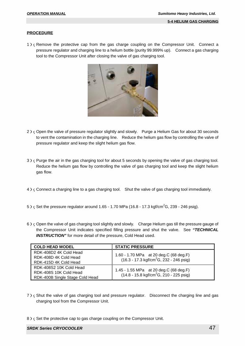
OPERATION MANUAL Sumitomo Heavy Industries, Ltd.
SRDK Series CRYOCOOLER 47
5-4 HELIUM GAS CHARGING
PROCEDURE
1) Remove the protective cap from the gas charge coupling on the Compressor Unit. Connect a
pressure regulator and charging line to a helium bottle (purity 99.999% up). Connect a gas charging
tool to the Compressor Unit after closing the valve of gas charging tool.
2) Open the valve of pressure regulator slightly and slowly. Purge a Helium Gas for about 30 seconds
to vent the contamination in the charging line. Reduce the helium gas flow by controlling the valve of
pressure regulator and keep the slight helium gas flow.
3) Purge the air in the gas charging tool for about 5 seconds by opening the valve of gas charging tool.
Reduce the helium gas flow by controlling the valve of gas charging tool and keep the slight helium
gas flow.
4) Connect a charging line to a gas charging tool. Shut the valve of gas charging tool immediately.
5) Set the pressure regulator around 1.65 - 1.70 MPa (16.8 - 17.3 kgf/cm2G, 239 - 246 psig).
6) Open the valve of gas charging tool slightly and slowly. Charge Helium gas till the pressure gauge of
the Compressor Unit indicates specified filling pressure and shut the valve. See “TECHNICALINSTRUCTION” for more detail of the pressure, Cold Head used.
COLD HEAD MODEL STATIC PRESSURERDK-408D2 4K Cold Head
RDK-408D 4K Cold Head
RDK-415D 4K Cold Head
1.60 - 1.70 MPa at 20 deg.C (68 deg.F)
(16.3 - 17.3 kgf/cm2G, 232 - 246 psig)
RDK-408S2 10K Cold Head
RDK-408S 10K Cold Head
RDK-400B Single Stage Cold Head
1.45 - 1.55 MPa at 20 deg.C (68 deg.F)
(14.8 - 15.8 kgf/cm2G, 210 - 225 psig)
7) Shut the valve of gas charging tool and pressure regulator. Disconnect the charging line and gas
charging tool from the Compressor Unit.
8) Set the protective cap to gas charge coupling on the Compressor Unit.
OPERATION MANUAL Sumitomo Heavy Industries, Ltd.
SRDK Series CRYOCOOLER 48
6 TROUBLE SHOOTING FLOW CHART
6 TROUBLE SHOOTING FLOW CHART
<Warning about electric shock>This cryocooler includes a high-voltage section. Touching it may result in electric shock.
Handle it with extreme care.
Make sure no power is applied to the compressor unit before starting operation when connecting
or disconnecting the cold head power cable. Failing to observe this precaution may result in
electric shock.
Be sure to turn off and Lock Out with OFF position the main power of the customer's power b
connecting or disconnecting the input power cable to the Compressor Unit, and then remove the
input power cable from the main power. Failing to observe this precaution may result in electric
shock.
Pay special attention to its wiring when using the external connector on the compressor unit.
Connecting a jumper wire between Pins No.6 - No.8, No.6 - No.13 and No.6 - No.15 may result
in misoperation in some of safety devices in the equipment, causing electric shock, burn or
malfunction.
Be sure to turn off and Lock Out with OFF position the customer's main power before performing
maintenance work such as replacement of fuses. Failing to observe this precaution may result
in electric shock.
<Warning about explosion, escape of gas>This cryocooler (cold head, compressor unit, compressor adsorber, flex lines) contains a high-
pressure (about 1.62 MPa (16.5 kgf/cm2G, 235 psig)) helium gas sealed in. Hitting the
equipment with a sharp edge or touching it with a pointed object may cause explosion or escape
of gas. Handle the equipment with extreme care.
Do not disassemble the equipment for purposes other than maintenance specified in this
service manual under any circumstances. Disassembling the equipment may result in electric
shock, explosion or escape of gas.
Do not break the vacuum with the low temperature of cold head second stage when removing
the cold head from the vacuum chamber. Breaking the vacuum may result in serious damage,
explosion or escape of gas. Keep the Flex Lines connected and maintain the high vacuum of
the chamber and wait until the cold head second stage temperature rises up to 100K before
removing the cold head.
<Warning about rotating part>If the compressor unit used is the CSA-71A (air cooled, low voltage type), a venting fan is
provided in the exhaust section at the top of the compressor unit. Do not insert foreign
substances from the exhaust port under any circumstances. Failing to observe this precaution
may result in injury or malfunction.
The Adsorber weight is about 11.0kg. When replace the adsorber, be careful of handling so that
it may not get hurt.
WARNING
WARNING
WARNING
WARNING

OPERATION MANUAL Sumitomo Heavy Industries, Ltd.
SRDK Series CRYOCOOLER 49
6 TROUBLE SHOOTING FLOW CHART
<Caution against misoperation>Secure enough space around the compressor unit for heat radiation and maintenance. Failing
to secure enough space may result in misoperation or malfunction. (See the technical
instruction of the compressor unit used, for details.)
If the compressor unit used is the CSA-71A (air cooled, low voltage type), sufficient space is
required for venting. Failing to secure sufficient space may result in misoperation or
malfunction. (See the CSA-71A technical instruction, for details.)
If the compressor unit used is the CSA-71A (air cooled, low voltage type), it should be installed
in a clean environment. Installing it in a dusty environment such as inside a factory will require
frequent cleaning of the cooler fins or may result in misoperation or malfunction.
If the compressor unit used is a water-cooled type (CSW-71C, CSW-71D), use cooling water
with appropriate temperature, flow rate and water quality. Using inappropriate cooling water
may result in misoperation or malfunction. (See the technical instruction of the compressor unit
used, for details.)
The cold head drive switch provided with the compressor unit is only used for maintenance. Be
sure to turn it OFF in normal operation. Using the compressor unit with the cold head drive
switch turned ON may result in misoperation or malfunction.
CAUTION
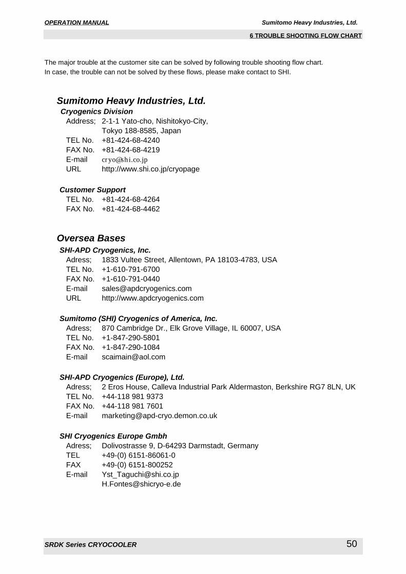
OPERATION MANUAL Sumitomo Heavy Industries, Ltd.
SRDK Series CRYOCOOLER 50
6 TROUBLE SHOOTING FLOW CHART
The major trouble at the customer site can be solved by following trouble shooting flow chart.
In case, the trouble can not be solved by these flows, please make contact to SHI.
Sumitomo Heavy Industries, Ltd. Cryogenics Division
Address; 2-1-1 Yato-cho, Nishitokyo-City,
Tokyo 188-8585, Japan
TEL No. +81-424-68-4240
FAX No. +81-424-68-4219
E-mail [email protected] http://www.shi.co.jp/cryopage
Customer SupportTEL No. +81-424-68-4264
FAX No. +81-424-68-4462
Oversea Bases SHI-APD Cryogenics, Inc.
Adress; 1833 Vultee Street, Allentown, PA 18103-4783, USA
TEL No. +1-610-791-6700
FAX No. +1-610-791-0440
E-mail [email protected]
URL http://www.apdcryogenics.com
Sumitomo (SHI) Cryogenics of America, Inc.Adress; 870 Cambridge Dr., Elk Grove Village, IL 60007, USA
TEL No. +1-847-290-5801
FAX No. +1-847-290-1084
E-mail [email protected]
SHI-APD Cryogenics (Europe), Ltd.Adress; 2 Eros House, Calleva Industrial Park Aldermaston, Berkshire RG7 8LN, UK
TEL No. +44-118 981 9373
FAX No. +44-118 981 7601
E-mail [email protected]
SHI Cryogenics Europe GmbhAdress; Dolivostrasse 9, D-64293 Darmstadt, Germany
TEL +49-(0) 6151-86061-0
FAX +49-(0) 6151-800252
E-mail [email protected]
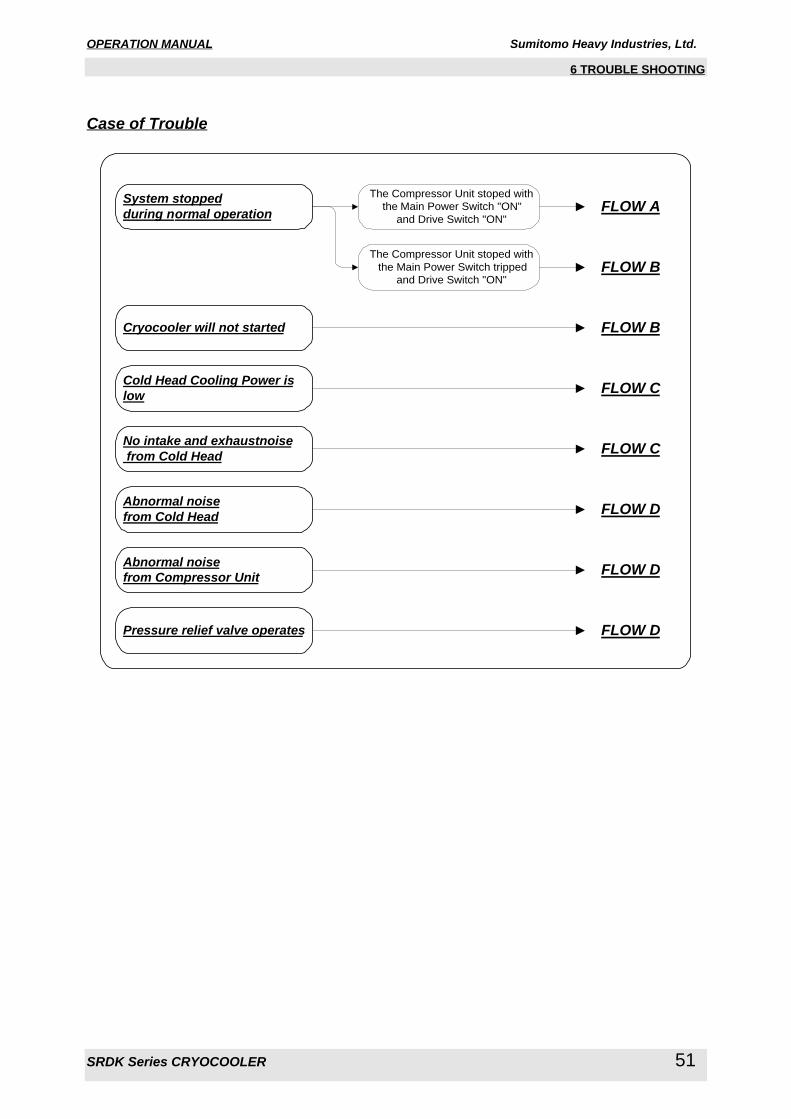
OPERATION MANUAL Sumitomo Heavy Industries, Ltd.
SRDK Series CRYOCOOLER 51
6 TROUBLE SHOOTING
Case of Trouble
System stoppedduring normal operation
The Compressor Unit stoped with
the Main Power Switch "ON"
and Drive Switch "ON"
The Compressor Unit stoped with
the Main Power Switch tripped
and Drive Switch "ON"
Cryocooler will not started
Cold Head Cooling Power islow
FLOW A
FLOW B
FLOW B
FLOW C
FLOW C
FLOW D
FLOW D
FLOW D
No intake and exhaustnoise from Cold Head
Abnormal noisefrom Cold Head
Abnormal noisefrom Compressor Unit
Pressure relief valve operates
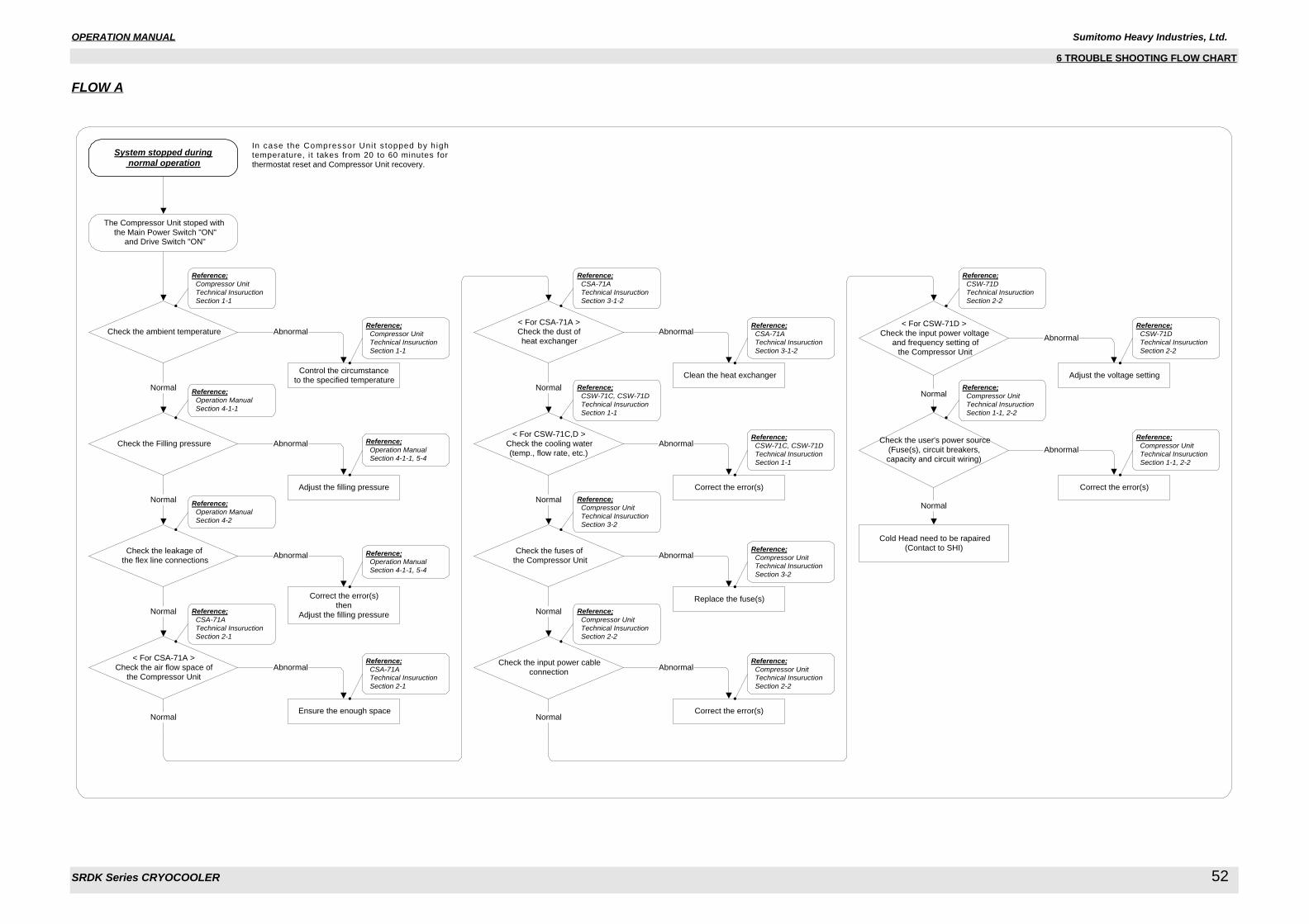
OPERATION MANUAL Sumitomo Heavy Industries, Ltd.
SRDK Series CRYOCOOLER 52
6 TROUBLE SHOOTING FLOW CHART
FLOW A
In case the Compressor Uni t s topped by h ightemperature, i t takes from 20 to 60 minutes for
thermostat reset and Compressor Unit recovery.
System stopped during normal operation
Normal
Check the Filling pressure Abnormal
Adjust the filling pressure
The Compressor Unit stoped with
the Main Power Switch "ON" and Drive Switch "ON"
Check the input power cable
connection
Correct the error(s)
Abnormal
Check the fuses of
the Compressor UnitAbnormal
Replace the fuse(s)
Normal
< For CSA-71A >
Check the air flow space of
the Compressor Unit
Abnormal
Ensure the enough space
Normal
< For CSW-71C,D >
Check the cooling water
(temp., flow rate, etc.)
Abnormal
Correct the error(s)
Check the ambient temperature Abnormal
Control the circumstance
to the specified temperatureNormal
Normal
Cold Head need to be rapaired
(Contact to SHI)
< For CSW-71D >
Check the input power voltage and frequency setting of
the Compressor Unit
Normal
Abnormal
Adjust the voltage setting
Check the user's power source
(Fuse(s), circuit breakers,
capacity and circuit wiring)
Abnormal
Correct the error(s)
Normal
Check the leakage of
the flex line connectionsAbnormal
Correct the error(s)
then
Adjust the filling pressureNormal
Reference; Compressor Unit Technical Insuruction Section 1-1
Reference; Operation Manual Section 4-1-1
Reference; Operation Manual Section 4-2
Reference; Compressor Unit Technical Insuruction Section 1-1
Reference; Operation Manual Section 4-1-1, 5-4
Reference; Operation Manual Section 4-1-1, 5-4
Reference; CSA-71A Technical Insuruction Section 2-1
Reference; CSA-71A Technical Insuruction Section 2-1
Normal
Normal
< For CSA-71A >Check the dust of
heat exchanger
Abnormal
Clean the heat exchanger
Reference; CSA-71A Technical Insuruction Section 3-1-2
Reference; CSA-71A Technical Insuruction Section 3-1-2
Reference; CSW-71C, CSW-71D Technical Insuruction Section 1-1
Reference; CSW-71C, CSW-71D Technical Insuruction Section 1-1
Reference; Compressor Unit Technical Insuruction Section 3-2
Reference; Compressor Unit Technical Insuruction Section 3-2
Reference; Compressor Unit Technical Insuruction Section 2-2
Reference; Compressor Unit Technical Insuruction Section 2-2
Reference; CSW-71D Technical Insuruction Section 2-2
Reference; CSW-71D Technical Insuruction Section 2-2
Reference; Compressor Unit Technical Insuruction Section 1-1, 2-2
Reference; Compressor Unit Technical Insuruction Section 1-1, 2-2
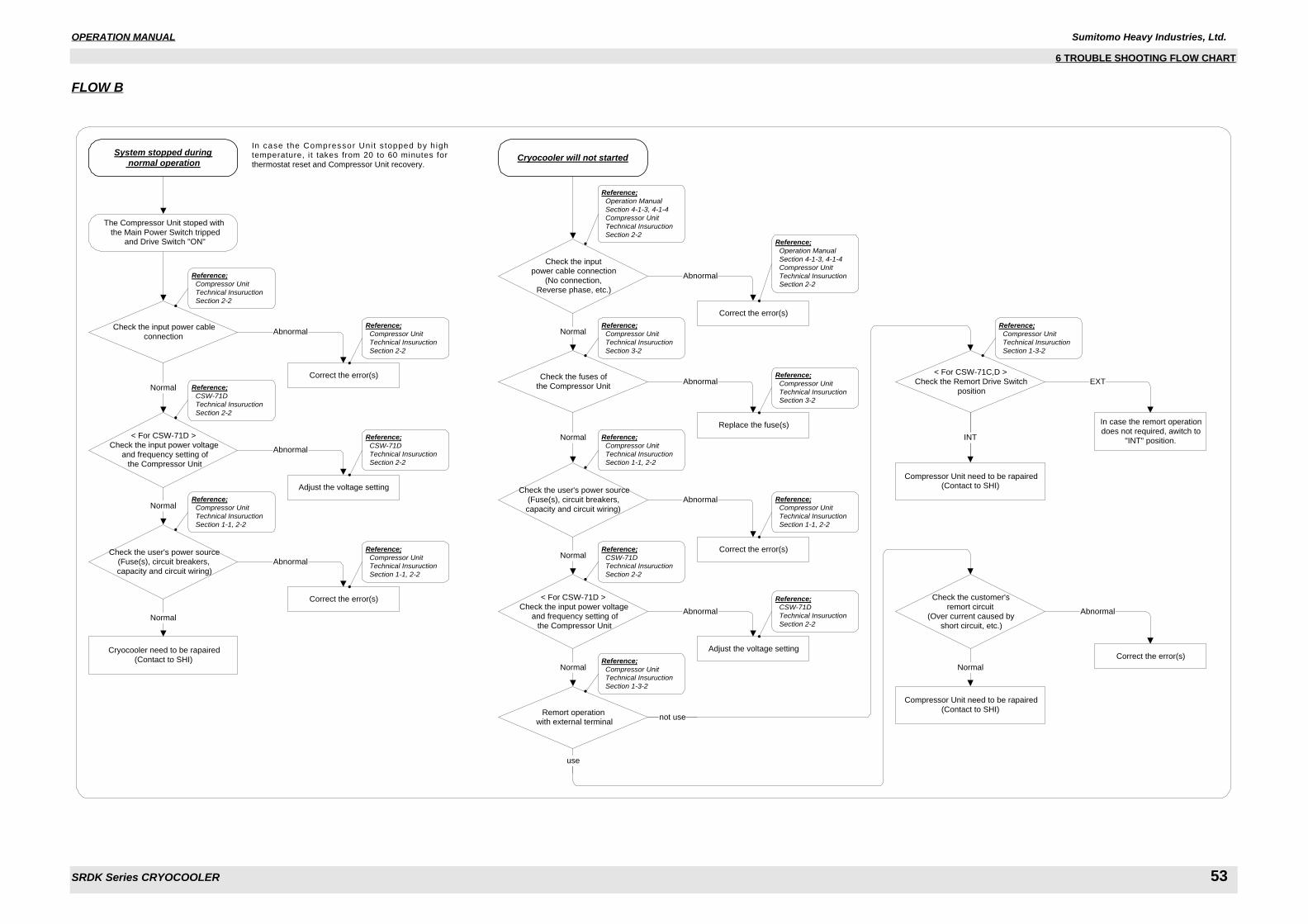
OPERATION MANUAL Sumitomo Heavy Industries, Ltd.
SRDK Series CRYOCOOLER 53
6 TROUBLE SHOOTING FLOW CHART
FLOW B
System stopped during normal operation
Cryocooler need to be rapaired
(Contact to SHI)
Check the input power cable
connection
Correct the error(s)
< For CSW-71D >
Check the input power voltage
and frequency setting of
the Compressor Unit
Normal
Abnormal
Adjust the voltage setting
Check the user's power source
(Fuse(s), circuit breakers,
capacity and circuit wiring)
Abnormal
Correct the error(s)
Normal
Normal
Abnormal
Reference; Compressor Unit Technical Insuruction Section 2-2
Reference; Compressor Unit Technical Insuruction Section 2-2
Reference; CSW-71D Technical Insuruction Section 2-2
Reference; CSW-71D Technical Insuruction Section 2-2
Reference; Compressor Unit Technical Insuruction Section 1-1, 2-2
Reference; Compressor Unit Technical Insuruction Section 1-1, 2-2
The Compressor Unit stoped with
the Main Power Switch tripped and Drive Switch "ON"
Cryocooler will not started
Check the inputpower cable connection
(No connection,
Reverse phase, etc.)
Correct the error(s)
Abnormal
Normal
< For CSW-71D >
Check the input power voltage
and frequency setting of
the Compressor Unit
Abnormal
Adjust the voltage setting
Check the user's power source
(Fuse(s), circuit breakers,
capacity and circuit wiring)
Abnormal
Correct the error(s)Normal
Check the fuses of
the Compressor UnitAbnormal
Replace the fuse(s)
Normal
Compressor Unit need to be rapaired
(Contact to SHI)
< For CSW-71C,D >
Check the Remort Drive Switch
position
EXT
In case the remort operation
does not required, awitch to
"INT" position.
Remort operation with external terminal
Check the customer's
remort circuit
(Over current caused by
short circuit, etc.)
Normal
Abnormal
Correct the error(s)
INT
Normal
Reference; Operation Manual Section 4-1-3, 4-1-4 Compressor Unit Technical Insuruction Section 2-2
Reference; Operation Manual Section 4-1-3, 4-1-4 Compressor Unit Technical Insuruction Section 2-2
Reference; Compressor Unit Technical Insuruction Section 3-2
Reference; Compressor Unit Technical Insuruction Section 3-2
Reference; Compressor Unit Technical Insuruction Section 1-1, 2-2
Reference; Compressor Unit Technical Insuruction Section 1-1, 2-2
Reference; CSW-71D Technical Insuruction Section 2-2
Reference; CSW-71D Technical Insuruction Section 2-2
Reference; Compressor Unit Technical Insuruction Section 1-3-2
Compressor Unit need to be rapaired(Contact to SHI)
not use
Reference; Compressor Unit Technical Insuruction Section 1-3-2
In case the Compressor Uni t s topped by h ightemperature, i t takes from 20 to 60 minutes for
thermostat reset and Compressor Unit recovery.
use
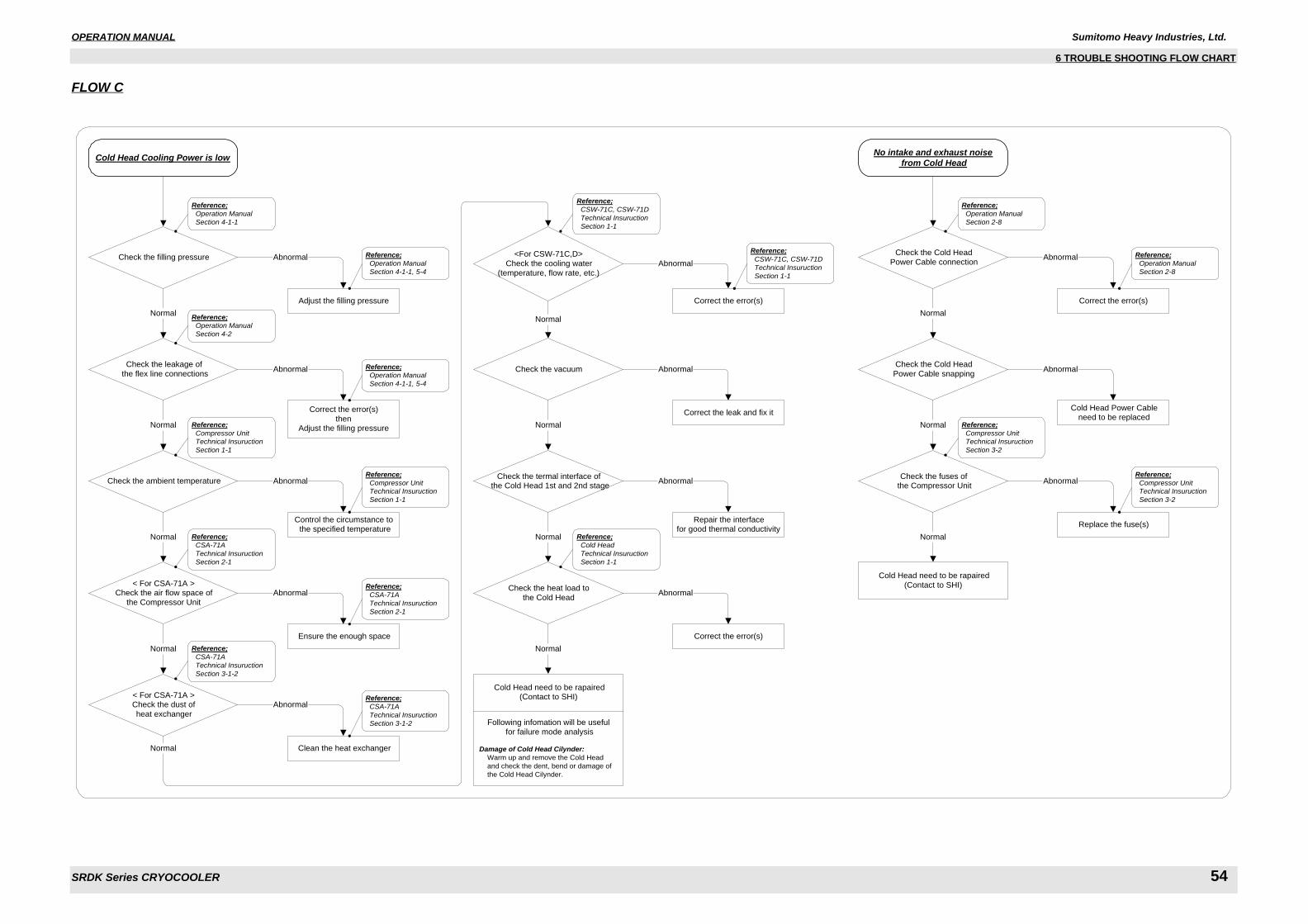
OPERATION MANUAL Sumitomo Heavy Industries, Ltd.
SRDK Series CRYOCOOLER 54
6 TROUBLE SHOOTING FLOW CHART
FLOW C
Cold Head Cooling Power is low
Check the leakage of
the flex line connectionsAbnormal
Correct the error(s)
thenAdjust the filling pressureNormal
No intake and exhaust noise from Cold Head
Check the ambient temperature
Control the circumstance to the specified temperature
Abnormal
Normal
Check the Cold Head
Power Cable connection
Correct the error(s)
Abnormal
Normal
Cold Head need to be rapaired
(Contact to SHI)
Check the Cold Head
Power Cable snapping
Normal
Abnormal
Cold Head Power Cableneed to be replaced
Check the fuses of the Compressor Unit
Abnormal
Replace the fuse(s)
Normal
Normal
Check the filling pressure Abnormal
Adjust the filling pressure
Normal
<For CSW-71C,D>
Check the cooling water
(temperature, flow rate, etc.)
Abnormal
Correct the error(s)
Normal
< For CSA-71A >Check the air flow space of
the Compressor Unit
Abnormal
Ensure the enough space
Check the termal interface of the Cold Head 1st and 2nd stage
Abnormal
Repair the interfacefor good thermal conductivity
Normal
Check the vacuum
Correct the leak and fix it
Abnormal
Normal
Check the heat load to
the Cold Head
Correct the error(s)
Abnormal
Normal
Cold Head need to be rapaired(Contact to SHI)
Following infomation will be useful
for failure mode analysis
Damage of Cold Head Cilynder: Warm up and remove the Cold Head
and check the dent, bend or damage of
the Cold Head Cilynder.
Reference; Compressor Unit Technical Insuruction Section 1-1
Reference; Compressor Unit Technical Insuruction Section 1-1
Reference; Operation Manual Section 4-1-1
Reference; Operation Manual Section 4-1-1, 5-4
Reference; Operation Manual Section 4-2
Reference; Operation Manual Section 4-1-1, 5-4
Reference; CSA-71A Technical Insuruction Section 2-1
Reference; CSA-71A Technical Insuruction Section 2-1
< For CSA-71A >Check the dust of
heat exchanger
Abnormal
Clean the heat exchanger
Reference; CSA-71A Technical Insuruction Section 3-1-2
Reference; CSA-71A Technical Insuruction Section 3-1-2
Normal
Reference; Cold Head Technical Insuruction Section 1-1
Reference; CSW-71C, CSW-71D Technical Insuruction Section 1-1
Reference; CSW-71C, CSW-71D Technical Insuruction Section 1-1
Reference; Operation Manual Section 2-8
Reference; Operation Manual Section 2-8
Reference; Compressor Unit Technical Insuruction Section 3-2
Reference; Compressor Unit Technical Insuruction Section 3-2
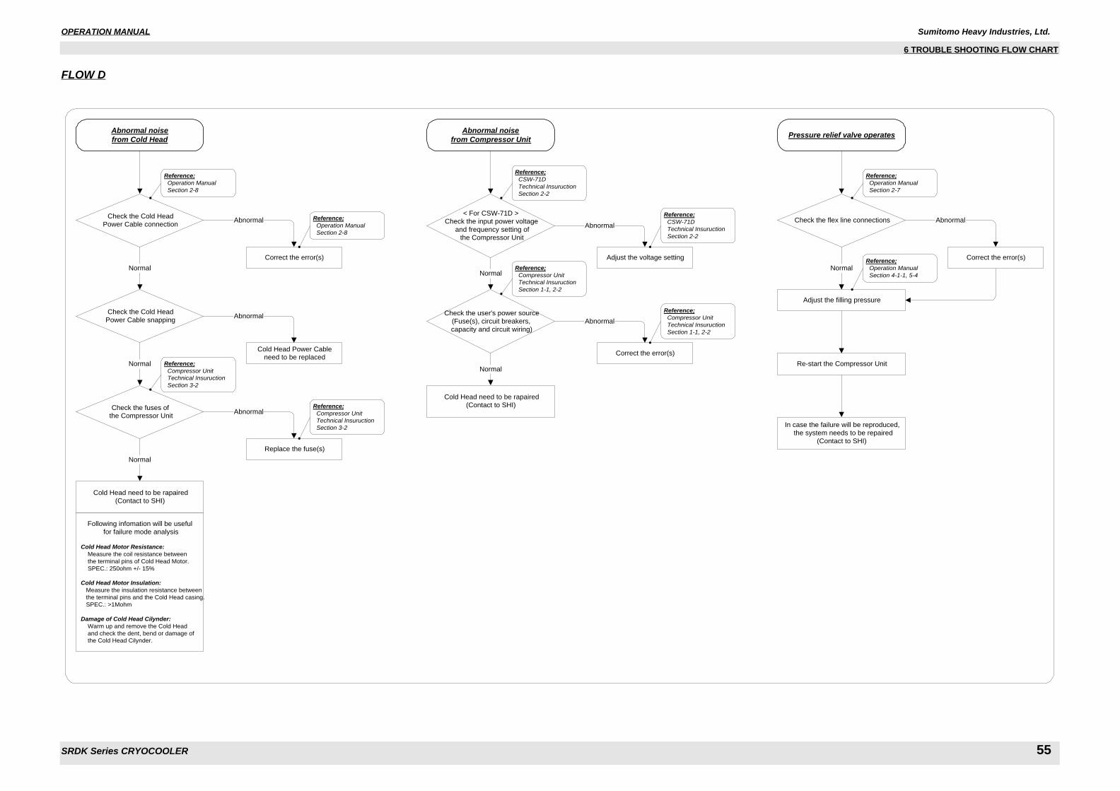
OPERATION MANUAL Sumitomo Heavy Industries, Ltd.
SRDK Series CRYOCOOLER 55
6 TROUBLE SHOOTING FLOW CHART
FLOW D
Cold Head need to be rapaired
(Contact to SHI)
Following infomation will be useful
for failure mode analysis
Cold Head Motor Resistance: Measure the coil resistance between
the terminal pins of Cold Head Motor.
SPEC.: 250ohm +/- 15%
Cold Head Motor Insulation: Measure the insulation resistance between
the terminal pins and the Cold Head casing.
SPEC.: >1Mohm
Damage of Cold Head Cilynder: Warm up and remove the Cold Head
and check the dent, bend or damage of
the Cold Head Cilynder.
Abnormal noisefrom Cold Head
Check the Cold Head
Power Cable connection
Correct the error(s)
Abnormal
Normal
Check the Cold Head
Power Cable snapping
Normal
Abnormal
Cold Head Power Cableneed to be replaced
Check the fuses of the Compressor Unit
Abnormal
Replace the fuse(s)
Normal
Reference; Operation Manual Section 2-8
Reference; Operation Manual Section 2-8
Reference; Compressor Unit Technical Insuruction Section 3-2
Reference; Compressor Unit Technical Insuruction Section 3-2
Abnormal noisefrom Compressor Unit
Cold Head need to be rapaired
(Contact to SHI)
Pressure relief valve operates
Normal
Adjust the filling pressure
In case the failure will be reproduced,
the system needs to be repaired
(Contact to SHI)
Re-start the Compressor Unit
< For CSW-71D >
Check the input power voltage
and frequency setting of
the Compressor Unit
Normal
Abnormal
Adjust the voltage setting
Check the user's power source
(Fuse(s), circuit breakers,
capacity and circuit wiring)
Abnormal
Correct the error(s)
Normal
Reference; CSW-71D Technical Insuruction Section 2-2
Reference; CSW-71D Technical Insuruction Section 2-2
Reference; Compressor Unit Technical Insuruction Section 1-1, 2-2
Reference; Compressor Unit Technical Insuruction Section 1-1, 2-2
Check the flex line connections Abnormal
Correct the error(s)
Reference; Operation Manual Section 2-7
Reference; Operation Manual Section 4-1-1, 5-4
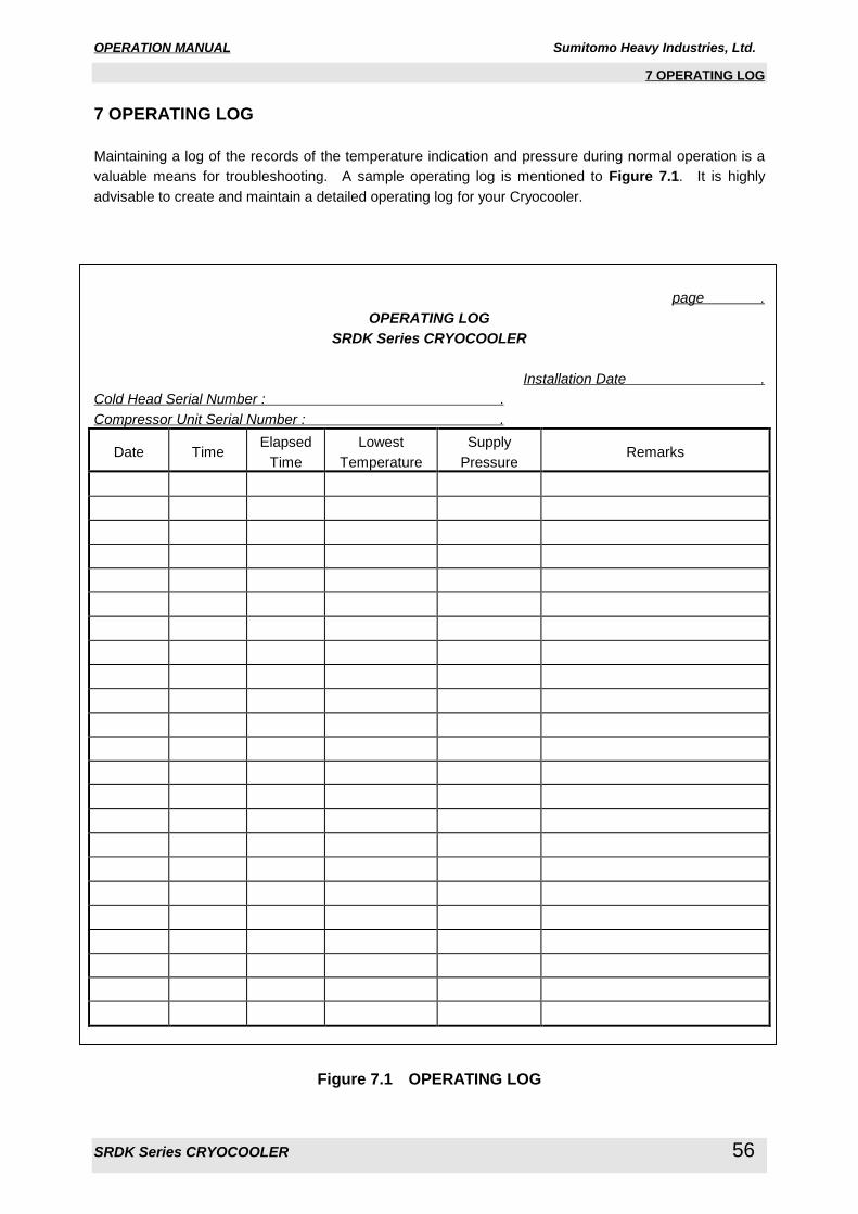
OPERATION MANUAL Sumitomo Heavy Industries, Ltd.
SRDK Series CRYOCOOLER 56
7 OPERATING LOG
7 OPERATING LOG
Maintaining a log of the records of the temperature indication and pressure during normal operation is a
valuable means for troubleshooting. A sample operating log is mentioned to Figure 7.1. It is highly
advisable to create and maintain a detailed operating log for your Cryocooler.
page .OPERATING LOG
SRDK Series CRYOCOOLER
Installation Date .Cold Head Serial Number : .Compressor Unit Serial Number : .
Date TimeElapsed
Time
Lowest
Temperature
Supply
PressureRemarks
Figure 7.1 OPERATING LOG
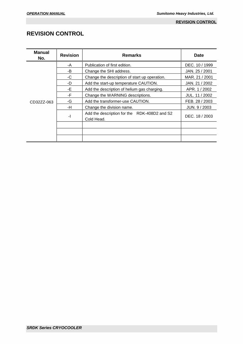
OPERATION MANUAL Sumitomo Heavy Industries, Ltd.
SRDK Series CRYOCOOLER
REVISION CONTROL
REVISION CONTROL
ManualNo. Revision Remarks Date
-A Publication of first edition. DEC. 10 / 1999
-B Change the SHI address. JAN. 25 / 2001
-C Change the description of start up operation. MAR. 21 / 2001
-D Add the start-up temperature CAUTION. JAN. 21 / 2002
-E Add the description of helium gas charging. APR. 1 / 2002
-F Change the WARNING descriptions. JUL. 11 / 2002
-G Add the transformer-use CAUTION. FEB. 28 / 2003
-H Change the division name. JUN. 9 / 2003
-I Add the description for the RDK-408D2 and S2
Cold Head.DEC. 18 / 2003
CD32ZZ-063