operation manual for the authorized specialist oil burner ... 6... · operation manual for the...
TRANSCRIPT
Operation Manualfor the authorized specialist
Oil BurnerEK 6../7../8../9.. S-R
01/2002 102.881.0844

2
Inhalt
Overview Table of Contens ................................................................................................... 2Overview Important Information ............................................................................................ 3
Sectional Drawing ................................................................................................. 4Technical Data ...................................................................................................... 5Technical Data ...................................................................................................... 6Dimensioned Drawings ....................................................................................... 10
Operation Start-up ModeOil Operating ModeGeneral Safety Functions .................................................................................... 13Fuel-air Compound ControlHydraulic Diagram ............................................................................................... 15
Start-up Burner Head Settings .......................................................................................... 16Installation Mounting to Boiler
Electrical ConnectionPresetting ............................................................................................................ 19
Installation Boiler lining .......................................................................................................... 20Installation Oil Supply ............................................................................................................ 21Installation Oil Supply ............................................................................................................ 22
Viscosity as a Function of Oil Temperature ........................................................ 23Oil Pump ............................................................................................................. 24Pump Output Diagram ........................................................................................ 26Electric oil pre-heater .......................................................................................... 27Thermostat Setting .............................................................................................. 28 ............................................................................................................................ 28Return Nozzle Rod MAT ..................................................................................... 29Nozzle Output Curves ......................................................................................... 30
Burner Operation Oil Burner OperationHydraulic Diagram ............................................................................................... 32Checking Procedure ............................................................................................ 33
Start-up Pressure Control Valve in Feed Line .................................................................. 34Output Pressure Control Valve in Return Line .................................................... 35Oil/Air Flow Rate Adjustment 36
Adjusting Instructions Electrical ActuatorLimit Switch Setting ............................................................................................. 37
Start-up Flushing and Oil Feed Start Thermostat ATH 22 ................................................ 38Adjusting Instructions Oil Pressure Switch (Option)
Air Pressure Switch ............................................................................................. 39Operation Automatic Furnace Controller LFL 1... / LGK 16...
Regulator KS 92 .................................................................................................. 40Adjusting Instructions Flame Monitor
Sensor Current Measurement ............................................................................. 41Servicing Instructions Burner Maintenance
Fan Impeller ........................................................................................................ 42Exhaust Gas Test ................................................................................................ 43Trouble Shooting Instructions ............................................................................. 44
Overview
Table of Contens
3
Overview
Important Information
General information
Installation and start-up of the burner are the responsibility of qualified per-sonnel, and they are responsible for correct installation.
Qualified personnel are specialists who are familiar with the erection, instal-lation, setting-up and start-up of the bur-ner.
These specialists
- have been trained in the handling of fuels (combustible liquids) accor-ding to the valid and applicable gui-delines and regulations.
- are authorized and trained to test and install electric circuits and elec-trical equipment in accordance with the technical safety standards.
To ensure safe, environmentally friendly and energy-saving operation the follo-wing standards, among others, are to be followed:
DIN 4755 Oil fired furnaces in heating plants
EN 267 Vaporizing oil burners
DIN 4789 Connecting vaporizing oil and gas bur-ners with blowers to heat generators
VDE 01 16 (pr EN 50 156) Electrical furnace equipment
Installation The burner must be installed and set up in accordance with the instructions sup-plied by the manufacturer. The instruc-tions provided by the boiler manufacturer must also be adhered to.
Starting up The initial start-up of the furnace must be carried out by the erector, manufac-turer or other specialist authorized by them.
Product descriptionThe burners of types EK 6.../ EK 7.../EK 8.../ EK 9...S-R are oil burners for the combustion of heavy fuel oil accor-ding DIN 51603-3, all equipped to the EN 267 safety standard.The burners are equipped with combu-stion air fan and air pressure switch with test key, oil pressure atomizer with oil high-pressure pump, nozzle rod, return nozzle and hydraulic oil system (valves, pressure switch, piping, etc.), gas igni-tion burner (option), electrical igniter and mechanical compound control system.
Testing and maintenance The operator must check or have the plant checked and/or serviced at least once every year. The combustion values must be checked after every maintenance action.
Guarantee Damages arising from the following are excluded from the guarantee:
• Improper use or operation • Faulty installation or repair work on
the part of the buyer or third parties, including the acquisition of parts not supplied by the manufacturer
• Operation of the plant under excess pressure or outside the manufactu-rer's performance data or inappro-priate oil supply
• Use of unsuitable fuels

4
Sectional Drawing
1 Pump motor2 Blower motor4 Fan impeller5 Output Pressure Control Valve7 Compound controller8 Actuator9 Return nozzle rod10 Ignition transformer11 Ignition electrodes12 Flame sensor13 Pilot burner14 Burner housing15 Air box16 Inspection glass19 Oil pump20 Oil nozzle21 Baffle plate22 Flame tube23 Cable inlets28 Pre-heater29 Electrical connection and
temperature controller
Key to types
Example: EK 6.300 S-R
EK Elco Klöckner6. Size300 Load index
(x10 = approx. burner output in kW)
S Heavy oilR Mechanical compound control

5
Technical Data SheetHeavy Oil Burner
EK 6.200 S-R
Technical Data
Burner output
Fuel flow rate
Operating mode
Type of fuel
Burner control box
Flame sensor
Fan motor
Pump unit
Gear output
Pressure
Nozzle rod
Nozzle
Oil hoses / External connection
Actuator
Ignition transformer
Ignition burner
Weight
Operating range EK 6.200 S-R
0
2
4
6
8
10
12
14
16
18
20
0 500 1000 1500 2000 2500
6.200 S
Q Burner output [kW]F
Air temperature 20°C, test values according to EN 267 (DIN 4787) at 171 m above sea level
Pre-heater
Pre
ssu
re in
co
mb
ust
ion
ch
amb
er [
mb
ar]
6.200 S-R
700 - 1999 kW
63 - 180 kg/h
fully modulating
Heavy fuel oil
LFL 1.3 / LFL 1.6 / LGK 16
QRA 2 / QRA 2 / QRA 53
400 / 690 V, 50 Hz3,0 kW, 6,6 A, 2800 min-¹
SMG 1527 - 0,75 kW
540 l/h
30 bar
MAT-DG
MK 27
DN 13x1300
SQM 10/11
ZA20 140 / ZM20-14
ZB 12
220 kg≈
3x230/400 V1x12 kW
F
0 kg≈
Art.No.: 102.881.646601/02
Technical Data
EK 6.200 S-R
6
Technical Data SheetHeavy Oil Burner
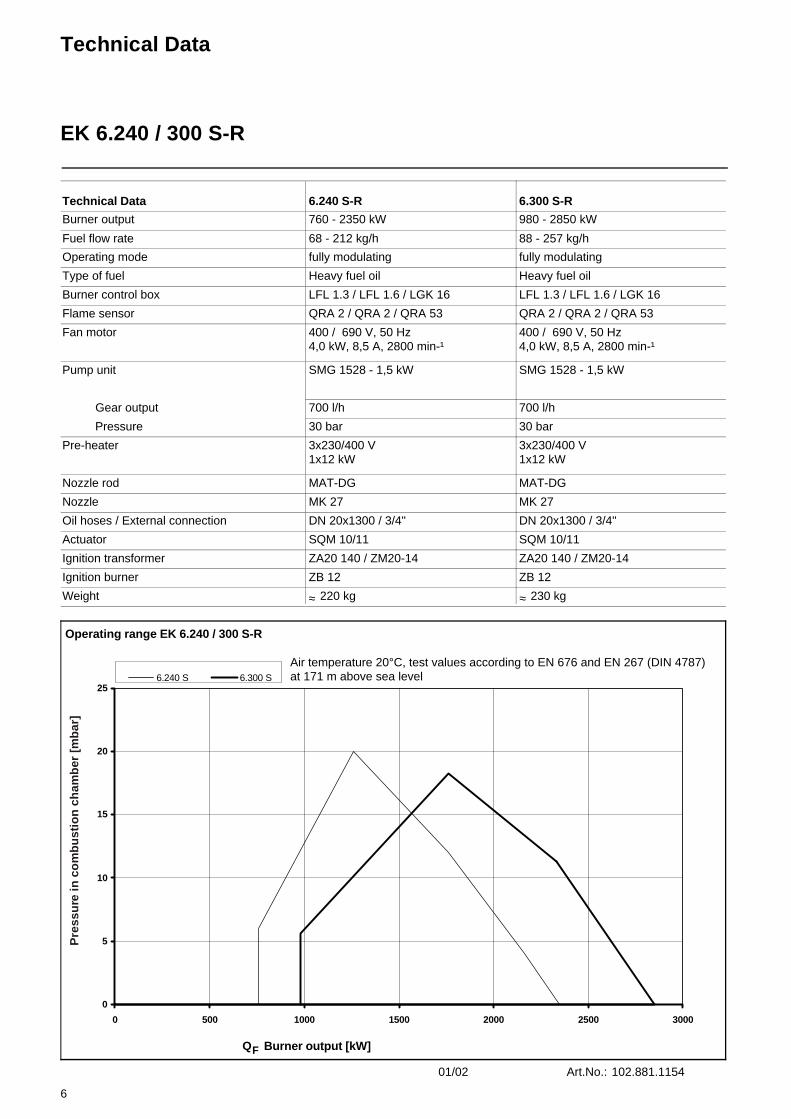
EK 6.240 / 300 S-R
Technical Data
Burner output
Fuel flow rate
Operating mode
Type of fuel
Burner control box
Flame sensor
Fan motor
Pump unit
Gear output
Pressure
Nozzle rod
Nozzle
Oil hoses / External connection
Actuator
Ignition transformer
Ignition burner
Weight
Operating range EK 6.240 / 300 S-R
0
5
10
15
20
25
0 500 1000 1500 2000 2500 3000
6.240 S 6.300 S
Q Burner output [kW]F
Air temperature 20°C, test values according to EN 676 and EN 267 (DIN 4787) at 171 m above sea level
Pre-heater
Pre
ssu
re in
co
mb
ust
ion
ch
amb
er [
mb
ar]
6.240 S-R
760 - 2350 kW
68 - 212 kg/h
fully modulating
Heavy fuel oil
LFL 1.3 / LFL 1.6 / LGK 16
QRA 2 / QRA 2 / QRA 53
400 / 690 V, 50 Hz4,0 kW, 8,5 A, 2800 min-¹
SMG 1528 - 1,5 kW
700 l/h
30 bar
MAT-DG
MK 27
DN 20x1300 / 3/4"
SQM 10/11
ZA20 140 / ZM20-14
ZB 12
220 kg≈
3x230/400 V1x12 kW
6.300 S-R
980 - 2850 kW
88 - 257 kg/h
fully modulating
Heavy fuel oil
LFL 1.3 / LFL 1.6 / LGK 16
QRA 2 / QRA 2 / QRA 53
400 / 690 V, 50 Hz4,0 kW, 8,5 A, 2800 min-¹
SMG 1528 - 1,5 kW
700 l/h
30 bar
MAT-DG
MK 27
DN 20x1300 / 3/4"
SQM 10/11
ZA20 140 / ZM20-14
ZB 12
230 kg≈
3x230/400 V1x12 kW
Art.No.: 102.881.115401/02
Technical Data
EK 6.240 / 300 S-R

7
Technical Data SheetHeavy Oil Burner
EK 7... S-R
Technical Data
Burner output
Fuel flow rate
Operating mode
Type of fuel
Burner control box
Flame sensor
Fan motor
Pump unit
Gear output
Pressure
Nozzle rod
Nozzle
Oil hoses / External connection
Actuator
Ignition transformer
Ignition burner
Weight
Operating range EK 7... S-R
0
5
10
15
20
25
30
0 1000 2000 3000 4000 5000 6000
7.350 S 7.450 S
Q Burner output [kW]F
Air temperature 20°C, test values according to EN 267 (DIN 4787) at 171 m above sea level
Pre-heater
Pre
ssu
re in
co
mb
ust
ion
ch
amb
er [
mb
ar]
7.350 S-R
1200 - 4153 kW
107 - 375 kg/h
fully modulating
Heavy fuel oil
LFL 1.3 / LFL 1.6 / LGK 16
QRA 2 / QRA 2 / QRA 53
400 / 690 V, 50 Hz5,5 kW, 11,7 A, 2800 min-¹
SMG 1529 - 2,2 kW
1200 l/h
30 bar
MAT-DG
MK 27
DN 20x1300 / 3/4"
SQM 10/11
ZA20 140 / ZM20-14
ZB 2
350 kg≈
3x230/400 V1x20 kW
7.450 S-R
1300 - 4700 kW
116 - 424 kg/h
fully modulating
Heavy fuel oil
LFL 1.3 / LFL 1.6 / LGK 16
QRA 2 / QRA 2 / QRA 53
400 / 690 V, 50 Hz7,5 kW, 15,5 A, 2800 min-¹
SMG 1529 - 2,2 kW
1200 l/h
30 bar
MAT-DG
MK 27
DN 20x1300 / 3/4"
SQM 10/11
ZA20 140 / ZM20-14
ZB 2
350 kg≈
3x230/400 V1x20 kW
Art.No.: 102.881.085501/02
Technical Data
EK 7... S-R

8
Technical Data SheetHeavy Oil Burner
EK 8... S-R
Technical Data
Burner output
Fuel flow rate
Operating mode
Type of fuel
Burner control box
Flame sensor
Fan motor
Pump unit
Gear output
Pressure
Nozzle rod
Nozzle
Oil hoses / External connection
Actuator
Ignition transformer
Ignition burner
Weight
Operating range EK 8... S-R
0
5
10
15
20
25
0 1000 2000 3000 4000 5000 6000 7000 8000
8.550 S 8.700 S
Q Burner output [kW]F
Air temperature 20°C, test values according to EN 267 (DIN 4787) at 171 m above sea level
Pre-heater
Pre
ssu
re in
co
mb
ust
ion
ch
amb
er [
mb
ar]
8.550 S-R
1647 - 5581 kW
150 - 500 kg/h
fully modulating
Heavy fuel oil
LFL 1.3 / LFL 1.6 / LGK 16
QRA 2 / QRA 2 / QRA 53
400 / 690 V, 50 Hz11 kW, 22,5 A, 2800 min-¹
SMG 1530 - 3,0 kW
1700 l/h
30 bar
MAT-DG
MK 27
DN 25x1300 / 1"
SQM 10/11
ZA20 140 / ZM20-14
ZB 2
410 kg≈
3x230/400 V2x12 kW
8.700 S-R
1718 - 6900 kW
154 - 600 kg/h
fully modulating
Heavy fuel oil
LFL 1.3 / LFL 1.6 / LGK 16
QRA 2 / QRA 2 / QRA 53
400 / 690 V, 50 Hz15 kW, 30,0 A, 2800 min-¹
SMG 1530 - 3,0 kW
1700 l/h
30 bar
MAT-DG
MK 27
DN 25x1300 / 1"
SQM 20/21
ZA20 140 / ZM20-14
ZB 2
430 kg≈
3x230/400 V2x12 kW
Art.No.: 102.867.868801/02
Technical Data
EK 8... S-R

9
Technical Data SheetHeavy Oil Burner
EK 9... S-R
Technical Data
Burner output
Fuel flow rate
Operating mode
Type of fuel
Burner control box
Flame sensor
Fan motor
Pump unit
Gear output
Pressure
Nozzle rod
Nozzle
Oil hoses / External connection
Actuator
Ignition transformer
Ignition burner
Weight
Operating range EK 9... S-R
0
5
10
15
20
25
30
35
0 2000 4000 6000 8000 10000 12000
9.850 S 9.1000 S
Q Burner output [kW]F
Air temperature 20°C, test values according to EN 267 (DIN 4787) at 171 m above sea level
Pre-heater
Pre
ssu
re in
co
mb
ust
ion
ch
amb
er [
mb
ar]
9. 850 S-R
2210 - 7845 kW
200 - 710 kg/h
fully modulating
Heavy fuel oil
LFL 1.3 / LFL 1.6 / LGK 16
QRA 2 / QRA 2 / QRA 53
400 / 690 V, 50 Hz18,5 kW, 35,0 A, 2800 min-¹
SMG 1531 - 4,0 kW
2700 l/h
30 bar
MAT-DG
MK 27
DN 25x1300 / 1"
SQM 20/21
ZA20 140 / ZM20-14
ZB 2
820 kg≈
3x230/400 V2x20 kW
9.1000 S-R
2850 - 10276 kW
238 - 930 kg/h
fully modulating
Heavy fuel oil
LFL 1.3 / LFL 1.6 / LGK 16
QRA 2 / QRA 2 / QRA 53
400 / 690 V, 50 Hz22 kW, 42,5 A, 2800 min-¹
SMG 1531 - 4,0 kW
2700 l/h
30 bar
MAT-DG
MK 27
DN 25x1300 / 1"
SQM 20/21
ZA20 140 / ZM20-14
ZB 2
840 kg≈
3x230/400 V2x20 kW
Art.No.: 102.867.869901/02
Technical Data
EK 9... S-R

10
Overview
Dimensioned DrawingsEK 6... S-R
EK 6.200 S-R
Dimensions in boiler connection plate
EK 6.240/300 S-R
Dimensions in boiler connection plate

11
Overview
Dimensioned DrawingsEK 7... / 8... S-R
EK 7.350/450 S-R
Dimensions in boiler connection plate
Type
EK 8.550/700 S-R
Dimensions in boiler connection plate
Type

12
Overview
Dimensioned DrawingsEK 9... S-R
EK 9.850/1000 S-R
Dimensions in boiler connection plateType

13
Operation
Start-up ModeOil Operating ModeGeneral Safety Functions
Oil start-up modeAfter the heavy-oil burner has been tur-ned on the pre-heater will be started. The heavy oil will be heated to a tempe-rature between 80°C and 140°C depen-ding on viscosity. The electric heat-tracing system and the pump pre-heater will be turned on. After the pre-heating phase the oil is pumped through the oil lines and the flushing valve until the desired temperature has been reached. After the selected oil temperature has been reached the start-up program will be turned on.
The automatic furnace controller will control and monitor the starting pro-cess. The electric actuator will open the closed air damper to its full-load position so that the burner will ventilate the fur-nace and the exhaust hoods with the specified air rate. Shortly after the pre-ventilation process has been started the lack-of-air cut-out must change over to operating position within a certain time, i.e. the minimum air pressure setting must be reached and maintained until the burner is turned off. At the end of the specified pre-ventilation time the air damper will be moved into its partial-
load position. The built in gas pilot burner will be igni-ted and after the preignition time the ignition of the main flame will take place.The system may also be designed for ignition by direct electrical igniter.The solenoid valves will open and thus allow the pressurized oil to flow to the nozzle and to the return line. The oil will be atomized, mixed with the combustion air and ignited. A safety period is provi-ded to allow the flame to develop a pro-per and steady pattern. On the termination of the safety period a flame signal must have been received by the automatic furnace controller via the flame monitor and remain on until the regular shut-off. The start-up program of the burner has now been completed.
Oil operating modeAfter the flame has developed the load regulator will be enabled which brings the burner into its operating position. The load regulator will now control the burner automatically between its partial-load and full-load stages.Depending on the heat demand, the electric actuator of the mechanical com-
pound control system will be fed with the OPEN or CLOSE signal via the regulator and thus increase or decrease the oil and air flow rates.This compound control system will vary the positions of the oil control valve and air damper and thus regulate the oil flow rate in conjunction with the air flow rate. The burner can either be controlled in two-stage sliding mode or, if a respec-tive controller is provided, in stepless control mode. The stepless control will allow the bur-ner to be operated at any desired stage between its partial-load and full-load positions. The burner will be turned off from its partial-load position. The air damper will be closed when the burner is out of operation and will thus prevent cold air flowing through the burner chamber, heat exchanger and chimney. The interior cooling losses will be grea-tly minimized.
General safety functionsIn case a flame does not develop when starting the burner (fuel release) the burner will shut off at the end of the safety period (shut-off on trouble). A shut-off on trouble will also occur in the case of flame failure during operation, air flow failure during the pre-ventilation phase and pressure failure during the whole period of burner operation. Any failure of the flame signal at the end of the safety period and a flame signal during the pre-ventilation phase (exter-nal light control) will result in a shut-off
on trouble with the automatic furnace controller being locked. The trouble is indicated by the trouble signal lamp lighting up. The automatic furnace con-troller can be unlocked immediately after a shut-off on trouble by pressing the unlocking key. The program unit will return to its starting position and pro-ceed with the restart of the burner.
A voltage failure will result in a regular shut-off of the burner. Upon voltage recovery there may be an automatic restart unless another interlock is provi-
ded, e.g. by the safety system. In any case of trouble the fuel oil supply will be shut off right away. The program unit will stop at the same time causing also the trouble location indicator to stop. The symbols will indicate the kind of trouble.When using the burner control system type BCS all operational and fault mes-sages may be indicated in plain text on an optionally available operating and display module.
Leistungsregulierung
Zündung/VentilePumpeVorwärmer
Teillast
Freigabe
Betriebsstellung
Vollast
EIN AUS
Zündung/VentilePumpeVorwärmer
EIN
Leistungsregulierung
Teillast
Freigabe
Betriebsstellung
Vollast
AUS
Oil control:
2-stage sliding Stepless
Ignition/val-ves, PumpPre-heater
ON OFF ON OFF
Full load
Operating position
Load regulator
Release
Partial load
Full load
Operating position
Load regulator
Release
Partial load
Ignition/val-ves, PumpPre-heater

14
Operation
Flow Diagram
Flow diagram for EK 6-9 S-R
Pre-heater
Enable thermostat for flushing
Pump motor
Enable thermostat for burner program
Burner motor
Actuator
Ignition system
Solenoid valve in feed line
Regular enable
Automatic furnace controller LFL 1/LOK 16
Pre-heater temperature o.k.
Flushing via flushing valve
Burner programm start
Temperature o.k.
Pre-ventilation
Safety timePre-ignition
Fuel feed start enable

15
Operation
Fuel-air Compound ControlHydraulic Diagram
Fuel-air compound controlThis compound control system with pre-cision-adjustment capability has been designed to allow the fuel and air flow rates to be steadily varied in sliding mode for an adjustment of the fuel-air ratio over the whole control range. In the two-stage sliding control concept the partial-load and full-load positions are within the control range. Depending on the heat demand these two load points will be selected in sliding mode. A larger fuel feed will not be suddenly turned on or off. In the stepless control mode the load will be controlled at any point within the control range depending on the heat demand. The two-stage sli-ding and the stepless control concepts are different only in the control systems used with the burners. The same mechanical equipment is used for both versions.
Mechanical compound control:The compound control system will be operated by the steplessly reversible electric drive unit in dependence of the heat requirement. The air damper and the oil control valve will be controlled by the same system.
In the burner operating mode, a certain quantity of the oil not being burnt in the combustion process is returned from the nozzle via the oil control valve. This return oil is regulated by an oil control valve which is operated in a linked con-cept with the air flow. To ensure an optimum air-to-fuel adjust-ment over the full control range it will be possible to vary the position of the air damper by means of setscrews incorpo-rated in the compound controller.
Mechanical compound control
Oil feed
Oil return
Air
1 Compound controller2 Burner3 Boiler4 Combustion air fan
16
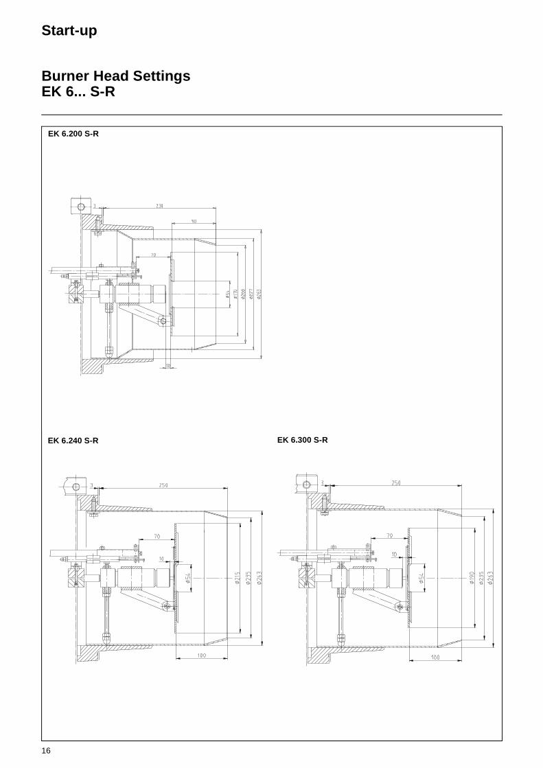
EK 6.200 S-R
Start-up
Burner Head SettingsEK 6... S-R
EK 6.240 S-R EK 6.300 S-R

17
Start-up
Burner Head SettingsEK 7... / 8... S-R
EK 7.450 S-REK 7.350 S-R
EK 8.550 S-R EK 8.700 S-R

18
Start-up
Burner Head SettingsEK 9... S-R
EK 9.850 S-R EK 9.1000 S-R

19
Installation
Mounting to BoilerElectrical ConnectionPresetting
Burner mountingFor mounting the burner to the boiler make sure the connection plate has been prepared according to the dimen-sions given in the technical datasheets.
• Install the stud bolts in the connection plate.
• Put the insulating backing and burner in place and fasten by bolts.
Check before burner installation1. Select the nozzle according to
boiler output and combustion chamber geometry.
2. Set the mixing and ignition unit according to the boiler output.For the standard factory setting refer to the burner head settings.
3. Set the ignition electrodes on the ignition burner or on the nozzle.
4. Check the burner tube installation depth according to the data speci-fied by the burner and boiler manufacturers.
Electrical connectionThe electrical connection work compri-sing all the installation materials, termi-nals and earth connections must be carried out in accordance with the appli-cable regulations. For the electrical installation of the burner care must be taken to observe the circuit diagram made out for the furnace system.The electrical connection of the burner and gas valves and instruments shall be entrusted to authorized specialists only.
NOTE: For the installation of the con-nection cables care must be taken to provide cable loops of sufficient length to allow for the swing-out of the boiler door and burner.Make sure after the completion of the electrical connection work to check the wiring of the electrical system of the burner. This should include a check of the direction of rotation of the burner motor (fan).
Boiler inspection glass coolingFor cooling and cleaning the boiler inspection glass a cooling line (e.g. hose) may be installed from the burner to the inspection glass. The burner is provided with a connection socket for this purpose.
Ignition burner ZB 12
Ign
ition
bur
ner
gas
pre
ssur
e [m
bar]
Fan pressure p [mbar]
Ignition burner ZB 2
Ign
ition
bur
ner
gas
pre
ssur
e [m
bar]
Fan pressure p [mbar]

20
Installation
Boiler lining
Boiler liningThe space between the flame tube of the burner φD and the boiler lining φ D1 must be packed with heat-resistant material, e.g. Cerafelt.
This space is not allowed to be lined with brickwork.
Burner type Dimension T φD φD1
(Standard)
EK 6.200 230 227 290
EK 6.240 250 263 290
EK 6.300 250 263 290
EK 7.350 282 306 360
EK 7.450 282 325 360
EK 8.550 362 346 400
EK 8.700 362 369 400
EK 9.850 380 386 475
EK 9.1000 380 431 475B
oile
r lin
ing

21
Installation
Oil Supply
Ring lineThe oil supply system is an important factor influencing the operational reliabi-lity of a burner system. The data nee-ded for dimensioning the pipeline system can be collected from our manual „Burner System Planning“.
Normally, a ring line is used for the oil supply to burner systems.
A ring line for heavy-oil burner systems consists of the following main compon-ents in addition to the electric heat-tra-cing lines:
oil feed pump,oil filter,gas-air separator andpressure control valves.
The electric heat-tracing and the tank heating systems will ensure that the fuel oil is kept in a pumpable condition all the time. An oil filter must be installed in the feed line upstream of each burner to prevent that dirt particles and other impurities originating from pipeline installation can damage the solenoid and pressure control valves.
To avoid burner trouble due to air bubbles, the ring line system incorpora-tes a gas-air separator at the highest point of the ring line system and as clo-sely as possible to the burner. Air bubbles will thus be prevented from entering the burner feed line but are returned to the storage tank via the return line of the ring line system.
Steam tracing or hot-water tracing systems may be used instead of the electric heat-tracing lines.
The ring line pressure must be selected in dependence of the fuel oil tempera-ture.
As can be seen from the diagram below, the static pressure of the oil must be minimum 3 bar at 130°C, for example.
Oil pressure in dependence of operating temperature
6
Lagerbehälter1BehälterheizungSchnellschlußventilElektro-BegleitheizungKugelhahn5
6
4
23
7 ÖlförderpumpeÖlförderpumpe
Ölfilter
Sicherheitsventil
Absperrventil
EntlüftungManometer
Gas-Luftabscheider1112
8910
2
14
16
16
4
3 5
13 Druckregulierventil (Einstellung entspr. Diagramm)Elektro-Ölvorwärmer14
15 Brenner
127 6
12
13
11
8
96 7 1014
15
16 Ringleitung
1 Storage tank2 Tank heating3 Quick-acting stop valve4 Electric heat tracing5 Ball valve
6 Oil filter7 Oil feed pump8 Relief valve9 Pressure gauge10 Vent valve
11 Gas-air separator12 Stop valve13 Pressure control valve
(Setting in accordance with diagram)
14 Electric oil pre-heater15 Burner16 Ring line
0
1
2
3
4
5
100 110 120 130 140 150 160Temperatur °C
Dru
ck b
ar
Temperature °C
Pre
ssur
e ba
r

22
Installation
Oil Supply
Oil hosesThe oil hoses used for heavy oil opera-tion are of high-grade steel corrugated design approved according to DIN 4798 Part 1. The hoses are jacketed with a high-grade steel mesh. They are resi-stant to temperature and chemical reac-tions of heavy fuel oil according to DIN 51603 Part 2. The mounting instructions given below should be observed.
An oil filter must be installed upstream of each burner to prevent that dirt partic-les contained in the oil and impurities from pipeline installation can enter the burner.
Technical data of oil hoses
Nominal pressure PN = 16 barTest pressure PP = 21 barOperating pressure up to 10 barOperating temperature up to 150°C
Mounting instructionsWhen mounting the oil hoses be sure they are free of distortion and relieved of stress. Take care to observe the minimum ben-ding radius „R“ (see table) and support the oil hoses on the structure.Make sure the hoses do not make con-tact with each other and avoid that they can be damaged from outside, e.g. by contact with other parts of the burner or boiler.
If burners are of swinging type make sure to mount the oil lines so that the hoses will not be subject to stress when swinging out the burner (relieving of tension).
Application
Burner type DN Lenght [mm]
Connection,both sides
Minimum bending radius R [mm]
EK 6.170/200 12 1300 R 1/2" 110
EK 6.240/300 20 1300 M 30x1,5 240
EK 7 20 1300 M 30x1,5 240
EK 8/9 25 1300 M 38x1,5 250

23
Viscosity as a Function of Oil Temperature
Temperature [°F]
Kin
emat
ic v
isco
sity
ν [
mm
²/s
= cS
t] Max. feeding viscosity
Maximum viscosity of heavy fuel oil acc. to DIN 51 603
Failure of heavy fuel oil
Temperature [°C]
max. Atomizing viscosity heavy fuel oil
Maximum viscosity of fuel oil grade EL
acc to DIN 51603
usual feeding viscosity: 60 - 100 cStusual atomizing viscosity: 10 cSt
24
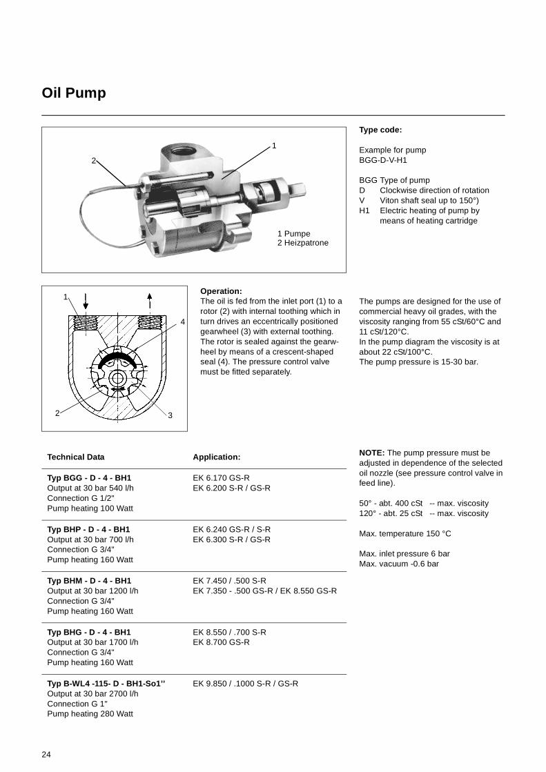
Oil Pump
Operation:The oil is fed from the inlet port (1) to a rotor (2) with internal toothing which in turn drives an eccentrically positioned gearwheel (3) with external toothing. The rotor is sealed against the gearw-heel by means of a crescent-shaped seal (4). The pressure control valve must be fitted separately.
Type code:
Example for pumpBGG-D-V-H1
BGG Type of pumpD Clockwise direction of rotationV Viton shaft seal up to 150°)H1 Electric heating of pump by
means of heating cartridge
The pumps are designed for the use of commercial heavy oil grades, with the viscosity ranging from 55 cSt/60°C and 11 cSt/120°C.In the pump diagram the viscosity is at about 22 cSt/100°C.The pump pressure is 15-30 bar.
NOTE: The pump pressure must be adjusted in dependence of the selected oil nozzle (see pressure control valve in feed line).
50° - abt. 400 cSt -- max. viscosity120° - abt. 25 cSt -- max. viscosity
Max. temperature 150 °C
Max. inlet pressure 6 barMax. vacuum -0.6 bar
1 Pumpe2 Heizpatrone
1
2
1
2 3
4
Technical Data Application:
Typ BGG - D - 4 - BH1Output at 30 bar 540 l/hConnection G 1/2"Pump heating 100 Watt
EK 6.170 GS-REK 6.200 S-R / GS-R
Typ BHP - D - 4 - BH1Output at 30 bar 700 l/hConnection G 3/4"Pump heating 160 Watt
EK 6.240 GS-R / S-REK 6.300 S-R / GS-R
Typ BHM - D - 4 - BH1Output at 30 bar 1200 l/hConnection G 3/4"Pump heating 160 Watt
EK 7.450 / .500 S-R EK 7.350 - .500 GS-R / EK 8.550 GS-R
Typ BHG - D - 4 - BH1Output at 30 bar 1700 l/hConnection G 3/4"Pump heating 160 Watt
EK 8.550 / .700 S-R EK 8.700 GS-R
Typ B-WL4 -115- D - BH1-So1’’Output at 30 bar 2700 l/hConnection G 1"Pump heating 280 Watt
EK 9.850 / .1000 S-R / GS-R

25
Oil Pump
Filling the oil pump with oilTo avoid seizing of the gearwheel system of the pump the user should fill the pump and the oil supply system with fuel oil or motor oil prior to the initial operation of the burner plant.
Mounting the instrumentsBefore the adjustment of the burner it will be required to mount pressure gau-ges for sensing the feed pressure and pump pressure. Alternatively, the pres-sure gauges installed in the oil pump feed line and pressure control valve return line can be used for this purpose.
NOTE: The pressure gauges must be removed and the connections sealed by suitable means after the burner system has been taken into opera-tion.
If the pressure gauges are not remo-ved from the burner these must be shut off with stop valves.
BleedingOpen the feed and return stop valves and make sure the ring line is in opera-tion, if provided.
Reduce the oil pressure on the pressure control valve as described in the related manual.
Bleed the hydraulic oil system of the burner with the ring line pressure.
Turn on the pump by pressing the swit-ching contactor. Check for correct direc-tion of rotation, for proper oil delivery and for absence of leaks. Bleed the pump via the pressure gauge connec-tion, for example.
12

26
Pump Output Diagram
Viscosity approx. 22 cSt
Pu
mp
ou
tpu
t [l
/h]
Pump pressure [bar]

27
Electric oil pre-heater
Pumpfeed
To the nozzle
Electric oil pre-heater
Type NE 622 12 kWType NE 1032 20 kWOperating pressure max. 40 barRegulating thermostat 60-160 °C
Two electric heating elements rated 6 kW and 10 kW each are installed in the pre-heater.
Functional descriptionThe pumpable fuel oil enters the pre-heater at the top, flows through the 2 heating elements from outside to inside or from front to rear and is heated up to the final temperature set at the regula-ting thermostat.
A temperature limiter set to maximum temperature is fitted as a safety feature.
1 Pre-heater housing2 Heating element seal3 Heating element
2 x 6 kW / 2 x 10 kW4 Thermostat controller5 Safety thermostat6 Mounting element (thermostats)7 Thermostat housing8 Thermostat housing seal
Electric oil pre-heater

28
Thermostat Setting
Thermostat setting
Figure 1 shows the factory setting in °C for the thermostats used with burner types EK 6/EK 7 GS-R / E with one pre-heater.
Figure 2 shows the factory setting in °C for the thermostats used with burner types EK 8/EK 9 GS-R / E with two pre-heaters.
The temperature should be adjusted in accordance with the oil grade used. The viscosity on the oil nozzle should be approx. 15-20 cSt; see Viscosity Dia-gram.
Figure 1Pre-heater 1
Regulatingthermostat
Safety thermostat
Enablethermostat
Regulatingthermostat
Enablethermostat
Figure 2
Pre-heater 1 Pre-heater 2
Regulatingthermostat
Safety thermostat
Enablethermostat
Regulatingthermostat
Regulatingthermostat
Safety thermostat
Enablethermostat
Regulatingthermostat

29
Return Nozzle Rod MAT
Functional descriptionThe oil delivered by the burner pump will enter the feed pipe (9) via the connection block (10). Then it flows through the feed pipe (9) at the pre-set pressure directly to the return nozzle. Part of the oil delivered will be returned through the return flow pipe (6) via the return flow hole of the nozzle.
The return flow rate is controlled according to the required output using an output pressure control valve.Approved shut-off valves are installed directly upstream of the inlet to the nozzle rod in the oil feed and oil return lines.
1. Union nut2. Nozzle plate3. Intermediate plate
(is only used for special combination of nozzles)
4. Swirl chamber 5. Nozzle rod6. Return pipe7. Feed flow8. Return flow9. Feed pipe10. Connection block
Heat tracing line for nozzle rodThe heat tracing line (Item 161) is mounted on the nozzle rod in a way that the feed pipe and return pipe are con-stantly heated.
Heat tracing Ratingsystem
EK 60 100 WEK 7 - 9 150 W

30
Nozzle Output Curves
EK 6... S-R / GS-R/EEK 7... S-R / GS-R/E
Nozzle output curves EK 6... S-R / GS-R/E
Oil viscosity 20 cSt
Ret
urn
pre
ssu
re [
bar
]
Oil throughput rate [ kg/h ]
Nozzle plate 120-13391-6Swirl chamber 60-2,5-12121-2Pump pressure 29 bar
Nozzle plate 110-13391-7Swirl chamber 60-2,5-12121-2Pump pressure 26 bar
Nozzle plate 130-13391-5Swirl chamber 70-3-937-110Pump pressure 26 bar
Nozzle output curves EK 7... S-R / GS-R/E
Oil viscosity 20 cSt
Ret
urn
pre
ssu
re [
bar
]
Oil throughput rate [ kg/h ]
Nozzle plate 160-13391-2Swirl chamber 80-3-937-112Pump pressure 27 bar
Nozzle plate 180-13391-1Swirl chamber 90-3-937-114Pump pressure 29 bar
Nozzle plate 220-12125-22Swirl chamber 120-4-937-118Pump pressure 25 bar

31
Nozzle Output Curves
EK 8 / 9... S-R / GS-R/E
Nozzle output curves EK 8... S-R / GS-R/E
Oil viscosity 20 cSt, pump pressure 28,5 bar
Ret
urn
pre
ssu
re [
bar
]
Oil throughput rate [ kg/h ]
Nozzle plate 220-12125-22Swirl chamber 120-4-937-118
Nozzle plate 240-12125-24Swirl chamber 120-5-12121-18
Nozzle output curves EK 9... S-R / GS-R/E
Ret
urn
pre
ssu
re [
bar
]
Oil throughput rate [ kg/h ]
Nozzle plate 260-12125-26Swirl chamber 120-4-937-118
Nozzle plate 300-16231-19Swirl chamber 130-5,5-937-119
Nozzle plate 325-16231-19Swirl chamber 140-6-937-4
Oil viscosity 20 cSt, pump pressure 28 bar

32
Burner Operation
Oil Burner OperationHydraulic Diagram
Functioning of the steplessly adjustable heavy oil burnerThe pumpable heavy oil is fed to the burner pump by an oil feed pump (Item 176) via the ring line, the gas-air sepa-rator and the daily service tank. The burner pump will flush the heavy oil heated up in the pre-heater (Item 400) via the flushing valve (Item 181) and the pressure control valve (Item 187) to ensure a viscosity suitable for combu-stion. After the preset oil temperature has been reached the flushing valve (Item 181) will be closed. The oil pres-sure control valve (Item 187) installed downstream of the burner pump will keep the atomizing pressure at a con-stant level (approx. 25-30 bar) accor-ding to the overflow principle. The pump pressure should be set 2-3 bar higher to compensate for pressure losses in the nozzle rod (Item 180), the pre-heater and the solenoid valves (Item 178). The nozzle rod has a feed and a return connection. The return pipe incorporates 2 solenoid valves (Item 183) and an output pressure con-trol valve.
After the solenoid valves (Item 178) in the feed line to the nozzle rod has ope-ned, the minimum output of the burner is selected by setting the minimum return pressure (3-9 bar) on the output pressure control valve (Item 184) accor-dingly.When setting the compound controller to maximum output, the return pressure setting (approx. 13-20 bar) will be increased according to nozzle size. This return pressure will now dictate the maximum output of the return nozzle in accordance with the nozzle output cur-ves and the nominal output of the heat generator. Simultaneously with the oil flow rate control, an air flow rate control-ler incorporated in the compound con-troller will adjust the air flow rate required for the combustion of the sel-ected oil quantity.When using the nozzle rod type DG 75 with shut-off valves in the feed and return lines, the system can be configu-red without a solenoid valve (Item 178) and a solenoid valve (Item 183) each.
120 Air damper175 Filter176 Pump177 Pressure gauge with stop valve178 Feed solenoid valve (115 V)180 Nozzle rod MAT181 Flushing valve183 Return solenoid valve (115 V)184 Output control valve187 Pressure regulating valve189 Electric heating tracer311 Return oil pressure switch 312 Feed oil pressure switch 349 Actuator, mechanical compound400 Pre-heater (Option, pre-heater
can be installed external)
Always 1x 178 und 1x183 electrical connected in-line
175
174
176
177
180
189
178
178
184120
181
349
187
400 312
311
177
183 183
Hydraulic diagram

33
Start-up
Checking Procedure
Check the following prior to the initial operation of the boiler system:
• Take care to observe the operating instructions supplied by the boiler manufacturer. The boiler must be mounted ready for operation.
• Ensure that the heating system is filled with water to capacity.
• Check the complete system for correct electrical wiring.
• Check the burner motor for correct direction of rotation.
• Check for the proper setting of the temperature and pressure controllers, limiters, safety switches and electrical limit switches.
• Bleed the fuel-carrying lines (make sure they are free of air).
• Check tank, lines and oil pump are fil-led with oil and correct oil nozzle is fit-ted.
• Check the oil hydraulic system is free of leaks.
• Check the exhaust gas ports are ope-ned and adequate fresh air intake is ensured.
• With burner in starting position check that air damper is in „CLOSED“ posi-tion.
• Check that automatic furnace control-ler is unlocked and in its original posi-tion.
Checks before start-up
Check direction of rotation of the burner motor and/or burner pump.
Checking of the direction of rotation of the burner motor (direct on-line starting) is carried out by pressing the contactor.
With Star-Delta connection the mains and the star contactor must be operated simultaneously.
The direction of rotation of the burner motor is correct if the ventilator impeller turns in the direction of the mixing unit.
The correct direction of the oil pump can be determined by the stamped directio-nal arrow.
Oil start-upOpen all shut-off valves of oil supply system.• Fill pump with oil.• Set fuel selector switch to its „Oil“ posi-
tion.• Mount pressure gauge in the feed line
and return line.• Mount the pressure gauge for
checking the pump suction pressure.
BleedingShortly start the burner and check for proper direction of rotation. Bleed the oil line and oil pump.
CAUTION: The hydraulic system has been filled with test oil by the manufac-turer. This may cause ignition trouble when initially operating the system. To protect the pump, the oil pressure con-troller is factory-set at zero pressure. When starting the burner take care to increase the oil pressure slowly to the operating level.
Ensure a functional check of the bur-ner program procedure is carried out before the first fuel flow release.
• Disconnect the oil solenoid valve in the feed line (see electrical circuit dia-gram).
• Start the burner and check that the program process follows the described sequence for starting up:
1. Blower 2. Air valve, pre-aeration
Check limit switch setting 3. Air pressure control 4. Air valve to partial output
Check limit switch setting 5. Ignition 6. Open valves 7. Shut-down on fault at the end of
the safety period (see automatic furnace controller)
• Unlock the automatic furnace control-ler.

34
Start-up
Pressure Control Valve in Feed Line
Pressure control valve
The pressure control valve has been provided for setting the pump pressure in the feed line.
A piston (1) movably arranged in a cylinder is pressed against the valve cone (3) by a spring (2). As the pres-sure on the side of the valve cone rises above the spring pressure, the piston will be lifted and the oil caused to flow over to the pressureless side.
For the installation of overflow valves of this type the following general informa-tion should be observed:
The spring side (spring can be seen from outside) must in any case be cho-sen to be the return side, i.e. the pres-sureless side. Consequently, the direction of overflow is from the pressu-rized side to the pressureless spring side.
Any counterpressure on the return side must thus be added to the selected spring pressure setting.
It is of no consequence for the operation of this type of valves whether they are mounted in continuous lines or at line ends.
Pressure settingProceed with screwing out the screw cap (5) to allow the desired pump pres-sure to be selected with setscrew (4). Turn the screw clockwise or counter-clockwise to increase or reduce the pressure, respectively.
Flushing process (see hydraulic diagram):During the flushing process the solenoid valve (178) will be in its closed position while the solenoid valve (181) will be open. This causes the heavy fuel oil to flow via the pressure control valve (187) into the return pipe so that a closed-cir-cuit flushing process will be ensured.
Items: to nozzle rod
1 Piston2 Spring3 Valve cone4 Regulating screw5 Screw cap
Return
Pumpfeed
35
Start-upMechanical Compound Control
Output Pressure Control Valve in Return Line
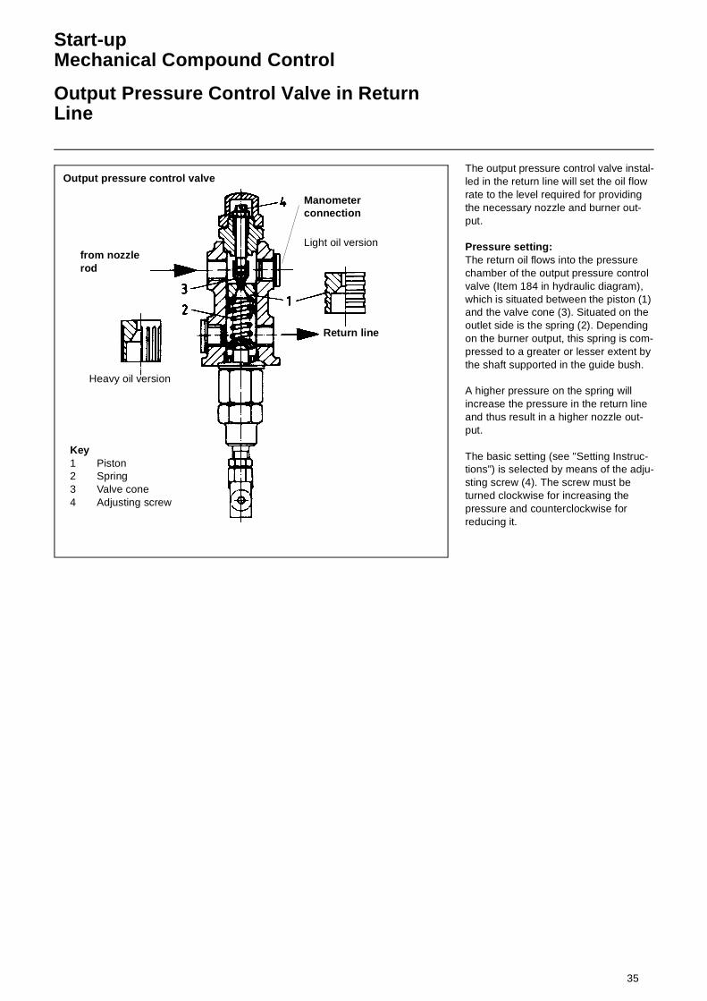
The output pressure control valve instal-led in the return line will set the oil flow rate to the level required for providing the necessary nozzle and burner out-put.
Pressure setting:The return oil flows into the pressure chamber of the output pressure control valve (Item 184 in hydraulic diagram), which is situated between the piston (1) and the valve cone (3). Situated on the outlet side is the spring (2). Depending on the burner output, this spring is com-pressed to a greater or lesser extent by the shaft supported in the guide bush.
A higher pressure on the spring will increase the pressure in the return line and thus result in a higher nozzle out-put.
The basic setting (see "Setting Instruc-tions") is selected by means of the adju-sting screw (4). The screw must be turned clockwise for increasing the pressure and counterclockwise for reducing it.
Output pressure control valve
Key1 Piston2 Spring3 Valve cone4 Adjusting screw
Light oil version
Heavy oil version
from nozzle rod
Manometerconnection
Return line

36
Start-upMechanical Compound Control
Oil/Air Flow Rate Adjustment
Oil flow rate adjustment 1. Proceed with removing the protec-
tive hoods from the SQM actuator and compound controller. Start the burner. Turn off the control system to ensure the compound controller remains in its minimum output position. After the ignition proceed as follows:Check the furnace and readjust the air flow rate according to the air flow rate adjusting instructions.Turn clockwise to increase the air flow rate.Turn counterclockwise to reduce the air flow rate.Loosen the two locking screws (1) of the eccentric disk (3) so that this can be rotated eccentrically relative to the carrier disk (2). Loo-sen the counter nut (4), adjust the support (5) until the ball bearing (6) of the pressure regulator valve makes contact with the eccentric disk (3). Make sure during the adjustment of the pressure regula-tor valve and thereafter to observe the combustion process. Care should be taken that the burner is not operated with insufficient air flow rate.
NOTE: Adjust the air pressure switch after the burner has been started (see section entitled „Air Pressure Switch“). If the air pressure switch is set at too high a pressure level this may lead to burner shut-off. Reduce the pressure setting of the air pressure switch if required. 2. Measuring the low-load oil
throughput ratea) either with oil counter orb) by way of return pressure and nozzle diagrams
3. Adjusting the low-load oil throughput rateFor this purpose, turn the support (5). If the pressure is too high, turn the support into the shaft to reduce the length of shaft and support. Proceed in reverse order if the pressure is found to be low. While doing this, observe the combustion process and readjust the air flow rate as required.
4. Increasing to maximum load in stepsIncrease the burner output to maximum load in small steps while observing the combustion process at the same time. Read-just the air damper if required.
5. Adjusting the „Oil max.“ limit switch at about 120°.Turn the compound controller until the slide block (8) is in a position approximately opposite to the second last setting screw. Check that the „Oil max.“ limit switch operates in this position.
6. Measuring the full-load oil throughput ratea) either with oil counter orb) by way of return pressure and nozzle diagrams
7. Adjusting the full-load oil throughput rateIf the return pressure is found to be too low it will be required to increase the amount of lift by means of setting screw (7).Turn clockwise to increase the oil flow rate.Turn counterclockwise to reduce the oil flow rate.While doing this, observe the combustion process and readjust the air flow rate if required.
8. Each time the cam disk has been changed make sure to readjust the minimum pressure of the out-put pressure regulator valve in the low-load position. After this adju-sting work, turn the compound controller into its maximum posi-tion again, read the return pres-sure, and return it to its minimum position. Repeat this operation until the correct minimum and maximum pressure settings have been achieved. Alternatively, the rocker arm (10) of the actuator may be changed over to discon-nect the drive from the control ele-ment so that the compound controller plate can be moved by hand.
NOTE: The compound controller does not have a mechanical stop member. It must not be turned beyond the limits of the setting screw ranges.
Air flow rate adjustmentThe cam plate of the compound control-ler is factory-set so that the air dampers are fully opened in maximum load posi-tion and closed in minimum load posi-tion. For the fine adjustment of the air flow rate according to the oil throughput rate, proceed with the minimum oil throughput rate and increase the com-pound controller setting step by step while at the same time selecting the air flow rate by means of the setting screws as required for the hygienically sound combustion of the oil. Turning clockwise will increase the air flow rate. Turning counterclockwise will reduce the air flow rate.After the last step when the maximum oil pressure has been reached, proceed by reducing the compound controller setting step by step again and check the flame and the combustion data at the same time.
10
5 4 1
62 3
7
8 12

37
Adjusting Instructions Mechanical Compound
Electrical ActuatorLimit Switch Setting
Technical data SQM actuator
Voltage 230 V -15%50 / 60 Hz240 V +10% 50 / 60 Hz
Power input 9 VAMax. contact load 250 V 10 (3) AMounting position as requiredAmbienttemperature -20°C + 60°CProtectionclassification IP 54, DIN 40050Weight 1,7 kg
Positions1 Cam plate2 Scales for switching point setting3 Terminals4 Actuator position indicator5 Rocker arm for uncoupling6 Return potentiometer7 Connection for „N“
DescriptionThe SQM actuator is intended for use with two-stage sliding or modulating oil, gas or dual-fuel burners. The reversible actuator is fitted with a synchronous motor which drives a shaft via a gear-box. The shaft end carries a coupling to drive the fuel and combustion air con-trolling element.
The SQM actuator has been designed for dual-wire control by controller or switching units with change-over con-tacts. Potentiometers can be installed for a range of applications on custo-mer's request.The 60 Hz frequency will reduce the running times by approx. 17 %.
Limit switch factory setting
The limit and auxiliary switches are set by means of manually adjustable latching cam plates. Scales are fitted between the disks to facilitate the selec-tion of the switching points. The cam plates are provided with a small pointer for indicating the switching point of a scale between the setting ran-ges. An additional scale fitted to the end of the cam roller serves to indicate the position of the actuator.
The drive unit may be disconnected from the controlling element by chan-ging over a rocker arm mounted to the gearbox. This will allow any desired position of the controller plate to be sel-ected by hand. Drive and output will be coupled in the vertical position of the rocker arm.
The fuel-air curve should be set over the full range of the cam plate so that operating safety will be retained also when the limit switch is overrun.
SQM10/11 SQM20/21
Running time at 130° turning angle
42 Sek. 66 Sek.
Torque 10 Nm 20 Nm
Descrip-tion
Pre-setting Function
II 0°Air dampers closed
III 30° Oil min.
I 130° Oil max.
IV 20° Gas min.
V 130° Gas max.

38
Start-up
Flushing and Oil Feed Start Thermostat ATH 22
OperationThe surface-type dual-thermostat works according to the principle of volumetric expansion. If the temperature of the fluid in the sensor system consisting of sensor, capillary line and membrane changes this will also cause the volume to change. The resultant lifting move-ment of the membrane will actuate the quick-break switch via a lever.
Switching function TR/TW/STW(STB)If the temperature available at the tem-perature sensor exceeds the limit set-ting this will cause the switching ram of the microswitch to be relieved of load via the sensor system and the electric circuit opened or closed. In case the temperature falls below the limit setting (by the switching difference) the micro-switch will be returned to its initial posi-tion.
Temperature sensor with and without protective sleeveThe temperature will be sensed by means of the temperature sensor. Make sure the temperature sensor is immer-sed in the fluid over its full length because otherwise the switching point may be subject to larger variations.
1 Remote line 2 Temperature sensor3 Protective sleeve 4 Pressure spring
For code „f“ and connection mode „Ü“ the temperature sensor will be locked by fitting a clamp to the capillary line and securing the same by a screw in the extended sleeve opening. For codes „f“ and connection modes B, C, D, E, ES, Q and V the sensor is locked by the manufacturer by means of the terminal attached to the capillary line.
Electrical connection1. Opening the housingRemove the two sealable fillister-head screws (1) at the housing top (2) and remove the latter.
1 Sealable screws 2 Housing top3 Housing bottom 4 Housing journal
2. ConnectionFeed the line through the self-sealing grommet Pg 11 and connect as shown on the connection diagram. The con-nection diagrams relating to the thermo-stats are fixed to the inside of their housing tops.
5 Terminal screw6 Restart button (must move freely)7 For type attachments s, g and b8 For type attachment r9 Self-sealing grommet Pg 11
Connection diagramCodes 11, 12, 22, 120, 220, 2020 System I and II with change-over con-tact.
Technical dataSetpoint adjustment:For code 1:Adjust switching point from outside by turning the setpoint screw accordin-gly.
For codes 2, 20, 7, 70:Remove the top of the housing and adjust the switching point by turning the setpoint screw with a screw driver watching the interior scale.
Adjusting range: 20-150°C
Maximum switching current:AC 250 V, 10(2) A, cosϕ=1(0.6)DC 250 V, 0.25 A
Switching difference in measuring system filled with liquidTR, TW 3+1% standard feature
6+2% on request 1.5 ± 0.5% against extra price
Permissible ambient temperature on switching head and remote linein use filled with liquid or gas max. +80°C
Operating fluidwater, oil, air, superheated steam
Protection classificationEN 60 529-IP54

39
Adjusting Instructions
Oil Pressure Switch (Option)Air Pressure Switch
Oil pressure switch Oil pressure switches are provided to burners for monitoring the oil pressure. Depending on the burner design, the oil pressure switches can be installed eit-her in the return line only or in both the return line and feed line. The cut-out pressure will be selected depending on the burner system data (ring line pres-sure, oil nozzle, etc.).
Oil pressure damperAn oil pressure damper or a capillary pipe may be installed in the connection fitting (2) to make up for oil pressure variations.
Operating pressure adjustmentFor adjusting the operating pressure, remove the setting know (1) by pulling it upward and reinstall it again the other way round. After the adjustment has been completed make sure to install the setting know in its original position again.
Switching differenceThe switching difference may be selec-ted on the pressure switches within the limits shown in the table. For the adjust-ment, turn the threaded pin in the set screw (3) for the switching point. One turn will change the switching difference by approx. 20 % of the total range of the switching difference. The oil pressure switch has a facility for attaching a seal.
1
2
3
Type Setting range
Switching difference Location
DSB 143 F... 0 - 6 bar 0,3 - 1,6 bar Return line acc. to DIN / EN
DSB(F) 170 F... 15 - 40 bar 1,2 - 4,5 bar Feed line acc. to DIN/EN in pumps without quick-action stop valve
DSF 146 F... 0 - 10 bar 0,5 - 2,5 bar Return line acc. to TRD 604/ 72h
DSB 158 F... 3 - 25 bar 1,0 - 4,3 bar Feed line acc. to TRD 604/ 72h
Air pressure switchThe air pressure switch is provided for monitoring the pressure of the combu-stion air fan. The pressure switch DL 50A has been designed for switching on, off or over an electric circuit in the case of changes of the actual pressure levels from the set-point setting. The pressure switch DL 50A can be used as overpressure, vacuum or differential pressure monitor for air and non-aggressive gases but not for gases according to DVGW Worksheet G 260/l.
Determining the differential pre-flushing pressure and adjusting the differential pressure switch• Burner in the pre-aeration phase.• Measure pressure on test
connection (2).• Measure vacuum on test
connection (3).• Add the measured pressures.• Set the scale to 90% of the calculated
value.
CertificationThe pressure switch has been tested in accordance with DIN 3398 Part 2 and is registered by CE/DIN-DVGW. It has been registered in other important gas consumption countries.
Switch function testTest buttons are provided to check the switch functions for proper operation (with safety cut-out and interlock). The burner is normally run in partial-load condition when testing the safety functions. On pressing button (4) the vacuum will be removed which causes the differential pressure to drop below the required level. If it is necessary to test the pressure switch functions under full-load conditions this may be done by pressing button (1).

40
Operation
Automatic Furnace Controller LFL 1... / LGK 16...Regulator KS 92
The automatic furnace controllers LFL... and LGK 16... are designed to control and monitor burners of step-ping or modulating mode of operation. For a detailed functional description of the automatic furnace controllers with technical data and design informa-tion see the enclosure hereto and further descriptive material:
LFL 1...-7451 DLGK 16...-7785 D
Functional diagramLFL 1... / LGK 16...
A = Starting type intervalA-B= Flame development intervalB = Burner has reached operating
positionB-C= Burner operation
(heat generation)C-D= regular shut-offt1 Pre-ventilating timet2 Safety timet3 Pre-ignition timet4 Fuel valve enablet5 Load regulator enablet11 „OPEN“ run time of air dampert12 „CLOSE“ run time of air damper
R = Temperature or pressurecontroller
G = Fan motorZ = Ignition transformerBV= Fuel valve(s)
LR= Load regulatorLK= Air damperRV= Steadily adjustable fuel valveFS= Signal of flameZBV= Ignition burner valve
In steplessly variable burners use is made of the KS 92 industrial controller. This has specifically been designed for use with furnace systems, preferably for temperature and pressure controllers in conjunction with burners featuring steplessly variable fuel throughput rates. For adjusting the controller to the controlled condition, the desired set-point range and the way of detecting the actual value, the software configuration is structured accordingly.
Technical documentationKS 92 PMA
41
Adjusting Instructions
Flame MonitorSensor Current Measurement
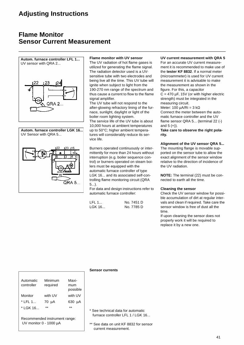
Flame monitor with UV sensorThe UV radiation of hot flame gases is utilized for generating the flame signal.The radiation detector used is a UV-sensitive tube with two electrodes and being live all the time. This UV tube will ignite when subject to light from the 190-270 nm range of the spectrum and thus cause a current to flow to the flame signal amplifier.The UV tube will not respond to the after-glowing refractory lining of the fur-nace, sunlight, daylight or light of the boiler room lighting system.The service life of the UV tube is about 10,000 hours at ambient temperatures up to 50°C; higher ambient tempera-tures will considerably reduce its ser-vice life.
Burners operated continuously or inter-mittently for more than 24 hours without interruption (e.g. boiler sequence con-trol) or burners operated on steam boi-lers must be equipped with the automatic furnace controller of type LGK 16... and its associated self-con-trolling flame monitoring circuit (QRA 5...).For data and design instructions refer to automatic furnace controller:
LFL 1... No. 7451 DLGK 16... No. 7785 D
Sensor currents
* See technical data for automatic furnace controller LFL 1 / LGK 16...
** See data on unit KF 8832 for sensor current measurement.
UV current measurement with QRA 5For an accurate UV current measure-ment it is recommended to make use of the tester KF 8832. If a normal meter (microammeter) is used for UV current measurement it is advisable to make the measurement as shown in the figure. For this, a capacitorC = 470 µF, 15V (or with higher electric strength) must be integrated in the measuring circuit. Meter: 100 µA/Ri = 3 kΩConnect the meter between the auto-matic furnace controller and the UV flame sensor QRA 5... (terminal 22 (-) and 5 (+)).Take care to observe the right pola-rity.
Alignment of the UV sensor QRA 5...The mounting flange is movable sup-ported on the sensor tube to allow the exact alignment of the sensor window relative to the direction of incidence of the UV radiation.
NOTE: The terminal (22) must be con-nected to earth all the time.
Cleaning the sensorCheck the UV sensor window for possi-ble accumulation of dirt at regular inter-vals and clean if required. Take care the sensor window is free of dust all the time. If upon cleaning the sensor does not properly work it will be required to replace it by a new one.
Automatic controller
Minimum required
Maxi-mum possible
Monitor with UV with UV
* LFL 1... 70 µA 630 µA
* LGK 16... ** **
Recommended instrument range: UV monitor 0 - 1000 µA
Autom. furnace controller LFL 1...UV sensor with QRA 2...
Autom. furnace controller LGK 16...UV Sensor with QRA 5...
42
Servicing Instructions
Burner MaintenanceFan Impeller
Furnaces should be inspected once a year. An extract from DIN 4755 reads as follows:
„To ensure a high operational readi-ness, functionality, safety and econo-mic efficiency, the user should have the boiler system inspected by an authorized person of the manufactu-rer or other specialist once a year. The whole system must be checked for proper operation and faults detected should be rectified without delay. It is advisable however to make another inspection of the system in addition to the one speci-fied herein.“ The inspection should comprise the following work:
1. Inspect the boiler internals and insulating packages and replace by new ones if required. Check boiler for possible accumulation of dirt.
2. Remove the nozzle, check it and replace it by new one if required.
3. Clean the ignition electrodes.4. Check the ignition electrode and
spark functions and readjust if required.
5. Clean the burner interior and exte-rior.
6. Clean the fan impeller.7. Check the fan impeller for possi-
ble deformation and cracks.8. Clean the flame sensor.9. Clean the filters and screens.10. Check the electrical connections.11. Check the flame tube and retarder
disk/swirl element (replace if required) and check the burner head setting after such replace-ment
12. Check the control equipment for proper operation, setting and safety period.
13. Check the pressure switch for pro-per setting and operation.
14. Check the oil pump by measuring its pressure and vacuum levels.
15. Check the hydraulic oil system for absence of leaks.
16. Check the oil hoses for possible damage and twisting.
17. Clean the air damper and check for smooth operation.
18. Check the combustion process and make exhaust gas tests:• Fuel throughput rate adjustment
• Heating chamber temperature (intake temperature)
• Exhaust gas temperature• Pressure in combustion
chamber and exhaust gas pipe• CO2 and O2 contents of exhaust
gases• CO test, soot test• UV sensor current measurement
19. Enter measured data in test record.
Important instructions: With serious contamination or when cle-aning cloths or other items are sucked in, there is a danger that imbalances will occur which, in extreme cases, could lead to Deformation of and crack forma-tion on the impeller. The same can hap-pen with defective ball bearings on the blower motor, which can cause an imbalance of the motor shaft and trans-fer of this imbalance to the impeller. Should Deformation or cracks occur, the impeller must be exchanged without delay.
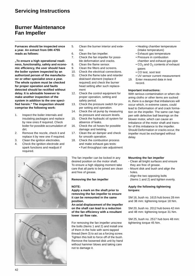
The fan impeller can be locked in any desired position on the motor shaft. To ensure a high slipping moment take care that all parts to be joined are clean and free of grease.
Removing the fan impeller
NOTE: Apply a mark on the shaft prior to removing the fan impeller to ensure it can be remounted in the same position.An axial displacement of the impeller on the shaft can lead to a reduction of the fan efficiency with a resultant lower air flow rate.
For removing the fan impeller unscrew the bolts (Items 1 and 2) and install one of them in the hole with semi-tapped thread (Item 3) to act as a forcing screw. Tighten this bolt to force off of the bush. Remove the loosened disk unit by hand without hammer blows and taking care not to damage it.
Mounting the fan impeller- Clean all bright surfaces and ensure
they are free of grease.- Mount disk and bush and align the
holes.- Align the two opposing bolts
(Items 1 and 2) and tighten evenly.
Apply the following tightening torques:
SM 16, bush no. 1615 hub bores 28 mm and 38 mm: tightening torque 18 Nm.
SM 20, bush no. 2012 hub bores 42 mm and 48 mm: tightening torque 31 Nm.
SM 25, bush no. 2517 hub bore 48 mm: tightening torque 45 Nm.

43
Exhaust Gas Test
Exhaust gas testTo ensure an economically efficient and trouble-free operation of the system it will be necessary to adjust the burner specifically in accordance with the furnace system. This is achieved by means of a fuel-combustion air compound control unit which adjusts the burner to ensure a proper combustion. Exhaust gas tests are required for this purpose. The percentage CO2 and O2 and the exhaust gas temperature will have to be measured to determine the efficiency and combustion quality.Prior to any measurement make sure to check the boiler and exhaust gas system for absence of leaks.
Secondary air will falsify the measured resultsCheck that the exhaust gases have a residual oxy-gen (O2) content as low as possible and a carbon dioxide (CO2) content as high as possible.The carbon monoxide content of the exhaust gases must be below the currently applicable specificati-ons in all load stages.In the fuel oil combustion mode the permissible soot number in the exhaust gas is not allowed to be exceeded.
Ratio between O2- and CO2- for light oil EL (CO2max =15,40%)
% O2 % CO2 % O2 % CO2
0,00 15,40 3,00 13,190,10 15,33 3,10 13,120,20 15,25 3,20 13,040,30 15,18 3,30 12,970,40 15,11 3,40 12,890,50 15,03 3,50 12,820,60 14,96 3,60 12,750,70 14,88 3,70 12,670,80 14,81 3,80 12,600,90 14,74 3,90 12,531,00 14,66 4,00 12,451,10 14,59 4,10 12,381,20 14,52 4,20 12,311,30 14,44 4,30 12,231,40 14,37 4,40 12,161,50 14,29 4,50 12,081,60 14,22 4,60 12,011,70 14,15 4,70 11,941,80 14,07 4,80 11,861,90 14,00 4,90 11,792,00 13,93 5,00 11,722,10 13,85 5,10 11,642,20 13,78 5,20 11,572,30 13,71 5,30 11,492,40 13,63 5,40 11,422,50 13,56 5,50 11,352,60 13,48 5,60 11,272,70 13,41 5,70 11,202,80 13,34 5,80 11,132,90 13,26 5,90 11,05
O2 21CO2max CO2gem–
CO2max-----------------------------------------------× %==O2 21CO2max CO2gem–
CO2max-----------------------------------------------× %==
Ratio between O2- and CO2- forheavy oil (CO2max =15,90%)
% O2 % CO2 % O2 % CO2
0,00 15,90 3,00 13,630,10 15,82 3,10 13,550,20 15,75 3,20 13,480,30 15,67 3,30 13,400,40 15,60 3,40 13,330,50 15,52 3,50 13,250,60 15,45 3,60 13,170,70 15,37 3,70 13,100,80 15,29 3,80 13,020,90 15,22 3,90 12,951,00 15,14 4,00 12,871,10 15,07 4,10 12,801,20 14,99 4,20 12,721,30 14,92 4,30 12,641,40 14,84 4,40 12,571,50 14,76 4,50 12,491,60 14,69 4,60 12,421,70 14,61 4,70 12,341,80 14,54 4,80 12,271,90 14,46 4,90 12,192,00 14,39 5,00 12,112,10 14,31 5,10 12,042,20 14,23 5,20 11,962,30 14,16 5,30 11,862,40 14,08 5,40 11,812,50 14,01 5,50 11,742,60 13,93 5,60 11,662,70 13,86 5,70 11,582,80 13,78 5,80 11,512,90 13,70 5,90 11,43
O2 21 2max CO2gem–
CO2max-----------------------------------------× %==

44
Exhaust Gas Test
Trouble Shooting Instructions
Exhaust gas lossExhaust gas loss by way of free heat will occur as a result of the temperature difference between the fuel-air mixture entering the furnace chamber and the gases discharged. Any increase in the excess of air and the resultant higher exhaust gas volume will cause the exhaust gas loss to rise. The exhaust gas loss can be calculated as follows:
Example:Data measured in fuel oil mode:CO2 content of exhaust gases 12,8%Exhaust gas temperature 195°CAir intake temperature 22°C
The exhaust gas loss can be calculated as follows:
q A = exhaust gas loss in %t A = exhaust gas temperature
in °Ct L = combustion air temperature
in °CCO2= volumetric content of carbon
dioxide in %
qA tA tL–( )A1
CO2----------- B+
⋅=
Light oilEL
Heavy oilS
A1 = 0,50 0,490
B = 0,007 0,007
In any case of trouble proceed with checking the basic conditions for a proper operation of the boiler system:1.Is electric power available?2.Is fuel oil contained in the tank?3.Are the shut-off valves opened?4.Are all control and safety instruments
such as boiler thermostat, water supply failure cut-out, limit switches,
etc. properly set?
1. Ignition failure
Cause Remedy
Ignition elec-trode short cir-cuit.
Adjust electrodes.
Wide ignition electrode spacing.
Adjust electrodes.
Dirty and wet electrodes.
Clean electrodes.
Cracked insulator.
Replace insulator.
Defective igni-tion transformer.
Replace transformer.
Defective auto-matic furnace controller.
Replace controller.
Burnt ignition cable.
Replace cable; search for cause and eliminate.
Pilot burner failure.
Adjust ignition gas pressure
Ignition gas valve does not open.
Search for cause and elimi-nate
Defective solenoid.
Replace
2. Motor running failure
Cause Remedy
Motor protection relay and fuses.
Check and replace if required.
Air pressure switch not changed over or defective.
Check and replace if required.
Defective motor. Replace motor.
Defective power contactor.
Replace contactor.
Air fan motor starts but stops after 20-25 secs.
Check for solenoid leaks
Air fan motor starts, but stops after about 10 secs in pre-venti-lating mode.
Air pressure switch fails to change over; replace switch if defective; clean switch if dirt has accumulated; check electrical connections.
3. Pump oil delivery failure
Cause Remedy
Shut-off valves closed.
Open valves.
Filter blocked by dirt.
Clean filter or replace cartridge.
Filter leaks. Replace filter
Oil lines leak. Retighten scre-wed unions; tigh-ten oil lines.
Suction valve leaks.
Remove and clean or replace.
Direction of rota-tion of pump.
Check irection of rotation.
Damaged gear-box.
Replace pump.
Reduced pump output.
Replace pump.
-Strong mechanical noise.
Pump takes in air Retighten scre-wed unions.
High vacuum in oil pipe
Clean filter; fully open valves.
For heavy oil:Incorrect oil tem-perature.
Check pre-hea-ter: thermostat set-ting, dirt

45
Trouble Shooting Instructions
8. Cleaning and lubricating instructionsDepending on the amount of dirt intro-duced by the combustion air it will be necessary to clean the fan impeller, ignition electrodes, flame sensors and air dampers as required.
For burner with mechanical compound controller:Lubricate the ball heads of the com-pound controller setting screws with grease.
The bearing points of the burner moving parts require no maintenance.Damages of ball bearings should be detected and eliminated at an early stage to avoid greater subsequent trouble. Listen to the motor bearing noise to identify possible irregularities.
4. Unsteady atomization
Cause Remedy
Loosened nozzle.
Tighten nozzle
Hole partly clog-ged.
Remove and clean or replace.
Worn by long-time use.
Replace by new one.
Oil flow blokkage
Due to clogged nozzle.
Remove and clean.
Nozzle leaking. Replace nozzle.
Shut-off valve in nozzle rod lea-king.
Replace valve.
5. No response to flame by automatic furnace controller with flame sensor
Cause Remedy
Dirty flame sen-sor.
Clean flame sensor.
Burner fails to start.
Check connection of automatic fur-nace controller.
Trouble lamp lights; flame trouble.
Unlock and search for cause
Weak flame sen-sor signals.
Check combus-tion setting.
Burner starts without flame formation. Solenoid valve fails to open.
Defective coil or rectifier. Check connec-tion.
6. Mixing unit gives poor com-bustion data due to heavy insideaccumulation of oil or coke
Cause Remedy
Incorrect set-tings.
Correct settings.
Incorrect mix-ture ignition unit.
Replace unit.
Nozzle too large or too small.
Replace nozzle.
Incorrect angle of spray.
Replace nozzle.
High or low com-bustion air flow rate.
Readjust burner.
Furnace cham-ber not suf-ficiently ventilated.
Furnace cham-ber to be ventila-ted through a non-closed ope-ning with a cross section of min. 50 % of all chim-ney cross sec-tions of the furnace system. Take care to observe the application regu-lations.
7. Solenoid valve fails to open
Cause Remedy
Defective coil. Replace coil.
Defective auto-matic furnace controller.
Replace auto-matic furnace controller.
Valve does not close tightly; dirt accumulated on sealing surfaces.
Open valve; remove foreign matter; replace valve if required.

&XVWRPHUVHUYLFH
ELCO Klöckner Heiztechnik GmbHStruppener Str.D - 01796 PirnaPhone: 03501 / 795-30