operation manual for the authorized specialistmega-watt.ru/assets/documents/elco/rpd/ba rpd 30-100...
TRANSCRIPT
Operation ManualFor the authorized specialist
Gas Duoblock BurnerRPD 30 - 100 G-R
03/2005 102.873.7142

2
Inhalt
General Information ............................................................. 3Technical Data Sheet .......................................................... 4Burner Construction .......................................................... 10Mounting the Burner to the Boiler ...................................... 11Combustion Air FanDrive Modes ...................................................................... 12Dimensioned Drawing for RPD Burner 20 - 100 ............... 13Burner schemeGas train ............................................................................ 15Mounting PositionLeak TestIgnition Gas ConnectionIgnition Burner Type ZT0 ................................................... 16Ignition Gas Solenoid Valve .............................................. 20Burner Electrical Connection ............................................. 21Dimensions of the Mixing Unit ........................................... 22Draw-out and Swing Mechanism ....................................... 23Air Flow AdjustmentGas Rate Adjustment ........................................................ 24Mechanical Compound Controller ..................................... 25Adjusting Instructions ........................................................ 26Gas Pressure SwitchAir Pressure Switch ........................................................... 26Setting Pressure Switches and Control System .................................................................. 27Automatic Furnace Controller LFL 1... / LGK 16... ............ 28Flame MonitorSensor Current Measurement ........................................... 29Actuator Type ARIS, WAN 3, 4, 4a, 5 ............................... 30Gas Connection ................................................................. 31Gas Motor Valve VK .......................................................... 32Gas Pressure Regulator .................................................... 34Gas Pressure Regulator .................................................... 35Gas FilterSafety Vent Valve .............................................................. 37Diagram Pressure Loss ..................................................... 38Discharge Speed, Gas Nozzles ........................................ 39Preoperational ChecksFunctional Test without FuelGas Start-up ...................................................................... 41Burner ShutdownMeasures in Case of Trouble ............................................ 42Exhaust Gas Test .............................................................. 43O2, CO2, Lambda Conversion Table ................................ 44Trouble Shooting Instructions ............................................ 46
Contents
3
General Information
Important informationThe burners of type RPD 30...100G-E/R have been designed for the combustion of natural gas.The burners should be installed and taken into operation by qualified person-nel only who will be responsible for the proper performance of this work in accordance with the applicable regulati-ons and guidelines.
Only duly authorized specialists should be entrusted with the installation of the gas system.
Any repair work on monitors, limiters and automatic furnace controllers and on the other safety facilities are allowed to be done only by the manufacturers themselves or specialists authorized by them.Original parts should only be exchanged by a duly qualified specia-list.
Standards and regulationsThe following standards should be observed in the interest of a safe, easy-on-the-environment and energy-saving operation of the burner:
According to EN 676, the user must be instructed in the operation of the burner and according to DIN 4756, the user must be introducted in to gas firing system.
For the installation of a gas furnace system, care should be taken to observe DIN 4756, TRGI (Technical Regulation on Gas Installations), the Worksheets of DVGW (German Asso-ciation of the Gas and Water Sector) and the local furnace construction regu-lations applicable in the country.
Screwed unions of metal used in gas lines should be fitted with approved sealing elements.
Prior to taking the burner into operation make sure to vent the gas line, but this should in no case be done through the furnace chamber.
Start-upThe furnace system should be started initially by the installer, manufacturer or other specialized personnel. Prior to taking the furnace system into opera-tion, make a test of all automatic con-trol, safety and control facilities for proper functional order and check them for correct setting if of adjustable type. Furthermore, check the control circuits, fans, etc. for proper fuse rating, and whether suitable precautions have been taken to prevent accidental contact.
Inspection and Maintenance The furnace system should be inspec-ted and serviced at least once a year by an authorized specialist of the installer to ensure its proper functional order, operational safety and energy-saving operation. Check the system for absence of leaks and functional order. For the combustion analysis proceed as described in the section entitled „Exhaust Gas Test“. It is recommended to conclude a maintenance agreement to this effect.
WarrantyManufacturer will not accept any war-ranty if the operating instructions have not been duly observed in the start-up and maintenance of the burner and damages have been caused by impro-per installation, incorrect adjustment, unauthorized interference or operating errors.
Burner installation and accessories
Boiler liningThe boiler lining should be made of heat-resistant materials (temperature resistance >1400°C). Take care that the burner flame tube is covered by the boiler lining over its full length.The open space between the burner flame tube and the boiler lining should be packed with mineral wool.
Checks prior to burner installation
1 Check the mixing ignition unit according to the boiler output.
2 Pilot burner setting.
3 See dimensioned drawing for set-ting dimensions of mixing ignition unit.
4 Check the air cylinder for proper function (possible damage in transport).
5 Check the air damper setting according to flame pattern and fur-nace chamber geometry.
EN 676/DIN 4788
Gas Burners with Fans
VDE 0116 Electrical Equipment of Furnaces

4
Technical Data Sheet
Gas Duoblock Burner
Feld52:RPD 30 / 40 / 50 G-R
Technical Data
Gas flow rate
Operating mode
Fuel type
Automatic burner controller
Flame sensor
Ignition burner
Ignition transformer
Gas connection
Weight
Pressure loss in mixing unit
Gas control organ
Burner output
5991
8230
11160
669 910
1400
0
2000
4000
6000
8000
10000
12000
RPD 30 RPD 40 RPD 50
kW
Output range
Art. Nr.: 102.867.761802/02
Actuator
669 - 5991 kW
RPD 30
67 - 599 m³/h
fully modulating
Natural gas
LFL 1., LGK 16 or other approved models
QRA 2, QRA 53 or other approved models
MAT / Hegwein ZNVL (ZT0)
D-52 L5 KVZ112 K5
R 3"
400 kg
30 mbar or according to diagram
according to gas pressure
(MAT ignition burner) (Hegwein ignition burner)
WAN 4
910 - 8230 kW
RPD 40
91 - 823 m³/h
R 3"
430 kg
WAN 4
1400 - 11160 kW
RPD 50
140 - 1116 m³/h
R 5"
550 kg
WAN 4
Technical Data Sheet
Gas Duoblock BurnerRPD 30, 40 & 50 G-R

5
RPD 30, 40 & 50 G-R
DescriptionDimensions
Operating modeFully automatic forced draught gas bur-ner, Safety equipment according to EN 676, especially designed for high turn down ratios.
Electric design Burner pre-wired and ready to connect. All burner components wired to the bur-ner terminal rail. Burner control box supplied loose for installation in sepa-rate control panel.
Combustion airSeparate combustion air blower with stable and pulsation-free characteristics also on appliances with a high flue gas resistance. The combustion air volume is divided into a primary and a secon-dary stream. The flame shape may be adapted by adjustable twist dampers.
Control systemsgas side: fuel throughput controlled by compound controller with adjustable cam disc and gas inlet butterfly valve.air side: by means of compound control-ler with adjustable cam discs for primary air (air damper) and secondary air (air cylinder).
Monitoring systemFlame monitoring by means of flame sensor and tested burner control box. Combustion air monitoring achieved through differential air pressure switch, resp. speed control switch in case of burner with speed control.
IgnitionDirect high voltage ignition, 5000 V, by means of an inbuilt ignition burner.
D4
L6 50%
G
L4 100%
T1 444
P1
P2
Y
X
Z
P4
P3
RPD 20 - 60
H2
D1
H3
H4
T2
T3
V
D7A1D2
D5
100
%
D6
50%
H1
B3 B4W
15°
D2D2
Stift MGewinde
Länge K
D3 D3
B8
Bohrungen Kesselplatte
22,5 ° 22,5 °
15°
RPD 70 - 100
R
T
RPD A1 B1 B2 B3 B4 B5 B6 B8 D1 D2 D3 D4 D5 D6 D7 G H1 H2 H3 H4 K L1 L4
30 745 - - 260 375 - - 416 830 790 385 371 290 323,5 17,5 317 620 373 993 650 30 - 124
40 745 - - 260 375 - - 416 830 790 423 409 340 367 17,5 442 620 373 993 650 30 - 95
50 950 - - 315 375 - - 535 1030 990 470 456 380 410 17,5 370 675 475 1150 740 30 - 110
RPD L5 L6 M P1 P2 P3 P4 R T T1 T2 T3 U V W X Y Z LB C FI F2 F3
30 - 62 12 580 670 320 410 1265 160 192 491 346 - 3" 248 4x92 5x126 10 - - - - -
40 - 50 12 580 670 320 410 1265 160 192 491 346 - 3" 248 4x92 5x126 10 - - - - -
50 - 55 12 740 830 416 506 1743 181 250 530 376 - 5" 319 3x152 5x156 10 - - - - -
set screw Mlength K
Details of boiler front plate
6
Technical Data Sheet
Gas Duoblock Burner
Feld52:RPD 60 / 70 / 80 G-R
Technical Data
Gas flow rate
Operating mode
Fuel type
Automatic burner controller
Flame sensor
Ignition burner
Ignition transformer
Gas connection
Weight
Pressure loss in mixing unit
Gas control organ
Burner output
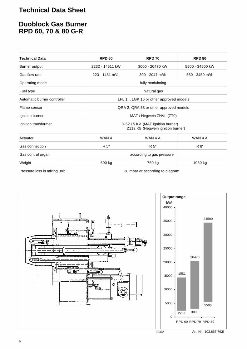
14511
20470
34500
2232 3000
5500
0
5000
10000
15000
20000
25000
30000
35000
40000
RPD 60 RPD 70 RPD 80
kW
Output range
Art. Nr.: 102.867.762902/02
Actuator
2232 - 14511 kW
RPD 60
223 - 1451 m³/h
fully modulating
Natural gas
LFL 1. , LGK 16 or other approved models
QRA 2, QRA 53 or other approved models
MAT / Hegwein ZNVL (ZT0)
D-52 L5 KVZ112 K5
R 5"
600 kg
30 mbar or according to diagram
according to gas pressure
(MAT ignition burner) (Hegwein ignition burner)
WAN 4
3000 - 20470 kW
RPD 70
300 - 2047 m³/h
R 5"
760 kg
WAN 4 A
5500 - 34500 kW
RPD 80
550 - 3450 m³/h
R 8"
1060 kg
WAN 4 A
Technical Data Sheet
Duoblock Gas BurnerRPD 60, 70 & 80 G-R
7
D4
L6 50%
G
L4 100%
T1 444
P1
P2
Y
X
Z
P4
P3
RPD 20 - 60
H2
D1
H3
H4
T2
T 3
V
D7A1D2
D5
100
%
D6
50%
H1
B3 B4W
15°
D2D2
Stift MGewinde
Länge K
D3 D3
B8
Bohrungen Kesselplatte
22,5 ° 22,5 °
15°
RPD 70 - 100
R
T
RPD A1 B1 B2 B3 B4 B5 B6 B8 D1 D2 D3 D4 D5 D6 D7 G H1 H2 H3 H4 K L1 L4
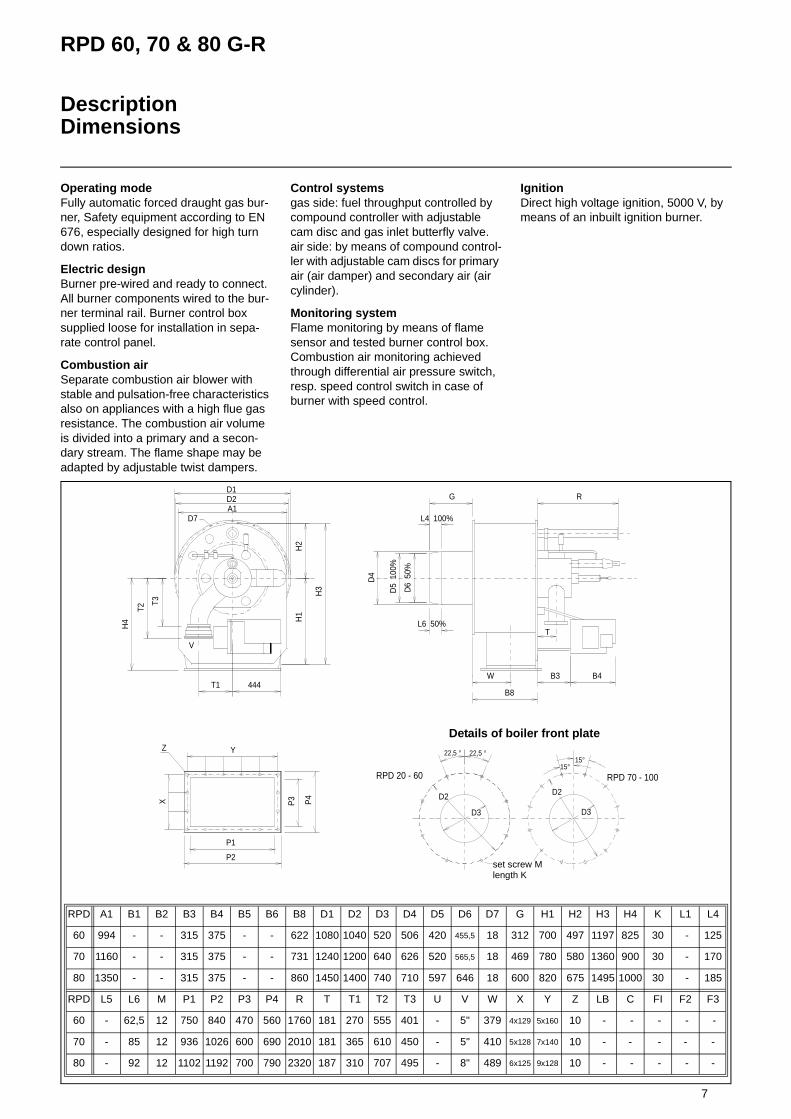
60 994 - - 315 375 - - 622 1080 1040 520 506 420 455,5 18 312 700 497 1197 825 30 - 125
70 1160 - - 315 375 - - 731 1240 1200 640 626 520 565,5 18 469 780 580 1360 900 30 - 170
80 1350 - - 315 375 - - 860 1450 1400 740 710 597 646 18 600 820 675 1495 1000 30 - 185
RPD L5 L6 M P1 P2 P3 P4 R T T1 T2 T3 U V W X Y Z LB C FI F2 F3
60 - 62,5 12 750 840 470 560 1760 181 270 555 401 - 5" 379 4x129 5x160 10 - - - - -
70 - 85 12 936 1026 600 690 2010 181 365 610 450 - 5" 410 5x128 7x140 10 - - - - -
80 - 92 12 1102 1192 700 790 2320 187 310 707 495 - 8" 489 6x125 9x128 10 - - - - -
RPD 60, 70 & 80 G-R
DescriptionDimensions
Operating modeFully automatic forced draught gas bur-ner, Safety equipment according to EN 676, especially designed for high turn down ratios.
Electric design Burner pre-wired and ready to connect. All burner components wired to the bur-ner terminal rail. Burner control box supplied loose for installation in sepa-rate control panel.
Combustion airSeparate combustion air blower with stable and pulsation-free characteristics also on appliances with a high flue gas resistance. The combustion air volume is divided into a primary and a secon-dary stream. The flame shape may be adapted by adjustable twist dampers.
Control systemsgas side: fuel throughput controlled by compound controller with adjustable cam disc and gas inlet butterfly valve.air side: by means of compound control-ler with adjustable cam discs for primary air (air damper) and secondary air (air cylinder).
Monitoring systemFlame monitoring by means of flame sensor and tested burner control box. Combustion air monitoring achieved through differential air pressure switch, resp. speed control switch in case of burner with speed control.
IgnitionDirect high voltage ignition, 5000 V, by means of an inbuilt ignition burner.
set screw Mlength K
Details of boiler front plate

8
Technical Data Sheet
Gas Duoblock Burner
Feld52:RPD 90 / 100 G-R
Technical Data
Gas flow rate
Operating mode
Fuel type
Automatic burner controller
Flame sensor
Ignition burner
Ignition transformer
Gas connection
Weight
Pressure loss in mixing unit
Gas control organ
Burner output
42000
45000
7000 7000
0
5000
10000
15000
20000
25000
30000
35000
40000
45000
50000
RPD 90 RPD 100
kW
Output range
Art. Nr.: 102.867.763002/02
Actuator
7000 - 42000 kW
RPD 90
700 - 4200 m³/h
fully modulating
Natural gas
LFL 1. , LGK 16 or other approved models
QRA 2, QRA 53 or other approved models
MAT / Hegwein ZNVL (ZT0)
D-52 L5 KVZ112 K5
R 8"
1200 kg
30 mbar or according to diagram
according to gas pressure
(MAT ignition burner) (Hegwein ignition burner)
WAN 5 A
7000 - 45000 kW
RPD 100
700 - 4500 m³/h
R 8"
1250 kg
WAN 5 A
Technical Data Sheet
Duoblock Gas BurnerRPD 90 & 100 G-R

9
RPD 90 & 100 G-R
DescriptionDimensions
Operating modeFully automatic forced draught gas bur-ner, Safety equipment according to EN 676, especially designed for high turn down ratios.
Electric design Burner pre-wired and ready to connect. All burner components wired to the bur-ner terminal rail. Burner control box supplied loose for installation in sepa-rate control panel.
Combustion airSeparate combustion air blower with stable and pulsation-free characteristics also on appliances with a high flue gas resistance. The combustion air volume is divided into a primary and a secon-dary stream. The flame shape may be adapted by adjustable twist dampers.
Control systemsgas side: fuel throughput controlled by compound controller with adjustable cam disc and gas inlet butterfly valve.air side: by means of compound control-ler with adjustable cam discs for primary air (air damper) and secondary air (air cylinder).
Monitoring systemFlame monitoring by means of flame sensor and tested burner control box. Combustion air monitoring achieved through differential air pressure switch, resp. speed control switch in case of burner with speed control.
IgnitionDirect high voltage ignition, 5000 V, by means of an inbuilt ignition burner.
D4
L6 50%
G
L4 100%
T1 444
P1
P2
Y
X
Z
P4
P3
RPD 20 - 60
H2
D1
H3
H4
T2
T3
V
D7A1D2
D5
100
%
D6
50%
H1
B3 B4W
15°
D2D2
Stift MGewinde
Länge K
D3 D3
B8
Bohrungen Kesselplatte
22,5 ° 22,5 °
15°
RPD 70 - 100
R
T
RPD A1 B1 B2 B3 B4 B5 B6 B8 D1 D2 D3 D4 D5 D6 D7 G H1 H2 H3 H4 K L1 L4
90 1700 - - 420 375 - - 890 1800 1750 883 870 675 - 18 810 905 850 1755 1100 30 - 190
100 1700 - - 420 375 - - 890 1800 1750 935 920 830 - 18 810 905 850 1755 1100 30 - 190
RPD L5 L6 M P1 P2 P3 P4 R T T1 T2 T3 U V W X Y Z LB C FI F2 F3
90 - - 12 1300 1390 742 832 2720 224 310 832 620 - 8" 494 6x132 10x135 10 - - - - -
100 - - 12 1300 1390 742 832 2720 224 310 832 620 - 8" 494 6x132 10x135 10 - - - - -
set screw Mlength K
Details of boiler front plate
10
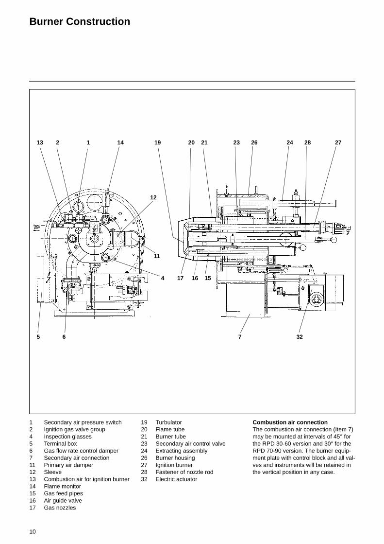
Burner Construction
1 Secondary air pressure switch2 Ignition gas valve group4 Inspection glasses5 Terminal box6 Gas flow rate control damper7 Secondary air connection11 Primary air damper12 Sleeve13 Combustion air for ignition burner14 Flame monitor15 Gas feed pipes16 Air guide valve17 Gas nozzles
19 Turbulator20 Flame tube21 Burner tube23 Secondary air control valve24 Extracting assembly26 Burner housing27 Ignition burner28 Fastener of nozzle rod32 Electric actuator
Combustion air connectionThe combustion air connection (Item 7) may be mounted at intervals of 45° for the RPD 30-60 version and 30° for the RPD 70-90 version. The burner equip-ment plate with control block and all val-ves and instruments will be retained in the vertical position in any case.
13 2 1 14 19 20 21 23 26 24 28 27
12
11
4 17 16 15
5 6 7 32

11
Mounting the Burner to the Boiler
The burner plate of the boiler must be fabricated to the specified dimensions. Mount the burner to the boiler with its insulation backing. Apply a layer to gra-phite or similar lubricant to the bolts and tighten by equal amounts. Mixing igni-tion units extended in length are availa-ble for boilers requiring a specific installation depth of the burner flame tube.
Refer to the drawing for the mounting dimensions of the burner and air duct and exhaust gas connection, if any.
Boiler liningThe boiler lining must consist of heat-resistant materials (temperature resi-stance >1400°C).
Take care that the burner flame tube is covered by the boiler lining over its full lenght.
The space between the burner flame tube and lining is packed with mineral wool.
Burner mounting inspection1. Check the mixing ignition unit
according to the boiler output.2. Adjust the pilot burner.3. Refer to the dimensioned drawing
for adjusting the mixing ignition unit.
Boiler lining
Burner flange sealing
Mineral wool
Bu
rner
Insulation
Boiler plate
Mounting bracket
Textile compensator
Air duct
Combustion air fan
Baseframe to anti-vibration mounting
12
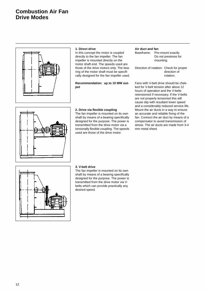
Combustion Air FanDrive Modes
1. Direct driveIn this concept the motor is coupled directly to the fan impeller. The fan impeller is mounted directly on the motor shaft end. The speeds used are those of the drive motors only. The bea-ring of the motor shaft must be specifi-cally designed for the fan impeller used.
Recommendation: up to 10 MW out-put
2. Drive via flexible couplingThe fan impeller is mounted on its own shaft by means of a bearing specifically designed for the purpose. The power is transmitted from the drive motor via a torsionally flexible coupling. The speeds used are those of the drive motor.
3. V-belt driveThe fan impeller is mounted on its own shaft by means of a bearing specifically designed for the purpose. The power is transmitted from the drive motor via V-belts which can provide practically any desired speed.
Air duct and fanBaseframe: Pre-mount exactly.
Do not prestress for mounting.
Direction of rotation: Check for properdirection of rotation.
Fans with V-belt drive should be chek-ked for V-belt tension after about 12 hours of operation and the V-belts retensioned if necessary. If the V-belts are not properly tensioned this will cause slip with resultant lower speed and a considerably reduced service life.Mount the air ducts in a way to ensure an accurate and reliable fixing of the fan. Connect the air duct by means of a compensator to avoid transmission of stress. The air ducts are made from 3-4 mm metal sheet.
13
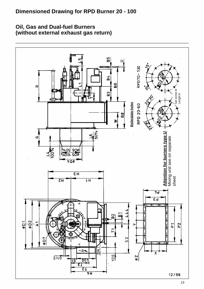
Dimensioned Drawing for RPD Burner 20 - 100
Oil, Gas and Dual-fuel Burners(without external exhaust gas return)
Bo
ilerp
late
ho
les S
et s
crew
MLe
nght
K
Att
enti
on
fo
r b
urn
ers
typ
e U
Mix
ing
unit
see
on s
epar
ate
shee
t

14 Dimensions of RPD Burner 20 - 100Oil, Gas and Dual-fuel burners(without external exhaust gas return)
*) Note: If longer flame tubes are used, the extended lenght must be added to the dimensiones G, R, L5
**) D4 = burner tube outside diameter***) Flange acc. to DIN 2631 for RPD 20 to 70, and acc. to DIN 2633 for RPD 80, 90 and 100
RPD A1 B1 B2 B3 B4 B5 B6 B8 D1 D2 D3 D4 D5 D6 D7 G H1 H2 H3 H4 K L1 L4 L5
**) 100% 50% *) MAT DG75 100% *)
20 530 53 29 90 314 91 560 325 530 500 270 260 210 - 12 250 385 265 650 425 30 465 - 68 780
30 745 78 19 260 375 70 705 416 830 790 385 371 290 323 17,5 317 620 373 993 650 30 550 700 124 1350
40 745 78 19 260 375 70 705 416 830 790 423 409 340 367 17,5 442 620 373 993 650 30 550 700 95 1425
50 950 78 19 315 375 70 760 535 1030 990 470 456 380 410 17,5 370 675 475 1150 740 30 600 770 110 1620
60 994 78 19 315 375 70 760 622 1080 1040 520 506 420 455 18 312 700 497 1197 825 30 650 735 125 1695
70 1160 78 19 315 375 75 765 731 1240 1200 640 626 520 565 18 469 780 580 1360 900 30 740 - 170 1995
80 1350 75 19 315 375 75 765 860 1450 1400 740 710 597 646 18 600 820 675 1495 1000 30 700 - 185 2285
90 1700 75 3 420 375 75 870 890 1800 1750 883 870 675 - 18 810 905 850 1755 1100 30 745 - 190 2585
100 1700 75 3 420 375 75 870 890 1800 1750 945 922 830 - 18 810 905 850 1755 1100 30 745 - 190 2585
RPD L6 M P1 P2 P3 P4 R S1 S2 T T1 T2 T3 U DN W X Y Z
50% *) ***)
20 - 10 430 510 236 316 - - - 112 150 240 - 18x1,5 50 190 2x143 4x120 10
30 62 12 580 670 320 410 1265 140 497 160 192 491 346 22x1,5 80 248 4x92 5x126 10
40 50 12 580 670 320 410 1265 140 497 160 192 491 346 22x1,5 80 248 4x92 5x126 10
50 55 12 740 830 416 506 1743 115 595 181 250 530 376 22x1,5 125 319 3x152 5x156 10
60 62 12 750 840 470 560 1760 195 622 181 270 555 401 22x1,5 125 379 4x129 5x160 10
70 85 12 936 1026 600 690 2010 270 705 181 365 610 450 28x1,5 125 410 5x128 7x140 10
80 92 12 1102 1192 700 790 2320 310 800 187 310 707 495 28x1,5 200 489 6x125 9x128 10
90 - 12 1300 1390 742 832 2720 240 845 224 310 832 620 28x1,5 200 494 6x132 10x135 10
100 - 12 1300 1390 742 832 2720 240 845 224 310 832 620 28x1,5 200 494 6x132 10x135 10
15
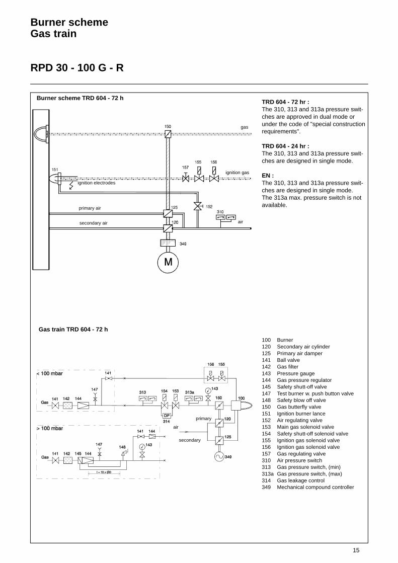
Burner schemeGas train
RPD 30 - 100 G - R
TRD 604 - 72 hr :The 310, 313 and 313a pressure swit-ches are approved in dual mode or under the code of "special construction requirements".
TRD 604 - 24 hr :The 310, 313 and 313a pressure swit-ches are designed in single mode.
EN :The 310, 313 and 313a pressure swit-ches are designed in single mode. The 313a max. pressure switch is not available.
100 Burner120 Secondary air cylinder125 Primary air damper141 Ball valve142 Gas filter143 Pressure gauge144 Gas pressure regulator145 Safety shutt-off valve147 Test burner w. push button valve148 Safety blow off valve150 Gas butterfly valve151 Ignition burner lance152 Air regulating valve153 Main gas solenoid valve154 Safety shutt-off solenoid valve155 Ignition gas solenoid valve156 Ignition gas solenoid valve157 Gas regulating valve310 Air pressure switch313 Gas pressure switch, (min)313a Gas pressure switch, (max)314 Gas leakage control349 Mechanical compound controller
Gas train TRD 604 - 72 h
air
secondary
primary
Burner scheme TRD 604 - 72 h
gas
ignition electrodes
air
primary air
secondary air
ignition gas

16
Mounting PositionLeak TestIgnition Gas ConnectionIgnition Burner Type ZT0
Mounting positionGas pressure regulators and valves can be mounted in vertical lines in any posi-tion within the 360° range. In horizontal lines they must not be mounted over-head and only 180° in the upper sector. The ball valve and filter can be mounted in any desired position. Take care that the housing does not make contact with the wall and is clear by minimum 20 mm. Do not use the spring bolt of the regulator and the solenoid elements of the valves as levers.
Leak testCheck the screwed joints and flanged connections for absence of leaks. The leak test of the joints should be made under pressure using only foaming agents approved by DVGW and not causing corrosion.
Electrical wiring of gas valvesCheck that the data given on the name-plate of the gas valves agree with the mains voltage.Open the terminal box of the valve. Feed the connection cable through the screwed union (conduit thread Pg 13.5) and connect the terminals marked accordingly.L = phaseN = zero conductor = protective conductor (green-yellow)
Disconnectable jointAn easy-to-disconnect joint with flat sealing (e.g. compensator) should be provided to allow the boiler door to be swivelled out if required for mainte-nance work on the boiler (furnace chamber). This compensator should also be designed to accommodate the axial or lateral expansion and absorb vibrations.
Ignition gas connectionAn ignition burner is used to ignite the main gas flame. The ignition gas line is branched out of the gas control group between the two gas valves and instal-led to the ignition burner on the shortest possible way. In the case of oil and dual-fuel burners the burner is ignited with propane supplied through a sepa-rate R „ propane connection. The igni-tion gas flow rate may be adjusted on the volumetric flow control valve of the ignition gas valve or directly on the igni-tion gas burner. The required gas pres-sure for the ignition gas burner is 50-150 mbar. It is advisable to install a gas pressure regulator upstream of the igni-tion gas burner. The air pressure for the ignition gas burner should be between 10 and 30 mbar. The boiler back pres-sure shall not be taken into account. The air pressure should be adjusted in accordance with the gas pressure to ensure an undelayed ignition and a good flame pattern.
1 Transformer unit with built-in ignition transformer
2 Electrical angular plug connector3 Gas connection, may be
connected on either side right and left with gas test socket
4 Air connection, mounted to transformer unit
5 Air test socket6 Igniter tube, mounted to air flange
7 Spacer ring8 Ignition electrode connection rods9 Gas tube10 Ignition electrode connection rods11 Gas nozzle for natural gas or
propane12 Mixing chamber
* The outside diameter will be 50 mm for tube lengths above 4000 mm and for all high-grade steel tubes.
Mounting flangeView A
Gas RP1/2normally left
Air Rp1Ignition Burner Type ZT0

17
Ignition Burner Type ZT0
Technical Data
Construction according to sectional drawingThe igniter consists mainly of the trans-former unit (Item 1) housing the ignition transformer, the igniter tube with air and mounting flange (Item 6), a gas tube (9) with nozzle (11) and the electrode car-rier ring (10). The igniter tube with the Rp1 air connection is bolted to the transformer unit. After the 4 bolts (Item 4) have been unscrewed it may be removed or turned by 90° if required by the position of the air connection. When turning the tubes care must be taken not to change the position of the inner supporting rings and rods because this might lead to operational trouble. The gas supply may be connected eit-her to the left-hand or right-hand ope-ning. The opening not used is closed with a screw plug which also carries the screw-in gas test socket (3). The elec-trode support ring (Item 10) is mounted to the end of the gas tube.
The ionization electrode and ignition electrode are extended with connecting rods (Item 8). These rods are installed through the bottom of the transformer housing in 2 ceramic insulators and car-ried by intermediate supporting rings (Item 7) spaced at 300 mm.
Flame monitorAn ionization electrode is provided for flame monitoring. The flame signal is generated by d.c. current which due to the ionization effect and the rectifier effect of the flame is caused to flow from the igniter tube earth via the flame to the ionization electrode and via the con-necting rod to the amplifier in the auto-matic furnace controller. The ionization electrode and ignition electrodes are adjusted in accordance with the dra-wing.
When installing new electrodes these must be bent, cut to length and adjusted as required. The internal resistance of the ionization system amounts to some megohms. Such a high resistance ensures a good insulating capacity of the electrodes and connecting rods. In a dust-laden com-bustion air environment it is therefore important to clean the insulators at shor-ter intervals. Humidity should be kept out. See also electrical function. The ceramic insulator of the ionization electrode must not be allowed to heat up above 500 °C because this could lead to shutdown on trouble. Therefore, a minimum air flow rate (10-20 % of the full-load rate) should be allowed to flow if this temperature is likely to be rea-ched by radiation or convection with the furnace chamber in hot condition and the burner flame turned off.
Technical data of ignition gas burner type ZT0
Fuel gases according to G 260Flame power max. 120 kWFlame length max. 600 mmGas connection Rp 1/2 right or leftAir connection Rp 1, may be turned by 4x90°Air flow rate max. 50 m³/hAir index 0.3-0.5; remaining air rate must be available from furnace chamberMax. ambient temperature 500°C in tube; if temperature is higher, keep combustion air
connected partly as cooling air; 0°C to +60°C in transformer unit
Transformer unit
Connection voltage 230 V, 50 HzConnector type plug connectorPower input ignition transformer 100 VA, 20% duty cycle (with thermal winding shield)
ignition 5 kV (2-3 seconds via automatic furnace controller)Ambient temperature 0°C to +60°CDegree of protection IP 54
Electrical connection
Cl. 1 (Mp)Cl. 8 (Ph) ignition transfer, primary Use shielded cable Z 912 F 00 for flame feedback.Cl. 10 ionization signal NOTE: The shield must not make contact with earth.

18
Ignition Burner Type ZT0
Gas Pressure AdjustmentParts List
Gas pressure adjustmentIn standard version the igniters are sui-table for a working range 50-150 mbar. If a higher gas pressure is required in the customer’s order, the two threaded gas inlet connections will be fitted with restrictors by the manufacturer already. The igniter will in this way be adjusted to the pressure above 150 mbar.If the higher inlet pressure is recognized at a later stage only, a restriction to maximum 150 mbar can also be achie-ved by means of a ball valve, for example.
Characteristicline Gas type Nozzle holes Flame length
P Propane 1x2,5 + 6x1,0 approx. 600 mm
M Natural gas 1x4,0 + 6x1,3 approx. 500 mm
N City gas 1x5,0 + 8x2,3 approx. 500 mm
Parts list
Item. Qty. Description Part No. Material
1 1 Transformer unit Z 112 K 5 Housing of GAL
2 1 Right-angle plug with 2 unions A 5 Z 1 10-pole, max. 2.5
3 1 Gas test socket Z 138 Z 2 Ms 58
4 4 Hexagon socket head screw W 826 F 10
5 1 Air test socket Z 138 Z 1 Ms 58
6 1 Igniter tube with rolled-in mixing chamber and mounting flange with Rp1 air inlet thread
Z 1050 Z...** GAL / steel
7 * Intermediate supporting ring with 2 ceramic insulators Z 545 F11
Z 960 K 4 St VII 23
8 2 Connecting rods Z 781 F...** Zinc-plated steel
9 1 Gas tube Z 521 F...** St 35
10 1 Electrode carrier ring Z 960 K 13 St VII 23
11 1 Gas nozzle Natural gasPropaneCity gas
Z 330 F 4013Z 330 F 2510Z 985 F 1
High-grade steel 1. 4104High-grade steel 1. 4104High-grade steel 1. 4104
12 - Mixing chamber with mixing ring Included in Item 6
High-grade steel, heat-resistant
* Quantity depends on pipe length: 3 intermediate rings per metre of tube length.** Additional data according to type (tube length).
19
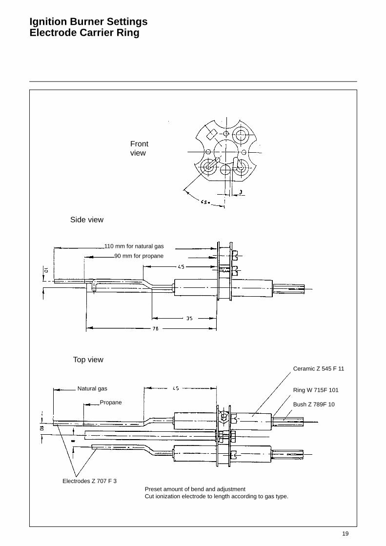
Ignition Burner SettingsElectrode Carrier Ring
Frontview
Side view
110 mm for natural gas
90 mm for propane
Top view
Natural gas
Propane
Electrodes Z 707 F 3
Ceramic Z 545 F 11
Ring W 715F 101
Bush Z 789F 10
Preset amount of bend and adjustmentCut ionization electrode to length according to gas type.

20
Ignition Gas Solenoid Valve
Type MVD 505 / 5 single-stage
Technical data:Nominal bore: R1/2“Max. operating pressure: 500 mbarOpening time: < 1 secClosing time: < 1 secAmbient temperature:-15°C to +60°CMounting position: solenoid in upright
position vertical to horizontal
Voltage/frequency: (AC) 230 V(+10% -15%)
Duty factor: 100% CDDegree of protection: IP 54, IP 65Power rating: 15 VA
Main flow rate adjustertype series MVDUnscrew the protective cap and remove the lock nut to allow the main flow rate to be adjusted. The main flow rate adju-ster is supplied ex works in fully opened position. Turning clockwise will reduce the gas flow rate.Turning counterclockwise will increase the gas flow rate.After having adjusted the flame control on the gas burner make sure to tighten the lock nut again. Screw on the protec-tive cap again.
InstallationWhen installing the valve in the pipeline take care to observe the arrow on the valve housing and the required moun-ting position. For screwing the pipeline into the valve housing do not use the magnet as a lever but apply a suitable tool against the valve housing.After installation make a test for absence of leaks and proper operation.
Solenoid replacementtype series MV, MVDDisconnect the electrical terminals; remove the screw cap; lift off the sole-noid. For installation proceed in reverse order.
Electrical connectionFeed in the cable through cable union (conduit thread Pg 11). Make the electri-cal connection by means of the screw terminals in the terminal box of the sole-noid housing.Take care to observe the connection diagram.
1 Cable union2 Electric terminal box3 Solenoid4 Housing5 Screen6 Valve seat7 Connector for
earthing contact K01/1
8 Valve disk9 Mud guard10 Closing compression spring11 Anchor12 Main flow rate adjuster13 Lock nut14 Protective cap
Protective cap
Notacceptable
21
Burner Electrical Connection
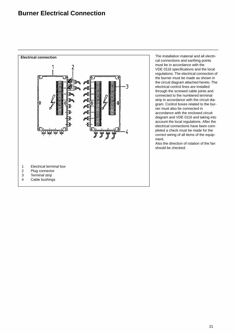
The installation material and all electri-cal connections and earthing points must be in accordance with the VDE 0116 specifications and the local regulations. The electrical connection of the burner must be made as shown in the circuit diagram attached hereto. The electrical control lines are installed through the screwed cable joints and connected to the numbered terminal strip in accordance with the circuit dia-gram. Control boxes related to the bur-ner must also be connected in accordance with the enclosed circuit diagram and VDE 0116 and taking into account the local regulations. After the electrical connections have been com-pleted a check must be made for the correct wiring of all items of the equip-ment. Also the direction of rotation of the fan should be checked.
1 Electrical terminal box2 Plug connector3 Terminal strip4 Cable bushings
Electrical connection

22
Dimensions of the Mixing Unit(standard versions)
RPD 30 - RPD 80
RPD 30 RPD 40
RPD 50 RPD 60
RPD 70 RPD 80
23
Draw-out and Swing Mechanism
Burner Settings
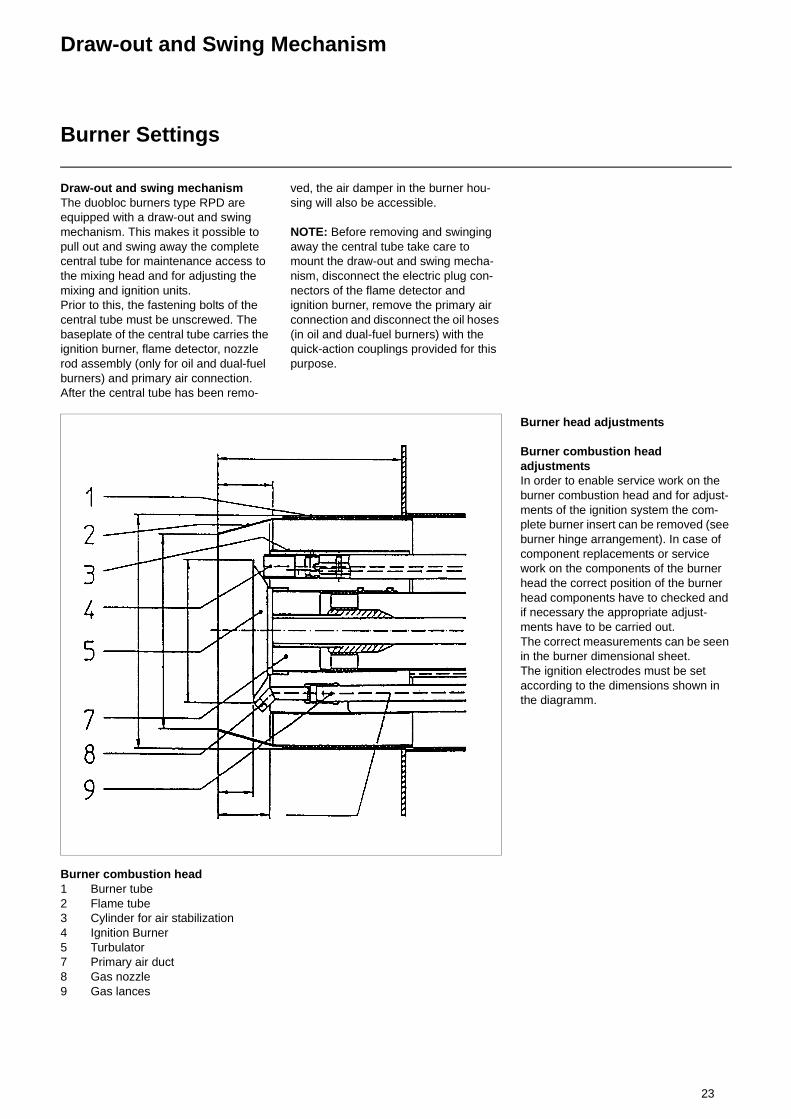
Draw-out and swing mechanismThe duobloc burners type RPD are equipped with a draw-out and swing mechanism. This makes it possible to pull out and swing away the complete central tube for maintenance access to the mixing head and for adjusting the mixing and ignition units. Prior to this, the fastening bolts of the central tube must be unscrewed. The baseplate of the central tube carries the ignition burner, flame detector, nozzle rod assembly (only for oil and dual-fuel burners) and primary air connection. After the central tube has been remo-
ved, the air damper in the burner hou-sing will also be accessible.
NOTE: Before removing and swinging away the central tube take care to mount the draw-out and swing mecha-nism, disconnect the electric plug con-nectors of the flame detector and ignition burner, remove the primary air connection and disconnect the oil hoses (in oil and dual-fuel burners) with the quick-action couplings provided for this purpose.
Burner head adjustments
Burner combustion head adjustmentsIn order to enable service work on the burner combustion head and for adjust-ments of the ignition system the com-plete burner insert can be removed (see burner hinge arrangement). In case of component replacements or service work on the components of the burner head the correct position of the burner head components have to checked and if necessary the appropriate adjust-ments have to be carried out.The correct measurements can be seen in the burner dimensional sheet.The ignition electrodes must be set according to the dimensions shown in the diagramm.
Burner combustion head1 Burner tube2 Flame tube3 Cylinder for air stabilization4 Ignition Burner5 Turbulator7 Primary air duct8 Gas nozzle9 Gas lances
24
Air Flow AdjustmentGas Rate Adjustment
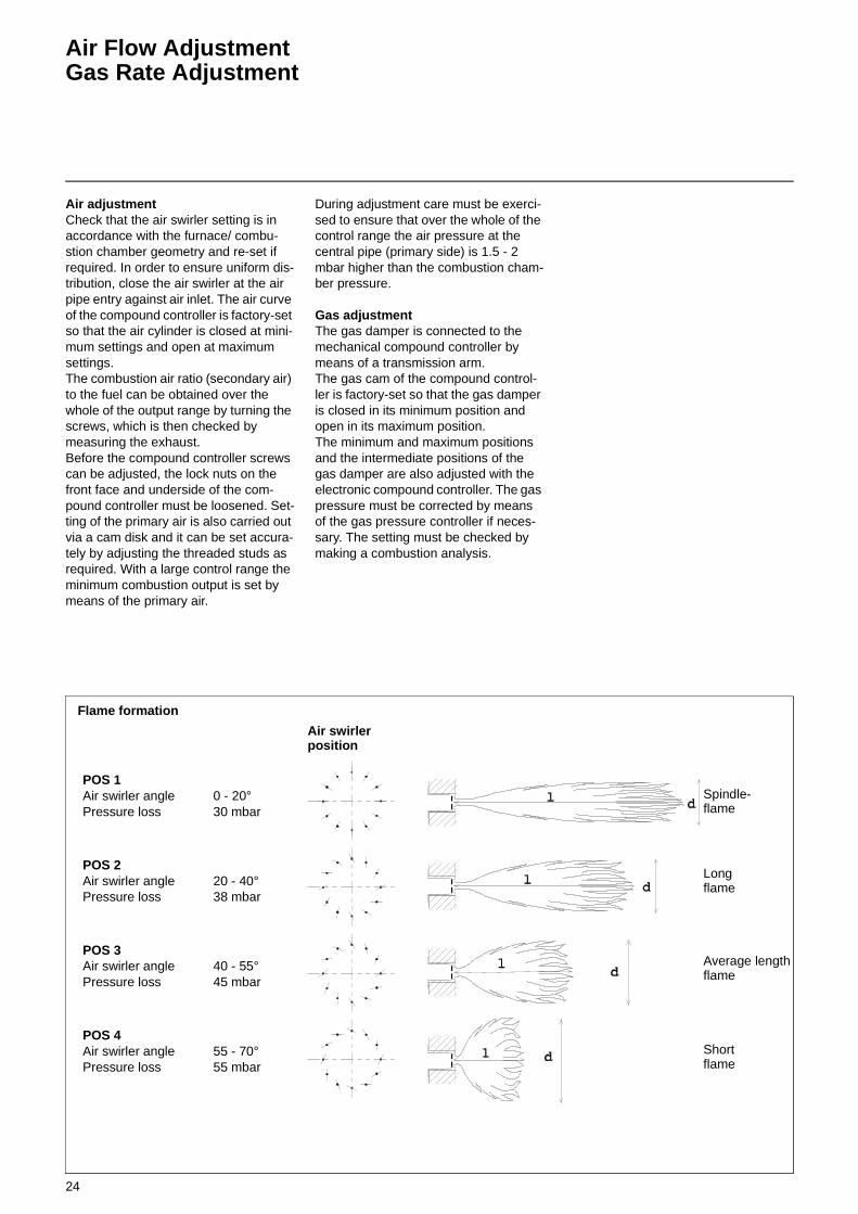
Air adjustmentCheck that the air swirler setting is in accordance with the furnace/ combu-stion chamber geometry and re-set if required. In order to ensure uniform dis-tribution, close the air swirler at the air pipe entry against air inlet. The air curve of the compound controller is factory-set so that the air cylinder is closed at mini-mum settings and open at maximum settings.The combustion air ratio (secondary air) to the fuel can be obtained over the whole of the output range by turning the screws, which is then checked by measuring the exhaust.Before the compound controller screws can be adjusted, the lock nuts on the front face and underside of the com-pound controller must be loosened. Set-ting of the primary air is also carried out via a cam disk and it can be set accura-tely by adjusting the threaded studs as required. With a large control range the minimum combustion output is set by means of the primary air.
During adjustment care must be exerci-sed to ensure that over the whole of the control range the air pressure at the central pipe (primary side) is 1.5 - 2 mbar higher than the combustion cham-ber pressure.
Gas adjustmentThe gas damper is connected to the mechanical compound controller by means of a transmission arm.The gas cam of the compound control-ler is factory-set so that the gas damper is closed in its minimum position and open in its maximum position.The minimum and maximum positions and the intermediate positions of the gas damper are also adjusted with the electronic compound controller. The gas pressure must be corrected by means of the gas pressure controller if neces-sary. The setting must be checked by making a combustion analysis.
Spindle-flame
Longflame
Average lengthflame
Shortflame
Air swirler position
Flame formation
POS 1Air swirler angle Pressure loss
0 - 20°30 mbar
POS 2Air swirler angle Pressure loss
20 - 40°38 mbar
POS 3Air swirler angle Pressure loss
40 - 55°45 mbar
POS 4Air swirler angle Pressure loss
55 - 70°55 mbar
25
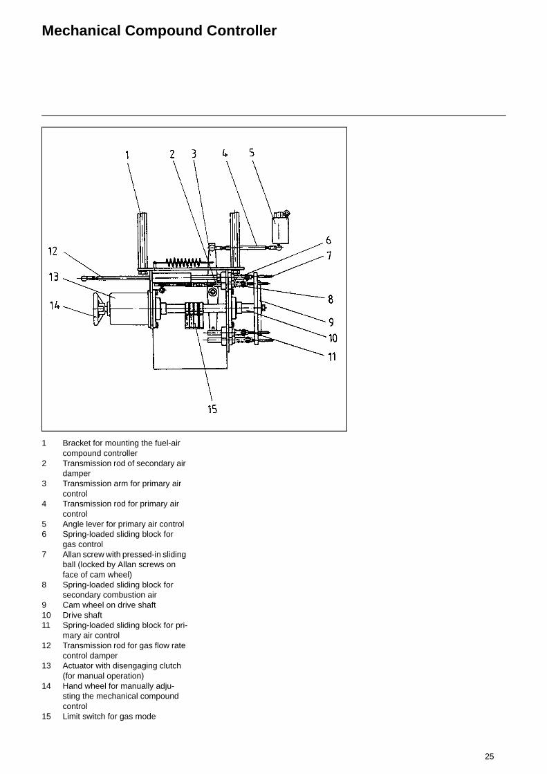
Mechanical Compound Controller
1 Bracket for mounting the fuel-air compound controller
2 Transmission rod of secondary air damper
3 Transmission arm for primary air control
4 Transmission rod for primary air control
5 Angle lever for primary air control6 Spring-loaded sliding block for
gas control7 Allan screw with pressed-in sliding
ball (locked by Allan screws on face of cam wheel)
8 Spring-loaded sliding block for secondary combustion air
9 Cam wheel on drive shaft10 Drive shaft11 Spring-loaded sliding block for pri-
mary air control12 Transmission rod for gas flow rate
control damper13 Actuator with disengaging clutch
(for manual operation)14 Hand wheel for manually adju-
sting the mechanical compound control
15 Limit switch for gas mode
26
Adjusting Instructions
Gas Pressure SwitchAir Pressure Switch
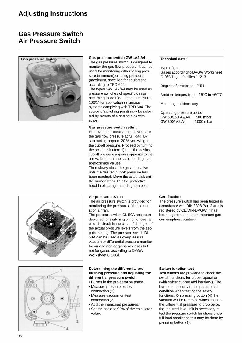
Gas pressure switch GW...A2/A4The gas pressure switch is designed to monitor the gas flow pressure. It can be used for monitoring either falling pres-sure (minimum) or rising pressure (maximum, specified for equipment according to TRD 604). The types GW...A2/A4 may be used as pressure switches of specific design according to VdTÜV Leaflet "Pressure 100/1" for application in furnace systems complying with TRD 604. The setpoint (switching point) may be selec-ted by means of a setting disk with scale.
Gas pressure switch setting Remove the protective hood. Measure the gas flow pressure at full load. By subtracting approx. 20 % you will get the cut-off pressure. Proceed by turning the scale disk (item 1) until the desired cut-off pressure appears opposite to the arrow. Note that the scale readings are approximate values. Then slowly close the gas stop valve until the desired cut-off pressure has been reached. Move the scale disk until the burner stops. Put the protective hood in place again and tighten bolts.
Verbundregler für EK 7 - 9 G-R/RUGas pressure switch Technical data:
Type of gas:Gases according to DVGW Worksheet G 260/1, gas families 1, 2, 3
Degree of protection: IP 54
Ambient temperature: -15°C to +60°C
Mounting position: any
Operating pressure up to:GW 50/150 A2/A4 500 mbarGW 500/ A2/A4 1000 mbar
Air pressure switchThe air pressure switch is provided for monitoring the pressure of the combu-stion air fan. The pressure switch DL 50A has been designed for switching on, off or over an electric circuit in the case of changes of the actual pressure levels from the set-point setting. The pressure switch DL 50A can be used as overpressure, vacuum or differential pressure monitor for air and non-aggressive gases but not for gases according to DVGW Worksheet G 260/l.
Determining the differential pre-flushing pressure and adjusting the differential pressure switch• Burner in the pre-aeration phase.• Measure pressure on test
connection (2).• Measure vacuum on test
connection (3).• Add the measured pressures.• Set the scale to 90% of the calculated
value.
CertificationThe pressure switch has been tested in accordance with DIN 3398 Part 2 and is registered by CE/DIN-DVGW. It has been registered in other important gas consumption countries.
Switch function testTest buttons are provided to check the switch functions for proper operation (with safety cut-out and interlock). The burner is normally run in partial-load condition when testing the safety functions. On pressing button (4) the vacuum will be removed which causes the differential pressure to drop below the required level. If it is necessary to test the pressure switch functions under full-load conditions this may be done by pressing button (1).
27
Setting Pressure Switches and Control System
Setting of the air pressure switchThe differential pressure between bur-ner housing (overpressure) and air box (subatmospheric pressure) is measured with the burner in full-load condition. The pressure setting of the air pressure switch must therefore be smaller than the differential pressure measured. For adjustment, remove the protective hood and turn the setting scale accordingly.
Switching functions of air pressure switch/gas pressure switchWith increasing pressure:
P1 opensP2 closes
With decreasing pressure:P1 closesP2 opens
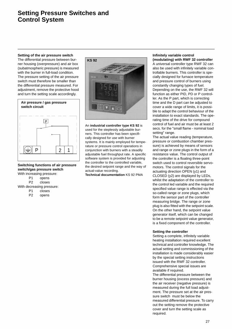
An industrial controller type KS 92 is used for the steplessly adjustable bur- ners. This controller has been specifi- cally designed for use with burner systems. It is mainly employed for tempe-rature or pressure control operations in conjunction with burners with a steadily adjustable fuel throughput rate. A specific software system is provided for adjusting the controller to the controlled variable, the desired setpoint range and the way of actual-value recording. Technical documentation KS 92 PMA
Infinitely variable control (modulating) with RWF 32 controllerA universal controller type RWF 32 can also be used with infinitely variable con-trollable burners. This controller is spe-cially designed for furnace temperature and pressure control of burners using constantly changing types of fuel. Depending on the use, the RWF 32 will function as either PID, PD or P control-ler. As the P part, which is correcting time and the D part can be adjusted to cover a wide range of limits, it is possi-ble to adapt the control behaviour of the installation to exact standards. The ope-rating time of the drive for compound control of fuel and air must be at least 2 secs. for the "small flame - nominal load setting" range.The actual value reading (temperature, pressure or combustion chamber pres-sure) is achieved by means of sensors and range or zone plugs in the form of a resistance value. The control output of the controller is a floating three-point switch used to control reversible servo-motors. The control signals for the actuating direction OPEN (y1) and CLOSED (y2) are displayed by LEDs, whilst the adaptation of the controller to the control led variable and the required specified value range is effected via the so-called range or zone plugs, which form the sensor part of the controller measuring bridge. The range or zone plug is also fitted with the setpoint scale. On the other hand, the setpoint value generator itself, which can be changed to be a remote setpoint value generator, is a fixed component of the controller.
Setting the controllerSetting a complete, infinitely variable heating installation required excellent technical and controller knowledge. The actual setting and commissioning of the installation is made considerably easier by the special setting instructions issued with the RWF 32 controller. Comprehensive special issues are available if required.The differential pressure between the burner housing (excess pressure) and the air receiver (negative pressure) is measured during the full load adjust-ment. The pressure set at the air pres-sure switch must be below the measured differential pressure. To carry out the setting remove the protective cover and turn the setting scale as required.
P 12
P
Air pressure / gas pressure switch circuit
KS 92
28
Automatic Furnace Controller LFL 1... / LGK 16...
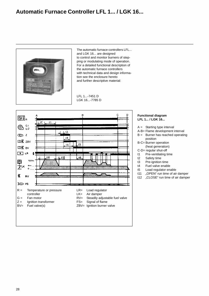
The automatic furnace controllers LFL... and LGK 16... are designed to control and monitor burners of step-ping or modulating mode of operation. For a detailed functional description of the automatic furnace controllers with technical data and design informa-tion see the enclosure hereto and further descriptive material:
LFL 1...-7451 DLGK 16...-7785 D
Functional diagramLFL 1... / LGK 16...
A = Starting type intervalA-B= Flame development intervalB = Burner has reached operating
positionB-C= Burner operation
(heat generation)C-D= regular shut-offt1 Pre-ventilating timet2 Safety timet3 Pre-ignition timet4 Fuel valve enablet5 Load regulator enablet11 „OPEN“ run time of air dampert12 „CLOSE“ run time of air damper
R = Temperature or pressurecontroller
G = Fan motorZ = Ignition transformerBV= Fuel valve(s)
LR= Load regulatorLK= Air damperRV= Steadily adjustable fuel valveFS= Signal of flameZBV= Ignition burner valve
29
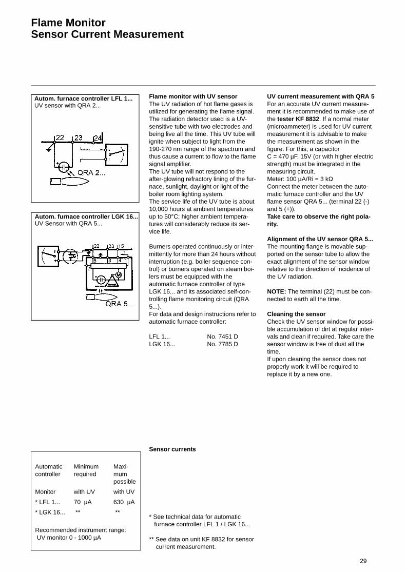
Flame MonitorSensor Current Measurement
Flame monitor with UV sensorThe UV radiation of hot flame gases is utilized for generating the flame signal.The radiation detector used is a UV-sensitive tube with two electrodes and being live all the time. This UV tube will ignite when subject to light from the 190-270 nm range of the spectrum and thus cause a current to flow to the flame signal amplifier.The UV tube will not respond to the after-glowing refractory lining of the fur-nace, sunlight, daylight or light of the boiler room lighting system.The service life of the UV tube is about 10,000 hours at ambient temperatures up to 50°C; higher ambient tempera-tures will considerably reduce its ser-vice life.
Burners operated continuously or inter-mittently for more than 24 hours without interruption (e.g. boiler sequence con-trol) or burners operated on steam boi-lers must be equipped with the automatic furnace controller of type LGK 16... and its associated self-con-trolling flame monitoring circuit (QRA 5...).For data and design instructions refer to automatic furnace controller:
LFL 1... No. 7451 DLGK 16... No. 7785 D
Sensor currents
* See technical data for automatic furnace controller LFL 1 / LGK 16...
** See data on unit KF 8832 for sensor current measurement.
UV current measurement with QRA 5For an accurate UV current measure-ment it is recommended to make use of the tester KF 8832. If a normal meter (microammeter) is used for UV current measurement it is advisable to make the measurement as shown in the figure. For this, a capacitorC = 470 µF, 15V (or with higher electric strength) must be integrated in the measuring circuit. Meter: 100 µA/Ri = 3 kΩConnect the meter between the auto-matic furnace controller and the UV flame sensor QRA 5... (terminal 22 (-) and 5 (+)).Take care to observe the right pola-rity.
Alignment of the UV sensor QRA 5...The mounting flange is movable sup-ported on the sensor tube to allow the exact alignment of the sensor window relative to the direction of incidence of the UV radiation.
NOTE: The terminal (22) must be con-nected to earth all the time.
Cleaning the sensorCheck the UV sensor window for possi-ble accumulation of dirt at regular inter-vals and clean if required. Take care the sensor window is free of dust all the time. If upon cleaning the sensor does not properly work it will be required to replace it by a new one.
Automatic controller
Minimum required
Maxi-mum possible
Monitor with UV with UV
* LFL 1... 70 µA 630 µA
* LGK 16... ** **
Recommended instrument range: UV monitor 0 - 1000 µA
Autom. furnace controller LFL 1...UV sensor with QRA 2...
Autom. furnace controller LGK 16...UV Sensor with QRA 5...

30
Actuator Type ARIS, 4, 4a, 5
DescriptionThe actuator type ARIS-N is designed as a controlling element for oil/gas or dual-fuel burners with sliding or modula-ting control concept. The actuator is equipped with a short-circuit-proof syn-chronous a.c. motor which drives a shaft via a maintenance free spur-gear unit with permanent grease lubrication. The shaft end carries a coupling for operating the controlling element for fuel and combustion air. The actuator is designed for two-wire control by control-lers or switching units with change-over contact (single-wire control is possible). A feedback potentiometer is used as a optional feature.
Technical Data:Voltage: 230 V +/- 10% Protection class: IP 54, DIN 400 50Frequency: 50 Hz (60 Hz) Installation position: no restrictionOperating time: 25 - 30 sec. at 90°Torque: WAN 4 40 Nm
WAN 4A 60 NmWAN 5 110 Nm
Weight: WAN 4 3,4 kgWAN 4a 3,4 kgWAN 5 5,8 kg
Contacts: max. 250 V 10(3) A
Ambient temperature: -15 °C till + 60 °C
AdjustmentA service switch for manual/automatic operation is provided for adjusting the actuator/controlling element.
This service switch comprises:
1x manual/automatic tumbler switch1x left/right pushbutton switch con-
nected according to the sketch (left)
For using the actuators with service switch (no handwheel) care should be taken to observe the following:
• An additional permanent phase must be installed from the actuator to the control cabinet via the terminal box or directly to the control cabinet.
• An additional terminal must be moun-ted in the terminal box.
31
Gas Connection
For the installation and taking into ope-ration of the gas lines care should be taken to observe the regulations of DVGW (German Association of the Gas and Water Sector) especially DVGW-TRGI (Technical Regulation for Gas Installations) and TRF (Technical Regu-lation for Furnaces).DIN 4756 and TRD 412 contain specifi-cations for the construction, design and safety requirements of gas furnaces in heating installations. Furnace systems of higher operating pressures are sub-ject to the DVGW Worksheets G 460 and G 461. The gas lines must meet specifications set out in DVGW-TRGI in the case of furnace systems with opera-ting pressures up to 100 mbar or above 100 mbar.
Gas control group with two gas valves and leak tester:The gas section is designed in accor-dance with EN 676 and TRD 412, two gas valves and leakage tester are prescribed for burners with a capacity above 1200 kW.The operation, mounting and adjust-ment of the valve leak testers is descri-bed in detail on a separate sheet.
Gas connection pressure:The gas line must be dimensioned in accordance with the throughput rate and the available gas pressure and installed to the burner on the shortest possible way with minimum pressure loss.To provide the most effective conditions for start-up, take care that the burner and gas stop valve are installed with the minimum possible distance between
one another. This means that the 2nd gas valve (looking in the direction of the gas flow) should be mounted in the immediate vicinity of the burner.Note the gas pressure loss of the gas control group and burner. The gas con-trol group can be connected directly to the gas feed line. Note the order in which the valves and instruments are mounted and the direction of flow. Prior to installation and taking into operation, check the valves and instruments and the connection fittings for the possible accumulation of dirt and foreign matter.
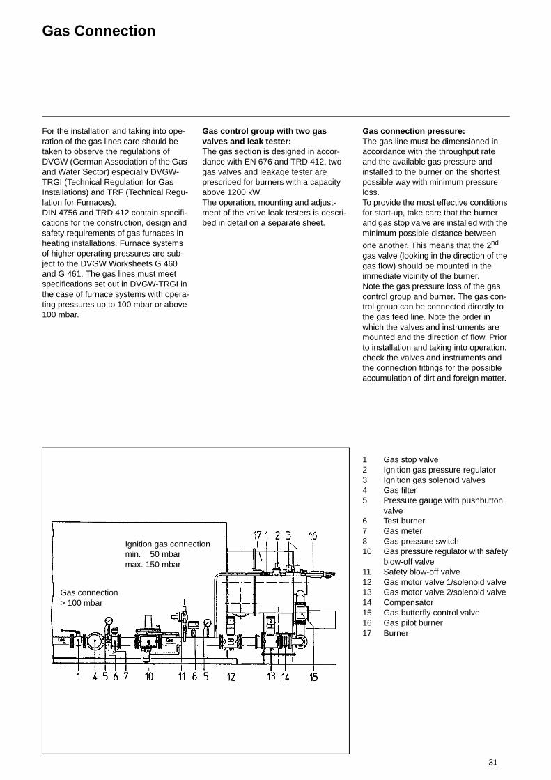
1 Gas stop valve2 Ignition gas pressure regulator3 Ignition gas solenoid valves4 Gas filter5 Pressure gauge with pushbutton
valve6 Test burner7 Gas meter8 Gas pressure switch10 Gas pressure regulator with safety
blow-off valve11 Safety blow-off valve12 Gas motor valve 1/solenoid valve13 Gas motor valve 2/solenoid valve14 Compensator15 Gas butterfly control valve16 Gas pilot burner17 Burner
Gas connection> 100 mbar
Ignition gas connectionmin. 50 mbarmax. 150 mbar
32
Gas Motor Valve VK
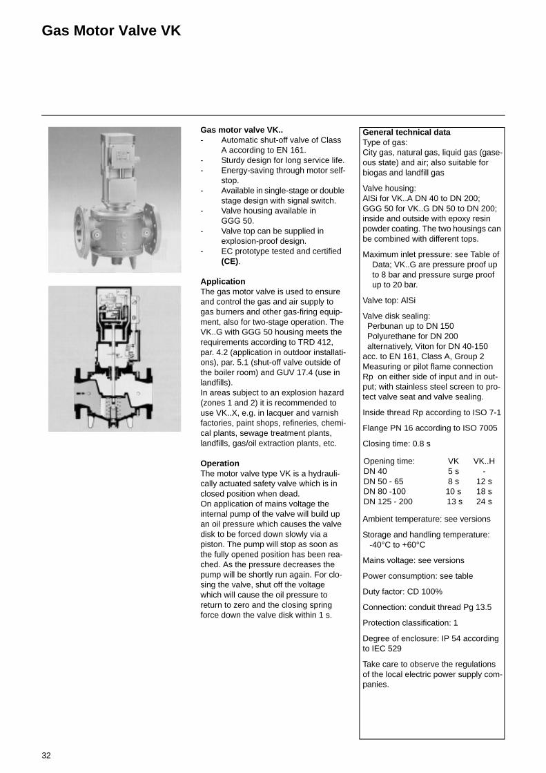
Gas motor valve VK..- Automatic shut-off valve of Class
A according to EN 161.- Sturdy design for long service life.- Energy-saving through motor self-
stop.- Available in single-stage or double
stage design with signal switch.- Valve housing available in
GGG 50.- Valve top can be supplied in
explosion-proof design.- EC prototype tested and certified
(CE).
ApplicationThe gas motor valve is used to ensure and control the gas and air supply to gas burners and other gas-firing equip-ment, also for two-stage operation. The VK..G with GGG 50 housing meets the requirements according to TRD 412, par. 4.2 (application in outdoor installati-ons), par. 5.1 (shut-off valve outside of the boiler room) and GUV 17.4 (use in landfills).In areas subject to an explosion hazard (zones 1 and 2) it is recommended to use VK..X, e.g. in lacquer and varnish factories, paint shops, refineries, chemi-cal plants, sewage treatment plants, landfills, gas/oil extraction plants, etc.
OperationThe motor valve type VK is a hydrauli-cally actuated safety valve which is in closed position when dead.On application of mains voltage the internal pump of the valve will build up an oil pressure which causes the valve disk to be forced down slowly via a piston. The pump will stop as soon as the fully opened position has been rea-ched. As the pressure decreases the pump will be shortly run again. For clo-sing the valve, shut off the voltage which will cause the oil pressure to return to zero and the closing spring force down the valve disk within 1 s.
General technical dataType of gas:City gas, natural gas, liquid gas (gase-ous state) and air; also suitable for biogas and landfill gas
Valve housing:AlSi for VK..A DN 40 to DN 200; GGG 50 for VK..G DN 50 to DN 200; inside and outside with epoxy resin powder coating. The two housings can be combined with different tops.
Maximum inlet pressure: see Table of Data; VK..G are pressure proof up to 8 bar and pressure surge proof up to 20 bar.
Valve top: AlSi
Valve disk sealing: Perbunan up to DN 150 Polyurethane for DN 200 alternatively, Viton for DN 40-150acc. to EN 161, Class A, Group 2Measuring or pilot flame connection Rp on either side of input and in out-put; with stainless steel screen to pro-tect valve seat and valve sealing.
Inside thread Rp according to ISO 7-1
Flange PN 16 according to ISO 7005
Closing time: 0.8 s
Ambient temperature: see versions
Storage and handling temperature: -40°C to +60°C
Mains voltage: see versions
Power consumption: see table
Duty factor: CD 100%
Connection: conduit thread Pg 13.5
Protection classification: 1
Degree of enclosure: IP 54 according to IEC 529
Take care to observe the regulations of the local electric power supply com-panies.
Opening time: VK VK..HDN 40 5 s -DN 50 - 65 8 s 12 sDN 80 -100 10 s 18 sDN 125 - 200 13 s 24 s
33
Gas Motor Valve VK
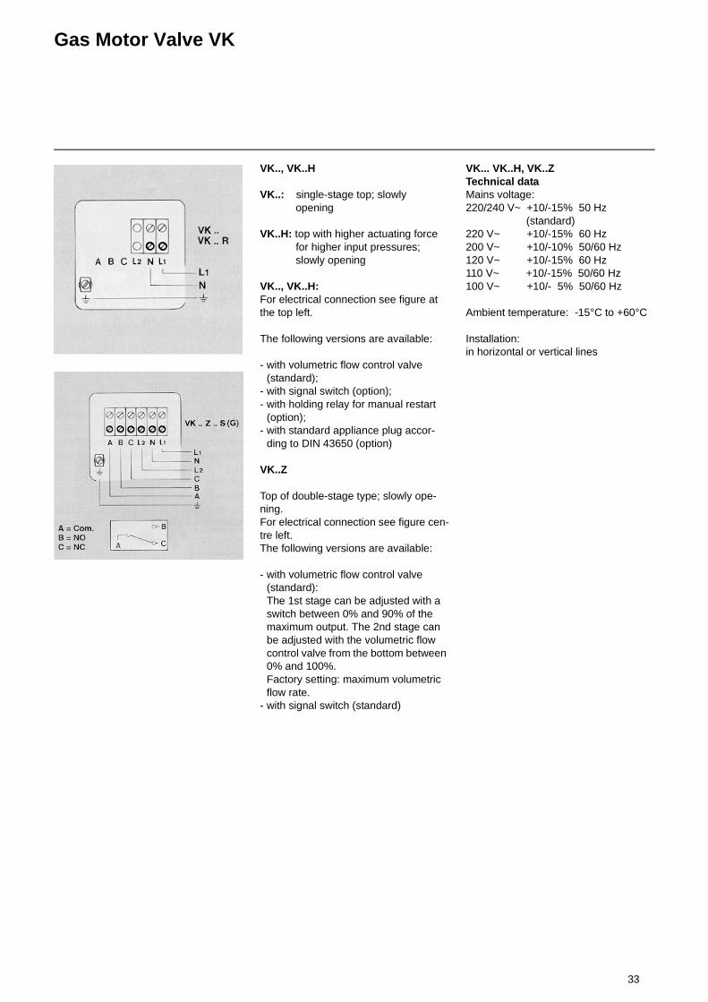
VK.., VK..H
VK..: single-stage top; slowly opening
VK..H: top with higher actuating force for higher input pressures; slowly opening
VK.., VK..H:For electrical connection see figure at the top left.
The following versions are available:
- with volumetric flow control valve (standard);
- with signal switch (option);- with holding relay for manual restart
(option);- with standard appliance plug accor-
ding to DIN 43650 (option)
VK..Z
Top of double-stage type; slowly ope-ning.For electrical connection see figure cen-tre left.The following versions are available:
- with volumetric flow control valve (standard):The 1st stage can be adjusted with a switch between 0% and 90% of the maximum output. The 2nd stage can be adjusted with the volumetric flow control valve from the bottom between 0% and 100%.Factory setting: maximum volumetric flow rate.
- with signal switch (standard)
VK... VK..H, VK..ZTechnical dataMains voltage:220/240 V~ +10/-15% 50 Hz
(standard)220 V~ +10/-15% 60 Hz200 V~ +10/-10% 50/60 Hz120 V~ +10/-15% 60 Hz110 V~ +10/-15% 50/60 Hz100 V~ +10/- 5% 50/60 Hz
Ambient temperature: -15°C to +60°C
Installation:in horizontal or vertical lines

34
Gas Pressure Regulator
Gas pressure regulator with separate safety blow-off valve
Blow-off line R 1"
Safety blow-off valve
Instrument line ∅ 12 mm
appr. 10 x d
Gas pressure regulator with built-in safety blow-off valve
Vent line 1/2"
Instrument line
appr. 10 x d
Blow-off line
Safety blow-off
12 mm outside ∅
valve
35
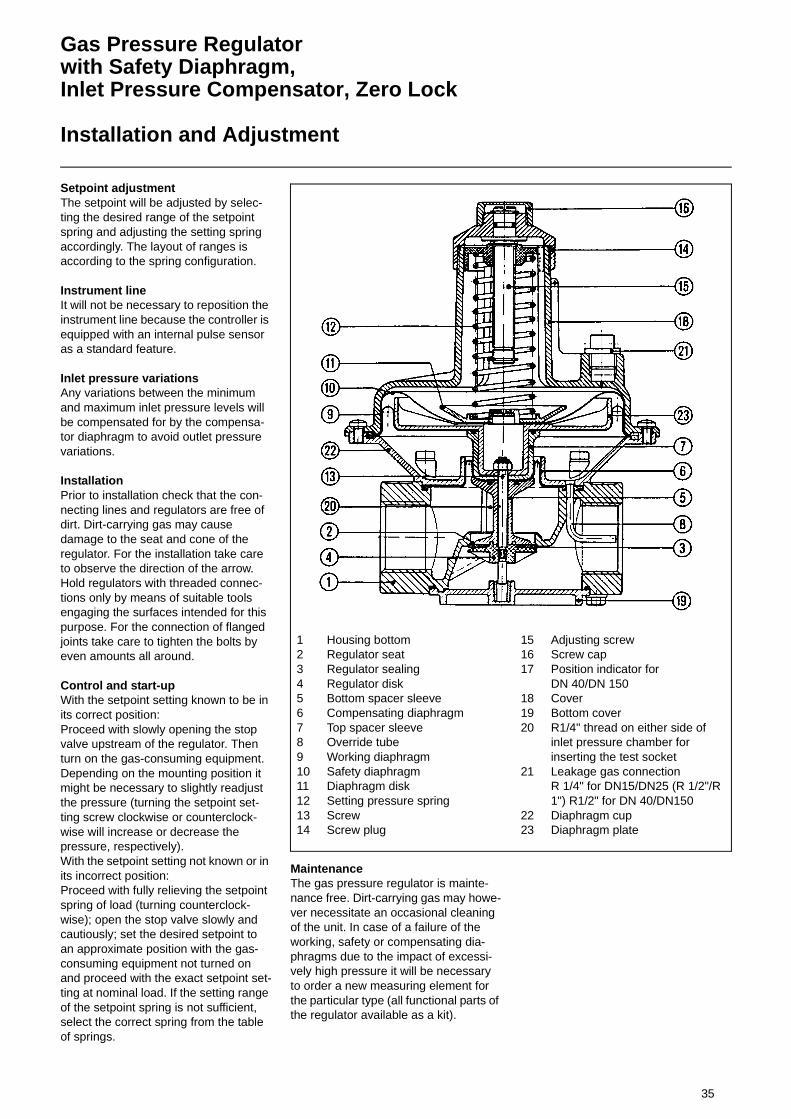
Gas Pressure Regulatorwith Safety Diaphragm,Inlet Pressure Compensator, Zero Lock
Installation and Adjustment
Setpoint adjustmentThe setpoint will be adjusted by selec-ting the desired range of the setpoint spring and adjusting the setting spring accordingly. The layout of ranges is according to the spring configuration.
Instrument lineIt will not be necessary to reposition the instrument line because the controller is equipped with an internal pulse sensor as a standard feature.
Inlet pressure variationsAny variations between the minimum and maximum inlet pressure levels will be compensated for by the compensa-tor diaphragm to avoid outlet pressure variations.
InstallationPrior to installation check that the con-necting lines and regulators are free of dirt. Dirt-carrying gas may cause damage to the seat and cone of the regulator. For the installation take care to observe the direction of the arrow. Hold regulators with threaded connec-tions only by means of suitable tools engaging the surfaces intended for this purpose. For the connection of flanged joints take care to tighten the bolts by even amounts all around.
Control and start-upWith the setpoint setting known to be in its correct position: Proceed with slowly opening the stop valve upstream of the regulator. Then turn on the gas-consuming equipment. Depending on the mounting position it might be necessary to slightly readjust the pressure (turning the setpoint set-ting screw clockwise or counterclock-wise will increase or decrease the pressure, respectively).With the setpoint setting not known or in its incorrect position:Proceed with fully relieving the setpoint spring of load (turning counterclock-wise); open the stop valve slowly and cautiously; set the desired setpoint to an approximate position with the gas-consuming equipment not turned on and proceed with the exact setpoint set-ting at nominal load. If the setting range of the setpoint spring is not sufficient, select the correct spring from the table of springs.
MaintenanceThe gas pressure regulator is mainte-nance free. Dirt-carrying gas may howe-ver necessitate an occasional cleaning of the unit. In case of a failure of the working, safety or compensating dia-phragms due to the impact of excessi-vely high pressure it will be necessary to order a new measuring element for the particular type (all functional parts of the regulator available as a kit).
1 Housing bottom2 Regulator seat3 Regulator sealing4 Regulator disk5 Bottom spacer sleeve6 Compensating diaphragm7 Top spacer sleeve8 Override tube9 Working diaphragm10 Safety diaphragm11 Diaphragm disk12 Setting pressure spring13 Screw14 Screw plug
15 Adjusting screw16 Screw cap17 Position indicator for
DN 40/DN 15018 Cover19 Bottom cover20 R1/4" thread on either side of
inlet pressure chamber for inserting the test socket
21 Leakage gas connection R 1/4" for DN15/DN25 (R 1/2"/R 1") R1/2" for DN 40/DN150
22 Diaphragm cup23 Diaphragm plate
36
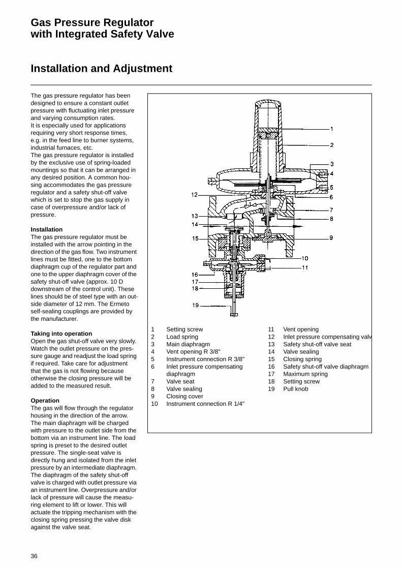
Gas Pressure Regulatorwith Integrated Safety Valve
Installation and Adjustment
The gas pressure regulator has been designed to ensure a constant outlet pressure with fluctuating inlet pressure and varying consumption rates.It is especially used for applications requiring very short response times, e.g. in the feed line to burner systems, industrial furnaces, etc.The gas pressure regulator is installed by the exclusive use of spring-loaded mountings so that it can be arranged in any desired position. A common hou-sing accommodates the gas pressure regulator and a safety shut-off valve which is set to stop the gas supply in case of overpressure and/or lack of pressure.
InstallationThe gas pressure regulator must be installed with the arrow pointing in the direction of the gas flow. Two instrument lines must be fitted, one to the bottom diaphragm cup of the regulator part and one to the upper diaphragm cover of the safety shut-off valve (approx. 10 D downstream of the control unit). These lines should be of steel type with an out-side diameter of 12 mm. The Ermeto self-sealing couplings are provided by the manufacturer.
Taking into operationOpen the gas shut-off valve very slowly. Watch the outlet pressure on the pres-sure gauge and readjust the load spring if required. Take care for adjustment that the gas is not flowing because otherwise the closing pressure will be added to the measured result.
OperationThe gas will flow through the regulator housing in the direction of the arrow. The main diaphragm will be charged with pressure to the outlet side from the bottom via an instrument line. The load spring is preset to the desired outlet pressure. The single-seat valve is directly hung and isolated from the inlet pressure by an intermediate diaphragm. The diaphragm of the safety shut-off valve is charged with outlet pressure via an instrument line. Overpressure and/or lack of pressure will cause the measu-ring element to lift or lower. This will actuate the tripping mechanism with the closing spring pressing the valve disk against the valve seat.
1 Setting screw2 Load spring3 Main diaphragm4 Vent opening R 3/8"5 Instrument connection R 3/8"6 Inlet pressure compensating
diaphragm7 Valve seat8 Valve sealing9 Closing cover10 Instrument connection R 1/4"
11 Vent opening12 Inlet pressure compensating valv13 Safety shut-off valve seat14 Valve sealing15 Closing spring16 Safety shut-off valve diaphragm17 Maximum spring18 Setting screw19 Pull knob
37
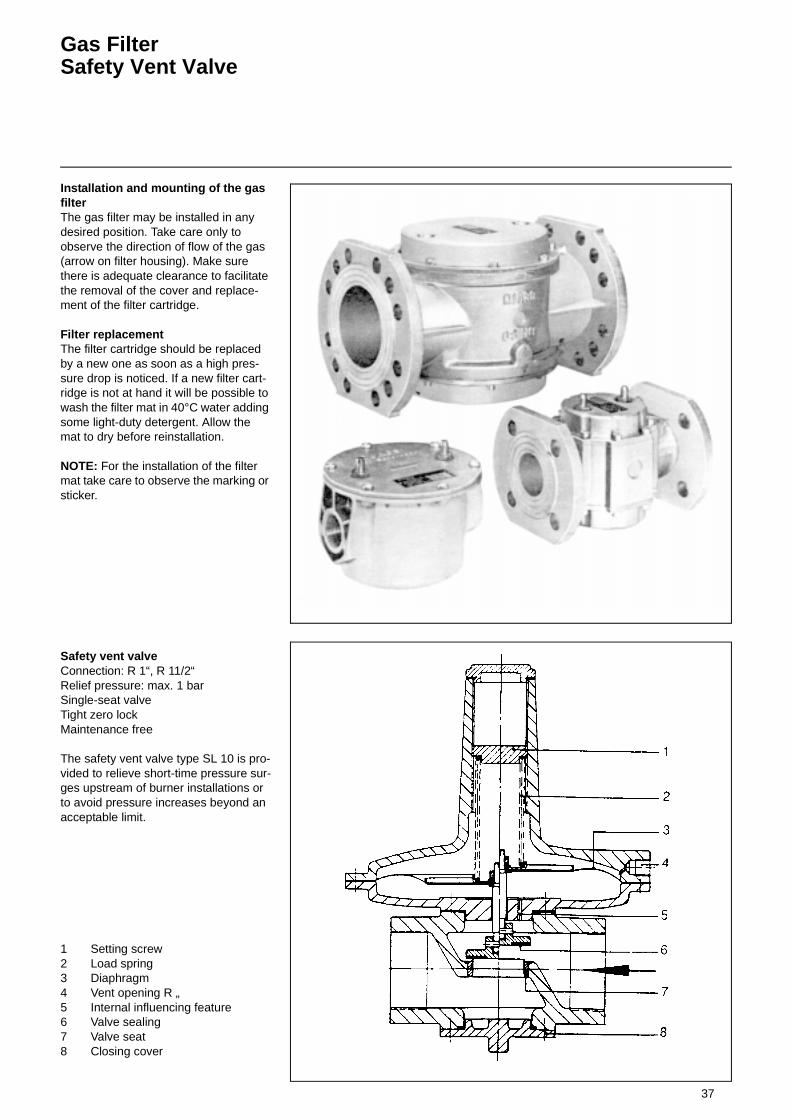
Gas FilterSafety Vent Valve
Installation and mounting of the gas filterThe gas filter may be installed in any desired position. Take care only to observe the direction of flow of the gas (arrow on filter housing). Make sure there is adequate clearance to facilitate the removal of the cover and replace-ment of the filter cartridge.
Filter replacementThe filter cartridge should be replaced by a new one as soon as a high pres-sure drop is noticed. If a new filter cart-ridge is not at hand it will be possible to wash the filter mat in 40°C water adding some light-duty detergent. Allow the mat to dry before reinstallation.
NOTE: For the installation of the filter mat take care to observe the marking or sticker.
Safety vent valveConnection: R 1“, R 11/2“Relief pressure: max. 1 barSingle-seat valveTight zero lockMaintenance free
The safety vent valve type SL 10 is pro-vided to relieve short-time pressure sur-ges upstream of burner installations or to avoid pressure increases beyond an acceptable limit.
1 Setting screw2 Load spring3 Diaphragm4 Vent opening R „5 Internal influencing feature6 Valve sealing7 Valve seat8 Closing cover
38
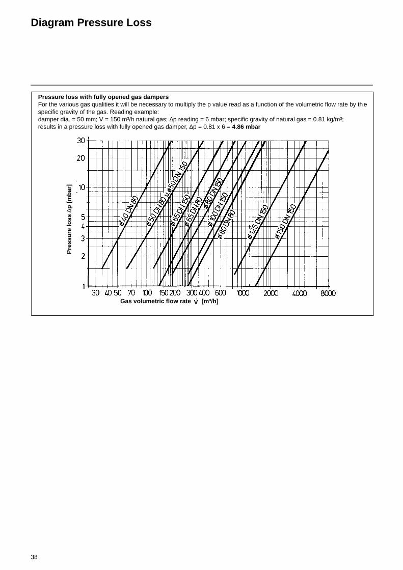
Diagram Pressure Loss
Pressure loss with fully opened gas dampersFor the various gas qualities it will be necessary to multiply the p value read as a function of the volumetric flow rate by th e specific gravity of the gas. Reading example: damper dia. = 50 mm; V = 150 m³/h natural gas; ∆p reading = 6 mbar; specific gravity of natural gas = 0.81 kg/m³; results in a pressure loss with fully opened gas damper, ∆p = 0.81 x 6 = 4.86 mbar
Gas volumetric flow rate [m³/h]V·
Pre
ssu
re lo
ss ∆
p [
mb
ar]

39
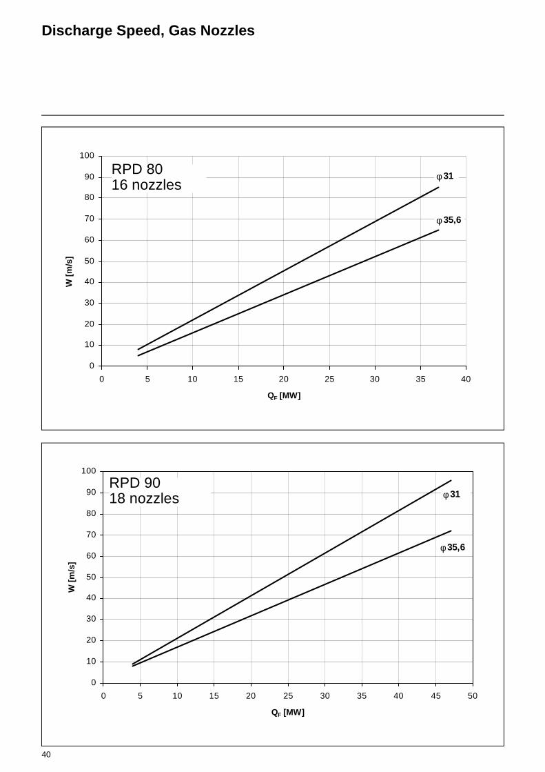
Discharge Speed, Gas Nozzles
0
10
20
30
40
50
60
70
80
90
100
110
120
0 1 2 3 4 5 6 7 8 9 10QF [MW]
W [
m/s
]
φ18
φ22
φ26
RPD 30 u. 408 nozzles
0
10
20
30
40
50
60
70
80
90
100
110
120
130
140
150
0 2 4 6 8 10 12 14 16 18 20 22
QF [MW]
W [
m/s
]
φ18
φ22
φ26
φ35,6
φ31
RPD 50, 60 u. 7012 nozzles
40
Discharge Speed, Gas Nozzles
0
10
20
30
40
50
60
70
80
90
100
0 5 10 15 20 25 30 35 40
QF [MW]
W [
m/s
]
φ 31
φ 35,6
RPD 8016 nozzles
0
10
20
30
40
50
60
70
80
90
100
0 5 10 15 20 25 30 35 40 45 50
QF [MW]
W [
m/s
]
φ 31
φ 35,6
RPD 9018 nozzles
41
Preoperational ChecksFunctional Test without FuelGas Start-up
Checks prior to operationCheck the following prior to the initial operation of the boiler system:
• Take care to observe the operating instructions supplied by the boiler manufacturer.
• Check the boiler system for correct electrical wiring of all parts including the valves and instruments.
• Check the air fan motor for correct direction of rotation.
• Check for the proper setting of the temperature and pressure controllers, limiters and safety switches.
• Check for adequate fuel supply and sufficiently high gas connection pres-sure.
• Make a leak test of the fuel-carrying lines (ensure they are free of air).
• Ensure that the exhaust gas ports are open and fresh air is taken in at the required rate.
• Make sure the burner is in starting position.
• Check that automatic furnace control-ler is unlocked.
A pressure test should be made of the gas valves and instruments group using air or nitrogen at the 1.1-fold operating pressure but at least 60 mbar above the operating pressure. Joints like flanges, screwed unions, etc. must be sprayed with foaming agents and checked for absence of leaks. Take care to observe the maximum operating pressure of the valves and instruments. After the tem-perature has been allowed to equalize make sure the test pressure does not drop for a subsequent test period of 10 minutes.
Gas line ventingThe gas line and valves/instruments must be vented before taking the burner into operation. Use a test burner for detecting any residual gas in the system.
Functional test without fuelCheck the burner for proper functional order without using a fuel. In gas opera-ting mode close the gas stop valve.
Start-upFor taking the duoblock burner type RPD into operation, it will be required to carefully adjust the burner system by duly following the adjusting instructions and procedures. After the burner and boiler have been tested in the way des-cribed above, the burner may be taken into operation.
Gas start-up• Set the emergency and main switches
to their „ON“ positions.• Open the ball stop valve upstream of
the gas valve and check the gas pres-sure on the pressure gauge mounted upstream of the gas pressure control-ler.
• Set the fuel selector switch to its „Gas“ position.
• Set the control switch to its position „1“.
• Set the load selector switch to its posi-tion „0“ = Partial Load or „1“ = Regula-ting Load, as required. For adjusting the burner make sure the switch is in its „Regulating Load“ position.
• Set the service switch also to its posi-tion „1“.
• The „Manual-Automatic“ selector switch is in its „Automatic“ position during start-up and operation.
• When adjusting the burner be sure the switch is changed over to its „Manual“ position.
• Unlock the automatic furnace control-ler.If a leak test is made with the val-ves the automatic furnace controller should not be unlocked until the leak test has been successfully completed. The burner will start according to the program flow preset by the automatic furnace controller. The burner will now be in operation. In case a leak is detected with the valves the program will not proceed to the automatic fur-nace controller.
42
Burner ShutdownMeasures in Case of Trouble
Burner shutdown
1. Set the control switch to position „0“.
2. Set the fuel selector switch to position „0“.
3. Close the gas stop valve.4. For short periods of shutdown the
fuel stop valves may remain in their open positions.
5. For longer periods of shutdown and for inspections make sure to set all switches to their „OFF“ positions and close the gas stop valve.
6. Have the furnace system inspec-ted at least once a year by the local service company to ensure its efficient operation and com-pliance with the applicable air pol-lution control regulations.
7. Any conditions deviating from standards and any faults should immediately be reported to the installer of the system and elimi-nated without delay.
Measures in case of troubleAny trouble of the burner will be indica-ted by the illuminated pushbutton switch (red light) in the control cabinet or auto-matic furnace controller. If the trouble can be eliminated the automatic furnace controller can be unlocked by pressing any of the two illuminated pushbutton switches causing the burner to restart in accordance with the program. If the bur-ner returns to its trouble position the local service personnel should be called to site. In case of a negative result of the valve leak test make sure to close the gas stop valve at once and call the service personnel to site.
Regular checks and maintenance measures• Check the gas pressure on the pres-
sure gauge.• Check the safety time of the automatic
furnace controller by pulling out the UV flame monitor.
• The safety time must be 2 seconds for start-up while during normal operation the burner must be shut down without delay.
• Clean the UV tube if dirt has accumu-lated.
• Clean all filters at regular intervals and check for absence of leaks. Wash the filter mat of gas filters with water (max. 40°C) adding a commercial light-duty detergent if required. Do not hose down the filters with a high-pressure water jet. Dry the filter mat and rein-stall in filter housing. When reinstalling the filter cartridge take care that it is located by the filter housing groove and the filter cover.

43
Exhaust Gas Test
Exhaust gas testTo ensure an economically efficient and trouble-free operation of the system it will be necessary to adjust the burner specifically in accordance with the furnace system. This is achieved by means of a fuel-combustion air compound control unit which adjusts the burner to ensure a proper combustion. Exhaust gas tests are required for this purpose. The percentage CO2 and O2 and the exhaust gas temperature will have to be measured to determine the efficiency and combustion quality.Prior to any measurement make sure to check the boiler and exhaust gas system for absence of leaks.
Secondary air will falsify the measured resultsCheck that the exhaust gases have a residual oxy-gen (O2) content as low as possible and a carbon dioxide (CO2) content as high as possible.The carbon monoxide content of the exhaust gases must be below the currently applicable specificati-ons in all load stages.In the fuel oil combustion mode the permissible soot number in the exhaust gas is not allowed to be exceeded.
Determining the volumetric gas flow rateThe thermal furnace output of a boiler (QF) is the amount of heat supplied with the gas in a unit of time.When taking the burner into operation the volumetric fuel flow rate should be selected according to the nominal ther-mal capacity of the boiler. Example:
Mean barometer readings
Nom. thermal output QN 1000 kWBoiler efficiency nK 0,88Calorific value of gas Hu 9,1 kWh/m³Gas pressure pu 100 mbarBarometer reading pamb 980 mbarGas temperature tgas 15 °CStandard pressure pn 1013 mbar
Sealevel
[m]
Mean barometerreadings[mbar]
Aachen 205 991Berlin 50 1009Dresden 120 1000Erfurt 315 978Frankfurt/M. 104 1004Hamburg 22 1011Cologne 45 1009Leipzig 130 998Magdeburg 79 1005Munich 526 955Nuremberg 310 980Rostock 4 1013Stuttgart 297 984Schwerin 59 1010Ulm 479 960
Volumetric gas flow rate at STP:
Volumetric gas flow rate in operating condition:
Ratio between O2- and CO2- for natu-ral gas H (CO2max =11,86%)
%O2 %CO2 %O2 %CO2
0,00 11,86 3,00 10,160,10 11,80 3,10 10,100,20 11,75 3,20 10,040,30 11,69 3,30 9,990,40 11,63 3,40 9,930,50 11,58 3,50 9,870,60 11,52 3,60 9,820,70 11,46 3,70 9,760,80 11,41 3,80 9,700,90 11,35 3,90 9,651,00 11,29 4,00 9,591,10 11,24 4,10 9,531,20 11,18 4,20 9,481,30 11,12 4,30 9,421,40 11,07 4,40 9,361,50 11,01 4,50 9,311,60 10,95 4,60 9,251,70 10,90 4,70 9,191,80 10,84 4,80 9,141,90 10,78 4,90 9,082,00 10,73 5,00 9,022,10 10,67 5,10 8,972,20 10,61 5,20 8,912,30 10,55 5,30 8,852,40 10,50 5,40 8,802,50 10,44 5,50 8,742,60 10,38 5,60 8,682,70 10,33 5,70 8,632,80 10,27 5,80 8,572,90 10,21 5,90 8,51
O2 21CO2max CO2gem–
CO2max-----------------------------------------------× %==
600
700
800
900
1000
0 1000 2000 3000 4000 5000
Höhe in m.ü.M.
Mit
tler
er L
uft
dru
ck in
mb
ar
450
960
1013,25
Altitude in m above sea level
Mea
n at
mos
pher
ic p
ress
ure
in m
bar

44
O2, CO2, Lambda Conversion Table
Natural Gas
Relation between O2 and CO2 value for natural gas (CO2max=11,8 %)
%O2 %CO2 Air index
0,00 11,80 1,000,10 11,74 1,000,20 11,69 1,01
0,30 11,63 1,010,40 11,58 1,020,50 11,52 1,02
0,60 11,46 1,030,70 11,41 1,030,80 11,35 1,04
0,90 11,29 1,04
1,00 11,24 1,05
1,10 11,18 1,061,20 11,13 1,061,30 11,07 1,07
1,40 11,01 1,071,50 10,96 1,081,60 10,90 1,08
1,70 10,84 1,091,80 10,79 1,091,90 10,73 1,10
2,00 10,68 1,112,10 10,62 1,11
2,20 10,56 1,122,30 10,51 1,122,40 10,45 1,13
2,50 10,40 1,142,60 10,34 1,142,70 10,28 1,15
2,80 10,23 1,152,90 10,17 1,16
3,00 10,11 1,173,10 10,06 1,173,20 10,00 1,18
3,30 9,95 1,193,40 9,89 1,193,50 9,83 1,20
3,60 9,78 1,213,70 9,72 1,213,80 9,66 1,22
3,90 9,61 1,23
O2 21CO2max CO2gem–
CO2max-----------------------------------------------× %==
%O2 %CO2 Air index
4,00 9,55 1,244,10 9,50 1,244,20 9,44 1,25
4,30 9,38 1,264,40 9,33 1,274,50 9,27 1,27
4,60 9,22 1,284,70 9,16 1,294,80 9,10 1,30
4,90 9,05 1,30
5,00 8,99 1,31
5,10 8,93 1,325,20 8,88 1,335,30 8,82 1,34
5,40 8,77 1,355,50 8,71 1,355,60 8,65 1,36
5,70 8,60 1,375,80 8,54 1,385,90 8,48 1,39
6,00 8,43 1,406,10 8,37 1,41
6,20 8,32 1,426,30 8,26 1,436,40 8,20 1,44
6,50 8,15 1,456,60 8,09 1,46
6,70 8,04 1,476,80 7,98 1,486,90 7,92 1,49
7,00 7,87 1,507,10 7,81 1,51
7,20 7,75 1,527,30 7,70 1,537,40 7,64 1,54
7,50 7,59 1,567,60 7,53 1,577,70 7,47 1,58
7,80 7,42 1,597,90 7,36 1,60
%O2 %CO2 Air index
8,00 7,30 1,628,10 7,25 1,638,20 7,19 1,64
8,30 7,14 1,658,40 7,08 1,678,50 7,02 1,68
8,60 6,97 1,698,70 6,91 1,718,80 6,86 1,72
8,90 6,80 1,74
9,00 6,74 1,75
9,10 6,69 1,769,20 6,63 1,789,30 6,57 1,79
9,40 6,52 1,819,50 6,46 1,839,60 6,41 1,84
9,70 6,35 1,869,80 6,29 1,879,90 6,24 1,89
10,00 6,18 1,9110,10 6,12 1,93
10,20 6,07 1,9410,30 6,01 1,9610,40 5,96 1,98
10,50 5,90 2,0010,60 5,84 2,02
10,70 5,79 2,0410,80 5,73 2,0610,90 5,68 2,08
11,00 5,62 2,1011,10 5,56 2,12
11,20 5,51 2,1411,30 5,45 2,1611,40 5,39 2,19
11,50 5,34 2,2111,60 5,28 2,2311,70 5,23 2,26
11,80 5,17 2,2811,90 5,11 2,31
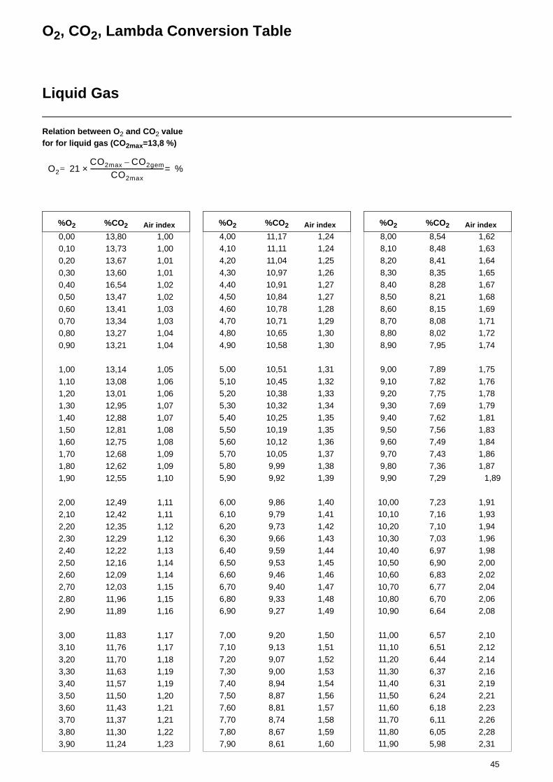
45
O2, CO2, Lambda Conversion Table
Liquid Gas
Relation between O2 and CO2 value for for liquid gas (CO2max=13,8 %)
%O2 %CO2 Air index
0,00 13,80 1,000,10 13,73 1,000,20 13,67 1,01
0,30 13,60 1,010,40 16,54 1,020,50 13,47 1,02
0,60 13,41 1,030,70 13,34 1,030,80 13,27 1,04
0,90 13,21 1,04
1,00 13,14 1,05
1,10 13,08 1,061,20 13,01 1,061,30 12,95 1,07
1,40 12,88 1,071,50 12,81 1,081,60 12,75 1,08
1,70 12,68 1,091,80 12,62 1,091,90 12,55 1,10
2,00 12,49 1,112,10 12,42 1,11
2,20 12,35 1,122,30 12,29 1,122,40 12,22 1,13
2,50 12,16 1,142,60 12,09 1,142,70 12,03 1,15
2,80 11,96 1,152,90 11,89 1,16
3,00 11,83 1,173,10 11,76 1,17
3,20 11,70 1,183,30 11,63 1,193,40 11,57 1,19
3,50 11,50 1,203,60 11,43 1,213,70 11,37 1,21
3,80 11,30 1,223,90 11,24 1,23
O2 21CO2max CO2gem–
CO2max-----------------------------------------------× %==
%O2 %CO2 Air index
4,00 11,17 1,244,10 11,11 1,244,20 11,04 1,25
4,30 10,97 1,264,40 10,91 1,274,50 10,84 1,27
4,60 10,78 1,284,70 10,71 1,294,80 10,65 1,30
4,90 10,58 1,30
5,00 10,51 1,31
5,10 10,45 1,325,20 10,38 1,335,30 10,32 1,34
5,40 10,25 1,355,50 10,19 1,355,60 10,12 1,36
5,70 10,05 1,375,80 9,99 1,385,90 9,92 1,39
6,00 9,86 1,406,10 9,79 1,41
6,20 9,73 1,426,30 9,66 1,436,40 9,59 1,44
6,50 9,53 1,456,60 9,46 1,46
6,70 9,40 1,476,80 9,33 1,486,90 9,27 1,49
7,00 9,20 1,507,10 9,13 1,51
7,20 9,07 1,527,30 9,00 1,537,40 8,94 1,54
7,50 8,87 1,567,60 8,81 1,577,70 8,74 1,58
7,80 8,67 1,597,90 8,61 1,60
%O2 %CO2 Air index
8,00 8,54 1,628,10 8,48 1,638,20 8,41 1,64
8,30 8,35 1,658,40 8,28 1,678,50 8,21 1,68
8,60 8,15 1,698,70 8,08 1,718,80 8,02 1,72
8,90 7,95 1,74
9,00 7,89 1,75
9,10 7,82 1,769,20 7,75 1,789,30 7,69 1,79
9,40 7,62 1,819,50 7,56 1,839,60 7,49 1,84
9,70 7,43 1,869,80 7,36 1,879,90 7,29 1,89
10,00 7,23 1,9110,10 7,16 1,93
10,20 7,10 1,9410,30 7,03 1,9610,40 6,97 1,98
10,50 6,90 2,0010,60 6,83 2,02
10,70 6,77 2,0410,80 6,70 2,0610,90 6,64 2,08
11,00 6,57 2,1011,10 6,51 2,12
11,20 6,44 2,1411,30 6,37 2,1611,40 6,31 2,19
11,50 6,24 2,2111,60 6,18 2,2311,70 6,11 2,26
11,80 6,05 2,2811,90 5,98 2,31
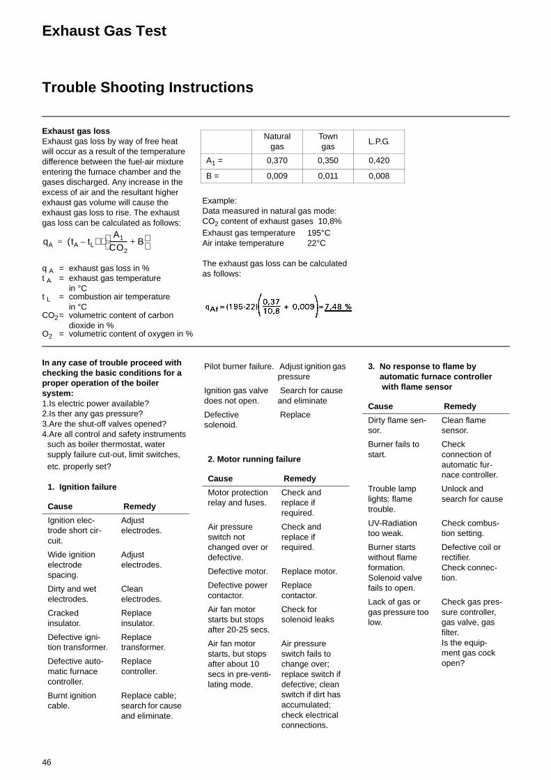
46
Exhaust Gas Test
Trouble Shooting Instructions
Exhaust gas lossExhaust gas loss by way of free heat will occur as a result of the temperature difference between the fuel-air mixture entering the furnace chamber and the gases discharged. Any increase in the excess of air and the resultant higher exhaust gas volume will cause the exhaust gas loss to rise. The exhaust gas loss can be calculated as follows:
Example:Data measured in natural gas mode:CO2 content of exhaust gases 10,8%Exhaust gas temperature 195°CAir intake temperature 22°C
The exhaust gas loss can be calculated as follows:
q A = exhaust gas loss in %t A = exhaust gas temperature
in °Ct L = combustion air temperature
in °CCO2= volumetric content of carbon
dioxide in %O2 = volumetric content of oxygen in %
qA tA tL–( )A1
CO2----------- B+
⋅=
Naturalgas
Towngas
L.P.G.
A1 = 0,370 0,350 0,420
B = 0,009 0,011 0,008
In any case of trouble proceed with checking the basic conditions for a proper operation of the boiler system:1.Is electric power available?2.Is ther any gas pressure?3.Are the shut-off valves opened?4.Are all control and safety instruments
such as boiler thermostat, water supply failure cut-out, limit switches, etc. properly set?
1. Ignition failure
Cause Remedy
Ignition elec-trode short cir-cuit.
Adjust electrodes.
Wide ignition electrode spacing.
Adjust electrodes.
Dirty and wet electrodes.
Clean electrodes.
Cracked insulator.
Replace insulator.
Defective igni-tion transformer.
Replace transformer.
Defective auto-matic furnace controller.
Replace controller.
Burnt ignition cable.
Replace cable; search for cause and eliminate.
Pilot burner failure. Adjust ignition gas pressure
Ignition gas valve does not open.
Search for cause and eliminate
Defective solenoid.
Replace
2. Motor running failure
Cause Remedy
Motor protection relay and fuses.
Check and replace if required.
Air pressure switch not changed over or defective.
Check and replace if required.
Defective motor. Replace motor.
Defective power contactor.
Replace contactor.
Air fan motor starts but stops after 20-25 secs.
Check for solenoid leaks
Air fan motor starts, but stops after about 10 secs in pre-venti-lating mode.
Air pressure switch fails to change over; replace switch if defective; clean switch if dirt has accumulated; check electrical connections.
3. No response to flame by automatic furnace controller with flame sensor
Cause Remedy
Dirty flame sen-sor.
Clean flame sensor.
Burner fails to start.
Check connection of automatic fur-nace controller.
Trouble lamp lights; flame trouble.
Unlock and search for cause
UV-Radiation too weak.
Check combus-tion setting.
Burner starts without flame formation. Solenoid valve fails to open.
Defective coil or rectifier. Check connec-tion.
Lack of gas or gas pressure too low.
Check gas pres-sure controller, gas valve, gas filter. Is the equip-ment gas cock open?
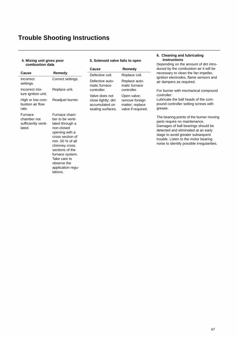
47
Trouble Shooting Instructions
6. Cleaning and lubricating instructionsDepending on the amount of dirt intro-duced by the combustion air it will be necessary to clean the fan impeller, ignition electrodes, flame sensors and air dampers as required.
For burner with mechanical compound controller:Lubricate the ball heads of the com-pound controller setting screws with grease.
The bearing points of the burner moving parts require no maintenance.Damages of ball bearings should be detected and eliminated at an early stage to avoid greater subsequent trouble. Listen to the motor bearing noise to identify possible irregularities.
4. Mixing unit gives poor combustion data
Cause Remedy
Incorrect settings.
Correct settings.
Incorrect mix-ture ignition unit.
Replace unit.
High or low com-bustion air flow rate.
Readjust burner.
Furnace chamber not sufficiently venti-lated.
Furnace cham-ber to be venti-lated through a non-closed opening with a cross section of min. 50 % of all chimney cross sections of the furnace system. Take care to observe the application regu-lations.
5. Solenoid valve fails to open
Cause Remedy
Defective coil. Replace coil.
Defective auto-matic furnace controller.
Replace auto-matic furnace controller.
Valve does not close tightly; dirt accumulated on sealing surfaces.
Open valve; remove foreign matter; replace valve if required.

97
Customer Service:
ECB GmbHStruppener Strasse01796 Pirna