operation manual ar-727-cm http server
TRANSCRIPT

System Requirements
SOYAL Website Software Download
Web Browser Setting Interface
Cross-Platform Services does not limit to particular operating system, smartphone, or tablet
Setting Fire Alarm Auto Release Doors and TCP/IP Remote I/O Control Setting
SOYAL Operation ManualV211013
AR-727-CMHTTP Server
Operation Manual

01
Table of Contents
References
HTTP ServerIntroduction
1-1 Main Features ......................................................
2-2 Architecture Schematic Diagrams ........................
Interface Overview
Interface Overview
2-1 Log in HTTP Server page ......................................
2-2 Device Connection Status ....................................
2-3 Network Setting ............................................
2-4 RS485 Parameter Setting .....................................
2-5 I/O Direct Control and Query .................................
3-1 TCP/IP Converter Setting .....................................
3-2 Fire Alarm Auto Release Doors ............................. 3-2-1 Fire Alarm Auto Release Doors (RS485 method) 3-2-2 Fire Alarm Auto Release Doors (UDP method) 3-2-3 Fire Alarm Auto Release Lift Door 3-2-4 Fire Alarm Indicator
3-3 TCP/IP Remote I/O Control Setting.......................
3-4 Server-Client Mode Communication Bridge..........
3-5 Change Login Password.......................................
4-1 FAQ .....................................................................
4-2 YouTube Videos....................................................
4-3 Firmware...............................................................
SOYAL TECHNOLOGY CO., LTD
SOYAL Operation Manual
AR-727-CM HTTP Server
1
4
2
3
02
03
04
05
07
10
11
16
17
19
01
02
19
20
20

1. HTTP Server Introduction
1-1 Main Features
Easy setup via Smartphone, Tablet, and PC by entering IP address of the devices through web browser
HTTP Server is compatible for SOYAL Enterprise Series (listed on separate manual refer to ‘Operation Manual Enterprise Series HTTP Server’), SOYAL Industry Series (TCP), AR-716-E18 Ethernet module AR-727i-V3 and Converter AR-727-CM.
HTTP Server Comparison Table
Devices with DI/DO onboard, through HTTP Server could directly control and monitor recent status of onboard DI/DO
Connect to Fire Detector Central Control when fire alarm occurred, automatically notified designated controller to open door
Establish a Server-Client connection bridge to extend wiring, limitless wiring distance, or to provide wireless connection.
AR-727-CM-IO-0804M through its DI/DO features provides TCP to Wiegand signal conversion, at the same time all of Industrial Series built-in Modbus communication protocol that could easily works with third party integration of Monitoring Software and SCADA.
Interface Menu Enterprise Series
Industry Series (TCP)AR-727-CM-0804M
AR-401-IO-0808R-U2
AR-727i-V3(AR-716-E18
Ethernet module)
ConverterAR-727-CM
1 Current State V V V V2 Network Setting V V V V
3
Controller Setting:Event Log /User List / Controller Parameter /User Add/Change / Timezone / Clock
V
4 Login Password V V V V
5RS485 Setting:Channel 1 Setting / Channel 2 Setting
V V
6I/O Control Setting:Direct Control IO 0~3 / Direct Control IO 4~7
V
1. HTTP Server Introduction
SOYAL TECHNOLOGY CO., LTD
SOYAL Operation Manual
AR-727-CM HTTP Server
01

1
2
ID:SuperAdmPWD:721568
3
Remote setting by computer, Pad, Smartphone
Fire Alarm Output (Dry Contact)
Modem
Power
Multi Functional Access ControllerAR-721-H
Fire DetectorCentral Control
2-1
2. Interface Overview
Log in HTTP Server page
1 Through PC, Tablet, or Smartphone web browser software/app, enter device IP Address and enter HTTP Server interface (default IP Address 192.168.1.127)
AR-727-CM-IO- 0804MEHR0527600513.57.043A7B
2. Interface Overview
+
SOYAL TECHNOLOGY CO., LTD
SOYAL Operation Manual
AR-727-CM HTTP Server
02

1
2
2
1
2
3
When entering HTTP Server page required entering ID and Password. Default ID: SuperAdm / Password: 721568 which can also be found on serial no. sticker that include on the packaging.(For older version, default ID: admin / password: admin)
Device Model no. and Firmware VersionAfter logged in, on the top right side will show the controller’s model no. including the firmware version
After logged in, the first menu that will automatically show Current State that will indicate connection status
Connection Status can be seen between devices to HTTP Server (Port 80) and device to 701Server (Port 1621 for Enterprise Series Controller or via AR-727-CM CH1 / Port 1623 if via AR-727CM CH2)
2-2 Device Connection Status
2. Interface Overview
From the example above:
1. 192.168.001.078:(0080) CONNECTED -> indicated device with IP address 192.168.1.78
has connected to HTTP Server
2. 192.168.001.002:(1621) CONNECTED -> indicated device with IP address 192.168.1.2
has connected to 701Server
Note :
SOYAL TECHNOLOGY CO., LTD
SOYAL Operation Manual
AR-727-CM HTTP Server
03

1
234567891011
12
2-3 Network Setting
ID:SuperAdmPWD:721568
AR-727-CM-IO- 0804MEHR0527600513.57.043A7B
Productserial number
MAC Address
12
3
4
5
6
7
8
Click the ‘Network Setting’ on the left side menuDevice Name: Rename network device, could be used to differentiate between one device and anotherLAN IP Address: Enter IP address designated for the device of the intranet.Default setting is 192.168.1.127LAN Net Mask: Subnet Mask of the intranetDefault Gateway: Default gateway of the intranet. if there is Internet connection access, this IP address must point to the router or the gateway provided by the ISPPrimary DNS Server: Domain Name Server 1Secondary DNS Server: Domain Name Server 2MAC Address:Network physical address (this field cannot be changed).Each TCP/IP device has designated MAC address that could be found on the serial number sticker
SOYAL TECHNOLOGY CO., LTD
SOYAL Operation Manual
AR-727-CM HTTP Server
04

12
34
5678
910
1112
1314
15
17
16
2-4 RS485 Parameter Setting
9 HTTP Server Port: 80Web browser service port, it can be change if there is information security consideration but should not have the same TCP Port with 701Server connection to devices which is 1621 or 1623For Example: changing into 9680, to enter the HTTP Server you need to enter IP address followed with Port
*the designated Port should be remembered all time, if not necessary to change the Port, please let it remain default which is 80.
TCP/IP Control Port:Setting of I/O Control Port.Enter 1601 when using 727APP or mobile app connectionEnter 502 for Modbus communication protocol applicationDHCP Client: Ticking this feature will enable dynamic host protocol which means devices will automatically obtain IP address without manually typing and assigned device to a designated IP address.Update: Press Update button to save changed.When you changed the LAN IP Address, after entering Update button, on the browser field required to type new IP address.
10
11
12
SOYAL TECHNOLOGY CO., LTD
SOYAL Operation Manual
AR-727-CM HTTP Server
05
12
34
56
7
8
910
11
12
13
14
15
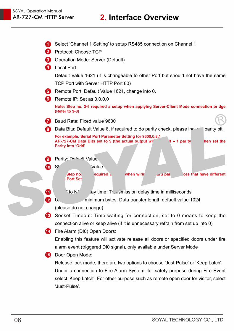
Select ‘Channel 1 Setting’ to setup RS485 connection on Channel 1Protocol: Choose TCPOperation Mode: Server (Default)Local Port: Default Value 1621 (it is changeable to other Port but should not have the same TCP Port with Server HTTP Port 80)Remote Port: Default Value 1621, change into 0.Remote IP: Set as 0.0.0.0Note: Step no. 3-6 required a setup when applying Server-Client Mode connection bridge (Refer to 3-3)
Baud Rate: Fixed value 9600Data Bits: Default Value 8, if required to do parity check, please include parity bit.For example: Serial Port Parameter Setting for 9600,0,8,1AR-727-CM Data Bits set to 9 (the actual output will be 8 bit + 1 parity = 9), then set the Parity into ‘Odd’
Parity: Default Value NoneStop Bits:Default Value 1Note: Step no. 7-10 required a setup when wiring to third party devices that have different Serial Port Setting.
UART to NET delay time: Transmission delay time in millisecondsUART to NET minimum bytes: Data transfer length default value 1024(please do not change)Socket Timeout: Time waiting for connection, set to 0 means to keep the connection alive or keep alive (if it is unnecessary refrain from set up into 0)Fire Alarm (DI0) Open Doors:Enabling this feature will activate release all doors or specified doors under fire alarm event (triggered DI0 signal), only available under Server ModeDoor Open Mode:Release lock mode, there are two options to choose 'Just-Pulse' or 'Keep Latch'.Under a connection to Fire Alarm System, for safety purpose during Fire Event select ‘Keep Latch’. For other purpose such as remote open door for visitor, select ‘Just-Pulse’.
2. Interface Overview
SOYAL TECHNOLOGY CO., LTD
SOYAL Operation Manual
AR-727-CM HTTP Server
06
1
2
Selected Node ID:Select broadcast or specified group of doors to release lock under Fire Event (each RS485 Channel could specified up to 8 doors).Note: Step no.14-16 required a setup when applying Fire Alarm Auto Release Doors (Refer to 3-2)
Update:Press Update button to save changed.
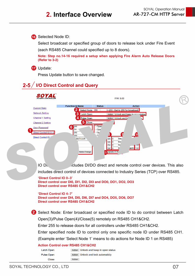
IO Direct Control includes DI/DO direct and remote control over devices. This also includes direct control of devices connected to Industry Series (TCP) over RS485.‘Direct Control IO 0~3’ Direct control over DI0, DI1, DI2, DI3 and DO0, DO1, DO2, DO3Direct control over RS485 CH1&CH2
‘Direct Control IO 4~7’Direct control over DI4, DI5, DI6, DI7 and DO4, DO5, DO6, DO7Direct control over RS485 CH1&CH2
Select Node: Enter broadcast or specified node ID to do control between Latch Open(3)/Pulse Open(4)/Close(5) remotely on RS485 CH1&CH2.Enter 255 to release doors for all controllers under RS485 CH1&CH2.Enter specified node ID to control only one specific node ID under RS485 CH1. (Example enter ‘Select Node 1’ means to do actions for Node ID 1 on RS485)Action Control over RS485 CH1&CH2
16
17
2-5 I/O Direct Control and Query
1
234
56 7
8 9
11
10
2. Interface Overview
SOYAL TECHNOLOGY CO., LTD
SOYAL Operation Manual
AR-727-CM HTTP Server
07
3
6
4
5
7
8
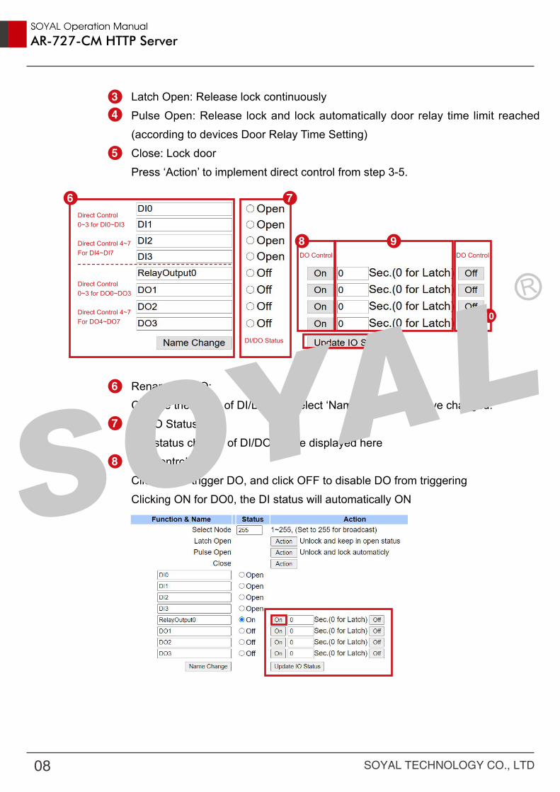
Latch Open: Release lock continuouslyPulse Open: Release lock and lock automatically door relay time limit reached (according to devices Door Relay Time Setting)Close: Lock doorPress ‘Action’ to implement direct control from step 3-5.
Rename DI/DO:Change the name of DI/DO and select ‘Name Change’ to save changed.DI/DO Status:The status change of DI/DO will be displayed hereDO Control:Click ON to trigger DO, and click OFF to disable DO from triggeringClicking ON for DO0, the DI status will automatically ON
6Direct Control 0~3 for DI0~DI3
Direct Control 4~7For DI4~DI7
Direct Control 0~3 for DO0~DO3
Direct Control 4~7For DO4~DO7
DI/DO Status
DO Control DO Control
7
8
10
9
11
SOYAL TECHNOLOGY CO., LTD
SOYAL Operation Manual
AR-727-CM HTTP Server
08

Clicking OFF for DO0, the DI status will automatically returned to OFF status
DO Control (Output Time)Change the Output Time of DO control between the range of 0~600 seconds.Entering 0 means latch mode, output continuously.Entering between 1~600 seconds means output ON according to output time set.
Update IO Status: Get real time IO current status by clicking Update IO Status
9
10
SOYAL TECHNOLOGY CO., LTD
SOYAL Operation Manual
AR-727-CM HTTP Server
09

CH1 Setting:
CH2 Setting:
1
1
2
2
3
3
3-1 TCP/IP Converter Setting
Wiring SOYAL access controller to PC can be done via RS485 or TCP/IP interface. For SOYAL access controller that built-in RS485, via Industry Series (TCP) or AR-727-CM achieve RS485 to TCP/IP connection.Each device built in two RS485 channels that differentiate between CH1 and CH2.
1
1
2
2
3
3
Protocol : TCPOperation Mode: ServerLocal Port 1621
Default Value Protocol UDP change into TCPOperation Mode: ServerLocal Port 1623
3. Interface Overview
SOYAL TECHNOLOGY CO., LTD
SOYAL Operation Manual
AR-727-CM HTTP Server
10

3-2 Fire Alarm Auto Release Doors
SOYAL provides various options for Fire Event Solution. This is taking a consideration of onsite situation and human safety when escaping fire and evacuation while maintaining safety for authorized area.SOYAL Fire Alarm Auto Release Doors available on AR-727-CM-0804M & AR-401-IO-0808R-U2 using its onboard DI0 specifically made for Fire Event. There are two modes to choose: Auto Alarm Auto Release Doors via RS485 method and UDP method. For each mode, there are two options available to release locks via broadcast (release all doors) and release only specified doors.Releasing all doors is suggested for public spaces where user could directly escape building for safety precaution and quick evacuation process. Meanwhile releasing only a specified doors is suitable to keep doors remain locked for high authorized area or for building with warehouses, treasure room, or server IT room.
3. Interface Overview
SOYAL TECHNOLOGY CO., LTD
SOYAL Operation Manual
AR-727-CM HTTP Server
11

Setting: Selected Node ID enter 255 on the first field, the rest of the field enter 0 to disable (because entering 255 on the first field has enabling broadcast to release all doors open on RS485 CH1)
Release all doors
STEP 1 : Select ‘Channel 1 Setting’STEP 2 : Fire Alarm (DI0) Open Doors: ‘Enable’STEP 3 : Door Open Mode Select ‘Keep Latch’STEP 4 : Select broadcast or specified group of doors to release lock under Fire Event (each RS485 Channel could specified up to 8 doors). The specified station number range between Node ID 1-254.
● 3-2-1 Fire Alarm Auto Release Doors (RS485 method)
3. Interface Overview
4
1
23
SOYAL TECHNOLOGY CO., LTD
SOYAL Operation Manual
AR-727-CM HTTP Server
12

Setting: Example shows release doors only for the affected floors (up and below) or specified floor Node ID 1 and Node ID 6 via RS485 CH1
Release specified doors only
● 3-2-2 Fire Alarm Auto Release Doors (UDP method)
Compatible Controller: Enterprise Series Controller.Enterprise Series controller could accept “Release door lock” command via UDP from any of the serial servers AR-727-CM-0804M or AR-401-IO-0808R-U2 (required customized firmware, refer to Ref 3.)The condition to this setup is only available for Enterprise Series Controller with Ethernet connection and under the same intranet.
Setting:Each of the controller’s Secondary DNS Server set to 0.0.0.0
Release all doors
3. Interface Overview
SOYAL TECHNOLOGY CO., LTD
SOYAL Operation Manual
AR-727-CM HTTP Server
13

3. Interface Overview
Setting:Each of the controller’s Secondary DNS Server that will accepts “release door lock command” set as specified IP address of the serial servers AR-727-CM-0804M or AR-401-IO-0808R-U2.
Under AR-727CM-IO, the lift access controller supports connection to Fire Alarm. With special firmware, in normal situation, when users swipe RFID tags, the controller’ s relay doesn’t act. It only acts once receiving fire alarm signal. Relay is controlled by fire alarm signal instead of valid tags.
This function is available at the firmwares:725E-V2: APS725Ev2__V0403_200415 ACCESS_DONT_OPEN_DOOR.STM725HD: 725HD_7V3 190530 ACCESS_DONT_OPNE_DOOR.ISP
Release specified doors only
Youtube Video Tutorial regarding Fire Alarm Event Release All Doors
● 3-2-3 Fire Alarm Auto Release Lift Door
SOYAL TECHNOLOGY CO., LTD
SOYAL Operation Manual
AR-727-CM HTTP Server
14

3. Interface Overview
● 3-2-4 Fire Alarm Indicator
Indicator when Fire Alarm Event is happening:DI0 LED will continuous blinking > sensing Fire Alarm EventCH1 or/and CH2 TX red LED will fast blink > Release doors
12
2
1
SOYAL TECHNOLOGY CO., LTD
SOYAL Operation Manual
AR-727-CM HTTP Server
15

3. Interface Overview
3-3 TCP/IP Remote I/O Control Setting
Remote I/O Control Setting is a function where when DI is triggered, the DO with linkage control will control remote device or sending a warning (i.e: if temperature in a factory is too high, it will send alert to AR-727CM-IO, the network linking to a remote fan that connected to AR-727CM-IO too, will activate ventilation system and send an alarm to Emergency Status Board in Main Factory).Conditions: Both serial servers AR-727-CM-0804M or AR-401-IO-0808R-U2 that will operate interlinkage IO control must be on intranet or the same subnet mask, or implement connection using VPN. Required customize firmware for this feature (refer to Ref 4.) One-to-one control, fixed direction control
Serial Server A → Serial
Server B
DI0 → DO0
DI1 → DO1
DI2 → DO2
DI3 → DO3
SOYAL TECHNOLOGY CO., LTD
SOYAL Operation Manual
AR-727-CM HTTP Server
16

3. Interface Overview
3-4 Server-Client Mode Communication Bridge
Setting:Example Serial Server A IP Address is 192.168.1.170 and Serial Server B IP Address is 192.168.1.174Set Serial Servers A as ServerSTEP 1 : Operation Mode: Set as ServerSTEP 2 : Local Port: Enter 1621STEP 3 : Remote Port: Enter 1621STEP 4 : Remote IP: Enter Serial Server B IP Address 192.168.1.174STEP 5 : There is no need to do any set up for Converter B
Industry Series (TCP) AR-727-CM-0804M, AR-401-IO-0808R-U2 and AR-727-CM converter offer a communication bridge as Server-Client Mode that could solve issue with:
1. Master and Slave Reader cable wiring into wireless
1
23
4
Youtube Video Tutorial regarding TCP/IP Remote IO Control Setting
SOYAL TECHNOLOGY CO., LTD
SOYAL Operation Manual
AR-727-CM HTTP Server
17

2. Data transfer between two devices via TCP/IP
SETTINGAR-727CM CLIENT MODE
(for MASTER RS485 DEVICE)AR-727CM SERVER MODE(for SLAVE RS485 DEVICE)
NETWORK SETTING
IP Address: 192.168.1.174 IP Address: 192.168.1.171 (Remote IP)
CH 1& CH2 SETTING
Protocol = TCPOperation Mode = Client
Remote Port for CH1 = 1621;Remote Port for CH2 = 1623Remote IP: 192.168.1.171
(Server Mode AR-727CM’ s IP for Slave RS485 devices)
Protocol = TCPOperation Mode = Server
Remote IP = 0.0.0.0
3. Interface Overview
SOYAL TECHNOLOGY CO., LTD
SOYAL Operation Manual
AR-727-CM HTTP Server
18

3-5
4-1
Change Login Password
FAQ
4. References
1
23
4
STEP 1 : Select ‘User Password’STEP 2 : Enter new password (there’s capital letter differentiation)STEP 3 : Retype the new passwordSTEP 4 : Press Update button to save changed.
Q 1 : How many units of access controller that can be connected to each of RS485 channel? A : There is no limitation to it but we suggest to wire up to 8 units access controller per channel, combining both channel up to 16 units access controller per unit of AR-727- CM/Industry Series (TCP). Q 2 : How long wiring distance of RS485? A : RS485 wiring can support up to 1000M, but due to environment conditions the suggested wiring distance is 300M (parallel wiring), more than that please consider purchasing RS485 signal enhancer AR-RS485REP.Q 3 : What cable type for RS485 wiring? A : We recommend using twist AWG22 cable
3. Interface Overview / 4. References
We connect controller to CH2 of 727CM, but there is no response from PC. Why?
How to use DHCP function for 727CM?
SOYAL TECHNOLOGY CO., LTD
SOYAL Operation Manual
AR-727-CM HTTP Server
19

4. References
Firmware of AR-727-CM in different applications:(latest firmware version will keep updated, contact SOYAL team for more information)
Ref no. Functions Firmware Version
Ref 1. Support Modbus protocol APX727i3___V0500 8I4O 201112 MODBUS_TCP.STM
Ref 2. Support TCP/IP to Wiegand Converter APX727i3___V0500 8i4o WG Converter 200417.STM
Ref 3. Fire Alarm Event UDP Mode APX727i3___V0500 8I8O 190930 UDP FireMessage.STM
Ref 4. TCP/IP Remote I/O Control Setting APX727i3___V0500 200814 MODBUS_TCP DI03_Trigger_DO03.STM
4-2
4-3
YouTube Videos
Firmware
《Product Application》TCP/IP Remote IO Control Setting
《Peripheral expansion application》Release locks Solution in Fire Alarm Event(2018)
《Peripheral expansion application》Release locks Solution in Fire Alarm Event(2017)
SOYAL TECHNOLOGY CO., LTD
SOYAL Operation Manual
AR-727-CM HTTP Server
20