operation & installation manual ais-ctrx class … · ais-ctrx class b ais transponder manual...
TRANSCRIPT

OPERATION & INSTALLATION
MANUAL
AIS-CTRX Class B AIS Transponder
OFFICIAL AIS SUPPLIER TO VOLVO OECAN RACE
Version 1.6E
© True Heading 2009
The manual may not in any aspect be copied without the prior authorization from True Heading AB.

AIS-CTRX Class B AIS Transponder Manual
1.2E 2 AIS-CTRX Manual
TABLE OF CONTENTS
TABLE OF CONTENTS ............................................................................................. 2
REVISION .................................................................................................................. 4
INTRODUCTION ........................................................................................................ 5
GLOSSARY ................................................................................................................ 6
CONDITIONS ............................................................................................................. 8
WARRANTY ............................................................................................................... 9
General .................................................................................................................... 9
Warranty conditions ................................................................................................. 9
Warranty procedures ............................................................................................... 9
Other issues ............................................................................................................ 9
SUPPORT ................................................................................................................ 10
GENERAL NOTICE .................................................................................................. 11
LICENSING .............................................................................................................. 12
INFORMATION ABOUT AIS .................................................................................... 13
General .................................................................................................................. 13
Short technical description of AIS .......................................................................... 14
Limitations with AIS ............................................................................................... 15
PRODUCT SPECIFICATION ................................................................................... 16
Declaration of Conformity ...................................................................................... 17
INSTALLATION: AIS-CTRX .................................................................................... 18
Getting started. ...................................................................................................... 18
BEGIN THE INSTALLATION .................................................................................... 20
CONNECTION TO A PLOTTER ............................................................................... 25
HOW TO PROGRAM AIS-CTRX .............................................................................. 32
HOW TO USE AIS-CTRX ......................................................................................... 46
FAQ .......................................................................................................................... 50
NOTES ..................................................................................................................... 53
DRAWINGS .............................................................................................................. 54
AIS-CTRX Class B AIS Transponder Manual
1.2E 3 AIS-CTRX Manual
Packing List ........................................................................................................... 54
Fixing Template (NOT TO SCALE) ....................................................................... 55
General Arrangement ............................................................................................ 56
Cable Assemblies .................................................................................................. 56
APPENDIX A ANTENNAS AND ANTENNA MOUNTING ...................................... 58
GPS Antenna ......................................................................................................... 58
VHF antenna for AIS use ....................................................................................... 58
WARNINGS ........................................................................................................... 58

AIS-CTRX Class B AIS Transponder Manual
1.2E 4 AIS-CTRX Manual
REVISION
Version Date Responsible Approved Changes
P1.0E 2008-08-19 Anders Bergström Nils Willart Preliminary release
1.0E 2008-10-17 Anders Bergström Nils Willart First release
1.1E 2009-02-11 Anders Bergström Nils Willart Change of pictures
1.2E 2009-04-01 Anders Bergström Nils Willart Table 1
1.3E 2009-06-30 Anders Bergström Nils Willart Total revision
1.4E 2009-09-02 Anders Bergström Nils Willart New English translation
1.5E 2009-11-12 Anders Bergström Nils Willart New AIS compatible plotters
1.6E 2009-12-14 Anders Bergström Nils Willart Garmin 3005 connecetion

AIS-CTRX Class B AIS Transponder Manual
1.2E 5 AIS-CTRX Manual
INTRODUCTION
We would like to thank you for choosing True Heading AB as supplier of your AIS-CTRX, AIS Class B Transponder. The AIS-CTRX is a high quality AIS Class B Transponder using the latest technology. AIS-CTRX makes it possible to receive information from ships, buoys, lighthouses, SAR helicopters, Coastguard units, Pilot boats, Weather station etc. and to send information about your own ship to others that are equipped with Automatic Identification System (AIS) transponders or receivers. SEE AND BE SEEN
It is today, according to the IMO SOLAS regulation a requirement for all ships above 300 GT to carry AIS. This means that a large number of ships and other types of navigational information providers will be seen by your AIS-CTRX and contribute to enhanced safety in your navigation.
Picture 1 Real traffic scenario between Sweden and Bornholm (Denmark)
It is of utmost importance that you read this manual before you start to install and use your AIS-CTRX.
AIS-CTRX Class B AIS Transponder Manual
1.2E 6 AIS-CTRX Manual
GLOSSARY
ACA (AIS) Regional Assignment Channel Assignment Message
ACK Acknowledgement
ACS (AIS) Channel management information source messages
AFSK Audio frequency-shift keying
ALR (AIS) Alarm Message
A to N Aid to Navigation
AIS Automatic Identification System
ATC Air Traffic Control
BIIT Built In Integrity Testing
BNC Bayonet fitting type RF connector
CSTDMA Carrier Sense Time Division Multiple Access
COG Course over Ground
CR Carriage Return
CS Carrier Sense
CSTDMA Carrier Sense TDMA
DC Direct Current
DGNSS Differential Global Navigation Satellite System
DGPS Differential Global Positioning System
DSC Digital Selective calling
ETA Estimated Time of Arrival
GALILEO European equivalent to GPS
GLONASS Global Navigation Satellite System
GNSS Global Navigation Satellite System
GMSK Gaussian Minimum Shift Keying
GPS Global Positioning Satellite / System
HF High Frequency
IMO International Maritime Organization
IEC International Electrotechnical Commission
LED Light Emitting Diode
LF Line Feed
LNA Low-noise amplifier
MF Medium Frequency
MKD Minimum Keypad and Display
MMSI Maritime Mobile Service Identity
MPE Maximum Permissible Exposure
NM Nautical Mile = 1852 m
NMEA National Marine Electronics Association
PC Personal Computer
AIS-CTRX Class B AIS Transponder Manual
1.2E 7 AIS-CTRX Manual
PI Presentation Interface
RF Radio Frequency
RTCM Radio Technical Commission for Maritime Services Commission
RX Receive or Receiver
RFI Radio frequency interference
SAR Specific Absorption Rate
SELV Separated Extra Low Voltage
SMA Swedish Maritime Administration
SMS Short Message System
SOG Speed over Ground
SOLAS Safety Of Life At Sea
SOTDMA Self Organized Time Division Multiple Access.
SRM Safety Related Message
SRT Software Radio Technology
TDMA Time-division Multiple Access
TNC Threaded type BNC connector
TX Transmit or transmitter
UTC Universal Time Co-ordinated
VDM (AIS) VHF Data Link Messages
VDO (AIS) VHF data link own vessel messages
VHF Very High Frequency
VTS Vessel Traffic Services (Like ATC but for ships)
VSWR Voltage Standing Wave Ratio

AIS-CTRX Class B AIS Transponder Manual
1.2E 8 AIS-CTRX Manual
CONDITIONS
Before you start using the AIS-CTRX product from True Heading AB it is important that you read and fully understand the installation manual and its instructions. You should only proceed with the installation if you are confident that you will be able to do so.
True Heading AB cannot be held liable for any injury or damage caused by, during or because of the installation of AIS-CTRX. The AIS-CTRX is used at your own risk and it shall be remembered that AIS and GPS data depends on the full co-operation of other users and systems.
AIS-CTRX is a navigation aid and works in co-operation with other similar systems like e.g. radar, optical lookout etc. The AIS-CTRX installation should be inspected from time to time and checked on its operational quality frequently by the user. Remember that navigation and life at sea always requires proper seamanship and that the AIS-CTRX is not a replacement for such qualities.
NOT ALL VESSELS CARRY AIS. IT IS THEREFORE IMPORTANT TO KEEP PROPER LOOKOUT AT ALL TIMES AND TO USE ALL AVAILABLE MEANS TO AVOID COLLISIONS AND ACCIDENTS.
GPS MAY FROM TIME TO TIME INCLUDE ERRORS: THEREFORE, THE POSITION RECEIVED FROM THE GPS BUILT IN TO AIS-CTRX SHALL ALWAYS BE VERIFED WITH OTHER AVAILABLE MEANS.

AIS-CTRX Class B AIS Transponder Manual
1.2E 9 AIS-CTRX Manual
WARRANTY
General
AIS-CTRX is developed and manufactured to meet high technical requirements and user demands. If installed correctly and with regular maintenance your AIS-CTRX should provide you with several years of operation and a very useful product. For further information provided in the manual and in this information sheet please consult the place where you purchased the AIS-CTRX or direct to our support.
Warranty conditions
- The warranty belongs to the person that purchased the product and cannot be handed over to a third party or person.
- The warranty is not valid if serial number is missing, seals broken or if the AIS-CTRX has been incorrect installed. Neither is the warranty valid if instructions for connection have not been followed, faults caused by wrong usage, own made modifications or service made from none authorized service stations.
- True Heading AB acknowledges that AIS-CTRX at delivery has been controlled and found operational.
- True Heading AB agrees to repair or replace any faulty unit without any cost according to the conditions set forth during a period of two (2) years from day of purchase.
- The warranty includes replacement or repair of faulty unit due to error in components or errors in relation to the production of the product.
- The warranty covers costs for spares, labor, and return shipment. It does not include shipment from to the repair facility.
- True Heading AB will never be liable under the warranty conditions for incorrect use, misuse, and incidental, indirect or consequential damages of the AIS-CTRX.
- Proof of purchase is required for any warranty claim of the AIS-CTRX.
Warranty procedures
True Heading AB repairs and replaces faulty parts or units. The customer is responsible for transport of the defect part or unit to True Heading or its retailer.
Warranty claims shall be made to the place where AIS-CTRX was purchased or direct to True Heading AB through mail, fax or e-mail to our support department.
Other issues
Proper seamanship and common sense is applicable when using AIS-CTRX and the products shall only be seen as a navaid. True Heading AB keeps the right to change the specification of the product without prior notice.
IF YOU ARE NOT ABLE TO ACCEPT THE TERMS ABOVE, PLEASE RETURN THE AIS-CTRX TO YOUR RETAILER FOR FULL CREDIT BEFORE OPENED AND USED.
AIS-CTRX Class B AIS Transponder Manual
1.2E 10 AIS-CTRX Manual
SUPPORT
If you need support, please contact the closest reseller or the location where you acquired the product.
The manufacturer can also give support direct:
Email: [email protected] or Fax: +46 8 54593900.
In order to ensure receipt of important information and to protect your guarantee you can register your AIS-CTRX purchase at True Heading AB by sending an e-mail to [email protected] where you indicate series numbers, purchase dates, your name, address and where you bought your equipment.
In accordance with our policy to always offer development and enhancements of our products, and future versions of AIS-CTRX may differ somewhat from this manual. Updated versions of the manual are always available for download at our homepage www.trueheading.see .
The information in this manual is subject to change without prior notice or information thereof.
© 2009 True Heading AB

AIS-CTRX Class B AIS Transponder Manual
1.2E 11 AIS-CTRX Manual
GENERAL NOTICE
The Automatic Identification System (AIS) unit mostly utilise a Global Navigation Satellite System (GNSS) system such as e.g. GPS or GLONASS to determine position.
The accuracy of these systems is variable and can be affected by factors such as the positioning of the antenna, the number of satellites available to determine a position and for how long satellite information has been received.
It is desirable as often as possible to verify both your vessel’s AIS derived position data and other vessels AIS derived position data with visual or radar based observations.
The compass safe distance of this unit is 0.5m or greater for 0.3° deviation.

AIS-CTRX Class B AIS Transponder Manual
1.2E 12 AIS-CTRX Manual
LICENSING
IMPORTANT: In most countries the operation of an AIS unit is included under the vessels marine VHF radio licence provisions. The vessel on to which the AIS unit is to be installed must therefore possess a valid VHF radiotelephone licence which lists the AIS system and the vessel Call Sign and MMSI number.
Please contact the relevant authority in your country for more information.
In accordance with our policy of continuous development and product improvement the AIS-CTRX hardware and/or software may be upgraded from time to time and future versions of the AIS-CTRX may therefore not correspond exactly with this manual.
When necessary upgrades to the product are made, these will be accompanied by updates or addenda to this manual.
Please take time to read this manual carefully to understand its contents fully so that you can install and operate your AIS system correctly.
Information contained in this manual is liable to change without notice.
True Heading AB disclaims any liability for consequences arising from omissions or inaccuracies in this manual and any other documentation provided with this product.
© 2009 True Heading AB

AIS-CTRX Class B AIS Transponder Manual
1.2E 13 AIS-CTRX Manual
INFORMATION ABOUT AIS
General
AIS (Automatic Identification System) is the name of a system that makes it possible for ships to identify other ships and to monitor ship movements. The reason for implementing the AIS system is for the mariner to obtain more information about ships in the vicinity than what radar is able to provide. AIS gives e.g. information about a ships identity (name, call sign, IMO number and MMSI), size this even for ships behind Island or bends that radar cannot detect.
AIS is used to enhance safety for life at sea, improve safety and efficiency in navigation and protect the marine environment.
AIS-information transmitted from a ship contains of three (3) different main types:
- Static data that was programmed into the AIS equipment at installation and it only needs to be changed if the ship changes its name, flag or undergoes a major refit where size or ship type is changed;
- Dynamic data contains information that automatically is updated from ship sensors like the heading from the Gyro, Position and speed from GNSS equipment. Also navigational status belongs to the group of dynamic data but is updated manually by the crew; and
- Voyage related data that manually is updated by the crew along the voyage.
From the start AIS some times also was referred to as UAIS or as the 4S transponder system that meant Ship to Ship and Ship to Shore.
IMO adopted 1998 a performance standard for AIS within the SOLAS requirement that described in general how AIS should work. Below follows a brief description of the main requirements for AIS from the performance standard:
Automatically provide information to AIS land stations, other ships and airborne units e.g. SAR helicopters about the ships identity, Type of ship, Position, Course, Speed, Navigational status (e.g. under way using engine, at anchor) and other safety related information of importance.
Be able to receive the same type of information from other ships.
Be able to monitor and track other ships.
Exchange information with land based AIS systems.
AIS is an automatic system that continuously and simultaneously transmits on two channels in the maritime VHF frequency band.
AIS can handle several reports in a rapid consecutive flow. To accomplish these AIS uses a technique called Self Organized Time Division Multiple Access (SOTDMA) that guarantees high transmission safety and operational robustness.
AIS also allows for other types of information from e.g. sensors like Gyro, GPS and echo sounders etc. to be transmitted automatically.
Important areas where AIS is used are:
Information exchange between ships within VHF range (normally 20-30 NM) to enhance
safety at sea and to improve situation awareness.

AIS-CTRX Class B AIS Transponder Manual
1.2E 14 AIS-CTRX Manual
Information exchange between ships and AIS land stations as e.g. a VTS that controls and monitors maritime traffic in an area.
Automatic reporting in areas with mandatory reporting of different kinds.
Exchange of safety related information between ships and between ships and land stations.
Services like e.g. meteorological information in real-time from areas of importance, identity and position of floating and fixed aids to navigation to improve identification and navigation.
How AIS Works
The marine Automatic Identification System (AIS) is a location and vessel information reporting system. It allows vessels equipped with AIS to automatically and dynamically share and regularly update their position, speed, course and other information such as vessel identity with similarly equipped craft. Position is derived from a Global Navigation Satellite System (GNSS) network and communication between vessels is by Very High Frequency (VHF) digital transmissions. A sophisticated and automatic method of time sharing the radio channel is used to ensure that even where a large number of vessels are in one location blocking of individual transmissions is minimised, any degradation of the expected position reporting interval is indicated to the user and even if the unit suffers extreme channel overload conditions it will always recover to normal operation.
AIS Classes
There are two classes of AIS unit fitted to vessels, Class A and Class B. In addition AIS base stations may be employed by the Coastguard, port authorities and other authorised bodies. AIS units acting as aids to navigation (A to N) can also be fitted to fixed and floating navigation markers such as channel markers and buoys.
Class A units are a mandatory fit under the safety of life at sea (SOLAS) convention to vessels above 300 gross tons or which carry more than 11 passengers in International waters. Many other commercial vessels and some leisure craft also fit Class A units.
Class B units are currently not a mandatory fit but authorities in several parts of the world are considering this. Class B units are designed for fitting in vessels which do not fall into the mandatory Class A fit category.
The AIS-CTRX is a Class B unit
Position Information Source
As noted above the marine AIS system uses position information derived from networks such as the Global Positioning Satellite (GPS) or the Global Navigation Satellite System (GLONASS) in order to determine the location of the AIS unit and thus the vessel to which it is fitted.
Short technical description of AIS
s, depending on the speed and AIS operates primarily on two dedicated VHF-frequencies (AIS1
– 161,975 MHz and AIS2 – 162,025 MHz). In areas where these two channels are not available, AIS can automatically change to other alternatively available frequencies.
AIS uses two VHF radio channels, where the information is transmitted in short data packages or slots in predefined and synchronized time frames. The dynamic information (position, speed, heading etc) is transmitted in intervals from 2 s up to 10 maneuvers of the transmitting ship were the AIS is mounted. Static and voyage related information (type of ship, size, cargo, destination etc.) is transmitted every sixth minute or upon request from other units. Position, course and speed normally

AIS-CTRX Class B AIS Transponder Manual
1.2E 15 AIS-CTRX Manual
are collected from the same sensor systems that provides the same information used in the navigation e.g. in radars or ECDIS and this is normally based on GPS or DGPS. All ships within VHF coverage will be able to receive AIS data and competent authorities that have installed networks with coastal AIS coverage can receive the information. The capacity for the ships to report is defined by the IMO performance standard to a minimum of 2000 data packages or slots per minute (see picture 2). ITU (Technical Standard for the Universal AIS) has been kind to double this and has provided AIS with 4500 data packages or slots per minute. The transmission is based on the (SO)TDMA (Self-organized Time Division Multiple Access) technique, that allows the system to overload with 400 till 500 % and still give almost a 100 % message throughput between ships that are closer to each other than 8 to 20 nautical miles. In such case the system overloads targets far away will be discriminated in favor of targets close to your own ship. In reality, the system capacity is unlimited and allows for a large number of ships to communicate simultaneously.
Picture 2 The principle of AIS technology on the two radio channels.
Limitations with AIS
You should always be aware that all ship others ships and in particular pleasurecrafts, fishing boats, warships and some coastal stations and VTS centers not will be equipped with AIS. Ships that have been mandated to carry AIS can also under certain conditions turn of there AIS equipment at the master’s disgrace. Therefore it is important to be aware that the information that AIS provides might not be the full and complete picture of the situation around your ship.
Users of AIS must also be aware that transmission of false data can occur and that this will be hazardous not only to your own ship but to other as well. The user is responsible for all data that is entered into the system and for information provided by external sensors. The accuracy of received AIS data is only as good as the information transmitted from the source of information.
You should always be aware that wrong configured or calibrated ship sensors (positions-, speed- or heading sensors) could lead to that wrong information will be transmitted. Dangerous situations can occur if faulty information is shown on another ship.

AIS-CTRX Class B AIS Transponder Manual
1.2E 16 AIS-CTRX Manual
PRODUCT SPECIFICATION
Dimensions: 190 x 135 x 83 mm (L x W x H)
Weight: 1,45 kg
Power: DC (9.6-15.6V)
Average power consumption 4W Peak current rating 2A
GPS Receiver (AIS Internal): IEC 61108-1 compliant
Electrical Interfaces: RS232 38.4kBaud bi-directional
RS422 NMEA 38.4kBaud bi-directional
Connectors: VHF Antenna connector GPS Antenna connector Data cable RS232 is a 9 poled D-sub
The NMEA cable RS422 is a unterminated cable The power cable is an unterminated cable
VHF Transceiver: 1 Transmitter, 2 Receivers
(One receiver time shared between AIS and DSC) Frequency: 156.025 to 162.025 MHz
Output Power: 33dBm ± 1.5 dB
Channel Bandwidth: 25 kHz
Bit rate: 9600 b/s ± 50 ppm (GMSK)
1200 b/s ± 30 ppm (FSK)
RX Sensitivity: -107dBm 25 kHz (Message Error Rate 20%)
Co-Channel 10dB Adjacent Channel 70dB IMD 65dB Blocking 84dB
Environmental: IEC 60945, Operating Temperature: -25ºC to +55ºC
IEC 62287, Section 5, Cat c) exposed to the weather
Compass safe distance: 0.5m or more for 0.3° deviation.
LEDs: Transmission = Green
TX timeout = Yellow Alarm = Red No Transmission (Silent mode) = Blue.

AIS-CTRX Class B AIS Transponder Manual
1.2E 17 AIS-CTRX Manual
Standards
This product complies with all the necessary standards under the European R&TTE directive for Article 3.1(a), 3.1(b), 3.2 and 3.3(e). The following standards have been followed in pursuance of this:
IEC62287-1: 2006-03 Maritime navigation and radiocommunication equipment and systems – Class B shipborne equipment of the automatic identification system (AIS) – Part 1: Carrier-sense time division multiple access (CSTDMA) techniques
IEC60945: 2002-08 Maritime navigation and radiocommunication equipment and systems – General requirements – Methods of testing and required test results
IEC61162-1: Maritime navigation and radiocommunication equipment and systems – Digital interfaces – Part 1: Single talker and multiple listeners
IEC61108-1: GLOBAL NAVIGATION SATELLITE SYSTEMS (GNSS) – Part 1: Global positioning system (GPS) -Receiver equipment - Performance standards, methods of testing and required test results
EN 301 843-1 v2.1: Electromagnetic compatibility and Radio spectrum Matters (ERM); Electromagnetic Compatibility (EMC) standard for marine radio equipment and services; Part 1: Common technical requirements
EN 50383: 2002 Basic standard for calculation and measurement of electromagnetic field strength and SAR related to human exposure from radio base stations and fixed terminal stations for wireless telecommunications system (110MHz – 40GHz)
EN60950-1:2002 Information technology equipment – Safety – Part 1: General requirements
Declaration of Conformity
True Heading AB declares that this product is in compliance with the essential requirements and other provisions of the R&TTE directive 1995/5/EC.
The product carries the CE mark, notified body number and alert symbol as required by the R&TTE directive
The product is intended for sale in the following member states:
Intended Country of Use:
GB FR ES SE
AT NL PT DK
NO BE IT FI
IE LU GR CH

AIS-CTRX Class B AIS Transponder Manual
1.2E 18 AIS-CTRX Manual
INSTALLATION: AIS-CTRX
Getting started.
Before AIS-CTRX is installed, you should check that you have all the equipment you need for the installation and that nothing is missing from your delivery.
AIS-CTRX comes with the following parts:
1pc Yellow AIS-CTRX Class B Transponder (P/N 20070701-1)
1 pc Data and DC cable (P/N 20060701-LD2122)
1 pc CD incl. manual and AIS information; SeaClear navigation program (P/N 20060701-CD)
1pc Data sheet with information about how your AIS-CTRX is connected to other units.
You need the following to get your installation to function (not included):
1 pc VHF antenna or one Class B VHF splitter for use of existing VHF antenna.
1 pc GPS antenna (5V active antenna)
1 pc Circuit breaker for mains power with one 2 A breaker (Important to protect the Transponder)
1 pc BNC (male) antenna plug for connection to transponder's VHF contact.
1 pc TNC (male) antenna plug for connection to transponder's GPS contact.
1 pc antenna plug for connection to the VHF antenna (Included in the True Heading AB package solution).
1 pc antenna plug for connection to the GPS antenna (Type FME for True Heading's package solution).
1 pc antenna cable for the VHF antenna (Type RG58 is recommended up to 10 m.) Type RG58 Low- loss or RG213 is recommended up to 20 m For more than 20 m, use cable type RG214 or better.), 20 m antenna cable is included in True Heading's package solution with VHF antenna).
1 pc antenna cable to the GPS antenna (Type RG58 is recommended up to 10 m. Type RG58 is recommended up to 20 m
1 pc DC cable if needed,
4 pcs mounting screws

AIS-CTRX Class B AIS Transponder Manual
1.2E 19 AIS-CTRX Manual
Mount for the antennae, other installation equipment such as ties, screws, connection materials such as connector blocks.
Before you begin the installation , you should decide where you want to place your AIS-CTRX unit. Note the following:
You should be able to see the 4 LEDs on the Transponder in order to easily be able to easily ascertain that it is working properly.
The transponder should be installed so that the antenna cables will be as short as possible but that it at the same time is easy to connect power and data cables to the equipment using the AIS data.
AIS-CTRX has two data ports. One of them is preferably used for connection to i.e. a plotter (RS422 port), the other for connection to a PC for configuration and maintenance and even for your PC navigation solution (RS232 port). The latter port is already prepared for connection with a serial port on a computer. If you do not have a serial port on your computer, you can use a USB port instead via a so- called serial- to USB converter.
If you use an Class B VHF splitter, make sure that it is connected to the same power source as your VHF.
If you use an separate VHF antenna for AIS, specially adapted antennas are available for AIS frequencies, if you do not choose one of those, a regular VHF antenna for marine band is recommended. Place your VHF antenna as high as possible but at least 2.5-3 m above the water surface. If you have a separate antenna, it must be isolated from other VHF antenna equipment.
GPS antennas shall be placed to have a free upward field of vision with no nearby objects that can reflect the signal. GPS antennas shall not be placed in the vicinity of HF or satellite communications equipment.

AIS-CTRX Class B AIS Transponder Manual
1.2E 20 AIS-CTRX Manual
BEGIN THE INSTALLATION
Once you have unpacked your box and checked that your delivery is complete, proceed with the installation as follows.
Open the cover with the 8 screws and remove it. Do not lose the two cable guides mounted on the transponder and be careful to not disturb the rubber seal between lid and transponder.
Figure 5 AIS-CTRX with the cover off, giving access to antenna and data/DC connection
Under the cover there are connections for VHF, GPS and DATA and DC-feeds. a 15 poled d-sub is mounted on the transponder with the following pin configuration.
Pin Signal COLOR
1 Voltage +12 VDC BROWN (1 square)
2 RS-422 TX A (+) ORANGE
3 RS-422 RX A (+) BROWN
4 Not connected
5 Not connected
6 Not connected
7 Not connected
8 Not connected
9 Voltage 0V /EARTH BLUE (1 square)
10 RS-422 TX B (-) BLACK
11 RS-422 RX B (-) WHITE
12 RS-232 TX Data RED
13 RS-232 RX Data BLUE
14 Signal earth (RS-232) GREEN
15 Not connected
Table 1. Pin configuration on AIS-CTRX data port and DC port.

AIS-CTRX Class B AIS Transponder Manual
1.2E 21 AIS-CTRX Manual
There is also a connection in the middle for the GPS antenna cable, a so- called TNC female and one for VHF to the left of so- called BNC female. The transponder is secured on a bulkhead or deck by means of the four holes that can be found on the edges of the bottom plate. The transponder should be installed so that the four LEDs in the panel window are readily visible for inspection of the AIS-CTRX functions. Furthermore, the transponder might also be placed for easy access to the "S" button to switch the transponder to receive- only mode. To further simplify installation, the AIS-CTRX should be placed to obtain the shortest possible cables, in the following priority: 1. VHF, 2. GPS, 3. Data cables and 4. DC power 12 V. Furthermore, certain other onboard equipment such as generators, compressors or electrical panels can interfere with the transponder, and caution must be taken when installing near any such equipment. The accompanying monitoring program can provide an indication if the transponder is experiencing interference. More about this in the ‖Diagnostics‖ section in the chapter on programming AIS-CTRX.‖. To ensure that maximum performance is obtained, it is important to choose the right antenna cables. For cable lengths exceeding 10 m, a low loss cables should be used, such as type RG214, RG213 or LNX, depending on length. Is also important to use the proper connectors, where crimped connectors are preferred over soldered connections. Ready- to- use 10 m lengths of RG58 type cable can conveniently be used, and different adapter contacts can be connected to the standard connections that sits on the cables. In this way one can simply assemble an easy kit for installation. True Heading provides these cables and connectors when ordering.
Figure 6.1 AIS-CTRX connector inside the cover. From the left BNC (Female) for VHF antenna, TNC (Female) for GPS antenna and 15 poled d-sub connection (Female) for data and DC power supply.
After installation of the antenna, AIS-CTRX should be connected to the application where AIS data from the transponder will be shown. AIS-CTRX has two data ports.

AIS-CTRX Class B AIS Transponder Manual
1.2E 22 AIS-CTRX Manual
Figure 7 AIS-CTRX data and DC cables
One data port is already prepared with a 9 poled d-sub connection from the transponder using RS232. Is ready for simple connection to a computer's serial port. Modern computers, especially laptops, often lack serial ports and usually have only USB ports. If this is the case, a serial / USB converter is required. These are generally available in most computer stores, but True Heading AB can also supply these on request. Use order number USB-1. The converter should have its own Windows driver. Some plotters also require the same data stream as a computer, and we recommend straight serial cable connected to the transporter and then cut on the other end to provide free leads.
Figure 8. USB-1 serial- to USB converter.
Free end for NMEA data (RS422)
Free end for DC power supply 12 VDC
BROWN = PLUS, BLUE= = (EARTH)
9 poled d-sub connection for data (RS232)
15 poled d-sub connection is connected in the transponder

AIS-CTRX Class B AIS Transponder Manual
1.2E 23 AIS-CTRX Manual
Figure 9 Numbering of a DB9 Pin connector (female)
Figure 9 displays the numbering for a 9 poled serial cable (female). A male connector has corresponding but mirror- image numbering.
The other port has no connector but has loose leads that can be connected to a plotter with an optoisolated NMEA port (RS422 port). Below are some examples of AIS-CTRX connected for some of the most common plotter solutions.
The below table displays a summary of connection diagrams for different plotters.
Note that occasionally the colours (the poles) on the plotters can be reversed for a reason that we have not yet deduced. Simply reverse the polarity of the cables. NOTE DOES NOT APPLY TO DC power supply
Because Raymarine only has one NMEA port on their plotter, a multiplexer may be necessary to get data other than AIS at the same time. A multiplexer can be ordered from True Heading AB, order number NDC4-A. Also available with USB NDC4-A-USB
Figure 10 Multiplexer NDC-4 to obtain data from several sources when only one port is available.

AIS-CTRX Class B AIS Transponder Manual
1.2E 24 AIS-CTRX Manual
Figure 11 Example of integration with multiplexer
C70RAYMARINE
VHF
NDC4 PCAIS
USB 38400 Bps
IN= VDM (AIS), RMC
OUT= Waypoints to C70
RS422, 38400 Bps
IN= VDM (AIS) + DSC (VHF)
OUT= RMC to VHF
RS422, 4800 Bps
IN = RMC from (C70)
OUT= DSC to (C70)
RS422, 38400 Bps
OUT= VDM (C70 and PC)
RS232, 38400 Bps
OUT= CONFIG
IN=CONFIG

AIS-CTRX Class B AIS Transponder Manual
1.2E 25 AIS-CTRX Manual
CONNECTION TO A PLOTTER
AIS-CTRX GARMIN RAYMARINE*
Pin Signal Cable
Color
Pin Signal Cable
Color
Signal Cable
Color
1 Voltage +12 VDC Brown
2 RS-422 TX A (+)
AIS DATA OUT Orange 1
Reception Port 2 (A+)**
AIS DATA IN
Brown**
White¤¤
NMEA input (ve)+) common
AIS DATA IN
White
Orange/ White#
3 RS-422 RX A (+) Brown
4 Not connected
5 Not connected
6 Not connected
7 Not connected
8 Not connected
9 Voltage 0V /GND Blue
10 RS-422 TX B (-) Black 2
Reception Port 2 (B-)
AIS DATA IN
Brown/White**
Black¤¤
NMEA input (ve-)
AIS DATA IN
Green
Green/ White#
11 RS-422 RX B (-) White
12 RS-232 TX Data
AIS DATA OUT Red 16
Port 1 Data IN
AIS DATA IN
Brown***
VIOLET¤
Brown/White¤¤¤
13 RS-232 RX Data Blue
14 Signal earth (RS-232) Green 18 Signal earth Black***
15 Not connected
16 Not present
17 Not present
18 Not present
Table 2 Connection diagram
* AIS adapted firmware versions: A and C- series: 4.25, E- series: 3.22 (Not A65)
** GPSmap 4000/5000 series (see manual for details)
*** GPSmap 3000/500/400/300/200 series (see manual for details)
¤ GPSmap 500 port 2 (see manual for details)
¤¤ GPSmap 620/640 (see manual for details
¤¤¤ GPSmap 3005 port 2
# Raymarine C90, C120, C140

AIS-CTRX Class B AIS Transponder Manual
1.2E 26 AIS-CTRX Manual
Figure 12 Connection to a Raymarine E or C series

AIS-CTRX Class B AIS Transponder Manual
1.2E 27 AIS-CTRX Manual
Figure 13 Raymarine E or C series connector and cable color
Figure 14 Connection to a Garmin 3000 series

AIS-CTRX Class B AIS Transponder Manual
1.2E 28 AIS-CTRX Manual
Figure 15 Connection to a Garmin 4000/5000
Figure 16 Connection to a Garmin 500

AIS-CTRX Class B AIS Transponder Manual
1.2E 29 AIS-CTRX Manual
Table 3 Garmin 3000 series connector and cable color
Table 4 Garmin 4000/5000 series connector and cable color

AIS-CTRX Class B AIS Transponder Manual
1.2E 30 AIS-CTRX Manual
Also NorthStar M121, M84 and Lowrance HDS-series can display AIS. The port that shall be used on Northstar is FUEL/NAV port, however, a special cable can be necessary (not clear from their manual).
AIS-CTRX Northstar M121/M84 LOWRANCE HDS series
Pin Signal Cable
Colour
Pin Signal Cable
Color
Signal Cable
Colour
1 Not connected 1
2 RS-232/422 AIS DATA OUT
RED
or
ORANGE
2 AIS DATA IN White
(RX +)
ORANGE
3 Not connected 3
4 Not connected 4
5 Signal earth/
RS422
GREEN
or
BLACK
5 NMEA DATA IN BLACK
(RX -)
GREEN
6 Not connected 6
7 7
8 8
9 9
Table 5 Connection to Northstar M84 alt M121 and Lowrance HDS-5, 7, 8, 10.
There are a number of other plotters that can interface with AIS-CTRX but the above mentioned are the market leaders and those we receive most inquiries about. The following plotter models can also present AIS. See the respective manufacturers manuals for connecting to these products and for which models can use AIS.
Plotter Hemsida
Raymarine C and E series www.raymarine.com
Garmin 292,392,398,492,498,2206,2210,3205,3206,3210, 4000, 5000 www.garmin.com
Geonav 5 Touring www.geonav.it
Furuno NavNet VX2, GP7000F/NT www.furuno.se
HUMMINBIRD 1100 Series (Sw 4.510), 800 & 900 from 2010 www.humminbird.com
Interphase www.interphase.com
Lowrance (HDS-5, 7, 8, 10) www.navico.com
Seiwa www.boatnav.se
Simrad (NX40 & NX45) www.navico.com
Northstar www.navico.com
Table 6 AIS compatible plotters

AIS-CTRX Class B AIS Transponder Manual
1.2E 31 AIS-CTRX Manual
The following PC systems are ready to present AIS. Often, PC based systems are better at presenting AIS and more flexible in updating to new functions that always will be on the way with the AIS system.
Company Website Country
Adveto www.adveto.se Sweden
Admiral Chart www.admiralchart.no Norway
Chartworx www.chartworx.com Holland
Dolphin Maritime Software www.dolphinmaritime.com UK
Euronav www.euronav.co.uk UK
Fugawi www.fugawi.com USA
GateHouse www.gatehouse.dk Denmark
ICAN Marine www.icanmarine.com Canada
Maxsea www.maxsea.fr France
Morintech www.morintech.no Norway
Nobeltec www.nobeltec.com USA
PC Maritime Ltd www.pcmaritime.co.uk UK
SeaClear www.sping.com Sweden
SeaCross www.seacross.se Sweden
Sodena www.sodena.net France
SPI Marine www.spimarine.de Germany
TMQ www.tmq.com.au Australia
Transas www.transas.de Germany
Tridentnav www.tridentnav.se Sweden
Xanatos www.xanatosholdings.com Canada
Y-tronic www.yacht-ais.com Germany
Table 7 AIS- compatible navigation programs for PC.
Now, the DC power supply is all that's left. AIS-CTRX should be connected to a 12 V DC power supply. It is important that the transponder is guarded by a 2 A circuit breaker to protect the transponder. It is important to protect the transponder against high voltage, and earth is not connected via the antenna installation. The transponder is delivered with a cable for DC power supply where the brown cable connects to PLUS and the BLUE the cable to earth.

AIS-CTRX Class B AIS Transponder Manual
1.2E 32 AIS-CTRX Manual
HOW TO PROGRAM AIS-CTRX
AIS-CTRX can only be programmed by an authorised reseller who has a contract with True Heading AB regarding access to programming software DEALER PRO AIS. The data needed in order to be able to program AIS-CTRX correctly are:
MMSI numbers:
Call sign:
Vessel name:
Type of vessel: For example. Pleasure craft
GPS antenna position:
A= Metres
B= Metres
C= Metres
D= Metres
Table 8 Template to generate the correct data to program an AIS-CTRX.
AIS-CTRX should be programmed upon delivery to the user.
The transponder includes END USER PRO AIS software where several functions can be set and valuable diagnostics on the transponders that is can be obtained. Note that END USER PRO AIS cannot be used to program data into the transponder.
PRO AIS is made to function with Windows 2000 and Windows XP (SP2): Windows Vista has not been verified.
When using a serial USB converter, make sure it is completely installed for connecting to the port. PRO AIS uses Microsoft .Net Framework V2.0. This means that the program is updated and installed automatically if it does not already exist.

AIS-CTRX Class B AIS Transponder Manual
1.2E 33 AIS-CTRX Manual
INSTALLATION
1. Insert installation CD and find the file ‖Setup.exe‖. 2. Double- click on the file ‖Setup.exe‖ and start the installation. 3. Follow directions to install .Net framework if so required 4. Once the security alert below appears, select ‖Install‖/‖Installera‖ 5. PRO AIS will be installed and launch automatically. 6. A Start Menu folder will be created with the name ‖proAIS‖.
Figure 17 Installation of proAIS software for monitoring of AIS-CTRX.
INSTALLATION OF ProAIS from the computer ProAIS software can be removed at any time by using ‖Add or Remove Programs‖ under the Control Panel.
Connect proAIS to your AIS-CTRX
In order to begin using a version of PRO AIS with the transponder , the AIS-CTRX must receive 12 V DC power and the serial cable with the 9 poled d-sub contact be connected to a PC where PRO AIS software is installed. If you do not have a serial port on your computer a serial- to USB converter must be used according to the above (see Page 22-23).
When you start the proAIS application, you will to need connect the computer to your AIS-CTRX by choosing the correct communication port where AIS-CTRX is connected by choosing ‖Select serial port‖ and then clicking the icon ‖Connect‖ in the dropdown menu. The computer then connects to the transponder and programmed data will be become visible in the ‖Static data‖ field, shown by default.

AIS-CTRX Class B AIS Transponder Manual
1.2E 34 AIS-CTRX Manual
Figure 18 Connection of PC to AIS-CTRX takes place via choice of the correct port. Select serial port] and then by connecting itself to the transponder [Connect].
AIS-CTRX is connected to proAIS when all static data are presented in the ‖Static data‖ field. If these field are empty, the transponder must be programmed at an authorised dealer using a special program. The menu looks the same but makes it possible to program ‖Ship’s Name‖ ‖Call Sign‖ and ‖MMSI Number‖ which cannot be done by the end user. Placement of the GPS antenna on board is subject to change and ‖Vessel type‖, the type of ship the transponder has been placed on board, can be set in the drop down menu. For all types of leisure craft, we recommend that one chooses the type ‖37 = Vessel -Pleasure craft‖. Furthermore, the placement of the GPS antenna on board shall be indicated from fore to aft and from port to starboard in the field ‖Ship’s dimension & GPS Antenna location‖. If any changes are made, or when programming data into the transponder for the first time, data is stored first after selecting the icon ‖Save data to AIS‖ Note that AIS-CTRX can only be programmed once with static data (MMSI, Name and call sign). If the transponder has been programmed with incorrect data True Heading must be contacted. Before data is stored one is prompted if one is sure that all data is correct before proceeding. This is the last chance to correct any errors, so make absolutely sure that MMSI, Name and Call sign are correctly entered in their respective fields.

AIS-CTRX Class B AIS Transponder Manual
1.2E 35 AIS-CTRX Manual
Figure 19 AIS-CTRX is now connected and one can see that all data is correctly entered. Always reconfirm this before AIS-CTRX is started.
Figure 20 Before AIS-CTRX be programmed, this warning will always appear to ensure that the correct MMSI numbers have been entered.
The next proAIS software menu is ‖GPS status‖ ;check here that the AIS-CTRX transponder's built-in GPS receives GPS data correctly. This tool can conveniently be used during installation to see that the GPS antenna has been placed in a good location for reception and that cables and connections are properly assembled and not damaged. When AIS-CTRX receives GPS signals, a column for each received satellite will be displayed in the diagram. While the columns are blue AIS-CTRX has not locked on a satellite; when the columns switch over to green, lock on the respective satellite is obtained. The transponder needs four or more satellites to be able to start navigating. AIS-CTRX must have GPS data to be able to start to transmit. AIS-CTRX, however, functions as an AIS receiver also without GPS data. The built-in GPS in AIS-CTRX is of good quality and can be used for navigation. It is then important that out-data speed is increased under the tab ‖Commands‖ according to Page 44, Figure 31 .

AIS-CTRX Class B AIS Transponder Manual
1.2E 36 AIS-CTRX Manual
Figure 21 AIS-CTRX before GPS navigation was obtained with 8 satellites in sight.
Figure 22 AIS-CTRX navigating with 8 satellites in sight. On the left you can see position, course and speed over basic and UTC time and the number of satellites used and as be seen.
The next menu in proAIS software is ‖Diagnostics‖. Here you find several functions and tools to check that the AIS-CTRX transponder works properly and facilities to monitor functionality and performance during i.e. installation. In the field ‖AIS Transponder status‖ ,one can check that the transponder has received a correct MMSI number ‖Transponder MMSI valid‖, in the field ‖AIS Transponder status‖ GPS
AIS-CTRX Class B AIS Transponder Manual
1.2E 37 AIS-CTRX Manual
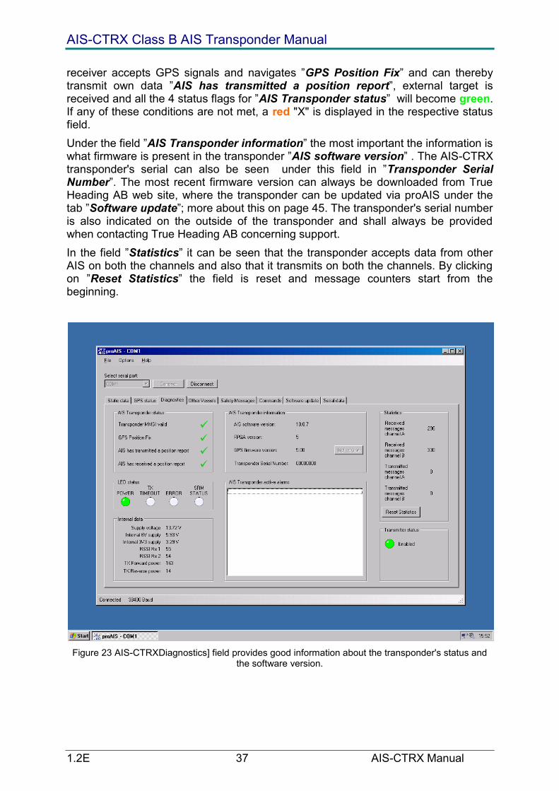
receiver accepts GPS signals and navigates ‖GPS Position Fix‖ and can thereby transmit own data ‖AIS has transmitted a position report‖, external target is received and all the 4 status flags for ‖AIS Transponder status‖ will become green. If any of these conditions are not met, a red "X" is displayed in the respective status field.
Under the field ‖AIS Transponder information‖ the most important the information is what firmware is present in the transponder ‖AIS software version‖ . The AIS-CTRX transponder's serial can also be seen under this field in ‖Transponder Serial Number‖. The most recent firmware version can always be downloaded from True Heading AB web site, where the transponder can be updated via proAIS under the tab ‖Software update‖; more about this on page 45. The transponder's serial number is also indicated on the outside of the transponder and shall always be provided when contacting True Heading AB concerning support.
In the field ‖Statistics‖ it can be seen that the transponder accepts data from other AIS on both the channels and also that it transmits on both the channels. By clicking on ‖Reset Statistics‖ the field is reset and message counters start from the beginning.
Figure 23 AIS-CTRXDiagnostics] field provides good information about the transponder's status and the software version.

AIS-CTRX Class B AIS Transponder Manual
1.2E 38 AIS-CTRX Manual
Figure 24 Before the AIS-CTRX has been programmed, both the yellow and red light diodes will shine both in proAIS and on the LED indicator on the transponder. Yellow and red LED are also displayed if
a serious fault has arisen on the transponder. The most common fault is, however, that the transponder has no valid MMSI, so always reconfirm this first.
The red ‖ERROR‖ the diode can also mean the following: • The transmission has stopped itself (transmitted more than 1 s) and thereby turned itself off. • GPS has not started to navigate after 30 minutes • AIS-CTRX unable to perform standing wave measurement on the antenna. • Background noise is too high which prevents the transponder from transmitting (-77dBm).
Figure 25 The yellow diode will shine in case of some elementary faults, but does not means that the transponder cannot transmit its position to others.
The yellow ‖TX TIMEOUT‖ LED can mean the following faults: • Transponder’s GPS has not started to navigate or does not navigates which means that AIS-CTRX cannot transmit as it has no position data. • Transponder cannot transmit because the channel is busy with another transmitting transponder or because of interference.
Figure 26 The blue LED will shine when AIS-CTRX is set to function only as an AIS receiver, ‖SILENT MODE‖.
The blue ‖SRM STATUS‖ LED means that AIS-CTRX only accepts AIS data and that the transmitter has been set to quiet mode via proAIS or by the blue ‖S‖ button on the transponder being pressed down for 3 seconds.
Figure 27 The green LED means that everything is OK.

AIS-CTRX Class B AIS Transponder Manual
1.2E 39 AIS-CTRX Manual
Figure 28 In the field [Internal data], important information can be obtained about the transponder's status and how the installation is working.
The field ‖Internal data‖ displays a number important data about the transponder's status and installation. ‖Supply voltage‖, ‖Internal 6V supply‖ and ‖Internal 3V3 supply‖ all show that the right voltage is supplied to the transponder. Insufficient voltage on 12 V will of course cause the transponder to stop. Likewise, the transponder can be seriously damaged if the voltage exceeds 16 V. Therefore, always make sure the transponder has proper fuses during installation.
‖RSSI Rx 1‖ and ‖RSSI Rx 2‖ are both data from continuous measurement of the transponder's receiving status. Here, one can in an early stage see if the installation is troubled by interference from other equipment on board or if the interference comes from other transmitting equipment in the vicinity that use the same channel as AIS. If the RSSI values exceed the values around 120-150, the installation should be checked. Example of sources of interference can be generators, electrical panels, refrigerator compressors or other radio equipment. Cables and contacts should also be checked.
Additional information about antenna installation and the transponder's power output can be obtained from the rows ‖TX Forward power‖ (output) and ‖TX Reverse power‖. This standing wave measurement gives an indication if the cables and
AIS-CTRX Class B AIS Transponder Manual
1.2E 40 AIS-CTRX Manual
contacts are properly installed. Output power should be high and lie at values over 120-130 for good function and around 10 for return effect.
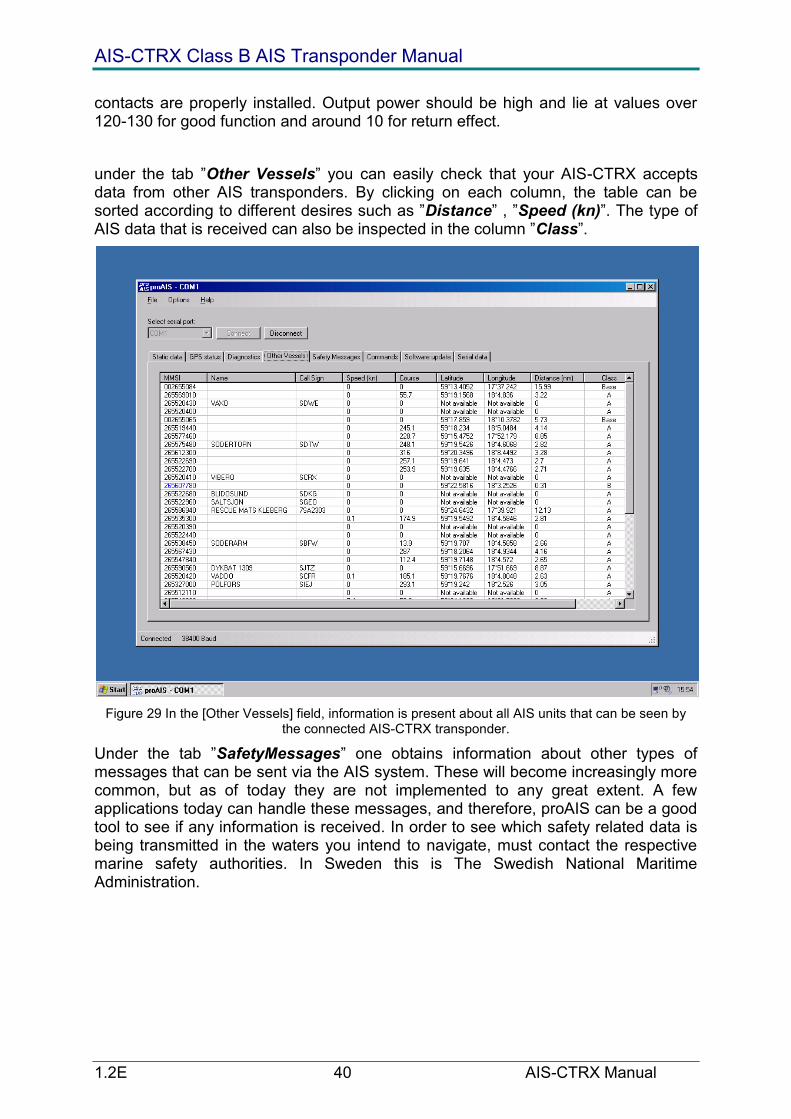
under the tab ‖Other Vessels‖ you can easily check that your AIS-CTRX accepts data from other AIS transponders. By clicking on each column, the table can be sorted according to different desires such as ‖Distance‖ , ‖Speed (kn)‖. The type of AIS data that is received can also be inspected in the column ‖Class‖.
Figure 29 In the [Other Vessels] field, information is present about all AIS units that can be seen by the connected AIS-CTRX transponder.
Under the tab ‖SafetyMessages‖ one obtains information about other types of messages that can be sent via the AIS system. These will become increasingly more common, but as of today they are not implemented to any great extent. A few applications today can handle these messages, and therefore, proAIS can be a good tool to see if any information is received. In order to see which safety related data is being transmitted in the waters you intend to navigate, must contact the respective marine safety authorities. In Sweden this is The Swedish National Maritime Administration.

AIS-CTRX Class B AIS Transponder Manual
1.2E 41 AIS-CTRX Manual
Figure 30 In the field [Safety Messages], information can be obtained about messages that are sent from base stations ashore with i.e. navigational alerts or safety related messages.
Under the tab ‖Commands‖, one adjusts how the AIS-CTRX transponder will feed data to the applications the transponder is intended to be connected to. AIS-CTRX has 2 data ports. In the field ‖Configure Baud rate‖, one adjusts the data transfer rate that these ports will use. AIS shall always use Baud rate 38400 bps (bits per second), otherwise the AIS functionality will become very limited. Normally, ‖RS232 Baud rate‖ port is used for the connection which you make from the computer to the AIS-CTRX transponder via the included9 poled d-sub cable. The other port ‖NMEA Baud rate‖ is preferably used for an NMEA port on a plotter like Garmin or Raymarine, still using 38400 bps. ‖NMEA Baud rate‖ port controls the other port that the AIS-CTRX transponder has, which is the end that is without termination on accompanying DC and Data cable. Orange and Black wires are used for data out from the transponder for connection to plotter, See table. 2, Page 27. The only occasion when another data speed than 38400 bps can be advisable is if the AIS-CTRX transponder shall feed a VHF with position from the GPS receiver (Only for VHF equipment that can process NMEA message RMC for position). Then, the speed shall be 4800 bps but also means that ‖NMEA Baud rate‖ port cannot be used to show AIS on an plotter.
In the field ‖Silent mode‖, AIS-CTRX can be set to be a receiver only by clicking on the icon ‖Enter silent mode”.‖. In order to exit from AIS-CTRX as a receiver only, click on the icon ‖Exit silent mode‖. NOTE that this is a special function in proAIS and that it is separate from the hardware control to quiet mode that can be accomplished from the blue and white ‖S‖ button on the transponder.

AIS-CTRX Class B AIS Transponder Manual
1.2E 42 AIS-CTRX Manual
The field ‖GPS NMEA output options‖ is used to adjust how AIS-CTX will feed position data to your application. If you use the excellent built-in GPS receiver also for navigation or as a backup, ‖Output GPS data every second‖ should always be selected. By default, AIS-CTRX will be set to ‖Output GPS data every four seconds‖. ‖Disable GPS data output‖ should be chosen if you have an application where you already have a GPS connected for navigation and application cannot manage more than one GPS simultaneously (causes that one's own boat jumps between the different GPS the receivers' positions). AIS-CTRX GPS data should be shut off for Raymarine plotters . Intelligent applications can handle several GPS signals at the same time by using primary- and secondary functionality, and thereby have an automatic backup.
The field ‖Alarm NMEA output options‖ need only be used if you connect your AIS-CTRX to a Raymarine system. AIS-CTRX transmits by default a status message that all is like the will in accordance to the AIS Class B standard. Because Raymarine units interpret the status message as an alarm and thereby fills up its alarm buffer so quickly that it becomes full and stops the plotter, AIS-CTRX can be set to only feed out live alarms by setting the alarm message in position ‖Output only active alarms‖.
The field ‖Safety related message text‖ is not used.
All the modifications are applied only after the icon in the respective field ‖Update‖ has been clicked.
Figure 31 In the field [Commands] data from AIS-CTRX can be set to be output in different ways.

AIS-CTRX Class B AIS Transponder Manual
1.2E 43 AIS-CTRX Manual
The field ‖Software update‖ is used to update AIS-CTRX with the latest firmware version. The most recent version is always available on www.trueheading.se (see products/downloads) ‖Select update file‖ and then select from the place where you have stored the downloaded .hex file.
Figure 32 In the field [Software update], AIS-CTRX can are updated to latest version.

AIS-CTRX Class B AIS Transponder Manual
1.2E 44 AIS-CTRX Manual
Figure 33 Via the computer, the proper file containing the software to import into the AIS-CTRX is selected.
Once the right file is selected, this will be seen in the field under ‖Update progress‖ and the update is simply begun by clicking on the icon ‖Start Update‖ Note that the power supply or data connection to the transponder may not be interrupted during the update. If this should occur, the transponder could be damaged and must then be sent to the factory for repair. All program data will remain intact after the update, so no new data entry is required to the transponder has been updated.
Figure 34 Start the update process by choosing [Start Update].
As soon as the update is completed, proAIS will announce that the update process is completed by displaying a new icon ‖Software update completed‖. Click on ‖OK‖ to exit the update. Versions older than 10.0.7.0 will require that the power to the transponder is disconnected when proAIS displays an alert that the update is completed.
Figure 35 Update process completed.

AIS-CTRX Class B AIS Transponder Manual
1.2E 45 AIS-CTRX Manual
The last field in proAIS is ‖Serial data‖, where an experienced installer can see that the transponder is receiving data directly from the AIS-CTRX transponder. The field ‖Enter commands below‖ is also used by authorised retailers to reset the AIS transponder's data if needed. In order to do this, True Heading AB must be contacted first to receive an access code. This requires that the serial number on the transponder is provided. When the code is obtained, it is simply sent into the transponder by clicking on the icon ‖Send‖.
From the field ‖Serial data‖ data can also be recorded and stored to disk in order to be sent to support for analysis of receiver data.
Figure 36 In the field [Serial data] the data the transponder transmits is displayed on its port and from this data, important information can show that the transponder functions correctly.

AIS-CTRX Class B AIS Transponder Manual
1.2E 46 AIS-CTRX Manual
HOW TO USE AIS-CTRX
AIS-CTRX has four (4) LEDs that indicate status on your transponder and help to monitor that all as it should be.
AIS RX YACHT provides more possibilities to improve navigation safety as a complement to i.e. radar and electronic sea charts. The built-in GPS receiver makes AIS RX YACHT a small navigation system together with the SeaClear navigation software that is included. An AIS receiver increases your safety when navigating in the fog and dark. Out at sea, it also provides increased security and support for radar information during i.e. squalls, snow or choppy seas. AIS also lets you see behind islands and peninsulas, giving you a good idea of what's around the corner.
Figure 37 AIS can see behind islands and peninsulas.
The Swedish National Maritime Administration will also be using the land-based AIS grid to transmit safety related messages. These messages will contain information about sudden obstacles in the waterways, navigational warnings, weather information etc.
Weather information will also be transmitted in real-time from strategic places along the coast. This will contain information regarding wind direction and speed, water levels, temperature, currents and tides.

AIS-CTRX Class B AIS Transponder Manual
1.2E 47 AIS-CTRX Manual
Figure 38 Weather information transmitted via AIS in real-time
AIS transponders Class A transmit the following data which can be received by AIS-CTRX:
Static Information Dynamic Information Voyage-related Information
+ Name + Destination
+ Type of vessel + FÖG + Deep draught
+ Call Signal + ETA
+ MMSI numbers + Rate of Turn + Navigational Status
+ IMO numbers + KGV (Heading/True course)
+ Size
Note: Occasionally, certain of the above data may be omitted by the transmitting vessel.
AIS RX YACHT includes the program SeaClear which is presented in a separate menu. As shown below, AIS data can be presented in different sea chart programs. Today, there are a number of different programs on the margin that can display AIS.

AIS-CTRX Class B AIS Transponder Manual
1.2E 48 AIS-CTRX Manual
Figure 39 Example of how AIS is presented in the navigational software with radar overlay NOBELTEC Admiral.
Figure 40 Example of how AIS is presented in the navigational software ADVETO AECDIS.
Figure 41 Examples how AIS is presented in HORIZON software from ICAN.

AIS-CTRX Class B AIS Transponder Manual
1.2E 49 AIS-CTRX Manual
Figure 42 Example of how AIS is presented in the navigational software SeaClear.
Figure 43 Example of how AIS is presented on AIS Yacht.

AIS-CTRX Class B AIS Transponder Manual
1.2E 50 AIS-CTRX Manual
FAQ
In Q: Is it possible to use an existing VHF antenna for my AIS-CTRX?
S: True Heading has a new product making it possible to use an AIS-CTRX together with VHF radio, and a FM radio can also make use of same antenna via this filter. Some deterioration of the range for VHF is inevitable, as the antenna height is extremely important for range, especially on a sailboat where the antenna can be placed on top of the mast. If a separate antenna is used, it should be placed about 3 m above the water for a range of 10 M.
Q: Can an existing GPS antenna be used for my AIS-CTRX, i.e. that which I already have to min plotter?
S: A GPS Signal can also be divided with a splitter but most often a more expensive alternatives compared to installing a separate antenna for the AIS transponder. With AIS-CTRX and a separate GPS antenna, a backup is thus obtained for other GPS systems on board.
Q: What type of GPS and VHF antenna should I use for my AIS-CTRX?
S: The GPS antenna should have the following performance:
Antenna type: RHCP, patch or quadrifilar type.
Current supply: 5V DC
LNA amplification: 10 dB (net gain)
Impedance: 50 ohm
Connector type on AIS-CTRX: TNC male
True Heading AB can deliver with both GPS and VHF antennae that suit your AIS—CTRX perfectly.

AIS-CTRX Class B AIS Transponder Manual
1.2E 51 AIS-CTRX Manual
The VHF antenna shall have the following performance:
Antenna type: Vertical radiator
Antenna amplification: 0 – 3 dBd
Impedance: 50 ohm
There are specially tuned antennae available today for AIS that provide better performance, because the antenna are used only for the AIS transponder. Contact True Heading AB for more information.
Q: Can I connect my AIS-CTRX to my plotter?
S: Today there are a number of plotters that can present AIS or that can receive AIS data. Furuno, Garmin, Interphase, Seiwa, Raymarine and VDO now have support for AIS. Several other plotter manufacturers are working on being able to handle AIS data in a near future. For additional information, about this contact your plotter supplier and inquire about an AIS interface. Just as with PC based programs is there large difference between the suppliers in their ability to handle different AIS messages. See Page 30 for a list of known plotters that can present AIS.
Q: Which sea chart programs can present AIS?
S: Today, most electronic sea chart programs can use AIS. The list below is by no means complete, but will be continually updated on our web site. All programs that can handle the NMEA message VDM will be able to present AIS. AIS consists , however, of a number of messages and different capabilities among the different suppliers is the rule regarding AIS data. Ask your supplier for more information about. Special software is also available, such as AIS YACHT from Y-tronic where AIS is presented as on a radar. See Page 31 for a table of software that can present AIS.
Q: Functions AIS-CTRX with centre networks on board?
S: All networks that can handle NMEA VDM data at 38400 b/s should be able to manage AIS data. Furuno Navnet says it can do this while Raymarine’s Seatalk and Silvas Nexus do not. AIS-CTRX is not yet NMEA 2000 compatible. Ask your supplier for additional information,.
Q: I do not have a serial port on my computer. Can I use data from AIS-CTRX?
S: Today, serial to USB converters can be purchased for about 350 SEK. These can be found at most computer supply stores. True Heading can also supply these if needed. Please inquire about serial to USB converters.

AIS-CTRX Class B AIS Transponder Manual
1.2E 52 AIS-CTRX Manual
Figure 44 Serial to USB converters.
AIS-CTRX Class B AIS Transponder Manual
1.2E 53 AIS-CTRX Manual
NOTES

AIS-CTRX Class B AIS Transponder Manual
1.2E 54 AIS-CTRX Manual
DRAWINGS
Packing List
AIS CLASS B TRANSPONDER
PACKED ASSEMBLY
2
1:1
1 PRODUCTION RELEASE 23/2/06
ITEM SRT PART No. DESCRIPTION QTY
1 LD2095 AIS CLASS B TRANSPONDER UNIT 1
2 NA POLYTHENE BAG 300 x 300 mm 1
3 NA SILICA GEL SACHET 1
4 LD2098 OUTER PACKING CARTON 1
5 LD2099 INNER PACKING (2 ITEMS) 1
6 NA CARTON IDENTIFICATION LABEL 1
7 LD2103 INSTRUCTION MANUAL 1
8 LD2104 INSTALLATION TEMPLATE 1
10 LD2111 UNIT DIMENSIONS DRAWING 1
NA = NOT APPLICABLE
9 LD2110 INSTALLATION DIAGRAM 1
1
2
3
5
5
4
6
7
8
9
10
11 LD2121 POWER CABLE ASSEMBLY, KIT 3 (0.5m LONG) 1
12 LD2134 MOUNTING SCREW KIT 1
11
12
2 MAGNET PACK REMOVED 15/6/06
DRAWN
CHECKED
UNLESS OTHERWISE SPECIFIED
DIMENSIONS ARE IN MILLIMETERS
ANGLES ± 0.5°
0.0 ± 0.2 0.00 ± 0.1
NAME
M. KENDALL
DATE
06/15/06TITLE
SIZE
A1DWG NO REV
FILE NAME: LD2114-2.dft
SCALE: SHEET 1 OF 1
REVISION HISTORY
REV DESCRIPTION DATE APPROVED
SOFTWARE RADIO TECHNOLOGY PLC
WESTFIELD INDUSTRIAL ESTATE
MIDSOMER NORTON, BATH, UK.
BA3 4BS
COPYRIGHT
THIS DRAWING IS NOT TO BE REPRODUCED
WITHOUT WRITTEN PERMISSION FROM SRT PLC.
MATERIAL
FINISH
THIRD ANGLE PROJECTION
REFER TO LIST

AIS-CTRX Class B AIS Transponder Manual
1.2E 55 AIS-CTRX Manual
Fixing Template (NOT TO SCALE)
MOUNTING HOLE FIXING CENTRES TEMPLATE
MOUNTING HOLES IN BASE PLATE
ARE O5.5 TO SUIT M5 SCREWS
FRONT OF UNIT
10
0,0
160,0
DRAWN
CHECKED
NAME
M.KENDALL
DATE
TITLE
SIZE
A4DWG NO REV
FILE NAME: LD2104-2.dft
SCALE: SHEET 1 OF 1
REVISION HISTORY
REV DESCRIPTION DATE APPROVED
SOFTWARE RADIO TECHNOLOGY PLCWESTFIELD INDUSTRIAL ESTATE
MIDSOMER NORTON, BATH, UK. BA3 4BS
UNLESS OTHERWISE SPECIFIED
DIMENSIONS ARE IN MILLIMETERSANGLES ± 0.5°
0.0 ± 0.2 0.00 ± 0.1
24/2/06
LD2104 2
AIS CLASS B TRANSPONDERINSTALLATION TEMPLATE
1:1

AIS-CTRX Class B AIS Transponder Manual
1.2E 56 AIS-CTRX Manual
General Arrangement
Cable Assemblies
LD 2111
AIS CLASS B TRANSPONDER UNIT DIMENSIO NS
2
1:1
1 PRODUCT ION RELEASE 23/02/06
2 BUTTO N C HANG ED TO M EM BRANE SWITC H 15/6/06
10
0,0
30
,01
5,0
16
0,0
19
0,0
17 5,0
13 5,020 ,0
16 0,07 ,5 R 8,0
90
,7
2,0
O 5 ,54 H OLES
DRAWN
CHECKED
UNLES S OTHERWISE SPECIFIED
DIMENSIONS ARE IN M ILLIMETERS
ANGLES ± 0.5°
0. 0 ± 0.2 0 .00 ± 0.1
NAME
M . KENDA LL
DATE
06/15/06TITLE
SIZE
A1DWG NO REV
FILE N AME: LD 2111- 2.dft
SC AL E: SHEET 1 OF 1
REVISIO N HISTO RY
REV DESCRIPTION DATE APPRO VED
SOFTWARE RADIO TECHNO LOGY PLC
WESTFIELD INDUSTRIAL ESTATE
MIDSOMER NORTON, BATH, UK.
BA3 4BS
C O PY RI GH T
TH IS DRAWIN G IS NOT TO BE REPRO DUC ED
WITHO UT WRITTEN PE RMI SSIO N FRO M SRT PLC .
M ATERIAL
FIN ISH
RUBBER SHEET
1m m THICK
G RADE TO BE DECIDED.
TH IRD AN GLE PRO JEC TIO N
POWER CABLE ASSEMBLY
LD 2109

AIS-CTRX Class B AIS Transponder Manual
1.2E 57 AIS-CTRX Manual
POWER AND DATACABLE ASSEMBLY
LD 2122
/BLACK/RED

AIS-CTRX Class B AIS Transponder Manual
1.2E 58 AIS-CTRX Manual
APPENDIX A ANTENNAS AND ANTENNA MOUNTING
GPS Antenna
The GPS antenna used must be of the active type (i.e. it should incorporate an LNA) and must be suitable for marine shipboard applications (index of protection, ruggedness, means of mounting, etc.). An antenna should be selected with a gain (in dB) depending on the length of cable between the antenna and the AIS unit; after subtraction of cable and connector losses a minimum total gain of 25 dB should be available at the AIS-CTRX unit GPS antenna connector.
The GPS antenna to be used for AIS use must be a dedicated antenna, i.e. not shared with any other GPS receiver.
Installation of the GPS antenna is critical for the performance of the built in GPS receiver which is used for timing of the transmitted time slots and for the supply of navigational information should the main navigational GPS fail. We strongly recommend that:
1. The GPS antenna is mounted in an elevated position and free of shadow effect from the ship’s superstructure
2. The GPS antenna has a free view through 360 degrees with a vertical angle of 5 to 90 degrees above the horizon.
3. As the received GPS signal is very sensitive to noise and interference generated by other onboard transmitters, ensure that the GNSS antenna is placed as far away as possible from radar, Inmarsat and Iridium transmitters and ensure the GPS antenna is free from direct view of the radar and the Inmarsat antenna beam.
4. It is also important that the MF/HF and other VHF transmitter antennas are kept as far away as possible from the GNSS antenna. It is good practice never to install a GNSS antenna within a radius of 5 Metres from these antennas.
VHF antenna for AIS use
The VHF antenna employed for AIS use:
Must be a dedicated antenna, i.e. not shared with any other VHF transmitter/receiver.
Must be suitable for marine shipboard applications (index of protection, ruggedness, means of mounting, etc.)
Should be omni-directional and vertically polarised with unity gain (0 dB) with a bandwidth sufficient to maintain VSWR <1.5 over the frequency range 156 – 163 MHz. As a minimum the 3dB bandwidth must cover the two AIS channels and the DSC Channel.
Should be mounted with at least a two metre vertical separation distance from any other VHF antenna used for speech or DCS communication but see also the section ―Radio Frequency Exposure Warning‖ below
Should be mounted at least 2-3 metres above sea level for full performance.
WARNINGS
VHF Antenna Connection
Connecting a badly mismatched VHF antenna, leaving the VHF antenna port disconnected, or shorting the VHF antenna port will activate the VSWR alarm, cause the unit to stop sending position reports or cause damage to the transponder.

AIS-CTRX Class B AIS Transponder Manual
1.2E 59 AIS-CTRX Manual
Radio Frequency Exposure
To meet the requirements for Radio Frequency Exposure it is necessary to install the VHF antenna correctly and operate the AIS equipment according to the instructions.
The table below shows suitable safety distances to other equipment that could cause interference with the AIS Class B Transponder.
Object Safety distance
Radar antenna, X-band 1, 5 m (5 ft)
High efficiency engines 1 m (3 ft)
HF or VHF antennas 3 m (10 ft)
AC power cables with high currency 1 m (3 ft )
Satellite communication antennas 4 m (13 ft)