operation and maintenance manual dsir ce... · logic which indicate the year of manufacture and a ....
TRANSCRIPT
Part No. 20003 Rev - 01
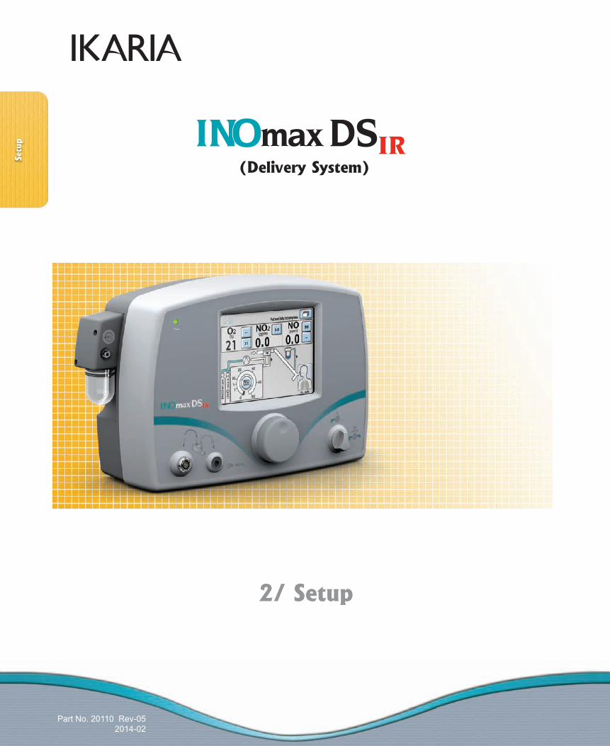
(Delivery System)
Part No. 20110 Rev-052014-02
Operation and Maintenance Manual(English)
Part No. 20110 Rev-052014-02
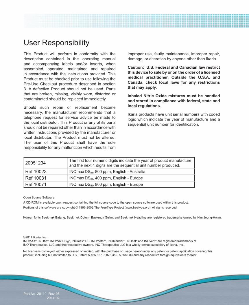
User ResponsibilityThis Product will perform in conformity with the description contained in this operating manual and accompanying labels and/or inserts, when assembled, operated, maintained and repaired in accordance with the instructions provided. This Product must be checked prior to use following the Pre-Use Checkout procedure described in section 3. A defective Product should not be used. Parts that are broken, missing, visibly worn, distorted or contaminated should be replaced immediately.
Should such repair or replacement become necessary, the manufacturer recommends that a telephone request for service advice be made to the local distributor. This Product or any of its parts should not be repaired other than in accordance with written instructions provided by the manufacturer or local distributor. The Product must not be altered. The user of this Product shall have the sole responsibility for any malfunction which results from
improper use, faulty maintenance, improper repair, damage, or alteration by anyone other than Ikaria.
Caution: U.S. Federal and Canadian law restrict this device to sale by or on the order of a licensed medical practitioner. Outside the U.S.A. and Canada, check local laws for any restrictions that may apply.
Inhaled Nitric Oxide mixtures must be handled and stored in compliance with federal, state and local regulations.
Ikaria products have unit serial numbers with coded logic which indicate the year of manufacture and a sequential unit number for identification.
No license is conveyed, either expressed or implied, with the purchase or usage hereof under any patent or patent application covering this product, including but not limited to U.S. Patent 5,485,827, 5,873,359, 5,558,083 and any respective foreign equivalents thereof.
©2014 Ikaria, Inc.INOMAX®, INOflo®, INOmax DSIR
®, INOmax® DS, INOmeter®, INOblender®, INOcal® and INOvent® are registered trademarks of INO Therapeutics, LLC and their respective owners. INO Therapeutics LLC is a wholly-owned subsidiary of Ikaria, Inc..
20051234 The first four numeric digits indicate the year of product manufacture, and the next 4 digits are the sequential unit number produced.
Ref 10023 INOmax DSIR, 800 ppm, English - AustraliaRef 10031 INOmax DSIR, 400 ppm, English - EuropeRef 10071 INOmax DSIR, 800 ppm, English - Europe
Open Source SoftwareA CD-ROM is available upon request containing the full source code to the open source software used within this product.Portions of this software are copyright © 1996-2002 The FreeType Project (www.freetype.org). All rights reserved.
Korean fonts Baekmuk Batang, Baekmuk Dotum, Baekmuk Gulim, and Baekmuk Headline are registered trademarks owned by Kim Jeong-Hwan.
Part No. 20110 Rev-052014-02
1
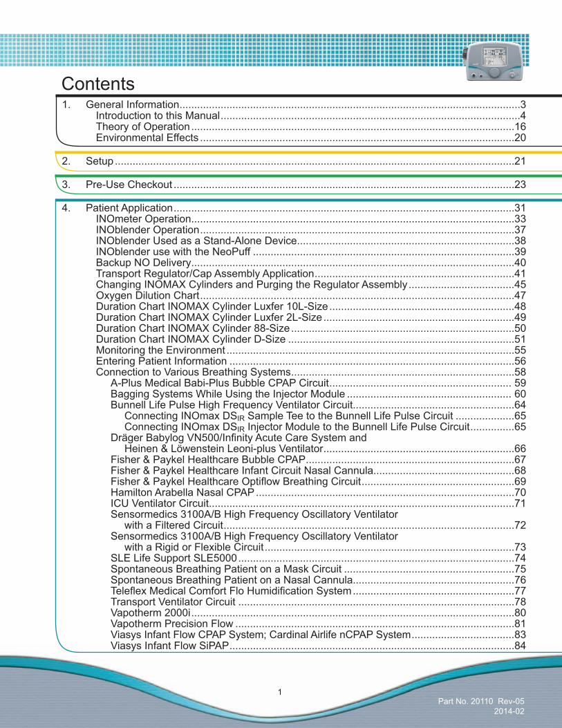
1. General Information ....................................................................................................................3 Introduction to this Manual ......................................................................................................4 Theory of Operation ..............................................................................................................16 Environmental Effects ...........................................................................................................20
2. Setup ........................................................................................................................................21
3. Pre-Use Checkout ....................................................................................................................23
4. Patient Application ....................................................................................................................31 INOmeter Operation ..............................................................................................................33 INOblender Operation ...........................................................................................................37 INOblender Used as a Stand-Alone Device..........................................................................38 INOblender use with the NeoPuff .........................................................................................39 Backup NO Delivery ..............................................................................................................40 Transport Regulator/Cap Assembly Application ....................................................................41 Changing INOMAX Cylinders and Purging the Regulator Assembly ....................................45 Oxygen Dilution Chart ...........................................................................................................47 Duration Chart INOMAX Cylinder Luxfer 10L-Size ...............................................................48 Duration Chart INOMAX Cylinder Luxfer 2L-Size .................................................................49 Duration Chart INOMAX Cylinder 88-Size ............................................................................50 Duration Chart INOMAX Cylinder D-Size .............................................................................51 Monitoring the Environment ..................................................................................................55 Entering Patient Information .................................................................................................56 Connection to Various Breathing Systems ............................................................................58 A-Plus Medical Babi-Plus Bubble CPAP Circuit .............................................................. 59 Bagging Systems While Using the Injector Module ........................................................ 60 Bunnell Life Pulse High Frequency Ventilator Circuit.......................................................64 Connecting INOmax DSIR Sample Tee to the Bunnell Life Pulse Circuit ....................65 Connecting INOmax DSIR Injector Module to the Bunnell Life Pulse Circuit ...............65 DrägerBabylogVN500/InfinityAcuteCareSystemand Heinen & Löwenstein Leoni-plus Ventilator .................................................................66 Fisher & Paykel Healthcare Bubble CPAP .......................................................................67 Fisher & Paykel Healthcare Infant Circuit Nasal Cannula................................................68 Fisher&PaykelHealthcareOptiflowBreathingCircuit ....................................................69 Hamilton Arabella Nasal CPAP ........................................................................................70 ICU Ventilator Circuit ........................................................................................................71 Sensormedics 3100A/B High Frequency Oscillatory Ventilator with a Filtered Circuit ...................................................................................................72 Sensormedics 3100A/B High Frequency Oscillatory Ventilator with a Rigid or Flexible Circuit .....................................................................................73 SLE Life Support SLE5000 ..............................................................................................74 Spontaneous Breathing Patient on a Mask Circuit ..........................................................75 Spontaneous Breathing Patient on a Nasal Cannula.......................................................76 TeleflexMedicalComfortFloHumidificationSystem .......................................................77 Transport Ventilator Circuit ..............................................................................................78 Vapotherm 2000i ..............................................................................................................80 Vapotherm Precision Flow ...............................................................................................81 Viasys Infant Flow CPAP System; Cardinal Airlife nCPAP System ...................................83 Viasys Infant Flow SiPAP .................................................................................................84
Contents
Part No. 20110 Rev-052014-02
2
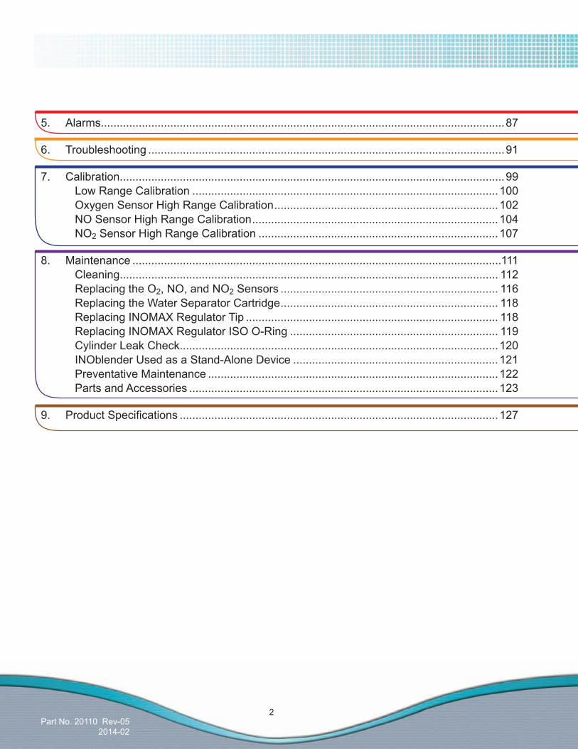
5. Alarms ................................................................................................................................87
6. Troubleshooting .................................................................................................................91
7. Calibration..........................................................................................................................99 Low Range Calibration .................................................................................................100 Oxygen Sensor High Range Calibration .......................................................................102 NO Sensor High Range Calibration ..............................................................................104 NO2 Sensor High Range Calibration ............................................................................107
8. Maintenance .....................................................................................................................111 Cleaning........................................................................................................................ 112 Replacing the O2, NO, and NO2 Sensors ..................................................................... 116 Replacing the Water Separator Cartridge ..................................................................... 118 Replacing INOMAX Regulator Tip ................................................................................ 118 Replacing INOMAX Regulator ISO O-Ring .................................................................. 119 Cylinder Leak Check.....................................................................................................120 INOblender Used as a Stand-Alone Device .................................................................121 Preventative Maintenance ............................................................................................122 Parts and Accessories ..................................................................................................123
9. ProductSpecifications .....................................................................................................127
Part No. 20003 Rev - 01
(Delivery System)
Part No. 20110 Rev-052014-02
1/ General Information
General
Information
(Delivery System)
Part No. 20110 Rev-052014-02
1/ General Information
Gen
eral
Info
rmat
ion

Part No. 20110 Rev-052014-02
3
1/ General Information• TheINOmax DSIR (delivery system) delivers INOMAX
(nitric oxide) for inhalation therapy gas into the inspiratory limb of the patient breathing circuit in a way that provides a constant concentration of nitric oxide (NO), as set by the user, to the patient throughout the inspired breath. It uses a specially designed injector module, which enables tracking of the ventilator waveforms and the delivery of a synchronized and proportional dose of NO. It may be used with most ventilators.
• TheINOmaxDSIR provides continuous integrated monitoring of inspired O2, NO2 , and NO and a comprehensive alarm system.
• TheINOmaxDSIR incorporates a battery that provides up to six hours of uninterrupted INOMAX delivery in the absence of an external power source.
• TheINOmaxDSIR includes a backup NO delivery capabilitythatprovidesafixedflowof250mL/minofNO which along with user supplied 10 L/min of oxygen provides20ppminthegasflowtoapatientsbreathingcircuit. It may also use the INOblender for backup.
• UseoftheINOmaxDSIR is limited to the use in accordance with INOMAX nitric oxide for inhalation prescribing information as approved with the national health authority.
Important:
Before using the INOmax DSIR, read through this manual.
Readthroughthemanualsfortheventilator,humidifierand any other accessory items used. Follow the manual instructions and obey the Warnings and Cautions.
Keep this manual readily available to answer questions.
Read the User Responsibility statement on the inside front cover of this manual; it describes what the user must do to maintain proper use and functioning of this product.
WARNING:Warnings tell you about dangerous conditions that can cause injury to the operator or the patient if you do not obey all of the instructions in this manual.
Caution:Cautions tell you about how to properly use the equipment and conditions that could cause damage to the equipment.
Read and obey all warnings and cautions.
Note:Notesprovideclarificationorsupplementalinformation.
WARNING:• Ifanalarmoccurs,safeguardthepatient firstbeforetroubleshootingorrepairprocedures.
• UseonlypharmaceuticalgradeNO/N2.
• TheINOmax DSIR must only be used in accordancewiththeindications,usage, contraindications,warningsandprecautionsdescribedintheINOMAX(nitricoxide)drugpackage inserts and labeling. Refer to this material prior to use.
• TheuseofdeviceswhichradiatehighintensityelectricalfieldsmayaffecttheoperationoftheINOmax DSIR.Constantsurveillanceofall monitoring and life support equipment is mandatorywheneverinterferingdevicesare in operation on or near a patient.
• INOTherapeuticsdoesnotrecommendthattheINOmaxDSIRbeutilizedwithhelium/oxygenmixturesinanysituation.TheINOmaxDSIRisintendedtodeliverINOMAXtherapy gas only in conjunction with the deliveryofairandoxygen.
• Donotconnectitems,whicharenotspecifiedas part of the system.
Blue arrow denotes required user action.

Part No. 20110 Rev-052014-02
4
Introduction to this ManualDefinitionsandabbreviations
1 2 3
9
68 7 5
11 13 16
1921 20 17
12 14
18
10
Figure 1-1 INOmax DSIR Front View Figure 1-2 INOmax DSIR Rear View
1. Sample Line Inlet2. Main Power Indicator3. Display Screen4. Alarm Speaker (under front label)5. Backup Switch6. Control Wheel7. Injector Module Tubing Outlet
8. Injector Module Cable Inlet9. Water Trap Bottle10. Purge Port11. INOMAX Gas Inlets12. Blender Gas Outlet13. Ethernet Port14. Infrared Connector
22
15. USB Port16. Water Separator Cartridge17. Water Trap Bottle18. Sample Gas Outlet Port19. Power Cord Inlet20. Equipotential Terminal21. ON/Standby Switch22. RS232 Port
% v/v % volume/volumeControl wheel RotarycontrolusedtochangeandconfirmsettingsDisplay The electronic information panel on the front of the delivery systemHFOV High frequency oscillating ventilatorMenu A list of available choices for an operationN2 NitrogenNO INOMAX (nitric oxide) for inhalationNO2 Nitrogen dioxideNO/N2 Nitric oxide (NO) and nitrogen (N2) gas mixtureO2 Oxygenppm Parts Per MillionResolved alarm An alarm condition that has been correctedSet NO The dose of INOMAX set by the userTouch screen A display screen sensitive to touch used to select a function
15
This manual shows the Set NO displays associated with the 0-80 ppm range.4

Part No. 20110 Rev-052014-02
5
4
Figure 1-3 INOmax DSIR and Cart
5
1. INOmax DSIR2. INOmax DSIR Mounting Post3. INOMAX Regulator (2)4. Small Part Bin5. INOMAX Cylinder6. Cylinder Holding Bracket7. Cylinder Mounting Strap8. Oxygen Cylinder Bracket9. Caster Lock Lever10. Caster (4)
7
10
2
3
6
8
9
1

Part No. 20110 Rev-052014-02
6
NavigatingtheDisplayScreensTherearefivescreensthatcanbedisplayedontheINOmaxDSIR.
MainScreen(firstlevel)
Note: ThespecificlevelisidentifiedbythehighlightedcardontheMenuButton. The red arrows indicate going back to a previous screen.
Alarm History Screen(second level)
Menu Screen (second level)Patient Information Screen
Calibration Screen (third level)

Part No. 20110 Rev-052014-02
7
MainDisplayScreen•OntheMainScreen the user can view alarm messages, monitored values and graphical information.
•Bypressingthe“Menu Button” on the touch screen (top right hand corner), the user can access the Menu Screen (see Figure 1-5).
Figure 1-4 Main Display Screen
Figure 1-5 Menu Screen (second level)
MenuScreen(secondlevel)• OntheMenuScreentheuser can change the alarm volume and the display brightness and view the software version.
• ToreviewtheAlarmHistory Screen (second level), refer to Section 5/ Alarms.
• Theusercanalsoselect different calibration options (third level) which are covered in Section 7/ Calibration.
1 2 4
1. Alarm Silence Button2. Upper Alarm Limit Button3. Lower Alarm Limit Button4. Monitored Value5. Menu Button6. Text Message Area
3 5
6
7
8
11 101213141516171819
7. Monitor Area8. Graphical Area9. Patient Information Button10. Sample Line Icon11. Water Trap Icon12. Inspiratory Limb Icon
1 2 4
1. Software Revision Field2. Display Brightness Button3. Alarm Volume Button4. Return to Previous Level Button5. Monitor Area
3
5
6. Calibration Due Dates 7. NO Calibration Button8. NO2 Calibration Button9. Oxygen Calibration Button10. Room Air Calibration Button
910 78
13. Injector Module Icon14. Delivery Line Icon15. Backup Line Icon16. Backup Switch Icon17. Delivery Setpoint Display18. NO Delivery Setpoint Button19. Cylinder Icon
6
9

Part No. 20110 Rev-052014-02
8
Display and user controlsThe INOmax DSIRhasacolortouchscreendisplayandacontrolwheelforadjustingand/orconfirmingusersettings. The buttons on the touch screen and the control wheel perform a variety of functions using a three-step procedure(see“SettingandmakingchangesontheINOmax DSIR”).
When a value is being changed, pressing the "Cancel Active Status" button during editing will stop the change and return the parameter to its original value (similar to the escape key on a computer).
Dose settingsThe range of NO dose settings for the INOmax DSIR isconfiguredbythedistributorforaspecificINOMAX(nitricoxide)concentration,e.g.,400ppmor800ppm.Ifconfiguredfor400ppmtherangeofNOdosesettingis0to40ppmandifconfiguredfor800ppmtherangeis0to80ppm,seebelow.
Each click on the control knob corresponds to a known change in dose. The incremental dose per click corresponds to a value dependent upon the dose range in which the change is made, as illustrated in the table below.
Dose Setting Range Dose Change Per Click 400 ppm
Dose Change Per Click 800 ppm
< 1 ppm 0.1 ppm 0.1 ppm1 to 40 ppm 1 ppm 1 ppm
40 to 80 ppm NA 2 ppm
400 ppm 800 ppm
Note: •If a button has been selected and no activity has been sensed within 20 seconds, the display will return to its previous screen. If a button is de-emphasized (grayed out), it is not accessible.
•Positiondeliverysystemsouserscreenisunobstructedandthespeakerisnotcovered.
Part No. 20110 Rev-052014-02
9
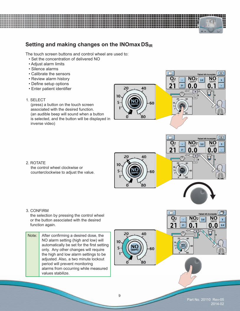
SettingandmakingchangesontheINOmax DSIR
1. SELECT (press) a button on the touch screen associated with the desired function. (an audible beep will sound when a button is selected, and the button will be displayed in inverse video)
2. ROTATE the control wheel clockwise or counterclockwise to adjust the value.
Note: Afterconfirmingadesireddose,the NO alarm setting (high and low) will automaticallybesetforthefirstsetting only. Any other changes will require the high and low alarm settings to be adjusted. Also, a two minute lockout period will prevent monitoring alarms from occurring while measured values stabilize.
3. CONFIRM the selection by pressing the control wheel or the button associated with the desired function again.
The touch screen buttons and control wheel are used to: •SettheconcentrationofdeliveredNO •Adjustalarmlimits •Silencealarms •Calibratethesensors •Reviewalarmhistory •Definesetupoptions •Enterpatientidentifier

Part No. 20110 Rev-052014-02
10
Settings
Access the Menu Screen (second menu level).
Alarm Volume setting1. Push the alarm volume button on the touch screen.
2. Turn the control wheel to indicate the volume level you want. Choices range from 1 (softest) to 5 (loudest).
3. Pushthecontrolwheeltoconfirmyourselection.
4. Ifyouarefinishedwiththe Menu Screen push the return to previous level button on the touch screen.
Display Brightness setting1. Push the display brightness button on the touch screen.
2. Turn the control wheel to indicate the display brightness level you want. Choices range from 1 (darkest) to 10 (brightest).
3. Pushthecontrolwheeltoconfirmyourselection.
4. Ifyouarefinishedwiththe Menu Screen, push the return to previous level button on the touch screen.

Part No. 20110 Rev-052014-02
11
InfraredCommunicationbetweentheINOMAXCylinders andtheINOmaxDSIR
The INOmax DSIR has an interface using infrared (IR) technology which allows the INOmax DSIR to communicate with the INOmeter (which is mounted to each INOMAX cylinder). The INOmax DSIR checks the INOMAX cylinder for the correct expiration date and cylinder concentration. The INOmax DSIRalsotransmitsaconfirmedpatientidentifiertotheINOmeteronany open INOMAX cylinder.
The INOmax DSIR cart has a cover ( ) with an infrared transceiver mounted directly above each INOMAX cylinder. When INOMAX cylinders are loaded, communication will take place between the INOmax DSIR and the INOmeter ( ) after the boot up phase of the INOmax DSIR is complete. A cylinder icon will be displayed on the main screen when an INOMAX cylinder is recognized by the INOmax DSIR(see“LoadingINOMAXCylindersontotheINOmaxDSIR Cart”, page 13).
IR Communication InterferenceThe INOmax DSIR transceiver is located under the cart cover and should be protected from outside IR sources. The INOmax DSIR cart was designed to protect the INOmeter from external light/IR energy sources. The INOmax DSIR transceiver transmits via a 30 degree transmission coneprojectingtowardsthefloor(seedottedlinesinFigure1-6).ThespecificationsoftheIRbeamcallforittohavearangeof20cm(7.9in).Basedonthesespecificationsitwouldnotaffectother devices in the vicinity of the INOmax DSIR.
The INOmeter uses a lower energy source which results in a lower IR beam range than the INOmax DSIR cart. The INOmeter does not transmit IR signals unless it is mounted on the INOmax DSIR cart.
If there is interference with the INOmax DSIR/INOmeter communication, the cylinder icon on the userscreenwillnotbedisplayedanda“CylinderNotDetected”alarmwillactivate.
If IR communication interference occurs, we recommend you take the following actions: •MovetheexternalIRsource•MovetheINOmaxDSIR cart to reduce the external IR source in the area of the INOmeter•ShieldtheINOmeterfromthesuspectIRsource
If the actions listed above do not remedy this issue, the Transport Regulator/Cap Assembly could be utilized (see page 41).
1
2

Part No. 20110 Rev-052014-02
12
12
ExternalLightInterferenceHigh frequency and/or high intensity light emission in the area of the INOmeter may interfere with communication between the INOmax DSIR and the INOmeter on the INOMAX cylinder. If there is interference with the INOmax DSIR/INOmeter communication, the cylinder icon on the user screen will not bedisplayedanda“CylinderNotDetected”alarmwillactivate.
Testresultshavedemonstratedsusceptibilitytounintendedinfraredenergyfromartificiallightsources.Mostnotably,variouscompactfluorescentlightingfixturesthatfocusorreflectlight,increasingthelightintensityinthe vicinity of the INOmax DSIR cart, could affect INOmeter communications.
If external light interference occurs, we recommend you take the following actions:• Movetheinterferinglightsource• MovetheINOmaxDSIR cart to reduce the high intensity light in the area of the INOmeter• ShieldtheINOmeterfromthesuspectlightsource
If the actions listed above do not remedy this issue, the Transport Regulator/Cap Assembly could be utilized (see page 41).
Part No. 20110 Rev-052014-02
13
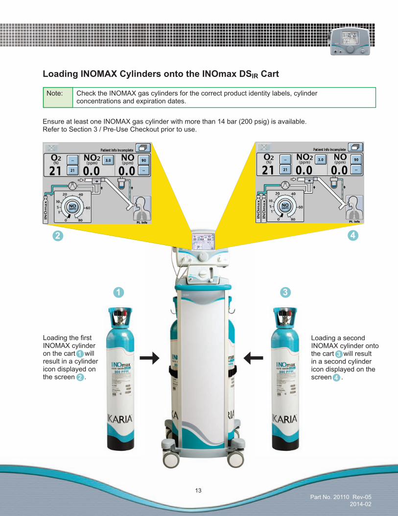
LoadingINOMAXCylindersontotheINOmaxDSIR Cart
Ensure at least one INOMAX gas cylinder with more than 14 bar (200 psig) is available. Refer to Section 3 / Pre-Use Checkout prior to use.
LoadingthefirstINOMAX cylinder on the cart will result in a cylinder icon displayed on the screen .
Loading a second INOMAX cylinder onto the cart will result in a second cylinder icon displayed on the screen .
Note: Check the INOMAX gas cylinders for the correct product identity labels, cylinder concentrations and expiration dates.
3
4
1
2
1
2
3
4

Part No. 20110 Rev-052014-02
14
(Intentionally left blank)
Part No. 20110 Rev-052014-02
15
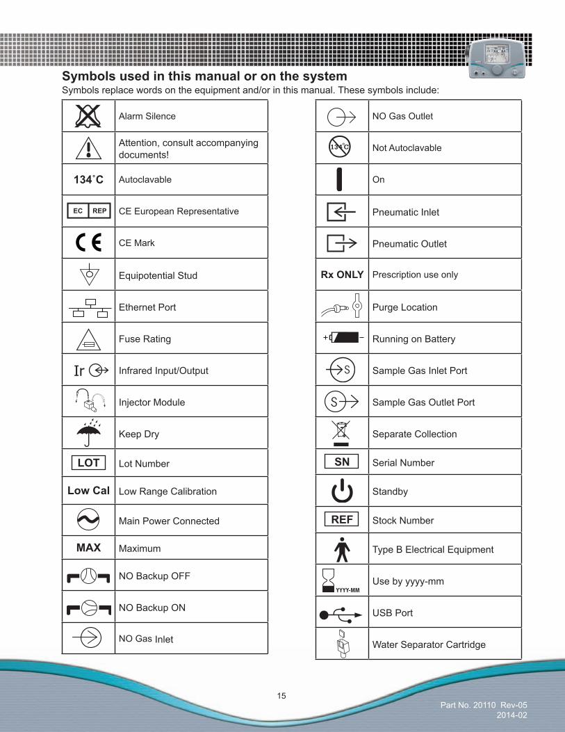
Alarm Silence
Attention, consult accompanying documents!
134˚C Autoclavable
CE European Representative
CE Mark
Equipotential Stud
Ethernet Port
Fuse Rating
Infrared Input/Output
Injector Module
Keep Dry
LOT Lot Number
LowCal Low Range Calibration
Main Power Connected
MAX Maximum
NO Backup OFF
NO Backup ON
NO Gas Inlet
NO Gas Outlet
Not Autoclavable
On
Pneumatic Inlet
Pneumatic Outlet
RxONLY Prescription use only
Purge Location
Running on Battery
Sample Gas Inlet Port
Sample Gas Outlet Port
Separate Collection
SN Serial Number
Standby
REF Stock Number
Type B Electrical Equipment
Use by yyyy-mm
USB Port
Water Separator Cartridge
Symbols used in this manual or on the systemSymbols replace words on the equipment and/or in this manual. These symbols include:
Part No. 20110 Rev-052014-02
16
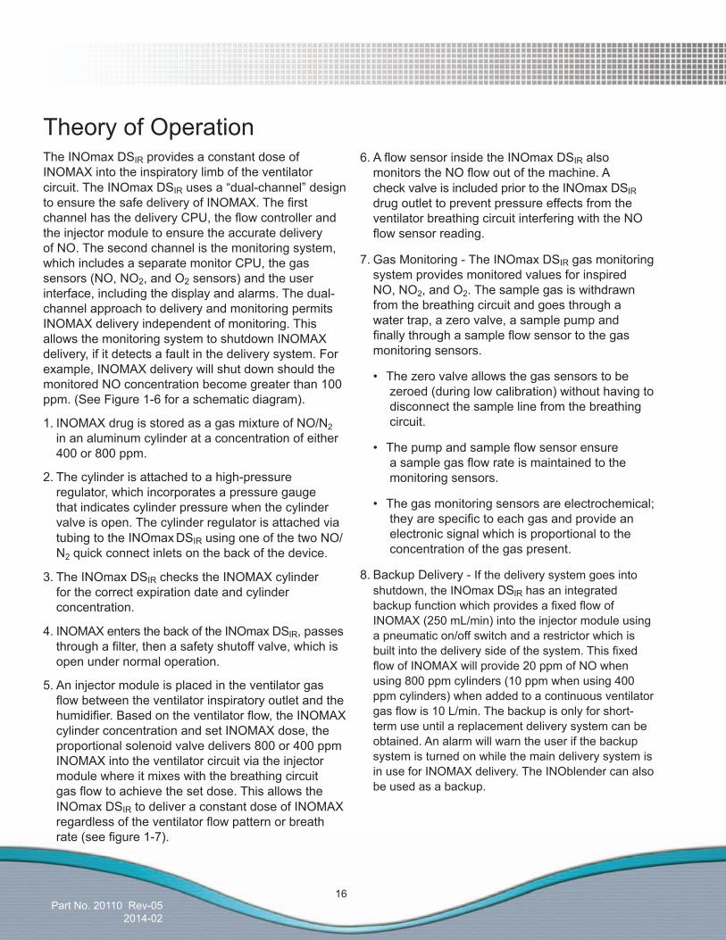
Theory of OperationThe INOmax DSIR provides a constant dose of INOMAX into the inspiratory limb of the ventilator circuit. The INOmax DSIRusesa“dual-channel”designtoensurethesafedeliveryofINOMAX.ThefirstchannelhasthedeliveryCPU,theflowcontrollerandthe injector module to ensure the accurate delivery of NO. The second channel is the monitoring system, which includes a separate monitor CPU, the gas sensors (NO, NO2, and O2 sensors) and the user interface, including the display and alarms. The dual-channel approach to delivery and monitoring permits INOMAX delivery independent of monitoring. This allows the monitoring system to shutdown INOMAX delivery, if it detects a fault in the delivery system. For example, INOMAX delivery will shut down should the monitored NO concentration become greater than 100 ppm. (See Figure 1-6 for a schematic diagram).
1. INOMAX drug is stored as a gas mixture of NO/N2 in an aluminum cylinder at a concentration of either 400 or 800 ppm.
2. The cylinder is attached to a high-pressure regulator, which incorporates a pressure gauge that indicates cylinder pressure when the cylinder valve is open. The cylinder regulator is attached via tubing to the INOmax DSIR using one of the two NO/N2 quick connect inlets on the back of the device.
3. The INOmax DSIR checks the INOMAX cylinder for the correct expiration date and cylinder concentration.
4. INOMAX enters the back of the INOmax DSIR, passes throughafilter,thenasafetyshutoffvalve,whichisopen under normal operation.
5. An injector module is placed in the ventilator gas flowbetweentheventilatorinspiratoryoutletandthehumidifier.Basedontheventilatorflow,theINOMAXcylinder concentration and set INOMAX dose, the proportional solenoid valve delivers 800 or 400 ppm INOMAX into the ventilator circuit via the injector module where it mixes with the breathing circuit gasflowtoachievethesetdose.ThisallowstheINOmax DSIR to deliver a constant dose of INOMAX regardlessoftheventilatorflowpatternorbreathrate(seefigure1-7).
6.AflowsensorinsidetheINOmaxDSIR also monitorstheNOflowoutofthemachine.Acheck valve is included prior to the INOmax DSIR drug outlet to prevent pressure effects from the ventilator breathing circuit interfering with the NO flowsensorreading.
7. Gas Monitoring - The INOmax DSIR gas monitoring system provides monitored values for inspired NO, NO2, and O2. The sample gas is withdrawn from the breathing circuit and goes through a water trap, a zero valve, a sample pump and finallythroughasampleflowsensortothegasmonitoring sensors.
• Thezerovalveallowsthegassensorstobezeroed (during low calibration) without having to disconnect the sample line from the breathing circuit.
• Thepumpandsampleflowsensorensureasamplegasflowrateismaintainedtothemonitoring sensors.
• Thegasmonitoringsensorsareelectrochemical;theyarespecifictoeachgasandprovideanelectronic signal which is proportional to the concentration of the gas present.
8. Backup Delivery - If the delivery system goes into shutdown, the INOmax DSIR has an integrated backupfunctionwhichprovidesafixedflowofINOMAX (250 mL/min) into the injector module using a pneumatic on/off switch and a restrictor which is builtintothedeliverysideofthesystem.ThisfixedflowofINOMAXwillprovide20ppmofNOwhenusing 800 ppm cylinders (10 ppm when using 400 ppm cylinders) when added to a continuous ventilator gasflowis10L/min.Thebackupisonlyforshort-term use until a replacement delivery system can be obtained. An alarm will warn the user if the backup system is turned on while the main delivery system is in use for INOMAX delivery. The INOblender can also be used as a backup.

Part No. 20110 Rev-052014-02
17
Figure 1-6 Schematic Diagram of INOmax DSIR
Figure 1-7 INOMAX injection method provides a constant NO concentration
Time
Delivered Nitric Oxide (NO)Concentration using INOmax DSIRDelivery System
Ventilator Flow
Zero Valve
Regulator
INOMAX
Cylinder
800/400 ppm
Sample Tee
Patient
Sample
Line
Delivery
CPU
Injector
Module
Cable
Injector
Module
Humidifier
INOMAX
Sample Gas
Electronic
Sample Gas Outlet Port
DSIR Link CPU
Injector
Tubing
Infrared
Monitor
CPU
Sensors
O
NO
NO
2
2
Sample Flow
Sensor
Sample Pump
Proportional
Valve
Flow Sensor
Pressure
Switch
Shut Off Valve
NO
Backup
ON/OFF
Restrictor
Shut Off Valve
F FF F
Water TrapVentilator
Breathing Circuit
Expiratory Limb
Inspiratory Limb
Part No. 20110 Rev-052014-02
18
EffectoftheINOmaxDSIRinaventilatorcircuit
There are two main effects of connecting and using the INOmax DSIR in a ventilator breathing circuit.
1. The INOmax DSIR adds NO/N2 gas to the breathing circuit in proportion to the NO setting and the ventilatorflowrate.Forexample,atthemaximumNO setting (80 ppm with 800 ppm cylinders and 40 ppm with 400 ppm cylinders) the INOmax DSIR adds 10% more gas to that delivered by the ventilator and proportionally less for lower NO settings.
2. The INOmax DSIR subtracts gas from the breathing circuit via the gas sampling system at a nominalflowrateof0.23L/min.
Thesetwoeffectsofaddingandsubtractinggasfromtheventilatorbreathingcircuithavethefollowing effects:
OxygenDilution
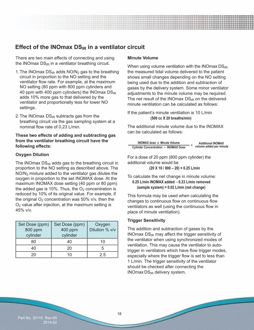
The INOmax DSIR adds gas to the breathing circuit in proportion to the NO setting as described above. The NO/N2 mixture added to the ventilator gas dilutes the oxygen in proportion to the set INOMAX dose. At the maximum INOMAX dose setting (40 ppm or 80 ppm) the added gas is 10%. Thus, the O2 concentration is reduced by 10% of its original value. For example, if the original O2 concentration was 50% v/v, then the O2 value after injection, at the maximum setting is 45% v/v.
Set Dose (ppm) 800 ppm cylinder
Set Dose (ppm) 400 ppm cylinder
Oxygen Dilution % v/v
80 40 1040 20 520 10 2.5
INOMAX dose x Minute VolumeCylinder Concentration -- INOMAX Dose = Additional INOMAX
volume added per minute
MinuteVolume
When using volume ventilation with the INOmax DSIR, the measured tidal volume delivered to the patient shows small changes depending on the NO setting being used due to the addition and subtraction of gases by the delivery system. Some minor ventilator adjustments to the minute volume may be required. The net result of the INOmax DSIR on the delivered minute ventilation can be calculated as follows:
If the patient’s minute ventilation is 10 L/min (500 cc X 20 breaths/min)
The additional minute volume due to the INOMAX can be calculated as follows:
For a dose of 20 ppm (800 ppm cylinder) the additional volume would be (20 X 10 / 800 – 20) = 0.25 L/min
To calculate the net change in minute volume: 0.25 L/min INOMAX added - 0.23 L/min removed (sample system) = 0.02 L/min (net change)
This formula may be used when calculating the changestocontinuousflowoncontinuousflowventilatorsaswell(usingthecontinuousflowinplace of minute ventilation).
TriggerSensitivity
The addition and subtraction of gases by the INOmax DSIR may affect the trigger sensitivity of the ventilator when using synchronized modes of ventilation. This may cause the ventilator to auto-triggerinventilatorswhichhaveflowtriggermodes,especiallywherethetriggerflowissettolessthan 1 L/min. The trigger sensitivity of the ventilator should be checked after connecting the INOmax DSIR delivery system.
Part No. 20110 Rev-052014-02
19
Circle Anesthesia Ventilator Systems
The use of the INOmax DSIR with circle anesthesia ventilator systems (which use volume ventilation) causes small changes in the delivered minute volume as noted previously (see Minute Volume, page 18).
Recirculation of INOMAX in circle breathing systems should be avoided. The gas in the ventilator bellows may also contain undesirable levels of NO2 which may not be removed by the CO2 absorbent.
Recirculation of gases may lead to a rapid increase in INOMAX dose levels resulting in a shutdown of the INOmax DSIR. This can be avoided by using a fresh gasflowrateequaltoorabovethatofthepatient’sminutevolume.Thiswillensurethatthereissufficientfresh gas in the absorber such that no accumulated gas from the ventilator bellows reaches the patient through the inspiratory limb of the breathing circuit.
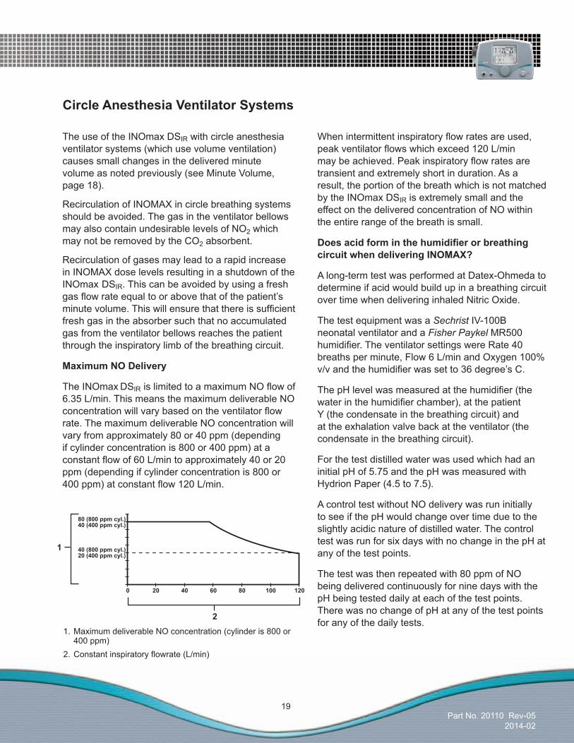
MaximumNODelivery
The INOmax DSIRislimitedtoamaximumNOflowof6.35 L/min. This means the maximum deliverable NO concentrationwillvarybasedontheventilatorflowrate. The maximum deliverable NO concentration will vary from approximately 80 or 40 ppm (depending if cylinder concentration is 800 or 400 ppm) at a constantflowof60L/mintoapproximately40or20ppm (depending if cylinder concentration is 800 or 400ppm)atconstantflow120L/min.
1. Maximum deliverable NO concentration (cylinder is 800 or 400 ppm)2.Constantinspiratoryflowrate(L/min)
Whenintermittentinspiratoryflowratesareused,peakventilatorflowswhichexceed120L/minmaybeachieved.Peakinspiratoryflowratesaretransient and extremely short in duration. As a result, the portion of the breath which is not matched by the INOmax DSIR is extremely small and the effect on the delivered concentration of NO within the entire range of the breath is small.
DoesacidforminthehumidifierorbreathingcircuitwhendeliveringINOMAX?
A long-term test was performed at Datex-Ohmeda to determine if acid would build up in a breathing circuit over time when delivering inhaled Nitric Oxide.
The test equipment was a Sechrist IV-100B neonatal ventilator and a Fisher Paykel MR500 humidifier.TheventilatorsettingswereRate40breaths per minute, Flow 6 L/min and Oxygen 100% v/vandthehumidifierwassetto36degree’sC.
ThepHlevelwasmeasuredatthehumidifier(thewaterinthehumidifierchamber),atthepatientY (the condensate in the breathing circuit) and at the exhalation valve back at the ventilator (the condensate in the breathing circuit).
For the test distilled water was used which had an initial pH of 5.75 and the pH was measured with Hydrion Paper (4.5 to 7.5).
A control test without NO delivery was run initially to see if the pH would change over time due to the slightly acidic nature of distilled water. The control test was run for six days with no change in the pH at any of the test points.
The test was then repeated with 80 ppm of NO being delivered continuously for nine days with the pH being tested daily at each of the test points. There was no change of pH at any of the test points for any of the daily tests.
Part No. 20110 Rev-052014-02
20
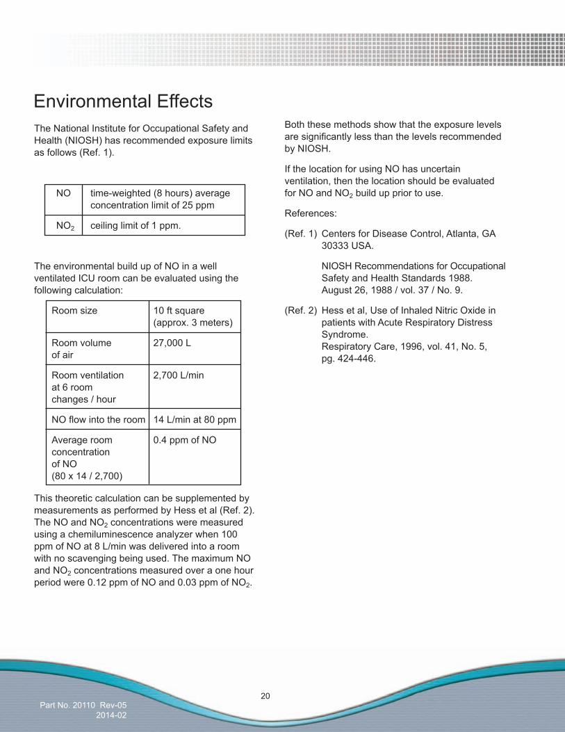
The National Institute for Occupational Safety and Health (NIOSH) has recommended exposure limits as follows (Ref. 1).
NO time-weighted (8 hours) average concentration limit of 25 ppm
NO2 ceiling limit of 1 ppm.
The environmental build up of NO in a well ventilated ICU room can be evaluated using the following calculation:
Room size 10 ft square (approx. 3 meters)
Room volume 27,000 L of air
Room ventilation 2,700 L/min at 6 room changes / hour
NOflowintotheroom 14L/minat80ppm
Average room 0.4 ppm of NO concentration of NO (80 x 14 / 2,700)
This theoretic calculation can be supplemented by measurements as performed by Hess et al (Ref. 2). The NO and NO2 concentrations were measured using a chemiluminescence analyzer when 100 ppm of NO at 8 L/min was delivered into a room with no scavenging being used. The maximum NO and NO2 concentrations measured over a one hour period were 0.12 ppm of NO and 0.03 ppm of NO2.
Environmental EffectsBoth these methods show that the exposure levels aresignificantlylessthanthelevelsrecommendedby NIOSH.
If the location for using NO has uncertain ventilation, then the location should be evaluated for NO and NO2 build up prior to use.
References:
(Ref. 1) Centers for Disease Control, Atlanta, GA 30333 USA.
NIOSH Recommendations for Occupational Safety and Health Standards 1988. August 26, 1988 / vol. 37 / No. 9.
(Ref. 2) Hess et al, Use of Inhaled Nitric Oxide in patients with Acute Respiratory Distress Syndrome. Respiratory Care, 1996, vol. 41, No. 5, pg. 424-446.

Part No. 20003 Rev - 01
(Delivery System)
Part No. 20110 Rev-052014-02
2/ Setup
Setup
(Delivery System)
Part No. 20110 Rev-052014-02
2/ Setup
Setu
p
Part No. 20110 Rev-052014-02
21
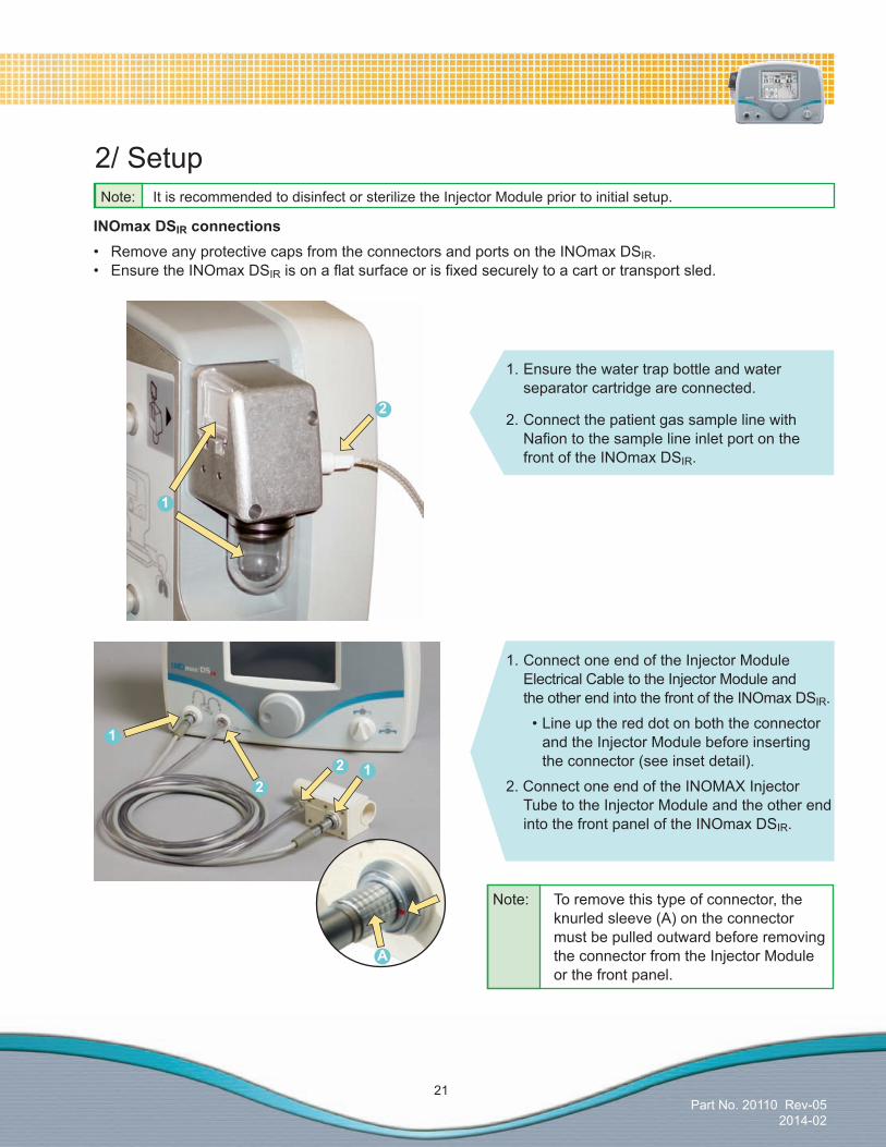
Note: To remove this type of connector, the knurled sleeve (A) on the connector must be pulled outward before removing the connector from the Injector Module or the front panel.
Note: It is recommended to disinfect or sterilize the Injector Module prior to initial setup.
INOmaxDSIR connections• RemoveanyprotectivecapsfromtheconnectorsandportsontheINOmaxDSIR. • EnsuretheINOmaxDSIRisonaflatsurfaceorisfixedsecurelytoacartortransportsled.
2/ Setup
1. Ensure the water trap bottle and water separator cartridge are connected.
2. Connect the patient gas sample line with Nafiontothesamplelineinletportonthe front of the INOmax DSIR.
1. Connect one end of the Injector Module Electrical Cable to the Injector Module and the other end into the front of the INOmax DSIR.
•Lineupthereddotonboththeconnector and the Injector Module before inserting the connector (see inset detail).
2. Connect one end of the INOMAX Injector Tube to the Injector Module and the other end into the front panel of the INOmax DSIR.
A
1
212
1
2
Part No. 20110 Rev-052014-02
22
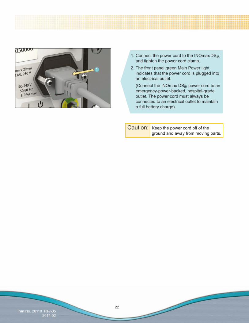
Caution: Keep the power cord off of the ground and away from moving parts.
1. Connect the power cord to the INOmax DSIR and tighten the power cord clamp. 2. The front panel green Main Power light indicates that the power cord is plugged into an electrical outlet. (Connect the INOmax DSIR power cord to an emergency-power-backed, hospital-grade outlet. The power cord must always be connected to an electrical outlet to maintain a full battery charge).
1

Part No. 20003 Rev - 01
(Delivery System)
Part No. 20110 Rev-052014-02
3/ Pre-Use Checkout
Pre-U
se Checkout

(Delivery System)
Part No. 20110 Rev-052014-02
3/ Pre-Use Checkout
Pre
-Use
Che
ckou
t

Part No. 20110 Rev-052014-02
23
WARNING: •AnewINOMAXcylinderandregulatormustbepurgedbeforeusetoensurethepatientdoesnotreceivegreaterthan1.0ppmofNO2.
•LossofcommunicationbetweentheINOmax DSIRandtheINOMAXcylinderformorethanonehourwillresultininterruptionofINOMAXdelivery.
3/ Pre-Use Checkout
The Pre-Use procedures consist of the following tests which must be done before delivering INOMAX to a patient:
Caution: When using the Transport Regulator/Cap Assembly (PN 10022, CGA or 10041, ISO) ensure the cap is fully seated and in place on the INOmeter and the infrared cable is connected and latched to the infrared connector port on the back of the INOmax DSIR (see Figure 4-15, Section 4/Patient Application).
Caution: High frequency and/or high intensity light emission, in the area of the INOmeter, may interfere with communication between the INOmax DSIR and the INOmeter on the INOMAX cylinder (see page 11 and 12).
Note: •FortheCGA-typeINOMAXregulatorconnector, ensure the white plastic tip is not chipped or cracked. Remove and replace as necessary. (see Replacing the tip on the INOMAX regulator, Page 118).
•FortheISO-typeregulatorconnector,check that the O-ring is present and is not damaged (see Replacing the tip on the INOMAX regulator, Page 119).
1. Load two INOMAX gas cylinders onto cart and check for correct product identity labels, cylinder concentration (800 or 400 ppm) and expiration date.
Ensure one INOMAX gas cylinder has adequate gas supply, > 14 bar (200 psig) and one cylinder is full.
2. Connect one of the high pressure regulators to an INOMAX cylinder and hand tighten the fittingtotheINOMAXcylinder.

Part No. 20110 Rev-052014-02
24
Self-TestScreenAn INOmax DSIR splash screen will appear once the device is turned ON followed by an Ikaria test screen(confirmthatthespeakersounds).Thiswillbe followed by the Main Screen.
Note: Do not attempt to connect the Transport Regulator Cap Assembly electrical plug to the INOblender outlet port. This will damage the electrical pins on the connector plug.
Initial ConnectionsConnect the INOmax DSIR as described in Section 2/ Setup and check the cables and hoses for signs of wear or damage.1. Connect the INOMAX regulator hose to
one of the INOMAX inlets (see page 30).2. If using the INOblender with the
INOmax DSIR, connect the INOblender inlet hose (see 2a) to the INOmax DSIR blender outlet (see 2b) and slide the Quick-Connect cover into place (see 2c).
3. Connect oxygen supply (wall source or cylinder oxygen, see 3a) hose to O2 inlet fittingonbackofINOblender(see3b).
Note: 3.4 bar (50 psig, nominal)4. Ensure water trap bottle and water
separator cartridge are in place.5. Connect the Infrared cable from the
INOmax DSIR cart or Transport Regulator/Cap Assembly (PN 10022, CGA or 10041, ISO) to the back of the INOmax DSIR (see Figure 4-15, Section 4/Patient Application).
6. Turn the INOmax DSIR ON.
15
4
2a6
2b
2c
3a
3b
5

Part No. 20110 Rev-052014-02
25
MainScreen
Note: When using the Transport Regulator/Cap Assembly (PN 10022, CGA or 10041, ISO) only one cylinder will be displayed.
When an INOMAX cylinder valve is opened, the cylinder handle graphic will turn green representing an open INOMAX cylinder valve.
The cylinder graphics will appear on the Main Screen in relation to their position on the cart when the user is facing the INOmax DSIR.
Cylinder graphics are not visible and the dose control button will remain inactive until the INOmax DSIR recognizes an INOMAX cylinder.
HighPressureLeakTest 1. Make sure INOblender and backup NO
delivery are OFF.2. Open and then close the cylinder valve.3. Check for adequate cylinder pressure.4. Monitor pressure gauge for 30 seconds
for any signs of pressure decrease. If no pressure decrease is observed, high pressure leak test successful, proceed to Low Range Calibration.
5. If observed pressure decrease continues, see Section 8/ Maintenance; Cylinder Leak Check.

Part No. 20110 Rev-052014-02
26
Low-RangeCalibration
Perform low-range calibration prior to initiation on a patient (see Section 7/ Calibration for procedure).1. Access the menu screen (second menu layer).
2.Pressthe“LowCal”button.
3. Initiate the low-range calibration.
4. When the low-range calibration is successful, the graph bars will turn green and a single tone will be heard. Press the menu button twice to return to the Main Screen.
Note: The low calibration does not require calibration gases.
2
4
3
1
Part No. 20110 Rev-052014-02
27
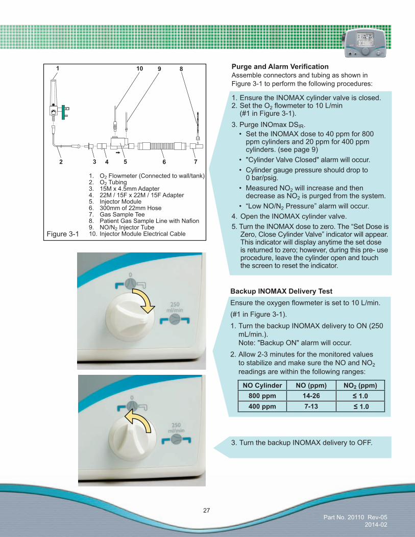
PurgeandAlarmVerification Assemble connectors and tubing as shown in Figure 3-1 to perform the following procedures:
Figure 3-1
1. Ensure the INOMAX cylinder valve is closed.2. Set the O2flowmeterto10L/min (#1 in Figure 3-1).3. Purge INOmax DSIR.•SettheINOMAXdoseto40ppmfor800
ppm cylinders and 20 ppm for 400 ppm cylinders. (see page 9)
• "CylinderValveClosed"alarmwilloccur.• Cylindergaugepressureshoulddropto
0 bar/psig.• MeasuredNO2 will increase and then
decrease as NO2 is purged from the system.• “LowNO/N2 Pressure” alarm will occur.
4. Open the INOMAX cylinder valve.5.TurntheINOMAXdosetozero.The“SetDoseis
Zero, Close Cylinder Valve” indicator will appear. This indicator will display anytime the set dose is returned to zero; however, during this pre- use procedure, leave the cylinder open and touch the screen to reset the indicator.
BackupINOMAXDeliveryTestEnsuretheoxygenflowmeterissetto10L/min.(#1 in Figure 3-1).1. Turn the backup INOMAX delivery to ON (250
mL/min.). Note: "Backup ON" alarm will occur.
2. Allow 2-3 minutes for the monitored values to stabilize and make sure the NO and NO2 readings are within the following ranges:
3. Turn the backup INOMAX delivery to OFF.
1. O2 Flowmeter (Connected to wall/tank)2. O2 Tubing3. 15M x 4.5mm Adapter4. 22M / 15F x 22M / 15F Adapter5. Injector Module6. 300mm of 22mm Hose7. Gas Sample Tee8. PatientGasSampleLinewithNafion9. NO/N2 Injector Tube10. Injector Module Electrical Cable
3
1 10 9 8
2 54 76
NOCylinder NO(ppm) NO2(ppm)800 ppm 14-26 ≤1.0400 ppm 7-13 ≤1.0
Part No. 20110 Rev-052014-02
28
TheINOmaxDSIRisnowreadytoconnecttothepatient.ProceedtoPatientApplication(section4).
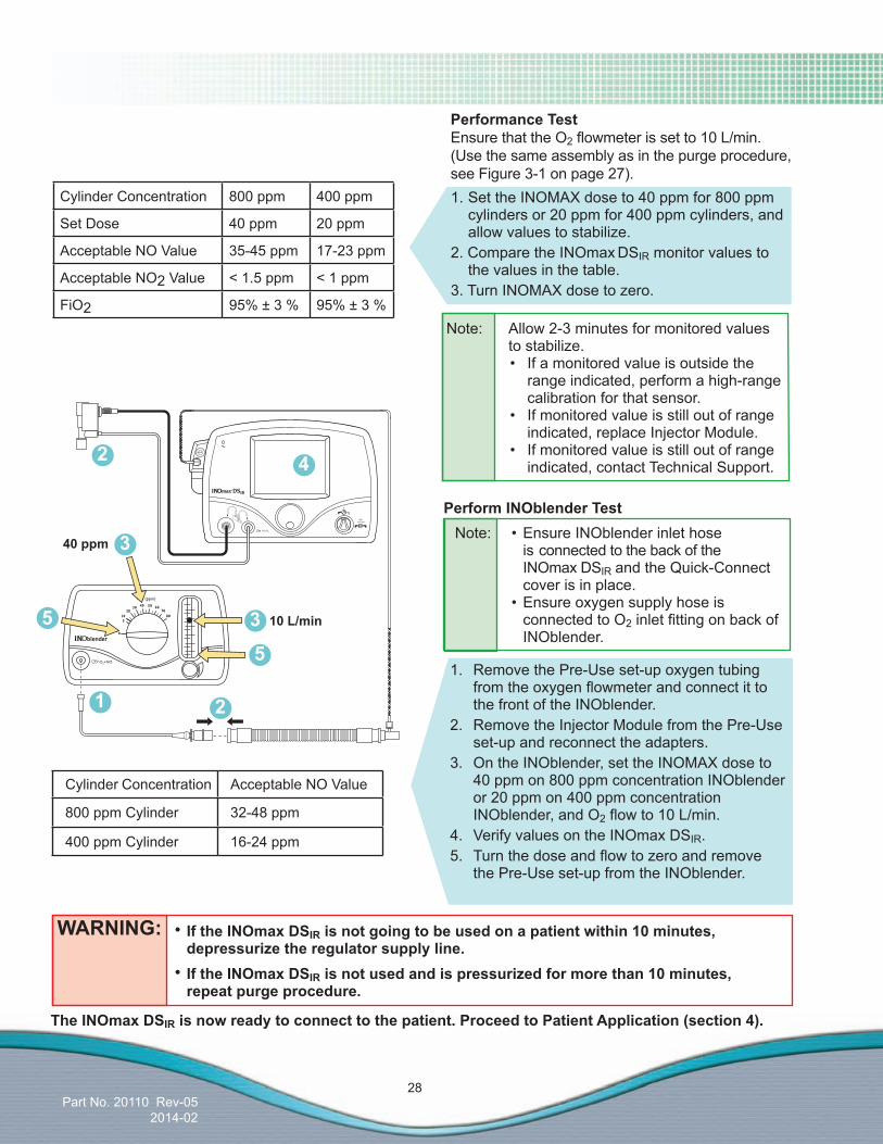
1. Set the INOMAX dose to 40 ppm for 800 ppm cylinders or 20 ppm for 400 ppm cylinders, and allow values to stabilize.
2. Compare the INOmax DSIR monitor values to the values in the table.
3. Turn INOMAX dose to zero.
PerformanceTestEnsure that the O2flowmeterissetto10L/min. (Use the same assembly as in the purge procedure, see Figure 3-1 on page 27).
Note: Allow 2-3 minutes for monitored values to stabilize.• Ifamonitoredvalueisoutsidethe
range indicated, perform a high-range calibration for that sensor.
• Ifmonitoredvalueisstilloutofrangeindicated, replace Injector Module.
• Ifmonitoredvalueisstilloutofrangeindicated, contact Technical Support.
10L/min
Cylinder Concentration Acceptable NO Value
800 ppm Cylinder 32-48 ppm
400 ppm Cylinder 16-24 ppm
Cylinder Concentration 800 ppm 400 ppm
Set Dose 40 ppm 20 ppm
Acceptable NO Value 35-45 ppm 17-23 ppm
Acceptable NO2 Value < 1.5 ppm < 1 ppm
FiO2 95% ± 3 % 95% ± 3 %
WARNING: • IftheINOmaxDSIRisnotgoingtobeusedonapatientwithin10minutes,depressurize the regulator supply line.
• IftheINOmaxDSIRisnotusedandispressurizedformorethan10minutes, repeat purge procedure.
4
1
2
3
5
5
2
3
40 ppm
1. Remove the Pre-Use set-up oxygen tubing fromtheoxygenflowmeterandconnectittothe front of the INOblender.
2. Remove the Injector Module from the Pre-Use set-up and reconnect the adapters.
3. On the INOblender, set the INOMAX dose to 40 ppm on 800 ppm concentration INOblender or 20 ppm on 400 ppm concentration INOblender, and O2flowto10L/min.
4. Verify values on the INOmax DSIR.5. Turnthedoseandflowtozeroandremove
the Pre-Use set-up from the INOblender.
Note: •EnsureINOblenderinlethoseis connected to the back of the INOmax DSIR and the Quick-Connect cover is in place.
•Ensureoxygensupplyhoseisconnected to O2inletfittingonbackofINOblender.
PerformINOblenderTest
Part No. 20110 Rev-052014-02
29
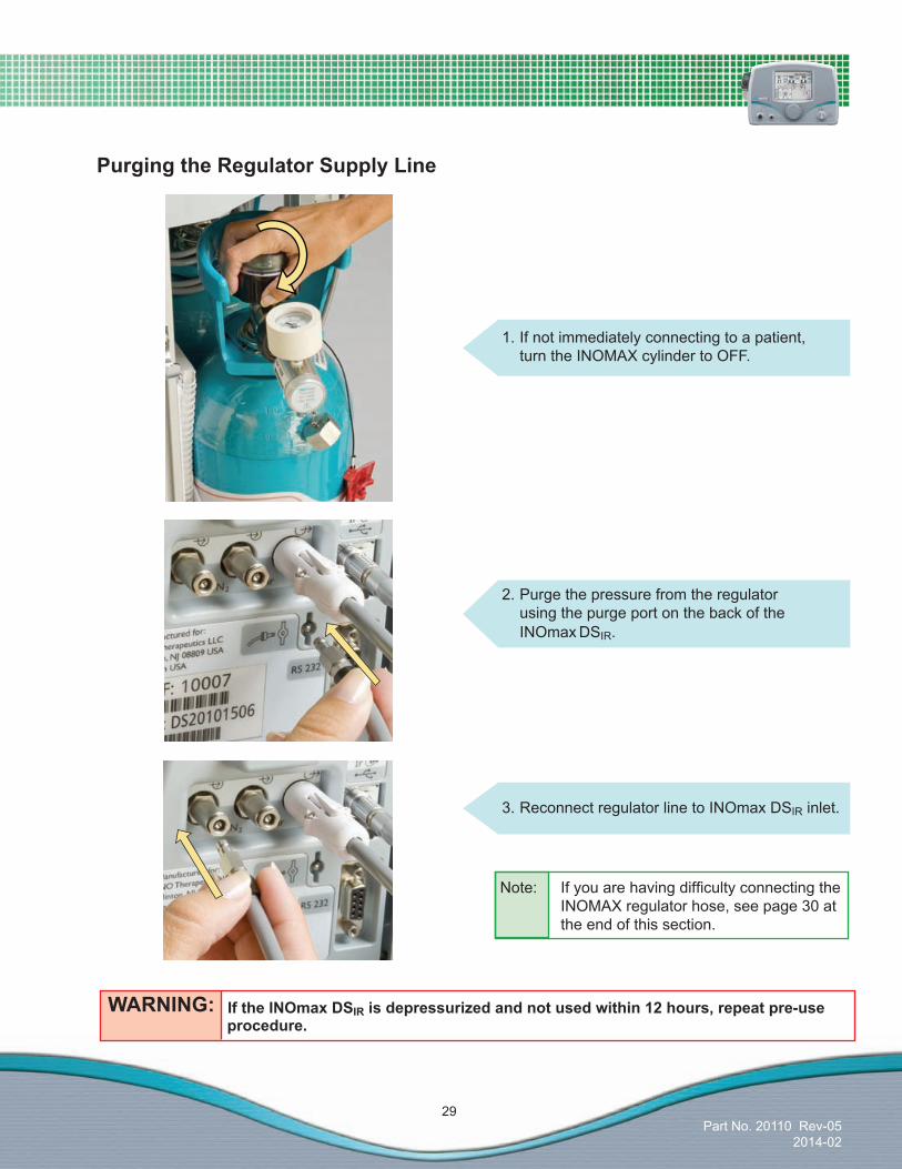
2. Purge the pressure from the regulator using the purge port on the back of the INOmax DSIR.
PurgingtheRegulatorSupplyLine
1. If not immediately connecting to a patient, turn the INOMAX cylinder to OFF.
3. Reconnect regulator line to INOmax DSIR inlet.
WARNING: IftheINOmaxDSIRisdepressurizedandnotusedwithin12hours,repeatpre-use procedure.
Note: IfyouarehavingdifficultyconnectingtheINOMAX regulator hose, see page 30 at the end of this section.

Part No. 20110 Rev-052014-02
30
ProperuseoftheINOMAXinletconnectorsisessentialforsafeandeffectivedeliveryofINOMAX.Followthestepsbelowtoensuretheregulatorhoseisattachedcorrectly.
1. Visually inspect the two inlet connectors and the outlet connector for signs of wear or damage.
2. Prior to connecting a regulator hose, ensure the inlet connectors on the INOmax DSIR unit have the knurled sleeve set in the back position (toward the INOmax DSIR unit, see Figure 3-2). Should the sleeve be in the forward position, the inlet valve will be open and the INOMAX regulator hose will not securely connect to the inlet (see Figure 3-3).
3. Insert the connector from the regulator hose into the gas inlet. Ensure the knurled sleeve moves and clicks into the forward position, locking the connector in place.
4. To disconnect the INOmax DSIR regulator hose, push the knurled sleeve toward the back of the INOmax DSIR unit until the hose disengages.
Figure 3-2 INOMAX gas inlet with the knurled sleeve in the back position.
Ready for use
Figure 3-3INOMAX gas inlet shown with the knurled sleeve in the forward position. Reset prior to use
UsingtheINOMAXGasInletConnector
Part No. 20003 Rev - 01
(Delivery System)
Part No. 20110 Rev-052014-02
4/ Patient Application
Patient
Application

(Delivery System)
Part No. 20110 Rev-052014-02
4/ Patient Application
Pat
ient
App
licat
ion

Part No. 20110 Rev-052014-02
31
Caution:• Usedistilledwaterinthehumidifiertoprevent
the formation of bases or acids.
• NotetheairflowdirectionarrowontheInjectorModule. Flow out of the ventilator must pass through the Injector Module in the direction of the arrow on the module.
• Insert the Injector Module on the dry side of thebreathingcircuitpriortothehumidifier.(Thiswillensurecorrectflowmeasurement).
• Toconditionventilatorflowandensureflowmeasurements are accurate, connect the InjectorModuletothehumidifierchamber,then connect to the ventilator inspiratory port using breathing circuit tubing. This can also be done by placing a breathing circuit filterbetweentheInjectorModuleandtheventilator.
• Infrared, high frequency and/or high intensity light emission, in the area of the INOmeter, may interfere with communication between the INOmax DSIR and the INOmeter on the INOMAX cylinder (see pages 11 and 12).
4/ Patient Application WARNING:• Theuseofdeviceswhichradiatehigh-intensityelectricalfieldsmayaffecttheoperationoftheINOmaxDSIR. Constant surveillanceofallmonitoringandlife-supportequipmentismandatorywheneverinterferingdevicesareinoperationonornear a patient.
• SettheINOmaxDSIR alarm thresholds for the current patient conditions to monitor anyinadvertentchangesintreatment.Foralarminformation,seeSection5/Alarms.
• IftheINOmaxDSIR is not going to be usedonapatientwithin10minutes,depressurize the regulator supply line.
• IftheINOmaxDSIR is not used and is pressurizedformorethan10minutes, repeat purge procedure.
• IftheINOmaxDSIR is depressurized and notusedwithin12hours,repeatpre-useprocedure.
• Becertainallcablesandhosesarepositionedtohelppreventdamagingoroccluding them.
• TheINOmaxDSIR subtracts gas from the breathingcircuitviathegassamplingsystemat230mLperminute;thiscanaffectthesensitivityofaflowtriggeredsynchronized breath mode of some ventilators.ThetriggersensitivityoftheventilatorshouldbecheckedafterconnectingtheINOmaxDSIR to the breathing circuit.
• Theuseofpediatricandneonatalventilatorsettings with adult size breathing circuits canresultinhighlevelsofNO2. Always use the size of breathing circuit that is appropriate for the patient.
WARNING:• Useonly"latex-free"breathingcircuitsandventilatorswhenusingtheINOmaxDSIR.
• Thehumidifierchambervolumeshouldnotbemorethan480mLtopreventelevatedNO2values.
• Patientdisconnectandhighpressurealarmsarerequiredfortheventilator.

Part No. 20110 Rev-052014-02
32
Complete the Setup and Pre-use procedures as described in the previous sections before connecting the INOmax DSIR into the patient’s ventilator breathing circuit. (See the ventilator manual for its setup and operation)
Connectiontotheventilatorbreathingcircuit(Connect the INOmax DSIR into the breathing circuit as shown in the appropriate connection diagrams later in this section, page 58)
1. Insert the Injector Module on the dry side of the breathingcircuitpriortothehumidifier(thiswill ensurecorrectflowmeasurement;seeFigure 4-0 and 4-1 for connection sizes).
2. The distance between the Injector Module and the sample tee must be greater than 24” to ensure proper gas mixing.
3. Make sure the port in the sample tee is pointing upward(thishelpstoavoidfluidaccumulationin the sample line).
4. The distance between the sample tee and the patient wye should be between 150 to 300 mm (6-12 inches) long. Important: This will minimize the sampling of mixed inspired / expired concentrations and ensure correct patient NO/NO2 measurement.
5. Set the INOMAX dose to be delivered to the patient (select,rotate,confirm).
Caution: The gas sensors in the INOmax DSIR monitoring system require humidity in the sample gas to function correctly over the long term. Using the INOmax DSIR without water in the humidifierwillshortenthelifeofthe gas sensors.
BeforeOperation
a. Injector Moduleb. 22F inletc. 22M / 15F outletFigure 4-1
Note: Connections to various ventilators as well as their corresponding disposable circuits, are unique to each manufacturer.
Figure 4-0
6. Set the appropriate alarm settings on the INOmax DSIR and breathing device.
After connecting the INOmax DSIR to the breathing circuit, the trigger sensitivity may need to be adjusted, due to the removal of gases by the sample system.
1
23
b
a
c
Part No. 20110 Rev-052014-02
33
Caution:
WARNING:
INOmeter Operation• TheINOmeterreplacesthestandardrubberizedcylindervalvehandleontheINOMAXcylindersand
is used to open and close the cylinder valve. The INOmeter is a time-metric device which records the amount of time the INOMAX cylinder valve is opened.
• TheINOmeterisdesignedforusewithINOMAXcylindersandwiththeINOvent,INOmaxDSandINOmax DSIR delivery systems.
• WhenusedwithINOmaxDSIR, two-way infrared (IR) communication occurs between the INOmax DSIR and the INOmeter. The INOmeter communicates the INOMAX cylinder concentration and the expiration date to the INOmax DSIR.PatientID(whenconfirmed)anddoseinformationarecommunicated from the INOmax DSIR to the INOmeter.
LossofcommunicationbetweentheINOmaxDSIRandtheINOmeterformorethanonehourwillresultininterruptionofINOMAXdelivery.
• Nothing should be placed between the INOmeter and the cart to which it is attached.• High frequency and/or high intensity light emission in the area of the INOmeter, may
interfere with communication between the INOmax DSIR and the INOmeter on the INOMAX cylinder.
• AstrongmagneticfieldcouldaffecttheabilityoftheINOmetertodetectifthecylindervalveis opened or closed. This may affect the ability of the INOmax DSIR to detect the position (open or closed) of the cylinder valve.
• Removal of the INOmeter from the cylinder must be performed by authorized personnel. Do not dispose of INOmeter.
• INOmeter battery replacement is only to be performed by authorized personnel.

Part No. 20110 Rev-052014-02
34
2. The lock is secured to the cylinder by a lanyard (see Figure 4-3).
Note: •TheINOmeterisusedtoopenandclosethecylindervalve. •Counter-clockwiserotationoftheINOmeterwillopenthecylindervalve. •Clockwiserotationwillclosethecylindervalve. •CylindersareshippedwiththeINOmetercoveredinatamper-proofseal. •Avalvelockissecuredtothecylinderbyalanyard. •Thelockmustberemovedtoopenthecylindervalveforuse.
Figure 4-2
Figure 4-3
1. Remove and properly dispose of tamper-proof seal or covering (see Figure 4-2).

Part No. 20110 Rev-052014-02
35
5. When the INOmeter is turned ON (cylinder open) the display will show a "+" (positive) sign (see Figure 4-6) and alternate between:
a. The event time XX.X in hours since turned ON (8 seconds).
b. The total cumulative time XXX in hours of all the ON events (4 seconds).
c. The display alternates between a and b for the indicated times in parenthesis above.
Figure 4-6 Cylinder Open
Figure 4-7 Cylinder Closed
3. Press lock downward to remove from the INOmeter (see Figure 4-4).
4. The cylinder must be closed to reinsert the lock. Align directly across from the iButton and press upward into socket to attach lock (see Figure 4-5).
Figure 4-5
iButtonCloseCylindervalvetoReplaceLock
Figure 4-4
6. When the INOmeter is turned OFF (cylinder closed) the display will show a "-" (negative) sign (see Figure 4-7) and alternate between:
a. Showing - - - on the display (8 seconds). b. The total cumulative time XXX in hours of
all the ON events (4 seconds). c. The display alternates between a and b
for the indicated times in parenthesis above.
Note: If display is blank, replace cylinder.
Note: If display is blank, replace cylinder.
Note: The INOmeter is used to open and close the cylinder valve. Counter-clockwise rotation of the device serves to open the cylinder valve. Clockwise rotation acts to close the cylinder valve.
Part No. 20110 Rev-052014-02
36
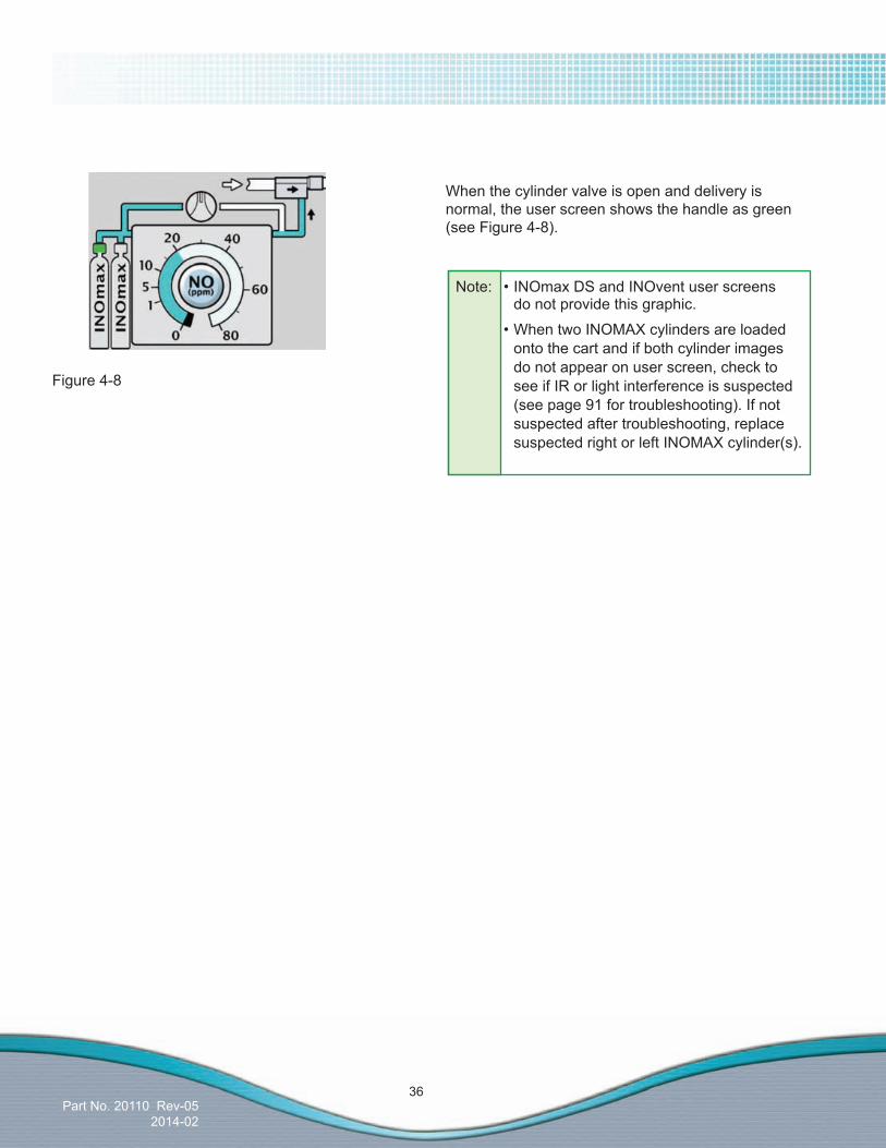
When the cylinder valve is open and delivery is normal, the user screen shows the handle as green (see Figure 4-8).
Figure 4-8
Note: •INOmaxDSandINOventuserscreens do not provide this graphic.
•When two INOMAX cylinders are loaded onto the cart and if both cylinder images do not appear on user screen, check to see if IR or light interference is suspected (see page 91 for troubleshooting). If not suspected after troubleshooting, replace suspected right or left INOMAX cylinder(s).

Part No. 20110 Rev-052014-02
37
Caution:
WARNING:
INOblender Operation Important: Read the INOblender Operation Manual before using the INOblender. Follow instructions
and obey all Warnings and Cautions.
• ThepurgeproceduremustbefollowedtohelpensureNO2 is purged from the system before the manual resuscitator bag is connected to the patient.
• ThemanualbagshouldbesqueezedrepeatedlyduringusetoavoidNO2 from building up in the bag.
• IfthebagisnotsqueezedrepeatedlywhiledeliveringINOMAX,thebagshouldberemovedfromthepatientandthebagpurgeprocedureperformedbefore continuing.
• TheINOblendershouldbeuprightwhensettingtheoxygenflowrateforaccurate setting.
• DonotusepneumaticallypowerednebulizerswiththeINOblender.ThiswillresultinsignificantoverdeliveryofINOMAXinexcessof80ppm(40ppmwitha400ppmcylinder).- TheINOblenderoutletpressurehasbeenvalidatedforuseupto400millibar(5.8psig)pressure.Theamountofback-pressuregeneratedbypneumaticnebulizersissignificantlygreater[1.4to2.0bar(20-30psig)]andwillresultinoverdeliveryofINOMAXinexcessof80ppmwithan800ppmcylinder(40ppmwitha400ppmcylinder).TheuseradjusteddosesettingontheINOblenderwillnotcorrelatewith,orhaveaneffecton,theactualdelivereddose.
- Inaddition,theINOblenderoxygenflowmeterisnotback-pressurecompensatedandwilldisplayalowerthanactualflowratewhenpressureis applied to the outlet.
•Whennotinuse,theoxygenflowmeterandtheINOMAXcylindervalveshouldbeturnedoff.• When the INOblender is used with an oxygen/air blender:- ThespecificationforINOMAXdeliverywhenusingtheINOblenderwith100%oxygenis
+/- 20% of setting or 2 ppm (whichever is greater). The use of 100% oxygen at 3.4 bar (50psig)(nominal)isthelabeledspecificationfortheINOblender.
- A user may determine that some clinical conditions may necessitate the use of an oxygen/air blender with the INOblender to achieve FiO2 levels less than 100%.
- Using oxygen/air mixtures (21% to 95% v/v) will reduce the delivered NO concentration by up to 10% of setting or 1 ppm (whichever is greater) compared to using 100% oxygen alone, resulting in a cumulative error up to +/- 30% of setting or 3 ppm (whichever is greater).
• Refer to the manufacturer's procedures when using the manual resuscitator bag. •Whenfinished,turntheNOcylindervalveOFFandallowtheoxygentoflowuntiltheNOpressuregaugereadszero,thenturntheoxygenflowOFF.
Part No. 20110 Rev-052014-02
38
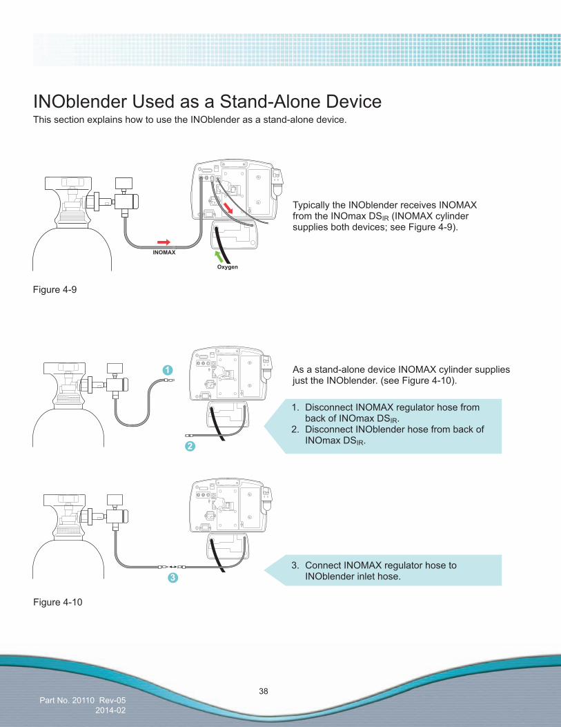
INOblender Used as a Stand-Alone DeviceThis section explains how to use the INOblender as a stand-alone device.
As a stand-alone device INOMAX cylinder supplies just the INOblender. (see Figure 4-10).
Figure 4-9
Figure 4-10
1. Disconnect INOMAX regulator hose from back of INOmax DSIR.2. Disconnect INOblender hose from back of INOmax DSIR.
3. Connect INOMAX regulator hose to INOblender inlet hose.
Typically the INOblender receives INOMAX from the INOmax DSIR (INOMAX cylinder supplies both devices; see Figure 4-9).
1
2
3

Part No. 20110 Rev-052014-02
39
INOblender use with the NeoPuff
1. Oxygen Source2. Neopuff3. T-Piece Circuit (with Duckbill Port)4. Patient Connection5. Temperature Probe
6. HumidifiedResuscitationSystemCircuit7. Humidifier8. Oxygen Tubing9. INOblender10. INOMAX Inlet
7 6
32
4
45
9
8
10
1
Part No. 20110 Rev-052014-02
40
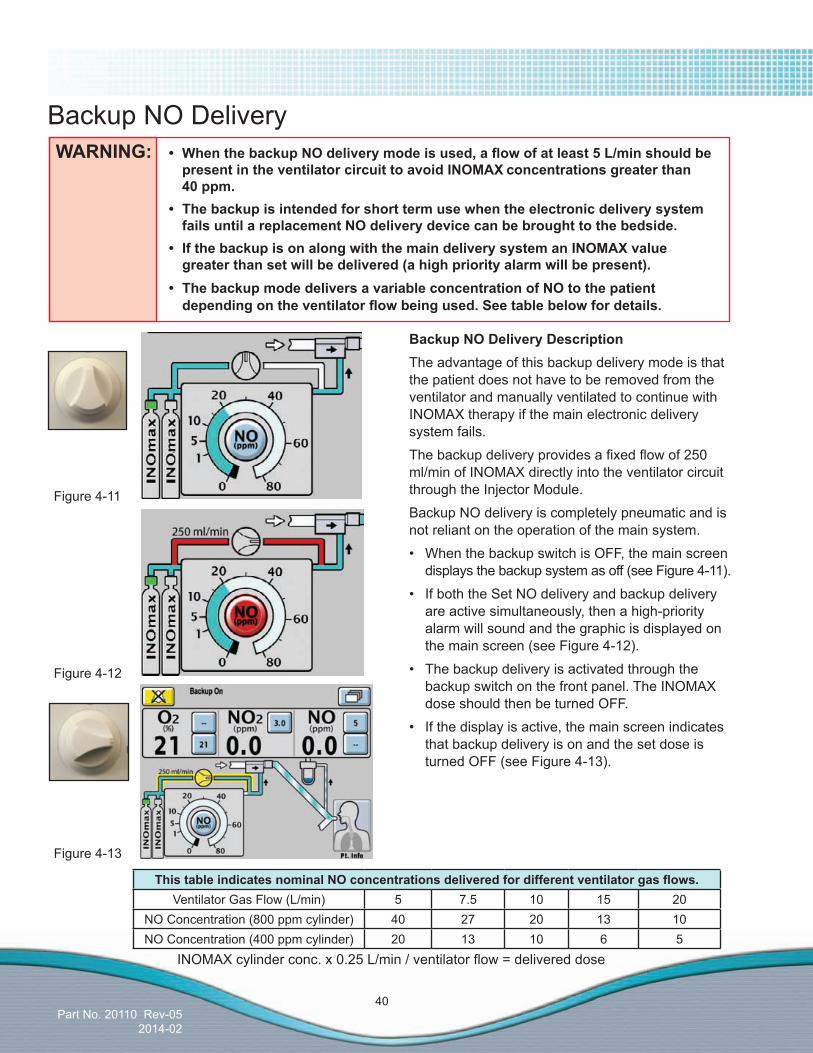
WARNING: • WhenthebackupNOdeliverymodeisused,aflowofatleast5L/minshouldbe presentintheventilatorcircuittoavoidINOMAXconcentrationsgreaterthan 40 ppm. • Thebackupisintendedforshorttermusewhentheelectronicdeliverysystem failsuntilareplacementNOdeliverydevicecanbebroughttothebedside. • IfthebackupisonalongwiththemaindeliverysystemanINOMAXvalue greaterthansetwillbedelivered(ahighpriorityalarmwillbepresent). • ThebackupmodedeliversavariableconcentrationofNOtothepatient dependingontheventilatorflowbeingused.Seetablebelowfordetails.
Backup NO Delivery
Figure 4-11
Figure 4-12
Figure 4-13
BackupNODeliveryDescriptionThe advantage of this backup delivery mode is that the patient does not have to be removed from the ventilator and manually ventilated to continue with INOMAX therapy if the main electronic delivery system fails.
Thebackupdeliveryprovidesafixedflowof250ml/min of INOMAX directly into the ventilator circuit through the Injector Module.
Backup NO delivery is completely pneumatic and is not reliant on the operation of the main system.
• WhenthebackupswitchisOFF,themainscreen displays the backup system as off (see Figure 4-11).
• IfboththeSetNOdeliveryandbackupdelivery are active simultaneously, then a high-priority alarm will sound and the graphic is displayed on the main screen (see Figure 4-12).
• Thebackupdeliveryisactivatedthroughthe backup switch on the front panel. The INOMAX dose should then be turned OFF.
• Ifthedisplayisactive,themainscreenindicates that backup delivery is on and the set dose is turned OFF (see Figure 4-13).
ThistableindicatesnominalNOconcentrationsdeliveredfordifferentventilatorgasflows.Ventilator Gas Flow (L/min) 5 7.5 10 15 20
NO Concentration (800 ppm cylinder) 40 27 20 13 10NO Concentration (400 ppm cylinder) 20 13 10 6 5
INOMAXcylinderconc.x0.25L/min/ventilatorflow=delivereddose
Part No. 20110 Rev-052014-02
41
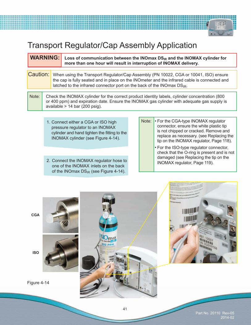
WARNING: LossofcommunicationbetweentheINOmaxDSIRandtheINOMAXcylinderfor morethanonehourwillresultininterruptionofINOMAXdelivery.
Transport Regulator/Cap Assembly Application
Caution: When using the Transport Regulator/Cap Assembly (PN 10022, CGA or 10041, ISO) ensure the cap is fully seated and in place on the INOmeter and the infrared cable is connected and latched to the infrared connector port on the back of the INOmax DSIR.
Note: Check the INOMAX cylinder for the correct product identity labels, cylinder concentration (800 or 400 ppm) and expiration date. Ensure the INOMAX gas cylinder with adequate gas supply is available > 14 bar (200 psig).
1. Connect either a CGA or ISO high pressure regulator to an INOMAX cylinderandhandtightenthefittingtotheINOMAX cylinder (see Figure 4-14).
2. Connect the INOMAX regulator hose to one of the INOMAX inlets on the back of the INOmax DSIR (see Figure 4-14).
Figure 4-14
Note: •FortheCGA-typeINOMAXregulatorconnector, ensure the white plastic tip is not chipped or cracked. Remove and replace as necessary. (see Replacing the tip on the INOMAX regulator, Page 118).
•FortheISO-typeregulatorconnector,check that the O-ring is present and is not damaged (see Replacing the tip on the INOMAX regulator, Page 119).
CGA
ISO
Part No. 20110 Rev-052014-02
42
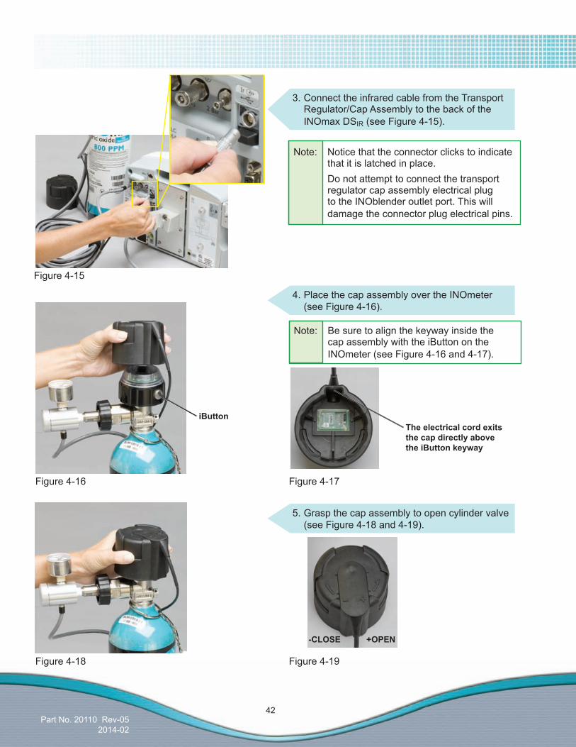
3. Connect the infrared cable from the Transport Regulator/Cap Assembly to the back of the INOmax DSIR (see Figure 4-15).
Figure 4-15
Figure 4-16
4. Place the cap assembly over the INOmeter (see Figure 4-16).
Figure 4-17
Figure 4-18 Figure 4-19
iButtonTheelectricalcordexitsthecapdirectlyabovethe iButton keyway
-CLOSE +OPEN
Note: Be sure to align the keyway inside the cap assembly with the iButton on the INOmeter (see Figure 4-16 and 4-17).
5. Grasp the cap assembly to open cylinder valve (see Figure 4-18 and 4-19).
Note: Notice that the connector clicks to indicate that it is latched in place. Do not attempt to connect the transport regulator cap assembly electrical plug to the INOblender outlet port. This will damage the connector plug electrical pins.

Part No. 20110 Rev-052014-02
43
Final Set-up DiagramThe following diagram (see Figure 4-20) illustrates all of the components connected.
Figure 4-20
Figure 4-21
Note: •Cylindergraphicsarenotvisibleandthedose control button will remain inactive until the INOmax DSIR recognizes an INOMAX cylinder.
•Onlyonecylinderwillbedisplayedwhenusing the Transport Regulator/Cap Assembly (see Figure 4-21).
Additional Information
Communication will take place between the INOmax DSIR and the INOmeter after the boot up phase of the INOmax DSIR is complete.
Part No. 20110 Rev-052014-02
44
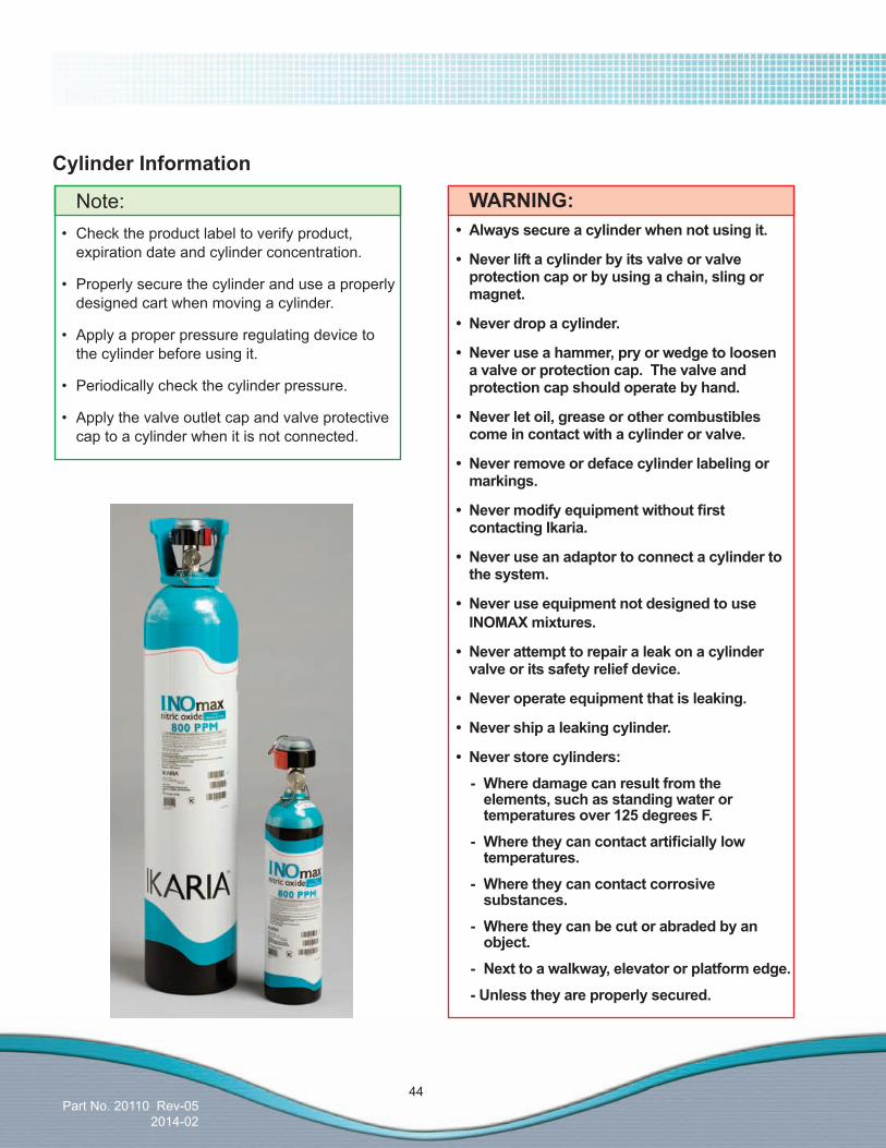
Cylinder Information
WARNING:• Always secure a cylinder when not using it.
• Neverliftacylinderbyitsvalveorvalveprotectioncaporbyusingachain,slingormagnet.
• Neverdropacylinder.
• Neveruseahammer,pryorwedgetoloosenavalveorprotectioncap.Thevalveandprotection cap should operate by hand.
• Neverletoil,greaseorothercombustiblescomeincontactwithacylinderorvalve.
• Neverremoveordefacecylinderlabelingormarkings.
• Nevermodifyequipmentwithoutfirstcontacting Ikaria.
• Neveruseanadaptortoconnectacylindertothe system.
• NeveruseequipmentnotdesignedtouseINOMAX mixtures.
• Neverattempttorepairaleakonacylindervalveoritssafetyreliefdevice.
• Neveroperateequipmentthatisleaking.
• Nevershipaleakingcylinder.
• Neverstorecylinders:
- Where damage can result from the elements,suchasstandingwateror temperaturesover125degreesF.
- Wheretheycancontactartificiallylow temperatures.
- Wheretheycancontactcorrosive substances.
- Where they can be cut or abraded by an object.
- Nexttoawalkway,elevatororplatformedge.
-Unlesstheyareproperlysecured.
Note:• Checktheproductlabeltoverifyproduct,
expiration date and cylinder concentration.
• Properlysecurethecylinderanduseaproperlydesigned cart when moving a cylinder.
• Applyaproperpressureregulatingdevicetothe cylinder before using it.
• Periodicallycheckthecylinderpressure.
• Applythevalveoutletcapandvalveprotectivecap to a cylinder when it is not connected.
Part No. 20110 Rev-052014-02
45
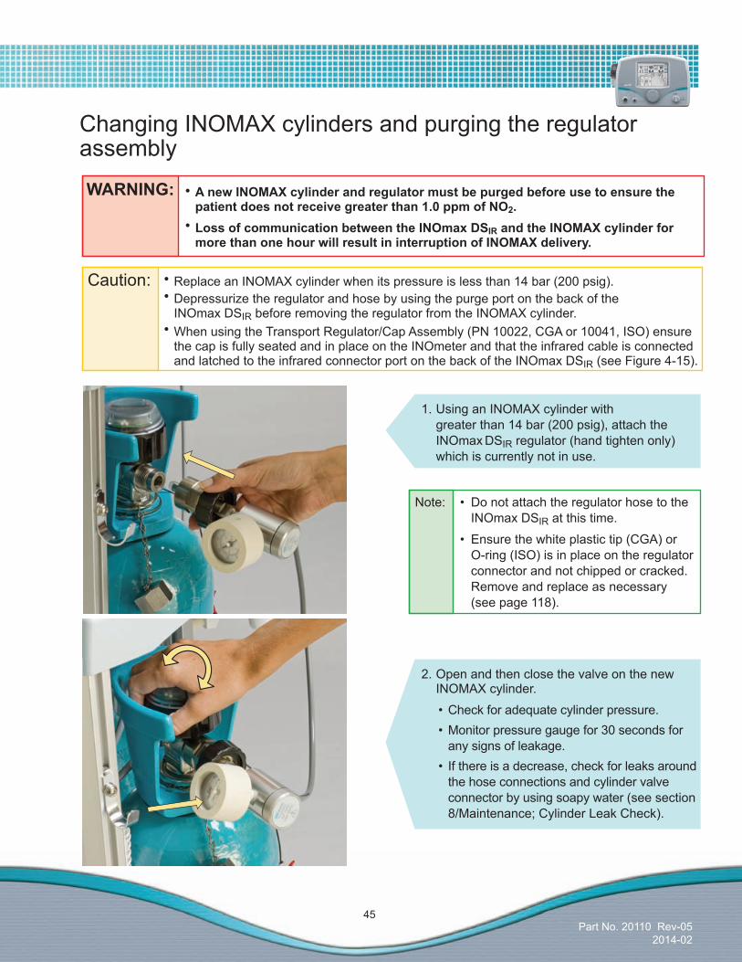
Caution: •Replace an INOMAX cylinder when its pressure is less than 14 bar (200 psig). •Depressurize the regulator and hose by using the purge port on the back of the
INOmax DSIR before removing the regulator from the INOMAX cylinder. •When using the Transport Regulator/Cap Assembly (PN 10022, CGA or 10041, ISO) ensure
the cap is fully seated and in place on the INOmeter and that the infrared cable is connected and latched to the infrared connector port on the back of the INOmax DSIR (see Figure 4-15).
1. Using an INOMAX cylinder with greater than 14 bar (200 psig), attach the INOmax DSIR regulator (hand tighten only) which is currently not in use.
Changing INOMAX cylinders and purging the regulator assembly
2. Open and then close the valve on the new INOMAX cylinder.
•Checkforadequatecylinderpressure.•Monitorpressuregaugefor30secondsfor
any signs of leakage.• Ifthereisadecrease,checkforleaksaround
the hose connections and cylinder valve connector by using soapy water (see section 8/Maintenance; Cylinder Leak Check).
Note: • Donotattachtheregulatorhosetothe INOmax DSIR at this time.
• Ensurethewhiteplastictip(CGA)or O-ring (ISO) is in place on the regulator connector and not chipped or cracked. Remove and replace as necessary (see page 118).
WARNING: •AnewINOMAXcylinderandregulatormustbepurgedbeforeusetoensurethepatientdoesnotreceivegreaterthan1.0ppmofNO2.
•LossofcommunicationbetweentheINOmaxDSIRandtheINOMAXcylinderformorethanonehourwillresultininterruptionofINOMAXdelivery.

Part No. 20110 Rev-052014-02
46
3. Insert the NO/N2quick-connectfittinginto the purge port on the back of the INOmax DSIRandfirmlypushuntilthe regulator pressure gauge reads zero (this purges any NO2 that has accumulated in the hose and regulator).
6. Close the cylinder valve on the empty cylinder and remove the supply line from the back of the INOmax DSIR.
7. Depressurize by using the purge port on the back of the INOmax DSIR and remove the regulator from the empty cylinder.
4. Connect the hose to the back of the INOmax DSIR (NO/N2 inlet). If you are having difficultyconnectingtheINOMAX regulator hose, see page 30.
Note: If using the INOmax DSIR Transport Regulator/Cap Assembly, transfer the cap from the empty INOMAX cylinder to the new INOMAX cylinder at this time (see page 42). "Cylinder Not Detected" alarm may occur.
5. Open the cylinder valve on the new cylinder. Thismayactivatethe“TwoCylindersOpen”alarm until the empty cylinder valve is closed.5
6

Part No. 20110 Rev-052014-02
47
Caution FiO2 less than 21%
0.21
0.21
0.20
0.20
0.19
0.40
0.40
0.39
0.38
0.36
0.60
0.59
0.59
0.57
0.54
0.80
0.79
0.78
0.76
0.72
.21 .40 .60 .80
SetFiO2
5
10/5
20/10
40/20
80/40
1.00
0.99
0.99
0.98
0.95
0.90
ActualFiO2
!
!
!
OxygenDilutionChartFordeliverywith800ppm(whitedosetext)cylinder.Fordeliverywith400ppm(blackdosetext)cylinder. (IllustrativeOnly)
Please note: The calculations on this chart have been determined based on an 800/400 ppm cylinder of INOMAX (nitric oxide) for inhalation.
This chart is representative of a range of doses available on the INOmax DSIR and doses higher than 20 ppm are not the recommended therapeutic dose.
Calculations are considered estimates and may vary under clinical circumstances.
All numbers have been rounded to the nearest hundredth.
INOMAXDose
(ppm
)

Part No. 20110 Rev-052014-02
48
Duration ChartINOMAXCylinderLuxfer10L-SizeForaLuxfer-Size800ppm(whitedosetext)and400ppm(blackdosetext)Cylinder Concentration* (IllustrativeOnly)
This chart is representative of a range of doses available on the INOmax DSIR and doses higher than 20 ppm are not the recommended therapeutic dose.
* All calculations for the table above are based on a full cylinder of 138 bar (2000 psig), 1362 liters Luxfercylinder,andalsoaccountingforcylinderchangeat14bar(200psig).Thefiguresarecalculatedontotalcontinuousflowcylinderconversionfactor(9.9litersperbarand0.68litersperpsi).
INOMAXflow=[DesireddoseXtotalventilatorflow]/[Cylinderconcentration–desireddose]Cylindervolume=CylinderconversionfactorXcylinderpressure(bar/psig)Cylinderduration=Cylindervolume/INOMAXflowrate
Calculations are considered estimates and may vary under clinical circumstances.
For more information, contact Customer Support at the number on the back cover.
FLOW
5L/min 10L/min 20L/min 40L/min
5 27.0 Days 13.5 Days 6.8 Days 3.4 Days
10/5 13.4 Days 6.7 Days 3.4 Days 1.7 Days
20/10 6.6 Days 3.3 Days 1.7 Days 19.9 Hours
40/20 3.2 Days 1.6 Days 19.4 Hours 9.7 Hours
80/40 1.5 Days 18.4 Hours 9.2 Hours 4.6 Hours
INOMAXDose(ppm
)
Part No. 20110 Rev-052014-02
49
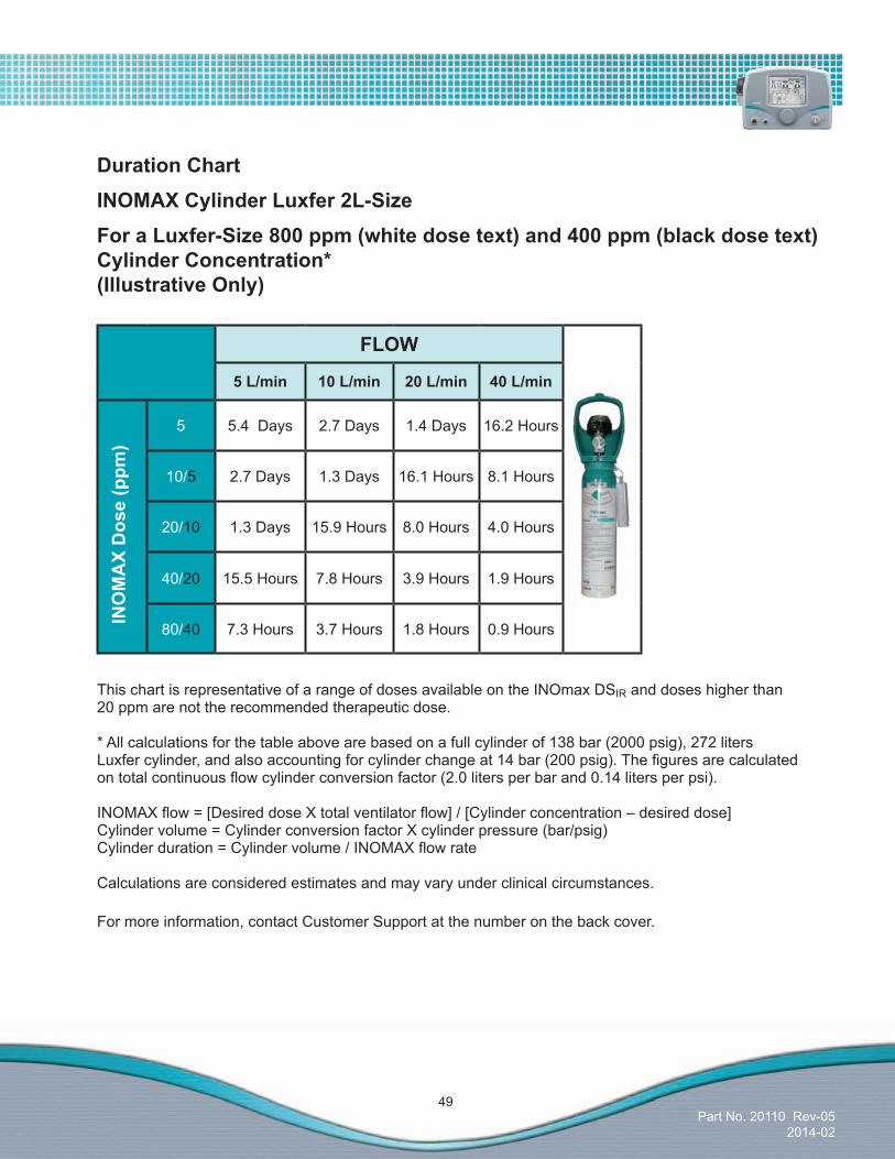
This chart is representative of a range of doses available on the INOmax DSIR and doses higher than 20 ppm are not the recommended therapeutic dose.
* All calculations for the table above are based on a full cylinder of 138 bar (2000 psig), 272 liters Luxfercylinder,andalsoaccountingforcylinderchangeat14bar(200psig).Thefiguresarecalculatedontotalcontinuousflowcylinderconversionfactor(2.0litersperbarand0.14litersperpsi).
INOMAXflow=[DesireddoseXtotalventilatorflow]/[Cylinderconcentration–desireddose]Cylindervolume=CylinderconversionfactorXcylinderpressure(bar/psig)Cylinderduration=Cylindervolume/INOMAXflowrate
Calculations are considered estimates and may vary under clinical circumstances.
For more information, contact Customer Support at the number on the back cover.
FLOW
5L/min 10L/min 20L/min 40L/min
5 5.4 Days 2.7 Days 1.4 Days 16.2 Hours
10/5 2.7 Days 1.3 Days 16.1 Hours 8.1 Hours
20/10 1.3 Days 15.9 Hours 8.0 Hours 4.0 Hours
40/20 15.5 Hours 7.8 Hours 3.9 Hours 1.9 Hours
80/40 7.3 Hours 3.7 Hours 1.8 Hours 0.9 Hours
Duration ChartINOMAXCylinderLuxfer2L-SizeForaLuxfer-Size800ppm(whitedosetext)and400ppm(blackdosetext)Cylinder Concentration* (IllustrativeOnly)
INOMAXDose(ppm
)
Part No. 20110 Rev-052014-02
50
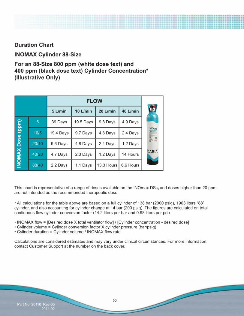
Duration ChartINOMAXCylinder88-SizeForan88-Size800ppm(whitedosetext)and 400ppm(blackdosetext)CylinderConcentration*(IllustrativeOnly)
This chart is representative of a range of doses available on the INOmax DSIR and doses higher than 20 ppm are not intended as the recommended therapeutic dose.
*Allcalculationsforthetableabovearebasedonafullcylinderof138bar(2000psig),1963liters“88”cylinder,andalsoaccountingforcylinderchangeat14bar(200psig).Thefiguresarecalculatedontotalcontinuousflowcylinderconversionfactor(14.2litersperbarand0.98litersperpsi).
•INOMAXflow=[DesireddoseXtotalventilatorflow]/[Cylinderconcentration-desireddose]•Cylindervolume=CylinderconversionfactorXcylinderpressure(bar/psig)•Cylinderduration=Cylindervolume/INOMAXflowrate
Calculations are considered estimates and may vary under clinical circumstances. For more information, contact Customer Support at the number on the back cover.
FLOW
5L/min 10L/min 20L/min 40L/min
5 39 Days 19.5 Days 9.8 Days 4.9 Days
10/5 19.4 Days 9.7 Days 4.8 Days 2.4 Days
20/10 9.6 Days 4.8 Days 2.4 Days 1.2 Days
40/20 4.7 Days 2.3 Days 1.2 Days 14 Hours
80/40 2.2 Days 1.1 Days 13.3 Hours 6.6 HoursINOMAXDose(ppm
)
Part No. 20110 Rev-052014-02
51
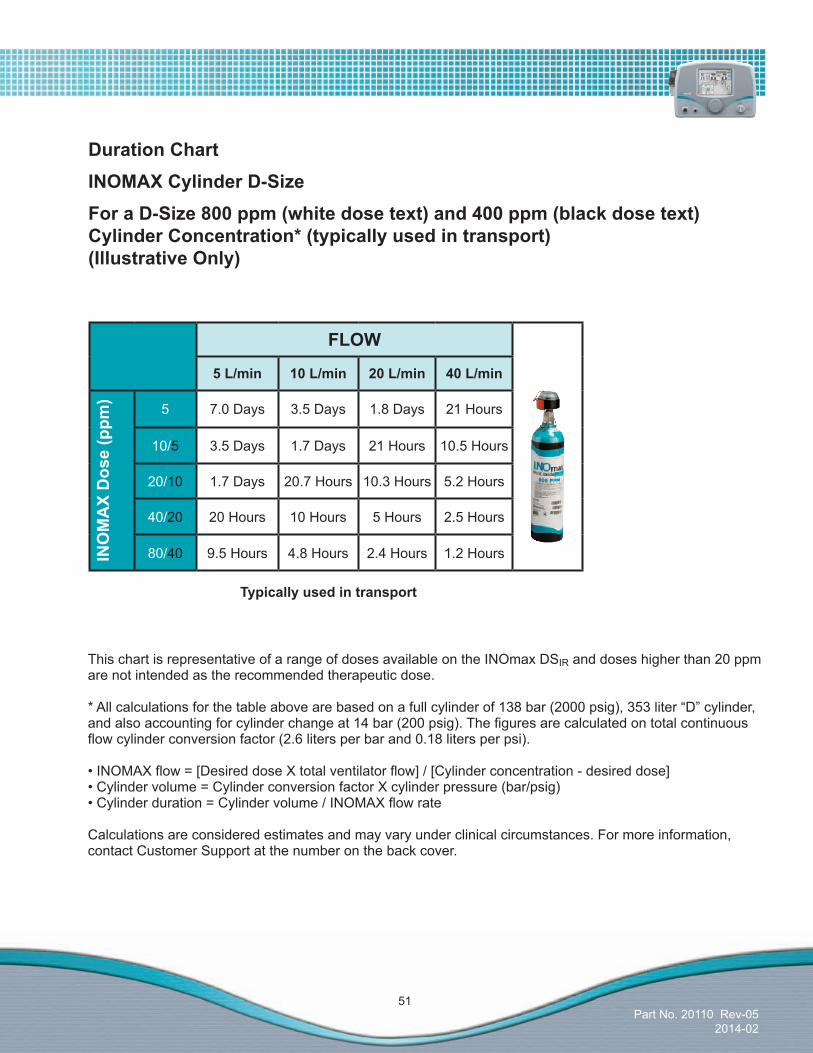
Duration ChartINOMAXCylinderD-SizeForaD-Size800ppm(whitedosetext)and400ppm(blackdosetext) CylinderConcentration*(typicallyusedintransport) (IllustrativeOnly)
Typicallyusedintransport
This chart is representative of a range of doses available on the INOmax DSIR and doses higher than 20 ppm are not intended as the recommended therapeutic dose.
*Allcalculationsforthetableabovearebasedonafullcylinderof138bar(2000psig),353liter“D”cylinder,andalsoaccountingforcylinderchangeat14bar(200psig).Thefiguresarecalculatedontotalcontinuousflowcylinderconversionfactor(2.6litersperbarand0.18litersperpsi).
•INOMAXflow=[DesireddoseXtotalventilatorflow]/[Cylinderconcentration-desireddose]•Cylindervolume=CylinderconversionfactorXcylinderpressure(bar/psig)•Cylinderduration=Cylindervolume/INOMAXflowrate
Calculations are considered estimates and may vary under clinical circumstances. For more information, contact Customer Support at the number on the back cover.
FLOW
5L/min 10L/min 20L/min 40L/min
5 7.0 Days 3.5 Days 1.8 Days 21 Hours
10/5 3.5 Days 1.7 Days 21 Hours 10.5 Hours
20/10 1.7 Days 20.7 Hours 10.3 Hours 5.2 Hours
40/20 20 Hours 10 Hours 5 Hours 2.5 Hours
80/40 9.5 Hours 4.8 Hours 2.4 Hours 1.2 HoursINOMAXDose(ppm
)

Part No. 20110 Rev-052014-02
52
Note: Monitoringwillbetemporarilyinterruptedwhenthe“WaterBottleFull”messageisindicated.
The water trap bottle on the left side of the system (seeFigure4-22)collectsfluidsseparatedfromthepatient gas sample.
•Emptyandcleanthewatertrapbottlebeforeeach patient use and empty whenever the trap is more than half full.
•Emptythewatertrapbottleroutinely.Allowingitto fillandoverflowmaycausesystemerrors.
•A“WaterBottleFull”messagewillremindyouto emptyandcleanthefluidtrapshoulditbecomefull.
Note: During delivery of INOMAX to a patient
1. The disposable Water Separator Cartridge on the rear of the water trap housing protects the monitoring system from moisture and other contaminants and may need to be replaced occasionally while in use. (Refer to Section 8/ Maintenance).
2. To avoid medications interfering with the gas monitoring system, administer any aerosolized medications distal to the sampling tee (refer to page 54).
ToemptytheWaterTrapBottle:
1. Remove the bottle by pulling it straight down (see Figure 4-22).
2. Discard the contents according to an approvedfluidwastedisposalpolicy.
3. Clean the bottle.
4. Replace the bottle by pushing it up into position.
5. Check for leaks by running the system and occluding the sample line until the sample line occlusion alarm message appears.
EmptyingtheWaterTrapBottle
WARNING: When handling any component of the patient circuit that comes in contact with patient’sfluidswearprotectivesafetyequipment.
Figure 4-22
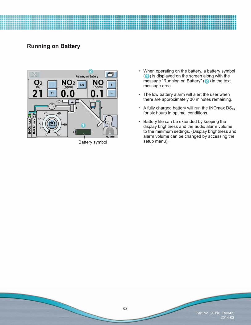
Part No. 20110 Rev-052014-02
53
Battery symbol
1
2 • Whenoperatingonthebattery,abatterysymbol ( ) is displayed on the screen along with the message“RunningonBattery”() in the text message area.
• Thelowbatteryalarmwillalerttheuserwhen there are approximately 30 minutes remaining.
• AfullychargedbatterywillruntheINOmaxDSIR for six hours in optimal conditions.
• Batterylifecanbeextendedbykeepingthe display brightness and the audio alarm volume to the minimum settings. (Display brightness and alarm volume can be changed by accessing the setup menu).
21
Running on Battery

Part No. 20110 Rev-052014-02
54
Location of nebulizer distal from the inspiratory gas sample tee
Disk Filter, 0.5 micron
Note: Thediskfilteristobeusedinconjunctionwith the INOmax DSIR water separator cartridge. Never operate the INOmax DSIR without the water separator cartridge.
•Thisdiskfilterhasbeenvalidated for this purpose.
•Thisdiskfiltermustbereplacedfollowing each treatment period.
•Duringcontinuousmedicationdelivery,frequent disk replacement may be necessary due to the disk becoming saturated with moisture/medication.
•However,frequentdiskreplacementwillreduce the frequency of water separator cartridge replacement during medication delivery.
Figure 4-23
Figure 4-24
InspiredGasSamplingDuringAerosolDelivery
• Place the medication nebulizer downstream of the sample tee on the inspiratory limb to prevent over saturation of the water separator cartridge; contamination of the sample system and avoid a “sampleline/filterblock”alarm (see Figure 4-23).
• Tominimizereplacementofthewaterseparator cartridge during aerosol delivery, a small 0.5 micron hydrophobicdiskfilterwithluerconnectionsmust be placed between the sample line and sample tee (see Figure 4-24).
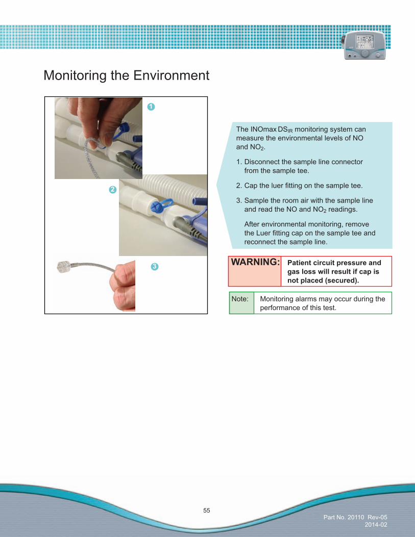
Part No. 20110 Rev-052014-02
55
The INOmax DSIR monitoring system can measure the environmental levels of NO and NO2.
1. Disconnect the sample line connector from the sample tee.
2.Captheluerfittingonthesampletee.
3. Sample the room air with the sample line and read the NO and NO2 readings.
After environmental monitoring, remove theLuerfittingcaponthesampleteeand reconnect the sample line.
WARNING: Patient circuit pressure and gas loss will result if cap is notplaced(secured).
Monitoring the Environment
Note: Monitoring alarms may occur during the performance of this test.
1
2
3

Part No. 20110 Rev-052014-02
56
Thefollowingareinstructionsonhowtousethepatientidentifierscreen:
• Pressingthekeysonthekeyboardallowstheusertoenterasequentialalphanumericidentifier.
• Priortoconfirmingtheidentifier,digitscanbechanged either by pressing the backspace button ( ) or pressing the digit that has been entered and typing over it.
• The“Confirm”button()willilluminatewhensixcharacters have been entered.
After pressing the patient information button, the following screen will appear (see Figure 4-26).
Apatientidentifiercanbeenteredatanytimeduring the treatment of a patient by pressing the patient information button in the right-lower corner of the Main Screen.
Figure 4-25
Entering Patient Information
1
Note: Oncethe“Confirm”buttonhasbeenpressed, theidentifierremainsunchangeableuntil therapy is ended by turning the device to Standby (OFF).
Note:Ifpatientidentifierhasnotbeenentereda“PatientInfo.Incomplete”indicator()will stay illuminated in the text message area of the screen (see Figure 4-25).
Figure 4-26
1
2
3
Note: Anyidentifierenteredwillbelinked with each INOMAX cylinder used during treatment.
ThePatientIdentifierscreen(seeFigure4-26)allowsauniquealphanumericpatientidentifierto be entered that contains six to eight digits (note: spaces will be accepted).
Note: For compliance to European Directive 95/46/EC,donotuseidentifierstraceabletoaspecificpatient.Consultandcomplywith your internal hospital guidelines whenenteringapatientidentifier.
2
3
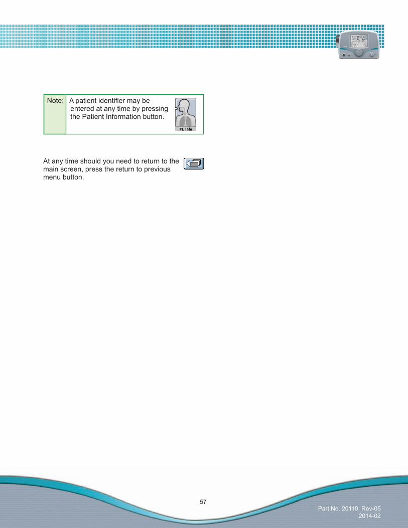
Part No. 20110 Rev-052014-02
57
At any time should you need to return to the main screen, press the return to previous menu button.
Note: Apatientidentifiermaybe entered at any time by pressing the Patient Information button.

Part No. 20110 Rev-052014-02
58
Note:Connections to various ventilators as well as their corresponding disposable circuits, are unique to each manufacturer.
Caution:•NotetheairflowdirectionarrowontheInjector
Module. Flow out of the ventilator must pass through the Injector Module in the direction of the arrow on the module.
•InserttheInjectorModuleonthedrysideofthebreathingcircuitpriortothehumidifier(thiswillensurecorrectflowmeasurement).
•Toconditionventilatorflowandensureflowmeasurements are accurate, connect the InjectorModuletothehumidifierchamberinlet. Then connect to the ventilator inspiratory port using breathing circuit tubing. This can also be done by placing a breathing circuit filterbetweentheInjectorModuleandtheventilator.
•Avoidmedicationswhichinterferewiththegasmonitoring system; administer any aerosolized medications downstream of the sampling tee.
•TheINOmaxDSIR is designed to function in the parameter ranges listed in Section 9/ProductSpecifications.Useoutsideoftheseranges is not recommended.
Connection to Various Breathing Systems
WARNING:•TheINOmaxDSIR subtracts gas from the breathingcircuitviathegassampling systemat230mLperminute;thiscaneffectthesensitivityofaflowtriggeredsynchronized breath mode of some ventilators.ThetriggersensitivityoftheventilatorshouldbecheckedafterconnectingtheINOmaxDSIR to the breathing circuit.
•Thehumidifierchambervolumeshouldnotbemorethan480mLtopreventelevatedNO2values.
•Patientdisconnectandhighpressurealarmsarerequiredfortheventilator.
•TheINOmaxDSIR should not be used with the BiPap Vision sytem or other single-lumen breathing sytems with bidirectional flow,asover-doseofINOMAX(nitricoxide)andinterruptionofdrugdeliverytothe patient may occur.
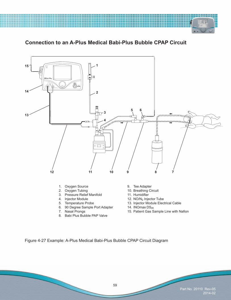
Part No. 20110 Rev-052014-02
59
1. Oxygen Source2. Oxygen Tubing3. Pressure Relief Manifold4. Injector Module5. Temperature Probe6. 90 Degree Sample Port Adapter7. Nasal Prongs8. Babi Plus Bubble PAP Valve
9. Tee Adapter10. Breathing Circuit11. Humidifier12. NO/N2 Injector Tube13. Injector Module Electrical Cable14. INOmax DSIR15.PatientGasSampleLinewithNafion
9 811 710
14
3
4
6
2
5
12
13
115
ConnectiontoanA-PlusMedicalBabi-PlusBubbleCPAPCircuit
Figure 4-27 Example: A-Plus Medical Babi-Plus Bubble CPAP Circuit Diagram

Part No. 20110 Rev-052014-02
60
WARNING: • Thehyperinflationbagwill,undersomeconditions,containNO2inexcessof 1ppm.UseoflargetidalvolumebreathsmayexposethepatientstotheNO2 presentinthebag,forpartofthebreath.Ingeneral,iftheinspiratoryflowrate inducedbythemanualventilationdoesnotexceedthefreshgasflowrate,the patientshouldnotbeexposedtotheconcentrationsofNO2 present in the hyperinflationbag. • AdultandinfanthyperinflationbagsgeneratemoreNO2 when used at lower minuteventilation.Ifuseofthebagisinterrupted(forexampletoadjustthe trachealtube),beforeresumingventilationofthepatient,theusershould squeezethebagseveraltimestoemptyresidualgasfromthebag. • BecauseofthepotentialforinhalationofexcessiveconcentrationsofNO2,and thedifficultyinmonitoringthepeakinhaledNO2concentrations,ventilationwith ahyperinflationbagorselfinflatingbagisintendedonlyforshorttermuse. • ThemonitoringsystemwithintheINOmaxDSIRwillnotdetectgenerationofNO2 withinthehyperinflationbagorself-inflatingbagdevicesandthealarmsfor excessiveNO2cannotwarnofNO2 produced within the manual bag system. • TominimizethedeliveredconcentrationofNO2,thefollowingstepsshouldbe taken for use with the manual resuscitator bags: - Concentrationsgreaterthan20ppmNOshouldnotbeusedbecauseof excessiveNO2 generation. - Usethesmallestbagadequatetodeliverthedesiredtidalvolume. - Inspiratorytubinglengthsgreaterthan1.8meters(72inches)shouldnot be used. - Usethehighestfreshgasflowrate(upto15L/min)thatispractical. - Usethelowestpracticalinspiredoxygenconcentration. - Afterstartingfreshgasflow,squeezethebagseveraltimestoemptyresidual gasinthebagpriortousingthesystemtoventilateapatient.
ConnectiontoBaggingSystemsWhileUsingtheInjectorModule
Caution: New O2tubingmustbeusedeachtimeforoptimalfitonthe4.5mmadapter.
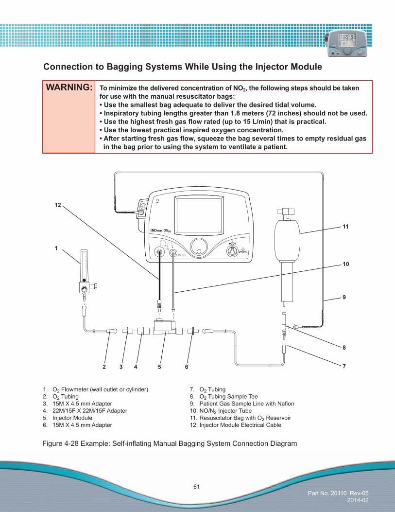
Part No. 20110 Rev-052014-02
61
WARNING: TominimizethedeliveredconcentrationofNO2,thefollowingstepsshouldbetaken for use with the manual resuscitator bags: •Usethesmallestbagadequatetodeliverthedesiredtidalvolume. •Inspiratorytubinglengthsgreaterthan1.8meters(72inches)shouldnotbeused. •Usethehighestfreshgasflowrated(upto15L/min)thatispractical. •Usethelowestpracticalinspiredoxygenconcentration. •Afterstartingfreshgasflow,squeezethebagseveraltimestoemptyresidualgas inthebagpriortousingthesystemtoventilateapatient.
ConnectiontoBaggingSystemsWhileUsingtheInjectorModule
Figure4-28Example:Self-inflatingManualBaggingSystemConnectionDiagram
1. O2 Flowmeter (wall outlet or cylinder)2. O2 Tubing3. 15M X 4.5 mm Adapter4. 22M/15F X 22M/15F Adapter5. Injector Module6. 15M X 4.5 mm Adapter
7. O2 Tubing8. O2 Tubing Sample Tee9. PatientGasSampleLinewithNafion10. NO/N2 Injector Tube11. Resuscitator Bag with O2 Reservoir12. Injector Module Electrical Cable
1
52 643
10
12
11
9
8
7

Part No. 20110 Rev-052014-02
62
Figure4-29Example:HyperinflationManualBaggingSystemDiagram
1. O2 Flowmeter 2. Injector Module Electrical Cable3. NO/N2 Injector Tube4. PatientGasSampleLinewithNafion5. O2 Tubing6. O2 Tubing Sample Tee7. Hyper-InflationBag
8. Pressure Gauge9. 15M X 4.5 mm Adapter10. Injector Module11. 22M/15F X 22M/15F Adapter12. 15M X 4.5 mm Adapter13. O2 Tubing
Testinghasonlybeenconductedusingthefollowinghyperinflationandself-inflatingbagsystems.
• HudsonRCIHyperinflation 1L Adult # 5404
• HudsonRCIHyperinflation 0.5L Neonatal # 5403
• Nellcor-PuritanBennettSelf-inflating 1.76 L Adult # 655005
• Nellcor-PuritanBennettSelf-inflating 0.52 L Infant # 616416
1011 9 81213
7
6
4
2
3
1
5

Part No. 20110 Rev-052014-02
63
(Intentionally left blank)
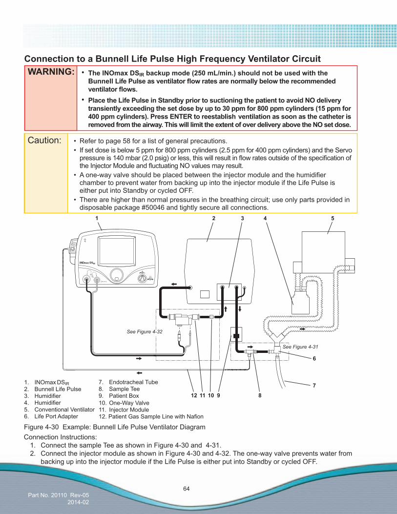
Part No. 20110 Rev-052014-02
64
ConnectiontoaBunnellLifePulseHighFrequencyVentilatorCircuit
Connection Instructions:1. Connect the sample Tee as shown in Figure 4-30 and 4-31.2. Connect the injector module as shown in Figure 4-30 and 4-32. The one-way valve prevents water from backing up into the injector module if the Life Pulse is either put into Standby or cycled OFF.
Figure 4-30 Example: Bunnell Life Pulse Ventilator Diagram
WARNING: • TheINOmaxDSIRbackupmode(250mL/min.)shouldnotbeusedwiththeBunnell LifePulseasventilatorflowratesarenormallybelowtherecommendedventilatorflows.
• PlacetheLifePulseinStandbypriortosuctioningthepatienttoavoidNOdeliverytransientlyexceedingthesetdosebyupto30ppmfor800ppmcylinders(15ppmfor400ppmcylinders).PressENTERtoreestablishventilationassoonasthecatheterisremovedfromtheairway.ThiswilllimittheextentofoverdeliveryabovetheNOsetdose.
1. INOmax DSIR2. Bunnell Life Pulse3. Humidifier4. Humidifier5. Conventional Ventilator6. Life Port Adapter
1 2 3 4 5
6
810
7
9
7. Endotracheal Tube8. Sample Tee9. Patient Box10. One-Way Valve11. Injector Module12.PatientGasSampleLinewithNafion
Caution: • Refertopage58foralistofgeneralprecautions. • If set dose is below 5 ppm for 800 ppm cylinders (2.5 ppm for 400 ppm cylinders) and the Servo
pressureis140mbar(2.0psig)orless,thiswillresultinflowratesoutsideofthespecificationoftheInjectorModuleandfluctuatingNOvaluesmayresult.
• Aone-wayvalveshouldbeplacedbetweentheinjectormoduleandthehumidifierchamber to prevent water from backing up into the injector module if the Life Pulse is either put into Standby or cycled OFF.
• Therearehigherthannormalpressuresinthebreathingcircuit;useonlypartsprovidedindisposable package #50046 and tightly secure all connections.
See Figure 4-32
See Figure 4-31
1112

Part No. 20110 Rev-052014-02
65
ConnectingINOmaxDSIRSampleTeetotheBunnellLifePulseCircuit
ConnectingINOmaxDSIRInjectorModuletotheBunnellLifePulseCircuit
1. Gas Out Tube from Vent2. 15M X 4.5 mm I.D. Adapter3. 22M/15F X 22M/15F Adapter4. Injector Module
1 2 3 4
5. 15M X 4.5 mm I.D. Adapter6. 3cm Piece of Green Gas Out Tube7. One-Way Valve8. GreenGasOutTubetoHumidifier
Figure 4-31
1. From Patient Box2. Cut Green tube at midpoint (approximately 6 in. from the Life Port Adapter)3. Insert Sample Tee4. Life Port Adapter
Figure 4-32
1 2 3 4 5 6 7 8

Part No. 20110 Rev-052014-02
66
ConnectiontotheDrägerBabylogVN500/InfinityAcuteCareSystemWorkstation NeonatalCareVentilatorinHFOVModeandHeinen&LöwensteinLeoni-plusVentilatorinHFOVMode
Caution: Refer to page 58 for a list of general precautions.
WARNING: Omissionoftheone-wayvalvemayresultinhighNOdelivery.
Note: Connections to various ventilators as well as their corresponding disposable circuits, are unique to each manufacturer. For technical assistance, please contact Customer Support at the number on the back cover of this manual.
1. Patient wye2. Dräger Babylog VN500 / Leoni-plus Ventilator3. Ventilator Expiratory Port4. Ventilator Inspiratory Port5. Patient Gas Sample Line Input Connection6. INOmax DSIR7. NO/N2 Injector Tube Front Panel Connection8. Injector Module Electrical Cable Front Panel Connection
9. Injector Module10. One-Way Valve11. HumidifierInlet12.Humidifier13.HumidifierOutlet14.PatientGasSampleLinewithNafion15. Gas Sample Tee
Figure 4-33 Example: Dräger Babylog VN500 and Leoni-plus Circuit Diagram
Note: Use a one-way valve (Part Number- 1605-3139-000) when ventilating during the HFOV mode.
1 2 6
9
8
1011
3 4 5
7
12131415
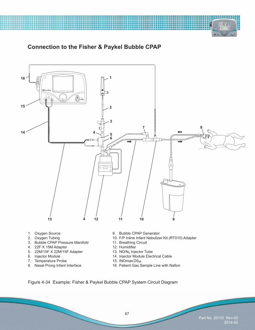
Part No. 20110 Rev-052014-02
67
1. Oxygen Source2. Oxygen Tubing3. Bubble CPAP Pressure Manifold4. 22F X 15M Adapter5. 22M/15F X 22M/15F Adapter6. Injector Module7. Temperature Probe8. Nasal Prong Infant Interface
9. Bubble CPAP Generator10. F/P Inline Infant Nebulizer Kit (RT010) Adapter11. Breathing Circuit12.Humidifier13. NO/N2 Injector Tube14. Injector Module Electrical Cable15. INOmax DSIR16.PatientGasSampleLinewithNafion
10 912
8
11
15
3
54
2
7
13
14
116
6
4
ConnectiontotheFisher&PaykelBubbleCPAP
Figure 4-34 Example: Fisher & Paykel Bubble CPAP System Circuit Diagram
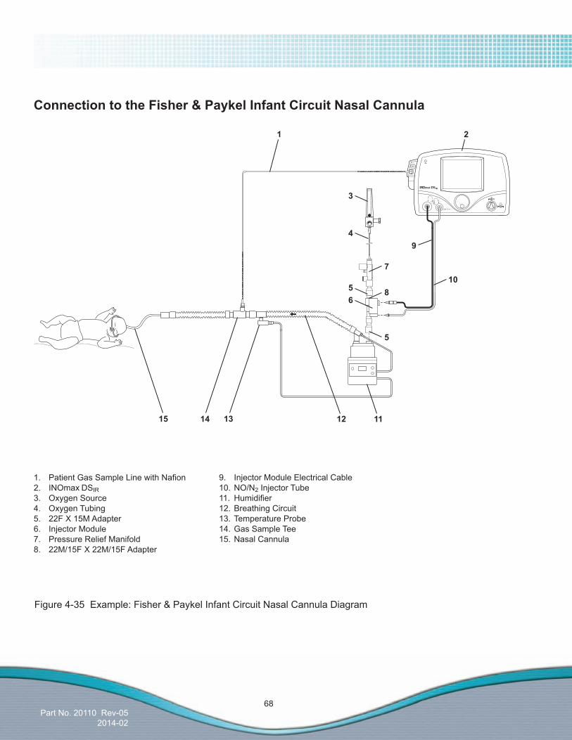
Part No. 20110 Rev-052014-02
68
1. PatientGasSampleLinewithNafion2. INOmax DSIR3. Oxygen Source4. Oxygen Tubing5. 22F X 15M Adapter6. Injector Module7. Pressure Relief Manifold8. 22M/15F X 22M/15F Adapter
9. Injector Module Electrical Cable10. NO/N2 Injector Tube11. Humidifier12. Breathing Circuit13. Temperature Probe14. Gas Sample Tee15. Nasal Cannula
1
12 11
10
15 1314
2
65
7
94
3
8
5
ConnectiontotheFisher&PaykelInfantCircuitNasalCannula
Figure 4-35 Example: Fisher & Paykel Infant Circuit Nasal Cannula Diagram

Part No. 20110 Rev-052014-02
69
1. PatientGasSampleLinewithNafion2. INOmax DSIR3. Oxygen Source4. Breathing Circuit Hose5. Injector Module6. Injector Module Electrical Cable7. NO/N2 Injector Tube8. 22F X 15M Adapter9. Humidifier
10. Breathing Circuit11. Temperature Probe12. Gas Sample Tee13. 22M/15F X 22M/15F Adapter14. 22 mm ID X 22 mm ID Cuff Adapter15.OptiflowTracheostomy16.OptiflowNasalCannula17.OptiflowMask
1214 1115
21
7
5
46
3
8
910
16
17
13
ConnectiontotheFisher&PaykelOptiflowBreathingCircuit
Figure4-36Example:Fisher&PaykelOptiflowBreathingCircuitDiagram

Part No. 20110 Rev-052014-02
70
Connection to the Hamilton Arabella Nasal CPAP
Caution: Refer to page 58 for a list of general precautions.
Figure 4-37 Example: Hamilton Arabella Nasal CPAP Circuit Diagram
Note: Connections to various ventilators as well as their corresponding disposable circuits, are unique to each manufacturer. For technical assistance, please contact Customer Support at the number on the back cover of this manual.
1. Arabella2. PatientGasSampleLinewithNafion3. INOmax DSIR4. NO/N2 Injector Tube5. Injector Module Electrical Cable6. Injector Module
7. 22F X 15M Adapter8. Humidifier9. Heated Delivery Circuit10. Temperature Probe11. Universal Generator12. 90 Degree Sample Port Adapter
8 7 5
31 2
9
12
11
6 410
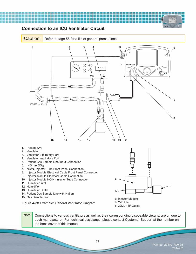
Part No. 20110 Rev-052014-02
71
ConnectiontoanICUVentilatorCircuit
Figure 4-38 Example: General Ventilator Diagram
1. Patient Wye2. Ventilator3. Ventilator Expiratory Port4. Ventilator Inspiratory Port5. Patient Gas Sample Line Input Connection6. INOmax DSIR7. NO/N2 Injector Tube Front Panel Connection8. Injector Module Electrical Cable Front Panel Connection9. Injector Module Electrical Cable Connection10. Injector Module NO/N2 Injector Tube Connection 11. HumidifierInlet 12.Humidifier 13.HumidifierOutlet14.PatientGasSampleLinewithNafion15. Gas Sample Tee
Caution: Refer to page 58 for a list of general precautions.
a. Injector Moduleb. 22F Inletc. 22M / 15F Outlet
b
a
c
1 2 6
9
8
1011
3 4 5
7
12131415
Note: Connections to various ventilators as well as their corresponding disposable circuits, are unique to each manufacturer. For technical assistance, please contact Customer Support at the number on the back cover of this manual.

Part No. 20110 Rev-052014-02
72
Figure 4-39 Example: High Frequency Oscillatory Ventilator Diagram
Note: Connections to various ventilators as well as their corresponding disposable circuits, are unique to each manufacturer. For technical assistance, please contact Customer Support at the number on the back cover of this manual.
Caution: Refer to page 58 for a list of general precautions.
WARNING: Omissionoftheone-wayvalvemayresultinhighNOdelivery.
ConnectiontoaSensormedics3100A/BHighFrequencyOscillatoryVentilator with a Filtered Circuit
1. Sensormedics 3100A/B Ventilator2. Ventilator Outlet3. 22M Adapter4. Injector Module5. Injector Module Electrical Cable Connection6. INOmax DSIR7. NO/N2 Injector Tube
1 2 4
6
a. Injector Moduleb. 22F Inletc. 22M / 15F Outlet
b
a
c
8. 15M Adapter9. One-Way Valve10. Paw Limit Valve Control11. Filter12.HumidifierInlet13.HumidifierOutlet
9
10
1112
15
11
13
1718
14
5
7
16
3
8
14. Bias Flow Tube15.PatientGasSampleLinewithNafion16. 90 Degree Sample Port Adapter17. Dump Valve Control18. Paw Control Valve
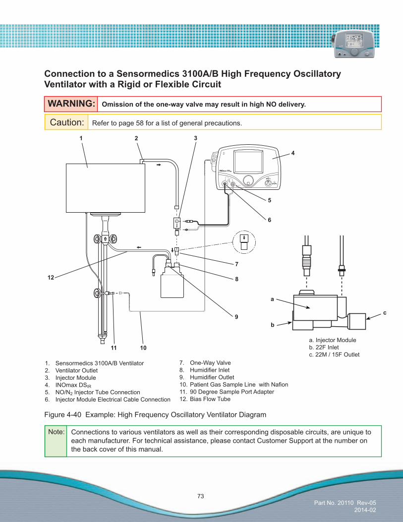
Part No. 20110 Rev-052014-02
73
WARNING: Omissionoftheone-wayvalvemayresultinhighNOdelivery.
ConnectiontoaSensormedics3100A/BHighFrequencyOscillatoryVentilatorwithaRigidorFlexibleCircuit
Figure 4-40 Example: High Frequency Oscillatory Ventilator Diagram
Note: Connections to various ventilators as well as their corresponding disposable circuits, are unique to each manufacturer. For technical assistance, please contact Customer Support at the number on the back cover of this manual.
1. Sensormedics 3100A/B Ventilator2. Ventilator Outlet3. Injector Module4. INOmax DSIR5. NO/N2 Injector Tube Connection6. Injector Module Electrical Cable Connection
1 2 3
4
a. Injector Moduleb. 22F Inletc. 22M / 15F Outlet
b
a
c
7. One-Way Valve8. HumidifierInlet9. HumidifierOutlet10.PatientGasSampleLinewithNafion11. 90 Degree Sample Port Adapter12. Bias Flow Tube
5
6
7
8
9
10
12
11
Caution: Refer to page 58 for a list of general precautions.
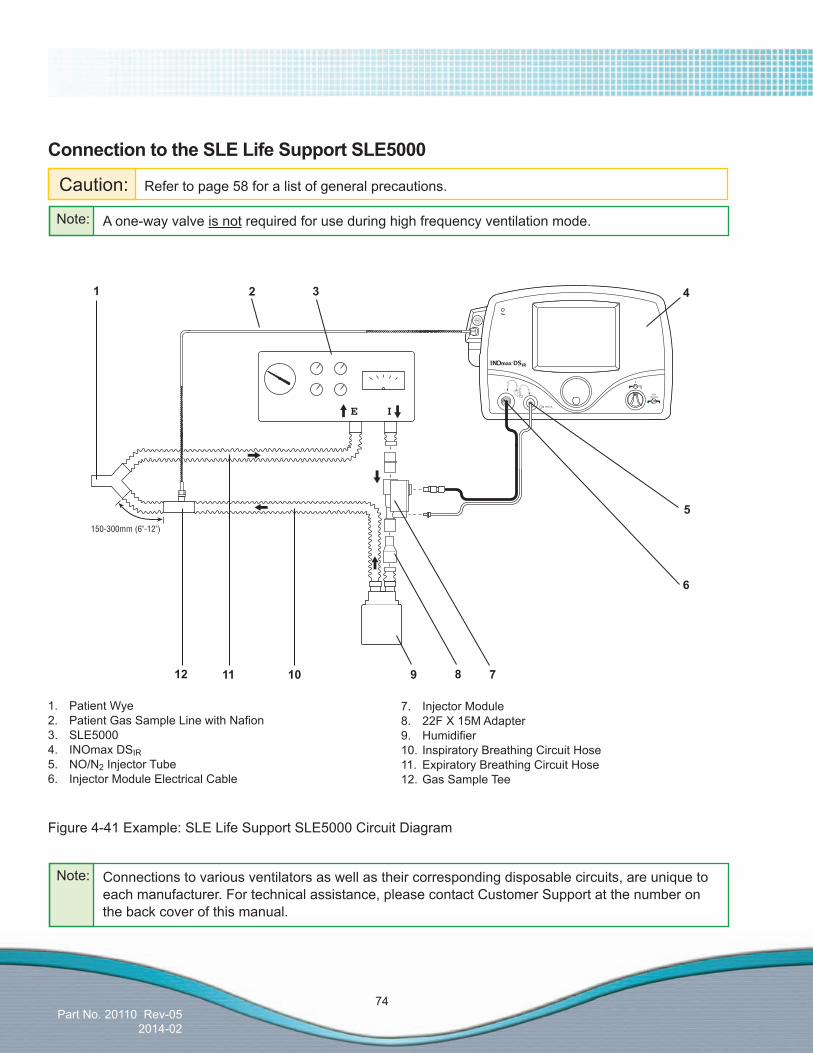
Part No. 20110 Rev-052014-02
74
ConnectiontotheSLELifeSupportSLE5000
Caution: Refer to page 58 for a list of general precautions.
Note: Connections to various ventilators as well as their corresponding disposable circuits, are unique to each manufacturer. For technical assistance, please contact Customer Support at the number on the back cover of this manual.
1. Patient Wye2. PatientGasSampleLinewithNafion3. SLE50004. INOmax DSIR5. NO/N2 Injector Tube6. Injector Module Electrical Cable
7. Injector Module8. 22F X 15M Adapter9. Humidifier10. Inspiratory Breathing Circuit Hose11. Expiratory Breathing Circuit Hose12. Gas Sample Tee
Figure 4-41 Example: SLE Life Support SLE5000 Circuit Diagram
Note: A one-way valve is not required for use during high frequency ventilation mode.
1 2 4
7
6
3
5
91012 811

Part No. 20110 Rev-052014-02
75
ConnectiontoSpontaneousBreathingPatientonaMaskCircuit
1. O2 Tubing2. 15M X 4.5mm Adapter3. 22M/15F X 22M/15F Adapter4. Breathing Circuit Tee5. Breathing Circuit Bag6. Injector Module7. Breathing Circuit Hose8. Gas Sample Tee
9. 22M/15F X 22M/15F Adapter10. One-Way Valve11. Sealed Face Mask12. One-Way Valve13.PatientGasSampleLinewithNafion14. NO/N2 Injector Tube15. Injector Module Electrical Cable16. O2 Flowmeter (wall outlet or cylinder)
Figure 4-42 Example: Spontaneous Breathing Patient Circuit Diagram
16
532 1061 7 12114 98
13
14
15

Part No. 20110 Rev-052014-02
76
1. O2 Flowmeter2. O2 Tubing3. 15M x 4.5mm Adapter4. 22M/15F x 22M/15F Adapter5. 300 mm of 22 mm Hose6. Injector Module
7. O2 Tubing Sample Tee8. Patient Nasal Cannula9.PatientGasSampleLinewithNafion10. NO/N2 Injector Tube11. Injector Module Electrical Cable
Connection to Spontaneous Breathing Patient on a Nasal CannulaThe INOmax DSIR can be used with nasal cannula to deliver INOMAX concentrations from 5-80 ppm and an oxygenflowrateaslowas2L/min.
Conditioningoftheoxygenflowpriortodeliverythroughtheinjectormodulewillhelpensurethemostaccurateflowmeasurement.Conditioningcanbeachievedbyadding300mmof22mmhosebetweentheoxygen tubing and the Injector Module.
WARNING: DonotusetheINOmaxDSIRbackupmodewithflowrateslessthan5L/min.
Figure 4-43 Example: Spontaneous Breathing Nasal Cannula Patient Circuit Diagram
4 5 432
1
6 5 34 7 8
1110
9
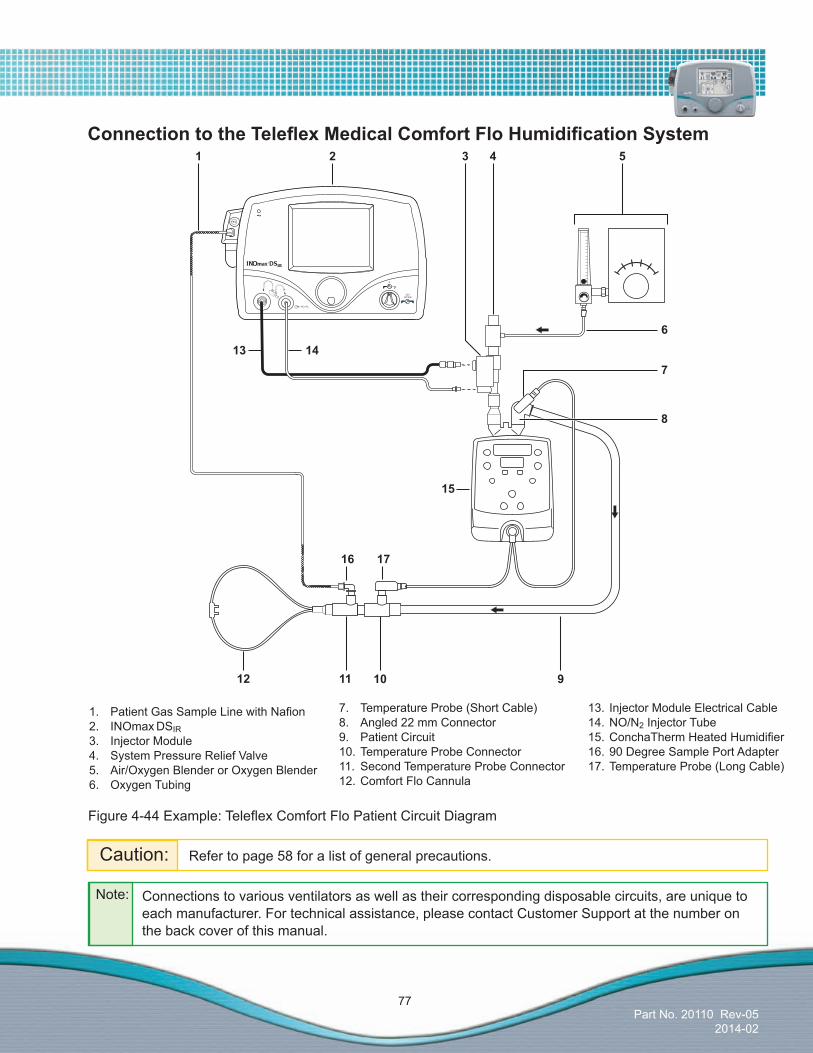
Part No. 20110 Rev-052014-02
77
1. PatientGasSampleLinewithNafion2. INOmax DSIR3. Injector Module4. System Pressure Relief Valve5. Air/Oxygen Blender or Oxygen Blender6. Oxygen Tubing
7. Temperature Probe (Short Cable)8. Angled 22 mm Connector9. Patient Circuit10. Temperature Probe Connector11. Second Temperature Probe Connector12. Comfort Flo Cannula
10
17
14
31 2
11
16
912
Figure4-44Example:TeleflexComfortFloPatientCircuitDiagram
ConnectiontotheTeleflexMedicalComfortFloHumidificationSystem
Caution: Refer to page 58 for a list of general precautions.
4 5
6
7
8
15
13
13. Injector Module Electrical Cable14. NO/N2 Injector Tube15.ConchaThermHeatedHumidifier16. 90 Degree Sample Port Adapter17. Temperature Probe (Long Cable)
Note: Connections to various ventilators as well as their corresponding disposable circuits, are unique to each manufacturer. For technical assistance, please contact Customer Support at the number on the back cover of this manual.

Part No. 20110 Rev-052014-02
78
ConnectiontoaTransportStyleVentilatorCircuit
Figure 4-45 Example: Transport Ventilator Diagram
Figure 4-46 Universal Mounting Post
1. Patient Wye2. Expiratory Breathing Circuit Hose3. PatientGasSampleLinewithNafion4. Ventilator Expiratory Valve
Caution: Refer to page 58 for a list of general precautions.
1
2
9
8
10
11
3
4
5
7
1213
6
5. Ventilator6. INOmax DSIR7. Ventilator Inspiratory Port8. 22M/15F X 22M/15F Adapter
9. Injector Module Electrical Cable10. NO/N2 Injector Tube11. Injector Module12. Inspiratory Breathing Circuit Hose13. Gas Sample Tee
Caution: •WhenusingtheTransportRegulator/Cap Assembly (PN 10022, CGA or 10041, ISO) ensure the cap is fully seated and in place on the INOmeter and the infrared cable is connected and latched to the infrared connector port on the back of the INOmax DSIR (see page 41).
• ItisrecommendedthatasecondTransport Regulator/Cap Assembly is available during all transports.
Figure 4-47
Note: Connections to various ventilators as well as their corresponding disposable circuits, are unique to each manufacturer. For technical assistance, please contact Customer Support at the number on the back cover of this manual.
Note: Do not attempt to connect the Transport Regulator Cap Assembly electrical plug to the INOblender outlet port. This will damage the connector plug electrical pins.
WARNING: IftheINOmaxDSIRistobeusedinatransportvehicle,itshouldbeaffixed tothetransportmountingpost(partnumber10009),seeFigure4-46.
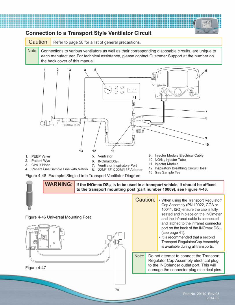
Part No. 20110 Rev-052014-02
79
ConnectiontoaTransportStyleVentilatorCircuit
Figure 4-48 Example: Single-Limb Transport Ventilator Diagram
1. PEEP Valve2. Patient Wye3. Circuit Hose4. PatientGasSampleLinewithNafion
1 2
9
8
10
11
3 4 5
7
1213
6
5. Ventilator6. INOmax DSIR7. Ventilator Inspiratory Port8. 22M/15F X 22M/15F Adapter
9. Injector Module Electrical Cable10. NO/N2 Injector Tube11. Injector Module12. Inspiratory Breathing Circuit Hose13. Gas Sample Tee
WARNING: IftheINOmaxDSIRistobeusedinatransportvehicle,itshouldbeaffixed tothetransportmountingpost(partnumber10009),seeFigure4-46.
Figure 4-46 Universal Mounting Post
Caution: •WhenusingtheTransportRegulator/Cap Assembly (PN 10022, CGA or 10041, ISO) ensure the cap is fully seated and in place on the INOmeter and the infrared cable is connected and latched to the infrared connector port on the back of the INOmax DSIR (see page 41).
• ItisrecommendedthatasecondTransport Regulator/Cap Assembly is available during all transports.
Figure 4-47
Note: Do not attempt to connect the Transport Regulator Cap Assembly electrical plug to the INOblender outlet port. This will damage the connector plug electrical pins.
Caution: Refer to page 58 for a list of general precautions.
Note: Connections to various ventilators as well as their corresponding disposable circuits, are unique to each manufacturer. For technical assistance, please contact Customer Support at the number on the back cover of this manual.

Part No. 20110 Rev-052014-02
80
Connection to the Vapotherm 2000i
Caution: Refer to page 58 for a list of general precautions.
Figure 4-49 Example: Vapotherm 2000i Circuit Diagram
1. INOmax DSIR2. O2 Flowmeter3. O2 Tubing4. 15M x 4.5 mm Adapter5. 22M/15F x 22M/15F Adapter6. 300 mm of 22 mm Hose7. 22M/15F x 22M/15F Adapter8. Injector Module9. 15M x 4.5 mm Adapter10. Vapotherm 2000i11. Patient Delivery Tube12. O2 Tubing Sample Tee13. Patient Cannula14.PatientGasSampleLinewithNafion15. NO/N2 Injector Tube16. Injector Module Electrical Cable
10
1
14
12
9
8
1516
11
7
6
54
3
2
13
• TheINOmaxDSIR adds NO/N2gasflowtothebreathingcircuitflowinproportiontotheNOsetting (up to 10% at 80 ppm for 800 ppm cylinder and 40 ppm for 400 ppm cylinder) and subtracts gas from the breathingcircuitviagassamplingatanominalflowrateof0.23L/min.
• TheseeffectsimpactthedeliveredgasflowratewhenusingtheVapotherm2000i.ItisrecommendedthatafteranNOsettingchangetheuserchecksthedeliveredgasflowrateandadjuststhegassourceflowrateasnecessary.
Note: Connections to various ventilators as well as their corresponding disposable circuits, are unique to each manufacturer. For technical assistance, please contact Customer Support at the number on the back cover of this manual.

Part No. 20110 Rev-052014-02
81
1. PatientGasSampleLinewithNafion2. INOmax DSIR3. Precision Flow Unit4. Injector Module5. Patient Delivery Tube6. Oxygen Tubing Sample Tee7. Patient Cannula8. Injector Module Electrical Cable9. NO/N2 Injector Tube
5
31 2
6
9
7
Figure 4-50 Example: Vapotherm Precision Flow Circuit Diagram
Connection to the Vapotherm Precision Flow
Caution: Refer to page 58 for a list of general precautions.
4
8
• TheINOmaxDSIR adds NO/N2gasflowtothebreathingcircuitflowinproportiontotheNOsetting (up to 10% at 80 ppm) and subtracts gas from the breathing circuit via gas sampling atanominalflowrateof0.23L/min.
• TheseeffectsimpactthedeliveredgasflowratewhenusingtheVapothermPrecisionFlow. ItisrecommendedthatafteranNOsettingchangetheuserchecksthedeliveredgasflow
rateandadjuststhegassourceflowrateasnecessary.• FollowallmanufacturerinstructionsforconnectiontotheVapothermPrecisionFlow.
Note: Connections to various ventilators as well as their corresponding disposable circuits, are unique to each manufacturer. For technical assistance, please contact Customer Support at the number on the back cover of this manual.

Part No. 20110 Rev-052014-02
82
(Intentionally left blank)

Part No. 20110 Rev-052014-02
83
ConnectiontotheViasysInfantFlowCPAPSystem;CardinalAirlifenCPAPSystem
Caution: Refer to page 58 for a list of general precautions.
Figure 4-51 Example: Viasys Infant Flow CPAP System Circuit Diagram
1. INOmax DSIR2. Heated Delivery Circuit3. Infant Flow System4. Infant Flow Generator5. Sample Tee6. Temperature Probe
7. PatientGasSampleLinewithNafion8. Humidifier9. 22F X 15M Adapter10. Injector Module11. NO/N2 Injector Tube12. Injector Module Electrical Cable
4
1 3
12
7 6 510 8911
2
Note: Connections to various ventilators as well as their corresponding disposable circuits, are unique to each manufacturer. For technical assistance, please contact Customer Support at the number on the back cover of this manual.

Part No. 20110 Rev-052014-02
84
Connection to the Viasys Infant Flow SiPAP
•TheINOmaxDSIR adds NO/N2gasflowtothebreathingcircuitflowinproportiontotheNOsetting(up to 10% at 80 ppm with 800 ppm cylinder or 40 ppm with 400 ppm cylinder) and subtracts gas fromthebreathingcircuitviagassamplingatanominalflowrateof0.23L/min.
•TheseeffectschangetheflowgoingtothenasaladapterandcanthereforeimpacttheCPAPlevelestablishedbyspecificflowsettings(Seetablebelow).Themaximumflowerrorisapproximately11%at2L/minwhichiswithintheaccuracyoftheflowmeterspecification(+/-15%).
•ItisrecommendedthatafteranNOsettingchangetheusercheckstheCPAPlevelontheInfantFlow SiPAP front panel display and adjusts as necessary.
Flow (L/min)
Flow (L/min)
Flow (L/min)
Flow (L/min)
Flow (L/min)
SiPAP Flow Setting 2 4 6 8 10After INOmax DSIR Set @ 0 ppm 1.77 3.77 5.77 7.77 9.77% error -11.5% -5.8% -3.8% -2.9% -2.3%After INOmax DSIR Set @ 80 ppm with 800 ppm cylinder
1.97 4.17 6.37 8.57 10.77
After INOmax DSIR Set @ 40 ppm with 400 ppm cylinder
1.97 4.17 6.37 8.57 10.77
% error -1.5% 4.3% 6.2% 7.1% 7.7%
Caution: Refer to page 58 for a list of general precautions.
Note: Connections to various ventilators as well as their corresponding disposable circuits, are unique to each manufacturer. For technical assistance, please contact Customer Support at the number on the back cover of this manual.

Part No. 20110 Rev-052014-02
85
Connection to the Viasys Infant Flow SiPAP
Figure 4-52 Example: Viasys Infant Flow SiPAP Circuit Diagram
1. INOmax DSIR2. Abdominal Respiratory Sensor3. Transducer Interface4. Infant Flow SiPAP5. Infant Flow Generator6. Sample Tee7. Temperature Probe
8. Heated Delivery Circuit9. Humidifier10. 22F X 15M Adapter11. Injector Module12. Injector Module Electrical Cable13. NO/N2 Injector Tube14.PatientGasSampleLinewithNafion
5
8 7 611 9
1 3 4
10
2
13
12
14

Part No. 20110 Rev-052014-02
86
(Intentionally left blank)

Part No. 20003 Rev - 01
(Delivery System)
Part No. 20110 Rev-052014-02
5/ Alarms
Alarm
s

(Delivery System)
Part No. 20110 Rev-052014-02
5/ Alarms
Ala
rms

Part No. 20110 Rev-052014-02
87
Alarm silencingPushing the Alarm Silence button will silence high-priority alarms for 120 seconds. When a new alarm condition occurs, the audible alarm becomes active again (see Figure 5-2).
A low-priority alarm event is permanently silenced when the Alarm Silence button is pressed. When a new low alarm condition occurs, the audible alarm becomes active again.
Alarm messages remain displayed during the alarm silence period as long as the alarm condition is active.
Figure 5-2 Alarm Silence Activated and Showing Counter Useradjustablemonitoralarms
The O2, NO2, and NO monitors have adjustable alarm settings that are displayed to the side of the monitored value.
The top button is the high-level alarm setting and the lower button is the low-level alarm setting (see Figure 5-2).
A low-alarm limit cannot be set above the high-limit setting.
When an alarm occurs for a monitored value, the violatedalarmsettingbuttonflashesRed (see Figure 5-2).
To adjust an alarm level to a new value, press the selected alarm level button on the touch screen, rotate the control wheel to adjust to the new level, andthenconfirmbypushingthecontrolwheelorthe selected alarm level button again.Ifthenewalarmlevelisnotconfirmedwithin20seconds, the alarm level defaults back to its previous value.
5/ Alarms
Figure 5-1 TextMessageAreaShowingfields1through4
General alarm informationA listing of alarm messages is provided at the end of this section.
All alarms have audible tones and visual messages.
Intheeventofatotalpowerfailureoramainalarmspeakerfailure,asecondaryaudiblealarmcircuitactivates,providingacontinuousbuzzingtonethatcannotbesilenced(seepage91).When exiting the Calibration Screen, a two-minute lockout period activates to prevent monitoring alarms from occurring while measured values stabilize.
High and low-priority alarmsThe INOmax DSIR has both high and low-alarm priorities.
High-priority alarms are accompanied with a red flashingAlarmSilencebutton.
Low-priority alarm conditions will display a continuous yellow Alarm Silence button.
High and low-priority alarm messages are displayed infields1through3(seeFigure5-1)withthemostrecentmessageshowninfield1.
Field 4 is used for status information such as “RunningonBattery”and“PatientInfo.Incomplete”.
Frequency Description CommentHigh Priority
400 Hz 10-pulse group Repeats after 10 sec. if not silenced.
Low Priority
400 Hz 1 pulse Repeats after 40 sec. if not silenced.
The following table provides the audible alarm tone information for high and low-priority alarms.
4321
1. Alarm Silence Button2. Alarm Silence Counter
3. Alarm Text4. Violated Monitored Value Limit
Caution: Do not set upper and lower alarm limits to extreme values which could render the alarm system useless.
Caution: •Anyalarmsetpointadjustments made will not be maintained when system power is cycled. •Defaultvalueswillbeusedfollowing a complete power loss (no AC main power and depleted battery).
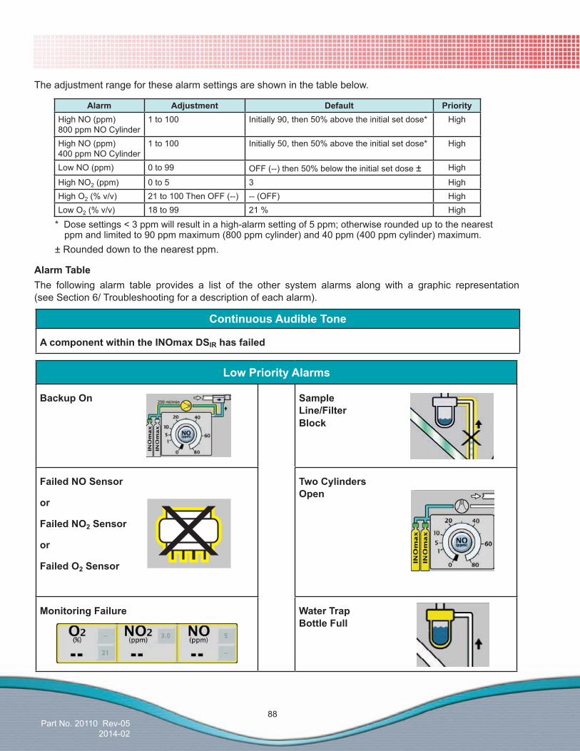
Part No. 20110 Rev-052014-02
88
LowPriorityAlarms
BackupOn Sample Line/Filter Block
FailedNOSensor
or
FailedNO2 Sensor
or
FailedO2 Sensor
TwoCylinders Open
MonitoringFailure WaterTrap Bottle Full
The adjustment range for these alarm settings are shown in the table below.
Alarm Adjustment Default PriorityHigh NO (ppm) 800 ppm NO Cylinder
1 to 100 Initially 90, then 50% above the initial set dose* High
High NO (ppm) 400 ppm NO Cylinder
1 to 100 Initially 50, then 50% above the initial set dose* High
Low NO (ppm) 0 to 99 OFF (--) then 50% below the initial set dose ± High
High NO2 (ppm) 0 to 5 3 HighHigh O2 (% v/v) 21 to 100 Then OFF (--) -- (OFF) HighLow O2 (% v/v) 18 to 99 21 % High
AlarmTableThe following alarm table provides a list of the other system alarms along with a graphic representation (see Section 6/ Troubleshooting for a description of each alarm).
* Dose settings < 3 ppm will result in a high-alarm setting of 5 ppm; otherwise rounded up to the nearest ppm and limited to 90 ppm maximum (800 ppm cylinder) and 40 ppm (400 ppm cylinder) maximum.
± Rounded down to the nearest ppm.
ContinuousAudibleTone
AcomponentwithintheINOmaxDSIR has failed

Part No. 20110 Rev-052014-02
89
High Priority Alarms
Cylinder Not Detected
InjectorModule Failure
Cylinder ValveClosed
LowBattery
Delivery Failure
PowertheINOmaxDSIR toSTANDBYandthen backONtoreset.
LowNO/N2 Pressure
Delivery Stopped
Service Required
Drug Concentration Mismatchor Drug Past ExpiryDate
SetNOand BackupOn
AlarmTablecontinued
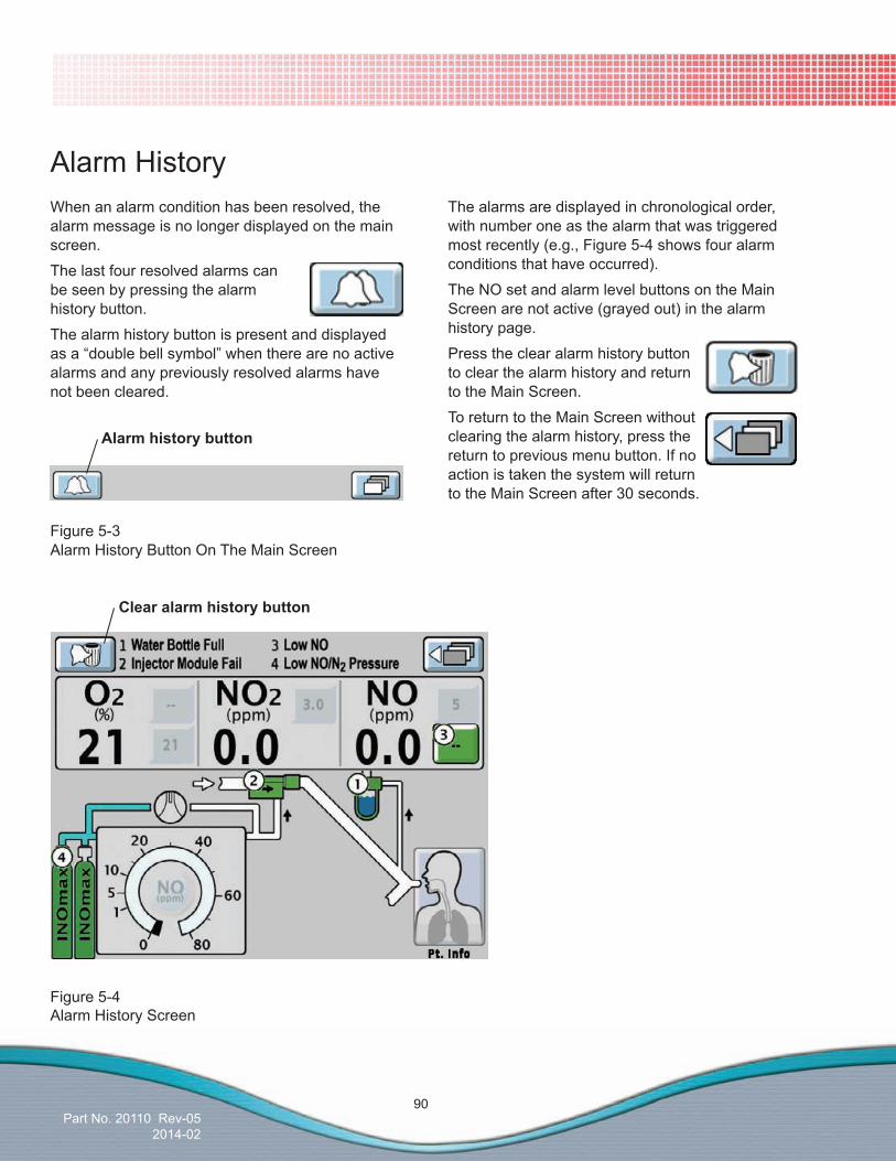
Part No. 20110 Rev-052014-02
90
Alarm HistoryWhen an alarm condition has been resolved, the alarm message is no longer displayed on the main screen.
The last four resolved alarms can be seen by pressing the alarm history button.
The alarm history button is present and displayed asa“doublebellsymbol”whentherearenoactivealarms and any previously resolved alarms have not been cleared.
The alarms are displayed in chronological order, with number one as the alarm that was triggered most recently (e.g., Figure 5-4 shows four alarm conditions that have occurred).
The NO set and alarm level buttons on the Main Screen are not active (grayed out) in the alarm history page.
Press the clear alarm history button to clear the alarm history and return to the Main Screen.
To return to the Main Screen without clearing the alarm history, press the return to previous menu button. If no action is taken the system will return to the Main Screen after 30 seconds.
Figure 5-3Alarm History Button On The Main Screen
Figure 5-4Alarm History Screen
Alarm history button
Clear alarm history button

Part No. 20003 Rev - 01
(Delivery System)
Part No. 20110 Rev-052014-02
6/ Troubleshooting
Troubleshooting
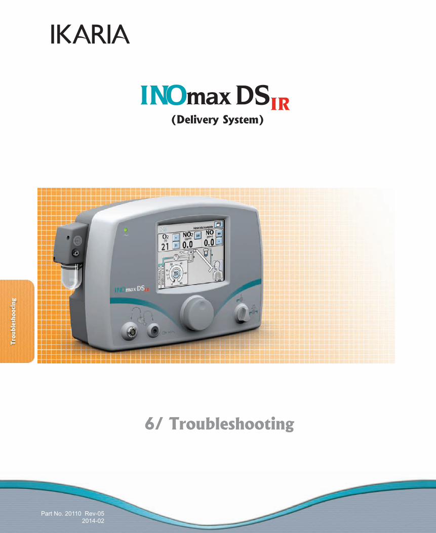
(Delivery System)
Part No. 20110 Rev-052014-02
6/ Troubleshooting
Trou
bles
hoot
ing

Part No. 20110 Rev-052014-02
91
High Priority AlarmsSymptom/Alarm Possible Cause Recommended Action
1. High NO alarm
A. Note: A newly installed NO sensor will give high readings until fully conditioned (about fivehours)andcalibrated.
a. After installation of the NO sensor, perform a low and high calibration.
b.Waitfivehoursandrepeatboththelowand high calibration.
B. The High NO alarm level may be inappropriately set.
a. Make sure the High NO alarm is set greater than the Set NO value.
C. The NO calibration may have drifted.
a. Perform a low and high-range calibration of the NO sensor.
b. Check calibration sample tee for leaks.D. Circuit setup incorrect. a. Check circuit setup for correct use of
adapters and/or check valves.
6/ TroubleshootingWARNING: UsecautionwhentroubleshootingtheINOmaxDSIR while in use on a patient. Whenpossible,replacetheunitinquestionandperformtroubleshooting proceduresoncetheunitisremovedfromthepatient.
TroubleshootingGuide
Continuous Audible Tone Continuous Audible Tone A. A component within the
INOmax DSIR has failed.a. If the INOblender is available, manually
ventilate the patient (see INOblender Operation Manual).
orb. Turn the backup mode ON (see page 40).c. Please contact Customer Support and
replace the delivery system as soon as possible.
If the system fails to operate properly:1. Check the patient condition and take appropriate action.2. Verify that the system is set up as detailed in Section 2/ Setup.3. Use the INOblender (see INOblender Operation Manual) or backup mode if necessary (see page 37).4. Find a symptom or alarm condition in the troubleshooting table below which best describes the problem and follow the recommended actions(s) to resolve the problem.If the problem can’t be corrected:Contact Customer Support at the number on the back cover of this manual.IftheINOmaxDSIR must be returned forservicing:1. Disconnect the following from the unit (refer to Figures 1-1 and 1-2.)
Removeandreturnwithunit 1. Injector module 2. Injector module cable 3. Power cord Removeanddiscard 1. Sample line 2. Injector tubing2. Pack the INOmax DSIR and the accessories as requested by Customer Support. Use the original or service loaner packaging materials to protect the system during transit. If the proper packaging is not available, please contact Customer Support at the number on the back cover of this manual. 3. Make sure the outside of the box is labeled: “FRAGILEMEDICALEQUIPMENT,HANDLE WITH CARE.”4.Sendtheunittothelocationspecifiedby
Customer Support at the number on the back cover of this manual.

Part No. 20110 Rev-052014-02
92
High Priority Alarms
Symptom/Alarm Possible Cause Recommended Action
2. Low NO alarm A. The Patient Gas Sample line may be disconnected.
a. Reconnect the Patient Gas Sample line.
B. The Low NO alarm setting may be inappropriately set.
a. Make sure the Low NO alarm is set less than the Set NO value.
C. The NO calibration may have drifted.
a. Perform a low and high-range calibration of the NO sensor.
D. The NO sensor may not be properly seated.
a. Make sure the sensors are correctly seated with the O-rings and the sensor cover is fully closed.
E. Loss of NO delivery. a. If the INOblender is available, manually ventilate the patient (see INOblender Operation Manual).
orb. Turn the backup mode ON (see page 40).
3. High NO2 alarm A. Incomplete System purge. a. Perform a system purge. See Section 3/ Pre-Use Checkout.
B.Ventilatorflowstopped. a.AllowtheventilatorgastoflushNOandNO2 from the breathing circuit before connecting to the patient.
C. Two cylinder valves are open. a. Close one of the cylinder valves.D. The NO2 alarm limit may be set
too low.a. Make sure the NO2 alarm limit is
appropriate for the Set NO level.E. The NO2 calibration may have
drifted.a. Perform a low and high range calibration
of the NO2 sensor.b. Check calibration sample tee for leaks.
F. Out of date or the wrong calibration gas was used.
a. Verify the calibration gas expiration date.b. If needed replace the calibration gas and
perform a low and high range calibration of the NO2 sensor.
G. The patient circuit setup may be incorrect.
a. Make sure the patient circuit hoses and lengths are correct (see Section 4/ Patient Application).
b.Verifythehumidifierchamberislessthan480 mL.
H. Sample line occlusion.In this case, this alarm may occur with a Sample Line Block alarm.
a.ConfirmwhethertheHighNO2 alarm occurs concurrently with a sample line block alarm.
b. If so, this alarm will clear within 10 seconds after the sample line alarm is remedied.
I. The INOmax DSIR may have failed.
a. Contact Customer Support.b. Replace the delivery system if in use.c. Do not use the delivery system until serviced.

Part No. 20110 Rev-052014-02
93
High Priority AlarmsSymptom/Alarm Possible Cause Recommended Action
4. High O2 alarm A. The O2 alarm setting may be inappropriate.
a. Make sure the High O2 alarm is set appropriately for the O2 setting being used on the ventilator.
B. The O2 calibration may have drifted.
a. Perform a low and high range calibration of the O2 sensor.
b. Change the O2 sensor if the monitor fails to calibrate.
c. Contact Customer Support.d. Replace the delivery system if in use.e. Do not use the delivery system until serviced.
5. Low O2 alarm A. The O2 concentration setting at the ventilator was reduced.
a. Make sure the O2 alarm setting is correct for the setting at the ventilator.
B. The O2 alarm setting may be inappropriate.
a. The INOmax DSIR can dilute the O2 concentration set at the ventilator by up to 10%.
b. Verify that the alarm is set appropriately for the O2 setting being used on the ventilator.
C. The O2 sensor may not be properly seated.
a. Make sure the sensors are correctly seated and the sensor cover is fully closed.
D. The O2 calibration may have drifted.
a. Perform a low and high range calibration of the O2 sensor.
b. Contact Customer Support. 6. Cylinder Not Detected
or
Cylinder Valve Closed
A. Interference with the Infrared communication link between the INOMAX cylinder and the INOmax DSIR (Delivery Stopped will occur one hour from the point when communication is lost).
a. Remove obstruction between the INOMAX cylinder and the INOmax DSIR.
b. Move the interfering IR/light or the cart to reduce the IR or high intensity light in the area of the INOmeter.
B. INOMAX cylinder valve is closed (Delivery Stopped will occur one hour from the point when the cylinder valve is closed).
a. Open INOMAX cylinder valve.
C. Transport Cap not connected to the INOmeter (Delivery Stopped will occur one hour from the point when communication is lost).
a. Attach the Transport Cap to the INOmeter on the INOMAX cylinder.
b. Connect the Transport Regulator/Cap Assembly cable to the infrared connector on the back of the INOmax DSIR.
D. INOMAX cylinder not present on the INOmax DSIR (Delivery Stopped will occur one hour from the point when communication is lost).
a. Load an INOMAX cylinder onto the INOmax DSIR cart.
E. INOmeter may have failed. a. Replace the INOMAX cylinder on the INOmax DSIR cart.
F. INOmax DSIR infrared cart cable is not connected or has failed.
a. Connect infrared cart cable to the infrared connector on the back of the INOmax DSIR.
b. Replace the INOmax DSIR system.
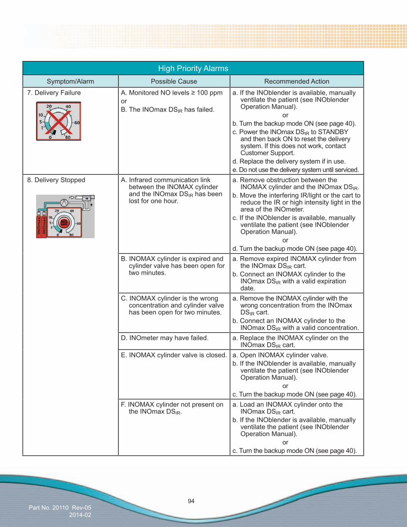
Part No. 20110 Rev-052014-02
94
High Priority AlarmsSymptom/Alarm Possible Cause Recommended Action
7. Delivery Failure A.MonitoredNOlevels≥100ppmorB. The INOmax DSIR has failed.
a. If the INOblender is available, manually ventilate the patient (see INOblender Operation Manual).
orb. Turn the backup mode ON (see page 40).c. Power the INOmax DSIR to STANDBY
and then back ON to reset the delivery system. If this does not work, contact Customer Support.
d. Replace the delivery system if in use.e. Do not use the delivery system until serviced.
8. Delivery Stopped A. Infrared communication link between the INOMAX cylinder and the INOmax DSIR has been lost for one hour.
a. Remove obstruction between the INOMAX cylinder and the INOmax DSIR.
b. Move the interfering IR/light or the cart to reduce the IR or high intensity light in the area of the INOmeter.
c. If the INOblender is available, manually ventilate the patient (see INOblender Operation Manual).
ord. Turn the backup mode ON (see page 40).
B. INOMAX cylinder is expired and cylinder valve has been open for two minutes.
a. Remove expired INOMAX cylinder from the INOmax DSIR cart.
b. Connect an INOMAX cylinder to the INOmax DSIR with a valid expiration date.
C. INOMAX cylinder is the wrong concentration and cylinder valve has been open for two minutes.
a. Remove the INOMAX cylinder with the wrong concentration from the INOmax DSIR cart.
b. Connect an INOMAX cylinder to the INOmax DSIR with a valid concentration.
D. INOmeter may have failed. a. Replace the INOMAX cylinder on the INOmax DSIR cart.
E. INOMAX cylinder valve is closed. a. Open INOMAX cylinder valve.b. If the INOblender is available, manually
ventilate the patient (see INOblender Operation Manual).
orc. Turn the backup mode ON (see page 40).
F. INOMAX cylinder not present on the INOmax DSIR.
a. Load an INOMAX cylinder onto the INOmax DSIR cart.
b. If the INOblender is available, manually ventilate the patient (see INOblender Operation Manual).
orc. Turn the backup mode ON (see page 40).

Part No. 20110 Rev-052014-02
95
High Priority Alarms
Symptom/Alarm Possible Cause Recommended Action
9. Drug Past Expiry Date Or Drug Concentration Mismatch
A. INOMAX cylinder is expired (Delivery Stopped will occur two minutes from the point when the cylinder valve is opened).
a. Close the cylinder valve.b. Remove expired INOMAX cylinder from
the INOmax DSIR cart.c. Replace the expired INOMAX cylinder on
the INOmax DSIR cart.B. INOMAX cylinder is the wrong
concentration (Delivery Stopped will occur two minutes from the point when the cylinder valve is opened).
a. Close the cylinder valve.b. Remove the INOMAX cylinder with the
wrong concentration from the INOmax DSIR cart.
c. Replace the INOMAX cylinder with the wrong concentration on the INOmax DSIR cart.
10. Injector Module Fail A. The Injector Module electrical cable may be disconnected.
a. Reconnect the Injector Module electrical cable.
b. Turn OFF the INOmax DSIR set dose to silence the alarm.
c. If the INOblender is available, manually ventilate the patient (see INOblender Operation Manual).
ord. Turn the backup mode ON (see page 40).
B. The Injector Module may have failed.
a. Turn OFF the INOmax DSIR set dose to silence the alarm.
b. If the INOblender is available, manually ventilate the patient (see INOblender Operation Manual).
orc. Turn the backup mode ON (see page 40).d. Replace the Injector Module.e. Set the delivered dose and turn OFF the
INOblender or the backup mode.C. The Injector Module electrical
cable may have failed.a. Turn OFF the INOmax DSIR set dose to
silence the alarm.b. If the INOblender is available, manually
ventilate the patient (see INOblender Operation Manual).
orc. Turn the backup mode ON (see page 40).d. Replace the Injector Module electrical
cable.e. Reset the delivered dose and turn OFF
the INOblender or the backup mode.

Part No. 20110 Rev-052014-02
96
High Priority AlarmsSymptom/Alarm Possible Cause Recommended Action
11. Low Battery Alarm. A. Battery is running low (approximately 30 minutes or less until battery depletion).
a. Check main power indicator.b. Connect to AC main power source.c. Make sure the power cord is fully
inserted into the Power Cord Inlet and that the power cord clamp is secure.
d. Check and replace fuse if necessary.e. Contact Customer Support.
12. Low NO/N2 Pressure. A. The NO cylinder supply may be low.
a. Make sure the NO cylinder is turned ON.b. If the high pressure cylinder gauge reads
less than 14 bar (200 psig), change the cylinder.
c. If the INOblender is available, manually ventilate the patient (see INOblender Operation Manual).
ord. Turn the backup mode ON (see page 40).
B. The supply line may not be connected.
a. If the cylinder gauge reads greater than 14 bar (200 psig):
b. Verify the low pressure hoses are connected correctly to the back of the INOmax DSIR.
c. If the INOblender is available, manually ventilate the patient (see INOblender Operation Manual).
ord. Turn the backup mode ON (see page 40).
C. INOmax DSIR has an internal leak.
a. Use INOblender as a stand-alone device and manually ventilate the patient (see page 121)
13. Service Required
Manual Delivery AvailableUtilize the INOblender or Backup Delivery.
A. The INOmax DSIR has failed. a. If the INOblender is available, manually ventilate the patient (see INOblender Operation Manual).
orb. Turn the backup mode ON (see page 40).c. Turn the INOmax DSIR to STANDBY and
then back ON to rest the delivery system. Please contact Customer Support and replace the delivery system as soon as possible.
14. Set NO and Backup On A. The backup mode has been turned ON and the set dose is still set.
a.Turn the INOmax DSIR set dose to zero.b. Correct the reason for initiating the
backup mode.c. Turn ON the INOmax DSIR set dose.d. Turn the backup mode OFF.e. If this does not work contact Customer
Support.
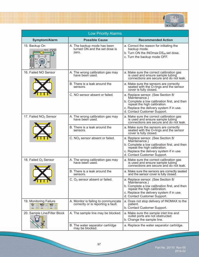
Part No. 20110 Rev-052014-02
97
Low Priority AlarmsSymptom/Alarm Possible Cause Recommended Action
15. Backup On A. The backup mode has been turned ON and the set dose is zero.
a. Correct the reason for initiating the backup mode.
b. Turn ON the INOmax DSIR set dose.c. Turn the backup mode OFF.
16. Failed NO Sensor A. The wrong calibration gas may have been used.
a. Make sure the correct calibration gas is used and ensure sample tubing connections are secure and do not leak.
B. There is a leak around the sensors.
a. Make sure the sensors are correctly seated with the O-rings and the sensor cover is fully closed.
C. NO sensor absent or failed. a. Replace sensor. (See Section 8/Maintenance.)
b.Completealowcalibrationfirst,andthenrepeat the high calibration.
c. Replace the delivery system if in use.d. Contact Customer Support.
17. Failed NO2 Sensor A. The wrong calibration gas may have been used.
a. Make sure the correct calibration gas is used and ensure sample tubing connections are secure and do not leak.
B. There is a leak around the sensors.
a. Make sure the sensors are correctly seated with the O-rings and the sensor cover is fully closed.
C. NO2 sensor absent or failed. a. Replace sensor. (See Section 8/Maintenance.)
b.Completealowcalibrationfirst,andthenrepeat the high calibration.
c. Replace the delivery system if in use.d. Contact Customer Support.
18. Failed O2 Sensor A. The wrong calibration gas may have been used.
a. Make sure the correct calibration gas is used and ensure sample tubing connections are secure and do not leak.
B. There is a leak around the sensors.
a. Make sure the sensors are correctly seated and the sensor cover is fully closed.
C. O2 sensor absent or failed. a. Replace sensor. (See Section 8/Maintenance.)
b.Completealowcalibrationfirst,andthenrepeat the high calibration.
c. Replace the delivery system if in use.d. Contact Customer Support.
19. Monitoring Failure A. Monitor is failing to communicate correctly or is reporting a fault.
a. Does not stop delivery of INOMAX to the patient.
b. Contact Customer Support. 20. Sample Line/Filter Block A. The sample line may be blocked. a. Make sure the sample inlet line and
outlet ports are not obstructed.b. Change the sample line.
B. The water separator cartridge may be blocked.
a. Replace the water separator cartridge.

Part No. 20110 Rev-052014-02
98
Indicators
Symptom/Indicator Possible Cause Recommended Action
23. Battery Failure A. Device cannot communicate with battery.
a. Connect to AC main power source when available.
b. Check main power indicator.c. Make sure the power cord is fully
inserted into the Power Cord Inlet and that the power cord clamp is secure.
24. Calibration Required A. Valve calibration required. a. No user action required. Return INOmax DSIR for service.
b. Contact Technical Support.
25. Patient Info Incomplete A.Patientidentifierhasnotbeenentered.
a.Enterpatientidentifier.
26. Running on Battery A. Device is operating on the battery.
a. Connect to AC main power source when available.
b. Check main power indicator.c. Make sure the power cord is fully
inserted into the Power Cord Inlet and that the power cord clamp is secure.
27. Set Dose is Zero, Close Cylinder Valve
A. The set dose has been set to zero and the INOMAX cylinder valve is still open.
a. Close the INOMAX cylinder valve if treatment has been stopped.
Low Priority Alarms
Symptom/Alarm Possible Cause Recommended Action
21. Two Cylinders Open A. Two cylinder valves are open. a. Close one of the cylinder valves.
22. Water Trap Bottle Full A. The water trap bottle on the side of the INOmax DSIR is full.
a. Empty the water trap bottle.
B. Water trap bottle is empty but the message remains in the alarm message box.
a. Remove the water trap bottle and clean the optical sensor level indicator with an alcohol swab.
C. The INOmax DSIR may have failed.
a. Contact Customer Support. b. Replace the delivery system if in use.
Part No. 20003 Rev - 01
(Delivery System)
Part No. 20110 Rev-052014-02
7/ Calibration
Calibration

(Delivery System)
Part No. 20110 Rev-052014-02
7/ Calibration
Cal
ibra
tion
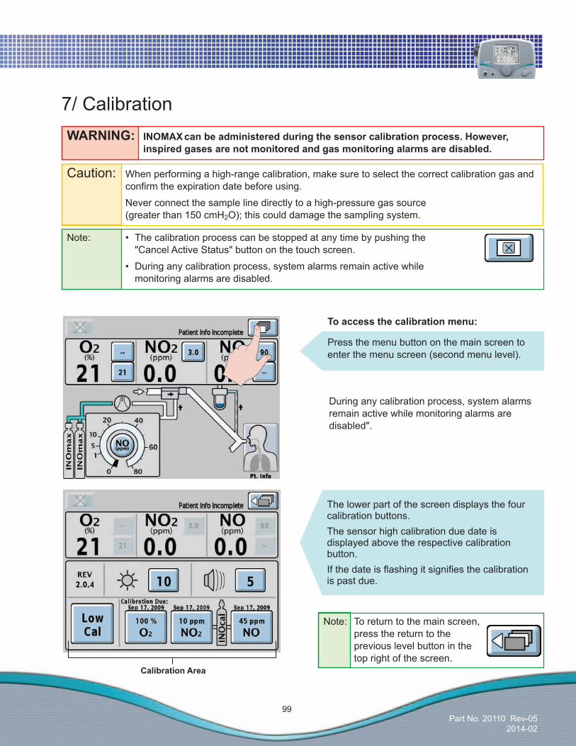
Part No. 20110 Rev-052014-02
99
Note: • Thecalibrationprocesscanbestoppedatanytimebypushingthe "Cancel Active Status" button on the touch screen.
• Duringanycalibrationprocess,systemalarmsremainactivewhile monitoring alarms are disabled.
7/ CalibrationWARNING: INOMAXcanbeadministeredduringthesensorcalibrationprocess.However, inspired gases are not monitored and gas monitoring alarms are disabled.
Caution: When performing a high-range calibration, make sure to select the correct calibration gas and confirmtheexpirationdatebeforeusing.
Never connect the sample line directly to a high-pressure gas source (greater than 150 cmH2O); this could damage the sampling system.
Toaccessthecalibrationmenu:
Press the menu button on the main screen to enter the menu screen (second menu level).
Calibration Area
Note: To return to the main screen, press the return to the previous level button in the top right of the screen.
The lower part of the screen displays the four calibration buttons.The sensor high calibration due date is displayed above the respective calibration button.Ifthedateisflashingitsignifiesthecalibrationis past due.
During any calibration process, system alarms remain active while monitoring alarms are disabled".
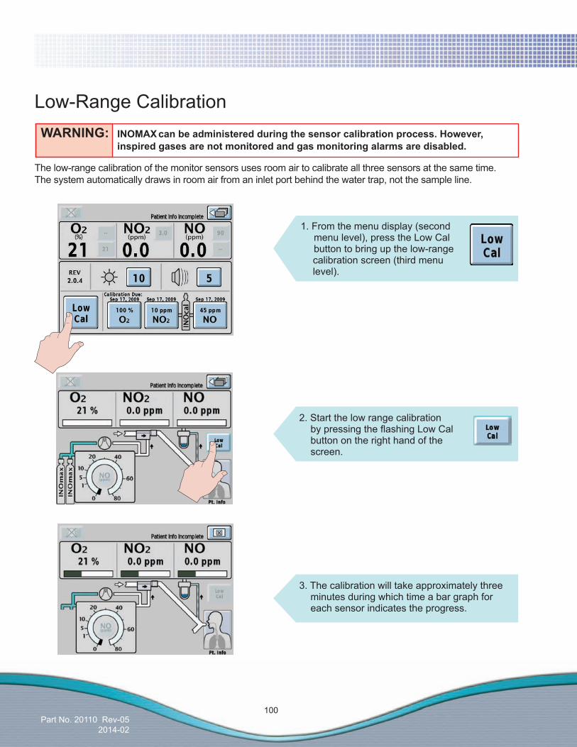
Part No. 20110 Rev-052014-02
100
Low-Range Calibration
1. From the menu display (second menu level), press the Low Cal button to bring up the low-range calibration screen (third menu level).
The low-range calibration of the monitor sensors uses room air to calibrate all three sensors at the same time. The system automatically draws in room air from an inlet port behind the water trap, not the sample line.
2. Start the low range calibration bypressingtheflashingLowCalbutton on the right hand of the screen.
WARNING: INOMAXcanbeadministeredduringthesensorcalibrationprocess.However, inspired gases are not monitored and gas monitoring alarms are disabled.
3. The calibration will take approximately three minutes during which time a bar graph for each sensor indicates the progress.
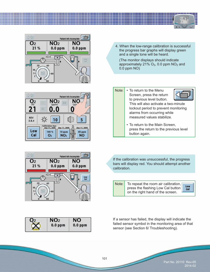
Part No. 20110 Rev-052014-02
101
Note: •ToreturntotheMenu Screen, press the return to previous level button. This will also activate a two-minute lockout period to prevent monitoring alarms from occurring while measured values stabilize.
•ToreturntotheMainScreen, press the return to the previous level button again.
Note: To repeat the room air calibration, presstheflashingLowCalbutton on the right hand of the screen.
If the calibration was unsuccessful, the progress bars will display red. You should attempt another calibration.
If a sensor has failed, the display will indicate the failed sensor symbol in the monitoring area of that sensor (see Section 6/ Troubleshooting).
4. When the low-range calibration is successful the progress bar graphs will display green and a single tone will be heard.
(The monitor displays should indicate approximately 21% O2, 0.0 ppm NO2 and 0.0 ppm NO)

Part No. 20110 Rev-052014-02
102
Oxygen Sensor High-Range Calibration
1. From the menu screen (second menu level) press the 100% O2 button to bring up the O2 high range calibration screen (third menu level). To return to the menu screen, press the return to previous level button.
3. To start the O2 high range calibration,presstheflashing 100% O2 button on the right hand side of the screen.
The oxygen high-range calibration requires a user-supplied source of 100% oxygen.
2. Assemble connectors into a calibration setup andsetoxygenflowto5L/min.
(1) 100% O2 Source (2) O2 Tubing (3) 15M X 4.5 mm I.D Adapter (4) Gas Sample Tee (5)PatientGasSampleLinewithNafion
WARNING: INOMAX canbeadministeredduringthesensorcalibrationprocess.However, inspired gases are not monitored and gas monitoring alarms are disabled.
1
2
5
3 4
Note: Aflashingdatesignifiesthecalibrationispast due.
Note: Complete a low calibration (see Low Range Calibration section) prior to completing the high calibration.
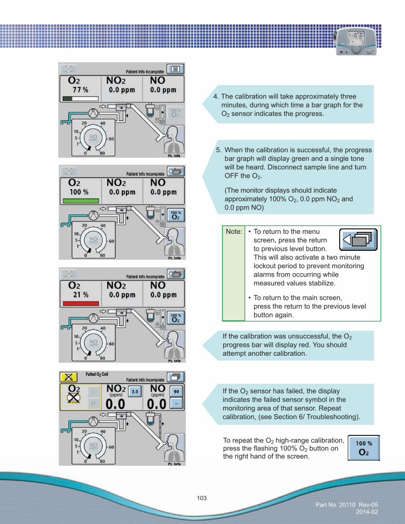
Part No. 20110 Rev-052014-02
103
If the O2 sensor has failed, the display indicates the failed sensor symbol in the monitoring area of that sensor. Repeat calibration, (see Section 6/ Troubleshooting).
5. When the calibration is successful, the progress bar graph will display green and a single tone will be heard. Disconnect sample line and turn OFF the O2.
(The monitor displays should indicate approximately 100% O2, 0.0 ppm NO2 and 0.0 ppm NO)
If the calibration was unsuccessful, the O2 progress bar will display red. You should attempt another calibration.
4. The calibration will take approximately three minutes, during which time a bar graph for the O2 sensor indicates the progress.
To repeat the O2 high-range calibration, presstheflashing100%O2 button on the right hand of the screen.
Note: •Toreturntothemenu screen, press the return to previous level button. This will also activate a two minute lockout period to prevent monitoring alarms from occurring while measured values stabilize.
•Toreturntothemainscreen, press the return to the previous level button again.
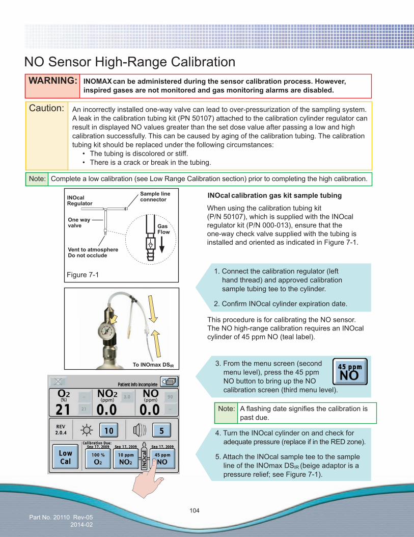
Part No. 20110 Rev-052014-02
104
NO Sensor High-Range Calibration
3. From the menu screen (second menu level), press the 45 ppm NO button to bring up the NO calibration screen (third menu level).
This procedure is for calibrating the NO sensor. The NO high-range calibration requires an INOcal cylinder of 45 ppm NO (teal label).
Caution: An incorrectly installed one-way valve can lead to over-pressurization of the sampling system. A leak in the calibration tubing kit (PN 50107) attached to the calibration cylinder regulator can result in displayed NO values greater than the set dose value after passing a low and high calibration successfully. This can be caused by aging of the calibration tubing. The calibration tubing kit should be replaced under the following circumstances:
• Thetubingisdiscoloredorstiff. • Thereisacrackorbreakinthetubing.
When using the calibration tubing kit (P/N 50107), which is supplied with the INOcal regulator kit (P/N 000-013), ensure that the one-way check valve supplied with the tubing is installed and oriented as indicated in Figure 7-1.
Sample line connector
Onewayvalve
Vent to atmosphere Do not occlude
Figure 7-1
INOcalcalibrationgaskitsampletubing
1. Connect the calibration regulator (left hand thread) and approved calibration sample tubing tee to the cylinder.
2.ConfirmINOcalcylinderexpirationdate.
WARNING: INOMAXcanbeadministeredduringthesensorcalibrationprocess.However, inspired gases are not monitored and gas monitoring alarms are disabled.
Gas Flow
INOcalRegulator
4. Turn the INOcal cylinder on and check for adequate pressure (replace if in the RED zone).
5. Attach the INOcal sample tee to the sample line of the INOmax DSIR (beige adaptor is a pressure relief; see Figure 7-1).
Note: Aflashingdatesignifiesthecalibrationis past due.
ToINOmaxDSIR
Note: Complete a low calibration (see Low Range Calibration section) prior to completing the high calibration.
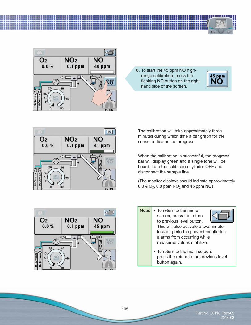
Part No. 20110 Rev-052014-02
105
When the calibration is successful, the progress bar will display green and a single tone will be heard. Turn the calibration cylinder OFF and disconnect the sample line.
(The monitor displays should indicate approximately 0.0% O2, 0.0 ppm NO2 and 45 ppm NO)
The calibration will take approximately three minutes during which time a bar graph for the sensor indicates the progress.
6. To start the 45 ppm NO high- range calibration, press the flashingNObuttonontheright hand side of the screen.
Note: •Toreturntothemenu screen, press the return to previous level button. This will also activate a two-minute lockout period to prevent monitoring alarms from occurring while measured values stabilize.
•Toreturntothemainscreen, press the return to the previous level button again.
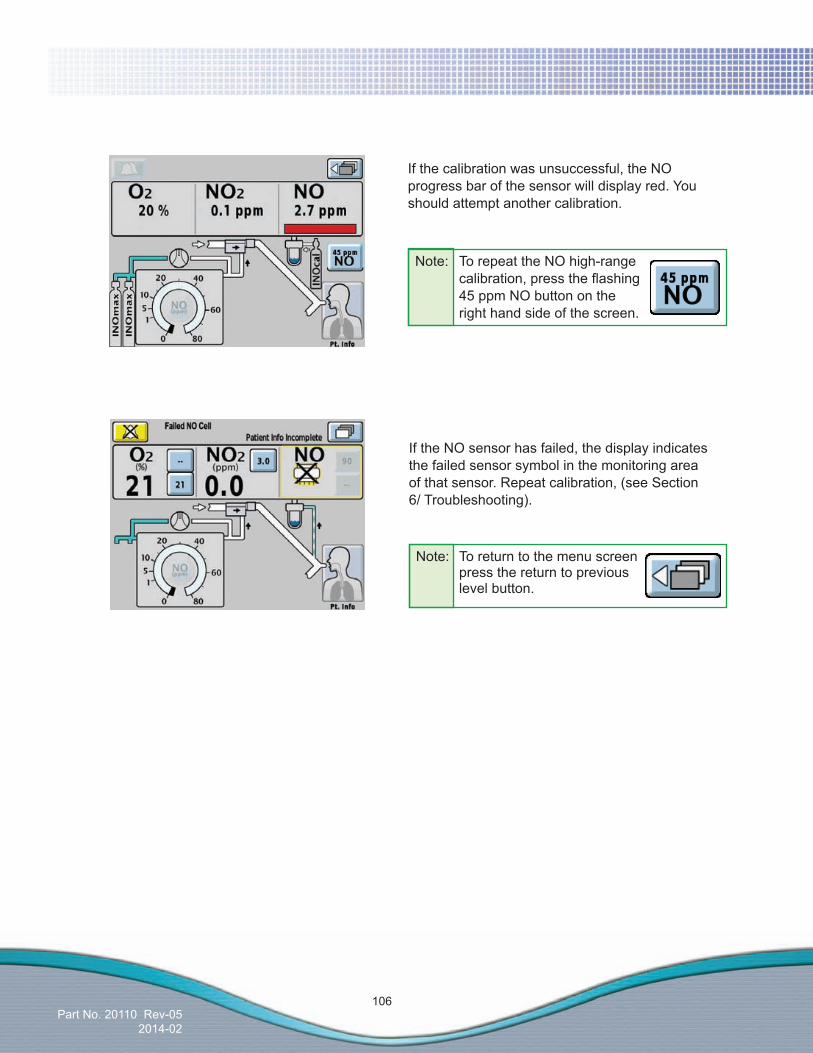
Part No. 20110 Rev-052014-02
106
If the calibration was unsuccessful, the NO progress bar of the sensor will display red. You should attempt another calibration.
Note: To repeat the NO high-range calibration,presstheflashing 45 ppm NO button on the right hand side of the screen.
If the NO sensor has failed, the display indicates the failed sensor symbol in the monitoring area of that sensor. Repeat calibration, (see Section 6/ Troubleshooting).
Note: To return to the menu screen press the return to previous level button.
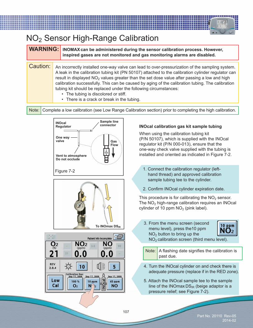
Part No. 20110 Rev-052014-02
107
Note: Aflashingdatesignifiesthecalibrationis past due.
1. Connect the calibration regulator (left- hand thread) and approved calibration sample tubing tee to the cylinder.
2.ConfirmINOcalcylinderexpirationdate.
INOcalcalibrationgaskitsampletubingWhen using the calibration tubing kit (P/N 50107), which is supplied with the INOcal regulator kit (P/N 000-013), ensure that the one-way check valve supplied with the tubing is installed and oriented as indicated in Figure 7-2.
3. From the menu screen (second menu level), press the10 ppm NO2 button to bring up the NO2 calibration screen (third menu level).
This procedure is for calibrating the NO2 sensor. The NO2 high-range calibration requires an INOcal cylinder of 10 ppm NO2 (pink label).
NO2 Sensor High-Range CalibrationWARNING: INOMAXcanbeadministeredduringthesensorcalibrationprocess.However, inspired gases are not monitored and gas monitoring alarms are disabled.
Sample line connector
Onewayvalve
Vent to atmosphere Do not occlude
Figure 7-2
Gas Flow
Caution: An incorrectly installed one-way valve can lead to over-pressurization of the sampling system. A leak in the calibration tubing kit (PN 50107) attached to the calibration cylinder regulator can result in displayed NO2 values greater than the set dose value after passing a low and high calibration successfully. This can be caused by aging of the calibration tubing. The calibration tubing kit should be replaced under the following circumstances:
• Thetubingisdiscoloredorstiff. • Thereisacrackorbreakinthetubing.
INOcalRegulator
4. Turn the INOcal cylinder on and check there is adequate pressure (replace if in the RED zone).
5. Attach the INOcal sample tee to the sample line of the INOmax DSIR (beige adaptor is a pressure relief; see Figure 7-2).
ToINOmaxDSIR
Note: Complete a low calibration (see Low Range Calibration section) prior to completing the high calibration.
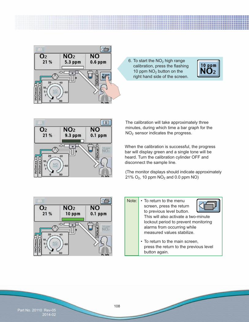
Part No. 20110 Rev-052014-02
108
The calibration will take approximately three minutes, during which time a bar graph for the NO2 sensor indicates the progress.
When the calibration is successful, the progress bar will display green and a single tone will be heard. Turn the calibration cylinder OFF and disconnect the sample line.
(The monitor displays should indicate approximately 21% O2, 10 ppm NO2 and 0.0 ppm NO)
6. To start the NO2 high range calibration,presstheflashing 10 ppm NO2 button on the right hand side of the screen.
Note: •Toreturntothemenu screen, press the return to previous level button. This will also activate a two-minute lockout period to prevent monitoring alarms from occurring while measured values stabilize.
•Toreturntothemainscreen, press the return to the previous level button again.
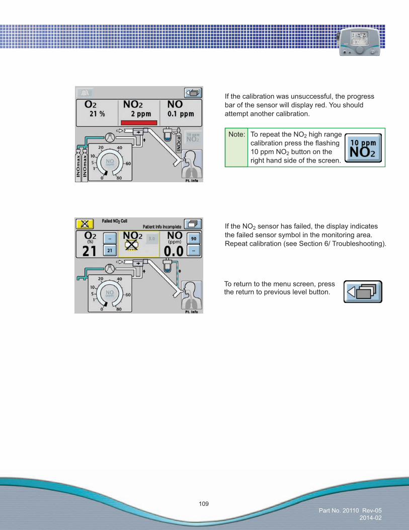
Part No. 20110 Rev-052014-02
109
If the NO2 sensor has failed, the display indicates the failed sensor symbol in the monitoring area. Repeat calibration (see Section 6/ Troubleshooting).
If the calibration was unsuccessful, the progress bar of the sensor will display red. You should attempt another calibration.
Note: To repeat the NO2 high range calibrationpresstheflashing 10 ppm NO2 button on the right hand side of the screen.
To return to the menu screen, press the return to previous level button.

Part No. 20110 Rev-052014-02
110
(Intentionally left blank)
Part No. 20003 Rev - 01
(Delivery System)
Part No. 20110 Rev-052014-02
8/ Maintenance
Maintenance

(Delivery System)
Part No. 20110 Rev-052014-02
8/ Maintenance
Mai
nten
ance
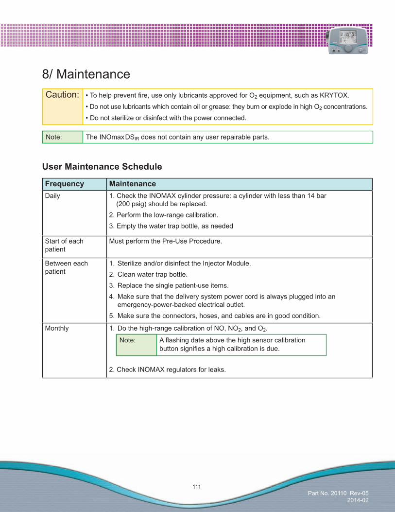
Part No. 20110 Rev-052014-02
111
Frequency MaintenanceDaily 1. Check the INOMAX cylinder pressure: a cylinder with less than 14 bar
(200 psig) should be replaced.2. Perform the low-range calibration. 3. Empty the water trap bottle, as needed
Start of each patient
Must perform the Pre-Use Procedure.
Between each patient
1. Sterilize and/or disinfect the Injector Module.2. Clean water trap bottle.3. Replace the single patient-use items.4. Make sure that the delivery system power cord is always plugged into an emergency-power-backed electrical outlet.5. Make sure the connectors, hoses, and cables are in good condition.
Monthly 1. Do the high-range calibration of NO, NO2, and O2.
2. Check INOMAX regulators for leaks.
Note: The INOmax DSIR does not contain any user repairable parts.
8/ MaintenanceCaution: •Tohelppreventfire,useonlylubricantsapprovedforO2 equipment, such as KRYTOX.
•Donotuselubricantswhichcontainoilorgrease:theyburnorexplodeinhighO2 concentrations.
•Donotsterilizeordisinfectwiththepowerconnected.
UserMaintenanceSchedule
Note: Aflashingdateabovethehighsensorcalibration buttonsignifiesahighcalibrationisdue.

Part No. 20110 Rev-052014-02
112
Caution: • DonotautoclaveorgassterilizetheINOmaxDSIR.
• Donotcleanwiththepowerconnected.
• Besurethattheunitiscompletelydrybeforeusingit.
• DonotsaturatetheINOmaxDSIRwithexcessivesolution.Liquidmayflowintothesystem and damage internal components.
• Donotuseorganic,petroleumbasedsolvents,glasscleaners,acetone,orotherharsh cleaning agents.
• Donotuseabrasivecleaningagents(suchassteelwool,silverpolishorcleaner).
• Donottouchorrubthedisplaypanelwithabrasivecleaningcompoundsoranythingwhich can scratch the panel.
• Donotuseorganicsolventstocleanthedisplaypanel.
Cleaning the INOmax DSIR
Caution: Apply cleaning agent to a cloth before application; do not spray cleaning agent directly on the delivery system to prevent pooling and direct contact with electrical connections which can cause damage over time.
Cleaning Procedure
External surfaces and the Display panel• Disconnectthepowerbeforecleaning.• CleantheoutersurfaceoftheINOmaxDSIR with a soft cloth dampened in a mild soap and water
solution, isopropyl alcohol (70%), or with one of the following cleaning agents while following the manufacturer’s recommendations.
Cleaning Agent ActiveIngredientsPrecise Hospital Foam Cleaner Disinfectant by Caltech Industries
o-Phenylphenol < 0.37%
Other ingredients 99.63%Pure Green 24 by Pure Green, LLC SDC–silverions0.003%
Citric acid 4.84%
Other ingredients 95.157%

Part No. 20110 Rev-052014-02
113
Cleaning Agent ActiveIngredientsPDI Super Sani Cloth by PDI n-Alkyl (68% C12, 32% C14) dimethyl ethylbenzyl
ammonium chlorides 0.25%
n-Alkyl (60% C14, 30% C16, 5% C12, 5% C18) dimethyl benzyl ammonium chlorides 0.25%
Isopropyl alcohol 55%
Inert ingredients 44.50%Sani Cloth HB by PDI n-Alkyl (60% C14, 30% C16, 5% C12, 5% C18)
dimethyl benzyl ammonium chlorides 0.07%
n-Alkyl (68% C12, 32% C14) dimethyl ethylbenzyl ammonium chlorides 0.07%
Inert ingredients 99.86%Asepti-HB by Ecolab Inc. n-Alkyl (60% C14, 30% C16, 5% C12, 5% C18)
dimethyl benzyl ammonium chlorides 0.07%
n-Alkyl (68% C12, 32% C14) dimethyl ethylbenzyl ammonium chlorides 0.07%
Inert ingredients 99.86%CavicideandCaviWipes by Metrex Diisobutylphenooxyethoxyethyl dimethyl benzyl
ammonium chloride 0.28%
Isopropyl alcohol 17.2%
Inert ingredients 82.52%
CleaningWaterTrapBottle
Procedure• Cleanwatertrapbottlewithasoftclothdampenedinamildsoapandwatersolutionorwithisopropylalcohol(70%).• Allowwatertrapbottletoairdry.
BioquellHydrogenPeroxideSterilantBioquell Hydrogen Peroxide Sterilant and hydrogen peroxide vapor generators are regulated by the US Environmental Protection Agency (EPA) as pesticide chemicals in accordance with Federal Insecticide, Fungicide, and Rodenticide Act (FIFRA). Use of these products in cleaning/disinfection processes have not been validated with the INOmax DSIR. Do not use these products to decontaminate the INOmax DSIR or any ancillary products used with the INOmax DSIR.
Caution: If alcohol is used to clean water trap bottle, make sure alcohol is completely evaporated before placing back onto sample block.
• AlcoholvaporswillcauseNO2 sensor to read high (as much as 6 ppm) and NO sensor to read low (approximately 0.5 to 1 ppm).
• Thisisatransientresponseandwillstoponcealcoholvaporsdissipate(trapdriesout).
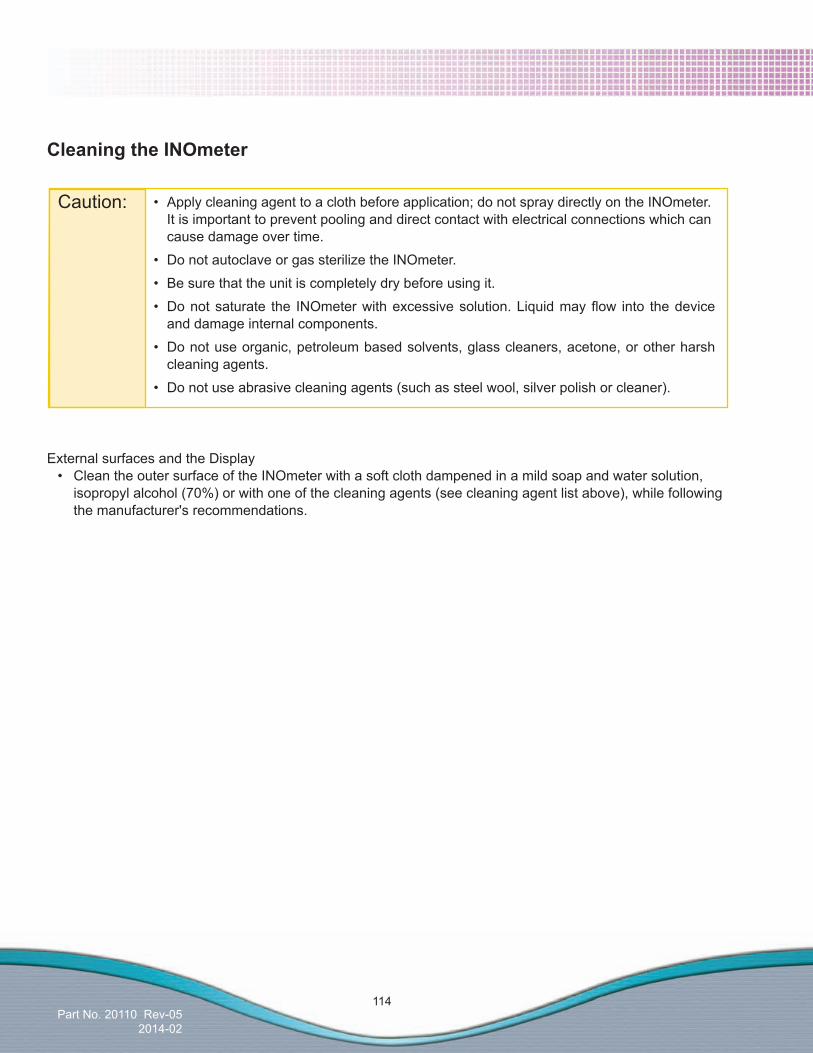
Part No. 20110 Rev-052014-02
114
CleaningtheINOmeter
External surfaces and the Display• CleantheoutersurfaceoftheINOmeterwithasoftclothdampenedinamildsoapandwatersolution,
isopropyl alcohol (70%) or with one of the cleaning agents (see cleaning agent list above), while following the manufacturer's recommendations.
Caution: • Applycleaningagenttoaclothbeforeapplication;donotspraydirectlyontheINOmeter. It is important to prevent pooling and direct contact with electrical connections which can cause damage over time.
• DonotautoclaveorgassterilizetheINOmeter.
• Besurethattheunitiscompletelydrybeforeusingit.
• Donotsaturate the INOmeterwithexcessivesolution.Liquidmayflow into thedevice and damage internal components.
• Donotuseorganic,petroleumbasedsolvents,glasscleaners,acetone,orotherharsh cleaning agents.
• Donotuseabrasivecleaningagents(suchassteelwool,silverpolishorcleaner).

Part No. 20110 Rev-052014-02
115
AutoclaveSterilizingtheInjectorModule1. Disconnect the electrical cable and the injector tube before autoclaving. 2. Autoclave settings: 134° C for three minutes at 1.85 bar (27 psig). 3. After sterilization, examine the parts. Any which are broken, worn, distorted or discolored should be replaced immediately.
Caution: • Iflintfibersremainwrappedaroundthehotwiresensorinthemoduleafterdrying,donotuse the module: remove it from service. • Donotphysicallyremovethefibersfromtheextremelydelicate sensor. Do not insert anything into the module throat to remove contamination or to dry.
DisinfectingtheInjectorModule1. Fill a container with ethyl alcohol (70% by volume). 2. Totally submerge the Injector Module in the alcohol for at least 30 minutes. 3.Toremovecontaminationiflintorfiberswerenoticedwrappedaroundthehotwire sensor in the module, gently agitate the module to splash the alcohol through the module openings. 4. If rinsing is required, use distilled water only. 5. When removing the module from the liquid, dump the excess alcohol from the modules’electricalconnector,injectorportandinsideflowmeter. 6. Allow any liquid to evaporate completely before using the module. •Usinglowairpressuretodrythemoduleorremovelintfiberisacceptable.
InjectorModuleSterilizingand/orDisinfecting
WARNING: IftheInjectorModulewasusedinthewet/humidifiedpartofthebreathingcircuit, it should be sterilized between each patient use.
Note: Patient circuit adapters, Patient Gas Sample Line, Injector Module tubing and water separator cartridge are single-patient use items. Do not sterilize them. Dispose of all single-patient use items in accordance with Universal Precautions for contamination.
Caution: Do not sterilize or disinfect with the power connected.
If the Injector Module has been used in the dry part of the breathing circuit, the Injector Module should be sterilized and/or disinfected in 70% ethyl alcohol after each patient use.
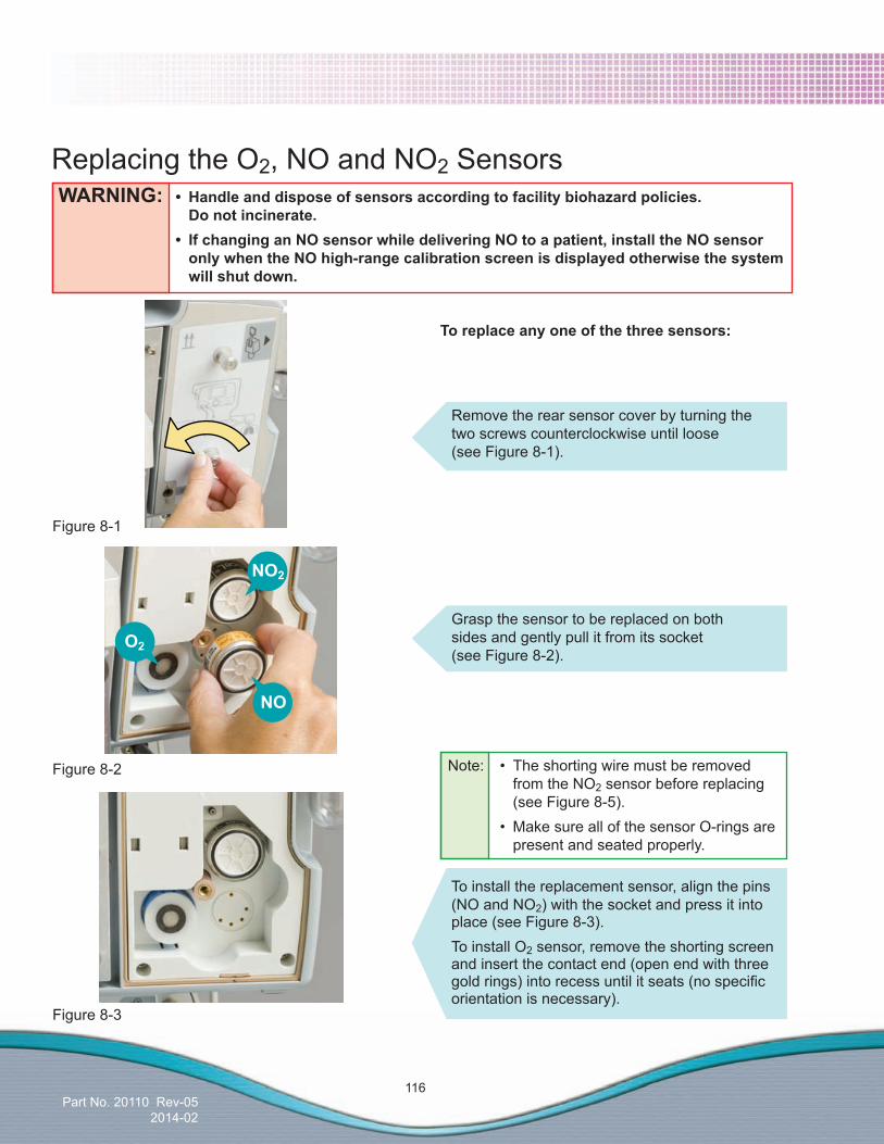
Part No. 20110 Rev-052014-02
116
WARNING: • Handleanddisposeofsensorsaccordingtofacilitybiohazardpolicies. Do not incinerate. • IfchanginganNOsensorwhiledeliveringNOtoapatient,installtheNOsensor onlywhentheNOhigh-rangecalibrationscreenisdisplayedotherwisethesystem will shut down.
Replacing the O2, NO and NO2 Sensors
Remove the rear sensor cover by turning the two screws counterclockwise until loose (see Figure 8-1).
Toreplaceanyoneofthethreesensors:
Grasp the sensor to be replaced on both sides and gently pull it from its socket (see Figure 8-2).
Note: • Theshortingwiremustberemoved from the NO2 sensor before replacing (see Figure 8-5). • MakesureallofthesensorO-ringsare present and seated properly.
Figure 8-1
Figure 8-2
Figure 8-3
NO2
O2
NO
To install the replacement sensor, align the pins (NO and NO2) with the socket and press it into place (see Figure 8-3).To install O2 sensor, remove the shorting screen and insert the contact end (open end with three goldrings)intorecessuntilitseats(nospecificorientation is necessary).

Part No. 20110 Rev-052014-02
117
Replace the sensor cover and tighten the two screws clockwise (see Figure 8-4).
Figure 8-4
Figure 8-5Shorting Wire
Replacing the O2, NO and NO2 Sensors (cont’d)
Perform a low and high calibration for the sensor before returning the system to use.
Note:Newly Installed Sensor Time to Condition Prior
to CalibrationO2 and NO2 40 minutes
NO 5 hoursInsufficientconditioningwillresultininaccurategas readings.
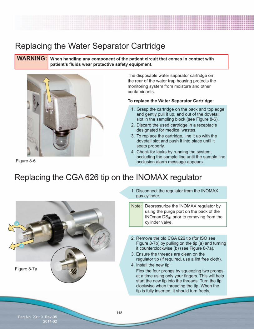
Part No. 20110 Rev-052014-02
118
The disposable water separator cartridge on the rear of the water trap housing protects the monitoring system from moisture and other contaminants.
ToreplacetheWaterSeparatorCartridge:
Replacing the Water Separator CartridgeWARNING: When handling any component of the patient circuit that comes in contact with patient’sfluidswearprotectivesafetyequipment.
Figure 8-6
Figure 8-7a
1. Grasp the cartridge on the back and top edge and gently pull it up, and out of the dovetail slot in the sampling block (see Figure 8-6).2. Discard the used cartridge in a receptacle designated for medical wastes.3. To replace the cartridge, line it up with the dovetail slot and push it into place until it seats properly. 4. Check for leaks by running the system, occluding the sample line until the sample line occlusion alarm message appears.
1. Disconnect the regulator from the INOMAX gas cylinder.
Replacing the CGA 626 tip on the INOMAX regulator
a
b
2. Remove the old CGA 626 tip (for ISO see Figure 8-7b) by pulling on the tip (a) and turning it counterclockwise (b) (see Figure 8-7a).
3. Ensure the threads are clean on the regulator tip (if required, use a lint free cloth).
4. Install the new tip: Flex the four prongs by squeezing two prongs atatimeusingonlyyourfingers.Thiswillhelp start the new tip into the threads. Turn the tip clockwise when threading the tip. When the tip is fully inserted, it should turn freely.
Note: Depressurize the INOMAX regulator by using the purge port on the back of the INOmax DSIR prior to removing from the cylinder valve.

Part No. 20110 Rev-052014-02
119
Figure 8-7b
2. Remove the old ISO O-ring by rolling it off its groove (see Figure 8-7b).
3. Clean the connector tip (if required, using a lint free cloth).
4. Roll the new O-ring into its groove. When correctly installed, it should not be removable by turning it.
Replacing the O-ring on the ISO 5145 INOMAX regulatorfitting
Caution: Do not use hard objects to remove the O-ring as they may damage the metal gland and cause a leak.
O-ring
Gland
1. Disconnect the regulator from the INOMAX therapy gas cylinder.
Note: Depressurize the INOMAX regulator by using the purge port on the back of the INOmax DSIR prior to removing from the cylinder valve.

Part No. 20110 Rev-052014-02
120
Figure 8-8
1. Cylinder Valve Regulator Connection2. INOMAX Regulator Hand Wheel Connection3. Regulator End Cap Connection4. Tamper Evident Tape5. Valve Nut6. Safety Pressure Release Device
6
5
1
2 3
4
Cylinder Leak CheckIf a leak is suspected during the high-pressure leak test (see Section 3/Pre-Use Checkout; High Pressure Leak Test), the following steps can be taken to check for leaks (see Figure 8-8 for possible cylinder gas leak locations) in the INOMAX regulator or INOMAX cylinder.
1. Ensure that INOMAX regulator is connected to cylinder valve outlet (hand-tighten only), cylinder valve is open and that the cylinder has more than 14 bar (200 psig).
2. Apply soapy water to points 1, 2, 3, 5 and 6 (see Figure 8-8); if bubbles form, there is a leak.
3. If there are no bubbles, leak may be inside INOmax DSIR and cannot be repaired. Replace INOmax DSIR and contact Customer Support.
Recommended actions should a leak be detected:1. A leak detected at points 1 and 2 (see Figure
8-8) may be corrected by tightening the INOMAX regulator hand wheel.a. If cylinder valve is open, close cylinder valve
and tighten INOMAX regulator hand wheel.b. Open cylinder valve and reapply soapy water
to points 1 and 2.c. If bubbles form, there is a leak.d. Remove INOMAX regulator and check for
damage. For the CGA type regulator connector, check the white plastic tip on INOMAX regulator for chips or cracks. Replace if necessary. For the ISO type regulator connector, check that the O-ring is present and is not damaged. Replace if necessary (see replacing the tip/O-ring on the INOMAX regulator, Page 118/119. Repeat step b (note: If leak remains, replace INOMAX regulator).
2. If a leak is detected between the regulator body and regulator end cap (see point 3), replace INOMAX regulator and contact Customer Support.
3. A leak detected at cylinder valve nut connection (see point 5) may not be repaired. Replace INOMAX cylinder and contact Customer Support.
4. A leak detected at safety pressure release device (see point 6) may not be repaired. Replace INOMAX cylinder and contact Customer Support.
Note: Refer to hospital policies and procedures for dealing with leaking gas cylinders. Additional information regarding environmental effects can be found in the section 1/General Information.
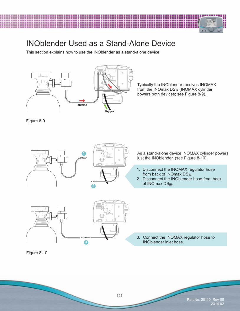
Part No. 20110 Rev-052014-02
121
INOblender Used as a Stand-Alone DeviceThis section explains how to use the INOblender as a stand-alone device.
As a stand-alone device INOMAX cylinder powers just the INOblender. (see Figure 8-10).
Figure 8-9
Figure 8-10
1. Disconnect the INOMAX regulator hose from back of INOmax DSIR.
2. Disconnect the INOblender hose from back of INOmax DSIR.
3. Connect the INOMAX regulator hose to INOblender inlet hose.
Typically the INOblender receives INOMAX from the INOmax DSIR (INOMAX cylinder powers both devices; see Figure 8-9).
1
2
3
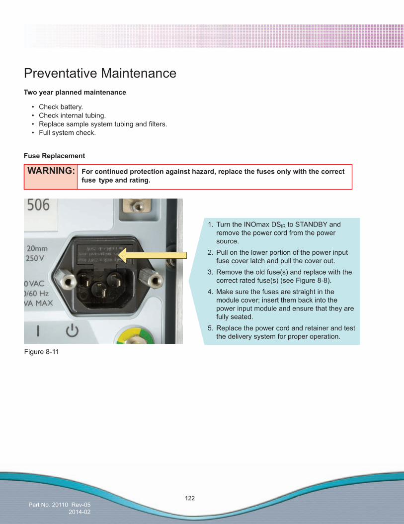
Part No. 20110 Rev-052014-02
122
Figure 8-11
WARNING: Forcontinuedprotectionagainsthazard,replacethefusesonlywiththecorrect fuse type and rating.
Twoyearplannedmaintenance
• Checkbattery. • Checkinternaltubing. • Replacesamplesystemtubingandfilters. • Fullsystemcheck.
Fuse Replacement
Preventative Maintenance
1. Turn the INOmax DSIR to STANDBY and remove the power cord from the power source.2. Pull on the lower portion of the power input fuse cover latch and pull the cover out.3. Remove the old fuse(s) and replace with the correct rated fuse(s) (see Figure 8-8). 4. Make sure the fuses are straight in the module cover; insert them back into the power input module and ensure that they are fully seated.5. Replace the power cord and retainer and test the delivery system for proper operation.

Part No. 20110 Rev-052014-02
123
Parts and Accessories
WARNING: Useonlyparts/accessoriesdesignatedforusewiththissystem.
Parts/Accessories Part Number Calibration Gas Regulator, for NO or NO2 Calibration Gas 90439Calibration Tubing Kit 50107Clamp Assembly 10008Injector Module 1605-3038-000Injector Module Cable 1605-3057-000INOcal Calibration Gas, NO, 45 ppm BOM-COM-0150INOcal Calibration Gas, NO2, 10 ppm BOM-COM-0162 INOcal Regulator Kit 000-013INOmax DSIR Cart (CGA) 10018INOmax DSIR Cart (Luxfer) 10045INOMAX Regulator, CGA 626 10006INOMAX Regulator, ISO 5145, Left 10020INOMAX Regulator, ISO 5145, Right 10072INOMAX Regulator Extension Hose 10014INOMAX Transport Regulator/Cap Assembly, CGA 626 10022INOMAX Transport Regulator/Cap Assembly, ISO 5145 10041Mounting Post 10009O-ring, ISO 5145 INOMAX Regulator 80470Sensor, O2 80043Sensor, NO 6050-0004-318Sensor, NO2 6050-0004-319Tip, CGA 626 INOMAX Regulator 1605-3149-000Transport Mounting Bracket Assembly 50041Water Trap Bottle 90137

Part No. 20110 Rev-052014-02
124
Disposables (Note: Graphics not actual size) Part Number
Adapter, 90 degree Sample Port 80325
Bunnell Life Pulse Disposable Adapters Convenience Pack 50046
Disk Filter, 0.5 micron 80333
NO/N2 Injector Tube 1605-3044-000
One-way Valve, 22F X 22M 1605-3139-000
Patient Gas Sample Line(Nafion) 90509
Sample Tee, O2 Tubing 1605-3171-000
Sensormedics 3100A/B Filtered Circuit Disposable Adapters Convenience Pack 50071
Water Separator Cartridge 50017

Part No. 20110 Rev-052014-02
125
OperationandMaintenanceManual Part NumberEnglish 20110Czech 20269Danish 20270Dutch 20271Finnish 20272French-EU 20273French-Canadian 20040German 20274Hungarian 20275Italian 20276Japanese 20075Korean 20277Norwegian 20278Polish 20279Portuguese 20280Spanish-EU 20281Spanish-LATAM 20304Swedish 20282

Part No. 20110 Rev-052014-02
126
Electrical Power CordCountry *ConnectionType Part Number Required FastenersArgentina IRAM 2073:1982 80474 Cord Retainer - 90181
Cord Standoff - 80248
Australia New Zealand
AS/NZS 3112:2000 80246
Denmark Danish Medical DK-2-8A 80253
ArgentinaChileCzech RepublicFinlandFranceGermanyHungaryNetherlandsNorwayPolandPortugalSouth KoreaSpainSwedenUruguay
CEE 7/7SchukoStraight or Right Angle Power Cord Plug
*Straight - 80472Right Angle - 80473
Chile ItalyUruguay
CEI 23-16 80471
ColumbiaJapanUSA
NEMA 5-15 1605-3047-000
Switzerland SEV1011 80475
UK/Ireland BS1363 80245
*Straight Shown.Images for reference only.

Part No. 20003 Rev - 01
(Delivery System)
Part No. 20110 Rev-052014-02
9/ Product Specifications
(Delivery System)
Part No. 20110 Rev-052014-02
9/ Product Specifications
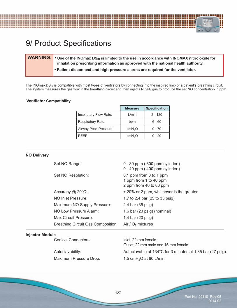
Part No. 20110 Rev-052014-02
127
The INOmax DSIR is compatible with most types of ventilators by connecting into the inspired limb of a patient’s breathing circuit. ThesystemmeasuresthegasflowinthebreathingcircuitandtheninjectsNO/N2 gas to produce the set NO concentration in ppm.
WARNING:•UseoftheINOmaxDSIRislimitedtotheuseinaccordancewithINOMAXnitricoxideforinhalationprescribinginformationasapprovedwiththenationalhealthauthority.
•Patientdisconnectandhigh-pressurealarmsarerequiredfortheventilator.
9/ProductSpecifications
Measure Specification
Inspiratory Flow Rate: L/min 2 - 120
Respiratory Rate: bpm 6 - 60
Airway Peak Pressure: cmH2O 0 - 70
PEEP: cmH2O 0 - 20
Ventilator Compatibility
NODelivery
Set NO Range: 0 - 80 ppm ( 800 ppm cylinder ) 0 - 40 ppm ( 400 ppm cylinder ) Set NO Resolution: 0.1 ppm from 0 to 1 ppm 1 ppm from 1 to 40 ppm 2 ppm from 40 to 80 ppm Accuracy @ 20°C: ± 20% or 2 ppm, whichever is the greater NO Inlet Pressure: 1.7 to 2.4 bar (25 to 35 psig) Maximum NO Supply Pressure: 2.4 bar (35 psig) NO Low Pressure Alarm: 1.6 bar (23 psig) (nominal) Max Circuit Pressure: 1.4 bar (20 psig) Breathing Circuit Gas Composition: Air / O2 mixtures
InjectorModule Conical Connectors: Inlet, 22 mm female. Outlet, 22 mm male and 15 mm female.
Autoclavability: Autoclavable at 134°C for 3 minutes at 1.85 bar (27 psig).
Maximum Pressure Drop: 1.5 cmH2O at 60 L/min
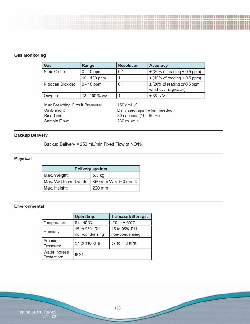
Part No. 20110 Rev-052014-02
128
GasMonitoring
Gas Range Resolution AccuracyNitric Oxide: 0 - 10 ppm 0.1 ± (20% of reading + 0.5 ppm)
10 - 100 ppm 1 ± (10% of reading + 0.5 ppm)Nitrogen Dioxide: 0 - 10 ppm 0.1 ± (20% of reading or 0.5 ppm
whichever is greater)Oxygen: 18 - 100 % v/v 1 ± 3% v/v
Max Breathing Circuit Pressure: 150 cmH20 Calibration: Daily zero; span when needed Rise Time: 30 seconds (10 - 90 %) Sample Flow: 230 mL/min
BackupDelivery
BackupDelivery=250mL/minFixedFlowofNO/N2
Physical
DeliverysystemMax. Weight: 5.3 kgMax. Width and Depth: 350 mm W x 160 mm DMax. Height: 220 mm
Environmental
Operating: Transport/Storage:Temperature: 5 to 40°C -20 to + 60°C
Humidity: 15 to 95% RH non-condensing
15 to 95% RH non-condensing
Ambient Pressure: 57 to 110 kPa 57 to 110 kPa
Water Ingress Protection: IPX1
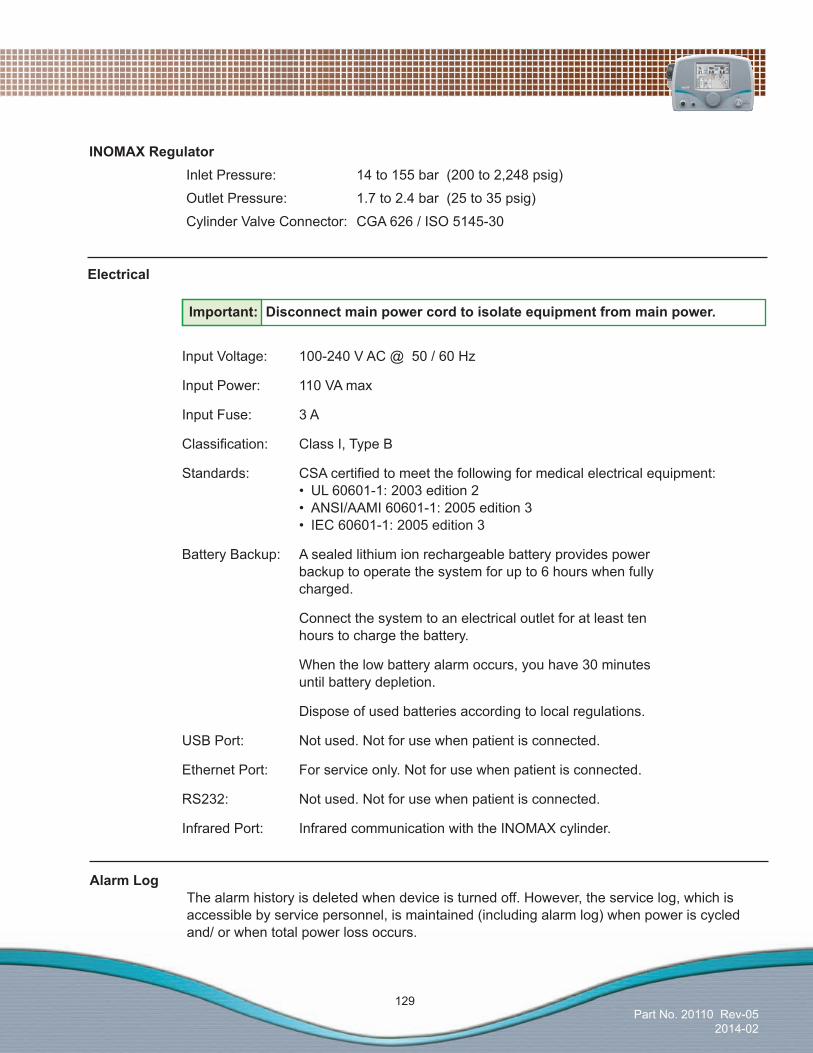
Part No. 20110 Rev-052014-02
129
Electrical
Input Voltage: 100-240 V AC @ 50 / 60 Hz
Input Power: 110 VA max
Input Fuse: 3 A
Classification: Class I, Type B
Standards: CSAcertifiedtomeetthefollowingformedicalelectricalequipment: • UL60601-1:2003edition2 • ANSI/AAMI60601-1:2005edition3 • IEC60601-1:2005edition3
Battery Backup: A sealed lithium ion rechargeable battery provides power backup to operate the system for up to 6 hours when fully charged.
Connect the system to an electrical outlet for at least ten hours to charge the battery.
When the low battery alarm occurs, you have 30 minutes until battery depletion.
Dispose of used batteries according to local regulations.
USB Port: Not used. Not for use when patient is connected.
Ethernet Port: For service only. Not for use when patient is connected.
RS232: Not used. Not for use when patient is connected.
Infrared Port: Infrared communication with the INOMAX cylinder.
Important: Disconnect main power cord to isolate equipment from main power.
INOMAXRegulator Inlet Pressure: 14 to 155 bar (200 to 2,248 psig)
Outlet Pressure: 1.7 to 2.4 bar (25 to 35 psig)
Cylinder Valve Connector: CGA 626 / ISO 5145-30
AlarmLog The alarm history is deleted when device is turned off. However, the service log, which is accessible by service personnel, is maintained (including alarm log) when power is cycled and/ or when total power loss occurs.

Part No. 20110 Rev-052014-02
130
Electromagnetic Compatibility Information
GuidanceandManufacturer’sDeclaration–ElectromagneticEmissionsThe INOmax DSIRsystemisintendedforuseintheelectromagneticenvironmentspecifiedbelow.Theuser of the INOmax DSIR system should assure that it is used in such an environment.
EmissionsTest Compliance ElectromagneticEnvironment-Guidance
RF emissionsCISPR 11
Group 1 The INOmax DSIR system uses RF energy only for its internal function. Therefore, its RF emissions are very low and are not likely to cause any interference in nearby electronic equipment.
RF emissionsCISPR 11
Class B The INOmax DSIR system is suitable for use in all establishments, including domestic establishments and those directly connected to the public low voltage power supply network that supplies buildings used for domestic purposes.
Harmonic emissionsIEC 61000-3-2
Class B
Voltagefluctuations/flickeremissionsIEC 61000-3-3
Complies
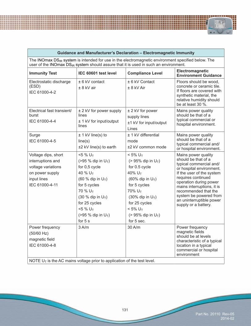
Part No. 20110 Rev-052014-02
131
GuidanceandManufacturer’sDeclaration–ElectromagneticImmunity
The INOmax DSIR system isintendedforuseintheelectromagneticenvironmentspecifiedbelow.Theuser of the INOmax DSIR system should assure that it is used in such an environment.
ImmunityTest IEC60601testlevel ComplianceLevel Electromagnetic EnvironmentGuidance
Electrostatic discharge (ESD)IEC 61000-4-2
± 6 kV contact± 8 kV air
± 6 kV Contact ± 8 kV Air
Floors should be wood, concrete or ceramic tile. Iffloorsarecoveredwithsynthetic material, the relative humidity should be at least 30 %.
Electrical fast transient/burstIEC 61000-4-4
± 2 kV for power supply lines± 1 kV for input/output lines
± 2 kV for powersupply lines±1 kV for input/outputLines
Mains power quality should be that of a typical commercial or hospital environment.
SurgeIEC 61000-4-5
± 1 kV line(s) toline(s)±2 kV line(s) to earth
± 1 kV differentialmode±2 kV common mode
Mains power quality should be that of a typical commercial and/or hospital environment.
Voltage dips, shortinterruptions andvoltage variationson power supplyinput linesIEC 61000-4-11
<5 % UT
(>95 % dip in UT)for 0,5 cycle40 % UT
(60 % dip in UT)for 5 cycles70 % UT
(30 % dip in UT)for 25 cycles<5 % UT
(>95 % dip in UT)for 5 s
< 5% UT
(> 95% dip in UT) for 0.5 cycle40% UT
(60% dip in UT) for 5 cycles70% UT
(30% dip in UT) for 25 cycles< 5% UT
(> 95% dip in UT) for 5 sec.
Mains power quality should be that of a typical commercial and/or hospital environment. If the user of the system requires continued operation during power mains interruptions, it is recommended that the system be powered from an uninterruptible power supply or a battery.
Power frequency(50/60 Hz)magneticfieldIEC 61000-4-8
3 A/m 30 A/m Power frequency magneticfieldsshould be at levels characteristic of a typical location in a typical commercial or hospital environment
NOTE UT is the AC mains voltage prior to application of the test level.
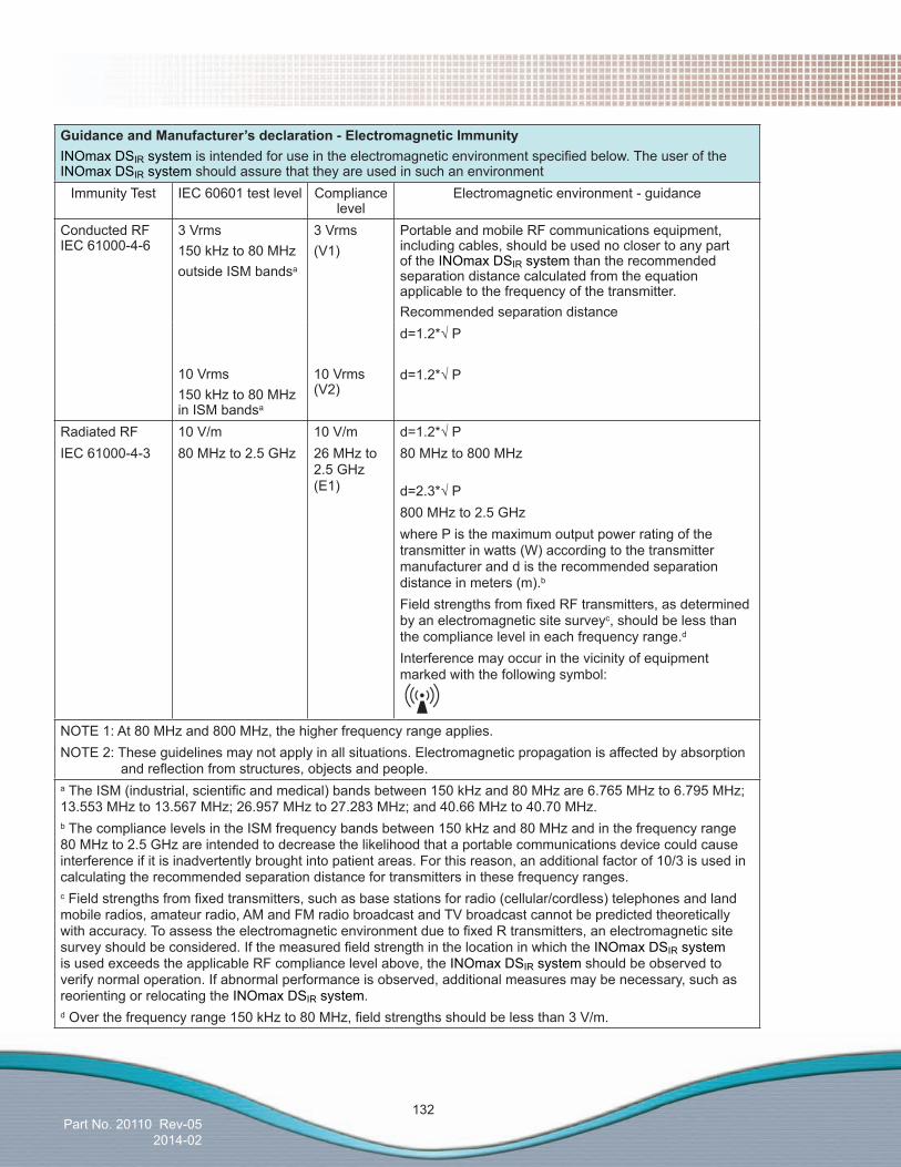
Part No. 20110 Rev-052014-02
132
GuidanceandManufacturer’sdeclaration-ElectromagneticImmunityINOmax DSIR system isintendedforuseintheelectromagneticenvironmentspecifiedbelow.TheuseroftheINOmax DSIR system should assure that they are used in such an environment
Immunity Test IEC 60601 test level Compliance level
Electromagnetic environment - guidance
Conducted RF IEC 61000-4-6
3 Vrms150 kHz to 80 MHzoutside ISM bandsa
10 Vrms150 kHz to 80 MHz in ISM bandsa
3 Vrms(V1)
10 Vrms (V2)
Portable and mobile RF communications equipment, including cables, should be used no closer to any part of the INOmax DSIR system than the recommended separation distance calculated from the equation applicable to the frequency of the transmitter.Recommended separation distanced=1.2*√P
d=1.2*√P
Radiated RFIEC 61000-4-3
10 V/m80 MHz to 2.5 GHz
10 V/m 26 MHz to 2.5 GHz (E1)
d=1.2*√P80 MHz to 800 MHz
d=2.3*√P800 MHz to 2.5 GHzwhere P is the maximum output power rating of the transmitter in watts (W) according to the transmitter manufacturer and d is the recommended separation distance in meters (m).b
FieldstrengthsfromfixedRFtransmitters,asdeterminedby an electromagnetic site surveyc, should be less than the compliance level in each frequency range.d
Interference may occur in the vicinity of equipment marked with the following symbol:
NOTE 1: At 80 MHz and 800 MHz, the higher frequency range applies.NOTE 2: These guidelines may not apply in all situations. Electromagnetic propagation is affected by absorption
andreflectionfromstructures,objectsandpeople.aTheISM(industrial,scientificandmedical)bandsbetween150kHzand80MHzare6.765MHzto6.795MHz;13.553 MHz to 13.567 MHz; 26.957 MHz to 27.283 MHz; and 40.66 MHz to 40.70 MHz.b The compliance levels in the ISM frequency bands between 150 kHz and 80 MHz and in the frequency range 80 MHz to 2.5 GHz are intended to decrease the likelihood that a portable communications device could cause interference if it is inadvertently brought into patient areas. For this reason, an additional factor of 10/3 is used in calculating the recommended separation distance for transmitters in these frequency ranges.cFieldstrengthsfromfixedtransmitters,suchasbasestationsforradio(cellular/cordless)telephonesandlandmobile radios, amateur radio, AM and FM radio broadcast and TV broadcast cannot be predicted theoretically withaccuracy.ToassesstheelectromagneticenvironmentduetofixedRtransmitters,anelectromagneticsitesurveyshouldbeconsidered.IfthemeasuredfieldstrengthinthelocationinwhichtheINOmax DSIR system is used exceeds the applicable RF compliance level above, the INOmax DSIR system should be observed to verify normal operation. If abnormal performance is observed, additional measures may be necessary, such as reorienting or relocating the INOmax DSIR system.dOverthefrequencyrange150kHzto80MHz,fieldstrengthsshouldbelessthan3V/m.

Part No. 20110 Rev-052014-02
133
Recommended separation distances between portable and mobile RF communications equipment and the INOmaxDSIR system
The INOmax DSIR system is intended for use in an electromagnetic environment in which radiated RF disturbances are controlled. The user of the INOmax DSIR system can help prevent electromagnetic interference by maintaining a minimum distance between portable and mobile RF communications equipment (transmitters) and the INOmax DSIR system as recommended below, according to the maximum output power of the communications equipment.
Rated MaximumOutput
Power of Transmitter
W
Separation distance according to frequency of transmitter
m150kHzto80MHz
OutsideISMbands
d=1.2*√ P
150kHzto80MHz
InISMbands
d=1.2*√ P
80MHzto800MHz
d=1.2*√ P
800MHzto2.5GHz
d=2.3*√ P
0.01 0.12 0.12 0.12 0.230.1 0.38 0.38 0.38 0.731 1.2 1.2 1.2 2.310 3.8 3.8 3.8 7.3100 12 12 12 23
For transmitters rated at a maximum output power not listed above, the recommended separation distance d in meters (m) can be estimated using the equation applicable to the frequency of the transmitter, where P is the maximum output power rating of the transmitter in watts (W) according to the transmitter manufacturer.
NOTE 1 At 80 MHz and 800 MHz, the separation distance for the higher frequency range applies.
NOTE 2 These guidelines may not apply in all situations. Electromagnetic propagation is affected by absorptionandreflectionfromstructures,objectsandpeople.
NOTE 3: An additional factor of 10/3 is used in calculating the recommended separation distance for transmitters in the ISM frequency bands between 150 kHz and 80 MHz and in the frequency range 80 MHz to 2.5 GHz to decrease the likelihood that mobile/portable communications equipment could cause interference if it is inadvertently brought into patient areas.
NOTE 4: These guidelines may not apply in all situations. Electromagnetic propagation is affected by absorptionandreflectionfromstructures,objects,andpeople.

Part No. 20110 Rev-052014-02
134
(Intentionally left blank)

Part No. 20110 Rev-052014-02
(Intentionally left blank)
EuropeEuropean Authorized Representative
MDSS GmbHSchiffgraben 41
30175 Hannover, Germany
ManufacturerNorth America
INO Therapeutics LLC d/b/a Ikaria, Inc.Perryville III Corporate Park
53 Frontage Road, Third Floor Hampton, NJ 08827-9001, USA
1-877-566-9466www.ikaria.com
AustraliaAustralia RepresentativeIkaria Australia Pty Ltd.
+61 3 9882 4855
Europe
Part No. 20110 Rev-052014-02