operating instructions for “wdphrh per” … · ec rules(standard ec) normas de la ce direttiva...
TRANSCRIPT
1
OPERATING INSTRUCTIONS FOR “WDPHRH PER” INS T R U M E N T
This manual contains safety information that if ignored can endan-ger life or result in serious injury. They are indicated by this icon.
Keep the instrument protected from sun and water. Avoid water splashes.
Read Carefully ! ENGLISH Version
R1-09-10

2
Danger!
GENERAL SAFETY GUIDELINESIn emergencies the instrument should be switched off immediately! Disconnect the power cable from the power supply!
When installing always observe local regulations!
Manufacturer is not liable for any unauthorized use or misuse of this product that may cause injury,
damage to persons and / or materials.
Caution! Instrument must be accessible at all times for both operating and servicing. Access must not be obstructed in any way!
Feeder should be interlocked with a no-flow protection device to automatically shut-off the peristaltics pumps when there is no flow!
Peristaltics pumps and accessories must be serviced and repaired by qualified and authorized person-nel only!
Always discharge the liquid end before servicing the instrument!
Empty and rinse the liquid end before work on a peristaltic pump which has been used with hazardous or unknown chemicals!
Always read chemical safety datasheet!
Always wear protective clothing when handling hazardous or unknown chemicals!
Instrument must be operated / serviced by trained technicians only!
All connection operations must be performed while the instrument is not connected to main supply!
Adequate measures shall be taken to prevent cross connection of chemicals!
Chemical feeding must be stopped during backwash cycles and periods of noflow as these conditions may introduce the potential for chemical overdosing. Not doing so may result in elevated chemical concentrations and hazerdous gas introduction into the pool or spa.
NORME CEEC RULES(STANDARD EC)NORMAS DE LA CE
Direttiva Basso VoltaggioLow Voltage DirectiveDirectiva de baja tensión
Direttiva EMC Compatibilità ElettromagneticaEMC electromagnetic compatibility directiveEMC directiva de compatibilidad electromagnética
2006/95/CE
2004/108/CE
⎬
⎬

3
1. Introduction
“WDPHRH PER” is a fully Integrated All-in-One Swimming Pool Controller. Ideal for new construction projects the “WDPHRH PER” innovates panel mount capability into a small wall-mount package.
2 Peristaltics pumps for ORP and pH adjustment in PVDF, small-form-factor saves space, installation time, and shipping expense.
It incorporates Input for a Flow Switch. Integral peristaltics pumps, high maintenance tubing sets and roller assemblies.
Working ranges are:
pH : from 0 to 14 pH ORP: from 0 to 999 mV All information are provided through a large LCD display. Using a revolutionary wheel control the instrument can be easily programmed. “WDPHRH PER” is housed in a IP65 plastic box.
2. The wheelLocated in the upper right side of “WDPHRH PER” there is a wheel that must be used to control the instrument. Wheel can be rotated in both directions to scroll over the menus and / or pressed to confirm highlighted selection / value.
NOTE: Once changes are made press “OK” to save and exit from submenu. Press “ESC” to exit without saving.
Rotate wheel to scroll through menus or options
Press wheel to select highlighted option
SCROLL
SELECT

4
Warning: Connections must be perfomed by qualified and trained personnel only.
3. Mainboard Connections
Unplug instrument from main power supply then perform connections to probes and / or selected outputs by following the above picture.
(A) STAND-BY input
(B) FLOW input
(C) pH Level input (left peristaltic pump head)
(D) ORP Level input (right peristaltic pump head)
(E) pH EPHS probe connector
(F) ORP ERHS probe connector
(G) Power Supply: 230VAC 50-60 Hz.
(H) Alarm contact output:
LEFT Peristaltic pump HEAD (pH) RIGHT Peristaltic pump HEAD (ORP)
3 12 4
1 n/a2 Black3 Red4 n/a
(A)
(H)
(D)
(F)
(E)(C)(G)
3 12 4
1 Blue (ground)2 Brown (+)3 n/a4 Black (Signal)
(B)
5
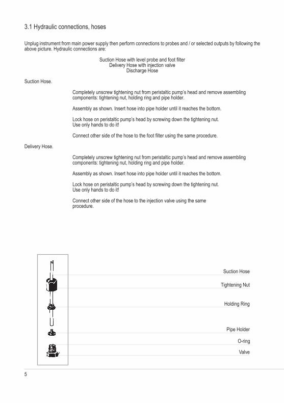
3.1 Hydraulic connections, hoses
Unplug instrument from main power supply then perform connections to probes and / or selected outputs by following the above picture. Hydraulic connections are:
Suction Hose with level probe and foot filterDelivery Hose with injection valve
Discharge Hose
Suction Hose.
Completely unscrew tightening nut from peristaltic pump’s head and remove assembling components: tightening nut, holding ring and pipe holder.
Assembly as shown. Insert hose into pipe holder until it reaches the bottom.
Lock hose on peristaltic pump’s head by screwing down the tightening nut. Use only hands to do it!
Connect other side of the hose to the foot filter using the same procedure.
Delivery Hose.
Completely unscrew tightening nut from peristaltic pump’s head and remove assembling components: tightening nut, holding ring and pipe holder.
Assembly as shown. Insert hose into pipe holder until it reaches the bottom.
Lock hose on peristaltic pump’s head by screwing down the tightening nut. Use only hands to do it!
Connect other side of the hose to the injection valve using the same procedure.
Suction Hose
Tightening Nut
Holding Ring
Pipe Holder
O-ring
Valve
6
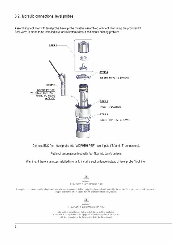
3.2 Hydraulic connections, level probes
Assembling foot filter with level probe.Level probe must be assembled with foot filter using the provided kit. Foot valve is made to be installed into tank’s bottom without sediments priming problem.
Connect BNC from level probe into “WDPHRH PER” level inputs (“B” and “E” connectors).
Put level probe assembled with foot filter into tank’s bottom.
Warning: If there is a mixer installed into tank, install a suction lance instead of level probe / foot filter.
Progettato da Controllato da Modificato da, il Data
Edizione Foglio
/
076.0147.1
Massimo_F 24/10/2003
00
Toll. Gen.`0.05
Materiale:
STEP 5
FILTRO DI ASPIRAZIONE CON SONDA DI LIVELLO - CONTATTO N.O.
FP+CE+PVDF
1 1
STEP 2 INSERT FLOATER
STEP 1 INSERT RING AS SHOWN
STEP 4 INSERT RING AS SHOWN
STEP 3
INSERT PROBEWITH N.O. CONTACT
UNTIL TO HEARA CLICK
WARNINGIF EQUIPMENT IS NOT SUPPLIED WITH A PLUG:
a) a switch or circuit-breaker shall be included in the building installationb) it shall be in close proximity to the equipment and within easy reach of the operator
c) it shall be marked as the disconnetting device for the equipment
WARNINGIF EQUIPMENT IS SUPPLIED WITH A PLUG:
If an appliance coupler or separable plug is used as the disconnecting device, it shall be readily identifiable and easily reached by the operator. For single-phase portable equipment, a plug on a cord of length not greater than 3m is considered to be easily reached.

7
3.3 Hydraulic connections, peristaltic pump heads
Injection Valve.
Injection valve must be installed on plant from water’s input. Injection valve will open at pressure greater than 0,3bar.
Feeder should be interlocked with a no-flow protection device to automatically shut-off the peristaltics pumps when there is no flow!
Adequate measures shall be taken to prevent cross connection of chemicals!
Chemical feeding must be stopped during backwash cycles and periods of noflow as these conditions may introduce the potential for chemical overdosing. Not doing so may result in elevated chemical concentrations and hazerdous gas introduction into the pool or spa.
IN OUT IN OUT
LEFT Peristaltic pump HEAD (pH) RIGHT Peristaltic pump HEAD (ORP)
8
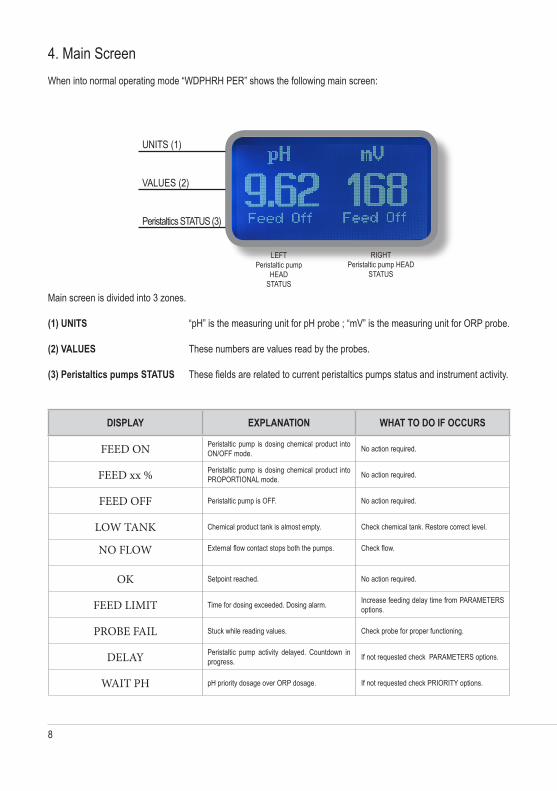
4. Main ScreenWhen into normal operating mode “WDPHRH PER” shows the following main screen:
UNITS (1)
VALUES (2)
Peristaltics STATUS (3)
Main screen is divided into 3 zones.
(1) UNITS “pH” is the measuring unit for pH probe ; “mV” is the measuring unit for ORP probe.
(2) VALUES These numbers are values read by the probes.
(3) Peristaltics pumps STATUS These fields are related to current peristaltics pumps status and instrument activity.
DISPLAY EXPLANATION WHAT TO DO IF OCCURS
FEED ON Peristaltic pump is dosing chemical product into ON/OFF mode. No action required.
FEED xx % Peristaltic pump is dosing chemical product into PROPORTIONAL mode. No action required.
FEED OFF Peristaltic pump is OFF. No action required.
LOW TANK Chemical product tank is almost empty. Check chemical tank. Restore correct level.
NO FLOW External flow contact stops both the pumps. Check flow.
OK Setpoint reached. No action required.
FEED LIMIT Time for dosing exceeded. Dosing alarm. Increase feeding delay time from PARAMETERS options.
PROBE FAIL Stuck while reading values. Check probe for proper functioning.
DELAY Peristaltic pump activity delayed. Countdown in progress. If not requested check PARAMETERS options.
WAIT PH pH priority dosage over ORP dosage. If not requested check PRIORITY options.
LEFTPeristaltic pump
HEAD STATUS
RIGHTPeristaltic pump HEAD
STATUS
9
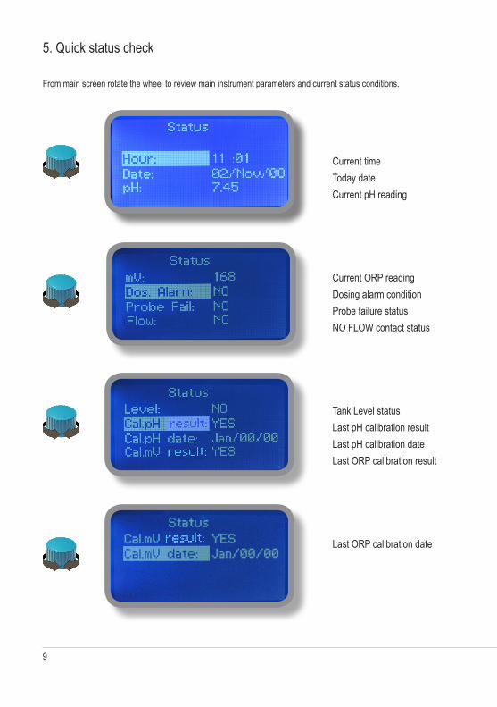
5. Quick status check
From main screen rotate the wheel to review main instrument parameters and current status conditions.
Current timeToday dateCurrent pH reading
Current ORP readingDosing alarm conditionProbe failure statusNO FLOW contact status
Tank Level statusLast pH calibration resultLast pH calibration dateLast ORP calibration result
Last ORP calibration date

10
6. Password
To grant access into “Main Menu” press the wheel from main screen and enter the passcode. If this is the first time here then the passcode is 0000 (factory preset). Press wheel 5 times to enter into “Main Menu”.Otherwise press the wheel 1 time and enter the passcode. Numbers can be selected rotating the wheel.
To set a new passcode choose “PARAMETERS” from “Main Menu” , move on “New Pcode”, Or click on wheel and enter a four numbers code. Or click on “EXIT” and choose “YES” to save request. The new passcode is now ready.
Lost passcode ?
Please dont’ forget the passcode (if changed). In the unfortunate event, please call your local distributor for unlocking procedure. There is no way for you to recover lost passcode.
X5
11
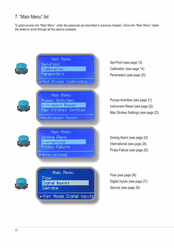
7. “Main Menu” listTo grant access into “Main Menu” enter the passcode (as described in previous chapter). Once into “Main Menu” rotate the wheel to scroll through all the options available.
Set-Point (see page 12)Calibration (see page 14)Parameters (see page 20)
Pumps Activities (see page 21)Instrument Reset (see page 22)Max Strokes Settings (see page 22)
Dosing Alarm (see page 23)International (see page 24)Probe Failure (see page 25)
Flow (see page 26)Digital Inputs (see page 27)Service (see page 26)

12
8. “Set-Point”, pH (on/off)
pH reading values can be set to operate the pH peristaltic pump using 2 set-points into On/Off mode or Proportional (%).
On/Off mode set the instrument to operate using two set values that enable or disable the pH peristaltic pump. To use this mode move cursor on “Working Mode”. Press the wheel and select it.
ON/OFF mode while dosing ALKALISet pH value at 7.00 OFF and 6.90 ON.Instrument will leave the pH peristaltic pump active until reading value will increase up to 7.00pH. At 7.00pH the pH peristaltic pump will be disabled until reading value will decrease under 6.90pH.
6.90 7.00
ON
OFF
13
8. “Set-Point”, pH (on/off)
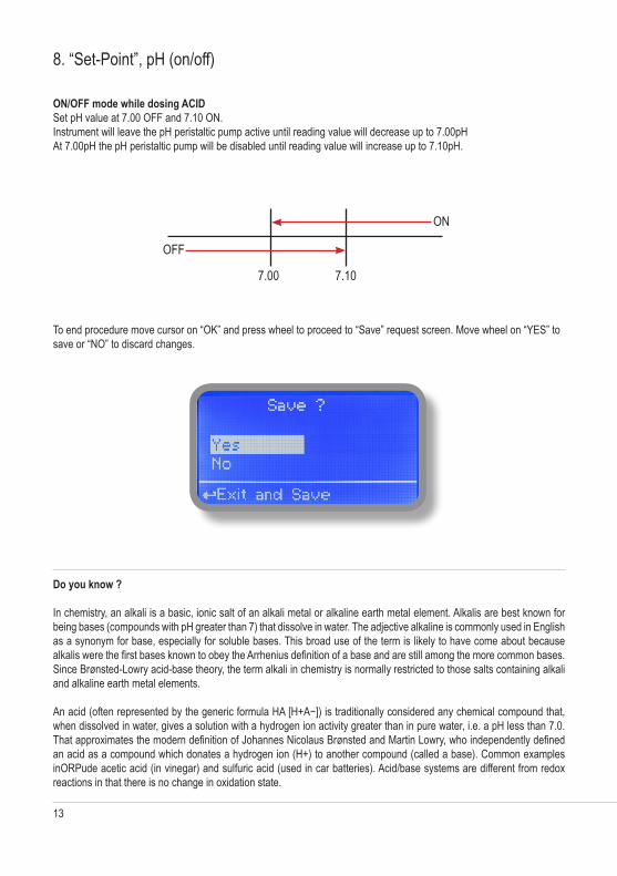
ON/OFF mode while dosing ACIDSet pH value at 7.00 OFF and 7.10 ON.Instrument will leave the pH peristaltic pump active until reading value will decrease up to 7.00pHAt 7.00pH the pH peristaltic pump will be disabled until reading value will increase up to 7.10pH.
To end procedure move cursor on “OK” and press wheel to proceed to “Save” request screen. Move wheel on “YES” to save or “NO” to discard changes.
Do you know ?
In chemistry, an alkali is a basic, ionic salt of an alkali metal or alkaline earth metal element. Alkalis are best known for being bases (compounds with pH greater than 7) that dissolve in water. The adjective alkaline is commonly used in English as a synonym for base, especially for soluble bases. This broad use of the term is likely to have come about because alkalis were the first bases known to obey the Arrhenius definition of a base and are still among the more common bases. Since Brønsted-Lowry acid-base theory, the term alkali in chemistry is normally restricted to those salts containing alkali and alkaline earth metal elements.
An acid (often represented by the generic formula HA [H+A−]) is traditionally considered any chemical compound that, when dissolved in water, gives a solution with a hydrogen ion activity greater than in pure water, i.e. a pH less than 7.0. That approximates the modern definition of Johannes Nicolaus Brønsted and Martin Lowry, who independently defined an acid as a compound which donates a hydrogen ion (H+) to another compound (called a base). Common examples inORPude acetic acid (in vinegar) and sulfuric acid (used in car batteries). Acid/base systems are different from redox reactions in that there is no change in oxidation state.
7.00 7.10
ON
OFF
14
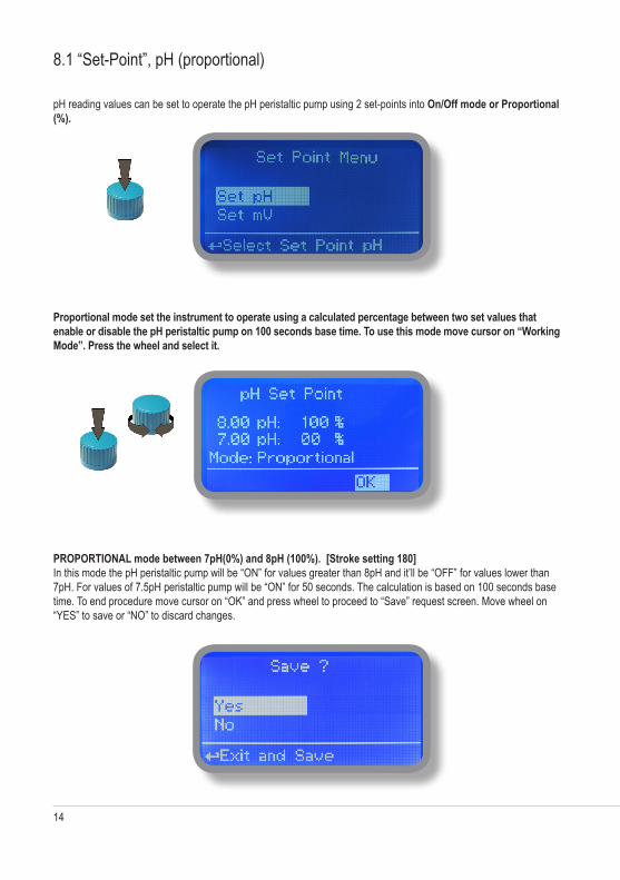
8.1 “Set-Point”, pH (proportional)
pH reading values can be set to operate the pH peristaltic pump using 2 set-points into On/Off mode or Proportional (%).
Proportional mode set the instrument to operate using a calculated percentage between two set values that enable or disable the pH peristaltic pump on 100 seconds base time. To use this mode move cursor on “Working Mode”. Press the wheel and select it.
PROPORTIONAL mode between 7pH(0%) and 8pH (100%). [Stroke setting 180]In this mode the pH peristaltic pump will be “ON” for values greater than 8pH and it’ll be “OFF” for values lower than 7pH. For values of 7.5pH peristaltic pump will be “ON” for 50 seconds. The calculation is based on 100 seconds base time. To end procedure move cursor on “OK” and press wheel to proceed to “Save” request screen. Move wheel on “YES” to save or “NO” to discard changes.
15
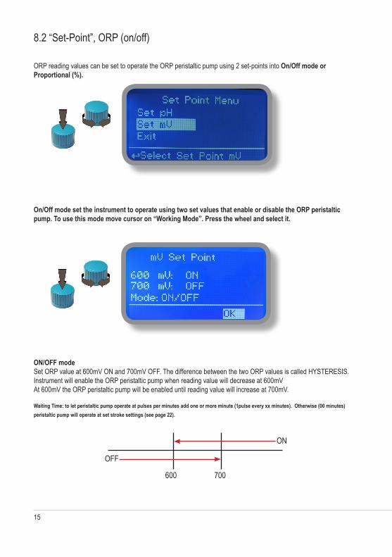
8.2 “Set-Point”, ORP (on/off)
ORP reading values can be set to operate the ORP peristaltic pump using 2 set-points into On/Off mode or Proportional (%).
On/Off mode set the instrument to operate using two set values that enable or disable the ORP peristaltic pump. To use this mode move cursor on “Working Mode”. Press the wheel and select it.
ON/OFF modeSet ORP value at 600mV ON and 700mV OFF. The difference between the two ORP values is called HYSTERESIS.Instrument will enable the ORP peristaltic pump when reading value will decrease at 600mVAt 600mV the ORP peristaltic pump will be enabled until reading value will increase at 700mV.
Waiting Time: to let peristaltic pump operate at pulses per minutes add one or more minute (1pulse every xx minutes). Otherwise (00 minutes) peristaltic pump will operate at set stroke settings (see page 22).
600 700
ON
OFF
16
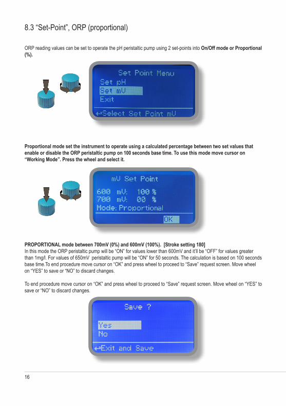
8.3 “Set-Point”, ORP (proportional)
ORP reading values can be set to operate the pH peristaltic pump using 2 set-points into On/Off mode or Proportional (%).
Proportional mode set the instrument to operate using a calculated percentage between two set values that enable or disable the ORP peristaltic pump on 100 seconds base time. To use this mode move cursor on “Working Mode”. Press the wheel and select it.
PROPORTIONAL mode between 700mV (0%) and 600mV (100%). [Stroke setting 180]In this mode the ORP peristaltic pump will be “ON” for values lower than 600mV and it’ll be “OFF” for values greater than 1mg/l. For values of 650mV peristaltic pump will be “ON” for 50 seconds. The calculation is based on 100 seconds base time.To end procedure move cursor on “OK” and press wheel to proceed to “Save” request screen. Move wheel on “YES” to save or “NO” to discard changes.
To end procedure move cursor on “OK” and press wheel to proceed to “Save” request screen. Move wheel on “YES” to save or “NO” to discard changes.

17
9. “Probe Calibration”, pH
pH calibration procedure involves two calibration points and it requires two buffer solutions. Default buffer solutions are pH 4.00 and pH 7.00. pH reading value can be also 30°C temperature compensated from “pH compensation” menu. From “Menu Calibration” choose “pH probe”.
In the following example instrument will calibrate pH using default buffer solutions values.
Note: this procedure assumes that instrument is correctly configured and a working pH probe connected. Otherwise unattended results may occurr.
Calib 1st Point.
Once into “pH Calibration” menu move wheel on “P1” then press wheel to enter into first point calibration submenu. Prepare 7.00pH buffer solution and dip probe’s sensor on it. Wait until reading value is stable and according to buffer solution value move wheel until it is the same on display (“Cal. at” field). Default value is 7.00pH. To end procedure move cursor on “OK” and press wheel to proceed to next step.
Note: buffer solution value may change if environment temperature it’s different than 20°C. Read solution’s label for more information. According to this occurrence “pH Default” must be changed.
pH7

18
9. “Probe Calibration”, pH
Calib 2nd Point.
Move wheel on “P2” then press wheel to enter into second point calibration submenu. Prepare 4.00pH buffer solution and dip probe’s sensor on it. Wait until reading value is stable and according to buffer solution value move wheel until it is the same on display (“Cal. at” field). Default value is 4.00pH.
To end procedure move cursor on “OK” and press wheel to proceed to “Save” request screen. Move wheel on “YES” to save or “NO” to discard changes.
Note: buffer solution value may change if environment temperature it’s different than 20°C. Read solution’s label for more information. According to this occurrence “pH Default” must be changed.
pH4
19
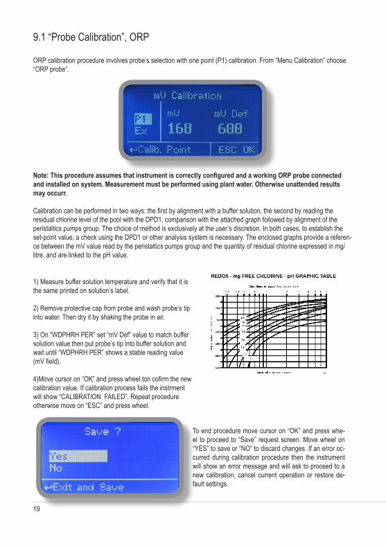
9.1 “Probe Calibration”, ORP
ORP calibration procedure involves probe’s selection with one point (P1) calibration. From “Menu Calibration” choose “ORP probe”.
Note: This procedure assumes that instrument is correctly configured and a working ORP probe connected and installed on system. Measurement must be performed using plant water. Otherwise unattended results may occurr.
Calibration can be performed in two ways: the first by alignment with a buffer solution, the second by reading the residual chlorine level of the pool with the DPD1, comparison with the attached graph followed by alignment of the peristaltics pumps group. The choice of method is exclusively at the user’s discretion. In both cases, to establish the set-point value, a check using the DPD1 or other analysis system is necessary. The enclosed graphs provide a referen-ce between the mV value read by the peristaltics pumps group and the quantity of residual chlorine expressed in mg/litre, and are linked to the pH value.
To end procedure move cursor on “OK” and press whe-el to proceed to “Save” request screen. Move wheel on “YES” to save or “NO” to discard changes. If an error oc-curred during calibration procedure then the instrument will show an error message and will ask to proceed to a new calibration, cancel current operation or restore de-fault settings.
1) Measure buffer solution temperature and verify that it is the same printed on solution’s label.
2) Remove protective cap from probe and wash probe’s tip into water. Then dry it by shaking the probe in air.
3) On “WDPHRH PER” set “mV Def” value to match buffer solution value then put probe’s tip into buffer solution and wait until “WDPHRH PER” shows a stable reading value (mV field).
4)Move cursor on “OK” and press wheel ton cofirm the new calibration value. If calibration process fails the instrment will show “CALIBRATION FAILED”. Repeat procedure otherwise move on “ESC” and press wheel.

20
10. “Parameters”
From “Menu Calibration” choose “Parameters”. This menu allows to set a delay (max 60 minutes) before peristaltics pumps begin to feed. Furthermore use this menu to set pH peristaltic pump startup priority and to change default passcode.
Feeding Delay.
Move on “Feeding Delay” then press wheel. Choose a value between 0 (disabled) and 60 minutes (maximum delay time). This feature can be used to accord a startup delay for the peristaltics pumps. Delay occurs when instrument is powered or after a “NO FLOW” contact recovery.
Mode.
Move on “Mode” then press wheel. If both peristaltics pumps need to operate, a startup priority can be set to allow the pH peristaltic pump to begin to feed prior to ORP peristaltic pump. Choose “pH priority” to enable this function. ORP peristaltic pump will begin to dose when pH peristaltic pump has stopped.
New Pcode.
See page 10.
To end procedure move cursor on “OK” and press wheel to proceed to “Save” request screen. Move wheel on “YES” to save or “NO” to discard changes.

21
11. “Peristaltics pumps Activities”
From “Menu Calibration” choose “Peristaltics pumps activities”. This menu allows to manually operate one or both the peristaltics pumps for a settable time.
Move on “Mode” then press wheel. Choose “Man. Peristaltic pump1” for manually operate pH peristaltics pumps or “Man. Peristaltic pump2” for ORP peristaltic pump.
Press wheel to move cursor on “TIME” field. Once here, choose a working time between 0 (disabled) or 199 minutes. Move on “EXIT”, then press wheel.
Choose “YES” to save changes. Exit from main menu. Main display will show a countdown including the selected peri-staltic pump (left for pH peristaltic pump, right for ORP peristaltic pump). To stop this countdown go back to “Peristaltic pump activities” menu and choose “ON” as working mode or wait until countdown ends. This function can be used for priming purposes.

22
11. “Instrument Reset”
To restore instrument to its default values (including password) once into “Instrument Reset” menu, press wheel then change value to “ON”, press wheel again, move on “OK” then finally press wheel. The instrument display will show “CHECKSUM ERROR”. Press whell to return into “Main Menu”. Move on “EXIT”, then press wheel. The instrument is now restored to factory default. Please repeat all calibration procedures and programming parameters.
23
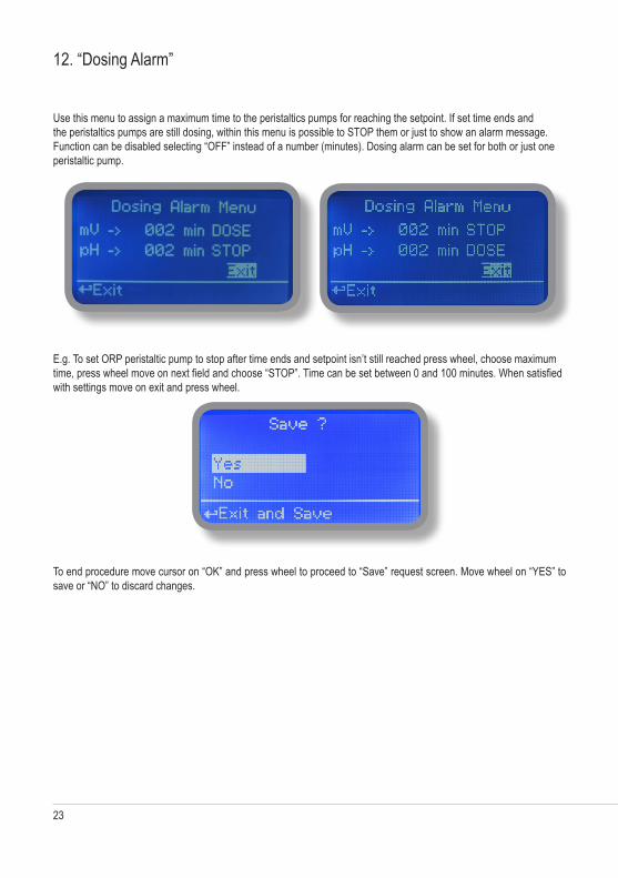
12. “Dosing Alarm”
Use this menu to assign a maximum time to the peristaltics pumps for reaching the setpoint. If set time ends and the peristaltics pumps are still dosing, within this menu is possible to STOP them or just to show an alarm message. Function can be disabled selecting “OFF” instead of a number (minutes). Dosing alarm can be set for both or just one peristaltic pump.
E.g. To set ORP peristaltic pump to stop after time ends and setpoint isn’t still reached press wheel, choose maximum time, press wheel move on next field and choose “STOP”. Time can be set between 0 and 100 minutes. When satisfied with settings move on exit and press wheel.
To end procedure move cursor on “OK” and press wheel to proceed to “Save” request screen. Move wheel on “YES” to save or “NO” to discard changes.
24
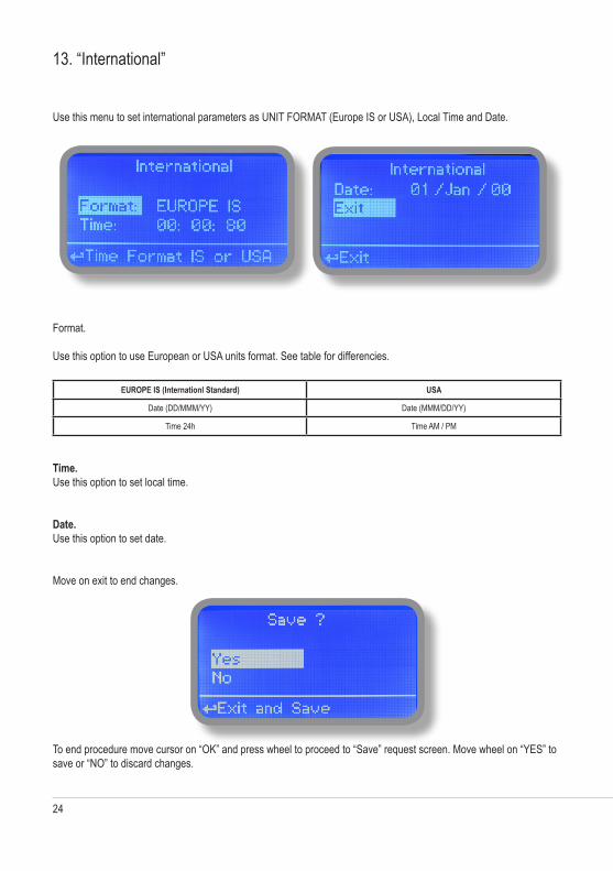
13. “International”
Use this menu to set international parameters as UNIT FORMAT (Europe IS or USA), Local Time and Date.
Format.
Use this option to use European or USA units format. See table for differencies.
EUROPE IS (Internationl Standard) USA
Date (DD/MMM/YY) Date (MMM/DD/YY)
Time 24h Time AM / PM
Time.Use this option to set local time.
Date.Use this option to set date.
Move on exit to end changes.
To end procedure move cursor on “OK” and press wheel to proceed to “Save” request screen. Move wheel on “YES” to save or “NO” to discard changes.
25
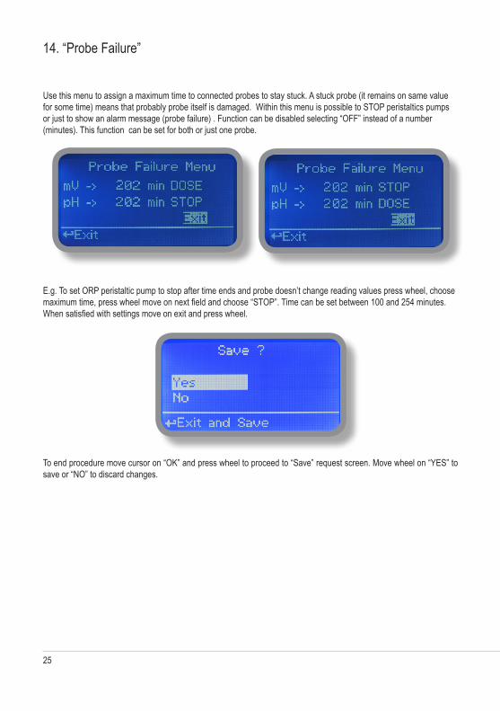
14. “Probe Failure”
Use this menu to assign a maximum time to connected probes to stay stuck. A stuck probe (it remains on same value for some time) means that probably probe itself is damaged. Within this menu is possible to STOP peristaltics pumps or just to show an alarm message (probe failure) . Function can be disabled selecting “OFF” instead of a number (minutes). This function can be set for both or just one probe.
E.g. To set ORP peristaltic pump to stop after time ends and probe doesn’t change reading values press wheel, choose maximum time, press wheel move on next field and choose “STOP”. Time can be set between 100 and 254 minutes. When satisfied with settings move on exit and press wheel.
To end procedure move cursor on “OK” and press wheel to proceed to “Save” request screen. Move wheel on “YES” to save or “NO” to discard changes.

26
15. “Flow Contact”
Flow contact (locate connection on page 4) can be enabled to stop all dosing activities using a DIRECT contact (N.O. normally opened contact) or REVERSE contact (N.C. normally closed contact). Move wheel for enabling and changing contact logic (DIRECT or REVERSE).
To end procedure move cursor on “OK” and press wheel to proceed to “Save” request screen. Move wheel on “YES” to save or “NO” to discard changes.
16. “Service”
This “view only” menu shows probes reading live. Press “ESC” to exit.
27
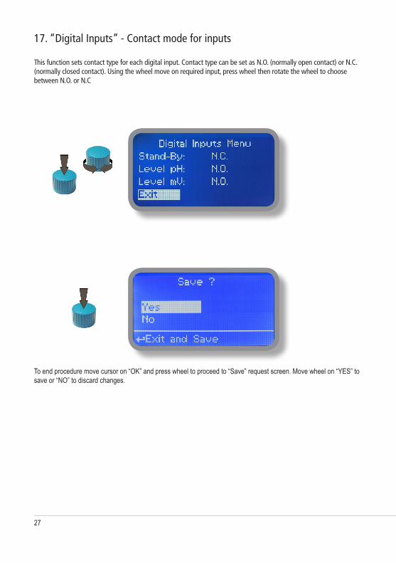
17. “Digital Inputs” - Contact mode for inputs
This function sets contact type for each digital input. Contact type can be set as N.O. (normally open contact) or N.C. (normally closed contact). Using the wheel move on required input, press wheel then rotate the wheel to choose between N.O. or N.C
To end procedure move cursor on “OK” and press wheel to proceed to “Save” request screen. Move wheel on “YES” to save or “NO” to discard changes.
28
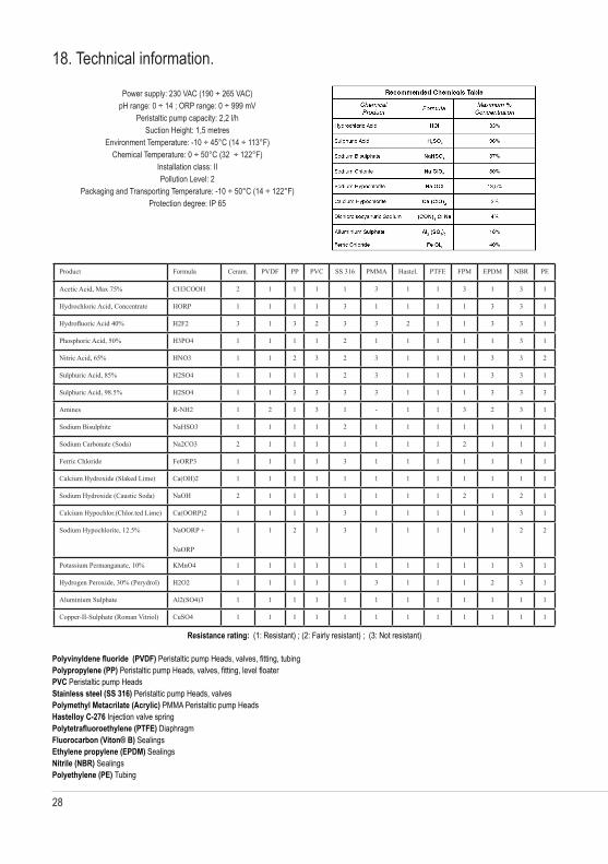
18. Technical information.
Resistance rating: (1: Resistant) ; (2: Fairly resistant) ; (3: Not resistant)
Polyvinyldene fluoride (PVDF) Peristaltic pump Heads, valves, fitting, tubing Polypropylene (PP) Peristaltic pump Heads, valves, fitting, level floater PVC Peristaltic pump Heads Stainless steel (SS 316) Peristaltic pump Heads, valves Polymethyl Metacrilate (Acrylic) PMMA Peristaltic pump Heads Hastelloy C-276 Injection valve spring Polytetrafluoroethylene (PTFE) Diaphragm Fluorocarbon (Viton® B) SealingsEthylene propylene (EPDM) SealingsNitrile (NBR) SealingsPolyethylene (PE) Tubing
Product Formula Ceram. PVDF PP PVC SS 316 PMMA Hastel. PTFE FPM EPDM NBR PE
Acetic Acid, Max 75% CH3COOH 2 1 1 1 1 3 1 1 3 1 3 1
Hydrochloric Acid, Concentrate HORP 1 1 1 1 3 1 1 1 1 3 3 1
Hydrofluoric Acid 40% H2F2 3 1 3 2 3 3 2 1 1 3 3 1
Phosphoric Acid, 50% H3PO4 1 1 1 1 2 1 1 1 1 1 3 1
Nitric Acid, 65% HNO3 1 1 2 3 2 3 1 1 1 3 3 2
Sulphuric Acid, 85% H2SO4 1 1 1 1 2 3 1 1 1 3 3 1
Sulphuric Acid, 98.5% H2SO4 1 1 3 3 3 3 1 1 1 3 3 3
Amines R-NH2 1 2 1 3 1 - 1 1 3 2 3 1
Sodium Bisulphite NaHSO3 1 1 1 1 2 1 1 1 1 1 1 1
Sodium Carbonate (Soda) Na2CO3 2 1 1 1 1 1 1 1 2 1 1 1
Ferric Chloride FeORP3 1 1 1 1 3 1 1 1 1 1 1 1
Calcium Hydroxide (Slaked Lime) Ca(OH)2 1 1 1 1 1 1 1 1 1 1 1 1
Sodium Hydroxide (Caustic Soda) NaOH 2 1 1 1 1 1 1 1 2 1 2 1
Calcium Hypochlor.(Chlor.ted Lime) Ca(OORP)2 1 1 1 1 3 1 1 1 1 1 3 1
Sodium Hypochlorite, 12.5% NaOORP +
NaORP
1 1 2 1 3 1 1 1 1 1 2 2
Potassium Permanganate, 10% KMnO4 1 1 1 1 1 1 1 1 1 1 3 1
Hydrogen Peroxide, 30% (Perydrol) H2O2 1 1 1 1 1 3 1 1 1 2 3 1
Aluminium Sulphate Al2(SO4)3 1 1 1 1 1 1 1 1 1 1 1 1
Copper-II-Sulphate (Roman Vitriol) CuSO4 1 1 1 1 1 1 1 1 1 1 1 1
Power supply: 230 VAC (190 ÷ 265 VAC) pH range: 0 ÷ 14 ; ORP range: 0 ÷ 999 mV
Peristaltic pump capacity: 2,2 l/hSuction Height: 1,5 metres
Environment Temperature: -10 ÷ 45°C (14 ÷ 113°F)Chemical Temperature: 0 ÷ 50°C (32 ÷ 122°F)
Installation class: IIPollution Level: 2
Packaging and Transporting Temperature: -10 ÷ 50°C (14 ÷ 122°F)Protection degree: IP 65

29
19. Dimensions & Chemical concentrations
mm [inches]
36
Terra Terra
Stand-B
y
FUS
E
FUS
E
LN
230Vac
PT100
RS
232
RS
485
RH
FLOW
Brow
n
Blue
Black
Level:pH
Level: OR
P
N.C
.
Earth
Earth
Earth
Earth
Earth
Earth
Earth
Earth
pHP
robe
pHS
olenoidS
olenoid
Alarm
Output
(Contact)
Temperature
Probe
Serial
28. Board connections
Information on this manual may contain technical inaccuracies or typographical errors.The information contained may be changed at any time without prior notification or obligation.
F2
pH / ORP Probe connection module

30
20. Installation draw
Information on this manual may contain technical inaccuracies or typographical errors.The information contained may be changed at any time without prior notification or obligation.

31
21. Index
CE Conformity DeORParation page 2General Safety Guidelines page 2
Introduction page 3The wheel page 3
Mainboard connections page 4Hydraulic connections, hoses page 5Hydraulic connections, level probes page 6Hydraulic connections, peristaltic pump page 7Main screen page 8Quick status check page 9Password page 10
“Main menu” list page 11“Set point” pH (ON/OFF) page 12“Set point” pH (Proportional) page 14“Set point”, ORP (ON/OFF) page 15“Set point”, ORP (Proportional) page 16“Probe Calibration”, pH page 17“Power Supply Calibration” page 17“Probe Calibration”, ORP page 19“Parameters” page 20“Peristaltic pump Activities” page 21“Instrument Reset” page 22“Dosnig Alarm” page 23“International” page 24“Probe Failure” page 25“pH Compensation” page 26“Flow” page 26“Service” page 26“Digital Inputs” page 27Technical Information page 28Dimensions and board connections page 29Index page 31

MAURIZIO MANCINI, Presidente EMEC S.r.l.
Via Donatori di sangue, 1 - 02100 Rieti - ItalyTel. +39 0746 2284 1 - Tel. +39 0746 1725114 - Fax +39 0746 2284 2 -
[email protected] - www.emec.it
DECLARATION OF CONFORMITY
The Company EMEC s.r.l.
Company Address Via Donatori di Sangue 1 - 02100 RIETI - ITALIA
DECLARES under its own responsibility, that the product
Description: Diaphragm metering pump, series Vxx Serial no.: refer to the nameplate on the device
complies to the following standards:
EC RULES (STANDARD EC) Low Voltage Directive (2006/95/CE) EMC electromagnetic compatibility directive (2006/42/CE)
EUROPEAN HARMONIZED STANDARDS UNDER DIRECTIVE EN 12100-1, EN 12100-2, Safety of Machinery EN 809, Pumps and pumping units for liquids-Safety requirements UNI 10637, Measuring instruments for temperature, pH, ORP, free and combined chlorine and the isocyanuric acid are within the requirements of standard UNI 10637. D.M. 7 February 2012 n.25 – D.M. 6 April 2004 n. 174 – Regulation EU 10/2011- Equipment intended to come into contact with food.
The product passed the final test.
Date: 14/06/2012
Signature

MAURIZIO MANCINI, Presidente EMEC S.r.l.
Via Donatori di sangue, 1 - 02100 Rieti - ItalyTel. +39 0746 2284 1 - Tel. +39 0746 1725114 - Fax +39 0746 2284 2 -
[email protected] - www.emec.it
DICHIARAZIONE DI CONFORMITà
La società EMEC s.r.l.
con indirizzo Via Donatori di Sangue 1 - 02100 RIETI - ITALIA
DICHIARA sotto la propria responsabilità, che il prodotto
Descrizione: pompa dosatrice a membrana, serie Vxx Seriale n.: fare riferimento all’etichetta riportata sul prodotto
è conforme alle seguenti norme:
NORME CE Direttiva Basso Voltaggio (2006/95/CE) Direttiva EMC Compatibilità Elettromagnetica (2006/42/CE)
NORME ARMONIZZATE EUROPEE NELL’AMBITO DELLA DIRETTIVA EN 12100-1, EN 12100-2, Sicurezza sul macchinario EN 809, Pompe e gruppi di pompaggio per liquidi - Requisiti di sicurezza UNI 10637, Gli strumenti di misura per la temperatura, il pH, il potenziale redox, il cloro attivo libero, il cloro attivo combinato e l’acido isocianurico rientrano nei requisiti della norma UNI 10637. D.M. 7 febbraio 2012 n.25 – D.M. 6 Aprile 2004 n. 174 – Reg. UE 10/2011 - Apparecchiature finalizzate al trattamento dell’acqua destinata al consumo umano
Il prodotto ha superato il collaudo finale.
Data: 14/06/2012
Firma:
MAURIZIO MANCINI, Presidente EMEC S.r.l.
Via Donatori di sangue, 1 - 02100 Rieti - ItalyTel. +39 0746 2284 1 - Tel. +39 0746 1725114 - Fax +39 0746 2284 2 -
[email protected] - www.emec.it
DéCLARATION DE CONFORMITé
La societé EMEC s.r.l.
usine de production Via Donatori di Sangue 1 - 02100 RIETI - ITALIA
DéCLARE que le produit mentionné ci-dessous
Description: pompe doseuse , serie Vxx Série n.: veuillez Reportez-vous à l’étiquette du produit
est conforme aux normes suivantes:
NORME CE Directive sur les basses tension (2006/95/CE) Directive sur la compatibilité électromagnétique (2006/42/CE)
NORMES EUROPéENNES HARMONISéES EN 12100-1, EN 12100-2, Sécurité des machines EN 809, Pompes et groupes motopompes pour liquides - Pompes et groupes motopompes pour liquides UNI 10637, Le notre systèmes de contrôle de température, pH, Redox, Chlore active libre et combinée et l‘acide hypochloreux sont conformes avec UNI 10637 D.M. 7 febbraio 2012 n.25 – D.M. 6 Aprile 2004 n. 174 – Règlement (UE) n° 10/2011 de la Commission du 14 janvier 2011 concernant les matériaux et objets en matière plastique destinés à entrer en contact avec des denrées alimentaires
Le produit a passé le test final.
Date: 14/06/2012
Signé:
MAURIZIO MANCINI, Presidente EMEC S.r.l.
Via Donatori di sangue, 1 - 02100 Rieti - ItalyTel. +39 0746 2284 1 - Tel. +39 0746 1725114 - Fax +39 0746 2284 2 -
[email protected] - www.emec.it
DECLARACIÓN DE CONFORMIDAD
Sociedad EMEC s.r.l.
Dirección de la empresa Via Donatori di Sangue 1 - 02100 RIETI - ITALIA
DECLARA bajo su responsabilidad, que el producto
Description: bombas de membrane serie de Vxx Serial nombre: Consulte la etiqueta de producto
Se ajustan a las normas seguientes:
NORMAS DE LA CE Directiva de baja tensión (2006/95/CE) EMC directiva de compatibilidad electromagnética (2004/108/CE)
NORMAS EUROPEAS ARMONIZADAS CONFORME A LA DIRECTIVA EN 12100-1, EN 12100-2, Seguridad de las màquinas EN 809, Bombas y unidades de bombeo para liquidos-los requisitos de seguridad UNI 10637, Instrumentos de medición de temperatura, pH, potencial redox, cloro activo libre, cloro combinado y el ácido isocianúrico están dentro de los requisitos de la norma UNI 10637. Reglamento (UE) nº 10/2011 de la Comisión, de 14 de enero de 2011, sobre materiales y objetos plásticos destinados a entrar en contacto con alimentos.
El producto ha superado la prueba final.
Data: 14/06/2012
Fecha:
32
When dismantling this instrument please separate material types and send them according to local recyORPing disposal requirements.We appreciate your efforts in supporting your local RecyORPe Environmental Program.
Working together we’ll form an active union to assure the world’s invaluable resources are conserved.