operating instructions explosion protected scales for ... · operating instructions combics caixs2...
TRANSCRIPT

98648-019-74
98648-019-74
Operating Instructions
Sartorius Combics 2 Ex Indicator for Use in Areas at Risk to Explosion
Model CAIXS2
Order no. Price in €
CAIXS2 1.500
Preconfiguration with platform series CAPXS, IU, IF; verification by the manufacturer; calibration for the place of use;
mounting optional dataoutputs;
removable connection between terminal and platform can be ordered under VF2829. Please ask your sales representative.
• Networking of up to 8 indicators
• Suitable for: mounting on a bench, attaching to floor stand or columns,
mounting on a wall or installation in a switch cabinetCombics 2 Ex-Indikator
Description
Combics 2 Ex-Indicator
Stainless steel housing with cable glance.
Selectable is an A/D converter or digital interface to connect one scale in total.
Standard: 1 selectable data interface RS 232/485/422
Pre-assembled adapter cable for power supply modules.
The power supply for CAIXS2 is not included in the equipment supplied (see accessories).
Explosion protected scales for hazardous areas - Combics Ex-Indicator CAIXS2
• For use in Zones 1 (explosive gases) and Zone 21 (explosive dusts)
• ATEX: II 2G Ex ia IIC T4 Gb
II 2D Ex ia IIIC T80°C Db
• Allows the connection of one analogue Sartorius platforms Combics-Ex,
IFXS4, IUXS4, or one IS-X precision platforms, Signum Ex scale or load
cells with suitable specifications to be connected in Zone 1, 21, 20
• Verifiable class III, IIII
• Very easy to read display

2 Operating Instructions Combics CAIXS2
Contents
ContentsNotes on Using these Instructions ..................................... 3Warnings and Safety Precautions ............................................. 4Device Description ............................................................... 5
Intended Use ................................................................................. 5General View of the Equipment ............................................. 6
Installation ............................................................................ 7Getting Started .................................................................................. 8
Connecting a Weighing Platform ......................................... 9Pin Assignment Chart ...............................................................11Connecting the Device to AC Power ....................................12
Operating Design ..............................................................................13Key Functions ..............................................................................14Stored Settings ...........................................................................15Applying the Tare Weight .......................................................15Display ...........................................................................................16Menu Operating Design ...........................................................17Configuration ..............................................................................19Setting up Password Protection .........................................20
Configuring Weighing Platforms ..............................................23Service Mode ...............................................................................22Analog/Digital Converter (ADC) ............................................24Configuring an ADC ..................................................................28Geographical Data .....................................................................29Entering Adjustment and Linearization Weights .............31Function Allocation of the J Key ............................. 31External Linearization ...............................................................32Setting the Preload ...................................................................33Deleting the Preload .................................................................34Adjustment without Weights .................................................35
Operation .............................................................................. 36Weighing .......................................................................................36Adjustment/Configuration Counter .............................. 38Device Parameters .......................................................... 39Calibration, Adjustment................................................. 43SQmin Function ............................................................. 46Data ID Codes ..............................................................................48Application Programs ...............................................................50Counting Z .................................................................................51Neutral MeasurementZ nM ........................................ 56Averaging (Animal Weighing) V ............................... 60Weighing in PercentL .................................................. 64Checkweighing H ......................................................... 69Classification W ............................................................ 77Totalizings .................................................................... 82Net Total Formulation R ............................................ 86Combining Application Programs .........................................90Configuring Printouts ...............................................................93Product Data Memory ..............................................................97
Data Interfaces ..................................................................... 99Communications Interface Configuration .................100Data Input Format .......................................................101Printer Interface Configuration (Printer) ...............103Configuring a Printout ................................................105GMP-Compliant Printouts .........................................106Sample Printouts ..........................................................108
Error Messages ...................................................................111Care and Maintenance ......................................................112
Service ........................................................................................ 112Repairs ........................................................................................ 112Cleaning ..................................................................................... 112Safety Inspection .................................................................... 113Disposal ...................................................................................... 114
Specifications ..................................................................... 115Dimensions (Scale Drawings)............................................ 116Accessories ..........................................................................117Declaration of Conformity ..................................................119
Declaration of Conformity ................................................... 120EC Type Approval Certificate ............................................... 122Test Certificate ......................................................................... 123Ex Safety Notes ........................................................................ 124
Menu Structure ..................................................................126External Data Interface ......................................................... 142Verification of Intrinsic Safety ........................................... 147
General Password ...............................................................153

Operating Instructions Combics CAIXS2 3
Notes on Using These Instructions
Notes on Using These Instructionst Please read these instructions carefully and completely before using,
maintaining or repairing the device.t Observe the safety instructions.t These instructions are part of the product. Keep it in a safe and easily accessible
location.t If the instructions should be lost or misplaced, please contact Sartorius
for a replacement or download the latest version from our website: www.sartorius.com
Symbols and SignsThe following symbols are used in this manual:
3 Warning symbol for various types of dangers.
h This symbol indicates useful information and tips.
e, 1, This and similar symbols mean that the respective key should be pressed.
T T ..., This means that this key must be pressed more than once.
t Indicates a required actiony Describes the result of an action1. If a procedure has multiple steps... 2. ... the steps are numbered consecutively– Indicates an item in a list
Menu DescriptionsIn some cases, text descriptions are used to describe menu settings and in other cases only the number structure of the menu is used for faster orientation for experienced users (e.g. “Menu item 1.9« contains the parameter settings for calibration/adjustment). The Setup menu is shown on the display when “codes” is selected as the language.
h Technical advice/hotline:
Phone: +49 (0) 40 / 67960444 Fax: +49 (0) 40 / 67960474
E-mail: [email protected]

4 Operating Instructions Combics CAIXS2
Warnings and Safety Precautions
Warnings and Safety PrecautionsThe Combics CAIXS2 indicator complies with the European Council Directives as well as international regulations and standards for electrical equipment, electromagnetic compatibility, and the stipulated safety requirements. Improper use or handling, however, can result in damage and/or injury.
t Read these operating instructions carefully before use. This will prevent damage to the equipment. Please observe safety instructions 65015-750-16 in the safety information section. Please also bear the following points in mind:
3 Make absolutely sure to unplug the indicator from the power before you connect or disconnect any electronic peripheral devices to or from the interface port.
3 If you use electrical equipment in installations and under ambient conditions requiring higher safety standards, you must comply with the provisions as specified in the applicable regulations for installation in your country.
3 The operator shall be responsible for any modifications to the equipment and for any connections of cables or equipment not supplied by Sartorius and must check and, if necessary, correct these modifications and connections. Warning when using RS-232 cables, purchased from other manufacturers: These often have incorrect pin assignments for use with Sartorius equipment. Connect only Sartorius accessories and options, since these are optimally designed for use with your device. Therefore, do not use any proprietary solutions. The operator shall be solely responsible for installation and testing of any modifications to Sartorius equipment, including connection of cables or equipment not supplied by Sartorius. Information on operational quality (in line with norms pertaining to immunity) is available on request.
3 Clean your equipment only as directed in the cleaning instructions (see “Care and Maintenance").
3 The display value can be affected by extreme electromagnetic influences. Once the disturbance has ceased, the instrument can be used again in accordance with its intended purpose. Information on operational quality is available upon request from Sartorius (in line with norms pertaining to immunity).
t If you have any problems with your device, contact your local Sartorius office, dealer or service center.
IP Protection
IP Rating
– The model meets the requirements of protection class IP69K.
– The IP65/IP69k protection rating is ensured only if the rubber gasket is installed and all connections are fastened securely (including the caps on unused sockets). Weighing platforms must be installed and tested by a certified technician.

Operating Instructions Combics CAIXS2 5
Equipment Description
Equipment DescriptionCAIXS2 The CAIXS2 Ex-Indicator offers the following features:– robust and durable, thanks to its stainless steel housing– easy to clean and disinfect– easy to operate, thanks to the following features: – large backlit display elements (14 segments) – large keys with positive click action– operation independent of the platform location– range of interfaces for flexible use– password protection to prevent unauthorized alteration of operating parameters.
CAIXS2 Offers the following practical functions:– easy calibration via a separate key– automatic tare for loading– alibi memory– automatic printout for loading– configurable print-out – FlexPrint.
CAIXS2 Simplifies and speeds up your daily work with:– integrated programs for applications (some can be combined): – counting – neutral measurement – averaging/animal weighing – weighing in percent – checkweighing – classification – totalizing – net-total formulation– automatic initialization when the scale is switched on– option to be controlled via an external computer using various protocols– possibility of inputting tare values via the number block– connection option for a second balance– external battery– product data memory.
Intended UsageIt is robust electrical equipment and suitable for use in daily quality control in industry for the tasks previously specified. The Combics 2 CAIXS2 Ex-Indicator is designed for use with suitable scales or weighing platforms that correspond to the described technical specifications. To do this, the CAIXS2 and accessories must be used within the parameters of the specifications (see Appendix).The CAIXS2 Ex-Indicator meets the requirements set in EC Directive 94/9/EG for electrical equipment in category II 2 GD and as such is suitable for use in potentially explosive Zone 1 and Zone 21 atmospheres.Any other use beyond this is considered improper.
6 Operating Instructions Combics CAIXS2
General View of the Equipment
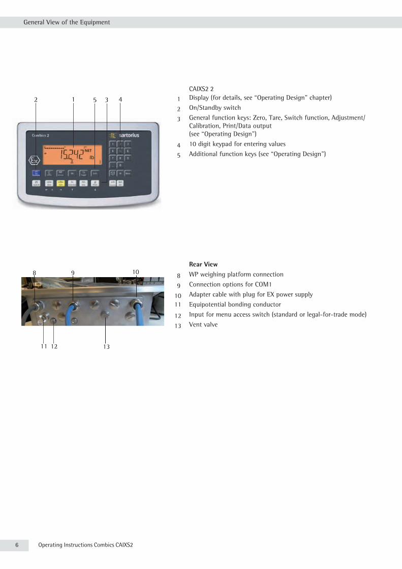
CAIXS2 2
1 Display (for details, see “Operating Design" chapter)
2 On/Standby switch
3 General function keys: Zero, Tare, Switch function, Adjustment/Calibration, Print/Data output (see “Operating Design")
4 10 digit keypad for entering values
5 Additional function keys (see “Operating Design")
Rear View
8 WP weighing platform connection
9 Connection options for COM1
10 Adapter cable with plug for EX power supply
11 Equipotential bonding conductor
12 Input for menu access switch (standard or legal-for-trade mode)
13 Vent valve
8 9 10
11 12 13
Order no. Price in €
CAIXS2 1.500
Preconfiguration with platform series CAPXS, IU, IF; verification by the manufacturer; calibration for the place of use;
mounting optional dataoutputs;
removable connection between terminal and platform can be ordered under VF2829. Please ask your sales representative.
• Networking of up to 8 indicators
• Suitable for: mounting on a bench, attaching to floor stand or columns,
mounting on a wall or installation in a switch cabinetCombics 2 Ex-Indikator
Description
Combics 2 Ex-Indicator
Stainless steel housing with cable glance.
Selectable is an A/D converter or digital interface to connect one scale in total.
Standard: 1 selectable data interface RS 232/485/422
Pre-assembled adapter cable for power supply modules.
The power supply for CAIXS2 is not included in the equipment supplied (see accessories).
Explosion protected scales for hazardous areas - Combics Ex-Indicator CAIXS2
• For use in Zones 1 (explosive gases) and Zone 21 (explosive dusts)
• ATEX: II 2G Ex ia IIC T4 Gb
II 2D Ex ia IIIC T80°C Db
• Allows the connection of one analogue Sartorius platforms Combics-Ex,
IFXS4, IUXS4, or one IS-X precision platforms, Signum Ex scale or load
cells with suitable specifications to be connected in Zone 1, 21, 20
• Verifiable class III, IIII
• Very easy to read display
12 3 45

Operating Instructions Combics CAIXS2 7
Installation
InstallationWhen a CAIXS2 indicator is ordered with special equipment, the desired options come pre-loaded from the factory.
Storage and Shipping Conditions
3
Excessive vibrations may compromise the safety of the equipment.
– Do not expose the equipment to unnecessarily extreme temperatures, moisture, shocks, blows or vibration.
– Permissible storage temperature: -20 to +60°C.
Installation LocationAvoid adverse influences at the place of installation: – extreme temperatures (operating temperature: -10°C to +40°C)– aggressive chemical vapors– extreme moisture (according to IP protection rating).
Unpacking the Equipmentt After unpacking the device, check it for any visible damage as a result of rough
handling during shipment.y If you detect any damage, proceed as directed under “Safety Inspection" in the
chapter entitled “Care and Maintenance."tSave the original packaging for any future transport.
Unplug all connected cables before packing the equipment.
Checking Package Contents– Indicator– Operating instructions– Options (special accessories) as listed on the bill of delivery
Acclimatizing the DeviceCondensation can form on the surfaces of a cold device when it is brought into a substantially warmer area. t Allow the device to acclimatize for about 2 hours at room temperature, leaving
it unplugged from the supply voltage.

8 Operating Instructions Combics CAIXS2
Getting Started
Getting Started
1.) Connect weighing platform to the indicator.2.) CAIXS2 Indicators have an intrinsically safe data interface which can be
connected to a computer (or any other peripheral device) using a barrier (e.g. YDI05-Z).
3.) Connect the AC adapter.4.) Configure the analog/digital converter (ADC).5.) Carry out an alignment: Adjustment.
Connecting Weighing PlatformsYou can connect any intrinsically safe, analog Sartorius platform to your CAIXS2 Indicator. Refer also to the Verification of Intrinsic Safety, the EC Type Examination Certificate for the CAIXS2 and the load cell or analog weighing platform to be connected.
3
The load cell should be connected by a certified technician who has received specialized training from Sartorius. Any installation work that does not conform to the instructions in this manual results in forfeiture of all claims under the manufacturer’s warranty.
3
Make sure the CAIXS2 is disconnected from the power before starting any connection work.
t Set up the weighing platform (see operating instructions for the weighing platform).
t Place the cable from the weighing platform next to the indicator. t Open the Combics indicator:
Loosen the ten cap nuts on the front panel. Remove the front panel.
Installing Connection and Interface Cables
3
The cable gland (IP69K protection) is pre-mounted on the indicator. Please use extreme caution when performing any work on the equipment that affects this cable gland. You must use a torque wrench. The torque for this cable gland is 5 Nm.
Preparing the Cable t Strip approx. 14 cm from the end of the cable.
t Shorten the shielding to approx. 2 cm and pull back over the insulation.t Strip approximately 5 mm of the insulation from the wires of the connecting
cable and affix ferrules to the wire ends.
Operating Instructions Combics CAIXS2 9
Getting Started
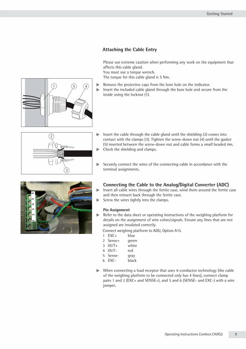
Attaching the Cable Entry Please use extreme caution when performing any work on the equipment that
affects this cable gland. You must use a torque wrench. The torque for this cable gland is 5 Nm.
41 5 t Remove the protective caps from the bore hole on the indicator.t Insert the included cable gland through the bore hole and secure from the
inside using the locknut (1).
2
3
t Insert the cable through the cable gland until the shielding (2) comes into contact with the clamps (3). Tighten the screw-down nut (4) until the gasket (5) inserted between the screw-down nut and cable forms a small beaded rim.
t Check the shielding and clamps.
t Securely connect the wires of the connecting cable in accordance with the terminal assignments.
Connecting the Cable to the Analog/Digital Converter (ADC) t Insert all cable wires through the ferrite case, wind them around the ferrite case
and then reinsert back through the ferrite case.t Screw the wires tightly into the clamps.
Pin Assignment t Refer to the data sheet or operating instructions of the weighing platform for
details on the assignment of wire colors/signals. Ensure any lines that are not assigned are insulated correctly.Connect weighing platform to ADU, Option A151 EXC+ blue2 Sense+ green3 OUT+ white4 OUT- red5 Sense- gray6 EXC- black
t When connecting a load receptor that uses 4-conductor technology (the cable of the weighing platform to be connected only has 4 lines), connect clamp pairs 1 and 2 (EXC+ and SENSE+), and 5 and 6 (SENSE- and EXC-) with a wire jumper.
1
2
3
4
5
6

10 Operating Instructions Combics CAIXS2
Getting Started
Instead of an analog/digital converter (ADC), you could also install a data interface to connect an intrinsically safe digital weighing platform or balance (e.g. an IS......-X).
Connection using RS232 (Option A16)1 CTS green2 DTR brown3 RxD yellow4 TxD white5 GND gray6 GND
Connection using RS485 (Option A19)1 RxD-TxD-P white2 RxD-TxD-N yellow3 GND gray4 GND
3 Do not insulate cable ends you are not using!
Connecting Intrinsically Safe Data CablesConnect intrinsically safe data cables to COM 1 (RS232, RS485 or RS422 and intrinsically safe control signals). For pin assignments on the data interface board, see 66015-741-50.
1 2
3
4
5
6
1 2
3
4
5 6
1 2
3
4
Der neue Combics Ex- Indikator - CAIXS2
CAIXS2 angeschlossen an...
IF-X IS-X IU-X Combics- X
Combics 2 Ex
Ex Wägezellen

Operating Instructions Combics CAIXS2 11
Getting Started
Pin Allocations on the CAIXS2 Data Outputs (COM1)
Option A21 A22 A23RS232 + RS422 RS485 + Pin*) Pin**)
Digital I/Os Digital I/Os CTS GND GND A 1RxD GND TxD-RxD_P J 2TxD TxD_N TxD_RxD_N K 3DTR TxD_P --- N 4GND DRT_P GND C 5GND RxD_N GND M 6GND DTR_N GND B 7UNI_IN --- UNI_IN O 8SET --- SET D 9PAR CTS_N PAR E 10MIN CTS_P MIN F 11MAJ RxD_P MAJ G 12
* 14-pin plug on adapter cable:
** 12-pin terminal block on the data adapter board:
Plug the 12-pin connection cable into the corresponding type of data output(see data sheet External Data Interface).
O
D
KA
M
N
J
G
B
C
EF
H
L
1 2 3 4 5 6 7 8 9 10 11 12

12 Operating Instructions Combics CAIXS2
Getting Started
t Re-attach the front panel and tighten the ten cap nuts with a torque of 1 Nm.
Connecting the Device to AC Power
Power is supplied via an external power supply device, which is provided with the equipment.
3
The power connection must be made in accordance with the regulations applicable in your country.
Make sure that the voltage rating printed on the manufacturer's ID label is identical to that of your local mains voltage. If the voltage specified on the label or the plug design of the AC adapter do not match the rating or standard you use, please contact your Sartorius office or dealer.
t Check the voltage rating and plug design.t The device must be plugged into a properly installed wall outlet.
Protection Class 1 Device t The device must be plugged into a properly installed wall outlet that has
a protective grounding conductor (PE).
Safety Precautions
3 If you use an electrical outlet that does not have a protective grounding conductor,
ensure that an equivalent protective conductor is installed by a certified electrician (as specified in the applicable regulations for installation in your country). The protective effect must not be negated by using an extension cord without a protective grounding conductor.
Before using for the first time, any superstructure parts must be completely installed. Avoid connecting the equipment to lines that have a heavy electrical load, e.g. compressors, large machinery, etc.
Warm-Up Time To deliver exact results, the device must warm up for at least 30 minutes after
connection to AC power. Only after this time will the device have reached the required operating temperature.

Operating Instructions Combics CAIXS2 13
Operating Design
Operating Design Display and Keypad
1 Display
2 On/Standby key
3 Keys with no function
4 Zero key
5 Tare key
6 Function key unit conversion
7 Start calibration or adjustment
8 Print key (data output)
9 Toggle unit between normal and 10-fold higher resolution
10 View gross value (net value plus tare) View net value (gross value minus tare)
11 Product data memory
12 ID key for entering the operator ID
13 Numeric keypad
14 Toggle between application program and application- specific information
15 Display of applications and manual tare values
16 Toggle key (function depends on application)
17 OK key (function depends on application)
18 Reference value key (function depends on application)
19 Clear function key (function depends on active application)
Order no. Price in €
CAIXS2 1.500
Preconfiguration with platform series CAPXS, IU, IF; verification by the manufacturer; calibration for the place of use;
mounting optional dataoutputs;
removable connection between terminal and platform can be ordered under VF2829. Please ask your sales representative.
• Networking of up to 8 indicators
• Suitable for: mounting on a bench, attaching to floor stand or columns,
mounting on a wall or installation in a switch cabinetCombics 2 Ex-Indikator
Description
Combics 2 Ex-Indicator
Stainless steel housing with cable glance.
Selectable is an A/D converter or digital interface to connect one scale in total.
Standard: 1 selectable data interface RS 232/485/422
Pre-assembled adapter cable for power supply modules.
The power supply for CAIXS2 is not included in the equipment supplied (see accessories).
Explosion protected scales for hazardous areas - Combics Ex-Indicator CAIXS2
• For use in Zones 1 (explosive gases) and Zone 21 (explosive dusts)
• ATEX: II 2G Ex ia IIC T4 Gb
II 2D Ex ia IIIC T80°C Db
• Allows the connection of one analogue Sartorius platforms Combics-Ex,
IFXS4, IUXS4, or one IS-X precision platforms, Signum Ex scale or load
cells with suitable specifications to be connected in Zone 1, 21, 20
• Verifiable class III, IIII
• Very easy to read display
17 1618 1519 14
1 13
2 12
11
3 10
4 9
5 86 7
14 Operating Instructions Combics CAIXS2
Operating Design
Key Functions
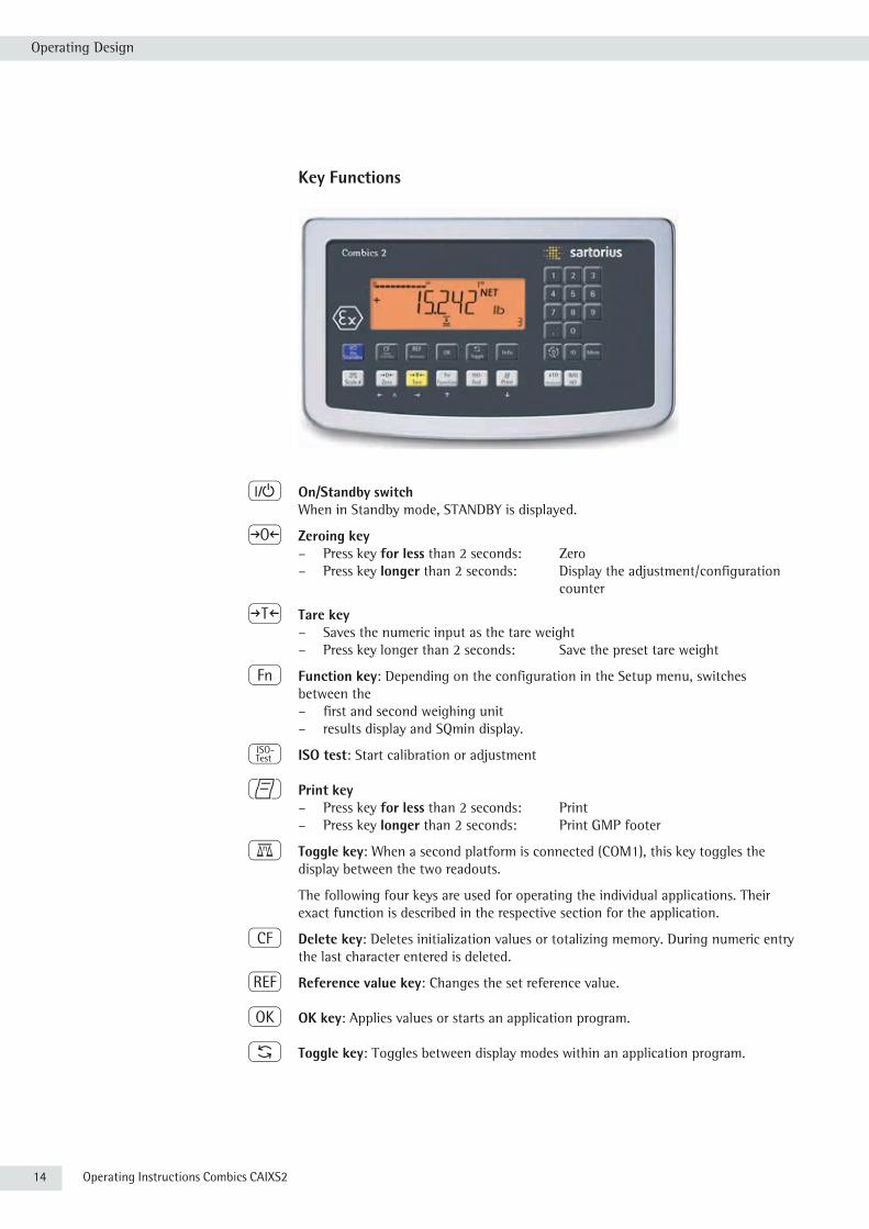
e On/Standby switchWhen in Standby mode, STANDBY is displayed.
( Zeroing key – Press key for less than 2 seconds: Zero
– Press key longer than 2 seconds: Display the adjustment/configuration counter
) Tare key– Saves the numeric input as the tare weight– Press key longer than 2 seconds: Save the preset tare weight
k Function key: Depending on the configuration in the Setup menu, switches between the – first and second weighing unit– results display and SQmin display.
J ISO test: Start calibration or adjustment
p Print key – Press key for less than 2 seconds: Print
– Press key longer than 2 seconds: Print GMP footer
n Toggle key: When a second platform is connected (COM1), this key toggles the display between the two readouts.
The following four keys are used for operating the individual applications. Their exact function is described in the respective section for the application.
c Delete key: Deletes initialization values or totalizing memory. During numeric entry the last character entered is deleted.
r Reference value key: Changes the set reference value.
O OK key: Applies values or starts an application program.
w Toggle key: Toggles between display modes within an application program.
Order no. Price in €
CAIXS2 1.500
Preconfiguration with platform series CAPXS, IU, IF; verification by the manufacturer; calibration for the place of use;
mounting optional dataoutputs;
removable connection between terminal and platform can be ordered under VF2829. Please ask your sales representative.
• Networking of up to 8 indicators
• Suitable for: mounting on a bench, attaching to floor stand or columns,
mounting on a wall or installation in a switch cabinetCombics 2 Ex-Indikator
Description
Combics 2 Ex-Indicator
Stainless steel housing with cable glance.
Selectable is an A/D converter or digital interface to connect one scale in total.
Standard: 1 selectable data interface RS 232/485/422
Pre-assembled adapter cable for power supply modules.
The power supply for CAIXS2 is not included in the equipment supplied (see accessories).
Explosion protected scales for hazardous areas - Combics Ex-Indicator CAIXS2
• For use in Zones 1 (explosive gases) and Zone 21 (explosive dusts)
• ATEX: II 2G Ex ia IIC T4 Gb
II 2D Ex ia IIIC T80°C Db
• Allows the connection of one analogue Sartorius platforms Combics-Ex,
IFXS4, IUXS4, or one IS-X precision platforms, Signum Ex scale or load
cells with suitable specifications to be connected in Zone 1, 21, 20
• Verifiable class III, IIII
• Very easy to read display

Operating Instructions Combics CAIXS2 15
Operating Design
I Info key: Used to display application parameters and manual tare values (Info after pressing a follow-up key, e.g. ))
1, 2, 3 ... ., 0 Number block: Used to enter numeric values t To apply the value, press the corresponding function key (e.g. key ) to save
the entry as a manual tare value.t To delete the last character entered, press the c key.
D Application toggle key: Toggles between available applications
d ID key: Used to enter operator IDs
R Save key: Used to save values to the product data memory or load to the application
K Resolution toggle key: Toggles unit between normal and 10-fold higher resolution
L Gross/Net value key: Toggles between the gross or net value
Saving Settings in Weighing ModeAll application parameters saved (e.g. reference values) remain in memory and are available when:– the device has been switched off and then on again– you return to the originally selected application from a second one (e.g. when
you switch from Averaging back to Counting. all parameters saved for Counting are available).
Applying the Tare Weightt Place the tare object on the weighing platform.t Press the T key.y The value is applied as the tare value.
Input Through the Digital Control Port
You can connect an external hard drive or foot switch to the control port (universal interface). You can assign one of the following functions to the control port in the SETUP / CTRL IO / INPUT / PARAMET / EXT.KEYB menu:– p key– p key (hold) – ) key– J key– k key– n key– O key– ( key– e key– c key– I key– D key– K key– L key
16 Operating Instructions Combics CAIXS2
Operating Design
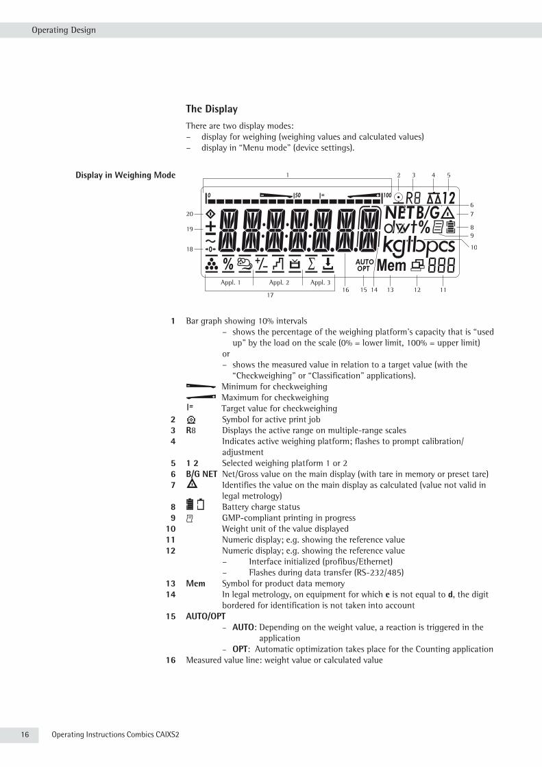
The DisplayThere are two display modes:– display for weighing (weighing values and calculated values)– display in “Menu mode" (device settings).
Display in Weighing Mode
1 Bar graph showing 10% intervals – shows the percentage of the weighing platform’s capacity that is “used
up" by the load on the scale (0% = lower limit, 100% = upper limit) or – shows the measured value in relation to a target value (with the
“Checkweighing" or “Classification" applications).Minimum for checkweighingMaximum for checkweighingTarget value for checkweighing
2 S Symbol for active print job 3 R8 Displays the active range on multiple-range scales 4 Indicates active weighing platform; flashes to prompt calibration/
adjustment 5 1 2 Selected weighing platform 1 or 2 6 B/G NET Net/Gross value on the main display (with tare in memory or preset tare) 7 k Identifies the value on the main display as calculated (value not valid in
legal metrology) 8 Battery charge status 9 p GMP-compliant printing in progress 10 Weight unit of the value displayed 11 Numeric display; e.g. showing the reference value 12 Numeric display; e.g. showing the reference value
– Interface initialized (profibus/Ethernet) – Flashes during data transfer (RS-232/485)
13 Mem Symbol for product data memory 14 In legal metrology, on equipment for which e is not equal to d, the digit
bordered for identification is not taken into account 15 AUTO/OPT
– AUTO: Depending on the weight value, a reaction is triggered in the application
– OPT: Automatic optimization takes place for the Counting application 16 Measured value line: weight value or calculated value
1 3 4 5
67
89
10
11121314151617
18
19
20
Appl. 1 Appl. 2 Appl. 3
2
Operating Instructions Combics CAIXS2 17
Operating Design
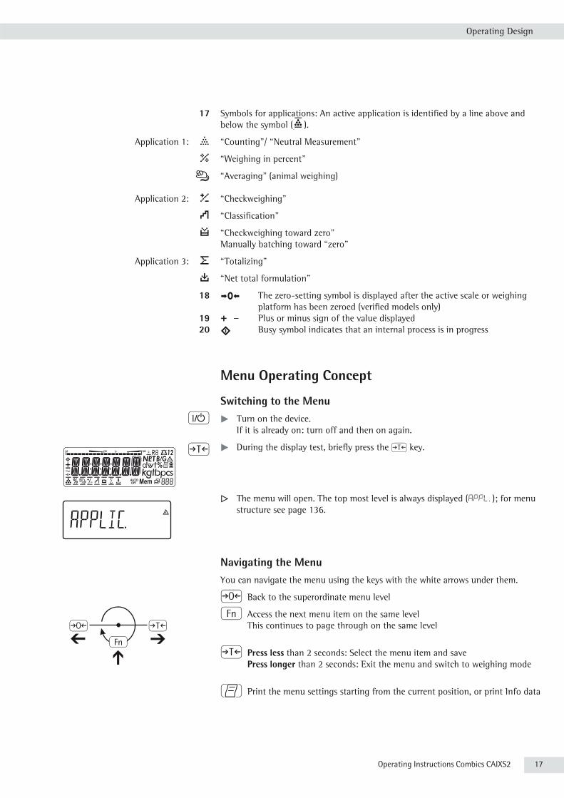
17 Symbols for applications: An active application is identified by a line above and below the symbol (
1 3 4 5
67
89
10
11121314151617
18
19
20
Appl. 1 Appl. 2 Appl. 3
2
).
Application 1: A “Counting"/ “Neutral Measurement"
B “Weighing in percent"
V “Averaging" (animal weighing)
Application 2: H “Checkweighing"
W “Classification"
Y “Checkweighing toward zero" Manually batching toward “zero"
Application 3: L “Totalizing"
M “Net total formulation"
18 U The zero-setting symbol is displayed after the active scale or weighing platform has been zeroed (verified models only)
19 + – Plus or minus sign of the value displayed 20 l Busy symbol indicates that an internal process is in progress
Menu Operating Concept
Switching to the Menu e t Turn on the device.
If it is already on: turn off and then on again.
) t During the display test, briefly press the ) key.
y The menu will open. The top most level is always displayed (APPL, ); for menu structure see page 136.
Navigating the MenuYou can navigate the menu using the keys with the white arrows under them.
( Back to the superordinate menu level
k Access the next menu item on the same level This continues to page through on the same level
) Press less than 2 seconds: Select the menu item and save Press longer than 2 seconds: Exit the menu and switch to weighing mode
p Print the menu settings starting from the current position, or print Info data

18 Operating Instructions Combics CAIXS2
Operating Design
Entering Numbers and Letters (without a Number Block)
( – Press the key for less than 2 seconds: Activate character to the left of the currently active character (when first character is active: exit the input mode without saving changes) – Press the key for longer than 2 seconds: Exit the input mode without
saving changes
(– Press the key for less than 2 seconds: Confirm currently active character and move 1 position to the right (after the last character: save input)
– Press key for longer than 2 seconds: Save current input and display the menu item
k– Cursor in first position, no characters entered yet: Delete character(s) and enter 0
– Change the displayed character; scroll forward (sequence: 0 ... 9, decimal point, minus sign, Z _ A, space)
p– Cursor in first position, no characters entered yet: Delete character(s) and enter a space
– Change the displayed character; scroll backward (sequence: space, A _ Z, minus sign, decimal point, 9 _ 0)
Enter number values (date and time, etc.) using the 10-key numeric keypad.
Menu DisplayBoth illustrations depict all of the main display elements and symbols that can be shown in Menu mode.
1 Selected menu item (e.g. printer for setting the connected printer)2 Menu history (note at highest menu level in the Setup menu)3 Note that other submenus are available
Display with the “codes" language setting 4 First level in the Setup menu
5 Second level in the Setup menu6 Third level in the Setup menu7 Currently active setting
Saving Menu SettingsThe parameters selected in the menu remain saved when you switch to weighing mode or turn off the device. You can block access to the Setup menu by requiring a password to prevent unauthorized or accidental setting changes.
1
32
23
4 5 6 7

Operating Instructions Combics CAIXS2 19
Operating Design
ConfigurationsBasic settings are made in the Menu mode by selecting the desired parameters. These are divided into the following groups (first menu level); for menu structure see page 136:– Application parameter APPLIC.
– Function key fn-key
– Device parameter SETUP – Device-specific information Info – User language LANGUAG.
When used in legal metrology, not all parameters can be accessed. Only those parameters that can be selected are displayed. Factory-set parameters are identified by an “*" in the list starting on page 137.
Printing Parameter Settingst Access the Menu mode (see page 35).t Press the p key.The scope of the printout depends on the position in the setup. It may take several seconds.
Language SettingsExample: Select the language “German." The factory setting for language is “English."Menu: appl / LANG .
e t Turn on the device.
t While all segments are lit, press the ( key briefly.
y The first item in the main menu is shown: APPL.
k k ... t Press the k key until the LANGuag. menu item is displayed for the language setting.
) t Press the ) key to access the language setting sub-menu.
y The currently set language is displayed.
k k ... t Press the k key until GERMAN is displayed.
) t Press the ) key to save the selection.
uag.

20 Operating Instructions Combics CAIXS2
Operating Design
y The small circle indicates that the setting has been saved.
( Use the ( key to exit the menu level to make additional settings if required.
or
) Press the ) key longer than 2 seconds to exit the menu.
Setting Up Password Protection e t Turn on the device.
t While all segments are lit, press the ( key briefly.
y The first item in the main menu is shown: APPLIC.
k k ... t Press the k key until the SETUP menu item is displayed.
) t Press the ) key to open the Setup sub-menu. y The first parameter in the Setup sub-menu is displayed: WP-1.
k k ... t Press the k key until BEN.-CODE is displayed.
) t Press the ) key to open the menu item.
y The position for the first character to be entered flashes.
p k t Use the p and k keys to select the desired character. p starts the character selection with A alphabetically and k starts the character selection with 0 and counts upward.
Alternatively, enter a number value using the 10-key numeric keypad directly.
°

Operating Instructions Combics CAIXS2 21
Operating Design
) t To apply a character, press the ) key.
t Enter all additional characters of the password as described above. t Press and hold the ) key to save the password.
( Use the ( key to exit the menu level to make additional settings if required.
or
) Press the ) key longer than 2 seconds to exit the menu.
Changing or Deleting Passwords t In the setup sub-menu, open the ben.code menu item as described above.y The old password must be entered to change or delete a password.t To change a password, overwrite the old password.t To delete a password, enter spaces and press the ) key.
22 Operating Instructions Combics CAIXS2
Configuring Weighing Platforms
Configuring Weighing Platforms
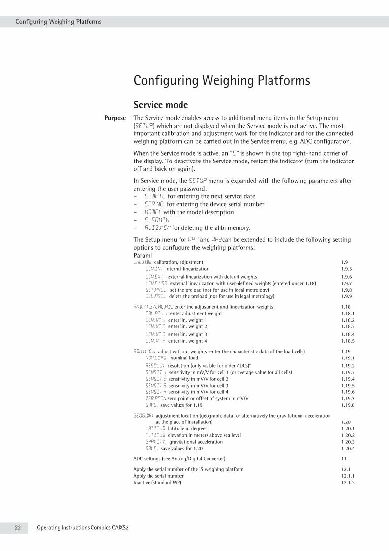
Service mode Purpose The Service mode enables access to additional menu items in the Setup menu
(setup) which are not displayed when the Service mode is not active. The most important calibration and adjustment work for the indicator and for the connected weighing platform can be carried out in the Service menu, e.g. ADC configuration.
When the Service mode is active, an “S" is shown in the top right-hand corner of the display. To deactivate the Service mode, restart the indicator (turn the indicator off and back on again).
In Service mode, the Setup menu is expanded with the following parameters after entering the user password: – S-DATE for entering the next service date– SER.No. for entering the device serial number– MODEL with the model description – S-SQMIN
– ALIB.MEM for deleting the alibi memory.
The Setup menu for WP1 and WP2can be extended to include the following setting options to confugure the weighing platforms:Param1cal.adj calibration, adjustment 1.9 lIN.INT internal linearization 1.9.5
lIN.ext. external linearization with default weights 1.9.6 lIN.e.usr external linearization with user-defined weights (entered under 1.18) 1.9.7 SET.PREL. set the preload (not for use in legal metrology) 1.9.8 DEL.PREL delete the preload (not for use in legal metrology) 1.9.9
HND.XT.G/CAL.ADJ enter the adjustment and linearization weights 1.18 CAL.ADJ.1 enter adjustment weight 1.18.1 LIN. WT.1 enter lin. weight 1 1.18.2 LIN. WT.2 enter lin. weight 2 1.18.3
LIN. WT.3 enter lin. weight 3 1.18.4 LIN. WT.4 enter lin. weight 4 1.18.5
ADJ.W/O.W adjust without weights (enter the characteristic data of the load cells) 1.19 NOM.LOAD. nominal load 1.19.1
RESOLUT resolution (only visible for older ADCs)* 1.19.2 SENSIT.1 sensitivity in mV/V for cell 1 (or average value for all cells) 1.19.3 SENSIT.2 sensitivity in mV/V for cell 2 1.19.4 SENSIT.3 sensitivity in mV/V for cell 3 1.19.5 SENSIT.4 sensitivity in mV/V for cell 4 1.19.6 ZER.POIN zero point or offset of system in mV/V 1.19.7 SAVE. save values for 1.19 1.19.8
GEOG.DAT adjustment location (geograph. data; or alternatively the gravitational acceleration at the place of installation) 1.20 LATITUD latitude in degrees 1 20.1 ALTITUD elevation in meters above sea level 1 20.2 GRAVITY. gravitational acceleration 1 20.3 SAVE. save values for 1.20 1 20.4
ADC settings (see Analog/Digital Converter) 11
Apply the serial number of the IS weighing platform 12.1Apply the serial number 12.1.1Inactive (standard WP) 12.1.2
Operating Instructions Combics CAIXS2 23
Configuring Weighing Platforms
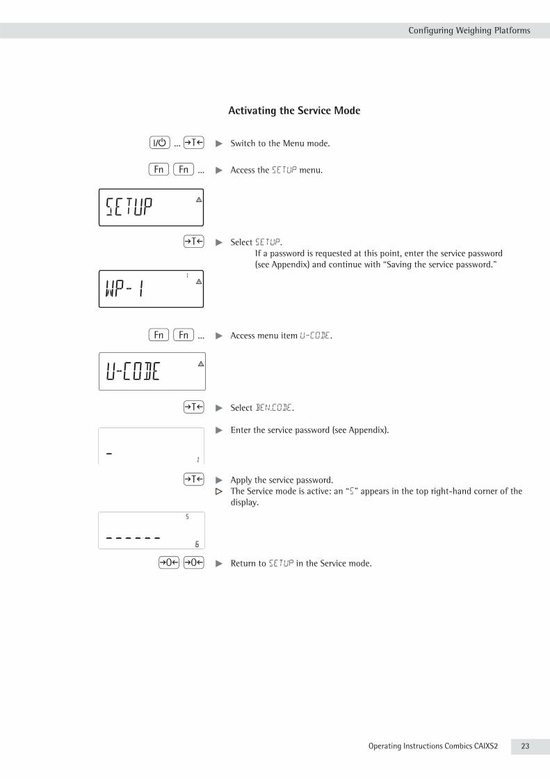
Activating the Service Mode
e ... ) t Switch to the Menu mode.
k k ... t Access the Setup menu.
) t Select Setup. If a password is requested at this point, enter the service password (see Appendix) and continue with “Saving the service password."
k k ... t Access menu item U-CODE.
) t Select ben.Code.
t Enter the service password (see Appendix).
) t Apply the service password.y The Service mode is active: an “S" appears in the top right-hand corner of the
display.
( ( t Return to Setup in the Service mode.

24 Operating Instructions Combics CAIXS2
Configuring Weighing Platforms
Analog/Digital Converter (ADC) Purpose Adjust the parameters of the analog/digital converter to the connected load cell or
weighing platform. After ADC configuration, the ADC in connection with the load sensor is defined as a scale.
3
Once the ADC configuration has been locked, the indicator can no longer be used to influence weighing results. The scope of functions available in the weighing instrument is defined by the A/D converter. Weighing functions that can be activated include reading weight values, taring, adjustment, reading the tare value and saving/deleting the tare entry.
Setup information – ADC configuration is only possible when the menu access switch is open. Close the menu access switch after ADC configuration, as otherwise there will not be any display of the conditions “overload" ( H ) and “underload" ( L ).
– Before ADC configuration, you must first set whether or not the weighing platform will be used as a standard or verifiable weighing platform under menu item 9.1.
– When the Service mode is activated, the ADC configuration takes place in the Setup menu under WP-1 for the first weighing platform and under COm1 /
WP-2 for the second weighing platform.
3
If you return to the highest level of the Setup menu without saving the configuration parameters beforehand (menu item 11.10) any settings that have been made will be deleted.
– The settings are made in the corresponding Setup menu under menu item 11.– Enter the maximum capacities in a suitable weight unit, without any decimal
places (decimal places will be truncated by the rounding function).– Entries made in the ADC configuration will not be affected by a menu reset
(returning the setup parameters to their factory settings).
Factory settings/Reset menu 9.1 wt.para
STANDRD Standard configuration 9.1.3
RANGE Ranges 11.3 SINGLE Single-range scale 11.3.1 MULT.INT Multi-interval scale 11.3.2 MULT.RNG Multiple-range scale 11.3.3
SINGLE Single-range scale 11.4 d Scale interval d 11.4.1 MAX Max. load 11.4.4
MULT.INT Multi-interval scale 11.5 d Scale interval d 11.5.1 RANGE 1 Range 1 11.5.4 RANGE 2 Range 2 11.5.5 RANGE 3 Range 3 11.5.6 max Max. load 11.5.7
MULT.RNG Multiple-range scale 11.6 d Scale interval d 11.6.1 RANGE 1 Range 1 11.6.4 RANGE 2 Range 2 11.6.5 RANGE 3 Range 3 11.6.6 MAX Max. load 11.6.7
WT.UNIT Available weight units 11.7 FREE User-defined /o 11.7.1 g Grams /g 11.7.2 kg Kilograms/kg 11.7.4 … t Tons/t 11.7.21 lb Pound:ounces/lb o 11.7.22

Operating Instructions Combics CAIXS2 25
Configuring Weighing Platforms
CAL.UNIT Calibration/Adjustment unit 11.8 FREE User-defined /o 11.8.1 g Grams /g 11.8.2 kg Kilograms/kg 11.8.3 ... t Tons/t 11.8.21
SAVE Save configuration parameters 11.10
YES Yes 11.10.1 NO No 11.10.2

26 Operating Instructions Combics CAIXS2
Configuring Weighing Platforms
Setting Parameters for ADC Configuration Standard or verifiable configuration In ADC configuration, you must first select whether the weighing platform should
be configured as a standard or verifiable (for use in legal metrology) weighing platform.– Standard configuration STANDRD (9.1.3) – Verifiable configuration VERIF. (9.1.4)
Configuration unit 1.WT.UNIT Menu item 1.7
The weight unit used in the ADC configuration must have previously been selected here.
Range selection RANGE Menu item 11.3Depending on the setting under this menu item, the Menu items 11.5, 11.6 and 11.7 will either be displayed or will not be displayed for further configurations. – Single-range scale (11.3.1)
The entire weighing capacity is divided into decimal numbers dependent on the smallest scale interval d and the maximum weight. The readability corresponds to the scale interval d.
– Multiple-range scale (11.3.2) A multiple-range scale has two or three weighing ranges. When the range limit for the lower weighing range is exceeded, the scale switches into the next highest weighing range (lower resolution). The scale only switches back to the lower weighing range (higher resolution) when the weighing platform has been completely unloaded after pressing the key (.
– Multi-interval scale (11.3.3) The function “Multi-interval scale" divides the weighing capacity into a maximum of three ranges with differing readability. The corresponding change takes place automatically at the defined range limits. Once the scale has been tared, the highest possible resolution is available even if the weighing platform is loaded.
Scale interval d Scale interval d indicates the resolution of the weighing instrument. The scale interval can only be entered in increments of 1, 2, 5, 10, 20, etc.When “Verifiable configuration” is used, this menu item is not displayed. When using verifiable or verified weighing platforms (classes l and m), scale interval d is the same as verification scale interval e.
Verification scale interval e Verification scale interval e indicates the resolution of the weighing instrument in legal metrology.
The scale interval can only be entered in increments of 1, 2, 5, 10, 20, etc.When “Standard configuration" is used, this menu item is not displayed.
Maximum load (max. load) The maximum load is the maximum amount of weight that may be placed on the weighing platform. When heavier weights are used the weighing instrument displays overload “H".The scale intervals of the weighing instrument are calculated using the maximum load and the scale interval d (e.g. max. capacity = 15.000 kg, smallest scale interval d = 0.005 kg yields 3000 scale intervals). In legal metrology the total number of intervals must be no more than 3000 e, and when using multi-interval scales there must not be more than 3000 e intervals per range.In standard operation, as opposed to legal metrology, you can define a “Super Range” weighing instrument of over 3000 intervals. These parameters, however, may be influenced by physical restrictions.
Operating Instructions Combics CAIXS2 27
Configuring Weighing Platforms
Minimum load (min. load) When “Standard configuration” is used, this menu item is not displayed. The minimum load of the connected weighing platform is entered under this menu item. The minimum load for scales of class l is 20 e and 10 e for class m. Attention: The function of the minimum load setting is to warn operators that below this limit, the summation of tolerances might lead to significant measure-ment errors. In Germany, for example, initial weights below the minimum load are not allowed.
Available weight units WT.UNIT Menu item 11.7
This menu item is used to select the weighing units that have been cleared for use in weighing. All units marked with a circle (o) have been cleared for use, multiple selection is possible.
Calibration/Adjustment unit Cal.Unit Menu item 11.8This menu item is used to select the weighing unit that must be used for a calibration/adjustment. The selected unit is then valid as a calibration/adjustment unit even when a different unit is used during normal weighing operation.
Save parameters SAVE Menu item 11.10The ADC configuration data is saved by selecting Menu item 11.10.1.
28 Operating Instructions Combics CAIXS2
Configuring Weighing Platforms
Configuring the A/D Converter (ADC)The weighing platform must already be connected.
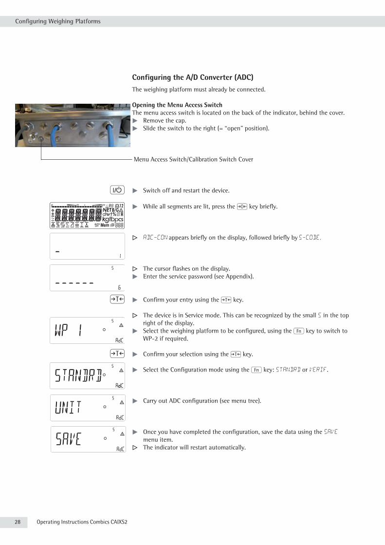
Opening the Menu Access SwitchThe menu access switch is located on the back of the indicator, behind the cover.
t Remove the cap.t Slide the switch to the right (= “open" position).
Menu Access Switch/Calibration Switch Cover
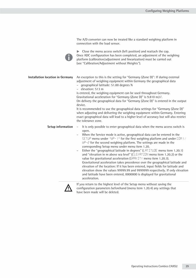
e t Switch off and restart the device.
t While all segments are lit, press the ( key briefly.
y ADC-CON appears briefly on the display, followed briefly by S-CODE.
y The cursor flashes on the display.t Enter the service password (see Appendix).
) t Confirm your entry using the ) key.
y The device is in Service mode. This can be recognized by the small S in the top right of the display.
t Select the weighing platform to be configured, using the k key to switch to WP-2 if required.
) t Confirm your selection using the ) key.
t Select the Configuration mode using the k key: STANDRD or VERIF.
t Carry out ADC configuration (see menu tree).
t Once you have completed the configuration, save the data using the SAVE menu item.
y The indicator will restart automatically.
Operating Instructions Combics CAIXS2 29
Configuring Weighing Platforms
The A/D converter can now be treated like a standard weighing platform in connection with the load sensor.
t Close the menu access switch (left position) and reattach the cap. h Once ADC configuration has been completed, an adjustment of the weighing
platform (calibration/adjustment and linearization) must be carried out (see “Calibration/Adjustment without Weights").
Installation location in Germany An exception to this is the setting for “Germany (Zone D)": If during external adjustment of weighing equipment within Germany the geographical data– geographical latitude: 51.00 degrees N– elevation: 513 mis entered, the weighing equipment can be used throughout Germany. Gravitational acceleration for “Germany (Zone D)" is 9.810 m/s2. On delivery the geographical data for “Germany (Zone D)” is entered in the output device.It is recommended to use the geographical data settings for “Germany (Zone D)" when adjusting and delivering the weighing equipment within Germany. Entering exact geographical data will lead to a higher level of accuracy but will also restrict the tolerance zone.
Setup information – It is only possible to enter geographical data when the menu access switch is open.
– When the Service mode is active, geographical data can be entered in the Setup menu under “WP-1" for the first weighing platform and under COm1 /
WP-2 for the second weighing platform. The settings are made in the corresponding Setup menu under menu item 1.20.
– Either the “geographical latitude in degrees" (latitude menu item 1.20.1) and “elevation in m above sea level" (elevation menu item 1.20.2) or the value for gravitational acceleration (GRAVITY menu item 1.20.3).
Gravitational acceleration takes precedence over the geographical latitude and elevation of the location: If it has been entered, input fields for latitude and elevation show the values 99999.99 and 9999999 respectively. If only elevation and latitude have been entered, 0000000 is displayed for gravitational acceleration.
3
If you return to the highest level of the Setup menu without saving the configuration parameters beforehand (menu item 1.20.4) any settings that have been made will be deleted.
30 Operating Instructions Combics CAIXS2
Configuring Weighing Platforms
Procedure t Open menu access switch. If the device is part of a verified weighing facility, this will only be possible if the verification seal is broken. The weighing equipment must then be verified again.
t Activate the Service mode.t Select the weighing platform.t Enter the geographical data for the place of adjustment under menu items
1.20.1 to 1.20.3 and save them under menu item 1.20.4. The data can be obtained from the relevant land registry or Ordnance Survey.
t Carry out external calibration.t After the calibration, enter the geographical data for the place of installation
under menu items 1.20.1 to 1.20.3 and save them under menu item 1.20.4. t Close the menu access switch.y The weighing equipment can now be operated at the place of installation, and
within the abovementioned tolerance zone.
Note: The set geographical values are displayed during the adjustment procedure if the display of the data has been activated in the Setup menu under UTILIT menu item 8.12.2 (factory setting: 8.12.1, display deactivated).
When the display is activated the adjustment procedure is as follows:y If the elevation and geographical latitude are used, after the start of the CAL
adjustment procedure the word ALTITUD will appear briefly followed by the set elevation (in meters above sea level).
t Confirm the display using the ) key (cancel using the () key. y Then the word “LATITUD" will be displayed briefly followed by the set
geographical latitude in degrees. t Confirm the display using the ) key (cancel using the () key. y You are then asked to place the calibration weight on the weighing platform.
If gravitational acceleration has been entered instead of elevation and geographical latitude, the word GRAVITY t will appear briefly, followed by the value set for gravitational acceleration.
t Confirm the display using the ) key (cancel using the () key.
Menu structure for entering the geographical dataGEOG.DAT adjustment location (geograph. data; or alternatively the gravitational acceleration at the place of installation) 1.20 LATITUD latitude in degrees 1.20.1 ALTITUD elevation in meters above sea level 1.20.2 GRAVITY. gravitational acceleration 1.20.3 SAVE. save values for 1. 20 1.20.4

Operating Instructions Combics CAIXS2 31
Configuring Weighing Platforms
Entering Adjustment and Linearization Weights Purpose Entering adjustment and linearization weights.
Setup information – The Service mode must be activated in order for linearization weights to be entered under menu items 1.18.2 to 1.18.5 (see page 17).
– Adjustment and linearization weights are entered in the Setup menu under WP-1 for the first weighing platform and under COm1 / WP-2 for the second weighing platform. The settings are made in the corresponding Setup menu under menu item 1.18.
– The Service mode does not have to be activated in order for external user-defined adjustment weights to be entered under menu item 1.18.1.
– The adjustment and linearization weights must be entered in the unit selected for the ADC configuration under menu item 11.8.
Procedure t Activate the Service mode (only necessary if linearization weights are going to be entered).
t Select the weighing platform.t Enter the external user-defined adjustment weight under menu item 1.18.1.t Enter the external linearization weight under menu items 1.18.2 to 1.18.5.
Menu structure for entering the adjustment and linearization weights
MAN.EXT.W enter the adjustment and linearization weights 1.18 lCAL.ADJ enter external user-defined adjustment weight (Service mode not required) 1.18.1 LIN. WT.1 enter lin. weight 1 1.18.2 LIN. WT.2 enter lin. weight 2 1.18.3 LIN. WT.3 enter lin. weight 3 1.18.4 LIN. WT.4 enter lin. weight 4 1.18.5
Function Allocation of the J Key Purpose The J key is normally used for the calibration/adjustment function. For detailed
information about calibration and adjustment, see “Operation" starting on page 47. The following additional functions can be allocated to the key when the Service mode is activated:– external linearization with default weights (menu item 1.9.6)– external linearization with the linearization weights (menu item 1.9.7) entered
under menu item 1.18– internal linearization (menu item 1.9.5)– set preload (menu item 1.9.8) (only possible if not required for use in legal
metrology)– delete preload (menu item 1.9.9) (only possible if not required for use in legal
metrology).
3 Once linearization has been completed, or after a preload has been set or deleted,
the function of the J key must be reallocated back to its original function in the Setup menu, e.g. external calibration/adjustment with default weights (setup, menu item 1.9).
Menu structure for the function allocation of the J key
CAL.ADJ calibration, adjustment 1.9 CAL.EXT. calibration/adjustment with default weights (Service mode not required) 1.9.1 CAL.E-USR. calibration/adjustment with user-defined weights (entered under 1-18, Service mode not required) 1.9.3 LIN.INT internal linearization 1.9.5 LIN.EXT. external linearization with default weights 1.9.6 LINE.USR external linearization with user-defined weights (entered under 1.18) 1.9.7 SET.PREL. set the preload (only possible when used in non-legal metrology) 1.9.8 DEL.PREL. delete the preload (only possible when used in non-legal metrology) 1.9.9 blocked key blocked 1.9.10

32 Operating Instructions Combics CAIXS2
Configuring Weighing Platforms
External Linearization Setup information – External linearization when weighing in legal metrology is only possible when
the menu access switch is open.– The “external linearization" function must be allocated to the J key
(menu item 1.9.6 or 1.9.7).
3
Once linearization has been completed, the J key must be reallocated back to its original function in the Setup menu, e.g. external calibration/adjustment with default weights (Setup menu item 1.9).
Proceduret For scales used in legal metrology: Open the menu access switch.
( t Zero the weighing platform.
t Activate the Service mode.
J t Start linearization.
t After approximately 2 seconds you will be prompted to place the first linearization weight on the platform.
t Place the required weight on the platform.
y After a short time the difference between the measured value and the true weight of the sample will be displayed.
) t Save the linearization weight (cancel using the () key.
y You will then be prompted to place the second linearization weight on the platform.
t Repeat the procedure for all required linearization weights.
y After the last linearization weight has been saved you will be prompted to remove any load from the weighing pan.
t Unload the weighing pan.
t After a short period of time the zero point will be applied automatically and the indicator will automatically switch back to weighing mode.
t Re-close the menu access switch.

Operating Instructions Combics CAIXS2 33
Configuring Weighing Platforms
Set preload Setup information – Setting the preload when weighing in legal metrology is only possible using the
“Zero at Power On" menu item.– The “Set Preload" function (menu item 1.9.8) must be allocated to the J key.
3
Once the preload has been set, the J key must be reallocated back to its original function in the Setup menu, e.g. external calibration/adjustment with default weights (Setup menu item 1.9).
Procedure
( t Zero the weighing platform.
t Place the preload weight on the weighing platform.
J t Start the “Set Preload" function.
y After a short period of time the preload will be applied and the indicator will automatically switch back to weighing mode.

34 Operating Instructions Combics CAIXS2
Configuring Weighing Platforms
Clearing the Preload Setup information – Clearing the preload when weighing in legal metrology is only possible using
the “Zero at Power On" menu item.– The “Clear Preload" function (menu item 1.9.9) must be allocated to the
J key.
3
Once the preload has been deleted, the J key must be reallocated back to its original function in the Setup menu, e.g. external calibration/adjustment with default weights (Setup menu item 1.9).
Procedure
t Remove the preload weight from the weighing platform.
J t Start the “Clear Preload".
y After a short period of time the preload will be deleted and the indicator will automatically switch back to weighing mode.

Operating Instructions Combics CAIXS2 35
Configuring Weighing Platforms
Adjustment without WeightsIn the Service menu, adjustment without weights can be carried out by entering the characteristic data of the load cells.
3 Adjustment without weights may not be carried out on weighing equipment used in legal metrology.
Setup information – Adjustment without weights is only possible when the menu access switch is open in the Service menu.
– When the Service mode is active, the parameters necessary for adjustment without weights can be entered in the Setup menu under “WP-1" for the first weighing platform and under COm1 / WP-2 for the second weighing platform. The settings are made in the corresponding Setup menu under menu item 1.19.
– The “Nominal load" parameter must be entered in the “kg" unit.– The “Resolution" parameter must be entered in the “kg" unit and must
correspond to the scale interval “d" entered for the ADC configuration. This parameter is only available or visible with older ADCs.– The “Sensitivity" parameter is entered in mV/V (see the data sheet for the
value). - The “Zero Point" (Offset) parameter is entered in mV/V. This parameter is not visible with older ADCs.
h The data entered is saved by selecting menu item 1.19.7. After saving, the data will
no longer be able to be read.
Proceduret Open the menu access switch.t Activate the Service mode.t Select the weighing platform.t Enter the nominal load of the load cell(s) in kg under menu item 1.19.1. If the
weighing platform has multiple load cells, the nominal load must be multiplied accordingly (e.g. 4 load cells, each of which has a capacity of 50 kg, will produce a nominal load of 200 kg).
t Enter the resolution in kg under menu item 1.19.2. The value must correspond to the scale interval d entered under menu item 11.4.1.
This applies only to older ADCs.t Enter the sensitivity of the load cells in mV/V under menu item 1.19.3.
For weighing platforms with multiple load cells: Enter the individual values of the load cells in 1.19.3 to 1.19.6 or enter the average of all load cells in 1.19.3. Values for the zero point or the dead load are set under 1.19.7. This does not apply to older ADCs.
t Save the values for adjustment without weighing under menu item 1.19.8.t Close the menu access switch.
Menu Structure for Adjustment without WeightsADJ.W/O.W adjust without weights (enter the characteristic data of the load cells) 1.19 NOM.LOAD nominal load 1.19.1 RESOLUT resolution (only visible for older ADCs)* 1.19.2 SENSIT.1 sensitivity in mV/V for cell 1 (or average value for all cells) 1.19.3 SENSIT.2 sensitivity in mV/V for cell 2 1.19.4 SENSIT.3 sensitivity in mV/V for cell 3 1.19.5 SENSIT.4 sensitivity in mV/V for cell 4 1.19.6 ZER.POIN zero point or dead load in mV/V. (not for older ADCs)* 1.19.7 SAVE. save values for 1.19 1.19.8

36 Operating Instructions Combics CAIXS2
Operation
Operation
Weighing
This application is always available during operation.
Features: – Zeroing by pressing (– Storing the weight on the platform as a tare by pressing )– Taring container weight automatically– Using a 10-key keypad to enter tare weight– Deleting tare values by entering 0 and ) / c and ) – Toggling the display using the Fn key between: – 1st and 2nd weight unit – SQmin– Configuring the k key function in the “Fn key" Setup menu– 10-fold increased resolution using the K key– Toggling between the gross or net value using L Weighing with two
weighing platforms– Individual numeric ID codes for weight values– Printing weight value: – GMP printout – Automatic printout – Automatic data output (see Data Interfaces chapter)
Automatic Taring (APPLIC menu item 3.7):When the menu item is active (3.7.2), the first weight on the scale that exceeds the preset minimum load is stored in the tare memory at stability.The scale returns to the initial state when the load on the scale is less than 50% of the minimum load.
Minimum load for automatic taring and automatic printing (menu item 3.5):You can set the following for the minimum load:1 digit (no minimum load)2 digits5 digits10 digits20 digits50 digits100 digits200 digits500 digits1000 digits
The “digits" here refer to the scale intervals for the connected weighing platform. If the interval is 1 g and 1000 digits are required, the minimum load is 1000 g (1000 intervals).
If the weighing platform interval is 5 g and the same number of digits as above is required, the minimum load is 5000 g.
When the load exceeds the minimum load limit, the weighing platform is tared automatically and/or a report printout is generated automatically; however, this requires the corresponding menu items to be active for automatic taring (menu item 3.7.2) and for automatic printing (menu 7.15.2).

Operating Instructions Combics CAIXS2 37
Operation
Automatic printing (PROTOC menu item 7.15):When the menu item (7.15.2) is active, the first weight value that exceeds the minimum load is printed.If the menu item is also activated for automatic taring, it is only tared when the minimum load is exceeded. In this case, an automatic printout would only be generated when the second weight value exceeds the minimum load.
Main scale: first platform displayed on start-upYou can select the weighing platform to be displayed first when CAIXS2 is turned on in the Setup menu under “UTILIT" (menu item 8.11.).
38 Operating Instructions Combics CAIXS2
Operation
Adjustment/Configuration Counter for Standard cales Purpose Automatically record changes to adjustment and weighing parameters using two
independent counters. The values remain saved for the life of the device.
t To display both counters, press and hold the ( key for longer than 2 seconds.
y The “Configuration counter" is first of all shown in the weight display for 3 seconds (identified by a P). The “Adjustment counter" is then displayed for another 3 seconds (identified by a C). After 6 seconds, the information display turns off automatically.
Adjustment counter features: – Counter limited to 9999– Counter at “C 0000" for hardware commissioning– Counter cannot be reset– Counter is updated automatically when: – linearization, calibration/adjustment is successful – user calibration, adjustment or linearization weight is changed (menu 1.18.) – when the following parameters are changed: function of the q key (menu item 1.9.) zero setting range (menu item 1.11) tare/zero at power on (menu item 1.12) the above parameters are reset to factory settings (menu item 9.1.1).
Configuration counter features: – Counter limited to 9999– Counter at “P 0000" for hardware commissioning– Counter cannot be reset– Counter is updated automatically when: – the following parameters are changed: installation location (menu item 1.1.) application filter (menu item 1.2.) stability range (menu item 1.3.) taring (menu item 1.5) auto zero (menu item 1.6.) weight unit 1 (menu item 1.7.) weight unit 2 (menu item 3.1.) weight unit 3 (menu item 3.3.) the above parameters are reset to factory settings (menu item 9.1.1) – switching the k key to or from a 10-fold higher resolution – turning the application automatic taring on/off
(menu item 3.7.) – the application parameters are reset to factory settings (menu item 9.1.1).

Operating Instructions Combics CAIXS2 39
Operation
Device ParametersPassword ProtectionAccess to the Setup device parameters and the APPLIC application parameters can be password-protected against unauthorized changes in the Setup menu under U-CODE (see page 38).
KeypadThe keypad can be blocked and released for entry (menu item 8.3) in the SETUP menu under UTILIT / PARAMETER / KEYS.
Automatic Shutoff of CombicsIn the SETUP menu, the indicator can be set to shut off automatically using a timer under UTILIT / PARAMETER / AUTO.OFF (Menu item 8.7.).
Display LightingThe following settings can be made for display lighting in the SETUP menu under UTILIT / PARAMETER / BACKLIT:– on (8.8.1)– off (8.8.2)– off automatically using a timer (8.8.3).
TimerThe timer for switching off the device and/or display lighting can be set to 2, 4 or 10 minutes (menu item 8.9) in the SETUP menu under UTILIT / PARAMETER / TIMER.
Example: Switch on the device, zero the scale, tare the container weight, place sample in the container, toggle display to gross weight or to second weight unit or 10-fold resolution.
e t Turn on the device.
t All display segments appear (display test).
y The display for no load on the scale appears.
( t Press the ( key to zero the scale.
y The display for a zeroed scale appears.

40 Operating Instructions Combics CAIXS2
Operation
t Place the container on the weighing platform.
y The container weight is displayed.
) t Press the ) key to tare the scale.
y The display for a tared scale with a container appears.
t Place a sample in the container (in this example, 120.2 g).
y The display for a tared scale with weighing results appears.
L y Press the L key; the following is displayed: y the gross weight (in this example, 170.2 g = 50 g for container + 120.2 g for
sample)
k or press the k key; the following is displayed:
y weight value in the second weight unit (in this example, kg)
K or press the K key; the following is displayed:
y weight value display with 10-fold resolution. This display switches back automatically after 10 seconds.

Operating Instructions Combics CAIXS2 41
Operation
p t Press the p key to print a report.
EISENSCHMIDT
GOETTINGEN
8/12/2013 3:10 PM
--------------------
G# + 170.2 g
T + 50.0 g
N + 120.2 g
--------------------
Example Weighing: Enter value for tare using the numeric keys; print results.
e t Turn on the device.
t All display segments appear (display test).
y The display for no load on the scale appears. When Combics 2 is turned on, it is ready for weighing and zeros itself automatically. With no load on the scale, you can zero the weighing platform at any time by pressing ( .
250 t Enter the tare weight using the keypad (e.g. 250 g).
) t Press the ) key to apply the tare value.
t Place the container and material to be weighed on the scale.
y The net weight value is displayed.
L t Press the L key to display the gross weight.
42 Operating Instructions Combics CAIXS2
Operation
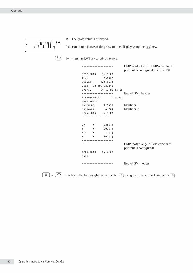
y The gross value is displayed.
You can toggle between the gross and net display using the L key.
p t Press the p key to print a report.
-------------------- GMP header (only if GMP-compliant printout is configured, menu 7.13)
8/12/2013 3:15 PM
Type CAIXS2
Ser.no. 12345678
Vers. C2 100.280810
BVers. 01-62-03 to 30
-------------------- End of GMP header EISENSCHMIDT Header GOETTINGEN
BATCH NO. 123456 Identifier 1 CUSTOMER 6.789 Identifier 2 8/24/2013 3:15 PM
--------------------
G# + 2250 g
T + 0000 g
PT2 + 250 g
N + 2000 g
--------------------
-------------------- GMP footer (only if GMP-compliant printout is configured)
8/24/2013 3:16 PM
Name:
-------------------- End of GMP footer
0 + ) To delete the tare weight entered, enter 0 using the number block and press ).

Operating Instructions Combics CAIXS2 43
Operation
Calibration and Adjustment Purpose Calibration determines the difference between the value displayed and the actual
weight on the platform. Calibration does not entail making any changes within the weighing equipment.
During adjustment, the difference between the measured value displayed and the true weight of a sample is corrected, or is reduced to an allowable level within maximum permissible error limits.
3 The temperature range (°C) listed on the ID label should not be exceeded during operation.
For servicing: External calibration/adjustment for verified scales of accuracy class l– External calibration/adjustment is blocked in legal metrology (switch cover is
sealed).– External calibration/adjustment is only possible after the seal is removed. If the
seal is broken, the validity of verification will become void and you must have your scale re-verified.
Using a verified scale in legal metrology with internal adjustment equipment:t Before use in legal metrology, the “internal adjustment" function should be
carried out at the installation location.
Opening the Menu Access SwitchThe menu access switch is located on the back of the indicator right next to the weighing platform connection (left-hand side).
t Remove the cap.t Slide the switch to the right (= “open" position, not subject to legal verification).
Characteristics Which of the following features are available depends on the weighing platform
connected. These features can be configured in the Setup menu:– external calibration/adjustment blocked in verified weighing instruments– external calibration/adjustment with the standard weight or weight set by a user
(not available on verified instruments): setup / wp-1 menu Menu item 1.9 “Calibration and Adjustment"
– specify the weight for external calibration/adjustment: setup / wp-1 menu Menu item 1.18 “enter adjustment weight"
– internal adjustment for IS weighing platforms (configure under: SETUP / WP-1 or COM1)
– block the J key to prevent use of the functions described above: setup / wp-1 menu Menu item 1.9 “Calibration and Adjustment"
– calibrate first; then adjust automatically or manually (not for verified weighing instruments): setup / wp-1 menu Menu item 1.10 “Calibration/Adjustment sequence"
– flashing n symbol as adjustment prompt. If more than one weighing platform is connected, the platform number is also displayed: setup / wp-1 menu Menu item 1.15. “Adjustment prompt"
– block external or enable calibration/adjustment: setup / wp-1 menu Menu item 1.16. “External calibration."
44 Operating Instructions Combics CAIXS2
Operation
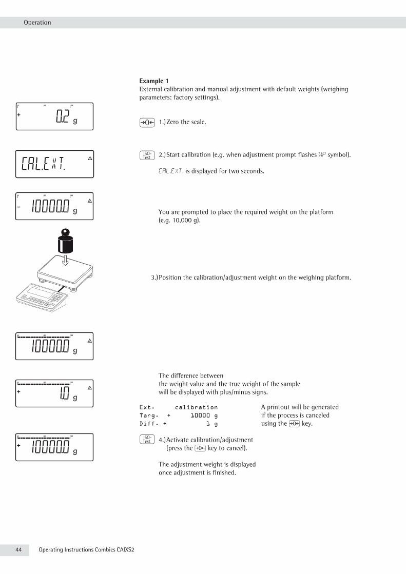
Example 1External calibration and manual adjustment with default weights (weighing parameters: factory settings).
( 1.) Zero the scale.
J 2.) Start calibration (e.g. when adjustment prompt flashes WP symbol).
cal.Ext. is displayed for two seconds.
You are prompted to place the required weight on the platform (e.g. 10,000 g).
3.) Position the calibration/adjustment weight on the weighing platform.
The difference between the weight value and the true weight of the sample will be displayed with plus/minus signs.
Ext. calibration A printout will be generatedTarg. + 10000 g if the process is canceledDiff. + 1 g using the ( key.
J 4.) Activate calibration/adjustment (press the ( key to cancel).
The adjustment weight is displayed once adjustment is finished.

Operating Instructions Combics CAIXS2 45
Operation
-------------------- A GMP-compliant printout is generated.02/24/2013 10:15 Type CAIXS2Ser.no. 12345678
Vers. C2 100.280810
BVers. 01-26-03 Software versions 01-26-03 to 01-26-30 can be printed.-------------------- Ext. Calibrate Targ. + 10000 g Diff. + 1 gExt. Adjustment Diff. + 0 g--------------------02/24/2013 10:15Name:
--------------------
Example 2External calibration and manual adjustment with freely selectable adjustment
weight (in the range 1/3 maximum load to maximum load).
( 1.) Zero the scale.
J 2.) Start calibration (e.g. when adjustment prompt flashes WP symbol).
cal.Ext. is displayed for two seconds.
You are prompted to place the required weight on the platform (e.g. 10,000 g).
5 + )
3.) Using the number block, enter the desired CAL weight
steps and confirm with ) (in this example, 5000.0 g).If the weight is too great or too small, an error message is displayed.

46 Operating Instructions Combics CAIXS2
Operation
4.) Position the calibration/adjustment weight on the weighing platform.
The adjustment weight is displayed once adjustment is finished.
Remove the adjustment weight from the weighing platform.
SQmin Function Purpose To display the allowable minimum sample quantity “SQmin" (sample quantity
minimum) in accordance with the United States Pharmacopoeia (USP). According to USP guidelines, the uncertainty of measurement may not exceed 0.1% of the sample quantity when substances are weighed with the highest degree of accuracy for volume determination. This additional function ensures that weighing results lie within defined tolerance limits corresponding to the requirements of your quality assurance system.
Prerequisites The scale must be set up by a service technician to be able to use the SQmin function. The technician will determine the permitted minimum sample quantity and load this to your scale using the guidelines of your QA system. He or she will document this setting via a “Weighing module test as per USP" certificate in which the measurements and min. sample quantity are logged. The SQmin function ensures that the weighing results correspond to USP guidelines. These SQmin settings cannot be changed by the user.
Features – Displaying the minimum sample quality: After you press the k key, the value is displayed in the text line for 4 seconds.
– If the minimum sample quantity has not been reached: The k symbol is displayed and weight values are marked with a “!" in the printout.
– GLP header: The minimum sample quantity entered for SQmin can be included on the printout.
Setting SQmin ParametersThe SQmin display must be turned on to use the SQmin function.
Menu: SETUP / SQMIN /
SQmin display: DISPLAY yes/no*Print in GLP header: GMP-DRK yes/no*
* = Factory setting
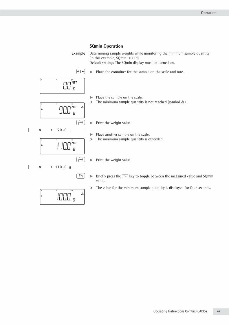
Operating Instructions Combics CAIXS2 47
Operation
SQmin Operation Example Determining sample weights while monitoring the minimum sample quantity
(in this example, SQmin: 100 g).Default setting: The SQmin display must be turned on.
) t Place the container for the sample on the scale and tare.
t Place the sample on the scale. y The minimum sample quantity is not reached (symbol k).
p t Print the weight value.
| N + 90.0 ! | t Place another sample on the scale.
y The minimum sample quantity is exceeded.
p t Print the weight value.
| N + 110.0 g |
k t Briefly press the k key to toggle between the measured value and SQmin value.
y The value for the minimum sample quantity is displayed for four seconds.
48 Operating Instructions Combics CAIXS2
Operation
Individual ID Codes (Identifiers)
You can assign codes (such as product name, batch number, etc.) for identification of measured values on printouts.
Features – You can assign up to six ID codes.– One name and one value can be assigned to each ID code.– Displaying individual IDs: press the d key.– The name is left-justified and the value is right-justified on the printout.
If the entire code is too long for one line, additional lines are printed.– Enter ID code names in the Setup menu under
SETUP / PRTPROT , menu item 7.4. The name can have a max. of 20 characters.
– Enter up to 40 characters for the value of the ID code. Press the d key to activate the input mode.
– Individual characters of the ID can be deleted using the c key.– If both the name and value fields are empty, no ID code is printed.– In the Setup menu, you can configure when and whether ID codes are printed
(see “Configuring Printouts" page 96).
Settings for Individual ID CodesMenu: SETUP/PRINT/PROTOC./ /header
Factory settings for ID code names: ID1: ID1
ID2: ID2
ID3: ID3
ID4: ID4
ID5: ID5
ID6: ID6
There are no factory settings for ID code values.

Operating Instructions Combics CAIXS2 49
Operation
Using Individual ID Codes Example Enter ID code names. “Batch number" and “Customer" should be entered for ID 1
and ID 2.
e ... ) t Open the menu.
k k ... ) t Select and open SETUP.
k k ... ) t Select and open PRINT.
) t Open PROTOC..
) t Open HEADLIN.
k k ... ) t Select and open INDENT. 1.
k p ... t Enter the name for the first identification (use the k and p keys or the number block), e. g. “Batch number".
) t To save the entry, press the ) ) key.
k ... ) t Select and open INDENT. 2.
k p ... t Enter a name for the 2nd ID, e.g. “customer".
) t To save, press the ) key.
( ( ... t To exit the sub-menu, press the ( key several times.

50 Operating Instructions Combics CAIXS2
Operation
Application Programs
Overview of Applications and Functions
UsageBasic weighing XSend print job/data record to peripheral device XLabel printer XSecond scale connection option optional (WP-2 using COM1)Counting XNeutral measurement XAveraging (animal weighing) XWeighing in percent XVerification XClassification XTotalizing XBatching/counting to target value XProduct data memory X
FunctionZero XTare XDate/time XExternal battery (rechargeable) optionalID codes (6 codes, 40 characters each) XAutomatic printout XAutomatic taring XManual taring XUnit conversion XIncreased resolution XGMP printout X
h Combination of applications
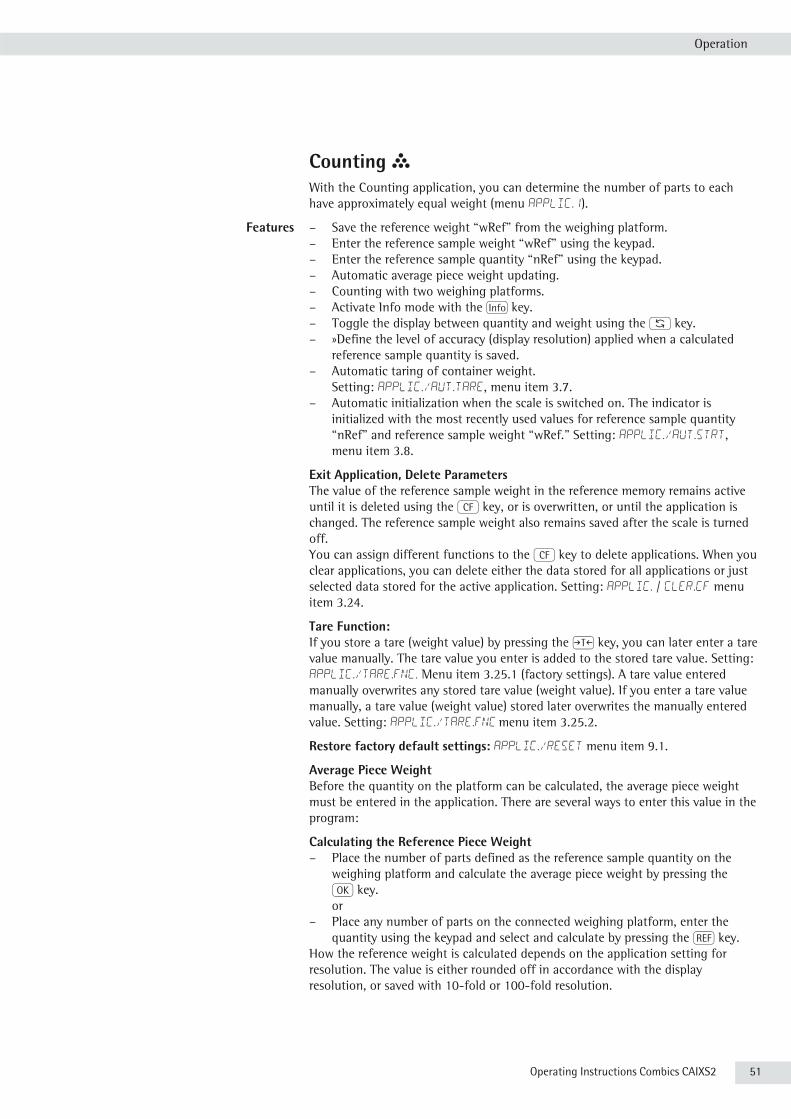
Operating Instructions Combics CAIXS2 51
Operation
Counting Z With the Counting application, you can determine the number of parts to each have approximately equal weight (menu APPLIC.1).
Features – Save the reference weight “wRef" from the weighing platform.– Enter the reference sample weight “wRef" using the keypad.– Enter the reference sample quantity “nRef" using the keypad.– Automatic average piece weight updating.– Counting with two weighing platforms.– Activate Info mode with the I key.– Toggle the display between quantity and weight using the W key.– »Define the level of accuracy (display resolution) applied when a calculated
reference sample quantity is saved.– Automatic taring of container weight.
Setting: Applic./aut.tare, menu item 3.7.– Automatic initialization when the scale is switched on. The indicator is
initialized with the most recently used values for reference sample quantity “nRef” and reference sample weight “wRef.” Setting: Applic./aut.strt, menu item 3.8.
Exit Application, Delete Parameters The value of the reference sample weight in the reference memory remains active until it is deleted using the c key, or is overwritten, or until the application is changed. The reference sample weight also remains saved after the scale is turned off. You can assign different functions to the c key to delete applications. When you clear applications, you can delete either the data stored for all applications or just selected data stored for the active application. Setting: Applic. / CLER.CF menu item 3.24.
Tare Function:If you store a tare (weight value) by pressing the ) key, you can later enter a tare value manually. The tare value you enter is added to the stored tare value. Setting: Applic./TARE.FNC. Menu item 3.25.1 (factory settings). A tare value entered manually overwrites any stored tare value (weight value). If you enter a tare value manually, a tare value (weight value) stored later overwrites the manually entered value. Setting: Applic./TARE.FNC menu item 3.25.2.
Restore factory default settings: Applic./Reset menu item 9.1.
Average Piece WeightBefore the quantity on the platform can be calculated, the average piece weight must be entered in the application. There are several ways to enter this value in the program:
Calculating the Reference Piece Weight– Place the number of parts defined as the reference sample quantity on the
weighing platform and calculate the average piece weight by pressing the O key. or
– Place any number of parts on the connected weighing platform, enter the quantity using the keypad and select and calculate by pressing the r key.
How the reference weight is calculated depends on the application setting for resolution. The value is either rounded off in accordance with the display resolution, or saved with 10-fold or 100-fold resolution.
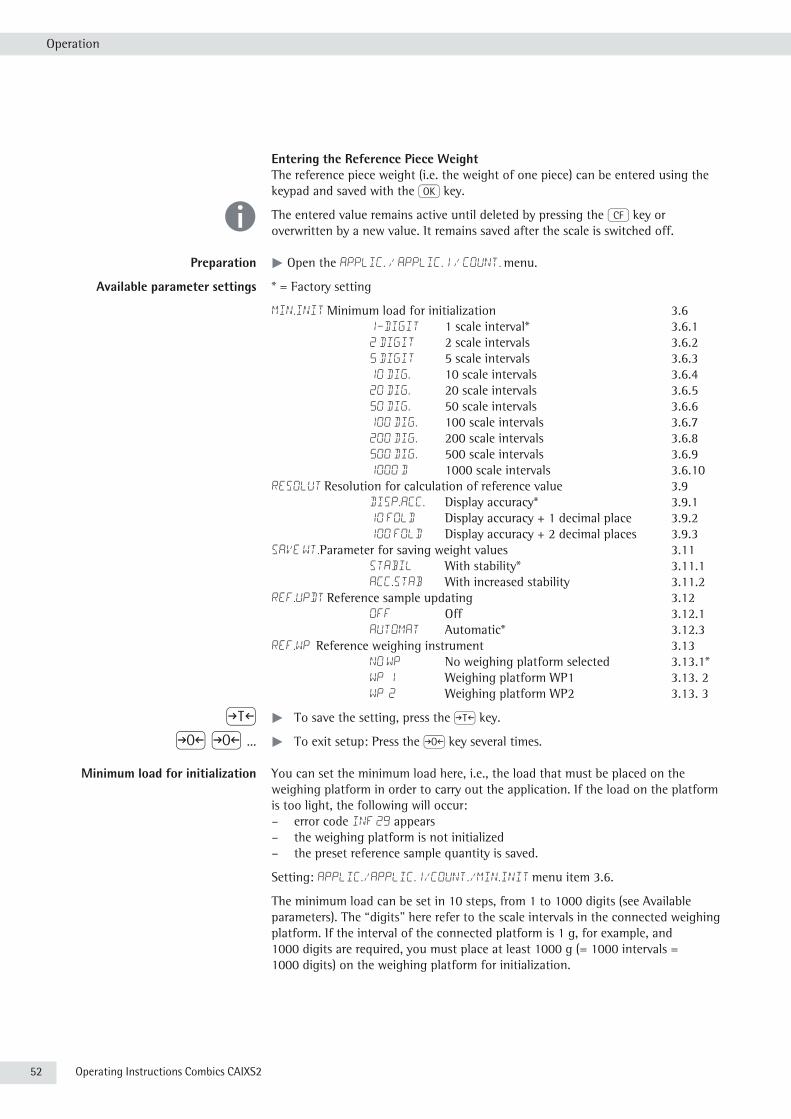
52 Operating Instructions Combics CAIXS2
Operation
Entering the Reference Piece Weight The reference piece weight (i.e. the weight of one piece) can be entered using the keypad and saved with the O key.
h The entered value remains active until deleted by pressing the c key or overwritten by a new value. It remains saved after the scale is switched off.
Preparation t Open the APPLIC. / APPLIC.1 / COUNT. menu.
Available parameter settings * = Factory setting
MIN.INIT Minimum load for initialization 3.6 1-digit 1 scale interval* 3.6.1 2 digit 2 scale intervals 3.6.2 5 digit 5 scale intervals 3.6.3 10 dig. 10 scale intervals 3.6.4 20 dig. 20 scale intervals 3.6.5 50 dig. 50 scale intervals 3.6.6 100 dig. 100 scale intervals 3.6.7 200 dig. 200 scale intervals 3.6.8 500 dig. 500 scale intervals 3.6.9 1000 d 1000 scale intervals 3.6.10RESOLUT Resolution for calculation of reference value 3.9 Disp.acc. Display accuracy* 3.9.1 10 FOLD Display accuracy + 1 decimal place 3.9.2 100 FOLD Display accuracy + 2 decimal places 3.9.3SAVE WT.Parameter for saving weight values 3.11 STABIL With stability* 3.11.1 ACC.STAB With increased stability 3.11.2REF.UPDT Reference sample updating 3.12 OFF Off 3.12.1 AUTOMAT Automatic* 3.12.3REF.WP Reference weighing instrument 3.13 NO WP No weighing platform selected 3.13.1* WP 1 Weighing platform WP1 3.13. 2 WP 2 Weighing platform WP2 3.13. 3
) t To save the setting, press the ) key.
( ( ... t To exit setup: Press the ( key several times.
Minimum load for initialization You can set the minimum load here, i.e., the load that must be placed on the weighing platform in order to carry out the application. If the load on the platform is too light, the following will occur:– error code Inf 29 appears– the weighing platform is not initialized– the preset reference sample quantity is saved.
Setting: APPLIC./APPLIC.1/COUNT./MIN.INIT menu item 3.6.
The minimum load can be set in 10 steps, from 1 to 1000 digits (see Available parameters). The “digits" here refer to the scale intervals in the connected weighing platform. If the interval of the connected platform is 1 g, for example, and 1000 digits are required, you must place at least 1000 g (= 1000 intervals = 1000 digits) on the weighing platform for initialization.
Operating Instructions Combics CAIXS2 53
Operation
Resolution The resolution indicates the accuracy used to determine the reference weight. The default setting is “display resolution." The resolution is increased when “10-fold" or “100-fold" is selected. “10-fold" increases the resolution of the net value by one step (display resolution x 10), “100-fold" increases it two steps (display resolution x 100). Setting: APPLIC./APPLIC.1/COUNT./RESOLUT menu item 3.9.
Parameter for saving weight values The weight on the platform is saved as a reference value as soon as the platform has stabilized. “Stability" is defined as the point at which the fluctuation of a measured value lies within a defined tolerance. The narrower the tolerance, the more stable the platform is at “stability".The “increased stability" setting has a lower tolerance so that the average piece weight saves is more accurate and the results more reproducible; however, the measurement time can take longer. Setting: APPLIC./APPLIC.1/COUNT./SAVE WT. menu item 3.11.
Reference sample updating You can define whether or not the reference sample weight is updated automatically during weighing using this setting. The reference sample weight is updated automatically only when the following criteria are met:
1. “Automatic" must be set for reference sample updating in the menu.2. The current piece count exceeds the original piece count by at least two.3. The current piece count cannot be more than double the size of the original
piece count. This limitation does not apply to the first update if the piece weight was entered via a keypad.
4. The current piece count is less than 1000.5. The internally calculated piece count (such as 17.24 pcs) differs by less than
± 0.3 pcs from the nearest whole number (in this example: 17).6. The weighing platform is stable in accordance with the parameter defined for
saving weights.
If automatic reference sample updating is selected in the menu and the piece count (pcs) is displayed, the Auto symbol is displayed below the bar graph. If the reference sample weight has been updated since you began weighing, the text line shows the 0ptsymbol. During an updating operation, 0pt and the updated piece count are displayed briefly in the measured value line. The new reference sample weight and reference sample quantity are saved. Setting: APPLIC./APPLIC.1/COUNT./REF.UPDT menu item 3.12.
Counting with two weighing platforms You can use two weighing platforms simultaneously with the Counting application. When using two platforms, you can choose from the following operating modes:– Counting with two platforms of the same type– Counting with one reference platform and one weighing platform.
Counting with Two Platforms of the Same TypeUse this mode to count different types of sample material with different weights. For example, count the lighter-weight pieces on one platform and the heavier pieces on another. You can define one of the two scales as the reference scale. The reference scale is the first scale active when you switch on the device, regardless of the setting for automatic initialization of the Counting application.
Counting with One Reference Platform and One Weighing PlatformIn this operating mode, the reference platform is a high-resolution weighing platform with a relatively low maximum capacity. The other platform is used for weighing heavier samples, and has a high capacity with a relatively low resolution. This allows you to both determine the reference sample weight with high resolution; i.e., very precisely, and to count large amounts of parts, without requiring an expensive high-resolution, high-capacity weighing platform.

54 Operating Instructions Combics CAIXS2
Operation
The system can be configured to switch automatically to the reference platform for initialization (the measured value line shows Ref). Following initialization, you can switch to the counting platform. Setting: APPLIC./APPLIC.1/COUNT./REF.WP menu item 3.13.
h If automatic reference sample updating is enabled, the update is performed on the active platform; in other words, the system does not automatically switch to the reference platform.
Example: You need to determine an unknown number of parts and the measurements should be logged.Configuration: The “Counting" application is selected, and printout has been set up.
t Place empty container on the scale.
) t Tare the scale. This is not required if the automatic tare function is active. The tare weight is saved automatically when you place the container on the platform.
t Place any number of parts in the container for the reference quantity (in this example, 20 pcs).
2 0 t Enter the number of parts using the keypad.
r t Start the calculation of the reference piece weight.
r t Set the number of reference parts using r: 1, 2, 5, 10, 20, etc.
O t Start the calculation of the reference piece weight.
t Add a quantity of uncounted parts to the container.
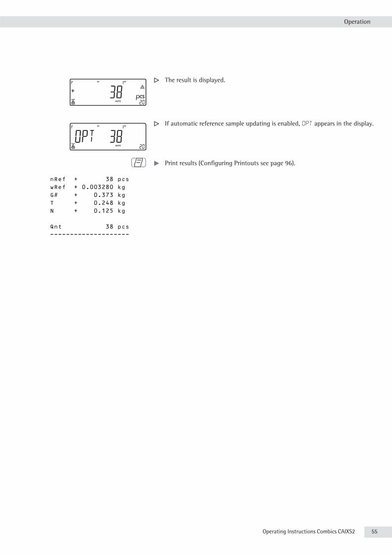
Operating Instructions Combics CAIXS2 55
Operation
y The result is displayed.
y If automatic reference sample updating is enabled, Opt appears in the display.
p t Print results (Configuring Printouts see page 96).
nRef + 38 pcs wRef + 0.003280 kg G# + 0.373 kg T + 0.248 kg N + 0.125 kg
Qnt 38 pcs --------------------

56 Operating Instructions Combics CAIXS2
Operation
Neutral Measurement Z nM
With this application you can measure the length, surface and volume of parts that have roughly the same specific weight. The o symbol is displayed as the unit (menu APPLIC.1).
Features – Save the reference weight “wRef" from the weighing platform.– Enter the reference weight “wRef" using the keypad.– Enter the factor for calculation “nRef” using the keypad.– Measuring with two weighing platforms.– Activate Info mode with the I key.– Toggle the display between measurement and weight using the w key.– The level of accuracy (display resolution) can be set when the calculated
reference weight is applied.– Automatic taring of container weight.
Setting: Applic./aut.tare, menu item 3.7.– Automatic initialization when the scale is switched on. The indicator is
initialized with the most recently used values for reference sample quantity “nRef” and reference sample weight “wRef.” Setting: Applic./aut.strt, menu item 3.8 .
Exit Application, Delete Parameters The value of the reference sample weight in the reference memory remains active until it is deleted using the c key, or is overwritten, or until the application is changed. The reference sample weight also remains saved after the scale is turned off. You can assign different functions to the c to delete applications. When you clear applications, you can delete either the data stored for all applications or just selected data stored for the active application. Setting: APPLIC/CLER.CF menu item 3.24.
Tare Function:If you store a tare (weight value) by pressing the ) key, you can later enter a tare value manually. The tare value you enter is added to the stored tare value. Setting: APPLIC./TARE.FNC menu item 3.25.1 (factory setting).
A tare value entered manually overwrites a stored tare value (weight value). If you enter a tare value manually, a tare value (weight value) stored later overwrites the manually entered value. Setting: Applic./TARE.FNC menu item 3.25.2.
Restore factory default settings: Applic./Reset menu item 9.1.
Reference WeightIn order to calculate the length, surface or volume of a given sample, the average weight of a reference quantity of the sample must be known (in the example below, the reference is 1 meter of electrical cable). There are different ways to enter the reference weight: Calculating the Reference Weight- Place the reference quantity (defined by the calculation factor) on the
connected weighing platform and calculate the reference sample weight by pressing the O key.
or- Place any amount of the sample material on the connected weighing platform,
enter the calculation factor through the keypad, and press the r key to calculate the reference sample weight.
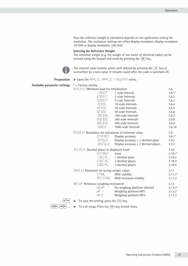
Operating Instructions Combics CAIXS2 57
Operation
How the reference weight is calculated depends on the application setting for resolution. The resolution settings are either display resolution, display resolution 10-fold or display resolution 100-fold.
Entering the Reference WeightThe reference weight (e.g. the weight of one meter of electrical cable) can be entered using the keypad and saved by pressing the O key.
h The entered value remains active until deleted by pressing the c key or overwritten by a new value. It remains saved after the scale is switched off.
Preparation t Open the APPLIC./APPLIC.1/Neutr.M. menu.
Available parameter settings * = Factory settingMIN.INIT Minimum load for initialization 3.6 1 digit 1 scale interval 3.6.1* 2 digit 2 scale intervals 3.6.2 5 digit 5 scale intervals 3.6.3 10 dig. 10 scale intervals 3.6.4 20 dig. 20 scale intervals 3.6.5 50 dig. 50 scale intervals 3.6.6 100 dig. 100 scale intervals 3.6.7 200 dig. 200 scale intervals 3.6.8 500 dig. 500 scale intervals 3.6.9 1000 d 1000 scale intervals 3.6.10
RESOLUT Resolution for calculation of reference value 3.9 Disp.acc. Display accuracy 3.9.1* 10 FOLD Display accuracy + 1 decimal place 3.9.2 100 FOLD Display accuracy + 2 decimal places 3.9.3
Dec.plcs Decimal places in displayed result 3.10 without none 3.10.1* 1 Dec.Pl. 1 decimal place 3.10.2 2 Dec.Pl. 2 decimal places 3.10.3 3 Dec.Pl. 3 decimal places 3.10.4
SAVE WT.Parameter for saving weight values 3.11 STABL. With stability 3.11.1* ACC.STAB With increased stability 3.11.2
REF.WP Reference weighing instrument 3.13 NO WP No weighing platform selected 3.13.1* WP 1 Weighing platform WP1 3.13.2 WP 2 Weighing platform WP2 3.13.3
) t To save the setting, press the ) key.
( ( ... t To exit setup: Press the ( key several times.

58 Operating Instructions Combics CAIXS2
Operation
Minimum load for initialization You can set the minimum load here, i.e., the load that must be placed on the weighing platform in order to carry out the application. If the load on the platform is too light, the following will occur:– error code Inf 29 appears– the weighing platform is not initialized– the preset reference sample quantity is saved.
Setting: Applic./Applic.1/neutr.m/Min.init menu item 3.6.
The minimum load can be set in 10 steps, from 1 to 1000 digits (see Available parameters). The “digits" here refer to the scale intervals in the connected weighing platform. If the interval of the connected platform is 1 g, for example, and 1000 digits are required, you must place at least 1000 g (= 1000 intervals = 1000 digits) on the weighing platform for initialization.
Resolution The resolution indicates the accuracy used to determine the reference weight. The default setting is “display resolution." The resolution is increased when “10-fold" or “100-fold" is selected. “10-fold" increases the resolution of the net value by one step (display resolution x 10), “100-fold" increases it two steps (display resolution x 100). Setting: Applic./Applic.1/neutr.m/RESOLUT menu item 3.9.
Decimal places In neutral measurement, not only whole numbers but also decimal numbers (for example, 1.25 o electrical cabling) can be displayed. The number of decimal places displayed can range from none up to 3 places. Setting: Applic./Applic.1/neutr.m/DEC.PLCS menu item 3.10.
Parameter for saving weight values The weight on the platform is saved as a reference value as soon as the platform has stabilized. “Stability" is defined as the point at which the fluctuation of a measured value lies within a defined tolerance. The narrower the tolerance, the more stable the platform is at “stability".The “increased stability" setting has a lower tolerance so that the average piece weight saves is more accurate and the results more reproducible; however, the measurement time can take longer. Setting: Applic./Applic.1/neutr.m/SAVE WT. menu item 3.11.
Measuring with two weighing platforms You can use two weighing platforms simultaneously with the Neutral Measurement application. When using two platforms, you can choose from the following operating modes:– Counting with two platforms of the same type– Counting with one reference platform and one weighing platform.
Neutral Measurement with Two Platforms of the Same TypeUse this mode to measure different types of sample material with different weights. For example, measure the lighter-weight samples on one platform and the heavier samples on another. You can define one of the two scales as the reference scale. The reference scale is the first scale active when you switch on the device, regardless of the setting for automatic initialization of the Neutral Measurement application.
Neutral Measurement with One Reference Platform and One Weighing PlatformIn this operating mode, the reference platform is a high-resolution weighing platform with a relatively low maximum capacity. The other platform is used for weighing heavier samples, and has a high capacity with a relatively low resolution.This allows you to both determine the reference piece weight with high resolution; i.e., very precisely, and to measure large samples, without requiring an expensive high-resolution, high-capacity weighing platform.The system can be configured to switch automatically to the reference platform for initialization (the measured value line shows Ref).

Operating Instructions Combics CAIXS2 59
Operation
Following initialization, you can switch to the counting platform. Example: 25 m of electrical cable is to be measured.
Configuration: The “Neutral Measurement" application is selected, and printout has been set up (see “Configuration").
t Place empty container on the scale.
) t Tare the scale. This is not required if the automatic tare function is active. The tare weight is saved automatically when you place the container on the platform.
2 4 8 t Enter the weight of 1 meter of cable using the keypad (in this example, 248 g).
O t Save the value entered.
or
r t Set the number of reference parts using r: 1, 2, 5, 10, 20, etc.
O t Start the calculation of the reference piece weight.
t Place the desired amount of cable into the container (25 m in this example).
y The result is displayed.
p t Print results (Configuring Printouts).
nRef + 1 o wRef + 0.248 kg
G# + 6.794 kg T + 0.541 kg N + 6.253 kg
Qnt 25 o --------------------

60 Operating Instructions Combics CAIXS2
Operation
Averaging (Animal Weighing) VWith this application, you can calculate averages from several weighing operations. It is used when either the object to be weighed (e.g. animals) or the environment during weighing are unstable. Selection and settings in the Applic. / Applic.1 /
ANIM.WG menu.
Features – Averaging started manually or automatically (... /start menu item 3.18). With manual start selected, the averaging routine begins when you press a key (provided the start conditions are met). With automatic start selected, the application begins when you place the first load on the platform (provided the start conditions are met).
– Enter the number of subweighing operations using the keypad.– Use the r key to select the number of measurements for averaging.– Activate Info mode with the I key.– Toggle the display between “result of last measurement” and “current weight”
by pressing the w key.– Automatic printout of results (... /PRINT menu item 3.20). – Automatic taring of container weight (APPLIC./aut.tare menu item 3.7).– Automatic start of averaging when the scale is turned on and a sample placed
on the platform, provided start conditions are met (APPLIC./aut.Strt menu item 3.8).
Exit Application, Delete Parameters The value of the reference sample weight in the reference memory remains active until it is deleted using the c key, or is overwritten, or until the application is changed. The reference sample weight also remains saved after the scale is turned off. You can assign different functions to the c to delete applications. When you clear applications, you can delete either the data stored for all applications or just selected data stored for the active application. Setting: APPLIC/CLER.CF menu item 3.24.
Tare Function:If you store a tare (weight value) by pressing the ) key, you can later enter a tare value manually. The tare value you enter is added to the stored tare value. Setting: APPLIC./TARE.FNC menu item 3.25.1 (factory setting).
A tare value entered manually overwrites a stored tare value (weight value). If you enter a tare value manually, a tare value (weight value) stored later overwrites the manually entered value. Setting: Applic./TARE.FNC menu item 3.25.2.
Restore factory default settings: Applic./Reset menu item 9.1.
Number of measurements for averaging You can enter the desired number of weight measurements to determine the average using the keypad. This value remains active until it is overwritten by another value. It also remains in memory when you switch to a different application program, or turn off the scale.
Start application There are three ways to start the averaging routine:– Manual start with preset number of subweighing operations: Place the sample
on the platform and press the O key.

Operating Instructions Combics CAIXS2 61
Operation
– Manual start with user-defined number of subweighing operations: Place the sample on the platform and enter the number of weighing operations using the keypad. Press the r key to save the number entered and begin weighing.
– Automatic start with preset number of subweighing operations: Measurement begins when you place the first sample on the platform, provided the start conditions are met.
Preparation t Open the APPLIC./APPLIC.1/ANIM.WGmenu.
Available parameter settings * = Factory settingMIN.INIT Minimum load for initialization 3.6 1-digit 1 scale interval* 3.6.1 2 digit 2 scale intervals 3.6.2 5 digit 5 scale intervals 3.6.3 10 dig. 10 scale intervals 3.6.4 20 dig. 20 scale intervals 3.6.5 50 dig. 50 scale intervals 3.6.6 100 dig. 100 scale intervals 3.6.7 200 dig. 200 scale intervals 3.6.8 500 dig. 500 scale intervals 3.6.9 1000 d 1000 scale intervals 3.6.10
START Start averaging 3.18 manual Manual* 3.18.1 AUTOMAT Automatic 3.18.2
ACTIVTY Animal activity 3.19 0.1 perc. 0.1% of animal/object 3.19.1 0.2 perc. 0.2% of animal/object* 3.19.2 0.5 perc. 0.5% of animal/object 3.19.3 1 PERC. 1% of animal/object 3.19.4 2 PERC. 2% of animal/object 3.19.5 5 PERC. 5% of animal/object 3.19.6 10 PERC. 10% of animal/object 3.19.7 20 PERC. 20% of animal/object 3.19.8 50 PERC. 50% of animal/object 3.19.9 100 PERC. 100% of animal/object 3.19.10
PRINT Autom. printout of results 3.20 manual Off* 3.20.1 automat On 3.20.2
DIS.UNLD Static display of result after load removed 3.21 CLEARED Display is fixed until 3.21.1 unload threshold reached* PRESENT Fixed display until c is pressed 3.21.2
) t To save the setting, press the ) key.
( ( ... t To exit setup: Press the ( key several times.
Minimum load for initialization You can set the minimum load here, i.e., the load that must be placed on the weighing platform in order to carry out the application. If the load on the platform is too light, the following will occur:– error code Inf 29 appears– the weighing platform is not initialized– the preset reference sample quantity is saved.
Setting: Applic./Applic.1/ANIM.WG/Min.init menu item 3.6.
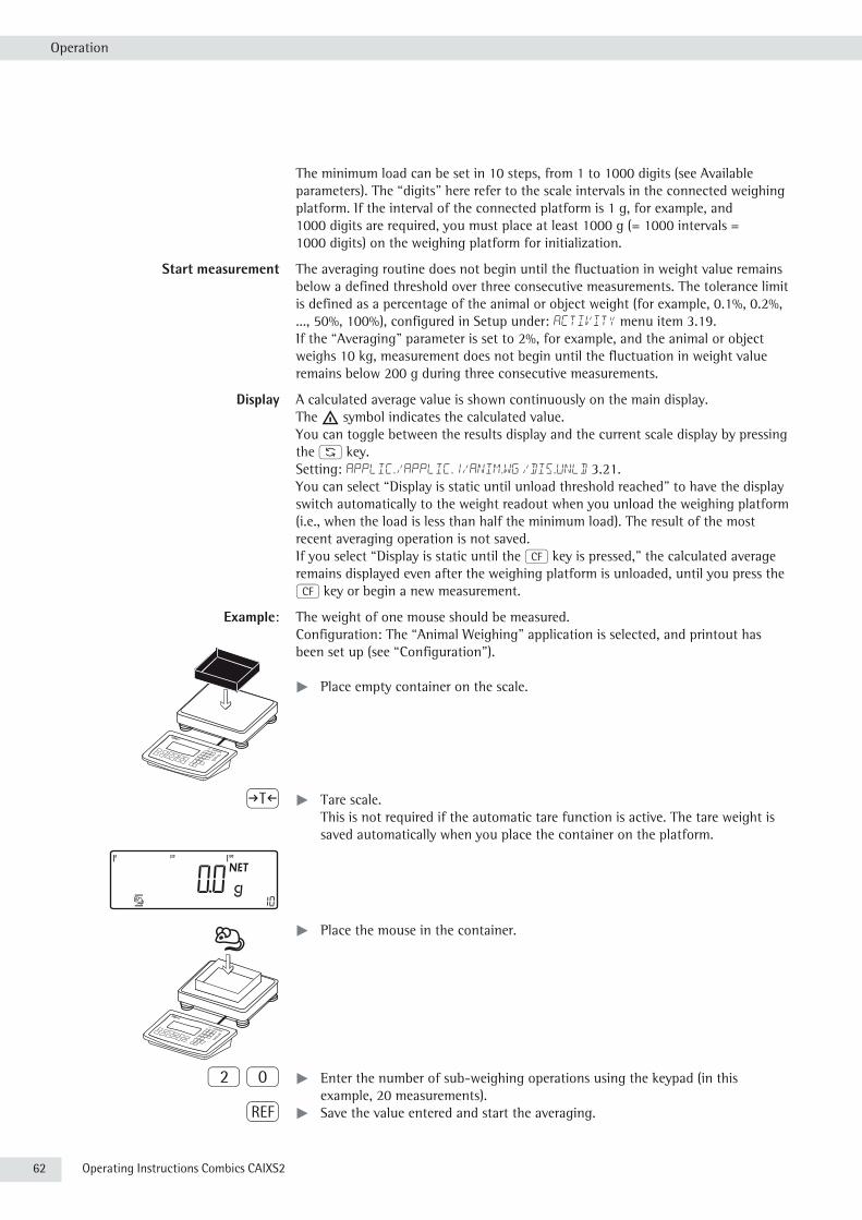
62 Operating Instructions Combics CAIXS2
Operation
The minimum load can be set in 10 steps, from 1 to 1000 digits (see Available parameters). The “digits" here refer to the scale intervals in the connected weighing platform. If the interval of the connected platform is 1 g, for example, and 1000 digits are required, you must place at least 1000 g (= 1000 intervals = 1000 digits) on the weighing platform for initialization.
Start measurement The averaging routine does not begin until the fluctuation in weight value remains below a defined threshold over three consecutive measurements. The tolerance limit is defined as a percentage of the animal or object weight (for example, 0.1%, 0.2%, ..., 50%, 100%), configured in Setup under: Activity menu item 3.19.If the “Averaging” parameter is set to 2%, for example, and the animal or object weighs 10 kg, measurement does not begin until the fluctuation in weight value remains below 200 g during three consecutive measurements.
Display A calculated average value is shown continuously on the main display. The G symbol indicates the calculated value.You can toggle between the results display and the current scale display by pressing the w key.Setting: APPLIC./APPLIC.1/ANIM.WG /DIS.UNLD 3.21.You can select “Display is static until unload threshold reached” to have the display switch automatically to the weight readout when you unload the weighing platform (i.e., when the load is less than half the minimum load). The result of the most recent averaging operation is not saved.If you select “Display is static until the c key is pressed," the calculated average remains displayed even after the weighing platform is unloaded, until you press the c key or begin a new measurement.
Example: The weight of one mouse should be measured.Configuration: The “Animal Weighing" application is selected, and printout has been set up (see “Configuration").
t Place empty container on the scale.
) t Tare scale. This is not required if the automatic tare function is active. The tare weight is saved automatically when you place the container on the platform.
t Place the mouse in the container.
2 0 t Enter the number of sub-weighing operations using the keypad (in this example, 20 measurements).
r t Save the value entered and start the averaging.
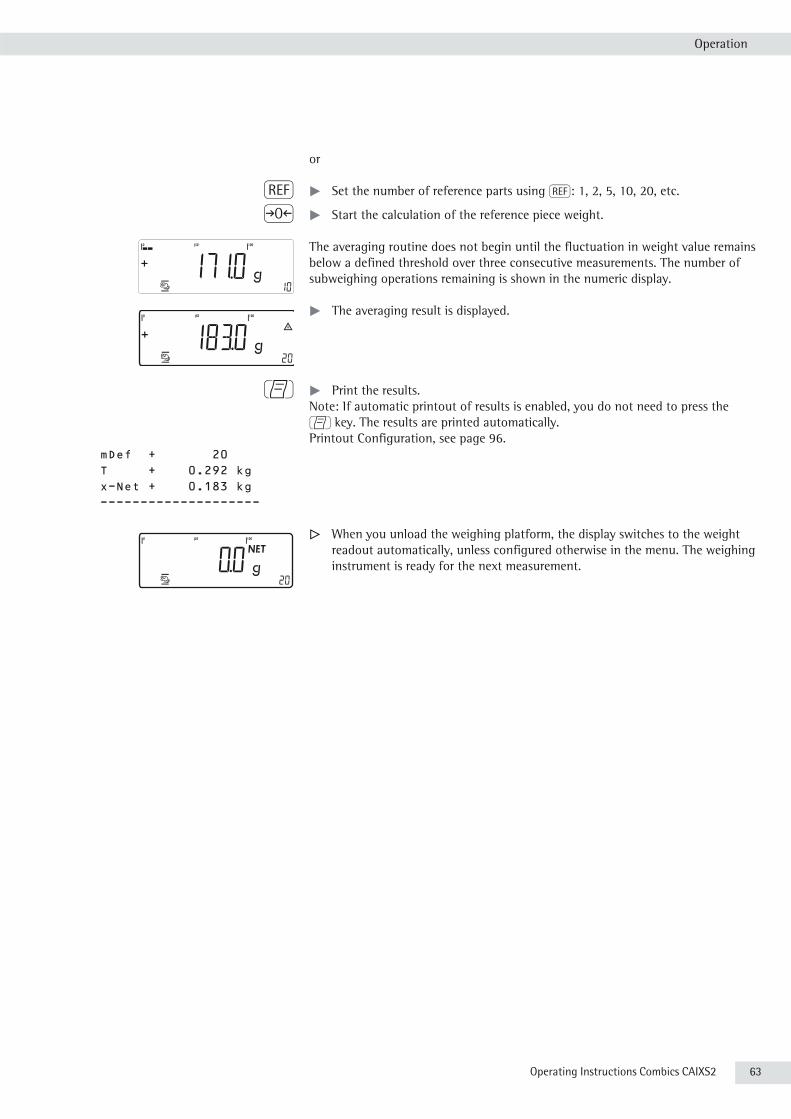
Operating Instructions Combics CAIXS2 63
Operation
or
r t Set the number of reference parts using r: 1, 2, 5, 10, 20, etc.
( t Start the calculation of the reference piece weight.
The averaging routine does not begin until the fluctuation in weight value remains below a defined threshold over three consecutive measurements. The number of subweighing operations remaining is shown in the numeric display.
t The averaging result is displayed.
p t Print the results. Note: If automatic printout of results is enabled, you do not need to press the p key. The results are printed automatically.Printout Configuration, see page 96.
mDef + 20 T + 0.292 kg x-Net + 0.183 kg -------------------- y When you unload the weighing platform, the display switches to the weight
readout automatically, unless configured otherwise in the menu. The weighing instrument is ready for the next measurement.
64 Operating Instructions Combics CAIXS2
Operation
Weighing in Percent LWith this application, you can use your weighing platform to obtain weight readouts in percent which are in proportion to a reference weight. L is displayed as the weight unit. Selection and settings in the Applic. / Applic.1 / PERCENT menu.
Features – Save the current weight value as reference weight “pRef”.– Enter the reference weight “Wxx%” for 100% using the keypad. – Enter the reference percentage “pRef” using the keypad.– Display result as loss (difference) or residue. – Display up to 3 decimal places (menu item 3.10). – Weighing in percent with two weighing platforms.– Activate Info mode with the I key.– Toggle between percent display and weight display using the w key.– Automatic taring of container weight (APPLIC. /aut.tare menu item 3.7).– Automatic initialization when the scale is switched on. The application is
initialized with the most recently used data (APPLIC. / aut.Strt menu item 3.8).
Exit Application, Delete Parameters The value of the reference sample weight in the reference memory remains active until it is deleted using the c key, or is overwritten, or until the application is changed. The reference sample weight also remains saved after the scale is turned off. You can assign different functions to the c key to delete applications. When you clear applications, you can delete either the data stored for all applications or just selected data stored for the active application. Setting: APPLIC/CLER.CF menu item 3.24.
Tare Function:If you store a tare (weight value) by pressing the ) key, you can later enter a tare value manually. The tare value you enter is added to the stored tare value. Setting: APPLIC./TARE.FNC menu item 3.25.1 (factory setting). A tare value entered manually overwrites a stored tare value (weight value). If you enter a tare value manually, a tare value (weight value) stored later overwrites the manually entered value. Setting: Applic./TARE.FNC menu item 3.25.2.
Restore factory default settings: Applic./Reset menu item 9.1.
To determine the weight of a sample relative to a reference weight, you need to define the reference percentage value. There are different ways to enter this value in the application:
Calculating the Reference Percentage Value- Place the reference quantity (defined by the reference percentage value) on the
connected weighing platform and press the O key to initialize the application.or- Place any amount of the sample material on the connected weighing platform,
enter the reference percentage value through the keypad, and press the r key to initialize the application.
How the reference weight is calculated depends on the application setting that defines “Accuracy for saving weights”. The value is either rounded off in accordance with the display resolution, saved with 10-fold or 100-fold resolution.

Operating Instructions Combics CAIXS2 65
Operation
Entering the Reference Percentage ValueThe reference weight for 100% is entered using the keypad and the O key is pressed to initialize the application.
h The entered value remains active until deleted by pressing the c key or overwritten by a new value. It remains saved after the scale is switched off.
Preparation t Open the APPLIC./APPLIC.1/PERCENT menu.
Available parameter settings * = Factory settingMIN.INIT Minimum load for initialization 3.6 1-digit 1 scale interval* 3.6.1 2 digit 2 scale intervals 3.6.2 5 digit 5 scale intervals 3.6.3 10 dig. 10 scale intervals 3.6.4 20 dig. 20 scale intervals 3.6.5 50 dig. 50 scale intervals 3.6.6 100 dig. 100 scale intervals 3.6.7 200 dig. 200 scale intervals 3.6.8 500 dig. 500 scale intervals 3.6.9 1000 d 1000 scale intervals 3.6.10
RESOLUT Resolution for calculation of reference value 3.9 Disp.acc. Display accuracy 3.9.1* 10 FOLD Display accuracy + 1 decimal place 3.9.2 100 FOLD Display accuracy + 2 decimal places 3.9.3
Dec.plcs Decimal places in displayed result 3.10 without none 3.10.1* 1 Dec.Pl. 1 decimal place 3.10.2 2 Dec.Pl. 2 decimal places 3.10.3 3 Dec.Pl. 3 decimal places 3.10.4
SAVE WT.Parameter for saving weight values 3.11 STABL. With stability 3.11.1* ACC.STAB With increased stability 3.11.2
REF.WP Reference weighing instrument 3.13 NO WP No weighing platform selected 3.13.1* WP 1 Weighing platform WP1 3.13.2 WP 2 Weighing platform WP2 3.13.3
CALC.DIS Calculated values display 3.15 RESIDUE Residue 3.15.1* LOSS Loss 3.15.2
) t To save the setting, press the ) key.
( ( ... t To exit setup: Press the ( key several times.
Minimum load for initialization You can set the minimum load here, i.e., the load that must be placed on the weighing platform in order to carry out the application. If the load on the platform is too light, the following will occur:– error code Inf 29 appears– the weighing platform is not initialized– the preset reference sample quantity is saved.
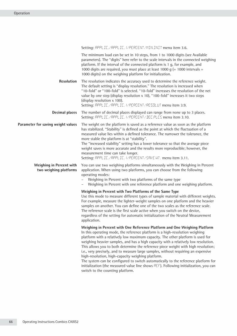
66 Operating Instructions Combics CAIXS2
Operation
Setting: Applic./Applic.1/PERCENT/Min.init menu item 3.6.
The minimum load can be set in 10 steps, from 1 to 1000 digits (see Available parameters). The “digits" here refer to the scale intervals in the connected weighing platform. If the interval of the connected platform is 1 g, for example, and 1000 digits are required, you must place at least 1000 g (= 1000 intervals = 1000 digits) on the weighing platform for initialization.
Resolution The resolution indicates the accuracy used to determine the reference weight. The default setting is “display resolution." The resolution is increased when “10-fold" or “100-fold" is selected. “10-fold" increases the resolution of the net value by one step (display resolution x 10), “100-fold" increases it two steps (display resolution x 100). Setting: Applic./Applic.1/PERCENT/RESOLUT menu item 3.9.
Decimal places The number of decimal places displayed can range from none up to 3 places. Setting: Applic./Applic.1/PERCENT/DEC.PLCS menu item 3.10.
Parameter for saving weight values The weight on the platform is saved as a reference value as soon as the platform has stabilized. “Stability" is defined as the point at which the fluctuation of a measured value lies within a defined tolerance. The narrower the tolerance, the more stable the platform is at “stability".The “increased stability" setting has a lower tolerance so that the average piece weight saves is more accurate and the results more reproducible; however, the measurement time can take longer. Setting: APPLIC./APPLIC.1/PERCENT/SAVE WT. menu item 3.11.
Weighing in Percent with You can use two weighing platforms simultaneously with the Weighing in Percent two weighing platforms application. When using two platforms, you can choose from the following
operating modes:– Weighing in Percent with two platforms of the same type– Weighing in Percent with one reference platform and one weighing platform.
Weighing in Percent with Two Platforms of the Same TypeUse this mode to measure different types of sample material with different weights. For example, measure the lighter-weight samples on one platform and the heavier samples on another. You can define one of the two scales as the reference scale. The reference scale is the first scale active when you switch on the device, regardless of the setting for automatic initialization of the Neutral Measurement application.
Weighing in Percent with One Reference Platform and One Weighing PlatformIn this operating mode, the reference platform is a high-resolution weighing platform with a relatively low maximum capacity. The other platform is used for weighing heavier samples, and has a high capacity with a relatively low resolution.This allows you to both determine the reference piece weight with high resolution; i.e., very precisely, and to measure large samples, without requiring an expensive high-resolution, high-capacity weighing platform.The system can be configured to switch automatically to the reference platform for initialization (the measured value line shows Ref). Following initialization, you can switch to the counting platform.

Operating Instructions Combics CAIXS2 67
Operation
Example: 100% of a sample material should be weighed.Configuration: The “Weighing in percent" application is selected, and printout has been set up.
t Place empty container on the scale.
) t Tare the scale. This is not required if the automatic tare function is active. The tare weight is saved automatically when you place the container on the platform.
t Add reference material to the container in accordance with reference percentage value (in this example, 85 g).
O t Start the calculation of the reference weight by pressing the O key.
y The calculation is based on the active net weight value and the reference percentage value entered.
If the weight is too light, an error code is shown in the main display Inf 29. If this is the case, set the minimum load to a smaller number of digits.
t Add additional material until the reference percentage value has been reached (in this example, 100 g).
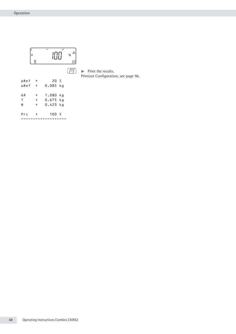
68 Operating Instructions Combics CAIXS2
Operation
p t Print the results. Printout Configuration, see page 96.
pRef + 20 % wRef + 0.085 kg
G# + 1.080 kg T + 0.675 kg N + 0.423 kg
Prc + 100 % -------------------

Operating Instructions Combics CAIXS2 69
Operation
Checkweighing H With this application, you can check whether the sample on the weighing platform matches a target value or lies within a given tolerance range. Checkweighing also makes it easy to fill sample materials to a specified target weight. Selection and settings in the Applic. / Applic.2/ CHECK.WG menu.
Features – Enter the nominal or target weight (set point) and the tolerance range delimiters either using the keypad or by saving the weight value of a load on the platform.
– Enter the tolerance limits as absolute values (Min and Max), as a percentage deviation from the target or as a relative deviation from the target. Setting: Applic./Applic.2/CHECK.WG/CHECK.RG menu item 4.5.
– The target value can be taken over as a weighed value from a weighing platform, and the upper and lower tolerance limits are defined as a percentage deviation from the target value (setting 4.5.2). The following percentages can be selected as the deviation: 0.1%, 0.2%, 0.5%, 1%, 1.5%, 2%, 3%, 5% or 10%, selection using the r key.
– The target value, lower tolerance limit (minimum) and upper tolerance limit (maximum) can applied as weighed values from the weighing platform (menu item 4.5.1).
– The target value can be applied as weighed values and via asymmetrical percent limits (menu item 4.5.3).
– The target value can be applied as weighed values and via relative weight limits (menu item 4.5.4).
– Target value and tolerance limits checked during input; values must conform to: upper limit > target > lower limit > 1 digit.
– Checkweighing range: either 30% to 170% of the target, or from 10% to infinity.
– Results are shown on the main display, as a bar graph and LED as well as sent to control output ports for further processing.
– Toggle the main display between weight and tolerances limits by pressing the w key. If the weight in the readout is outside the tolerance range, “LL" (too low) or “HH" (too high) is displayed.
– Activate Info mode with the I key.– Automatic results printout (Applic./Applic.2/CHECK.WG/CHECK.RG menu
item 4.6).– Automatic taring of container weight (APPLIC./ aut.tare menu item 3.7).– Automatic initialization when you switch on the scale with most recently saved
application data (APPLIC./aut.Strt menu item 3.8).
You can assign different functions to the c key to delete applications. When you clear applications, you can delete either the data stored for all applications or just selected data stored for the active application. Setting: APPLIC/CLER.CF menu item 3.24.
Tare Function:If you store a tare (weight value) by pressing the ) key, you can later enter a tare value manually. The tare value you enter is added to the stored tare value. Setting: APPLIC./TARE.FNC menu item 3.25.1 (factory setting).
70 Operating Instructions Combics CAIXS2
Operation
A tare value entered manually overwrites a stored tare value (weight value). If you enter a tare value manually, a tare value (weight value) stored later overwrites the manually entered value. Setting: Applic./TARE.FNC menu item 3.25.2.
Restore factory default settings: Applic./Reset menu item 9.1.
Target value Checkweighing entails comparing the current weight value to a defined target value. You can enter the value for this target using the keypad, or by saving the weight value indicated. You can also define upper and lower tolerance limits based on this target. You can do this by:– entering absolute values using the keypad or placing the desired amount of
weight on the platform and saving the value or– by entering each value using the keypad as a percentage deviation of the target
weightor– by entering each value as an asymmetrical percentage deviation of the target
weight that is selected via the keypad or using the r key or– by entering a relative weight deviation from the target weight via the keypad.
The value remains valid until deleted by pressing the c key or until overwritten by a new value. It remains saved after the scale is switched off.
Preparation t Open the APPLIC./APPLIC.2/CHECK.WG menu.
Available Parameter Settings * = Factory settingMIN.INIT Minimum load for initialization 3.5 1 digit 1 scale interval 3.5.1* 2 digit 2 scale intervals 3.5.2 5 digit 5 scale intervals 3.5.3 10 dig. 10 scale intervals 3.5.4 20 dig. 20 scale intervals 3.5.5 50 dig. 50 scale intervals 3.5.6 100 dig. 100 scale intervals 3.5.7 200 dig. 200 scale intervals 3.5.8 500 dig. 500 scale intervals 3.5.9 1000 d 1000 scale intervals 3.5.10
Aut.strt Automat. Automatic start of applications when you switch on the device with most recently saved application data 3.8 AUTOMAT Automatic (on) 3.8.1 MANUAL Manual (off) 3.8.2
TARE.FNC Tare function 3.25 Normal Can add a preset tare if tare value is available; however no tare function possible 3.25.1* Special When a preset tare is entered, the tare value is deleted; however, tare function activation is possible 3.25.2
CHECK.RG Checkweighing range 4.2 30- 170% 30 to 170% 4.2.1* 10-MAX.L 10% to infinity 4.2.2

Operating Instructions Combics CAIXS2 71
Operation
CTRL.SET Activate SET control output 4.3 OUTPUT “SET" output 4.3.1* OP.READY Ready to operate 4.3.2
OUTP.ACT Port lines 4.4 OFF Off 4.4.1 ALWAYS Always on. 4.4.2 STABIL On at stability 4.4.3 CHECK.RG On within checkweighing range 4.4.4* STAB.CHK On at stability within checkweighing range 4.4.5
INPUT Parameter input 4.5 TAR.MN.MX Min, Max, target value 4.5.1* TARG.PER Only target value with percent limits 4.5.2 TAR.A.PER Target value with asymmetrical percent limits 4.5.3 TAR.TOL Target value with relative tolerances 4.5.4
AUT.PRNT Automatic printing 4.6 OFF Off 4.6.1* ON On 4.6.2 OK Only values within tolerance 4.6.3 NOT OK Only values outside tolerance 4.6.4
APP.ZERO Checkweighing toward zero 4.7 OFF Off 4.7.1* ON On 4.7.2
) t To save the setting, press the ) key.
( ( ... t To exit setup: Press the ( key several times.
Display The result of a measurement is shown either as a weight value or in relation to the target.Weight display: The measured value line always shows the weight value, even if it lies outside the tolerance range. The bar graph is displayed with symbols indicating lower limit, target and upper limit. Weights are shown logarithmically from 0 up to the lower tolerance limit, and linearly beyond that point.Relation to target value: As “Weight display" above, with the exception that: – LL appears in the main display if the weight value is less than the lower limit – HH is shown on the main display if the weight value is higher than the upper
tolerance limit.
Digital I|O Interface The Checkweighing application supports the digital input/output interface. The four outputs are activated as follows:– Less than > red LED lights up– Equal to > green LED lights up– Greater than > yellow LED lights up– Set.The outputs can also be galvanically isolated using option A5.
Acoustic signal: An acoustic signal can be activated in addition to the green LED. Setting: menu item 8.2.3.

72 Operating Instructions Combics CAIXS2
Operation
In the Applic./Applic.2/CHECK.WG/OUTP.ACT menu, menu item 4.4, you can choose the following settings for the control outputs: – off – always on – activated at stability – on within the checkweighing range – on at stability within checkweighing range.
Digital I|O Interface Digital I|O Interface – “SET" control output: set or ready for use – “SET" control output: set or ready for use
– port lines: always on – port lines: within the checkweighing range
The “SET” output normally changes its voltage level when the load is near the target weight. Alternatively, you can assign the “Ready for use” function to this port. Setting: Applic./Applic.2/CHECK.WG/CTRL.SET menu item 4.3.This makes it possible, for example, to connect a simple indicator for weighing or calculation results.All data output ports have a high voltage level when the application is not initialized.
Output port specifications:– When not in use, the voltage level is high: >3.7 V/+4 mA.– When activated, the voltage level is low: <0.4 V/–4 mA.
3
The outputs are not protected against short circuits and are not galvanically isolated.
Target weight
Checkweighing range
Lowertolerance limit
Uppertolerance limit
30 % 170%
Equal
Set
Lighter
Heavier
Ready for use
Set
Target weight
Lowertolerance limit
Uppertolerance limit
Checkweighing range30 % 170%
Equal
Ready for use
Lighter
Heavier
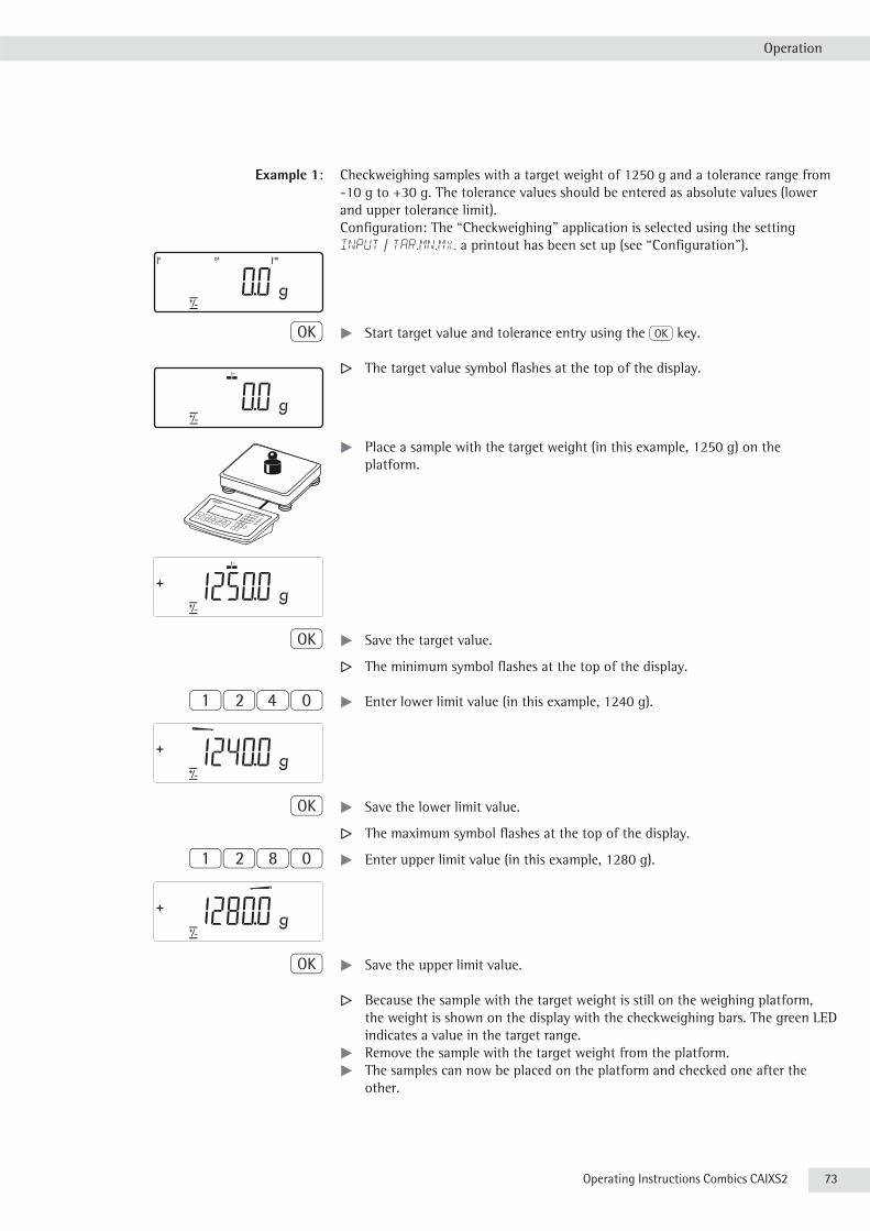
Operating Instructions Combics CAIXS2 73
Operation
Example 1: Checkweighing samples with a target weight of 1250 g and a tolerance range from -10 g to +30 g. The tolerance values should be entered as absolute values (lower and upper tolerance limit).Configuration: The “Checkweighing" application is selected using the setting INPUT / TAR.MN.MX, a printout has been set up (see “Configuration").
O t Start target value and tolerance entry using the O key.
y The target value symbol flashes at the top of the display.
t Place a sample with the target weight (in this example, 1250 g) on the platform.
O t Save the target value.
y The minimum symbol flashes at the top of the display.
1240 t Enter lower limit value (in this example, 1240 g).
O t Save the lower limit value.
y The maximum symbol flashes at the top of the display.
1280 t Enter upper limit value (in this example, 1280 g).
O t Save the upper limit value.
y Because the sample with the target weight is still on the weighing platform, the weight is shown on the display with the checkweighing bars. The green LED indicates a value in the target range.
t Remove the sample with the target weight from the platform.t The samples can now be placed on the platform and checked one after the
other.
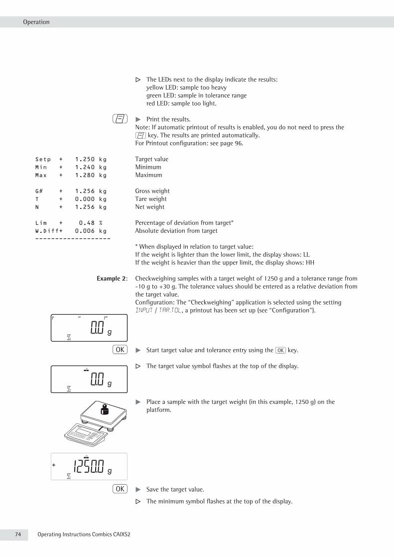
74 Operating Instructions Combics CAIXS2
Operation
y The LEDs next to the display indicate the results: yellow LED: sample too heavy green LED: sample in tolerance range red LED: sample too light.
p t Print the results. Note: If automatic printout of results is enabled, you do not need to press the p key. The results are printed automatically.For Printout configuration: see page 96.
Setp + 1.250 kg Target value Min + 1.240 kg Minimum Max + 1.280 kg Maximum
G# + 1.256 kg Gross weight T + 0.000 kg Tare weight N + 1.256 kg Net weight
Lim + 0.48 % Percentage of deviation from target* W.Diff+ 0.006 kg Absolute deviation from target -------------------
* When displayed in relation to target value:If the weight is lighter than the lower limit, the display shows: LLIf the weight is heavier than the upper limit, the display shows: HH
Example 2: Checkweighing samples with a target weight of 1250 g and a tolerance range from -10 g to +30 g. The tolerance values should be entered as a relative deviation from the target value.Configuration: The “Checkweighing" application is selected using the setting INPUT / TAR.TOL, a printout has been set up (see “Configuration").
O t Start target value and tolerance entry using the O key.
y The target value symbol flashes at the top of the display.
t Place a sample with the target weight (in this example, 1250 g) on the platform.
O t Save the target value.
y The minimum symbol flashes at the top of the display.

Operating Instructions Combics CAIXS2 75
Operation
10 t Enter the maximum lower deviation (in this example, 10 g).
O t Save the lower limit value.
y The maximum symbol flashes at the top of the display.
30 t Enter the maximum upper deviation (in this example, 30 g).
O t Save the upper limit value.
t Proceed as described in example 1.
Example 3: Checkweighing toward zero Y. Checkweighing samples with a target weight of 1250 g and a tolerance range from -10 g to +30 g.Configuration: The “Checkweighing toward zero" application (TOW.ZERO) is selected as well as the TAR.MN.MX entry, and a printout has been set up (see “Configuration").
O t Start target value and tolerance entry using the O key.
t Place a sample with the target weight (in this example, 1250 g) ontheplatform.
O t Save the target value.
1240 t Enter lower limit value (in this example, 1240 g).
O t Save the lower limit value.
1280 t Enter upper limit value (in this example, 1280 g).
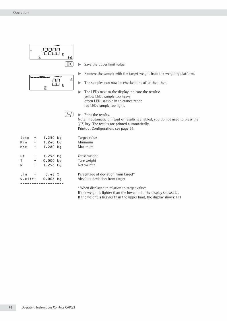
76 Operating Instructions Combics CAIXS2
Operation
O t Save the upper limit value.
t Remove the sample with the target weight from the weighing platform.
t The samples can now be checked one after the other.
y The LEDs next to the display indicate the results: yellow LED: sample too heavy green LED: sample in tolerance range red LED: sample too light.
p t Print the results. Note: If automatic printout of results is enabled, you do not need to press the p key. The results are printed automatically.Printout Configuration, see page 96.
Setp + 1.250 kg Target value Min + 1.240 kg Minimum Max + 1.280 kg Maximum
G# + 1.256 kg Gross weight T + 0.000 kg Tare weight N + 1.256 kg Net weight
Lim + 0.48 % Percentage of deviation from target* W.Diff+ 0.006 kg Absolute deviation from target -------------------
* When displayed in relation to target value:If the weight is lighter than the lower limit, the display shows: LLIf the weight is heavier than the upper limit, the display shows: HH

Operating Instructions Combics CAIXS2 77
Operation
Classification WWith this application, you can determine whether the weight of a given sample lies within the limits of a defined weight class (Applic.2 menu).
Features – Classification with 3 or 5 weight classes. Setting: Applic./Applic.2/CLASS./PARAM.2/QTY. menu item 4.8.
– Enter the upper limits of weight classes using the keypad or by saving weight values from a load on the platform.
– Enter the upper limits of weight classes as absolute values or as a percentage of deviation from the upper limit of Class 1. Setting: Applic./Applic.2/CLASS./PARAM.2/INPUT menu item 4.9.
– Activate Info mode with the I key. – Toggle the main display between classification display and weight display by
pressing the w key.– Automatic results printout .
Setting: Applic./Applic.2/CLASS./PARAM.2/PRINT menu item 4.10.– Automatic taring of container weight.
Setting: Applic./aut.tare, menu item 3.7.– Automatic initialization when the scale is switched on.
Setting: Applic./aut.strt, menu item 3.8.
Exit Application, Delete Parameters The initialization values remain active until they are deleted using the c key, overwritten, or until the application is changed. The class limits also remain saved after the scale is turned off. You can assign different functions to the c to delete applications. When you clear applications, you can delete either the data stored for all applications or just selected data stored for the active application. Setting: APPLIC/CLER.CF menu item 3.24.
Tare Function:If you store a tare (weight value) by pressing the ) key, you can later enter a tare value manually. The tare value you enter is added to the stored tare value. Setting: APPLIC./TARE.FNC menu item 3.25.1 (factory setting).A tare value entered manually overwrites a stored tare value (weight value). If you enter a tare value manually, a tare value (weight value) stored later overwrites the manually entered value. Setting: Applic./TARE.FNC menu item 3.25.2.
Restore factory default settings: Applic./Reset menu item 9.1.
Delimiters To use the Classification application, you need to enter the delimiters that separate one class from another. Limits between the individual weigh classes are required for the classification. The lower limit of Class 1 is defined by the preset minimum load. The other classes are configured by defining their upper limits. There are two ways to enter the delimiters:By saving the weight value indicated: Each upper limit value, with the exception of the highest class, is entered using the keypad or by saving the weight value of a load on the weighing platform.

78 Operating Instructions Combics CAIXS2
Operation
By entering a percentage: The upper value of Class 1 is entered using the keypad or by saving the value indicated. Upper limits for the other classes are defined by entering a percentage of deviation from the upper limit of Class 1, using the keypad.
Example: Enter 100 g as the upper limit of Class 1. Then enter 15%. When working with 3 classes, this yields the following weight classes: Class 0: up to the minimum load Class 1: >minimum load - 100 g Class 2: >100 g – 115 g Class 3: >115 g - maximum load When working with 5 classes, this yields the following weight classes: Class 0: up to the minimum load Class 1: >minimum load - 100 g Class 2: >100 g – 115 g Class 3: >115 g – 130 g Class 4: >130 g – 145 g Class 5: >145 g - maximum load
The values entered remain valid until deleted by pressing the c key or until overwritten by a new value. They remain saved after the scale is switched off.
Preparation t Open the APPLIC./APPLIC.2/CLASS menu.
Available parameter settings * = Factory settingMIN.INIT Minimum load for initialization 3.6 1 digit 1 scale interval 3.6.1* 2 digit 2 scale intervals 3.6.2 5 digit 5 scale intervals 3.6.3 10 dig. 10 scale intervals 3.6.4 20 dig. 20 scale intervals 3.6.5 50 dig. 50 scale intervals 3.6.6 100 dig. 100 scale intervals 3.6.7 200 dig. 200 scale intervals 3.6.8 500 dig. 500 scale intervals 3.6.9 1000 d 1000 scale intervals 3.6.10
CTRL.SET Activate SET control output 4.3. OUTPUT “SET" output 4.3.1* OP.READY Ready to operate 4.3.2
OUTP.ACT port lines 4.7 OFF Off 4.7.1* ALWAYS Always on 4.7.2 STABL. On at stability 4.7.3
QTY. Number of classes 4.8. 3 CLASS 3 classes 4.8.1* 5 CLASS 5 classes 4.8.2
INPUTParameter input 4.9. WEIGHTS Weight values 4.9.1* PERC.TAG Percentage values 4.9.2
PRINT Automatic printing 4.10. MANUAL Off 4.10.1* automat On 4.10.2
) t To save the setting, press the ) key. ( ( ... t To exit setup: Press the ( key several times.
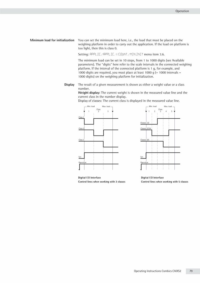
Operating Instructions Combics CAIXS2 79
Operation
Minimum load for initialization You can set the minimum load here, i.e., the load that must be placed on the weighing platform in order to carry out the application. If the load on platform is too light, then this is class 0.
Setting: Applic./Applic.1/Count./Min.init menu item 3.6.
The minimum load can be set in 10 steps, from 1 to 1000 digits (see Available parameters). The “digits" here refer to the scale intervals in the connected weighing platform. If the interval of the connected platform is 1 g, for example, and 1000 digits are required, you must place at least 1000 g (= 1000 intervals = 1000 digits) on the weighing platform for initialization.
Display The result of a given measurement is shown as either a weight value or a class number.Weight display: The current weight is shown in the measured value line and the current class in the number display.Display of classes: The current class is displayed in the measured value line.
Digital I|O Interface Digital I|O InterfaceControl lines when working with 3 classes Control lines when working with 5 classes
Class1 2 3 4 5
Min. load Max. load
Set
Classes 1/2
Classes 4/5
Operative
Classes 2/3/4
Class1 2 3
Min. load Max. load
Class 2
Set
Class 1
Class 3
Operative

80 Operating Instructions Combics CAIXS2
Operation
In the Applic./Applic.3/CLASS./Param.2/OUTP.ACT menu, menu item 4.7, you can choose the following settings for the control outputs: – off – always on – activated at stability.
The “SET” output normally changes its voltage level when the current weight exceeds the minimum load. Alternatively, you can assign the “Ready for use” function to this port. Setting: Applic./Applic.3/CLASS./PARAM.2/CTRL.SET menu item 4.3.
Example 2: There should be three classes.Configuration: The “Classification" application is selected, and printout has been set up.
O t Enter the class limits using the O key.
1 1 0 t Enter the upper limit for Class 1 using the keypad (in this example, 110 g)..
+
O t Save the upper limit for Class 1.
1 3 0 t Enter the upper limit for Class 1 using the keypad (in this example, 110 g).
O t Save the upper limit for Class 1.
t Place the sample on the weighing platform.

Operating Instructions Combics CAIXS2 81
Operation
y The result is displayed.
p t Print the results.
Note: If automatic printout of results is enabled, you do not need to press the p key. The results are printed automatically.Printout Configuration, see page 96.
Lim1 + 0.110 kg Lim2 + 0.130 kg
G# + 0.118 kg T + 0.000 kg N + 0.118 g
Class 2 -------------------

82 Operating Instructions Combics CAIXS2
Operation
Totalizing sWith this application, you can add weights to the totalizing memory. In addition to weight values, the number of separate values added to memory is also saved (APPLIC.3 menu).
Features – You can weigh up to 999 items.– Save values automatically: Simultaneous saving of net values and calculated
values (if available). Setting: Applic./APPLIC.3 /TOTALIZ menu item 3.16.
– Save weight values and calculated values from either Application 1 (for example, Counting, Weighing in Percent) or Application 2 (Checkweighing). Setting: Applic./APPLIC.3 /TOTALIZ menu item 3.22.
– Current transaction number displayed in the number display (indicating the transactions already added).
– Weighing in up to a defined target, with the totalization memory content + current weight displayed in the text lines.
– Save weight values manually or automatically.– Accurate calculation of total of weight values from two weighing platforms.– Activate Info mode with the I key .– Automatic printout when value saved.– Automatic taring of container weight.
Setting: Applic./aut.tare, menu item 3.7.
Exit Application, Delete Parameters The value of the totalizing memory remains valid until deleted by pressing the c key.You can assign different functions to the c key to delete applications. When you clear applications, you can delete either the data stored for all applications or just selected data stored for the active application. Setting: APPLIC/CLER.CF menu item 3.24.
Tare Function:If you store a tare (weight value) by pressing the ) key, you can later enter a tare value manually. The tare value you enter is added to the stored tare value. Setting: APPLIC./TARE.FNC menu item 3.25.1 (factory setting).A tare value entered manually overwrites a stored tare value (weight value). If you enter a tare value manually, a tare value (weight value) stored later overwrites the manually entered value. Setting: Applic./TARE.FNC menu item 3.25.2 .
Restore factory default settings: Applic./Reset menu item 9.1.
The Signum has a totalizing memory for totalizing individual net and gross values. You can save weight values in totalizing memory manually or automatically. Setting: Applic./APPLIC.3 /TOTALIZ menu item 3.16.
– Save value manually by pressing the O key. The value taken from the active platform is added to the value already saved in the totalization memory and the transaction counter value is increased by one. When a value is added manually, the program does not check whether the platform has been unloaded since the last time the O key was pressed.

Operating Instructions Combics CAIXS2 83
Operation
– Value saved automatically when the weighing platform is stable and the defined minimum load is exceeded. If the defined minimum load is not exceeded, you can save the item manually by pressing the O key. Regardless of these settings, the current value cannot be saved automatically unless the platform is unloaded before the next sample is placed on it. The weighing platform is considered to be unloaded when the load is less than 50% of the minimum load.
The number of items added to memory is shown in the number display. Press the c key to clear the totalizing memory. A printout is automatically generated.
With two weighing platforms connected, you can add values from both platforms to the totalizing memory. The displayed result is accurately calculated in the active weight unit.Example: When you add 1.243 g (determined on a weighing platform with three decimal places) to 1.4 g (determined on a platform with 1 decimal place), the display shows 2.643 g.
Preparation t Open the APPLIC./APPLIC.3/TOTALIZ. menu.
Available parameter settings * = Factory settingMIN.INIT Minimum load for initialization 3.6 1 digit 1 scale interval 3.6.1* 2 digit 2 scale intervals 3.6.2 5 digit 5 scale intervals 3.6.3 10 dig. 10 scale intervals 3.6.4 20 dig. 20 scale intervals 3.6.5 50 dig. 50 scale intervals 3.6.6 100 dig. 100 scale intervals 3.6.7 200 dig. 200 scale intervals 3.6.8 500 dig. 500 scale intervals 3.6.9 1000 d 1000 scale intervals 3.6.10
AUTO.SAV Autosave 3.16. OFF Off 3.16.1* ON On 3.16.2
PRT.SAV. Individual/Component printout when saved 3.17. OFF Automatic printing off 3.17.1 ON Print the entire standard print configuration every time with the O key 3.17.2*
VAL.FROM Source of data for autosave 3.22. Appl. 1 Application 1 3.22.1* Appl. 2 Application 2 3.22.2
SAV.VAL. Save value 3.23. NET Net 3.23.1* CALCUL. Calculation 3.23.2 NET+CAL Net and Calculated 3.23.3
Printout You can configure whether a printout is generated automatically when a weight value is stored in the totalizing memory or manually by pressing the p key. Setting: Applic./Applic.3/TOTALIZ menu item 3.17.– You can print manually by pressing the p key (single printout): 3.17.1. – Component log (single printout of an item): 3.17.2. The total data record is printed when you clear the totalizing memory (by pressing the c key).
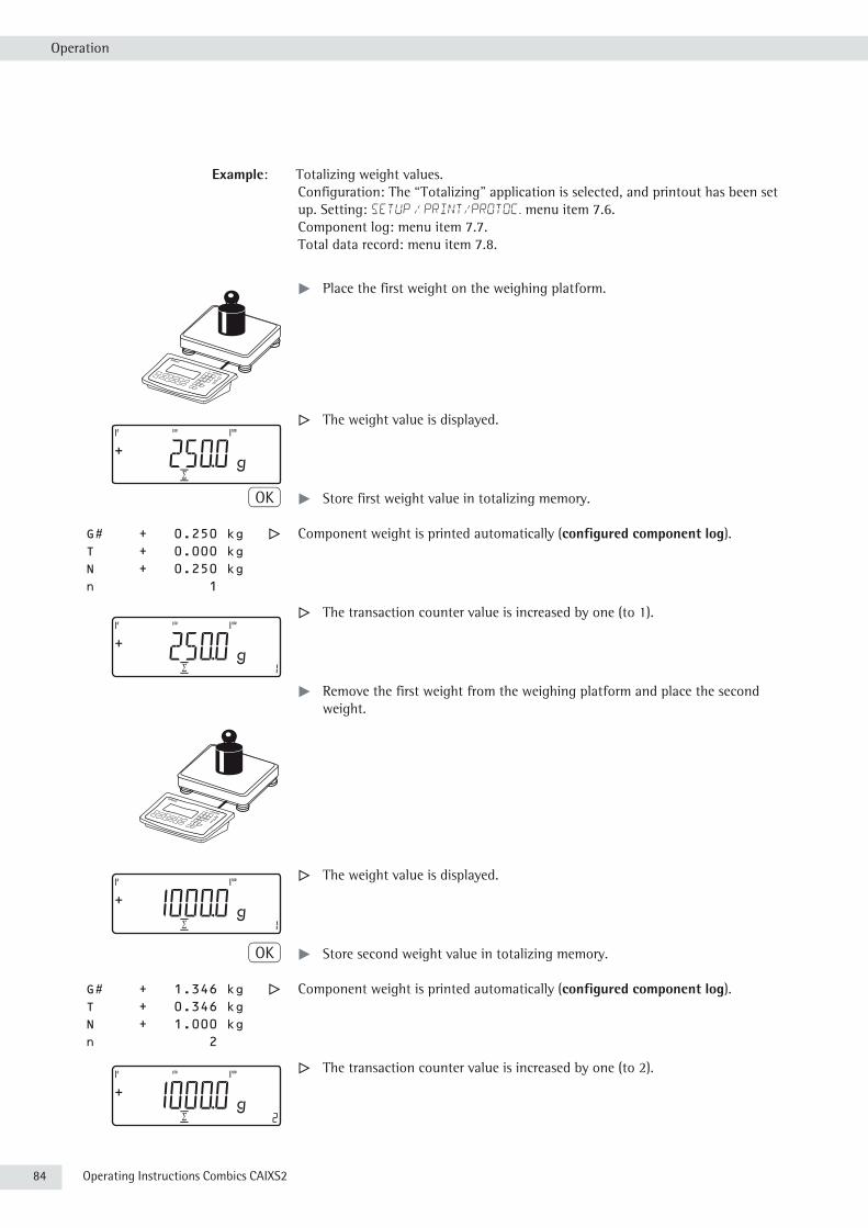
84 Operating Instructions Combics CAIXS2
Operation
Example: Totalizing weight values.Configuration: The “Totalizing" application is selected, and printout has been set up. Setting: SETUP / PRINT/PROTOC. menu item 7.6.Component log: menu item 7.7.Total data record: menu item 7.8.
t Place the first weight on the weighing platform.
y The weight value is displayed.
O t Store first weight value in totalizing memory.
G# + 0.250 kg y Component weight is printed automatically (configured component log). T + 0.000 kg N + 0.250 kg n 1
y The transaction counter value is increased by one (to 1).
t Remove the first weight from the weighing platform and place the second weight.
y The weight value is displayed.
O t Store second weight value in totalizing memory.
G# + 1.346 kg y Component weight is printed automatically (configured component log). T + 0.346 kg N + 1.000 kg n 2
y The transaction counter value is increased by one (to 2).

Operating Instructions Combics CAIXS2 85
Operation
w t Toggle the display between individual value and total.
c t End totalizing.
G# + 1.346 kg y Configured total data record is printed. T + 0.346 kg N + 1.000 kg n 2 ------------------

86 Operating Instructions Combics CAIXS2
Operation
Net Total Formulation RWith this application, you can weigh in different components up to a defined total. Each component is saved in the net-total memory (Applic.3 menu).
Features – Weigh in up to 999 components in series.– Net total formulation cannot be combined with level 1 and 2 applications
(Applic.1, Applic.2).– Current component number displayed in the number line (indicating the
component to be added).– Toggle the display from “component mode” to “additive mode” by pressing
the w key. – Component mode: Display the weight of the component currently on the
platform (for 1 second after it is saved; then the platform is tared). – Additive mode: Display the weight of all components on the platform (after
it is saved, the net weight of the last component added is displayed briefly).– Toggle to a second weighing platform while weighing in.– Activate Info mode with the I key.– Automatic component printout when it is saved.
Setting: Applic./Applic.3/NET TOT menu item 3.17.
Printout If the 3.17.2 menu item is selected, the entire component record is printed. If the 3.17.3 menu item is selected, the following items are generated only for the first component if it has been configured:Blank line, dash line, date/time, time, ID1 ... ID6, header lines 1 and 2. For subsequent components, each “component” item (“Comp xx”) is followed by a blank line.
– Automatic taring of container weight. Setting: Applic. / aut.tare menu item 3.7.
– Restore factory default settings. Setting: Applic. / Reset menu item 9.1.
Preparation t Open the APPLIC./APPLIC.3/Net.tot.menu.
Available parameter settings * = Factory settingMIN.INIT Minimum load for initialization 3.6 1 digit 1 scale interval 3.6.1* 2 digit 2 scale intervals 3.6.2 5 digit 5 scale intervals 3.6.3 10 dig. 10 scale intervals 3.6.4 20 dig. 20 scale intervals 3.6.5 50 dig. 50 scale intervals 3.6.6 100 dig. 100 scale intervals 3.6.7 200 dig. 200 scale intervals 3.6.8 500 dig. 500 scale intervals 3.6.9 1000 d 1000 scale intervals 3.6.10
PRT.SAV. Individual/Component printout when saved 3.17 OFF Automatic printing off 3.17.1 EACH.TIM. Print the entire standard print configuration every time the O key is pressed 3.17.2* ONCE Print the entire standard print configuration once with the O key 3.17.3

Operating Instructions Combics CAIXS2 87
Operation
Minimum load The minimum amount that a component must weigh before it can be saved in net-total memory. Setting: APPLIC/ APPLIC.3/NET.TOT. Menu item 3.6.
Once the limit is exceeded by the load, the value can be saved. If the load on platform is too light, the following will occur when you try to save a value:– error code Inf 29 appears– a warning signal is emitted (double-beep)– the weight value is not saved.
The minimum load required for automatic taring of the container weight on the platform (first weight) is configured under: Applic. / min.tare menu item 3.5.
The minimum load can be set in 10 steps, from 1 to 1000 digits (see Available parameters). The “digits" here refer to the scale intervals in the connected weighing platform. If the interval of the connected platform is 1 g, and 1000 digits are required, you must place at least 1000 g (= 1000 intervals) on the weighing platform for autotaring (only with the “Autotare first weight" option selected).
Net-total formulation This mode is used for weighing large and small components at the same time. It is with two weighing platforms possible to toggle from the small-component platform to the large-component
platform once during a measurement series. Once you toggle to the large-component platform, the ( and ) keys are available until a component is saved. For example, you can tare a partially-filled container taken from the small-component platform on the large component platform.
The value in component memory on the small-component platform is transferred to the large-component platform and the weight unit is converted, if necessary. The Component and Additive display modes are both available on the large-component platform.
The value read by the active platform is saved in component memory. The displayed result is accurately calculated in the active weight unit.
When you press c to stop a measurement series the tare memories for both platforms are cleared, unless the large-component platform is an SBI instrument, in which case the platform is only tared.
Example: Three components of a formula should be weighed.Configuration: The “Net-total formulation" application is selected, and printout has been set up.Setting: Applic./Applic.3/NET TOT
Component log: SETUP / PRINT/PROTOC. menu item 7.7Total data record: SETUP / PRINT/PROTOC. menu item 7.8
t Place empty container on the scale.
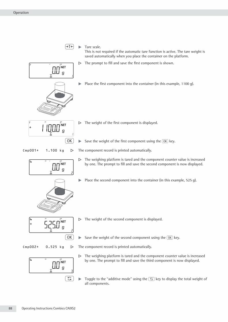
88 Operating Instructions Combics CAIXS2
Operation
) t Tare scale. This is not required if the automatic tare function is active. The tare weight is saved automatically when you place the container on the platform.
y The prompt to fill and save the first component is shown.
t Place the first component into the container (in this example, 1100 g).
y The weight of the first component is displayed.
O t Save the weight of the first component using the O key.
Cmp001+ 1.100 kg y The component record is printed automatically.
y The weighing platform is tared and the component counter value is increased by one. The prompt to fill and save the second component is now displayed.
t Place the second component into the container (in this example, 525 g).
y The weight of the second component is displayed.
O t Save the weight of the second component using the O key.
Cmp002+ 0.525 kg y The component record is printed automatically.
y The weighing platform is tared and the component counter value is increased by one. The prompt to fill and save the third component is now displayed.
w t Toggle to the “additive mode” using the w key to display the total weight of all components.

Operating Instructions Combics CAIXS2 89
Operation
y The value displayed equals the weight of components added up to now plus the current weight on the platform.
t Place the third component into the container until the desired total weight is reached (in this example, 2000 g).
y The total weight is displayed.
O t Save the weight of the third component using the O key.
Cmp003+ 0.375 kg y The component record is printed automatically.
y The component counter value is increased by one. The prompt to fill and save the fourth component is now displayed.
c t End component weighing by pressing the c key.
y Results are printed automatically (configured total data record).
n + 3 Number of components Tot.cp+ 2.000 kg Content of component memory Cont.T+ 0.296 kg Content of tare memory (container weight)
-------------------

90 Operating Instructions Combics CAIXS2
Operation
Combining Application ProgramsThe following table shows how the applications described can be combined. The basic weighing function is available at all times; it does not need to be combined with a computational function.
Select programs one after the other: Toggle using the D key.
Application 1 Application 2 Application 3 (Basic Function) (Monitoring Function) (Cumulative-value Function)Counting – TotalizingCounting Checkweighing TotalizingCounting Checkweighing –Counting Classification –Neutral measurement – TotalizingNeutral measurement Checkweighing TotalizingNeutral measurement Checkweighing –Neutral measurement Classification –Animal weighing – TotalizingAnimal weighing Checkweighing TotalizingAnimal weighing Checkweighing –Animal weighing Classification –Weighing in percent – TotalizingWeighing in percent Checkweighing TotalizingWeighing in percent Checkweighing –Weighing in percent Classification –– – Net-total formulation– Checkweighing Totalizing
Example: “Portioning" (counting z, checkweighing O with totalizing s)
Configuration:Application 1: Counting (COUNT.)Application 2: Checkweighing (CHECK.)Application 3: Totalizing (TOTALIZ): Saved value: Net + Calculated (3.23.3)
Autosave: On (3.16.2) Source of data: Application 2 (3.22.2)
Setup: Printout: PRT PROT 7.8. Printer 1: “Total: Print when FN pressed,” then select the menu line items of your choice.
t Place empty container on the scale.
) t Tare scale. This is not required if the automatic tare function is active. The tare weight is saved automatically when you place the container on the platform.
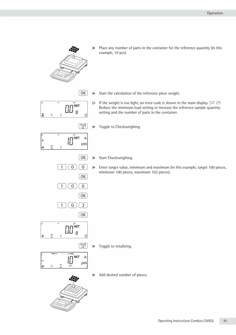
Operating Instructions Combics CAIXS2 91
Operation
t Place any number of parts in the container for the reference quantity (in this example, 10 pcs).
O t Start the calculation of the reference piece weight.
y If the weight is too light, an error code is shown in the main display Inf 29.
Reduce the minimum load setting or increase the reference sample quantity setting and the number of parts in the container.
D t Toggle to Checkweighing.
O t Start Checkweighing.
1 0 0 t Enter target value, minimum and maximum (in this example, target 100 pieces, minimum 100 pieces, maximum 102 pieces).
O
1 0 0
O
1 0 2
O
D t Toggle to totalizing.
t Add desired number of pieces.

92 Operating Instructions Combics CAIXS2
Operation
y The number of pieces is saved automatically.
tUnload the scale: Remove the samples.
t Perform further counting operations as desired.
w t Toggle display from individual value to total.
c t End the portioning options and print the final evaluation.
-------------------- Configured printout: Total. nRef + 10 pcs wRef + 0.001000 kg Setp + 100 pcs Min + 100 pcs Max + 102 pcs
n 6 *N + 0.600 kg Total + 600 pcs --------------------
Operating Instructions Combics CAIXS2 93
Operation
Configuring Printouts Purpose You can individually define each measurement printout. This should be carried out
after setting the applications since some data in the printout is application-dependent.
In the “Print parameters" menu, single, component, and total data records can be configured, which contain the available print items for the respective applications. Using the total data record for “Totalizing" and “Net-total formulation" applications, you can define which parameters are printed using the c key.
Features – Six lists each with a max. length of 30 print items – Single printout Printer 1 – Component printout Printer 1 – Total data printout Printer 1 – Single printout Printer 2 – Component printout Printer 2 – Total data printout Printer 2.– Single, component, and total data records can be configured separately.– Print single printout: p key. Auto printout of application when Setup menu is activated: – Animal weighing (averaging) – Checkweighing – Classification.– Print component printout:
Totalizing/Net-total formulation with the O key: Applic./Applic.3/TOTALIZ printout: Component printout.
– Print total data printout: For selected application Totalizing/Net-total formulation with c key.
– When switching to another application in Setup, only the application-dependent printout lists are deleted. The other printout lists remain saved.
– Print items can be deleted individually: Press and hold the ( key.– Print items “Form Feed" for record footer:
Move to the next label start for printer type: YDP14IS: “Label" and YDP04IS, setting “Label, manual form feed".
– ISO/GMP-compliant printout: The Setup menu configuration under “ISO/GMP-compliant printout” is also active for configured printouts.
Preparation t Open Menu mode (see page 35).
k k ... t Select the Setup menu.
k k ...) t Select and open the Printsubmenu.
k k ...) t Select and open the PROTOC.submenu.
Available parameter settings PROTOC. Protocol 7 HEADLIN. Header and ID header input 7.4 QTY.1 Quantity interface 1 7.5 INDIV. 1 Standard interface 1 7.6 COMPON.1 Component interface 1 7.7 TOTAL 1 Result interface 1 7.8 QTY.2 Quantity interface 2 7.9 INDIV. 2 Standard interface 2 7.10 COMPON.2 Component interface 7.11
94 Operating Instructions Combics CAIXS2
Operation
TOTAL 2 Result interface 2 7.12 gmp.prot ISO/GMP 7.13 DAT/TIM Date without time 7.14 AUT.ONCE Automatic printout after stability 7.15 FLEX. PRN Flex print 7.16 DEC.SEP. Decimal separator 7.17 ALIB.MEM Alibi memory 7.18
RESET Restore factory default settings 9 Setting the factory settings 9.1
– The rows of the printout list can be called up and activated individually. Example: see under Configuration, menu item 7.6.
– The print selection set as active appears with the left selection bar on the display, e.g. gross, tare, net.
t Expand the printout: Press the ) key. The selection bar appears on the right of the display.
t Select print items: Press the k key.t Save the desired print items: Press the ) key.t Press the ( key to change the print selection set as active. The selection bar
appears on the left. The required print item is set as active and appears in the printout.
– Print items can be deleted individually from the active printout selection: Press and hold the ( key.
t Save settings with the ) key and exit Setup: Press the ( key several times.
Additional functions Printing the “Selection" and “List" SettingsLIST: Output of the current printout listSELECT: Print currently selectable items
t When the selection bar is in LIST or SELECT: Press the p key.
Printout (example) Indiv.Prt List====================Net (N)Gross (G#)TareTare (T2/PT2)Piece count====================etc.
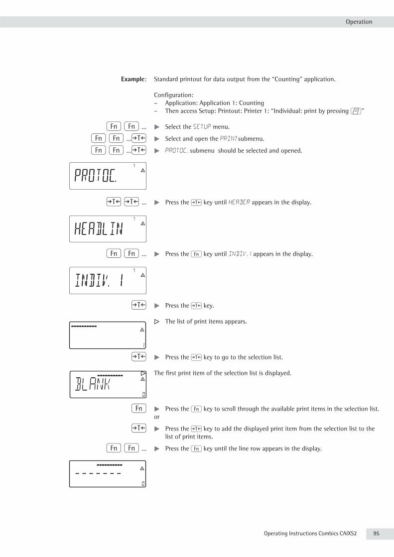
Operating Instructions Combics CAIXS2 95
Operation
Example: Standard printout for data output from the “Counting" application.
Configuration:– Application: Application 1: Counting– Then access Setup: Printout: Printer 1: “Individual: print by pressing p"
k k ... t Select the Setup menu.
k k ...) t Select and open the Printsubmenu.
k k ...) t PROTOC. submenu should be selected and opened.
) ) ... t Press the ) key until header appears in the display.
k k ... t Press the k key until indiv.1 appears in the display.
) t Press the ) key.
y The list of print items appears.
) t Press the ) key to go to the selection list.
y The first print item of the selection list is displayed.
k t Press the k key to scroll through the available print items in the selection list.or
) t Press the ) key to add the displayed print item from the selection list to the list of print items.
k k ... t Press the k key until the line row appears in the display.
blank

96 Operating Instructions Combics CAIXS2
Operation
) t Press the ) key to save the selection.
y The counter value is increased by one.
k k ... t Press the k key until the “reference weight" entry is displayed.
) t Press the ) key to save the selection.
t You can now select additional print items in the same way.
( ( ... t To exit print item entry, press the ( key until APPLIC. appears in the display. y
) t Press and hold the ) key (2–3 sec) to switch to weighing mode.
t Carry out weighing.
p t Press the p key to print the results.
-------------------- Printout example nRef + 5 pcs wRef + 8 pcs wRef + 0.4000 g

Operating Instructions Combics CAIXS2 97
Operation
Product Data Memory Purpose The product data memory stores initialization data and user data (product and tare
values).
Features – The product data memory has 100 memory cells for product or tare values. This means that e.g. 80 application memories and 20 tare memories are available.
– Each memory cell is uniquely identified by a number up to three digits.– The product data memory can be used with the following applications:
Application 1 Application 2 – Weighing – Checkweighing – Counting – Classification – Neutral measurement – Animal weighing – Weighing in percent
– Data records can be created, overwritten, and individually deleted.– Data remains stored when the scale is switched off.
Saving Product Data (in this example in the “Counting" application)t Start the Counting application. t Enter a memory number and press and hold the R key (min 2 seconds).
Saving Preset Tare Valuest Allocate preset tare memory. t Enter a memory number and press and hold the t key (min 2 seconds).
Activating Saved Product or Tare Valuest Enter a memory number and press the R key.
Displaying Information for a Specific Product or Tare ValueT Enter a memory number and press the I key. – Use the k key to switch between wRef (average piece weight) and nRef
(quantity). – Use the ) key to scroll the displayed value to the right. – Use the R key to activate the displayed memory. – Use the c key (min. 2 seconds) to delete the displayed memory. t Exit the mode using the c key.
Displaying Information for all Product or Tare Memoriest Press the R key to display the first memory number.– Press the k key to scroll through in lexical order (e.g. 1, 3, 333, 4, etc.).– Use the R key to activate the selected memory number. – Press the I key to display the saved product values. – Press and hold the c key (min. 2 seconds) to delete the selected memory
number. t Exit the mode using the c key.
Deleting Specific Memory Numbers t Enter a memory number and press and hold the c key.

98 Operating Instructions Combics CAIXS2
Operation
Example: Using the Counting application with a stored average piece weight. Configuration: Application: Counting (COUNT.)
Saving the Average Piece Weightt Start the application. t Determine the average piece weight using one of the methods described above. t Enter the memory cell number using the keypad, and press and hold the R
key (min 2 seconds).
Loading the Average Piece Weight or Reference Sample Quantityt Enter the memory cell number and press the I key. – Use the k key to switch between wRef (average piece weight) and nRef
(quantity). – Use the ) key to scroll the displayed value to the right. – Use the R key to activate the displayed memory. – Use the c key (min. 2 seconds) to delete the displayed memory. t Exit the mode using the c key.
Overwriting Data in a Memory Cellt Enter the memory cell number to be overwritten via the keypad.t Press and hold the R key (min 2 seconds). y The previous average piece weight is overwritten.
t To cancel without saving, press the c key.
Deleting an Average Piece Weightt Enter the memory cell number of the average piece weight to be overwritten.t Press the I key. t Delete the displayed value by pressing and holding the c key (min. 2 seconds).

Operating Instructions Combics CAIXS2 99
Data interface
Data InterfacesThe indicator is equipped with the following data interfaces:– COM1: –Standard data interface (RS-232 (A21), 485 (A22), 422 (A23).
The interface can be configured in the Setup menu for different input and output functions (e.g. printer, 2nd weighing platform, PC).
3 Warning when using third-party RS-232 connecting cables: the pin assignments
may not be compatible with Sartorius equipment.
Specifications Serial interface: Interface operation: Full duplex
Level: COM1: RS-232 or RS-422Connection to device: Weighing platforms Connection via screw terminals in the housing,
cable routed into the housing via a cable gland. Transmission rate: 150, 300, 600, 1200, 2400, 4800, 9600, 19200
baud (depending on the operating mode) Number of data bits: 7, 8 bits Parity: Space, odd, even, none (depending on the
operating mode) Number of stop bits: 1 or 2 Handshake mode: Software (XON/XOFF), hardware (1 character after
CTS)Protocols: SBI, XBPI-232, XBPI-485, SMA
Network address 4): 0, 1, 2, ..., 31 SBI: Manual data output: Without stability, after stability, configurable
printout SBI: Auto data output: Without stability, at stability, at user-defined
intervalsSBI: Output format: 16 or 22 characters Printout of application data: Configurable printout

100 Operating Instructions Combics CAIXS2
Data interfaces
Configuring the Data Interface as a COM Port (datprot)You can configure the interface as a COM port in either COM1 or UniCOM, “Data Protocol" (datprot) menu item.
SBI communication This is a simple ASCII interface.Data output is configured under menu items 6.1 and 6.3: – Manual output of displayed value with or without stability (menu items 6.1.1
and 6.1.2).– Automatic output of displayed value with or without stability (menu items
6.1.4 and 6.1.5) at intervals defined by display updates. The number of display intervals is set in menu item 6.3.
– Output of a configurable printout (menu item 6.1.7). Output is linked to the “Printouts” menu item (datprot), (see page 96 “Configuring Printouts").
If you do not activate and configure a user-definable data record, the printout simply contains the current value displayed on the display and control unit (weight with unit, calculated value, alphanumeric display).
SMA communication Standardized communications protocol of the Scale Manufacturers Association.
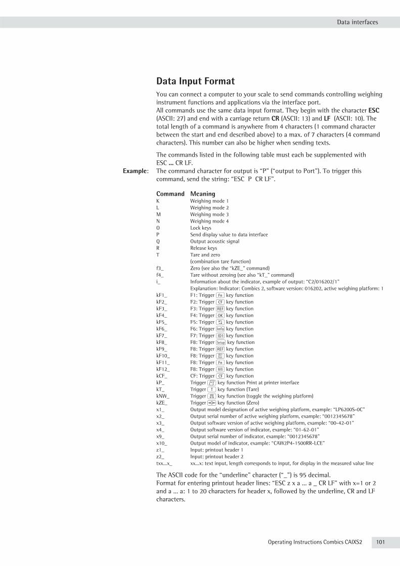
Operating Instructions Combics CAIXS2 101
Data interfaces
Data Input FormatYou can connect a computer to your scale to send commands controlling weighing instrument functions and applications via the interface port.All commands use the same data input format. They begin with the character ESC (ASCII: 27) and end with a carriage return CR (ASCII: 13) and LF (ASCII: 10). The total length of a command is anywhere from 4 characters (1 command character between the start and end described above) to a max. of 7 characters (4 command characters). This number can also be higher when sending texts.
The commands listed in the following table must each be supplemented with ESC ... CR LF.
Example: The command character for output is “P” (“output to Port”). To trigger this command, send the string: “ESC P CR LF”.
Command MeaningK Weighing mode 1L Weighing mode 2M Weighing mode 3N Weighing mode 4O Lock keysP Send display value to data interfaceQ Output acoustic signalR Release keysT Tare and zero (combination tare function)f3_ Zero (see also the “kZE_" command)f4_ Tare without zeroing (see also “kT_" command)i_ Information about the indicator, example of output: “C2/016202/1" Explanation: Indicator: Combics 2, software version: 016202, active weighing platform: 1kF1_ F1: Trigger k key functionkF2_ F2: Trigger c key functionkF3_ F3: Trigger r key functionkF4_ F4: Trigger O key functionkF5_ F5: Trigger w key functionkF6_ F6: Trigger I key functionkF7_ F7: Trigger g key functionkF8_ F8: Trigger H key functionkF9_ F8: Trigger r key functionkF10_ F8: Trigger J key functionkF11_ F8: Trigger k key functionkF12_ F8: Trigger L key functionkCF_ CF: Trigger c key functionkP_ Trigger p key function Print at printer interfacekT_ Trigger T key function (Tare)kNW_ Trigger n key function (toggle the weighing platform)kZE_ Trigger ( key function (Zero)x1_ Output model designation of active weighing platform, example: “LP6200S-0C"x2_ Output serial number of active weighing platform, example: “0012345678"x3_ Output software version of active weighing platform, example: “00-42-01"x4_ Output software version of indicator, example: “01-62-01"x9_ Output serial number of indicator, example: “0012345678"x10_ Output model of indicator, example: “CAW2P4-1500RR-LCE"z1_ Input: printout header 1z2_ Input: printout header 2txx...x_ xx...x: text input, length corresponds to input, for display in the measured value line
The ASCII code for the “underline” character (“_”) is 95 decimal.Format for entering printout header lines: “ESC z x a ... a _ CR LF" with x=1 or 2 and a ... a: 1 to 20 characters for header x, followed by the underline, CR and LF characters.
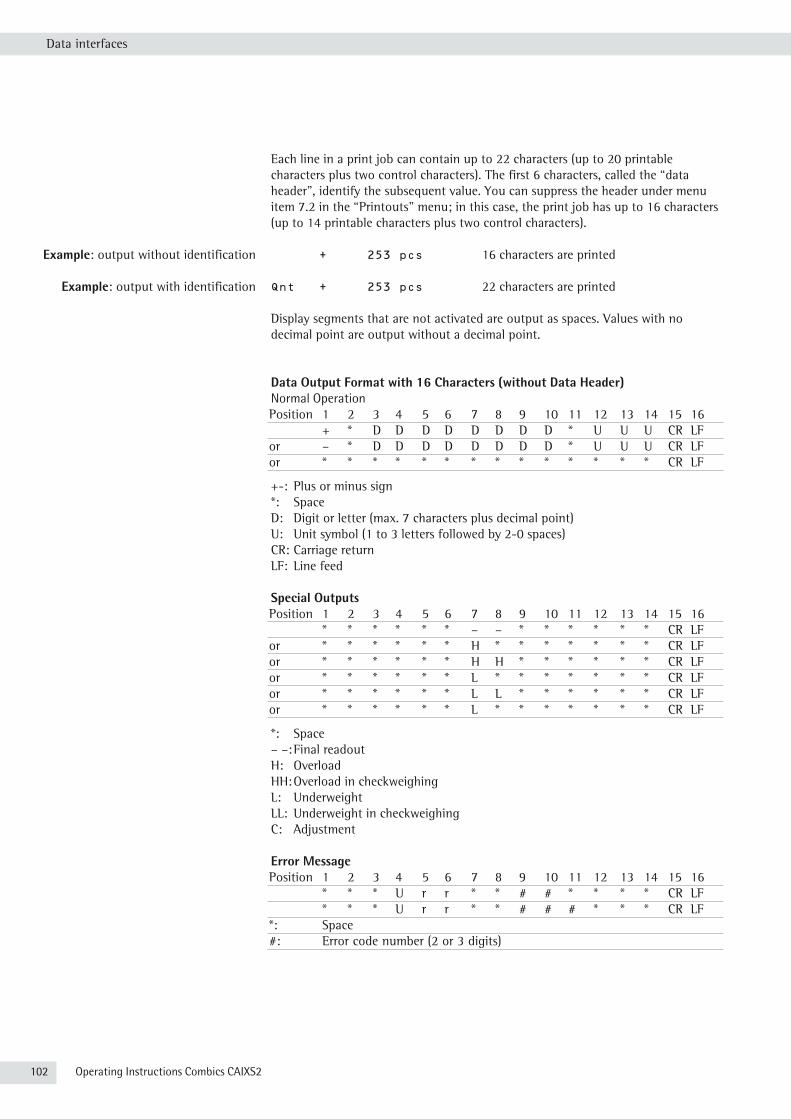
102 Operating Instructions Combics CAIXS2
Data interfaces
Each line in a print job can contain up to 22 characters (up to 20 printable characters plus two control characters). The first 6 characters, called the “data header”, identify the subsequent value. You can suppress the header under menu item 7.2 in the “Printouts” menu; in this case, the print job has up to 16 characters (up to 14 printable characters plus two control characters).
Example: output without identification + 253 pcs 16 characters are printed
Example: output with identification Qnt + 253 pcs 22 characters are printed
Display segments that are not activated are output as spaces. Values with no decimal point are output without a decimal point.
Data Output Format with 16 Characters (without Data Header)Normal OperationPosition 1 2 3 4 5 6 7 8 9 10 11 12 13 14 15 16 + * D D D D D D D D * U U U CR LFor – * D D D D D D D D * U U U CR LFor * * * * * * * * * * * * * * CR LF
+-: Plus or minus sign *: Space D: Digit or letter (max. 7 characters plus decimal point)U: Unit symbol (1 to 3 letters followed by 2-0 spaces)CR: Carriage returnLF: Line feed
Special OutputsPosition 1 2 3 4 5 6 7 8 9 10 11 12 13 14 15 16 * * * * * * – – * * * * * * CR LFor * * * * * * H * * * * * * * CR LFor * * * * * * H H * * * * * * CR LFor * * * * * * L * * * * * * * CR LFor * * * * * * L L * * * * * * CR LFor * * * * * * L * * * * * * * CR LF
*: Space– –: Final readoutH: OverloadHH: Overload in checkweighingL: UnderweightLL: Underweight in checkweighingC: Adjustment
Error MessagePosition 1 2 3 4 5 6 7 8 9 10 11 12 13 14 15 16 * * * U r r * * # # * * * * CR LF * * * U r r * * # # # * * * CR LF*: Space#: Error code number (2 or 3 digits)

Operating Instructions Combics CAIXS2 103
Data interfaces
Example: Output weight value of +1255.7 g
Position 1 2 3 4 5 6 7 8 9 10 11 12 13 14 15 16 + * * * 1 2 5 5 . 7 * g * * CR LF
Position 1: Plus +, or minus - or spacePosition 2: SpacePositions 3-10: Weight value with decimal point. leading zeros are output as
spaces.Position 11: SpacePositions 12-14: Characters for unit of measure, space, or ! sign as a symbolPosition 15: Carriage returnPosition 16: Line feed
Data Output Format with 22 CharactersNormal Operation
1 2 3 4 5 6 7 8 9 10 11 12 13 14 15 16 17 18 19 20 21 22I I I I I I + D D D D D D D D D * U U U CR LFI I I I I I - D D D D D D D D D * U U U CR LF* * * * * * * * * * * * * * * * * * * * CR LF
I: ID code character, right-justified with spaces+-: Plus or minus sign*: SpaceD: Digit or letter (max. 7 characters plus decimal point) U: Unit symbol (1 to 3 letters followed by 2-0 spaces)CR: Carriage returnLF: Line feed
Special Outputs
1 2 3 4 5 6 7 8 9 10 11 12 13 14 15 16 17 18 19 20 21 22S t a t * * * * * * * * - - * * * * * * CR LFS t a t * * * * * * * * H * * * * * * * CR LFS t a t * * * * * * * * H H * * * * * * CR LFS t a t * * * * * * * * L * * * * * * * CR LFS t a t * * * * * * * * L L * * * * * * CR LFS t a t * * * * * * * * C * * * * * * * CR LF
*: Space– –: Final readoutH: OverloadHH: Overload in checkweighingL: UnderweightLL: Underweight in checkweighingC: Adjustment
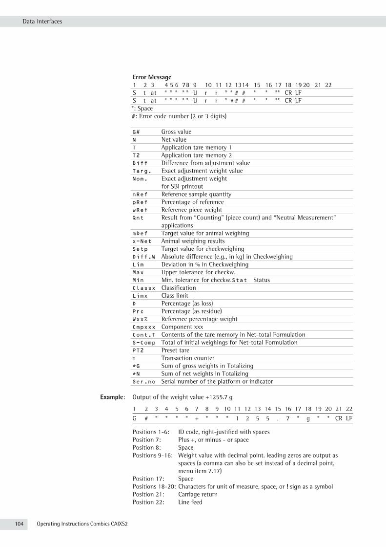
104 Operating Instructions Combics CAIXS2
Data interfaces
Error Message1 2 3 4 5 6 7 8 9 10 11 12 13 14 15 16 17 18 19 20 21 22S t a t * * * * * U r r * * # # * * * * CR LFS t a t * * * * * U r r * # # # * * * * CR LF*: Space#: Error code number (2 or 3 digits)
G# Gross valueN Net valueT Application tare memory 1T2 Application tare memory 2Diff Difference from adjustment valueTarg. Exact adjustment weight valueNom. Exact adjustment weight
for SBI printoutnRef Reference sample quantitypRef Percentage of referencewRef Reference piece weightQnt Result from “Counting" (piece count) and “Neutral Measurement"
applicationsmDef Target value for animal weighingx-Net Animal weighing resultsSetp Target value for checkweighingDiff.W Absolute difference (e.g., in kg) in CheckweighingLim Deviation in % in CheckweighingMax Upper tolerance for checkw.Min Min. tolerance for checkw.Stat StatusClassx ClassificationLimx Class limitD Percentage (as loss)Prc Percentage (as residue)Wxx% Reference percentage weightCmpxxx Component xxxCont.T Contents of the tare memory in Net-total FormulationS-Comp Total of initial weighings for Net-total FormulationPT2 Preset tare n Transaction counter *G Sum of gross weights in Totalizing *N Sum of net weights in Totalizing Ser.no Serial number of the platform or indicator
Example: Output of the weight value +1255.7 g
1 2 3 4 5 6 7 8 9 10 11 12 13 14 15 16 17 18 19 20 21 22
G # * * * * + * * * 1 2 5 5 . 7 * g * * CR LF
Positions 1-6: ID code, right-justified with spacesPosition 7: Plus +, or minus - or spacePosition 8: SpacePositions 9-16: Weight value with decimal point. leading zeros are output as
spaces (a comma can also be set instead of a decimal point, menu item 7.17)
Position 17: SpacePositions 18-20: Characters for unit of measure, space, or ! sign as a symbolPosition 21: Carriage returnPosition 22: Line feed

Operating Instructions Combics CAIXS2 105
Data interfaces
h If the weight value is output with 10-fold increased resolution, this value is not
permitted to be printed or saved in a weighing instrument operated in legal metrology in the SBI mode. In this case, the unit symbol is not included with output.
External Keyboard Functions (PC Keyboard)Setting: Setup /BARCODE / EXT.KEYB. The alphanumeric key codes implemented here are specific to the German keyboard layout. The following alphanumeric characters are used (some require the “Shift” key):a–z, A–Z, 0–9, <space>, and these characters: ,.\+’<>/»$@%/();=:_?*
Function keys:PC keyboard Combics 2F1 key )F2 key (F3 key nF4 key cF5 key rF6 key OF7 key DF8 key IF9 key IF10 key IF11 key dF12 key kPrint key pReturn key OPos 1 key cBackspace key cESC key c
Configuring the Data Interface as a Printer Port (printer)You can connect one or two strip printers or one or two label printers to the Combics. Configure the COM1 and UniCOM interfaces as printer ports in the Printer menu item.
There are several actions that generate the command for outputting data to the printer port: – Pressing the p key. If the operating menu is active, all menu settings under
the active menu level are printed. – Upon receipt of the “Esc k P _" SBI command.
For details, see the section entitled “Data Input Format” in this chapter.– In some applications, pressing a given key (e.g., to save a value or start a
routine) also generates a print command. In this case, a configurable printout is generated with application-specific data.
The P and l symbols are displayed when data is being output to the printer port.

106 Operating Instructions Combics CAIXS2
Data interfaces
Configuring a PrintoutPrintouts are configured in the Setup menu under “Printouts" (setup / print /
protoc.). This should be carried out after configuring the application since some data in the printout is application-dependent.You can configure a separate printout for each interface. Each printout is comprised of different information blocks that can be activated or deactivated via multiple selection in the menu.For the “Totalizing" and “Net-total Formulation" applications, the totalizing/results printout can be configured independent of the individual/component printout.
Headers2 headers each with a max. of 20 characters are available (e.g., for printing the company name). Input: menu items 7.4.1 and 7.4.2. Empty headers are not printed.
Example Print image:
EISENSCHMIDT GOETTINGEN
In this example, the company name is printed centered because there are 4 and 5 spaces before the text.
GMP-Compliant PrintoutsWhen this function, the printout is supplemented with a GMP header and a GMP footer (GMP: “Good Manufacturing Practice”). Setting: menu item 7.13.
The GMP header precedes the first measured result. The GMP footer is printed either after each individual measurement result ("GMP-compliant printout always for 1 result", 7.13.2) or after the last result in a series of measurements ("GMP-compliant printout always for several application results,” menu item 7.13.3). To end a series of measured results, press and hold the p key. In this case, the p symbol is displayed after the GMP header is printed and remains in the display until the GMP footer is printed.
If you toggle to a different platform while a GMP printout of several measured results is being generated (7.13.3), the GMP footer for the platform used up to that point is generated when you press the n key. The GMP header for the other platform is included on the next printout generated.A GMP-compliant printout is generated automatically at the conclusion of calibration/adjustment, linearization routines, as well as when you set or clear a preload.
When printing GMP-compliant printouts on label printers under menu setting 7.13.3, the relationship between the GMP header and footer is lost (printed on different labels). GMP-compliant printouts on label printers, therefore, should only take place using menu setting 7.13.2. Three examples of GMP headers and one example of a footer are shown in the following.

Operating Instructions Combics CAIXS2 107
Data interfaces
Weighing platform WP 1:-------------------- Dash line14.01.2013 09:43 Date/time Type CAIXS2 Combics TypeSer.no. 12345678 Combics serial no.Vers. C2 100.280810 Software version ApplicationBVers. 01-62-03 Software version Basic software-------------------- Dash line
Weighing platform WP 2 (xBPI printout): -------------------- Dash line14.01.2013 9:45 AM Date/timeType CAIXS2 Combics Type Ser.no. 12345678 Combics serial no.Vers. C2 100.280810 Software version ApplicationBVers. 01-62-03 Software version Basic softwareType IS12000S Platform typeSer.No 12345678 Platform serial no.-------------------- Dash line
Weighing platform WP 2 (SBI printout): -------------------- Dash line14.01.2013 9:45 AM Date/timeType CAIXS2 Combics TypeSer.no. 12345678 Combics serial no.Vers. C2 100.280810 Software version ApplicationBVers. 01-62-03 Software version of basic version
Type SBI (Platform type)-------------------- Dash line
GMP footer:-------------------- Dash line14.01.2013 9:45 AM Date/time Name: Field for signature Blank line-------------------- Dash line
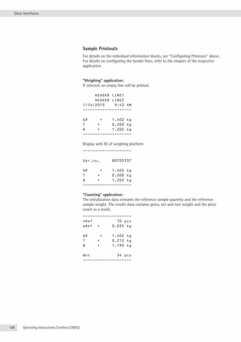
108 Operating Instructions Combics CAIXS2
Data interfaces
Sample PrintoutsFor details on the individual information blocks, see “Configuring Printouts" above. For details on configuring the header lines, refer to the chapter of the respective application.
“Weighing” application:If selected, an empty line will be printed.
HEADER LINE1 HEADER LINE2 1/14/2013 9:43 AM--------------------
G# + 1.402 kgT + 0.200 kgN + 1.202 kg--------------------
Display with ID of weighing platform
--------------------
Ser.no. 80705337
G# + 1.402 kgT + 0.200 kgN + 1.202 kg--------------------
“Counting” application:The initialization data contains the reference sample quantity and the reference sample weight. The results data contains gross, net and tare weight and the piece count as a result.
--------------------nRef 10 pcswRef + 0.035 kg
G# + 1.402 kgT + 0.212 kgN + 1.190 kg
Qnt 34 pcs--------------------
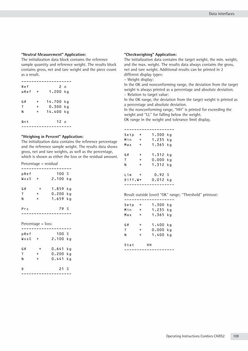
Operating Instructions Combics CAIXS2 109
Data interfaces
“Neutral Measurement” Application:The initialization data block contains the reference sample quantity and reference weight. The results block contains gross, net and tare weight and the piece count as a result.
--------------------Ref 2 owRef + 1.200 kg
G# + 14.700 kgT + 0.300 kgN + 14.400 kg
Qnt 12 o--------------------
“Weighing in Percent” Application:The initialization data contains the reference percentage and the reference sample weight. The results data shows gross, net and tare weights, as well as the percentage, which is shown as either the loss or the residual amount.
Percentage = residual --------------------pRef 100 %Wxx% + 2.100 kg
G# + 1.859 kgT + 0.200 kgN + 1.659 kg
Prc 79 %--------------------
Percentage = loss: --------------------pRef 100 %Wxx% + 2.100 kg
G# + 0.641 kgT + 0.200 kgN + 0.441 kg
D 21 %--------------------
“Checkweighing” Application:The initialization data contains the target weight, the min. weight, and the max. weight. The results data always contains the gross, net and tare weight. Additional results can be printed in 2 different display types: – Weight display: In the OK and nonconforming range, the deviation from the target weight is always printed as a percentage and absolute deviation.– Relation to target value: In the OK range, the deviation from the target weight is printed as a percentage and absolute deviation. In the nonconforming range, “HH" is printed for exceeding the weight and “LL" for falling below the weight.OK range in the weight and tolerance limit display.
--------------------Setp + 1.300 kgMin + 1.235 kgMax + 1.365 kg
G# + 1.312 kgT + 0.000 kgN + 1.312 kg
Lim + 0.92 %Diff.W+ 0.012 kg--------------------
Result outside (over) “OK” range; “Threshold” printout: --------------------Setp + 1.300 kgMin + 1.235 kgMax + 1.365 kg
G# + 1.400 kgT + 0.000 kgN + 1.400 kg
Stat HH--------------------
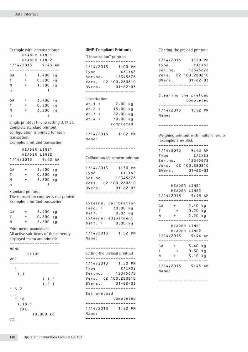
110 Operating Instructions Combics CAIXS2
Data interface
Example with 2 transactions: HEADER LINE1 HEADER LINE21/14/2013 9:43 AM--------------------G# + 1.400 kgT + 0.200 kgN + 1.200 kgn 1
G# + 3.400 kgT + 0.200 kgN + 3.200 kgn 2
Single printout (menu setting 3.17.2).Complete standard printout configuration is printed for each transaction. Example: print 2nd transaction
HEADER LINE1 HEADER LINE21/14/2013 9:43 AM--------------------G# + 2.400 kgT + 0.200 kgN + 2.200 kgn 2
Standard printout The transaction counter is not printed.Example: print 2nd transaction
G# + 2.400 kgT + 0.200 kgN + 2.200 kg
Print menu parameters:All active sub-items of the currently displayed menu are printed:--------------------MENU SETUPWP1-------------------- 1 1.1 1.1.2 1.2.11.3.2... 1.18 1.18.1 CAL. 10.000 kgetc.
GMP-Compliant Printouts
"Linearization" printout--------------------1/14/2013 1:00 PMType CAIXS2Ser.no. 12345678Vers. C2 100.280810BVers. 01-62-03--------------------
LinearizationWt.1 + 7.00 kgWt.2 + 15.00 kgWt.3 + 22.00 kgWt.4 + 30.00 kg completed--------------------1/14/2013 1:02 PMName:
--------------------
Calibration/adjustment printout--------------------1/14/2013 1:50 PMType CAIXS2Ser.no. 12345678Vers. C2 100.280810BVers. 01-62-03--------------------
External calibrationTarg. + 30.00 kgDiff. - 0.03 kgExternal adjustmentDiff. + 0.00 kg--------------------1/14/2013 1:52 PMName:
--------------------Setting the preload printout--------------------1/14/2013 1:50 PMType CAIXS2Ser.no. 12345678Vers. C2 100.280810BVers. 01-62-03--------------------Set preload completed--------------------1/14/2013 1:52 PMName:--------------------
Clearing the preload printout--------------------1/14/2013 1:50 PMType CAIXS2Ser.no. 12345678Vers. C2 100.280810BVers. 01-62-03--------------------
Clearing the preload completed--------------------1/14/2013 1:52 PMName:
--------------------
Weighing printout with multiple results (Example: 2 results):--------------------1/14/2013 9:43 AMType CAIXS2Ser.no. 12345678Vers. C2 100.280810BVers. 01-62-03--------------------
HEADER LINE1 HEADER LINE21/14/2013 9:43 AM--------------------G# + 2.40 kgT + 0.20 kgN + 2.20 kg-------------------- HEADER LINE1 HEADER LINE21/14/2013 9:44 AM--------------------G# + 3.40 kgT + 0.30 kgN + 3.10 kg--------------------1/14/2013 9:45 AMName:
--------------------

Operating Instructions Combics CAIXS2 111
Error Codes
Error CodesErrors are divided into the following:– Dynamic errors are displayed for the duration of the error with an error code (e.g. inf 01).– Temporary errors are displayed for 2 seconds (e.g. inf 07).– Fatal errors are displayed continuously (e.g. err101; a reset is required to clear these).
Display Cause RemedyNo display segments
No power present Check power supply
------- Key has no function in this status
Flashing k Battery defective or time changed Set time
H Weighing range exceeded Unload the balance
l or Err 54 Weighing pan is not in place Position the weighing pan
ERR 101–104 Key is stuck Key pressed when switching on
Release key or contact your local Sartorius Service Center
Err 320 Operating program memory faulty Contact your local Sartorius Service Center
Err 335 Verified weighing platform not compatible with the connected terminal
Connect a compatible weighing platform
Err 340 New EEPROM loaded (Service) Turn the scale off and then on again. If the error code Err340 is still displayed, please contact your local Sartorius Service Center
Err 341 RAM has lost data; battery is dead Leave the scale connected to power for at least 10 hours
Err 343 Loss of data in the memory area for transaction numbers in external alibi memory
Contact your local Sartorius Service Center
Inf 01 Data output not compatible with output format Set output format correctly
inf 02 Adjustment condition was not maintained e.g., not tared or weighing pan loaded
Calibrate only when zero is displayed Unload the scale, press ) key to tare
inf 03 Adjustment could not be completed within a certain time.
Allow to warm up again and repeat the adjustment process
Inf 06 Built-in adjustment weight defective Contact your local Sartorius Service Center
inf 07 Function not allowed in scales verified for use in legal metrology
Contact your local Sartorius Service Center
inf 08 The load on the scale is too heavy to zero the readout Check whether “Tare/zero at power on” (1.12) is set
Inf 09 Taring is not possible when the scale gross weight is zero Zero the scale
inf 10 Tare key is blocked when there is data in the tare memory The application program data must be deleted before taring
inf 18 Preload is too light
Inf 19 Preload is too heavy
inf 29 Minimum load not reached Reduce min. load (under Application, menu item 3.6)
Inf 30 BPI ID (BPI byte) not deleted in current weighing platform (COM1 is fixed on XBPI data communication)
Reset weighing parameters to factory settings for current weighing platform
Inf 31 Interface handshake activated (XOFF, CTS) Send XON, unblock CTS
inf 71 Cannot store the current weight value (e.g., control limits too low or too high)
None
inf 72 Cannot store the current weight value (e.g., the transaction counter has reached its limit)
None
inf 73 Data cannot be written or read Contact your local Sartorius Service Center
inf 74 Function is blocked (e.g., menu is locked, device is already configured to another interface)
None
NO WP No weighing platform connected Connect weighing platform

112 Operating Instructions Combics CAIXS2
Care and Maintenance
Care and Maintenance
ServiceRegular servicing by a Sartorius technician will extend the service life of your equipment and ensure its continued weighing accuracy. Sartorius offers its customers service contracts with regular maintenance intervals ranging from one month to two years. The frequency of the maintenance intervals depends on the operating conditions and the operator's tolerance requirements.
Repairs
3 Disconnect the power supply to the defective equipment immediately (unplug the
power cord from the mains supply). Repair work must be performed by authorized Sartorius service technicians using original spare parts. Repairs performed by untrained persons may result in considerable hazards for the user.
3 If a cable or cable gland is damaged or defective, replace the cable as a complete unit with all its connectors.
3 Do not open the indicator while it is carrying current. Wait at least 10 seconds after disconnecting it from power before beginning to open the equipment. Proper fitting of all surfaces is essential for the IP rating of the housing; for this reason the device must be opened and closed by a certified technician.
CleaningIndicators are designed in compliance with European Hygienic Equipment Design Group (EHEDG) directives on suitable measures to avoid contamination, so that they are particularly easy to clean and disinfect.
3
Disconnect the power supply to the indicator (unplug the power cord from the mains supply). If necessary, disconnect the data cable.
3 Make sure that no liquid enters the indicator.
3 Do not use aggressive cleaning agents (solvents or similar agents).
3
Do not spray the device with water or blow with compressed air.
t Clean the indicator with a cloth lightly moistened with a soap solution. For use in the food industry, use a cleaning agent suitable for that particular working environment.
t Wipe the indicator with a soft, dry cloth.

Operating Instructions Combics CAIXS2 113
Care and Maintenance
Cleaning the Stainless Steel Surfaces– Only use conventional household cleaning agents that are suitable for stainless
steel. – Only use solvents for cleaning stainless steel parts.
t All stainless steel parts should be cleaned at regular intervals: Rub stainless steel surfaces with a moist cloth, with a cleaning agent if required, then remove all residue from the surface.
t Allow device to dry. For additional protection, protective oil may be applied.
Replacing the Dust CoverDamaged dust covers should be replaced immediately.
t Remove damaged dust cover.t Place the new dust cover on the indicator and press it over the edge of the
front and rear side of the device until it is fixed in place.
Safety InspectionsSafe operation of the device is no longer ensured when:
– there is visible damage to the device or power cord– the integrated power supply for the indicator no longer functions properly– the device has been stored for a relatively long period under unfavorable
conditions (e.g. excessive humidity)
If there is any indication that safe operation of the device is no longer warranted:t Disconnect the power supply to the device (unplug the power cord from the
mains supply) and make sure the device cannot be used for the time being.t Notify your nearest Sartorius Service Center.
Maintenance and repair work may only be carried out by service technicians: – who have access to the required maintenance manuals and– who have attended the appropriate training workshops.
h The seals on the device indicate that the device may only be opened and
maintained by authorized specialist personnel, so that the correct and safe operation of the device is ensured and the guarantee remains valid.

114 Operating Instructions Combics CAIXS2
Disposal
Disposal
If the packaging is no longer needed, it can be disposed of by local waste disposal authorities. The packaging is made of environmentally friendly materials that can be used as secondary raw materials. If you no longer require the packaging, you can dispose of it free of charge in Germany through the Vfw dual system (contract number D-59101-2009-1129). In Germany, you can dispose of this material using the VfW dual system (contract number D-59101-2009-1129).
The equipment, including accessories and batteries, should not be disposed of as regular household waste. EU legislation requires its Member States to collect electrical and electronic equipment and dispose of it separately from other unsorted municipal waste so that it may be recycled.
In Germany and several other countries, Sartorius itself assumes responsibility for the return and conformant disposal of its electronic and electrical products. Such equipment may not be thrown out with household waste or brought to collection centers run by local public disposal operations – not even by small commercial operators. For disposal in Germany and in the other member nations of the European Economic Area (EEA), please contact our local service technicians or our Service Center in Goettingen, Germany:
Sartorius Industrial Scales GmbH & Co. KG Leinetal 2 37120 Bovenden, Germany
SWT GÖ: WEEE reg. no. DE 49923090
In countries that are not members of the European Economic Area (EEA) or where no Sartorius subsidiaries or dealerships are located, please contact your local authorities or a commercial disposal operator.
Prior to disposal and/or scrapping of the equipment, any batteries should be removed and disposed of at local collection points.
Sartorius will not take back equipment contaminated with hazardous materials (ABC contamination) – either for repair or disposal. Please refer to our website (www.sartorius.com) or contact the Sartorius Service Department for more detailed information regarding repair service addresses or the disposal of your device.

Operating Instructions Combics CAIXS2 115
Specifications
Specifications
ADC Scale Interface When used in standard applications (as opposed to legal metrology): – Display resolution ≤ 62500 d – Using the equipment in legal metrology:
Load cell connection: – Supply voltage 2.5 V– Bridge impedance 83 Ω to 2000 Ω– Available sensor technology 4-conductor or 6-conductor technology
When used in legal metrology:– Available sensor technology 6-conductor technology – Max. cable length per gage 150 m/mm2 – Lowest permissible input signal
for Pind = 0.5 0.2 µV/e– Fraction of tolerance for this module:
for Delta Umin 0.2 µV/e 0.5
Measurement signal 0 mV to 7.5 mV
“Lowest permissible input signal when used in non-legal metrology": 0.02 µV/d
Measurement signal for dead load 0 mV to 2.5 mV
Sensitivity 4 million digits max. (internal)
Digital protective interface According to EN 45501
Data interface Bidirectional intrinsically safe RS-232 interface “COM 1” with intrinsically safe control outputs (digital I/Os) for connection to suitable intrinsically safe equipment. Alternatives: Bidirectional intrinsically safe RS-422 interface “COM 1” or bidirectional intrinsically safe RS-485 interface “COM 1” with intrinsically safe control outputs (digital I/Os).
Additional data interface: Optional
Display 20 mm LCD, 14-segment plus status symbols, backlit
Housing: – Material Stainless steel 1.4301 – Protection class according to EN 60529 IP69
Temperature range Storage temperature -20°C to +60°C, operating temperature -10°C to +40°C
Power supply Only via suitable and where applicable country-specific EX power supply provided by Sartorius model YPS02-X.. / YPS02-Z.. / YPSC01-X / YPSC01-Z: 100-240Vac (± 10%), 50/60Hz; max. 25VA or 40-80VA with YPSC01-. or via Ex battery pack YRB02-X
Explosion protection See EC Type Examination Certificate in the Appendix
Emissions In accordance with EN61326-1:2006 (IEC61326-1: Class A
Defined immunity to interference In accordance with EN61326-1:2006 (IEC61326-1): Industrial areas
Electrical safety In accordance with EN61010-1 (IEC61010-1)

116 Operating Instructions Combics CAIXS2
CAIXS2 Dimensions
CAIXS2 Dimensions
All dimensions are given in millimeters
210
266
302
54
30
51
.54
5ca.
Kabellänge 200mm /
cable length 200mm
96
99
146.524
195
26.5
28
Cable length
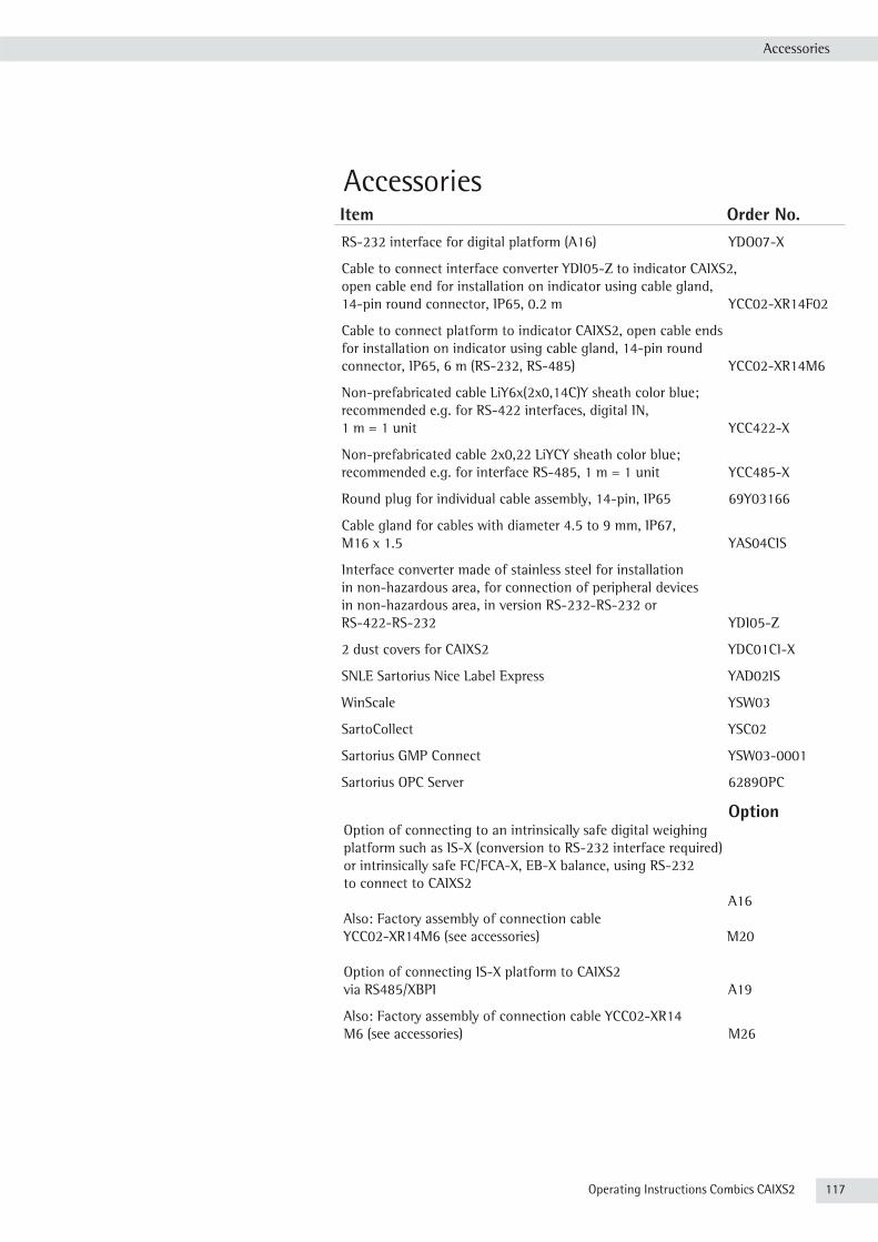
Operating Instructions Combics CAIXS2 117
Accessories
AccessoriesItem Order No.RS-232 interface for digital platform (A16) YDO07-X
Cable to connect interface converter YDI05-Z to indicator CAIXS2, open cable end for installation on indicator using cable gland, 14-pin round connector, IP65, 0.2 m YCC02-XR14F02
Cable to connect platform to indicator CAIXS2, open cable ends for installation on indicator using cable gland, 14-pin round connector, IP65, 6 m (RS-232, RS-485) YCC02-XR14M6
Non-prefabricated cable LiY6x(2x0,14C)Y sheath color blue; recommended e.g. for RS-422 interfaces, digital IN, 1 m = 1 unit YCC422-X
Non-prefabricated cable 2x0,22 LiYCY sheath color blue; recommended e.g. for interface RS-485, 1 m = 1 unit YCC485-X
Round plug for individual cable assembly, 14-pin, IP65 69Y03166
Cable gland for cables with diameter 4.5 to 9 mm, IP67, M16 x 1.5 YAS04CIS
Interface converter made of stainless steel for installation in non-hazardous area, for connection of peripheral devices in non-hazardous area, in version RS-232-RS-232 or RS-422-RS-232 YDI05-Z
2 dust covers for CAIXS2 YDC01CI-X
SNLE Sartorius Nice Label Express YAD02IS
WinScale YSW03
SartoCollect YSC02
Sartorius GMP Connect YSW03-0001
Sartorius OPC Server 6289OPC
OptionOption of connecting to an intrinsically safe digital weighing platform such as IS-X (conversion to RS-232 interface required) or intrinsically safe FC/FCA-X, EB-X balance, using RS-232 to connect to CAIXS2 A16Also: Factory assembly of connection cable YCC02-XR14M6 (see accessories) M20
Option of connecting IS-X platform to CAIXS2 via RS485/XBPI A19
Also: Factory assembly of connection cable YCC02-XR14 M6 (see accessories) M26
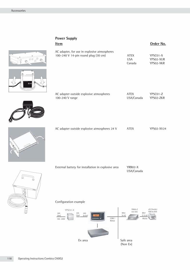
118 Operating Instructions Combics CAIXS2
Konfigurationsbeispiel Combics 2 EX - FM
100- 240V
Sicherer Bereich (NON Ex)
YPS02-XUR inkl. (3m)
inkl. (3m)
YDI05-Z mit A25
z.B. Drucker YDP14-OCE
COM 1 RS422
M54 (x m)
inkl. (0,3m)
M57 (1,5 m)
RS232
FM Class I, Div 1
Anschlüsse
Accessories
Power SupplyItem Order No.
AC adapter, for use in explosive atmospheres 100–240 V 14-pin round plug (30 cm) ATEX YPSC01-X USA YPS02-XUR Canada YPS02-XKR
AC adapter outside explosive atmospheres ATEX YPSC01-Z100-240 V range USA/Canada YPS02-ZKR
AC adapter outside explosive atmospheres 24 V ATEX YPS02-XV24
External battery for installation in explosive area YRB02-X USA/Canada
Configuration example
Ex area Safe area (Non Ex)
Installation Instructions | Betriebsanleitung
Sartorius YPSC01-XConfigurable power supply and communication system for use inside hazardous areas Konfigurierbares Netzgerät und Kommunikationssystem für den Einsatz innerhalb des explosionsgefährdeten Bereichs
Sartorius YPSC01-ZConfigurable power supply and communication system for use outside hazardous areas, onlyKonfigurierbares Netzgerät und Kommunikationssystem nur für den Einsatz außerhalb des explosionsgefährdeten Bereichs
98647-004-37
InstallationConnecting the Device to AC Power
!Before startup, make sure that the power cable is properly connected to the poweroutlet. In particular, the protective conductor must be connected to the housingof the power supply.
Connect all devices via their equipotential bonding conductor terminals to theequipotential bonding conductor. Installation must be carried out properly bytrained personnel and according to the standards of the technology.
!The system should only be operated for the first time when it is certain that thearea is not potentially explosive. If deviations are evident during startup due totransport damage, the system should be disconnected from the power supply andService should be contacted (no display, no backlighting despite weight valuedisplay, no reproducibility of the weight value, no stability in the display, etc.)
!Cabling:– Both cables should be laid fixed– Flexible cabling with screws available upon request
t Check the supply voltage/frequency and plug design.Contact your Sartorius dealer if they do not match.
!When operating a balance in an explosive area:– Follow all current standards and regulations for the installation of devices in the
explosive area.– Device installation should be carried out by trained personnel and checked
properly.
!Before startup, connect the linked devices to a central equipotential busbar.
h Only use cables and cable lengths approved by Sartorius,cables not provided by Sartorius are the responsibility of the operator.
6 YPS02-X.. Installation Instructions
Installation
Page 20
Power Supplies for Signum® 3 Ex Supreme
ATEX Zone 20/1/21/2/22 Safe Area: YPSC01-Z
YPSC01-X Associated Intrinsically Safe (AIS) to connect to ATEX Zone 20/1/21/2/22
FM Class I,II,III Div 1,2 Safe Area: YPS02-ZKR
YPS02-XUR AIS to connect to
CSA Class I,II,III Div 1,2 FM /CSA Class I,II,III Div 1,2
YPS02-XKR
ATEX Zone 20/1/21/2/22 Safe Area: YPS02-XV24
YPS02-XV24 AIS to connect toATEX Zone 20/1/21/2/22
ATEX Zone 20/1/21/2/22FM Class I,II,III Div 1,2
YRB02-X
Pow
er S
uppl
ies
100
-24
0 V
Rech
arge
able
Ba
tter
yPo
wer
Sup
ply
24V
26. November 2012
98647-003-43
Operating Instructions | Betriebsanleitung
Sartorius YRB02-XEx Rechargeable Battery Pack (External Explosion-protected Rechargeable Battery Pack)Ex-Akku-Pack (externer wiederaufladbarer Ex-geschützter Akku-Pack)
YPSC01-X

Operating Instructions Combics CAIXS2 119
Declaration of Conformity
“Installation”, a Service Offered by Sartorius“Installation” Service in GermanyOur “Installation" service package provides the following services:– Installation– Commissioning– Inspection– Training
If you would like Sartorius to install the indicator, please request this service from a customer service employee.

120 Operating Instructions Combics CAIXS2
Declarations of Conformity

Operating Instructions Combics CAIXS2 121
Declaration of Conformity

122 Operating Instructions Combics CAIXS2

Operating Instructions Combics CAIXS2 123

Sheet of
2013-08-08
Dr. D. Klausgrete
In the following the expression „device“ refers to the indicator type CAIXS2. The expression „equipment“ refers to the indicator type CAIXS2 and to the other connected devices.
1) Install the equipment in compliance with applicable laws, rules and regulations, ordinances and standards. In particular, be sure to conform to the European Standards EN 60079-14 (Explosive atmospheres – Part 14: Electrical installations design, selection and erection). For more information see „Verification of Intrinsic Safety“ 66015-751-60 (ATEX) and „Control Drawing“ 66015-751-07 (for use in the USA and in Canada).
2) Be sure to follow the installation, operating, maintenance and servicing instructions for the connected devices given in the manuals supplied 66015-751-16-A4-R00.pdf.
3) The device shall be installed in such a way that it is protected against the entry of solid foreign objects or water capable of impairing the safety of the apparatus. Reduce the risk of mechanical damage to a minimum.
4) The equipment must be powered by a suitable certified/approved power supply or battery pack with intrinsically safe circuits as described in the certificate of this equipment.
5) Exposure to UV radiation is not allowed!6) Prior to opening the equipment, disconnect the power supply or make sure that there is no potentially explosive
atmosphere or any other explosion hazard in the surrounding area!7) The data cables connected to the equipment are considered as intrinsically safe circuits. The connections are
secured against accidental disconnections and may only be plugged in or disconnected when the power is switched completely off.
8) Output not used must be safeguarded by appropriate sealing cap (maybe in the scope of delivery) so that the IP6x protection rating is maintained.
9) The injection of any external voltage must be avoided by suitable installation of the connected cables!10) Check the correct function of the data transfer before you use the equipment in a hazardous location. 11) If the equipment does not operate properly, unplug it immediately from line power (mains supply)! If the device
shows visible damages, unplug it and make sure that it will not be used anymore.12) All metal parts must be electrically connected to the terminal for the equipotential bonding conductor (PA). The
equipment operator is obligated to connect a lead with a gauge of at least 4 mm² (cross section) to the PA terminal located on the side of the housing. The low resistance of this connection to the PA busbar must be checked when the system is installed at the intended place of use. The shielding of the connecting cables may only be used for grounding when no impermissible difference in voltage is generated and, if necessary, the shielding is able to conduct the equipotential current.
13) Avoid generating static electricity. Use only a damp cloth to wipe down the equipment. The equipment operator shall be responsible for preventing any risks caused by static electricity.
14) Keep chemicals and other agents, which can corrode the housing seals and cable sheaths, away from the equipment. These agents include oil, grease, benzene, acetone and ozone. If you are not sure about the safety of a certain substance, please contact the manufacturer.
15) Use equipment only in the temperature ranges indicated. Avoid exposing the equipment to heat.16) The equipment operator is responsible for any non-Sartorius cables used.17) Check the EX approval marking (particularly the group for gases/dusts and temperature class/code) on all
equipment in the hazardous area before operation to ensure that this approved equipment is permitted to be operated in this area.
18) At reasonable intervals, have your equipment installation checked for proper functioning and safety by a trained and certified technician.
19) If your equipment needs to be repaired, use only original spare parts supplied by the manufacturer!20) Any tampering with the equipment by anyone, other than repair work done by authorized Sartorius service
technicians, will result in the loss of EX conformity and in the forfeiture of all claims under the manufacturer's warranty. Only authorized specialists may open the equipment by working to Sartorius rule.
21) Modifications, including those to be carried out by Sartorius employees, may be permitted only after the express written authorization has been obtained from Sartorius.
22) If the housing has been opened, close the housing with a tightening torque of 1 Nm.23) If the housing has been opened again after the first field wiring, the gasket must be replaced!

Operating Instructions Combics CAIXS2 125

126 Operating Instructions Combics CAIXS2
Menu Structure
Menu StructureOverview of the complete menu structure; the individual setting parameters are listed on the following pages.The indicator only displays the menus that correspond to the available hardware. APPLIC. Set and select applications (see page 137)
- APPLIC.1 Basic weighing function, Counting applications z , Neutral measurement znM, Animal weighing j, Weighing in percent %
- APPLIC.2 Checkweighing +/- , Classification Wapplications - APPLIC.3 Net-total formulation R , Totalizing s applications - AUT.TARE Automatic taring: 1. weight tared- MIN.TARE Minimum load for automatic tare and printout- AUT.STRT Automatic start of application- CLER.CF Selective deleting with the C key- TARE.FCT Tare function- RESET Factory settings for all applications
FN-KEY Defines functions of the k key (see page 141)
- off
- 2ND.UNIT
SETUP Adjusts device settings to user requirements (see page 141)
- WP1 Settings for weighing platform 1- COM1 Settings for the RS-232 interface- CTRL IO Universal input setting- PRINT Printout settings- UTILIT. Settings for additional functions- TIME Time setting - DATE Date setting- U-CODE User password entry for locking the Setup menu- S-DATE only visible in Service mode; applications- SER.NO. only visible in Service mode; serial number- MODEL only visible in Service mode; serial number- S-SQMIN only visible in Service mode; - SQMIN Activates display or GMP-compliant printout- ALIB.MEM
INFO Displays device-specific information (see page 151)
- SERVICE Service date- TERM Indicator serial number- WP-1 Weighing platform 1 device data- WP-2 Weighing platform 2 device data- FLEXINF FlexPrint settings- ALIB.MEM Alibi memory settings
LANGUAG. Language setting for display and printout (see page 151)
- DEUTSCH
- ENGLISH
- US.MODE
- FRANC
- ITAL
- ESPANOL
- CODES
ADC.CON ADC configuration settings (see page 152)
- VERIF.
- STANDARD

Operating Instructions Combics CAIXS2 127
Menu Structure
Menu Applications* = Factory setting
APPLIC./ APPLIC.1 WEIGH. Weighing
APPLIC./APPLIC.1/ COUNT. Counting MIN.INIT Minimum load for application 3.6
1 DIGIT 1 scale interval 3.6.1* 2 DIGIT 2 scale intervals 3.6.2 ... see “Weighing" 1000 d 1000 scale intervals 3.6.10
RESOLUT Resolution for calculation of reference value 3.9 DISP.ACC. Display accuracy 3.9.1* 10 FOLD plus 1 decimal place (10 fold) 3.9.2 100 FOLD plus 2 decimal places (100 fold) 3.9.3
SAVE WT. Parameter for saving weight values 3.11 STABIL With stability* 3.11.1 ACC.STAB With increased stability* 3.11.2
REF.UPDT Reference sample updating 3.12 OFF Off 3.12.1 AUTOMAT Automatic 3.12.3*
REF.WP Reference weighing instrument 3.13 NO WP No weighing platform selected 3.13.1* WP 1 Weighing platform 1 3.13.2 WP 2 Weighing platform 2 3.13.3

128 Operating Instructions Combics CAIXS2
Menu Structure
REF.WP Reference weighing instrument 3.13 NO WP No weighing platform selected 3.13.1* WP 1 Weighing platform 1 3.13.2 WP 2 Weighing platform 2 3.13.3
APPLIC/APPLIC.1 neutr.m Neutral Measurement MIN.INIT Minimum load for application 3.6
1 DIGIT 1 scale interval 3.6.1* 2 DIGIT 2 scale intervals 3.6.2 ... see “Weighing" 1000 d 1000 scale intervals 3.6.10
RESOLUT Resolution for calculation of reference value 3.9 DISP.ACC. Display accuracy 3.9.1* 10 FOLD plus 1 decimal place (10 fold) 3.9.2 100 FOLD plus 2 decimal places (100 fold) 3.9.3
DEC.PLCS Decimal place in displayed result 3.10 WITHOUT none 3.10.1 1 Dec.Pl 1 decimal place 3.10.2 2 Dec.Pl. 2 decimal places 3.10.3 3 Dec.Pl. 3 decimal places 3.10.4
SAVE WT. Parameter for saving weight values 3.11 STABIL With stability* 3.11.1 ACC.STAB With increased stability* 3.11.2
REF.WP Reference weighing instrument 3.13 NO WP No weighing platform selected 3.13.1* WP 1 Weighing platform 1 3.13.2 WP 2 Weighing platform 2 3.13.3
APPLIC./ APPLIC.1 ANIM.WG. Animal Weighing (Averaging) MIN.INIT Minimum load for application 3.6
1 DIGIT 1 scale interval 3.6.1* 2 DIGIT 2 scale intervals 3.6.2 ... see “Weighing" 1000 d 1000 scale intervals 3.6.10
START Start averaging 3.18 MANUAL manual 3.18.1* AUTOMAT automatic 3.18.2*
ACTIVTY Animal activity 3.19 0.1 PERC. 0.1% of animal/object 3.19.1 0.2 PERC. 0.2% of animal/object 3.19.2* 0.5 PERC. 0.5% of animal/object 3.19.3 1 PERC. 1% of animal/object 3.19.4 2 PERC. 2% of animal/object 3.19.5 5 PERC. 5% of animal/object 3.19.6 10 PERC. 10% of animal/object 3.19.7 20 PERC. 20% of animal/object 3.19.8 50 PERC. 50% of animal/object 3.19.9 100 PERC. 100% of animal/object 3.19.10
PRINT Automatic printout 3.20 MANUAL manual 3.20.1* AUTOMAT automatic 3.20.2*
DIS.UNLD Static display of result after load removed 3.21 CLEARED Display is fixed until unload threshold reached 3.21.1* PRESENT fixed display until c is pressed 3.21.2
APPLIC./ APPLIC.1 percent Weighing in Percent MIN.INIT Minimum load for application 3.6
1 DIGIT 1 scale interval 3.6.1* 2 DIGIT 2 scale intervals 3.6.2 ... see “Weighing” 1000 d 1000 scale intervals 3.6.10
RESOLUT Resolution for calculation of reference value 3.9 DISP.ACC. Display accuracy 3.9.1* 10 FOLD plus 1 decimal place (10 fold) 3.9.2 100 FOLD plus 2 decimal places (100 fold) 3.9.3

Operating Instructions Combics CAIXS2 129
Menu Structure
DEC.PLCS Decimal place in displayed result 3.10 WITHOUT none 3.10.1 1 Dec.Pl 1 decimal place 3.10.2 2 Dec.Pl. 2 decimal places 3.10.3 3 Dec.Pl. 3 decimal places 3.10.4
SAVE WT. Parameter for saving weight values 3.11 STABIL With stability* 3.11.1 ACC.STAB With increased stability* 3.11.2
REF.WP Reference weighing instrument 3.13 NO WP No weighing platform selected 3.13.1* WP 1 Weighing platform 1 3.13.2 WP 2 Weighing platform 2 3.13.3
CALC.DIS Calculated values display 3.15 RESIDUE Residue 3.15.1* LOSS Calculation 3.15.2
APPLIC./ APPLIC.2 OFF
APPLIC./ APPLIC.2 CHECK.WG Checkweighing CHECK.RG Checkweighing range 4.2
30-170% 30 to 170% 4.2.1* 10-MAX.L 10% to infinity 4.2.2
CTRL.SET Activate SET control output 4.3 OUTPUT “SET" output 4.3.1* OP.READY Ready to operate (for process control systems) 4.3.2
OUTP.ACT Port lines 4.4 OFF off 4.4.1 ALWAYS always 4.4.2 STABIL on at stability 4.4.3 CHECK.RG on within checkweighing range 4.4.4* STAB.CHK On at stability within checkweighing range 4.4.5
INPUT Parameter input 4.5 TAR.MN.MX Min, Max, target value 4.5.1* TARG.PER. Only target value with percent limits 4.5.2 TAR.A.PER Target value with asymmetrical percent limits 4.5.3 TAR.TOL Target value with relative tolerances 4.5.4
AUT.PRNT Automatic printing 4.6 OFF off 4.6.1* ON on 4.6.2 OK Only values within tolerance 4.6.3 NOT OK Only values outside tolerance 4.6.4
APP.ZERO Checkweighing toward zero 4.7 OFF off 4.7.1* ON on (Symbol Y is displayed) 4.7.2
APPLIC./APPLIC.2 CLASS. Classification PARAM.1 Parameter 1
MIN.INIT Minimum load for application 3.6 1 DIGIT 1 scale interval 3.6.1* 2 DIGIT 2 scale intervals 3.6.2 ... see “Weighing" 1000 d 1000 scale intervals 3.6.10
PARAM.2 Parameter 2
CTRL.SET Activate SET control output 4.3 OUTPUT “SET" output 4.3.1* OP.READY Ready to operate (for process control systems) 4.3.2
OUTP.ACT Port lines 4.7 OFF off 4.7.1 ALWAYS always 4.7.2 STABIL on at stability 4.7.3*
QTY. Number of classes 4.8 3 CLASS 3 classes 4.8.1* 5 CLASS 5 classes 4.8.2
INPUT Parameter input 4.9 WEIGHTS Weight values 4.9.1* PERC.TAG Percentage values 4.9.2

130 Operating Instructions Combics CAIXS2
Menu Structure
PRINT Automatic printing 4.10 MANUAL manual 4.10.1* AUTOMAT automatic 4.10.2*
Applic.3 off
APPLIC/ APPLIC.3 NET.TOT. Net-Total MIN.INIT Minimum load for application 3.6
1 DIGIT 1 scale interval 3.6.1* 2 DIGIT 2 scale intervals 3.6.2 ... see “Weighing" 1000 d 1000 scale intervals 3.6.10
PRT.SAV. Individual/Component printout when saved 3.17 OFF Automatic printing off 3.17.1 EACH.TIM. Print the entire standard print configuration every time with the O key function 3.17.2* ONCE Print the entire standard print configuration once with the O key 3.17.3
Applic./Applic.3/TOTALIZ Totalizing MIN.INIT Minimum load for application 3.6
1 DIGIT 1 scale interval 3.6.1* 2 DIGIT 2 scale intervals 3.6.2 ... see “Weighing" 1000 d 1000 scale intervals 3.6.10
AUTO.SAV Autosave 3.16 OFF Off 3.16.1* ON On 3.16.2
PRT.SAV. Individual/Component printout when saved 3.17 OFF Automatic printing off 3.17.1 EACH.TIM. Print the entire standard print configuration every time with the O key function 3.17.2* ONCE Print the entire standard print configuration once with the O key 3.17.3
VAL.FROM Value source for automatic saving 3.22 APPL. 1 Application 1 3.22.1* APPL. 2 Application 2 3.22.2
SAV.VAL. Save value 3.23 NET Net 3.23.1* CALCUL. Calculation 3.23.2 NET+CAL Net and calculated 3.23.3
APPLICATION / AUT.TARE Automatic taring AUT.TARE 1st Weight tared 3.7
OFF Off 3.7.1* ON On 3.7.2
APPLICATION/MIN.TARE Minimum load for automatic taring and automatic printing MIN.TARE Minimum load for automatic taring and printing 3.5
1 DIGIT 1 scale interval 3.5.1* 2 DIGIT 2 scale intervals 3.5.2 ... see “Weighing" 1000 d 1000 scale intervals 3.5.10
APPLICATION / AUT.STRT For"On" automatic start of application with the last saved initialization data AUT.strt Automat. start of application with the last saved settings 3.8
AUTOMAT Automatic (on) 3.8.1* MANUAL manual (off) 3.8.2
APPLIC./CLER.CF Selective deleting with the c key CLER.CFSelective deleting with the c key 3.24
ALL.APPL. Deletes all applications 3.24.1* SEL.APPL Only deletes selected application 3.24.2
APPLIC. / TARE.FNC Tare function TARE.FNC Tare function settings 3.25
NORMAL Can add a preset tare if tare value is available; however no tare function possible 3.25.1*
SPECIAL When a preset tare is entered, the tare value is deleted; however, tare function activation is possible 3.25.2

Operating Instructions Combics CAIXS2 131
Menu Structure
APPLIC. / RESET Resets all applications to factory settings RESET Restore all applications to factory default settings 9.1
YES Yes (restore factory settings) 9.1.1
NO No (retain user-defined settings) 9.1.2*
Menu Key Assignment for the k Key
* = Factory settings fn-key OFF k key not assigned 2ND.UNIT Display 2nd unit* SQMIN
Setup Menu (Device Settings) setup / WP-1 / RS-232 Depending on the connected complete scale SBI-STDS / SBI.EICH / XBPI.232 / ADU-232
setup / WP-1 / RS-485 Depending on the connected complete scale IS-485 / ADU-485
setup / WP-1 / intern. Param.1
AMBIENT Adapting the scale to ambient conditions (filter adjustment) 1.1 V.STABLE very stable 1.1.1 STABLE stable 1.1.2* UNSTABLE unstable 1.1.3 V.STABLE very stable 1.1.4
APP.FILT application filter 1.2 FINAL.RD. final readout 1.2.1* FILLING filling mode 1.2.2 REDUC. low filtering 1.2.3 OFF without filtering 1.2.4
Stab.Rng Stability range 1.3 MAX.ACC. maximum accuracy (1/4 digit) 1.3.1* V.ACC. very accurate (1/2 digit) 1.3.2 ACC. accurate (1 digit) 1.3.3 FAST fast (2 digits) 1.3.4 V.FAST very fast (4 digits) 1.3.5 MAX.FAST. maximum speed (8 digits) 1.3.6
STAB. DLY Stability delay 1.4 NONE no delay 1.4.1 SHORT short delay 1.4.2* MEDIUM medium-length delay 1.4.3 LONG long delay 1.4.4
TARE Tare mode 1.5 W/O.STAB on 1.5.1 AFT.STAB off 1.5.2*
Aut.zero Auto zero 1.6 ON on 1.6.1* OFF off 1.6.2
1.WT.UNIT Weight unit (depends on the weighing platform type) 1.7 1))not for use in legal metrology GRAM gram/g 1.7.2* KILOGR. Kilograms/kg 1.7.3 CARAT carats/ct1) 1.7.4 POUND pounds/lb1) 1.7.5 OUNCE ounces/oz1) 1.7.6 TROY.OZ. troy ounces/ozt1) 1.7.7 HK TAEL Hong Kong taels/tlh1) 1.7.8 SNG.TAEL Singapore taels/tls1) 1.7.9 TWN.TAEL Taiwan taels/tlt1) 1.7.10 GRAIN Grains/GN1) 1.7.11 PENNY.WT. Pennyweights/dwt1) 1.7.12 MILLIGR. Milligrams/mg1) 1.7.13 PART./PD Parts per Pound//lb1) 1.7.14 CHN.TAEL Chinese taels/tlc1) 1.7.15 MOMME Mommes/mom1) 1.7.16 KARAT Austrian karats/K1) 1.7.17

132 Operating Instructions Combics CAIXS2
Menu Structure
TOLA Tola/tol1) 1.7.18 BAHT Baht/bat1) 1.7.19 MESGHAL Mesgahl/MS1) 1.7.20 TON tons/t 1.7.21
1.DIS.DIG. Display accuracy 1.8 ALL all digits 1.8.1* -1.WT.CHA reduced by one digit 1.8.2 RES.*10 10-fold increased resolution 1.8.14 +DIV. 2 Increase resolution by 2 scale intervals 1.8.15 +DIV. 1 Increase resolution by 1 scale interval 1.8.16
CAL.ADJ Calibration, adjustment 1.9 CAL.EXT. External calibration/adjustment with default weight 1.9.1* CAL.E.AUT. External cal./adjustment, weight is detected (see 1.18.1) 1.9.2 CAL.E.USR. External calibr./adjustment with user-defined weight 1.9.3 CAL.INT. Internal calibration/adjustment (for IS scales only) 1.9.4 INT.LIN. Internal linearization (for IS scales only) 1.9.51)
EXT.LIN. External linearization with default weights 1.9.61)
LIN.E.USR External linearization with user-defined weights 1.9.71)
SET.PREL. Set the preload 1.9.8 DEL.PREL. Delete the preload 1.9.9 BLOCKED Key blocked 1.9.10
CAL.SEQ. Calibration/adjustment sequence 1.10 AUTOMAT Calibration with automatic adjustment 1.10.1 MANUAL Calibration with manual adjustment 1.10.2*
ZERORNG. Zero range 1.11 1 PERC. 1 percent/max.load 1.11.1 2 PERC. 2 percent/max.load 1.11.2 5 PERC. 5 percent/max.load 1.11.3*
INIT.ZER. Zero at power on 1.12 1 PERC. 1 percent/max.load 1.12.1* 2 PERC. 2 percent/max.load 1.12.2 5 PERC. 5 percent/max.load 1.12.3
ON.TARE Tare/zero at power on 1.13 ON On 1.13.1* OFF Off 1.13.2
ISOCAL Adjustment prompt 1.15 OFF Off 1.15.1* ADJ.PROM On 1.15.2
CAL.EXT External calibration/adjustment 1.16 ACTIVATED Activated 1.16.1* BLOCKED Blocked 1.16.2
CAL.UNIT Weight unit for calibration 1.17 GRAM gram 1.17.1* KILOGR. Kilogram 1.17.2 TONS ton 1.17.3 POUND pound 1.17.4
MAN.EXT.W Manual entry of external weights 1.18 Cal.Adj. cal/adj. weight 1.18.1 LIN.WT.1 linearization weight 1 1.18.21)
LIN.WT.2 linearization weight 2 1.18.31)
LIN.WT.3 linearization weight 3 1.18.41)
LIN.WT.4 linearization weight 4 1.18.51)
ADJ.W/O.W Adjustment without weights1) 1.19 NOM.LOAD Nominal load 1.19.1 RESOLUT resolution 1.19.2 SENSIT.1 Sensitivity 1 1.19.3 SENSIT.2 Sensitivity 2 1.19.4 SENSIT.3 Sensitivity 3 1.19.5 SENSIT.4 Sensitivity 4 1.19.6 ZER.POIN Zero point 1.19.7 SAVE Save parameters 1.19.8
GEOG.DAT Geographical data1) 1.20 LATITUD latitude 1.20.1 ALTITUD altitude 1.20.2 GRAVITY gravitational acceleration 1.20.3 SAVE Save parameters 1.20.4
1) Only in Service mode

Operating Instructions Combics CAIXS2 133
Menu Structure
setup / WP-1 / intern. Param.2
2ND.UNIT 2nd weight unit (depends on the weighing platform type) 3.1 1)not for use in legal metrology GRAM gram/g 3.1.2* KILOGR. Kilograms/kg 3.1.3 CARAT carats/ct1) 3.1.4 POUND pounds/lb1) 3.1.5 OUNCE ounces/oz1) 3.1.6 TROY.OZ. troy ounces/ozt1) 3.1.7 HK TAEL Hong Kong taels/tlh1) 3.1.8 SNG.TAEL Singapore taels/tls1) 3.1.9 TWN.TAEL Taiwan taels/tlt1) 3.1.10 GRAIN Grains/GN1) 3.1.11 PENNY.WT. Pennyweights/dwt1) 3.1.12 MILLIGR. Milligrams/mg1) 3.1.13 PART./PD Parts per Pound//lb1) 3.1.14 CHN.TAEL Chinese taels/tlc1) 3.1.15 MOMME Mommes/mom1) 3.1.16 KARAT Austrian karats/K1) 3.1.17 TOLA Tola/tol1) 3.1.18 BAHT Baht/bat1) 3.1.19 MESGHAL Mesgahl/MS1) 3.1.20 TON Tons/t 3.1.21
2.DIS.DIG. Display accuracy 3.2 ALL all digits 3.2.1* -1.WT.CHA reduced by 1 decimal place for load change 3.2.2 RES.*10 10-fold increased resolution 3.2.14 +DIV. 2 Increase resolution by 2 scale intervals 3.2.15 +DIV. 1 Increase resolution by 1 scale interval 3.2.16
setup / WP-1 / intern. RESET Factory settings WT.PARA Restore factory default settings 9.1
NO No 9.1.1* YES Yes 9.1.2
setup / WP-1 / intern. ADC-CON Analog/Digital converter configuration (ADC)1)
STANDRD. Standard VERIF. Verifiable
SETUP / WP-1 / OFF
setup /com-1 off
setup /com-1 WP-2 Weighing platform 2 RS-232*
SBI.STd
SBI.Eich
xBPI-232
ADU-232
Menus 1.1 to 1.8 same as for WP1 Calibration/Adjustment 1.9 External calibration/adjustment; default weight* 1.9.1 External calibration/adjustment; weight can be selected (1.18.1) 1.9.3 Internal cal/adj 1.9.4 J key locked 1.9.10 Menus 1.10 to 9.1 same as for WP1 ADC-232 Menus 1.1 to 9.1 same as for WP11) Only in Service mode

134 Operating Instructions Combics CAIXS2
Menu Structure
setup /com-1 dat.prot Data protocols Config. SBI*
BAUD Baud rate 5.1 150 150 5.1.1 300 300 5.1.2 600 600 5.1.3 1200 1200 5.1.4 2400 2400 5.1.5 4800 4800 5.1.6 9600 9600 5.1.7* 19200 19200 5.1.8
PARITY Parity 5.2 SPACE Space Only if 7 data bits is selected 5.2.2 ODD Odd 5.2.3* EVEN Even 5.2.4 NONE None 5.2.5
STOPBIT Number of stop bits 5.3 1 STOP 1 stop bit 5.3.1* 2 STOP 2 stop bits 5.3.2
HANDSHK Handshake mode 5.4 SOFTW. Software handshake 5.4.1 HARDW. Hardware handshake, 1 character after CTS 5.4.3*
DATABIT Number of data bits 5.6 7 bits* 5.6.1 8 bits 5.6.2
MAN./AUT. Data output (manual/automatic) 6.1 IND.W/O Manual, without stability 6.1.1 IND.AFTR Manual, at stability 6.1.2* AUT. W/O Automatic, without stability 6.1.4 AUT.WITH Automatic, with stability 6.1.5 PROT.PRN Protocol printout for computer (PC) 6.1.7
AUT.CYCL Time-dependent automatic data output 6.3 EACHVAL 1 display update 6.3.1* AFTR.2 2 display updates 6.3.2 AFTR.10 10 display updates 6.3.4 AFTR.100 100 display updates 6.3.7
LINE Data output: Line format 7.2 16. CHAR For raw data: 16 characters 7.2.1 22. CHAR For other applications: 22 characters 7.2.2*
SIGN Data output: Sign format 7.3 + DEACT. Plus sign deactivated 7.3.1 + ACT. Plus sign activated 7.3.2*
SETTING Factory settings for COM1: SB 9.1 YES Yes 9.1.1 NO No* 9.1.2
xBPI-232
SMA
BAUD Baud rate 5.1 150 150 5.1.1 300 300 5.1.2 600 600 5.1.3 1200 1200 5.1.4 2400 2400 5.1.5 4800 4800 5.1.6 9600 9600 5.1.7* 19200 19200 5.1.8
Numeric menu 5.2 to 5.6 similar to SBI
* = Factory setting
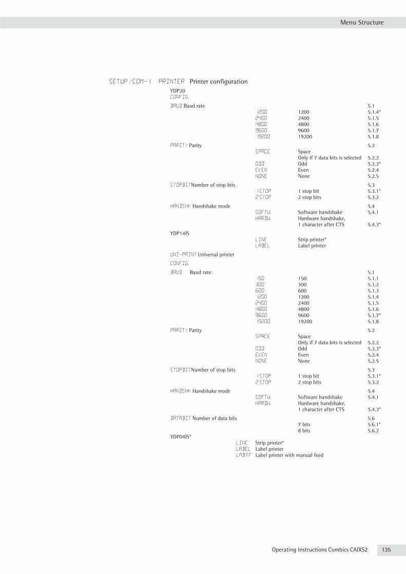
Operating Instructions Combics CAIXS2 135
Menu Structure
SETUP /COM-1 PRINTER Printer configuration YDP20
CONFIG.
BAUD Baud rate 5.1 1200 1200 5.1.4* 2400 2400 5.1.5 4800 4800 5.1.6 9600 9600 5.1.7 19200 19200 5.1.8
PARITY Parity 5.2 SPACE Space Only if 7 data bits is selected 5.2.2 ODD Odd 5.2.3* EVEN Even 5.2.4 NONE None 5.2.5
STOPBITNumber of stop bits 5.3 1 STOP 1 stop bit 5.3.1* 2 STOP 2 stop bits 5.3.2
HANDSHK Handshake mode 5.4 SOFTW. Software handshake 5.4.1 HARDW. Hardware handshake, 1 character after CTS 5.4.3*
YDP14IS LINE Strip printer* LABEL Label printer
UNI-PRINT Universal printer
CONFIG.
BAUD Baud rate 5.1 150 150 5.1.1 300 300 5.1.2 600 600 5.1.3 1200 1200 5.1.4 2400 2400 5.1.5 4800 4800 5.1.6 9600 9600 5.1.7* 19200 19200 5.1.8
PARITY Parity 5.2 SPACE Space Only if 7 data bits is selected 5.2.2 ODD Odd 5.2.3* EVEN Even 5.2.4 NONE None 5.2.5
STOPBITNumber of stop bits 5.3 1 STOP 1 stop bit 5.3.1* 2 STOP 2 stop bits 5.3.2
HANDSHK Handshake mode 5.4 SOFTW. Software handshake 5.4.1 HARDW. Hardware handshake, 1 character after CTS 5.4.3*
DATABIT Number of data bits 5.6 7 bits 5.6.1* 8 bits 5.6.2 YDP04IS* LINE Strip printer* LABEL Label printer LAB FF Label printer with manual feed

136 Operating Instructions Combics CAIXS2
Menu Structure
setup / CTRL IO
Input
Paramet. EXT.KEYB Function for external key 8.4 PRINT Trigger p key function* 8.4.1 PRNT.LNG. Trigger p key function (press and hold) 8.4.2 TARE Trigger ) key function 8.4.3 ISO.TEST Trigger J key function 8.4.4 FN Trigger k key function 8.4.5 SCALE.NR Trigger n key function 8.4.6 OK Trigger O key function 8.4.7 Z/TARE combined zero/tare function 8.4.8 ZERO Trigger ( key function 8.4.9 ON.STBY Trigger e key function 8.4.10 CF Trigger c key function 8.4.11 INFO Trigger I key function 8.4.12 <-D-> Trigger D key function 8.4.13 x10 Trigger K key function 8.4.14 B/G NET Trigger L key function 8.4.15
* = Factory setting

Operating Instructions Combics CAIXS2 137
Menu Structure
setup / print 7
PROTOC. Printouts 7
HEADLIN. Header entry 7.4 LINE 1 Line 1 7.4.1 LINE 2 Line 2 7.4.2 IDENT. 1 Identifier 1 7.4.3 IDENT. 2 Identifier 2 7.4.4 IDENT. 3 Identifier 3 7.4.5 IDENT. 4 Identifier 4 7.4.6 IDENT. 5 Identifier 5 7.4.7 IDENT. 6 Identifier 6 7.4.8
QTY.1 Printout quantity to COM1 7.5 1 PRNT.O 1 printout 7.5.1* 2 PRNT.O 2 printouts 7.5.2
INDIV. 1 Single and results printout for all other applications, user-defined 7.6
COMPON.1 Component printout for net total and totalizing, user-defined 7.71)
TOTAL 1 Totalizing results, user-defined 7.81)
GMP.PROT ISO/GMP printout 7.13 OFF Off 7.13.1* ON On 7.13.2
DAT/TIM Date and time 7.141)
DAT.+TIM Date and time 7.14.1 DAT. ONLY Date only 7.14.2
AUT.ONCE Automatic printout after stability 7.15 OFF Off 7.15.1* ON On 7.15.2
FLEX.PRN FlexPrint 7.16 OFF Off 7.16.1* ON On 7.16.2
DEC.SEP. Weight value decimal separator 7.17 PERIOD Period 7.17.1* COMMA Comma 7.17.2
DAT.RECORD Printout of Alibi and product data memory 7.18 ALL Print all data records 7.18.1 SPEC. Number of data record to be printed (enter no.) 7.18.2*
RESET Reset factory settings

138 Operating Instructions Combics CAIXS2
Menu Structure
setup / UTILIT. 8
PARAMET
Keys Unblock keys 8.3 ALL + Release all 8.3.1* - ALL All blocked 8.3.2 -NUM.PAD Number pad locked 8.3.3 -SCALE.N n key locked 8.3.4 - ZERO key ( locked 8.3.5 - TARE key ) locked 8.3.6 - FN key k locked 8.3.7 -ISO.TST J key locked 8.3.8 - PRINT p key locked 8.3.9 - X10 K key locked 8.3.101)
-B/G.NET L key locked 8.3.111)
- CF c key locked 8.3.121)
- REF r key locked 8.3.131)
- OK O key locked 8.3.141)
-TOGGLE w key locked 8.3.151)
- INFO I key locked 8.3.161)
- <-D-> D key locked 8.3.171)
- ID d key locked 8.3.181)
- MEM R key locked 8.3.191)
AUTO.OFF Automatic shutoff of display and control unit 8.7 TIMER Automatic shutoff via timer (see 8.9) 8.7.1 WITHOUT no automatic shutoff 8.7.2*
BACKLIT Display lighting 8.8 ON On 8.8.1* OFF Off 8.8.2 AUTO.OFF Automatic shutoff via timer (see 8.9) 8.8.3
TIMER Timer for automat. shut-off 8.9 1+1 MIN After 1 minute warning displayed for 1 minute then off 8.9.1* 2+2 MIN After 2 minutes warning displayed for 2 minutes then off 8.9.2 5+5 MIN After 5 minutes warning displayed for 5 minutes then off 8.9.3 Warning information: W 12 flash simultaneously
START.WP Main scale: first platform displayed on start-up 8.11 WP-1 Weighing platform 1 8.11.1* WP-2 Weighing platform 2 8.11.2
DIS.GEOG. Show geographical data before calibration/adjustment 8.12 ON On 8.12.1 OFF Off 8.12.2*
RESET Reset factory settings
setup / time
00.00.00 Enter: hours.minutes.seconds (e.g. 14.10.30), confirm with the ) key
setup / date
00.00.00 Enter: day.month.year (e.g. 13.08.10), confirm with the ) key U.S. mode: month.day.year (e.g. 08.13.10)
setup / u-code
________ Enter, change, delete user password (max. 8 characters)
Only in Service mode: setup / s-date
Date XXX entry
Only in Service mode: setup / ser.no.
2345 Serial number
Only in Service mode: setup / model
CL20001 Model description
Only in Service mode: setup / s-SQmin
Sqmin1
sqmin2
* = Factory setting

Menu Structure
Operating Instructions Combics CAIXS2 139
setup / SQmin
DISPLAY SQmin value display NO No* YES Yes
GMP PRT. GMP-compliant printout NO No* YES Yes
setup / alib.mem
CLEAR Deletes the Alibi memory (Service only) PERIOD Entry of the save intervals in days (0 to 255)
Menu Info (Device Information)* = Factory setting
INFO / SERVICE Service date Input: day.month.year (e.g. 13.08.10), confirm with the )
key U.S. mode: month.day.year (e.g. 08.13.10)
INFO / TERM Indicator cl20001 Model type 12345 Serial number (complete display with the ) key) 01-62-01 Indicator version number (complete display with the ) key) c2 10 200810 Software version (complete display with the ) key) PCB03 Main PC board type
info/WP-1 1st weighing platform 00-42-51 Software version 1st weighing platform 51.53 Geographic latitude in degrees 151 Geographic altitude in meters 9.81 Acceleration of gravity, m/s2 (however no latitude and longitude then) SWITCH Menu access switch
INFO / WP-2 2nd weighing platform (e. g. IS weighing platform) yco0115 Type description of 1st weighing platform 01.02.07 Software version 2nd Weighing platforms 10404354 Serial number 51.53 Geographic latitude in degrees 151 Geographic altitude in meters 8.91 Acceleration of gravity, m/s2
INFO / FLEXINF FlexPrint ------- File name ID--- ID V.--- Version
Language Menu (Language Settings for Display, Calibration and Gmp-Compliant Printouts)
* = Factory setting
LANGUAGE Factory setting: Languag.
deutsch German english English* u.s. mode English with U.S. date/time franc. French ital. Italian espanol Spanish codes Mixed menu display: English and number menu structure
* = Factory setting

Menu Structure
140 Operating Instructions Combics CAIXS2
ADC Settings Menu
ADC.CON
standrd Standard configuration 9.1.3 RANGE Ranges 11.3 SINGLE Single-range scale 11.3.1 MULT.INT Multi-interval scale 11.3.2 MULT.RNG Multiple-range scale 11.3.3 SINGLE Single-range scale 11.4 d Scale interval d 11.4.1 MAX Max. load 11.4.4 MULT.INT Multi-interval scale 11.5 d Scale interval d 11.5.1 RANGE 1 Range 1 11.5.4 RANGE 2 Range 2 11.5.5 RANGE 3 Range 3 11.5.6 MAX Max. load 11.5.7 MULT.RNG Multiple-range scale 11.6 d Scale interval d 11.6.1 RANGE 1 Range 1 11.6.4 RANGE 2 Range 2 11.6.5 RANGE 3 Range 3 11.6.6 MAX Max. load 11.6.7 WT.UNIT Available weight units 11.7 FREE User-defined /o 11.7.1 g Grams /g 11.7.2 kg Kilograms/kg 11.7.4 … t Tons/t 11.7.21 lb Pound:ounces/lb oz 11.7.22 CAL.UNIT Calibration/Adjustment unit 11.8 FREE User-defined /o 11.8.1 g Grams /g 11.8.2 kg Kilograms/kg 11.8.3 ... ... t Tons/t 11.8.21 SAVE Save configuration parameters 11.10 YES Yes 11.10.1 NO No 11.10.2
* = Factory setting
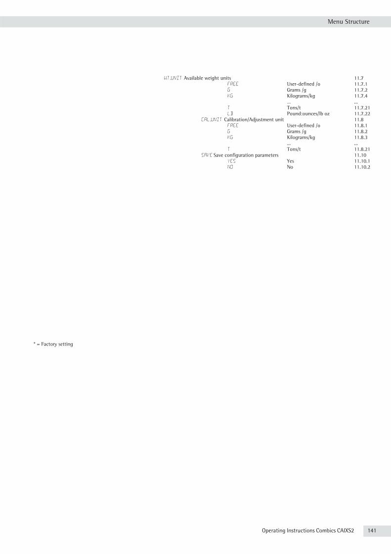
Menu Structure
WT.UNIT Available weight units 11.7 FREE User-defined /o 11.7.1 g Grams /g 11.7.2 kg Kilograms/kg 11.7.4 … ... t Tons/t 11.7.21 lb Pound:ounces/lb oz 11.7.22 CAL.UNIT Calibration/Adjustment unit 11.8 FREE User-defined /o 11.8.1 g Grams /g 11.8.2 kg Kilograms/kg 11.8.3 ... ... t Tons/t 11.8.21 SAVE Save configuration parameters 11.10 YES Yes 11.10.1 NO No 11.10.2
* = Factory setting
Operating Instructions Combics CAIXS2 141

142 Operating Instructions Combics CAIXS2
External Data Interface
External Connections and Data Transfer
CAIXS2 /
Rev. 00Klausgrete2013-08-08
Sheet
of
19
66015-741-50
CAIXS2
YPS02-X.REX Power Supply
(100 -240 Vac)
YPS02-XV24EX Power Supply
(24 Vdc)
YRB02-XEX Rechargeable
Battery Pack
YPS02-Z.REX Power Supply
(100 -240 Vac)
YPS02-XV24EX Power Supply
(24 Vdc)
Power Supply
3m*
0.2m
2m*
20m*
5m*
Notes:*: Customer-made product: up to 20m **: Options up to 40m
5m*
5m
5m
3m
3m
YPSC01-XEX Power Supply
(100 -240 Vac)3m**3m
YPSC01-ZEX Power Supply
(100 -240 Vac)20m**
3m
Non-hazardous areaHazardous area
DC Input Cable
8-contact maleconnector
External Connections and Data Transfer
CAIXS2 /
Rev. 00Klausgrete2013-08-08
Sheet
of
29
66015-741-50
CAIXS2
Option A16:
CAPXS.-... /IUXS4-... / IFXS4-...
weighing platform
CAPXS.-... /IUXS4-... / IFXS4-...
weighing platform
ADUDMS Frontend Board(Option A15; default)
WP Board
Alternative
YCC02-XR14M6connecting cable
Weighing Point (WP) Connection
6m
Option A19:
YCC02-XR14M6connecting cable
6m
Or
Option M20:
Option M26:
Non-hazardous areaHazardous area
Option X2:Separable connection
3m or 6m (depends on model)Alternatelyconnectable
IS......-.X...weighing module
or FC/FCA......-.X...
with RS-232data interface
IS......-.X...weighing module
or FC/FCA......-.X...
with RS-485data interface
J102
WP Board
J101
RS232
RS485
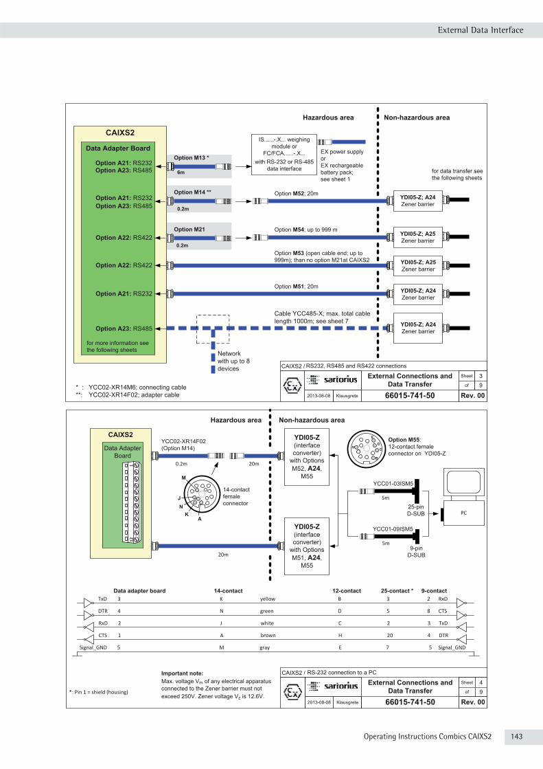
Operating Instructions Combics CAIXS2 143
External Data Interface
External Connections and Data Transfer
CAIXS2 /
Rev. 00Klausgrete2013-08-08
Sheet
of
39
66015-741-50
Option M21
0.2m
Option M14 **
Option M13 *
6m
0.2m
CAIXS2
Data Adapter Board
YDI05-Z; A24Zener barrier
for data transfer see the following sheets
IS......-.X... weighing module or
FC/FCA......-.X...with RS-232 or RS-485
data interface
YDI05-Z; A25Zener barrier
RS232, RS485 and RS422 connections
Option A21: RS232
YDI05-Z; A24Zener barrier
Option M52; 20mOption A21: RS232
Option A23: RS485
Option A23: RS485
Option A22: RS422 YDI05-Z; A25Zener barrier
Option M54; up to 999 m
Option A21: RS232
Option A23: RS485
Non-hazardous areaHazardous area
EX power supplyorEX rechargeable battery pack;see sheet 1
Network with up to 8 devices
Cable YCC485-X; max. total cable length 1000m; see sheet 7
* : YCC02-XR14M6; connecting cable**: YCC02-XR14F02; adapter cable
Option A22: RS422
for more information see the following sheets
YDI05-Z; A24Zener barrier
Option M53 (open cable end; up to 999m); than no option M21at CAIXS2
Option M51; 20m
External Connections and Data Transfer
CAIXS2 /
Rev. 00Klausgrete2013-08-08
Sheet
of
49
66015-741-50
Non-hazardous areaHazardous area
YCC02-XR14F02(Option M14)
YDI05-Z(interfaceconverter)
with Options M52, A24,
M55
YDI05-Z(interfaceconverter)
with Options M51, A24,
M55
YCC01-03ISM5
20m
20m0.2m
5m
PC
Important note:Max. voltage Vm of any electrical apparatus connected to the Zener barrier must not exceed 250V. Zener voltage Vz is 12.6V.
RS-232 connection to a PC
Option M55:12-contact female connector on YDI05-Z
14-contactfemaleconnector
9-pinD-SUB
*: Pin 1 = shield (housing)
TxD 3 K yellow B 3 2 RxD
DTR 4 N green D 5 8 CTS
RxD 2 J white C 2 3 TxD
CTS 1 A brown H 20 4 DTR
Signal_GND 5 M gray E 7 5 Signal_GND
Data adapter board 14-contact 12-contact 25-contact * 9-contact
YCC01-09ISM5
5m
25-pinD-SUB
CAIXS2
Data Adapter Board
12
1
B
E
DCH
J
KN
M
A
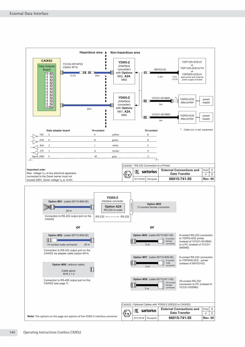
144 Operating Instructions Combics CAIXS2
External Data Interface
External Connections and Data Transfer
CAIXS2 /
Rev. 00Klausgrete2013-08-08
Sheet
of
69
66015-741-50
Connection to RS-485 output port on the CAIXS2 (see page 7)
Optional Cables with YDI05-Z (RS232 to CAIXS2)
Option M51 (cable 65710-806-00)
20 m
Option M5512-contact female connector
Option M56 (cable 65710-807-00)
3 m
Option M52 (cable 65710-808-00)
14-contact male connector 20 m
Option M58 (cable 65710-811-00)
3 m
25-contact femaleconnector
YDI05-Zinterface converter
RS-232 <------------> RS-232
12-c
onta
ct
Connection to RS-232 output port on theCAIXS2 via adapter cable (option M14)
Connection to RS-232 output port on theCAIXS2
9-contact RS-232 connection to YDP03-0CE printer (instead of YCC01-0019M3) or a PC (instead of YCC01-09ISM5)
25-contact RS-232 connection to PC (instead of YCC01-03ISM5)
9-contactfemaleconnector
Option M57 (cable 65710-809-00)
3 m
9-contact RS-232 connection to YDP04IS-0CE.. printer (instead of 69Y03142)
9-contactmaleconnectorOption M50 (without cable)
Cable glandM16 x 1.5
Option A24RS-232 to scale
or or
Note: The options on this page are options of the YDI05-Z interface converter.
External Connections and Data Transfer
CAIXS2 /
Rev. 00Klausgrete2013-08-08
Sheet
of
59
66015-741-50
Non-hazardous areaHazardous area
20m
20m0.2m 1.5m
Important note:Max. voltage Vm of any electrical apparatus connected to the Zener barrier must not exceed 250V. Zener voltage Vz is 12.6V.
RS-232 Connection to a Printer
YDP12IS-0CEUVor
YDP12IS-0CEUVTHor
YDP04IS-0CEUVdata printer with external power supply included
YDP03-0CEdata printer
69Y03142
9-pinD-SUB
YCC01-0016M3
YDP03-0CEdata printer
YCC01-0019M3
power supply
*)
*: Cable incl. in std. equipment
3m
3m
power supply
YDI05-Z(interface converter)
with OptionsM52, A24,
M55
YDI05-Z(interface converter)
with OptionsM51, A24,
M55
YCC02-XR14F02(Option M14)
TxD 3 K yellow B
DTR 4 N green D
RxD 2 J white C
CTS 1 A brown H
Signal_GND 5 M gray E
Data adapter board 14-contact 12-contact
CAIXS2
Data Adapter Board
12
1
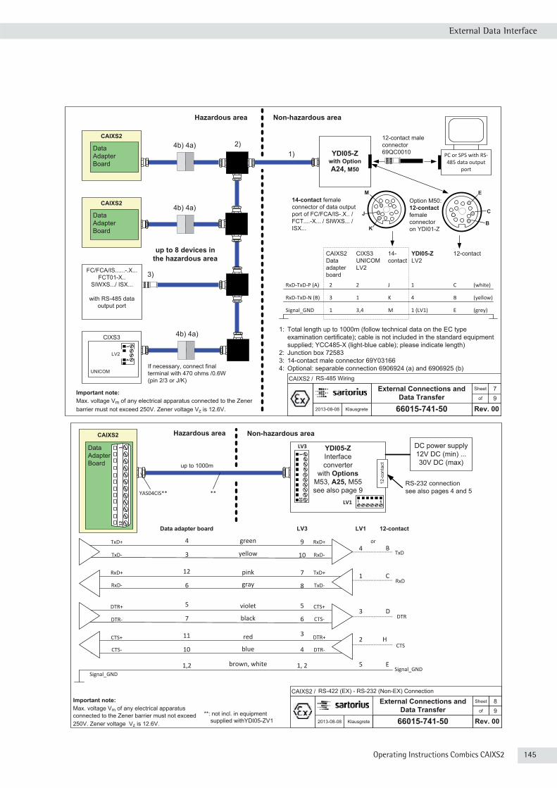
Operating Instructions Combics CAIXS2 145
External Data Interface
External Connections and Data Transfer
CAIXS2 /
Rev. 00Klausgrete2013-08-08
Sheet
of
79
66015-741-50
RS-485 Wiring
Important note:Max. voltage Vm of any electrical apparatus connected to the Zener barrier must not exceed 250V. Zener voltage Vz is 12.6V.
Non-hazardous areaHazardous area
1: Total length up to 1000m (follow technical data on the EC type examination certificate); cable is not included in the standard equipment supplied; YCC485-X (light-blue cable); please indicate length)
2: Junction box 725833: 14-contact male connector 69Y031664: Optional: separable connection 6906924 (a) and 6906925 (b)
up to 8 devices in the hazardous area
FC/FCA/IS......-.X...FCT01-X..
SIWXS.../ ISX...
with RS-485 data output port
1)2)
3)
J
K
MOption M50: 12-contactfemaleconnector on YDI01-Z
14-contact femaleconnector of data output port of FC/FCA/IS-.X.. / FCT....-X... / SIWXS... /ISX...
CIXS3
If necessary, connect final terminal with 470 ohms /0.6W (pin 2/3 or J/K)
PC or SPS with RS-485 data output
port
12-contact male connector69QC0010
4b) 4a)
4b) 4a)YDI05-Z
with Option A24, M50
RxD-TxD-P (A) 2 2 J 1 C (white)
RxD-TxD-N (B) 3 1 K 4 B (yellow)
Signal_GND 1 3,4 M 1 (LV1) E (grey)
CAIXS2 CIXS3 14- YDI05-Z 12-contactData UNICOM contact LV2adapter LV2board
UNICOM
14
LV2
CAIXS2
Data AdapterBoard
4b) 4a)CAIXS2
Data AdapterBoard
B
E
C
External Connections and Data Transfer
CAIXS2 /
Rev. 00Klausgrete2013-08-08
Sheet
of
89
66015-741-50
Non-hazardous areaHazardous area
YDI05-ZInterface converter
with OptionsM53, A25, M55see also page 9
Important note:Max. voltage Vm of any electrical apparatus connected to the Zener barrier must not exceed 250V. Zener voltage Vz is 12.6V.
RS-422 (EX) - RS-232 (Non-EX) Connection
RS-232 connectionsee also pages 4 and 5
Signal_GND
LV3
up to 1000m
TxD+ RxD+
yellow
9
10
green
TxD- RxD-
CTS+ DTR+red 3
4blueCTS- DTR-
1, 2brown, white
LV3 DC power supply12V DC (min) ... 30V DC (max)
**YAS04CIS**
**: not incl. in equipment supplied withYDI05-ZV1
12-c
onta
ct
1 6LV1
B
H
E
12-contact
4
2
5
LV1
TxD
CTS
DTR+ CTS+violet 5
6blackDTR- CTS-D3
DTR
RxD+ TxD+pink 7
8grayRxD- TxD-
C1RxD
101
or
Signal_GND
4
3
11
10
1,2
Data adapter board
5
7
12
6
CAIXS2
DataAdapterBoard
12
1

146 Operating Instructions Combics CAIXS2
External Data Interface
External Connections and Data Transfer
CAIXS2 /
Rev. 00Klausgrete2013-08-08
Sheet
of
99
66015-741-50
Optional Cables with YDI05-Z , option A25
Option M5512-contact female connector
Option M50Cable gland
M16x1.5
Option M53 (cable 65710-856-00)
Country-specific power supply
Connection to RS-422 output port on theCIXS2. Length: up to 999 m permitted.Please indicate the length when ordering.
Option M56 (cable 65710-807-00)
3 m
Option M58 (cable 65710-811-00)
3 m
YDI05-Zinterface converter
RS-422 <------------> RS-232
12-c
onta
ct
9-contact RS-232 connection to YDP03-0CE printer (instead of YCC01-0019M3) or a PC (instead of YCC01-09ISM5)
25-contact RS-232 connection to PC (instead of YCC01-03ISM5)
Option M57 (cable 65710-809-00)
3 m
9-contact RS-232 connection to YDP04IS-0CE.. printer (instead of 69Y03142)
Option M54 (cable 65710-858-00)
14-contact male connector
9-contact femaleconnector
9-contact male connector
25-contactfemaleconnector
Connection to RS-422 output port on the CAIXS2 via adapter cable (CAIXS2 option M21). Length: up to 999 m permitted.Please indicate the length when ordering.
Option A25RS-422 to scale
or or
Note: The options on this page are options of the YDI05-Z interface converter.

Operating Instructions Combics CAIXS2 147
Verification of Intrinsic Safety
Verification of Intrinsic Safety
CAIXS2 /
Rev. 00Klausgrete2013-08-08
Sheet
of
18
66015-751-60
YPS02-Z.RPower supply (100-240 Vac)
II (2) G [EEx ib] IICII (1) D
YPS02-X.RPower supply(100-240 Vac)
II 2 G EEx d [ib] IIC T4II 1 D T135°C IP65
Non-hazardous area
Hazardous area
Alternativeconnections
Power Supply
Sartorius cable; permanently mounted on the power supply / explosion-protected (EX) rechargeable battery pack; cable can be flexibly installed; max. length: 50m
YRB02-XEX battery pack
II 2 G EEx e m [ib]IIC T4II 1 D IP6X T80°C
Circuit Ui Ii Pi Ci LiV_1 12.6 V 133 mA 1.46 W 188 nF 0 mHV_2 12.6 V 133 mA 1.46 W 3 nF 0 mHV_3 8.6 V 187 mA 1.51 W 391 nF 0 mHV_4 12.6 V 150 mA 1.68 W 223 nF 82 µH
YPS02-X.. /YPS02-Z..:Circuit Uo Io Po Co LoV_1 12.6 V 133 mA 1.46 W 1 µF 300 µHV_2 12.6 V 133 mA 1.46 W 1 µF 300 µHV_3 8.6 V 187 mA 1.51 W 4 µF 300 µHV_4 12.6 V 150 mA 1.68 W 1 µF 300 µH
YRB02-X:Circuit Uo Io Po Co LoV_1 12.6 V 133 mA 1.43 W 0.5 µF 300 µHV_2 12.6 V 133 mA 1.43 W 0.5 µF 300 µHV_3 8.6 V 186 mA 1.49 W 0.8 µF 200 µHV_4 12.6 V 150 mA 1.65 W 0.5 µF 300 µH
Zone 1, 2, 21, 22Gas: IIC T4Dust: IIIC
CAIXS2
II 2 G Ex ib IIC T4 GbII 2 D Ex ib IIIC T80°C Db
Verification of Intrinsic Safety
CAIXS2 /
Rev. 00Klausgrete2013-08-08
Sheet
of
28
66015-751-60
Power Supply
Sartorius cable; permanently mounted on the power supply; cable can be flexibly installed; max. length: 50m
YPSC01-X /YPSC01-Z:Circuit Uo Io Po Co LoV_1 12.6 V 115 mA 1.45 W 0.5 µF 350 µHV_2 12.6 V 115 mA 1.45 W 0.5 µF 350 µHV_3 8.6 V 168 mA 1.45 W 0.88 µF 350 µHV_4 12.6 V 134 mA 1.68 W 0.5 µF 350 µHV_5* 8.6 V 168 mA 1.45 W 0.88 µF 350 µH*: not used
Any suitable intrinsically safe Sartorius Equipment
A)
B)
A)
B)YPSC01-XPower supply (100-240 Vac)
II 2 G Ex e mb[ib] IIC T4
II 1D (2)G Ex tD A20 [ib]IIC IP6X T130°C
YPSC01-ZPower supply (100-240 Vac)
II (2) GD [Ex ib] IIC
Non-hazardousarea
Hazardous area
Alternativeconnection
Alternativeconnection
Zone 1, 2, 21, 22Gas: IIC T4Dust: IIIC T80°C
CAIXS2
II 2 G Ex ib IIC T4 GbII 2 D Ex ib IIIC T80°C Db
Note:
A: Connection to main printed circuit board (PCB) 1 in YPSC01-.B: Connection to main PCB 2 in YPSC01-.
Circuit Ui Ii Pi Ci LiV_1 12.6 V 133 mA 1.46 W 188 nF 0 mHV_2 12.6 V 133 mA 1.46 W 3 nF 0 mHV_3 8.6 V 187 mA 1.51 W 391 nF 0 mHV_4 12.6 V 150 mA 1.68 W 223 nF 82 µH

148 Operating Instructions Combics CAIXS2
Verification of Intrinsic Safety
Verification of Intrinsic Safety
CAIXS2 /
Rev. 00Klausgrete2013-08-08
Sheet
of
38
66015-751-60
Ui 13 VIi 425 mAPi 2.0 WCi 4 nFLi 6 µH
Sensor cable for weighing platform Functionality requires cables with a low resistance rating.Recommended: LiYCY 6x...² with 700µH/km maximum, 130nF/km maximum (wire versus wire) and 170nF/km maximum (wire vs. ground) can be installed flexibly up to lengths of 500m. The 6-wire cable, type PR6136, (Lmax = 1.1 mH/km; Cmax = 220nF/km; Rmin = 26 ohms/km) can be used up to 500m.For cables longer than 50m, the screen (shield) of the cable may not be connected to the housing of the weighing platform, or the weighing platform and the indicator must be connected with limited resistivity (e.g., by connecting to an equipotential grounding busbar).
Connection of an Analog Weighing Platform
CAPXS.-......-....IUXS4-......-....., IFXS4-......-.....
Weighing platformII 2 GD EEx ib IIC T4 T155°C
Zone 1, 2, 21, 22Gas: IIC T4Dust: IIIC
CAIXS2
II 2 G Ex ib IIC T4 GbII 2 D Ex ib IIIC T80°C Db
Uo = 11.8 VIo = 147 mAPo = 1.49 WCo = 900 nFLo = 300 µH
Verification of Intrinsic Safety
CAIXS2 /
Rev. 00Klausgrete2013-08-08
Sheet
of
48
66015-751-60
Connection of a Digital Weighing Platform
Note:1: Per circuit2: Combined circuits 3: Versus ground 4: Between the signal lines5: SIWXSBB.-3-06-H.. and ISXBB.-3-06-H.. models may not be used in zone 21
and zone 22 *: Resistively limited
Commercially available shielded cables up to 20 m can be used (e.g., LiYCY).
CAIXS2
II 2 G Ex ib IIC T4 GbII 2 D Ex ib IIIC T80°C Db
RS232 parameters (A/J/K/N/M) 2)
Ui 12.6 V 3) / 25,2 V 4) Uo 10,0 V 3) / 20,0 V 4)
Ii 328 mA* Io 101 mA*Pi any Po 253 mWCi 2,2 nF 3) / 0.5nF 4) Co 3 µF 3) 217nF 4)
Li 0 mH Lo 3 mHL0/Ro 140 µH/
RS485 parameters (J/K/M) 2)
Ui see table 1 Uo 5.2 VIi see table 1 Io 210 mA***Pi any Po 263 mWCi 260 nF Co 78 µFLi 0 mH Lo 600 µH
Lo/Ro 125 µH/
WP Board
Zone 1, 2, 21, 22Gas: IIC T4Dust: IIIC
ISX...-..-..... 5)
II 2 G Ex ib IIC T4 GbII 2 D Ex ib IIIC T80°C Db
RS232 or RS485Data interface
Table 1 (Rmin = Ui / Ii) Ui ±12.4V 12.0V 6.0VIi 130 mA*** 164mA*** anyRmin 95 73 ---
RS232 parameters (A/J/K/N/M or 1/2/3/4/5/6 of J102) 2)
Ui 12.6 V 3) / 25.2 V 4) Uo 10.8 V 3) / 21.6 V 4)
Ii 328 mA* Io 110 mA*Pi any Po 295 mWCi 3nF 3) / 0.5nF 4) Co 2.1 µF 3) 174nF 4)
Li 0 mH Lo 2 mHL0/Ro 120 µH/
RS485 parameters (J/K/M or 1/2/3 of J101) 2)
Ui see table 1 Uo 5.4 VIi see table 1 Io 74 mA*Pi any Po 183 mWCi 260 nF Co 50 µFLi 0 mH Lo 600 µH
Lo/Ro 135 µH/

Operating Instructions Combics CAIXS2 149
Verification of Intrinsic Safety
Verification of Intrinsic Safety
CAIXS2 /
Rev. 00Klausgrete2013-08-08
Sheet
of
68
66015-751-60
RS232 Data Interface
Non-hazardous area
Hazardous areaRS232 data interface(pins A/J/K/N and M)1)
Ui 12.6 V Uo 12.6 VIi 85 mA Io 28 mAPi 270 mW Po 88 mWCi 3 nF Co 1.15 µFLi 0 Lo 50 mH
Note:1: Per circuit 2: Combined circuits3: Not all models can be used in zone 21,22 4: BAS01ATEX7005; II (1) GD [EEx ia] IIC5: Both channels connected on Z966 *: Versus GND; **: Between the lines; ***: Resistively limited
YDI05-Z.. interface converterII (2) GD [EEx ib] IIC or
Z966 Zener barrier 4)
in YDI02-Z..: II (2) G [EEx ib] IIC or
YCO01-Y interface converterII (2) GD [EEx ib] IIC orII 3 (2)GD EEx nR[ib]IIC T4
6-wire standard cable, up to 0.5mm² stranded wire, with max. 250nF/km, 750µH/km and minimum 34ohm/km has 22µH/ohm. However, the length of the cable (flexibly installed) is limited to under 25m by the RS-232 specifications. 6-wire cable, type PR6136 (Lmax = 1.1mH/km; Cmax = 220nF/km; Rmin = 26 ohms/km: 43µH/ohm): under 25m (see above).
Alternativeconnections
YDI05-Z.. 2)
Uo 12.4 V* Ui 12.6 V*24.8 V** 25.2 V**
Io 260 mA*** Ii anyPo 800 mW Pi anyCo 1.24 µF* Ci 0
112 nF**Lo 400 µH* Li 0
400 µH**Lo/Ro 44 µH/ * / 22 µH/ **
Z966 1) pins A/J/K/N and MUo 12 V*
24 V**Io 82 mA /164 mA 8)
Po 0.24 W / 0.48 W 8)
Co 1.41 µF* 125 nF**
Lo 5.52 mH 1.38 mH8)
Lo/Ro 147 µH/57 µH/ 8)
YCO01-Y 2)
Uo 11.8 V* Ui 12.6 V*23.6V** 25.2 V**
Io 123 mA*** Ii 131 mAPo 361 mW Pi anyCo 1.5 µF* Ci 0.5 nF
129 nF**Lo 2 mH* Li 0.8 µH
2 mH**Lo/Ro 98 µH/ * / 98µH/ **
SIWS… / ISXS.... / CAIXS2 RS232 data interface 2) COM1Ui 12.6 V* / 25,2V** Uo 10 V* / 20V**Ii 328 mA*** Io 101 mA***Pi any Po 253 mWCi 2.2 nF* / 0.5nF** Co 3 µF* / 217nF**Li 0 mH Lo 3 mH
Lo/Ro 140 µH/
CAIXS2
II 2 G Ex ib IIC T4 GbII 2 D Ex ib IIIC T80°C Db
Zone 1, 2, 21, 22Gas: IIC T4Dust: IIIC
FC/FCA/IS.......-.X..3)
scale / weighing platform
SIWXS…-3-..-... / ISX...-..-... / CAIXS2 3)
scale / weighing platform
Verification of Intrinsic Safety
CAIXS2 /
Rev. 00Klausgrete2013-08-08
Sheet
of
58
66015-751-60
Digital I/Os
Non-hazardous area
Hazardous area
Safety barrier 1)
Uo 8.6 V Io 50 mA Po 107.5 mW Co 6.2 µFLo 15 mH
Foot switch3)
9001/01-086-050-101Safety barrier
(supplied by Stahl)
Zone 1, 2, 21, 22Gas: IIC T4Dust: IIIC
Junction box3)
Digital I/Os (COM1) 2)
Ui 8.6 V Uo 6,0 VIi -- Io 45 mAPi -- Po 67 mWCi 0 nF Co 40 µFLi 0 mH Lo 20 mH
Lo/Ro 530 µH/
Switch 3)
Alternativeconnection
Cable with up to 10 wires and with max. 250nF/km and 1.1mH/km: maximum cable length 1000m (flexibly installed).
Note:1: Per circuit 2: Combined circuits3: Suitable equipment may be optionally used; only passive wiring/switch
CAIXS2
II 2 G Ex ib IIC T4 GbII 2 D Ex ib IIIC T80°C Db

150 Operating Instructions Combics CAIXS2
Verification of Intrinsic Safety
Verification of Intrinsic Safety
CAIXS2 /
Rev. 00Klausgrete2013-08-08
Sheet
of
88
66015-751-60
RS422 Data Interface
Non-hazardous area
Hazardous area
YCO01-Y
Interface converter
Note:1: Per circuit2: Combined circuits *: Versus GND; **: Between the lines; ***: Resistively limited
Cable: For a standard cable (e.g., type LiYCY with max. 250nF/km (wire versus wire or wire versus shield), max. 750µH/km and at least 34 ohms/km (e.g. 0.5mm² stranded wire), this yields Lo/Ro = 22 µH/ohm Permitted length of the flexibly installed cable: 330m
YDI05-Z(Option A25)
Interface converterII (2) GD [EEx ib] IIC
Alternativeconnection
RS422 data interface 2) (COM1)
Uo 5,2 V Ui 8.6 VIo 290 mA Ii 210 mAPo 496 mW Pi 0.5 WCo 60 µF Ci 0.5 µF Lo 300 µH Li 0 mHLo/Ro 50 µH/
RS422 data interface of YCO01-Y 2)
Uo 7.2 V* Ui 12.6 V*8.0 V** 25.2 V**
Io 207 mA*** Ii 1.5 APo 330 mW Pi 2.5 WCo 13.5 µF* Ci 1 nF
8.4 µF**Lo 0.7 mH* Li 1.6 µH
0.7 mH**Lo/Ro 36 µH/ */ 36µH/ *
RS422 data interface of YDI05-Z 2)
Uo 6.0 V *) Ui 12.6 V *)
6.8 V **) 25.2 V **)
Io 172 mA (linear) Ii 0.2 APo 0.5 W Pi 2.3 WCo 12 µF *) Ci 28 µF *)
Co 17.7 µF **) Ci 200 nF **)
Lo 0.7 mH Li 2 µH
CAIXS2
II 2 G Ex ib IIC T4 GbII 2 D Ex ib IIIC T80°C Db
Zone 1, 2, 21, 22Gas: IIC T4Dust: IIIC
Verification of Intrinsic Safety
CAIXS2 /
Rev. 00Klausgrete2013-08-08
Sheet
of
78
66015-751-60
RS485 Data Interface
Non-hazardous area
Hazardous area
Note:1: Per circuit2: Combined circuits 4: BAS01ATEX7005; II (1) GD [EEx ia] IIC5: Data for CIXS36: Data for CAIXS2, SIWXS…-3-..-... and ISX...-..-...7: Both channels connected on Z966 8: Only 2 RS232 connections are used on the YDI05-Z*: Versus GND; **: Between the lines; ***: Resistively limited
YDI05-Z.. interface converterII (2) GD [EEx ib] IIC orZ966 Zener barrier 4)
(in YDI01-Z) II (2) G [EEx ib] IIC orYCO01-Y interface converterII (2) GD [EEx ib] IIC orII 3 (2)GD EEx nR[ib]IIC T4
Up to 7 additional CIXS3 or CAIXS2 /SIWXS…-3-..-... /
ISX...-..-... 3)
Data cable: Recommended: Sartorius cable YCC485-X with approx. 10µH/ohm and 120pF/m (wire/wire) up to 1000m flexibly installed.
Z9661) pins A/J/K/N and MUo 12 V*
24V**Io 82 mA /164mA 7)
Po 0.24 W / 0.48W 7)
Co 1.41 µF*125nF**
Lo 5.52 mH 1.38mH 6)
Lo/Ro 147 µH/57 µH/ 6)
YDI05-Z.. 2) 8)
Uo 12.4 V* Ui 12.6 V*24.8V** 25.2 V**
Io 130 mA*** Ii anyPo 400 mW Pi anyCo 1.24 µF* Ci 0
112nF**Lo 0.4 mH* Li 0
0.4 mH**Lo/Ro 44 µH/ * / 22 µH/ **
YCO01-Y 2)
Uo 7.2 V* Ui 12.6 V*8.0 V** 25.2 V**
Io 207 mA*** Ii 1.5 APo 330 mW Pi 2.5 WCo 13.5 µF* Ci 1 nF
8.4 µF**Lo 0.7 mH* Li 1.6 µH
0.7 mH**Lo/Ro 36 µH/ * / 36µH/ **
RS485 data interface 2) 6)
Ui see below Uo 5.2 VIi see bwlow Io 210 mA***Pi any Po 263 mWCi 260 nF Co 60 µFLi 0 mH Lo 600 µH
Lo/Ro 125 µH/
Ui ±12.4V 12.0V 7.2VIi 130 mA*** 164mA*** any
RS485 data interface 5) 2) (LV4)
Uo 7.2 V 3) Ui 12.6 V8.2 V 4)
Io 168 mA* Ii 1.5 A*Po 0.25 W Pi 2.5 WCo 13 µF 3) Ci 300 nF 3)
Co 7.6 µF 4) Ci 100 nF 4)
Lo 0.8 mH Li 0 mHLo/Ro 118 µH/ohm
RS485 data interface 5) 2) (UNICOM. LV2)
Uo 7.2 V Ui 12.6 VIo 127 mA* Ii 1.5 A*Po 0.273 W Pi 2.5 WCo 11.3 µF Ci 0Lo 2 mH Li 2 µHLo/Ro 118 µH/ohm
CAIXS2
II 2 G Ex ib IIC T4 GbII 2 D Ex ib IIIC T80°C Db
Zone 1, 2, 21, 22Gas: IIC T4Dust: IIIC

Operating Instructions Combics CAIXS2 151

152 Operating Instructions Combics CAIXS2

Operating Instructions Combics CAIXS2 153
General Password
Appendix: General PasswordAfter selecting the “Setup" menu item a request to enter the access password “Code" will be displayed for 2 seconds.
y The first digit in the display flashes.
Numbers and the point can be entered via the number pad.
Select characters using the k and p keys.
k key displays: Numbers in ascending order (0 to 9) then the characters . and - then letters in descending order (from _Z to A)
p key displays: Letters in alphabetical order a to Z
then the characters - and . then numbers in descending order 9 to 0
k or p t Press the k or p keys multiple times until the desired character is displayed.
) t Confirm the displayed character using the ) key.
y The second digit in the display flashes.t Enter all additional characters in the same way.
y If the password is longer than 7 characters the first character will be displaced to the left and out of the display.
) tConfirm the entered password using the ) key.
( tExit the menu level using the ( key.
) hold t Press and hold the ) key to switch to the Operating mode.
General password: 40414243
Service password: 202122

154 Operating Instructions Combics CAIXS2

Operating Instructions Combics CAIXS2 155

Sartorius Industrial Scales GmbH & Co. KGLeinetal 237120 Bovenden, Germany
Phone: 49.551.308.0Fax: 49.551.309.83.190www.sartorius.com
Copyright by Sartorius, Bovenden, Germany. No part of this publication may be reprinted or translated in any form or by any means without prior written permission from Sartorius. All rights reserved by Sartorius AG in accordance with copyright law. The information and figures contained in these instructions correspond to the version date specified below. Sartorius reserves the right to make changes to the technology, features, specifications, and design of the equipment without notice.
Date: December 2013, Sartorius, Bovenden, Germany
Printed in Germany. Printed on bleached, chlorine-free paper KT- RS Publication no.: WCA6014-e13121