installation, operating and maintenance instructions for ... · installation, operating and...
TRANSCRIPT
Installation, Operating and Maintenance Instructions 1/16 for Jola leakage detector HE/SCHE/…-1G 28.01.2016
Installation, Operating and Maintenance Instructions for
leakage detector HE/SCHE...-1G
II 2 G c IIB or IIA T4
These Installation, Operating and Maintenance Instructions must always be handed over to the
fitter/operator/service personnel of our products together with all other user
documentation and information! They should be stored in a safe place together
with all other user documentation and information so they can be consulted again when necessary at
any time!
Jola Spezialschalter GmbH & Co. KG
Klostergartenstr. 11 • 67466 Lambrecht (Germany) Tel. +49 6325 188-01 • Fax +49 6325 6396 [email protected] • www.jola-info.de
Installation, Operating and Maintenance Instructions 2/16 for Jola leakage detector HE/SCHE/…-1G 28.01.2016
Installation, Operating and Maintenance Instructions 3/16 for Jola leakage detector HE/SCHE/…-1G 28.01.2016
1. Area of application
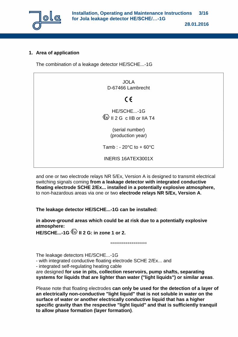
The combination of a leakage detector HE/SCHE...-1G
JOLA
D-67466 Lambrecht
HE/SCHE...-1G
II 2 G c IIB or IIA T4
(serial number)
(production year)
Tamb : - 20°C to + 60°C
INERIS 16ATEX3001X
and one or two electrode relays NR 5/Ex, Version A is designed to transmit electrical switching signals coming from a leakage detector with integrated conductive floating electrode SCHE 2/Ex... installed in a potentially explosive atmosphere, to non-hazardous areas via one or two electrode relays NR 5/Ex, Version A. The leakage detector HE/SCHE...-1G can be installed: in above-ground areas which could be at risk due to a potentially explosive atmosphere:
HE/SCHE...-1G II 2 G: in zone 1 or 2.
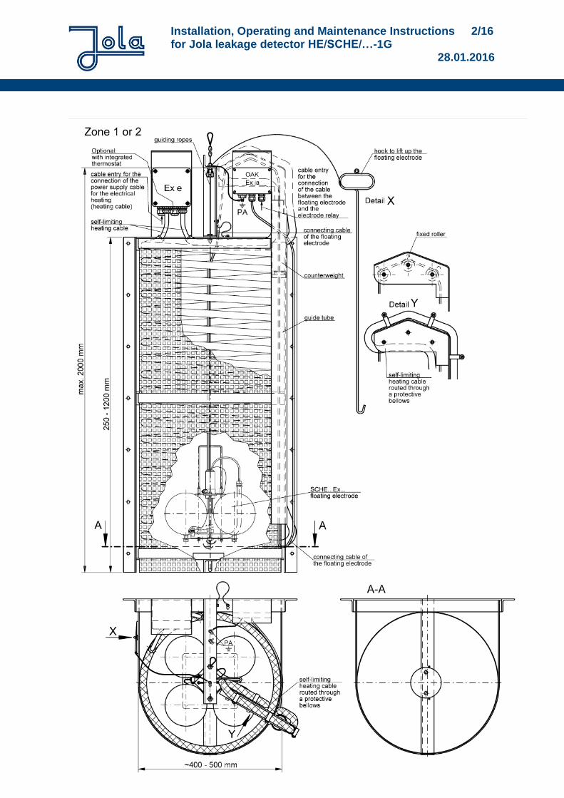
°°°°°°°°°°°°°°°°°°° The leakage detectors HE/SCHE...-1G - with integrated conductive floating electrode SCHE 2/Ex... and - integrated self-regulating heating cable are designed for use in pits, collection reservoirs, pump shafts, separating systems for liquids that are lighter than water ("light liquids") or similar areas. Please note that floating electrodes can only be used for the detection of a layer of an electrically non-conductive "light liquid" that is not soluble in water on the surface of water or another electrically conductive liquid that has a higher specific gravity than the respective "light liquid" and that is sufficiently tranquil to allow phase formation (layer formation).
Installation, Operating and Maintenance Instructions 4/16 for Jola leakage detector HE/SCHE/…-1G 28.01.2016
The precondition for the proper functioning of the floating electrodes is the possibility of clear separation between the heavier, electrically conductive liquid and the lighter, electrically non-conductive liquid to be detected in the application locations such as pits, collection reservoirs, pump shafts, separating systems or similar locations. In analogy with DIN 1999-100, DIN EN 858-1 and DIN EN 858-2 (separators for "light liquids"), separation is proven in the case of "light liquids" that are not soluble in water and are insaponifiable, such as benzines, diesel and fuel oils, and other oils of mineral origin with specific gravities up to max. 0.95. The functionability of the floating electrodes is therefore assured when used in self-contained monitoring areas without drainage (pits, collection reservoirs, pump shafts) and in separating systems in accordance with DIN 1999-100, DIN EN 858-1 and DIN EN 858-2 for the specified media. Application tests have shown that an alarm is emitted when non-conductive liquids have formed in a layer of between approx. 3 mm and 10 mm on the conductive heavy liquid to be monitored (e.g. water). Before using the floating electrodes in any other area of application, it must first be proven that the prevailing operating conditions (such as flow ratios, potential dwell time of the "light liquid" to be detected at the application location etc.) allow the phase formation with the corresponding minimum layer height of the non-conductive "light liquid" required for accurate functioning. In case of doubt, you should consult a specialist from Jola or from a monitoring organisation (e.g. the TÜV in Germany) to ascertain the suitability of the installation environment for the use of the floating electrodes.
It is essential that both media are present in low-viscosity form to ensure proper functioning of the floating electrode. In order to impede that the heavier liquid (water) freezes with temperatures under 0°C and that the ice renders inoperative the floating electrode by
immobilizing the floating electrode and thus preventing floating of it on top of a leakage liquid following a leakage eventually occurred and giving an alarm (the tips of the electrode rods of the floating electrode are still situated in the water area – this results in an OK-signalling of the leakage detector) or
giving a false alarm because the ice has isolated the tips of the electrode rods of the floating electrode (when the the tips of the electrode rods of the floating electrode are as well situated in the ice)
the leakage detector HE/SCHE…-1G is equipped with a self-regulating heating cable which should conserve the inner part of the mounting cage ice-free so that the floating electrode can follow the liquid level upwards and downwards.
Installation, Operating and Maintenance Instructions 5/16 for Jola leakage detector HE/SCHE/…-1G 28.01.2016
Proper functioning of the floating electrodes also requires a minimum liquid level above the floor (see the technical data of the respective floating electrodes). If this minimum liquid level is not present, the tips of the electrode rods are not in the liquid – in other words, they are not electrically bridged by the electrically conductive liquid. The result is normally undesired activation of the alarm via the connected electrode relay. The SCHE 2/Ex (Variant ILS) .. is the only type equipped with an alarm bridging contact for this eventuality. All the technical parameters of the conductive floating electrodes and/or the electrode relay are listed in this brochure and/or the accompanying product descriptions. These documents also contain the corresponding installation recommendations. You must always observe and follow all the instructions relating to these parameters and installation recommendations. The units may not be used for applications outside the specified parameter range. If the product descriptions are not supplied with the products or are lost, you must always request a copy of the descriptions prior to installation, connection or start-up and ensure that they are read and observed by the suitably qualified specialist personnel. Otherwise the conductive floating electrode and/or the electrode relay(s) may not be installed, connected and started up.
2. Preconditions for safe use
Maximum parameters of the conductive floating electrode SCHE 2/Ex... which is integrated in the leakage detector HE/SCHE...-1G and which is connected to the obligatory connection box OAK/SCHE/NR/.x1MΩ which is as well integrated in the leakage detector HE/SCHE...-1G
Electrode type
Type designation Li Ci
Floating electrode
SCHE 2/Ex...
0 + 1µH per metre connecting
cable
0 + 200 pF per metre
connecting cable
Floating electrode
SCHE 2/Ex (Variant 3 tiges)...
Floating electrode
SCHE 2/Ex (Variant ILS)...
Special requirements/conditions for the safe use of the conductive floating electrode SCHE 2/Ex... which is integrated in the leakage detector HE/SCHE...-1G and which is connected to the obligatory connection box OAK/SCHE/NR/.x1MΩ which is as well integrated in the leakage detector HE/SCHE...-1G Power supply to the conductive floating electrode SCHE 2/Ex... connected to the obligatory connection box OAK/SCHE/NR/.x1MΩ must be via a voltage source which is approved for use in potentially explosive
Installation, Operating and Maintenance Instructions 6/16 for Jola leakage detector HE/SCHE/…-1G 28.01.2016
atmospheres in explosion groups IIB or IIA with an output circuit which is approved as intrinsically safe. The maximum output parameters of this voltage source must not exceed the following values: Ui = 42 V; Ii = 0.1 A
Maximum parameters of the electrode relay NR 5/Ex, Version A Rated supply voltages (terminals J15, J16): U = AC 24 V, AC 110 V, AC 115 V, AC 230 V or AC 240 V Maximum electrical parameters of the electrical circuit connected to terminals J9, J10 and J11: Umax. = 250 V; Imax. = 4 A, but max. P = 100 VA Maximum electrical parameters at output terminals J1 and J7: Uo = 11.5 V; Io = 11.6 mA, but max. Po = 64 mW
Special requirements/conditions for the safe use of the electrode relay NR 5/Ex, Version A The maximum parameters of the external circuits that may be connected to terminals J1 and J7 are as follows:
For explosion group IIB For explosion group IIA
Co(L=0) = 11.1 µF Lo(C=0) = 672 mH
or Lo/Ro = 707 µH/Ohm
Co(L=0) = 45 µF Lo(C=0) = 972 mH
or Lo/Ro = 1.05 mH/Ohm
Special requirements/conditions for the safe use of the self-regulating heating cable Rated supply voltage: U = AC 230 V
Fuse provided by the customer: The self-regulating heating cable has to be connected to an AC 10 A fuse of type C characteristics provided by the customer. The connection has to be carried out by a qualified electrician of the customer outside of potentially explosive zones.
Installation, Operating and Maintenance Instructions 7/16 for Jola leakage detector HE/SCHE/…-1G 28.01.2016
3. Additional conditions for safe operation
Before using the leakage detector HE/SCHE...-1G, you must ensure that the materials used are sufficiently chemically and mechanically resistant to the liquids to be monitored and all other external influences. In case of doubt, consult a suitably trained expert prior to use. Do not use the product before these questions have been fully clarified.
The leakage detector HE/SCHE...-1G has to be used under atmospheric conditions only.
The ambient temperature of the leakage detector HE/SCHE...-1G must not fall below or exceed the following values:
Min. - 20°C and max. + 60°C.
4. Installation, connection, start-up and maintenance, general regulations
Installation, connection, start-up and maintenance of the leakage detector HE/SCHE...-1G and the electrode relay(s) may only be performed by suitably qualified specialist personnel in line with all the information material and documentation supplied with the units and following all instructions contained therein.
The qualified specialist personnel must ensure that they are familiar with all valid standards, regulations, local requirements and specific conditions, in particular the standards, regulations, local requirements and specific conditions relating to explosion protection – and must proceed accordingly.
In potentially explosive atmospheres with gas hazards the entire installation set-up of the leakage detector HE/SCHE...-1G and the electrode relay(s) NR 5/Ex, Version A must always comply with the standard EN 60 079-14 resp. the replacing standard. You must always read – and adhere to the instructions outlined in - the yellow DIN A 5 leaflet "User information/Instructions for use with mounting, operating and maintenance instructions for the product...". If the leaflet is not supplied with the product or is lost, you must always request a replacement leaflet from Jola.
5. Adjustment of the floating electrode SCHE 2/Ex… The floating electrode SCHE 2/Ex... normally floats on an electrically conductive liquid – on water, for example. The height of the rod electrode integrated in the floating electrode is set to ensure that the two electrode rod tips (model SCHE 2/Ex (Variant 3 tiges) ..:, the electrode rod tip of the upper electrode rod and the electrode rod of the earth electrode E0) are permanently under water if the surface of the water is tranquil. Depending on the degree of movement of the surface of the liquid, the position of the rod electrode must be set lower to a greater or lesser degree.
Installation, Operating and Maintenance Instructions 8/16 for Jola leakage detector HE/SCHE/…-1G 28.01.2016
The position of the rod electrode is adjusted by loosening the fastening screw(s) and pushing the rod electrode shaft up or down in the corresponding guide. When adjusting the rod electrode, its position should be optimised in such a way that the two electrode rod tips (model SCHE 2/Ex (Variant 3 tiges) ..: the electrode rod tip of the top electrode rod) is permanently but only just under water – so that if an electrically non-conductive liquid (e.g. fuel oil) forms on top of the electrically conductive liquid (e.g. water), a thin layer of the electrically non-conductive liquid suffices to lift the electrode rod tips out of the electrically conductive water phase up into the electrically non-conductive fuel oil phase, thereby interrupting the control current from the electrode relay at the rod electrode and activating the alarm.
Installation, Operating and Maintenance Instructions 9/16 for Jola leakage detector HE/SCHE/…-1G 28.01.2016
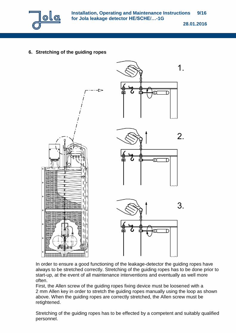
6. Stretching of the guiding ropes
In order to ensure a good functioning of the leakage-detector the guiding ropes have always to be stretched correctly. Stretching of the guiding ropes has to be done prior to start-up, at the event of all maintenance interventions and eventually as well more often. First, the Allen screw of the guiding ropes fixing device must be loosened with a 2 mm Allen key in order to stretch the guiding ropes manually using the loop as shown above. When the guiding ropes are correctly stretched, the Allen screw must be retightened. Stretching of the guiding ropes has to be effected by a competent and suitably qualified personnel.
Installation, Operating and Maintenance Instructions 10/16 for Jola leakage detector HE/SCHE/…-1G 28.01.2016
7. Installation of the electrode relay NR 5/Ex, Version A The electrode relay NR 5/Ex, Version A must be installed by qualified specialist personnel. The Installation, Operating and Maintenance Instructions for the Jola electrode relay NR 5/Ex have to be respected in all points. The NR 5/Ex, Version A electrode relay is fitted with a response sensitivity of approx. 30 kΩ (approx. 33 μS) as a standard. For applications during long lasting rainfalls which cause a decrease of conductivity, this response sensitivity might not be sufficient. In this case, the NR 5/Ex, Version A electrode relay can be fitted with a higher response sensitivity of approx. 200 kΩ (ca. 5 μS). If this is the case, it is absolutely necessary to refer to the reduced maximum length of cable (see table on page 12/15).
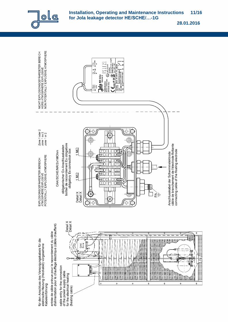
8. Connection in the form of an intrinsically safe system The intrinsically safe system composed of the floating electrode SCHE 2/Ex... with 2 electrode rods, the obligatory connection box OAK/SCHE/NR/2x1MΩ and one electrode relay NR 5/Ex, Version A must be installed and connected according to the connection diagram below. The installation personnel has to control that the 2 resistors of 1 MOhm each are present in the obligatory connection box OAK/SCHE/NR/2x1MΩ and correctly connected as shown on the connection diagram below. The intrinsically safe system composed of the floating electrode SCHE 2/Ex... with 3 electrode rods, the obligatory connection box OAK/SCHE/NR/3x1MΩ and the two electrode relays NR 5/Ex, Version A must be installed and connected analogously to the connection diagram below. The installation personnel has to control that the 3 resistors of 1 MOhm each are present in the obligatory connection box OAK/SCHE/NR/3x1MΩ and correctly connected analogously to the connection diagram below.
Installation, Operating and Maintenance Instructions 11/16 for Jola leakage detector HE/SCHE/…-1G 28.01.2016
Installation, Operating and Maintenance Instructions 12/16 for Jola leakage detector HE/SCHE/…-1G 28.01.2016
Always observe the following when connecting the unit:
Potential equalisation To avoid the danger coming from the static electricity, potential equalisation is necessary with the leakage detector HE/SCHE...-1G with integrated conductive floating electrode SCHE 2/Ex... and integrated self-regulating heating cable. The potential equalisation terminal of the leakage detector HE/SCHE...-1G must be connected to the potential equalisation system. Connection to the potential equalization system is essential for safe operation and must never be neglected. In potentially explosive atmospheres with gas hazards, the entire installation set-up of the leakage detector HE/SCHE...-1G and the electrode relay(s) NR 5/Ex, Version A must always comply with the standard EN 60 079-14 resp. the replacing standard.
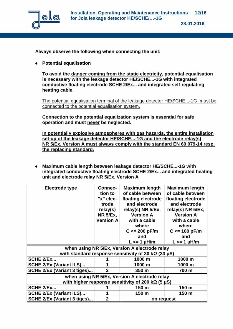
Maximum cable length between leakage detector HE/SCHE...-1G with integrated conductive floating electrode SCHE 2/Ex... and integrated heating unit and electrode relay NR 5/Ex, Version A
Electrode type Connec-tion to
"x" elec-trode
relay(s) NR 5/Ex,
Version A
Maximum length of cable between floating electrode
and electrode relay(s) NR 5/Ex,
Version A with a cable
where C <= 200 pF/m
and L <= 1 µH/m
Maximum length of cable between floating electrode
and electrode relay(s) NR 5/Ex,
Version A with a cable
where C <= 100 pF/m
and L <= 1 µH/m
when using NR 5/Ex, Version A electrode relay with standard response sensitivity of 30 kΩ (33 μS)
SCHE 2/Ex... 1 1000 m 1000 m
SCHE 2/Ex (Variant ILS)... 1 1000 m 1000 m
SCHE 2/Ex (Variant 3 tiges)... 2 350 m 700 m
when using NR 5/Ex, Version A electrode relay with higher response sensitivity of 200 kΩ (5 μS)
SCHE 2/Ex... 1 150 m 150 m
SCHE 2/Ex (Variant ILS)... 1 150 m 150 m
SCHE 2/Ex (Variant 3 tiges)... 2 on request
Installation, Operating and Maintenance Instructions 13/16 for Jola leakage detector HE/SCHE/…-1G 28.01.2016
Connecting cable for the intrinsically safe circuit Connection of the obligatory connection box OAK/SCHE/NR/3x1MΩ to one or two electrode relays NR 5 /Ex, Version A has to be realized by a connecting cable with as many conductors as needed. The connecting cable must possess a dielectric strength of at least AC 500 V test voltage. Each conductor must have a cross section greater than or equal to 0.017 mm² in order to obtain the conformity to table 2 of the standard EN 60070-11 : 2012 for a classification T4 and a current of max. 0.1 A.
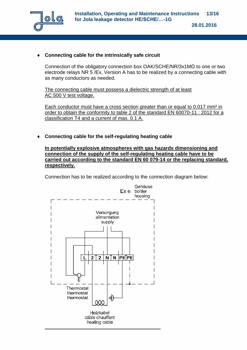
Connecting cable for the self-regulating heating cable
In potentially explosive atmospheres with gas hazards dimensioning and connection of the supply of the self-regulating heating cable have to be carried out according to the standard EN 60 079-14 or the replacing standard, respectively. Connection has to be realized according to the connection diagram below:
Installation, Operating and Maintenance Instructions 14/16 for Jola leakage detector HE/SCHE/…-1G 28.01.2016
9. Start-up
Prior to start-up, you must re-check the mounting position, the mechanical fastening and the electrical connection of the units. In particular, you must check once again that the conductive floating electrode is also connected to the corresponding, admissible intrinsically safe circuit(s). In addition, you must also check and verify that there is no possibility whatsoever of hazardous conditions occurring due to non-adherence to any of the relevant instructions, standards or official regulations. Only then may the unit in question be started up electrically. You must then perform the first maintenance routine.
10. Response in the event of an alarm After every alarm, the the leakage detector HE/SCHE...-1G with integrated conductive floating electrode SCHE 2/Ex... and integrated self-regulating heating cable and the operating area must be cleaned thoroughly. If there are signs of mechanical or chemical aggression on the floating electrode, the cable or the integrated heating unit, these must be replaced.
11. Maintenance
The the leakage detector HE/SCHE...-1G with integrated conductive floating electrode SCHE 2/Ex... and integrated self-regulating heating cable and the electrode relay(s) must be serviced at regular intervals by qualified specialist personnel. The intervals depend on the risk of soiling to the leakage detector HE/SCHE...-1G and its environment.
The unit must, however, be serviced directly after start-up.
To rule out any risks, however, the leakage detector HE/SCHE...-1G with integrated conductive floating electrode SCHE 2/Ex... and integrated self-regulating heating cable and the electrode relay(s) must be sight-checked and function-tested by qualified specialist personnel at least once a year.
Where risks cannot be ruled out, you should adhere to an inspection frequency suited to the application in question and laid down in consultation with the relevant supervisory authorities.
If the leakage detector HE/SCHE...-1G with integrated conductive floating electrode SCHE 2/Ex... and integrated self-regulating heating cable and the electrode relay(s) are installed as safety elements within a system, they must always be inspected and checked at intervals to be agreed with the local supervisory authorities.
Prior to all maintenance work, the qualified specialist personnel must inform themselves of all valid standards, regulations, local guidelines and special conditions, in particular standards, regulations, local guidelines and special conditions concerning explosion protection and proceed accordingly.
Installation, Operating and Maintenance Instructions 15/16 for Jola leakage detector HE/SCHE/…-1G 28.01.2016
Maintenance work should include the following:
The following is valid for all maintenance interventions concerning the floating electrode: It is not allowed to lift the floating electrode by its cable, because such an action could damage the cable connection inside the electrode head. You must rather use the hook which is attached to the mounting frame of the leakage detector and which can be removed to lift the floating electrode by the its handle-shaped holder. Care must be taken hereby not to damage the potential equalizing cable. After having lifted the floating electrode up to the upper crossbar of the mounting frame of the leakage detector, the floating electrode can be suspended in the round hook by the its handle-shaped holder in order to make any maintenance easier.
Cleaning of the leakage detector HE/SCHE...-1G with integrated conductive floating electrode SCHE 2/Ex... and integrated self-regulating heating cable and the surrounding area.
Sight check of the leakage detector HE/SCHE...-1G with integrated conductive floating electrode SCHE 2/Ex... and integrated self-regulating heating cable to ensure clean, flawless condition.
Sight check of the 4 guide pieces made of plastic (integrated in the floating electrode) for the 2 stainless steel guiding ropes. If traces of a heavy use are visible, the leakage detector has to be returned to the manufacturer Jola in order to replace these guide pieces. As an alternative, 4 new guide pieces made of plastic may be purchased from Jola in order to replace the old-ones by a competent and suitably qualified repair personnel.
Function check of the floating electrode as follows: All types with the exception of type SCHE 2/Ex (Variant ILS)..: Lift the floating electrode as described above. Then lift the electrode rod tips of the rod electrode mounted on the floating electrode out of the water phase. An alarm must then be emitted. Type SCHE 2/Ex (Variant ILS)..: Lift the floating electrode as described above. Then lift the electrode rod tips of the rod electrode mounted on the floating electrode out of the water phase without activating the alarm bridging contact via the activation arm (the activation arm must be freely suspended!). An alarm must then be emitted. Then test the alarm bridging contact by lifting and lowering the activation arm. During the test, the electrode rod tips may not be electrically bridged by the water. No alarm should be given when the activation arm is raised. An alarm must be emitted when the activation arm is lowered.
Installation, Operating and Maintenance Instructions 16/16 for Jola leakage detector HE/SCHE/…-1G 28.01.2016
Testing the cable break monitoring feature: Ensure that the electrode rod tips of the rod electrode are bridged by the water. Then disconnect an electrode cable (two cables with model SCHE 2/Ex (Variante 3 tiges)) in the junction box nearest the floating electrode – or, where the electrode cable is not routed through a junction box, on the respective electrode relay. Proper functioning of the cable break monitoring feature is signalled by the fact that the assigned electrode relay reverts to alarm status. The switching status caused by the cable break corresponds to the status causing an alarm due to an electrically non-conductive liquid.
12. Repair All alterations and repairs to the leakage detector HE/SCHE...-1G and/or the electrode relay(s) NR 5/Ex, Version A must be performed in the manufacturer's facility. Under no circumstances may other individuals or companies perform unauthorised alterations or repairs. If only the 4 guide pieces for the 2 stainless steel guiding ropes have to be replaced, 4 new guide pieces made of plastic may (as an alternative to send the leakage detector back to Jola) be purchased from Jola in order to replace the old-ones by a competent and suitably qualified repair personnel.
Installation, Operating and Maintenance 1/6 Instructions for Jola Electrode Relay NR 5/Ex 21.11.2013
Installation, Operating and Maintenance Instructions for
Jola Electrode Relay
NR 5/Ex I (M1) / II (1) GD [Ex ia Ma] I
[Ex ia Ga] IIC [Ex ia Da] IIIC
These Installation, Operating and Maintenance Instructions must always be handed over to the
fitter/operator/service personnel of our products together with all other user
documentation and information! They should be stored in a safe place together
with all other user documentation and information so they can be consulted again when necessary at
any time!
Jola Spezialschalter GmbH & Co. KG Klostergartenstr. 11 • 67466 Lambrecht (Germany)
Tel. +49 6325 188-01 • Fax +49 6325 6396 [email protected] • www.jola-info.de
Installation, Operating and Maintenance 2/6 Instructions for Jola Electrode Relay NR 5/Ex 21.11.2013
1. Area of application
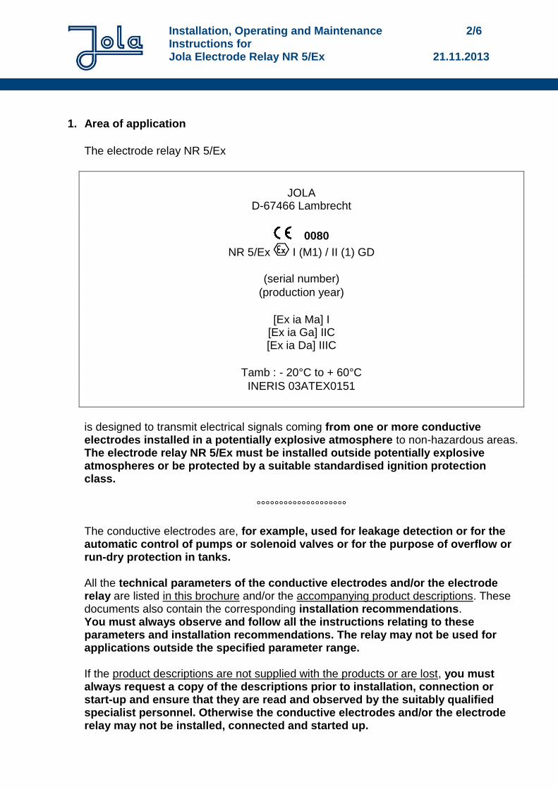
The electrode relay NR 5/Ex
JOLA D-67466 Lambrecht
0080
NR 5/Ex I (M1) / II (1) GD
(serial number)
(production year)
[Ex ia Ma] I [Ex ia Ga] IIC [Ex ia Da] IIIC
Tamb : - 20°C to + 60°C
INERIS 03ATEX0151
is designed to transmit electrical signals coming from one or more conductive electrodes installed in a potentially explosive atmosphere to non-hazardous areas. The electrode relay NR 5/Ex must be installed outside potentially explosive atmospheres or be protected by a suitable standardised ignition protection class.
°°°°°°°°°°°°°°°°°°°° The conductive electrodes are, for example, used for leakage detection or for the automatic control of pumps or solenoid valves or for the purpose of overflow or run-dry protection in tanks. All the technical parameters of the conductive electrodes and/or the electrode relay are listed in this brochure and/or the accompanying product descriptions. These documents also contain the corresponding installation recommendations. You must always observe and follow all the instructions relating to these parameters and installation recommendations. The relay may not be used for applications outside the specified parameter range. If the product descriptions are not supplied with the products or are lost, you must always request a copy of the descriptions prior to installation, connection or start-up and ensure that they are read and observed by the suitably qualified specialist personnel. Otherwise the conductive electrodes and/or the electrode relay may not be installed, connected and started up.
Installation, Operating and Maintenance 3/6 Instructions for Jola Electrode Relay NR 5/Ex 21.11.2013
2. Preconditions for safe use
Maximum parameters of the conductive electrodes The maximum parameters of the conductive electrodes are listed in the corresponding product documentation.
Special requirements/conditions for the safe use of the conductive electrodes The special requirements/conditions for the safe use of the conductive electrodes are listed in the corresponding product documentation.
Maximum parameters of the electrode relay NR 5/Ex Rated supply voltages (terminals J15, J16): U = AC 24 V, AC 110 V, AC 115 V, AC 230 V or AC 240 V Maximum electrical parameters of the electrical circuit connected to terminals J9, J10 and J11: Umax. = 250 V; Imax. = 4A, but max. P = 100 VA Maximum electrical parameters at output terminals J6 and J7: Uo = 22 V; Io = 6 mA, but max. Po = 31.8 mW Maximum electrical parameters at output terminals (J1, J6) or (J1, J7): Uo = 11.5 V; Io = 11.6 mA, but max. Po = 64 mW
Special requirements/conditions for the safe use of the electrode relay NR 5/Ex The electrode relay NR 5/Ex must be installed outside potentially explosive atmospheres or be protected by a suitable standardised ignition protection class. The electrical circuits connected to terminals J6 and J7 must be approved for use - in above-ground areas which could be at risk due to a potentially explosive atmosphere caused by gases (groups IIC, IIB or IIA) or - in underground areas in mines as well as in above-ground areas of mines which could be at risk due to firedamp and/or flammable dusts (group I) or - in above-ground areas which could be at risk due to a potentially explosive atmosphere caused by dusts and their suitability in terms of intrinsic safety must be ensured.
Installation, Operating and Maintenance 4/6 Instructions for Jola Electrode Relay NR 5/Ex 21.11.2013
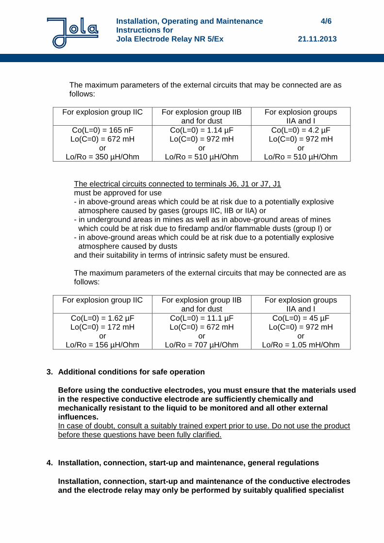
The maximum parameters of the external circuits that may be connected are as follows:
For explosion group IIC For explosion group IIB and for dust
For explosion groups IIA and I
Co(L=0) = 165 nF Lo(C=0) = 672 mH
or Lo/Ro = 350 µH/Ohm
Co(L=0) = 1.14 µF Lo(C=0) = 972 mH
or Lo/Ro = 510 µH/Ohm
Co(L=0) = 4.2 µF Lo(C=0) = 972 mH
or Lo/Ro = 510 µH/Ohm
The electrical circuits connected to terminals J6, J1 or J7, J1 must be approved for use - in above-ground areas which could be at risk due to a potentially explosive atmosphere caused by gases (groups IIC, IIB or IIA) or - in underground areas in mines as well as in above-ground areas of mines which could be at risk due to firedamp and/or flammable dusts (group I) or - in above-ground areas which could be at risk due to a potentially explosive atmosphere caused by dusts and their suitability in terms of intrinsic safety must be ensured. The maximum parameters of the external circuits that may be connected are as follows:
For explosion group IIC For explosion group IIB and for dust
For explosion groups IIA and I
Co(L=0) = 1.62 µF Lo(C=0) = 172 mH
or Lo/Ro = 156 µH/Ohm
Co(L=0) = 11.1 µF Lo(C=0) = 672 mH
or Lo/Ro = 707 µH/Ohm
Co(L=0) = 45 µF Lo(C=0) = 972 mH
or Lo/Ro = 1.05 mH/Ohm
3. Additional conditions for safe operation
Before using the conductive electrodes, you must ensure that the materials used in the respective conductive electrode are sufficiently chemically and mechanically resistant to the liquid to be monitored and all other external influences. In case of doubt, consult a suitably trained expert prior to use. Do not use the product before these questions have been fully clarified.
4. Installation, connection, start-up and maintenance, general regulations
Installation, connection, start-up and maintenance of the conductive electrodes and the electrode relay may only be performed by suitably qualified specialist
Installation, Operating and Maintenance 5/6 Instructions for Jola Electrode Relay NR 5/Ex 21.11.2013
personnel in line with all the information material and documentation supplied with the units and following all instructions contained therein.
The qualified specialist personnel must ensure that they are familiar with all valid standards, regulations, local requirements and specific conditions, in particular the standards, regulations, local requirements and specific conditions relating to explosion protection – and must proceed accordingly.
You must always read – and adhere to the instructions outlined in - the yellow DIN A 5 leaflet "User information/Instructions for use with mounting, operating and maintenance instructions for the product...". If the leaflet is not supplied with the product or is lost, you must always request a replacement leaflet from Jola.
5. Installation and connection of the electrode relay NR 5/Ex
The electrode relay NR 5/Ex must be installed outside potentially explosive atmospheres or be protected by a suitable standardized ignition protection class. The entire installation set-up must always comply with the standard EN 60 079-14 resp. the replacing standard.
The unit is designed exclusively for installation in a switch cabinet or in a suitable protective housing and may therefore only be installed in these locations. It is only suitable for use in clean environments.
6. Start-up
Prior to start-up, you must re-check the mounting position of all the units, the mechanical fastening and the electrical connection. In particular, you must check once again that the electrodes are connected to the corresponding, admissible intrinsically safe circuit(s). In addition, you must also check and verify that there is no possibility whatsoever of hazardous conditions occurring due to non-adherence to any of the relevant instructions, standards or official regulations. Only then may the unit in question be started up electrically.
7. Maintenance
The maintenance intervals are listed in the product documentation for the conductive electrodes. To rule out any risks, however, the conductive electrodes and electrode relay must be sight-checked and function-tested by qualified specialist personnel at least once a year.
Installation, Operating and Maintenance 6/6 Instructions for Jola Electrode Relay NR 5/Ex 21.11.2013
Where risks cannot be ruled out, you should adhere to an inspection frequency suited to the application in question and laid down in consultation with the relevant supervisory authorities.
If the conductive electrode(s) and electrode relay are installed as safety elements within a system, they must always be inspected and checked at intervals to be agreed with the local supervisory authorities.
Prior to all maintenance work, the qualified specialist personnel must inform themselves of all valid standards, regulations, local guidelines and special conditions, in particular standards, regulations, local guidelines and special conditions concerning explosion protection and proceed accordingly.
8. Repair All alterations and repairs to the conductive electrode(s) and/or the electrode relay NR 5/Ex must be performed in the manufacturer's facility. Under no circumstances may other individuals or companies perform unauthorised alterations or repairs.