operating instructions english vector 1800 & vector · pdf file62--60558--03 3 operating...
TRANSCRIPT

362--60558--03
OPERATING INSTRUCTIONS English
VECTOR 1800 & VECTOR 1800 Mt˚
1. INTRODUCTION
This guide has been prepared for the operator of Carrier Transicold refrigeration units. It contains basicinstructions for the daily operation of the refrigeration unit as well as safety information, troubleshooting tips,and other information that will help you to deliver the load in the best possible condition.
Please take the time to read the information contained in this booklet and refer to it whenever you have aquestion about the operation of your Carrier Transicold unit. This manual refers to the standard model. Someoptions may not appear in it, and in such cases you are requested to consult our Technical Services.
Your refrigeration unit has been engineered to provide long, trouble--free performance when it is properlyoperated and maintained. The checks outlined in this guide will help to minimize on the road problems. Inaddition, a comprehensive maintenance programwill help to insure that the unit continues to operate reliably.Such a maintenance program will also help to control operating costs, increase the unit’s working life, andimprove performance.
When having your unit serviced, be sure to specify genuine Carrier Transicold replacement parts for thehighest quality and best reliability.
At Carrier Transicold, we are continually working to improve the products that we build for our customers. Asa result, specifications may change without notice.
CONTENTS
1. Introduction 3. . . . . . . . . . . . . . . . . . . . . . . . . . . . . . . . . . . . . . . . . . . . . .
2. Identification 5. . . . . . . . . . . . . . . . . . . . . . . . . . . . . . . . . . . . . . . . . . . . . .
2.1. Nameplate 5. . . . . . . . . . . . . . . . . . . . . . . . . . . . . . . . . . . . . . . . . . . . . . .
2.2. Noise level sticker (fixed if available) 5. . . . . . . . . . . . . . . . . . . . . . . . .
3. Warnings and precautions 5. . . . . . . . . . . . . . . . . . . . . . . . . . . . . . . . . .
3.1. Warning stickers maintenance 9. . . . . . . . . . . . . . . . . . . . . . . . . . . . . .
4. Product loading 9. . . . . . . . . . . . . . . . . . . . . . . . . . . . . . . . . . . . . . . . . . .
5. Recommended transport temperatures 11. . . . . . . . . . . . . . . . . . . . . .
6. Quick glance on the display board 11. . . . . . . . . . . . . . . . . . . . . . . . . .
6.1. Microprocessor LOGICOLD 11. . . . . . . . . . . . . . . . . . . . . . . . . . . . . . . .
6.2. Optional control panel 12. . . . . . . . . . . . . . . . . . . . . . . . . . . . . . . . . . . . . .
7. Pretrip inspection 12. . . . . . . . . . . . . . . . . . . . . . . . . . . . . . . . . . . . . . . . .
8. Operation 13. . . . . . . . . . . . . . . . . . . . . . . . . . . . . . . . . . . . . . . . . . . . . . . .
8.1. Starting the unit -- ROAD operation 13. . . . . . . . . . . . . . . . . . . . . . . . . . .
8.2. Starting the unit -- STANDBY operation 13. . . . . . . . . . . . . . . . . . . . . . .8.2.1. Standby operation guidelines 13. . . . . . . . . . . . . . . . . . . . . . . . . . . . .
8.3. Unit shut--down 14. . . . . . . . . . . . . . . . . . . . . . . . . . . . . . . . . . . . . . . . . . .
8.4. Manual defrost 14. . . . . . . . . . . . . . . . . . . . . . . . . . . . . . . . . . . . . . . . . . .
8.5. To change setpoint temperature 15. . . . . . . . . . . . . . . . . . . . . . . . . . . . .
4 62--60558--03
8.6. Start--Stop operation 15. . . . . . . . . . . . . . . . . . . . . . . . . . . . . . . . . . . . . . .8.6.1. Start/Stop system -- Road operation 15. . . . . . . . . . . . . . . . . . . . . . . .8.6.2. Start/Stop system -- Standby operation 16. . . . . . . . . . . . . . . . . . . . .
8.7. Continuous run operation 16. . . . . . . . . . . . . . . . . . . . . . . . . . . . . . . . . . .
8.8. Pretrip 17. . . . . . . . . . . . . . . . . . . . . . . . . . . . . . . . . . . . . . . . . . . . . . . . . .
8.9. Trip start 17. . . . . . . . . . . . . . . . . . . . . . . . . . . . . . . . . . . . . . . . . . . . . . . . .
8.10. To display unit data 17. . . . . . . . . . . . . . . . . . . . . . . . . . . . . . . . . . . . . . . .
8.11. To change a function 19. . . . . . . . . . . . . . . . . . . . . . . . . . . . . . . . . . . . . .
8.12. Operation with auxiliary control panel (option for V1800 Mt_ only) 21.8.12.1. Change the setpoint 21. . . . . . . . . . . . . . . . . . . . . . . . . . . . . . . . . . . . .8.12.2. To set pre--set setpoint 21. . . . . . . . . . . . . . . . . . . . . . . . . . . . . . . . . . .8.12.3. To remove pre--set setpoint 22. . . . . . . . . . . . . . . . . . . . . . . . . . . . . . .8.12.4. To lock and unlock the control panel 22. . . . . . . . . . . . . . . . . . . . . . .
9. Problems 23. . . . . . . . . . . . . . . . . . . . . . . . . . . . . . . . . . . . . . . . . . . . . . . . .9.1. Fuses location 23. . . . . . . . . . . . . . . . . . . . . . . . . . . . . . . . . . . . . . . . . . . .
9.2. Fault alarm display and safety features 23. . . . . . . . . . . . . . . . . . . . . . .9.2.1. Alarm and default messages 23. . . . . . . . . . . . . . . . . . . . . . . . . . . . . .9.2.2. To view an alarm 24. . . . . . . . . . . . . . . . . . . . . . . . . . . . . . . . . . . . . . . .
10. Maintenance 27. . . . . . . . . . . . . . . . . . . . . . . . . . . . . . . . . . . . . . . . . . . . . .10.1. Oil change intervals 27. . . . . . . . . . . . . . . . . . . . . . . . . . . . . . . . . . . . . . .
10.2. Maintenance schedule 27. . . . . . . . . . . . . . . . . . . . . . . . . . . . . . . . . . . . .
10.3. Services description 28. . . . . . . . . . . . . . . . . . . . . . . . . . . . . . . . . . . . . . .
10.4. Recommended oil 29. . . . . . . . . . . . . . . . . . . . . . . . . . . . . . . . . . . . . . . . .
11. A.T.P. Europe Regulation extract 30. . . . . . . . . . . . . . . . . . . . . . . . . . . .12. 24h Assistance 31. . . . . . . . . . . . . . . . . . . . . . . . . . . . . . . . . . . . . . . . . . . .
562--60558--03
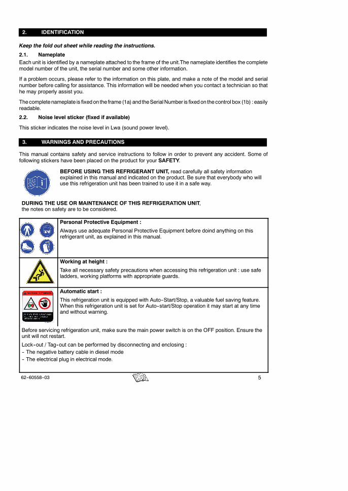
2. IDENTIFICATION
Keep the fold out sheet while reading the instructions.
2.1. NameplateEach unit is identified by a nameplate attached to the frame of the unit.The nameplate identifies the completemodel number of the unit, the serial number and some other information.
If a problem occurs, please refer to the information on this plate, and make a note of the model and serialnumber before calling for assistance. This information will be needed when you contact a technician so thathe may properly assist you.
Thecompletenameplate is fixedon the frame (1a) and theSerialNumber is fixedon thecontrol box (1b) : easilyreadable.
2.2. Noise level sticker (fixed if available)
This sticker indicates the noise level in Lwa (sound power level).
3. WARNINGS AND PRECAUTIONS
This manual contains safety and service instructions to follow in order to prevent any accident. Some offollowing stickers have been placed on the product for your SAFETY.
BEFORE USING THIS REFRIGERANT UNIT, read carefully all safety informationexplained in this manual and indicated on the product. Be sure that everybody who willuse this refrigeration unit has been trained to use it in a safe way.
DURING THE USE OR MAINTENANCE OF THIS REFRIGERATION UNIT,the notes on safety are to be considered.
Personal Protective Equipment :
Always use adequate Personal Protective Equipment before doind anything on thisrefrigerant unit, as explained in this manual.
Working at height :
Take all necessary safety precautions when accessing this refrigeration unit : use safeladders, working platforms with appropriate guards.
Automatic start :
This refrigeration unit is equipped with Auto--Start/Stop, a valuable fuel saving feature.When this refrigeration unit is set for Auto--start/Stop operation it may start at any timeand without warning.
Before servicing refrigeration unit, make sure the main power switch is on the OFF position. Ensure theunit will not restart.
Lock--out / Tag--out can be performed by disconnecting and enclosing :-- The negative battery cable in diesel mode-- The electrical plug in electrical mode.

6 62--60558--03
Belts and fans :
This refrigeration unit is equipped with Auto--start/stop, it may start at any time andwithout warning.
When the unit is running beware of belts and fans that are moving.Before servicing refrigeration unit,make sure the main power switch is on the OFF position.
Ensure the unit will not restart. Lock--out / Tag--out can be performed as described above.
When there is protective structure (fan grid or guard for example) make sure they are in place. Neverremoved them when the refrigeration unit is running.
Always keep your hands, body parts, clothes, hairs and tools far from moving parts.
Electricity :
When this refrigeration unit is running in electrical operation, some devices are poweredup especially in the electrical control box.
Before servicing refrigeration unit, make sure the main power switch is on the OFFposition. Ensure this refrigeration unit is disconnected from the local electricalnetwork.Lock--out / Tag--out can be performed as described above.
Before working in the electrical control box, it is required to control the lack of tension.
WHEN IT IS NECESSARY TO WORK IN THE ELECTRICAL CONTROL BOX UNDERTENSION, PEOPLE MUST BE QUALIFIED FOR WORKS UNDER LOW OR HIGHVOLTAGE.
Always use adequate tools and Personal Protective Equipment when working onelectrical devices : safety gloves and safety glasses.
Power generator :
Be aware of HIGH VOLTAGE (up to 700V) supplied by the generator as the unit maystart automatically. Before servicing the unit, make sure the RUN/STOP switch is in theSTOP position. Also disconnect the negative battery cable.
NEVER dis--assemble the generator : HIGH MAGNETIC FIELD INSIDE !
Pacemaker holders must stay clear of the unit while operating as the power generatorsupplies HIGH VOLTAGE AND MAGNETIC FIELD.
Engine coolant :
This refrigeration unit is equipped with a pressurised cooling system. Under normaloperating conditions, the coolant in the engine and radiator is under high pressure andvery hot.
Coolant is very slippery. It can be harmful in case of ingestion.
Never remove the cap from a hot radiator when this refrigeration unit is running orimmediately after.
If the cap must be removed, wait at least 10 minutes and then do so very slowly inorder to release the pressure without spray.
In case of leakage, immediatly clean the floor to prevent slipping.
Avoid contact with the skin and eyes. Always use Personal Protective Equipment whenhandling engine coolant : safety clothes, safety gloves and safety glasses.
762--60558--03
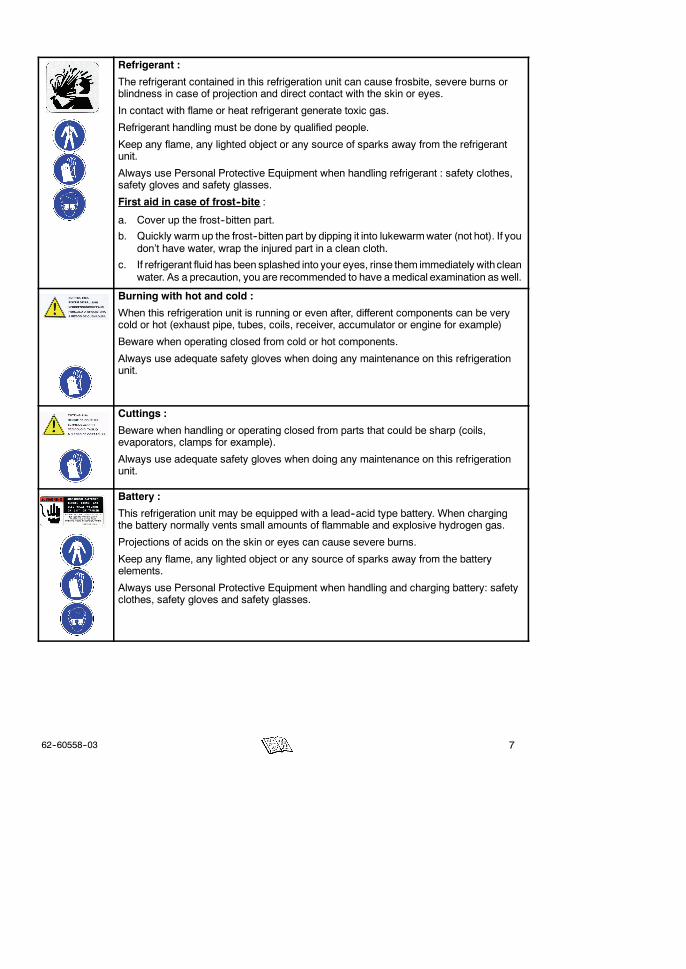
Refrigerant :
The refrigerant contained in this refrigeration unit can cause frosbite, severe burns orblindness in case of projection and direct contact with the skin or eyes.
In contact with flame or heat refrigerant generate toxic gas.
Refrigerant handling must be done by qualified people.
Keep any flame, any lighted object or any source of sparks away from the refrigerantunit.
Always use Personal Protective Equipment when handling refrigerant : safety clothes,safety gloves and safety glasses.
First aid in case of frost--bite :
a. Cover up the frost--bitten part.
b. Quickly warm up the frost--bitten part by dipping it into lukewarmwater (not hot). If youdon’t have water, wrap the injured part in a clean cloth.
c. If refrigerant fluid has been splashed into your eyes, rinse them immediately withcleanwater. As a precaution, you are recommended to have amedical examination as well.
Burning with hot and cold :
When this refrigeration unit is running or even after, different components can be verycold or hot (exhaust pipe, tubes, coils, receiver, accumulator or engine for example)
Beware when operating closed from cold or hot components.
Always use adequate safety gloves when doing any maintenance on this refrigerationunit.
Cuttings :
Beware when handling or operating closed from parts that could be sharp (coils,evaporators, clamps for example).
Always use adequate safety gloves when doing any maintenance on this refrigerationunit.
Battery :
This refrigeration unit may be equipped with a lead--acid type battery. When chargingthe battery normally vents small amounts of flammable and explosive hydrogen gas.
Projections of acids on the skin or eyes can cause severe burns.
Keep any flame, any lighted object or any source of sparks away from the batteryelements.
Always use Personal Protective Equipment when handling and charging battery: safetyclothes, safety gloves and safety glasses.
8 62--60558--03
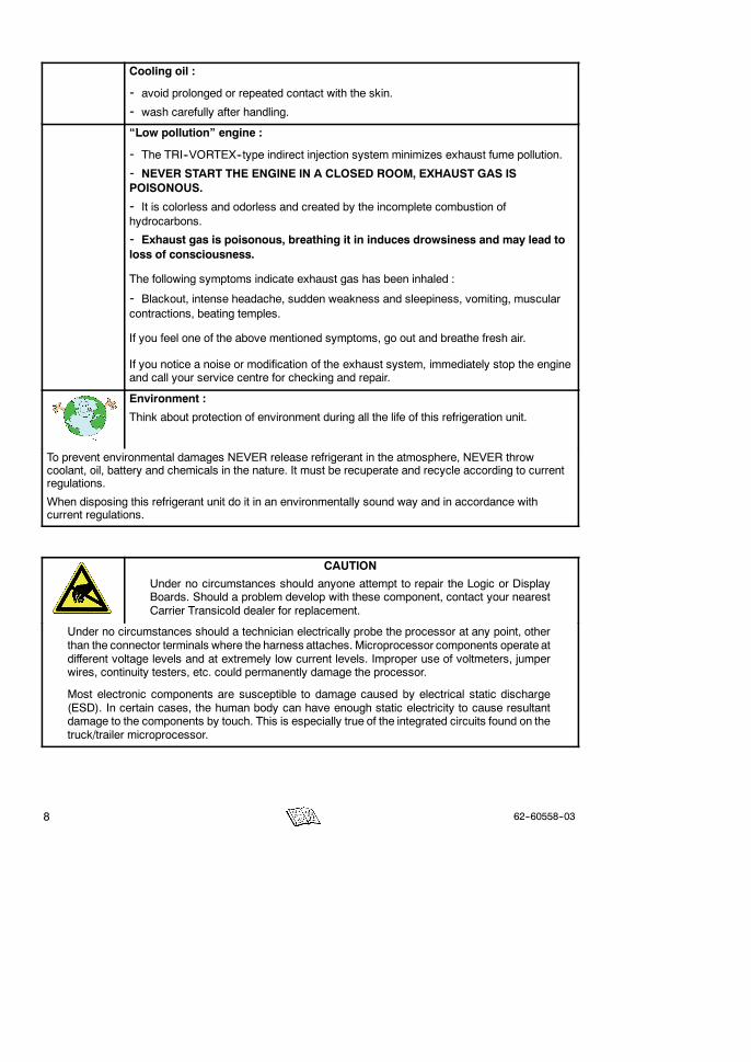
Cooling oil :
- avoid prolonged or repeated contact with the skin.- wash carefully after handling.“Low pollution” engine :
- The TRI--VORTEX--type indirect injection system minimizes exhaust fume pollution.
- NEVER START THE ENGINE IN A CLOSED ROOM, EXHAUST GAS ISPOISONOUS.
- It is colorless and odorless and created by the incomplete combustion ofhydrocarbons.
- Exhaust gas is poisonous, breathing it in induces drowsiness and may lead toloss of consciousness.
The following symptoms indicate exhaust gas has been inhaled :
- Blackout, intense headache, sudden weakness and sleepiness, vomiting, muscularcontractions, beating temples.
If you feel one of the above mentioned symptoms, go out and breathe fresh air.
If you notice a noise or modification of the exhaust system, immediately stop the engineand call your service centre for checking and repair.
Environment :
Think about protection of environment during all the life of this refrigeration unit.
To prevent environmental damages NEVER release refrigerant in the atmosphere, NEVER throwcoolant, oil, battery and chemicals in the nature. It must be recuperate and recycle according to currentregulations.
When disposing this refrigerant unit do it in an environmentally sound way and in accordance withcurrent regulations.
CAUTION
Under no circumstances should anyone attempt to repair the Logic or DisplayBoards. Should a problem develop with these component, contact your nearestCarrier Transicold dealer for replacement.
Under no circumstances should a technician electrically probe the processor at any point, otherthan the connector terminals where the harness attaches. Microprocessor components operate atdifferent voltage levels and at extremely low current levels. Improper use of voltmeters, jumperwires, continuity testers, etc. could permanently damage the processor.
Most electronic components are susceptible to damage caused by electrical static discharge(ESD). In certain cases, the human body can have enough static electricity to cause resultantdamage to the components by touch. This is especially true of the integrated circuits found on thetruck/trailer microprocessor.
962--60558--03
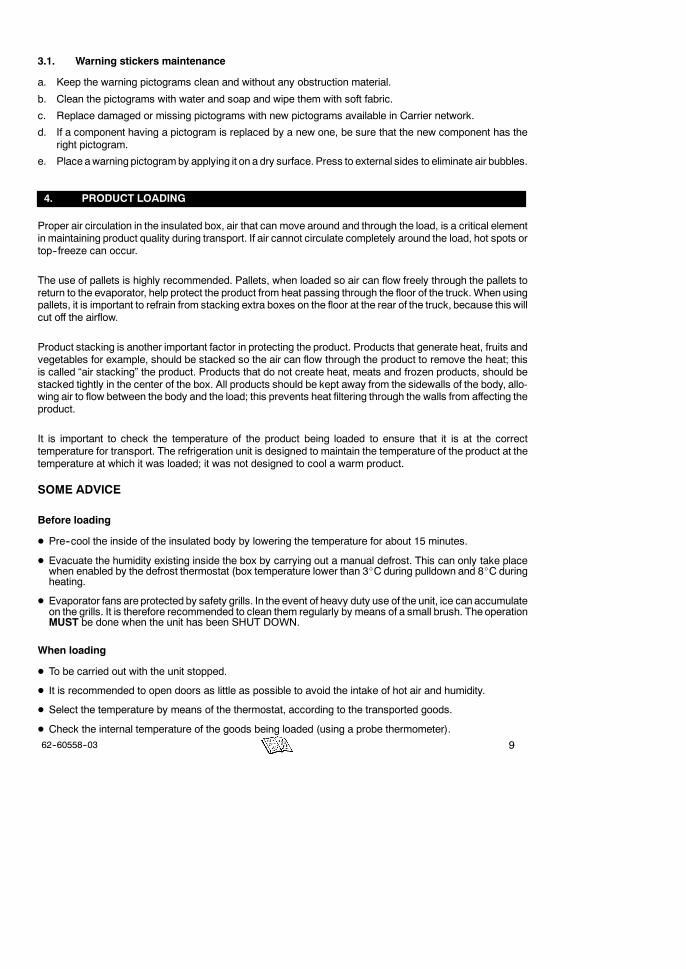
3.1. Warning stickers maintenance
a. Keep the warning pictograms clean and without any obstruction material.
b. Clean the pictograms with water and soap and wipe them with soft fabric.
c. Replace damaged or missing pictograms with new pictograms available in Carrier network.
d. If a component having a pictogram is replaced by a new one, be sure that the new component has theright pictogram.
e. Place awarning pictogramby applying it on a dry surface. Press to external sides to eliminate air bubbles.
4. PRODUCT LOADING
Proper air circulation in the insulated box, air that can move around and through the load, is a critical elementin maintaining product quality during transport. If air cannot circulate completely around the load, hot spots ortop--freeze can occur.
The use of pallets is highly recommended. Pallets, when loaded so air can flow freely through the pallets toreturn to the evaporator, help protect the product from heat passing through the floor of the truck. When usingpallets, it is important to refrain from stacking extra boxes on the floor at the rear of the truck, because this willcut off the airflow.
Product stacking is another important factor in protecting the product. Products that generate heat, fruits andvegetables for example, should be stacked so the air can flow through the product to remove the heat; thisis called “air stacking” the product. Products that do not create heat, meats and frozen products, should bestacked tightly in the center of the box. All products should be kept away from the sidewalls of the body, allo-wing air to flow between the body and the load; this prevents heat filtering through the walls from affecting theproduct.
It is important to check the temperature of the product being loaded to ensure that it is at the correcttemperature for transport. The refrigeration unit is designed to maintain the temperature of the product at thetemperature at which it was loaded; it was not designed to cool a warm product.
SOME ADVICE
Before loading
D Pre--cool the inside of the insulated body by lowering the temperature for about 15 minutes.
D Evacuate the humidity existing inside the box by carrying out a manual defrost. This can only take placewhen enabled by the defrost thermostat (box temperature lower than 3_C during pulldown and 8_C duringheating.
D Evaporator fans are protected by safety grills. In the event of heavy duty use of the unit, ice can accumulateon the grills. It is therefore recommended to clean them regularly by means of a small brush. The operationMUST be done when the unit has been SHUT DOWN.
When loading
D To be carried out with the unit stopped.
D It is recommended to open doors as little as possible to avoid the intake of hot air and humidity.
D Select the temperature by means of the thermostat, according to the transported goods.
D Check the internal temperature of the goods being loaded (using a probe thermometer).

10 62--60558--03
Load spacers
Load on pallets
D Take care not to obstruct the air intakes onthe evaporator section and the ventilationducts.
D Leave a free space of about :- 6 to 8 cm between load and frontwall,
- 20 cm between the top of the load and theroof,
- between the floor and the load (gratings,pallets).
D Do not forget to close the doors.
D Before closing the doors, check your load once more and see that nobody is shut inside the box.
OPTIONS FOR INSULATED BODIES
D Mobile partition
The mobile partition must be placed at a minimum distance from the evaporator of 1700 mm.
D Ducting of evaporator air outlet
Ventilation ducts must never be covered.
NOTE :
For stationnary utilization, we recommendto place the body in the shade.
IMPORTANT
Never leave your unit more than amonthwithout running.
1162--60558--03
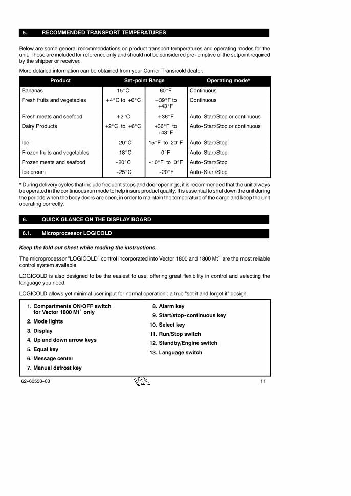
5. RECOMMENDED TRANSPORT TEMPERATURES
Below are some general recommendations on product transport temperatures and operating modes for theunit. These are included for reference only and should not be considered pre--emptive of the setpoint requiredby the shipper or receiver.
More detailed information can be obtained from your Carrier Transicold dealer.
Product Set--point Range Operating mode*
Bananas 15_C 60_F Continuous
Fresh fruits and vegetables +4_C to +6_C +39_F to+43_F
Continuous
Fresh meats and seefood +2_C +36_F Auto--Start/Stop or continuous
Dairy Products +2_C to +6_C +36_F to+43_F
Auto--Start/Stop or continuous
Ice --20_C 15_F to 20_F Auto--Start/Stop
Frozen fruits and vegetables --18_C 0_F Auto--Start/Stop
Frozen meats and seafood --20_C --10_F to 0_F Auto--Start/Stop
Ice cream --25_C --20_F Auto--Start/Stop
* During delivery cycles that include frequent stops and door openings, it is recommended that the unit alwaysbeoperated in thecontinuous runmode tohelp insureproduct quality. It is essential to shut down the unit duringthe periods when the body doors are open, in order to maintain the temperature of the cargo and keep the unitoperating correctly.
6. QUICK GLANCE ON THE DISPLAY BOARD
6.1. Microprocessor LOGICOLD
Keep the fold out sheet while reading the instructions.
The microprocessor “LOGICOLD” control incorporated into Vector 1800 and 1800 Mt˚ are the most reliablecontrol system available.
LOGICOLD is also designed to be the easiest to use, offering great flexibility in control and selecting thelanguage you need.
LOGICOLD allows yet minimal user input for normal operation : a true “set it and forget it” design.
1. Compartments ON/OFF switchfor Vector 1800 Mt˚ only
2. Mode lights
3. Display
4. Up and down arrow keys
5. Equal key
6. Message center
7. Manual defrost key
8. Alarm key
9. Start/stop--continuous key
10. Select key
11. Run/Stop switch
12. Standby/Engine switch
13. Language switch
12 62--60558--03
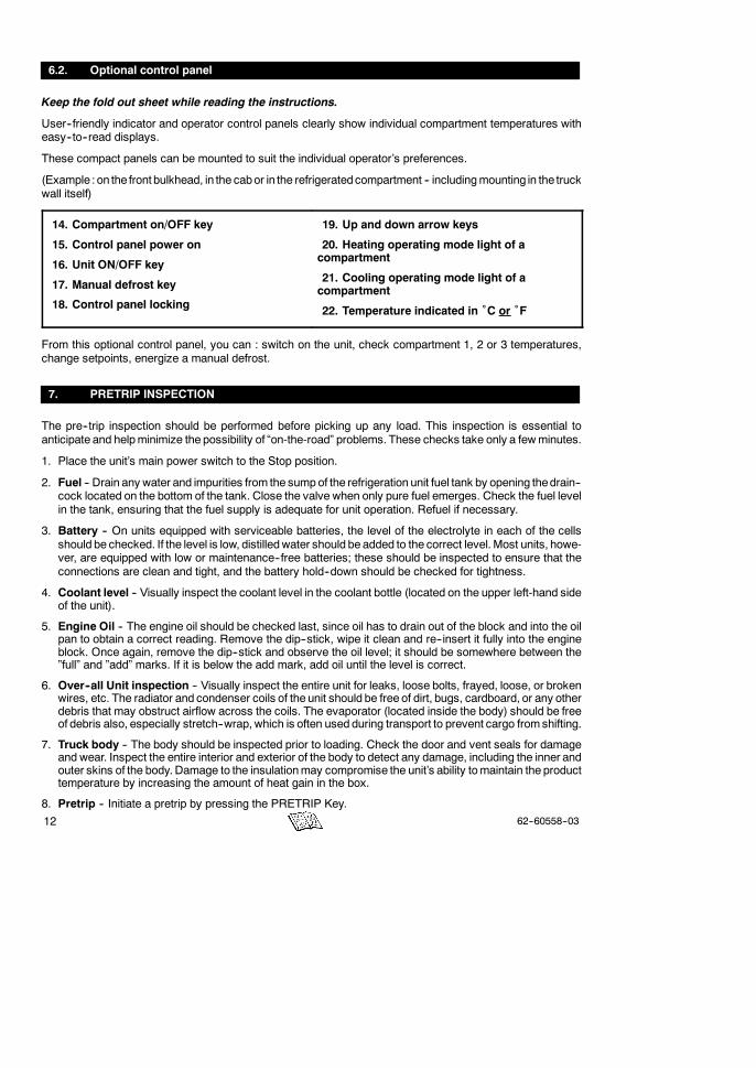
6.2. Optional control panel
Keep the fold out sheet while reading the instructions.
User--friendly indicator and operator control panels clearly show individual compartment temperatures witheasy--to--read displays.
These compact panels can be mounted to suit the individual operator’s preferences.
(Example : on the front bulkhead, in the cabor in the refrigeratedcompartment -- includingmounting in the truckwall itself)
14. Compartment on/OFF key
15. Control panel power on
16. Unit ON/OFF key
17. Manual defrost key
18. Control panel locking
19. Up and down arrow keys
20. Heating operating mode light of acompartment
21. Cooling operating mode light of acompartment
22. Temperature indicated in ˚C or ˚F
From this optional control panel, you can : switch on the unit, check compartment 1, 2 or 3 temperatures,change setpoints, energize a manual defrost.
7. PRETRIP INSPECTION
The pre--trip inspection should be performed before picking up any load. This inspection is essential toanticipate and helpminimize the possibility of “on-the-road” problems. These checks take only a fewminutes.
1. Place the unit’s main power switch to the Stop position.
2. Fuel -- Drain any water and impurities from the sumpof the refrigeration unit fuel tank by opening thedrain--cock located on the bottom of the tank. Close the valve when only pure fuel emerges. Check the fuel levelin the tank, ensuring that the fuel supply is adequate for unit operation. Refuel if necessary.
3. Battery -- On units equipped with serviceable batteries, the level of the electrolyte in each of the cellsshould be checked. If the level is low, distilledwater should be added to the correct level. Most units, howe-ver, are equipped with low or maintenance--free batteries; these should be inspected to ensure that theconnections are clean and tight, and the battery hold--down should be checked for tightness.
4. Coolant level -- Visually inspect the coolant level in the coolant bottle (located on the upper left-hand sideof the unit).
5. Engine Oil -- The engine oil should be checked last, since oil has to drain out of the block and into the oilpan to obtain a correct reading. Remove the dip--stick, wipe it clean and re--insert it fully into the engineblock. Once again, remove the dip--stick and observe the oil level; it should be somewhere between the”full” and ”add” marks. If it is below the add mark, add oil until the level is correct.
6. Over--all Unit inspection -- Visually inspect the entire unit for leaks, loose bolts, frayed, loose, or brokenwires, etc. The radiator and condenser coils of the unit should be free of dirt, bugs, cardboard, or any otherdebris that may obstruct airflow across the coils. The evaporator (located inside the body) should be freeof debris also, especially stretch--wrap, which is often used during transport to prevent cargo fromshifting.
7. Truck body -- The body should be inspected prior to loading. Check the door and vent seals for damageand wear. Inspect the entire interior and exterior of the body to detect any damage, including the inner andouter skins of the body. Damage to the insulationmay compromise the unit’s ability tomaintain the producttemperature by increasing the amount of heat gain in the box.
8. Pretrip -- Initiate a pretrip by pressing the PRETRIP Key.
1362--60558--03
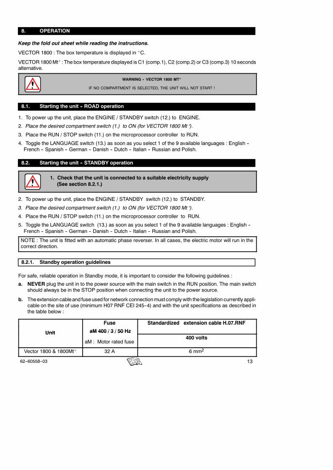
8. OPERATION
Keep the fold out sheet while reading the instructions.
VECTOR 1800 : The box temperature is displayed in _C.
VECTOR1800Mt_ : The box temperature displayed is C1 (comp.1), C2 (comp.2) or C3 (comp.3) 10 secondsalternative.
WARNING -- VECTOR 1800 MT_
IF NO COMPARTMENT IS SELECTED, THE UNIT WILL NOT START !
8.1. Starting the unit -- ROAD operation
1. To power up the unit, place the ENGINE / STANDBY switch (12.) to ENGINE.
2. Place the desired compartment switch (1.) to ON (for VECTOR 1800 Mt_).
3. Place the RUN / STOP switch (11.) on the microprocessor controller to RUN.
4. Toggle the LANGUAGE switch (13.) as soon as you select 1 of the 9 available languages : English --French -- Spanish -- German -- Danish -- Dutch -- Italian -- Russian and Polish.
8.2. Starting the unit -- STANDBY operation
1. Check that the unit is connected to a suitable electricity supply(See section 8.2.1.)
2. To power up the unit, place the ENGINE / STANDBY switch (12.) to STANDBY.
3. Place the desired compartment switch (1.) to ON (for VECTOR 1800 Mt_).
4. Place the RUN / STOP switch (11.) on the microprocessor controller to RUN.
5. Toggle the LANGUAGE switch (13.) as soon as you select 1 of the 9 available languages : English --French -- Spanish -- German -- Danish -- Dutch -- Italian -- Russian and Polish.
NOTE : The unit is fitted with an automatic phase reverser. In all cases, the electric motor will run in thecorrect direction.
8.2.1. Standby operation guidelines
For safe, reliable operation in Standby mode, it is important to consider the following guidelines :
a. NEVER plug the unit in to the power source with the main switch in the RUN position. The main switchshould always be in the STOP position when connecting the unit to the power source.
b. Theextensioncableand fuseused for network connectionmust complywith the legislation currently appli-cable on the site of use (minimum H07 RNF CEI 245--4) and with the unit specifications as described inthe table below :
Fuse Standardized extension cable H.07.RNF
Unit
Fuse
aM 400 / 3 / 50 Hz
Standardized extension cable H.07.RNF
Unit aM 400 / 3 / 50 Hz
aM : Motor rated fuse400 volts
Vector 1800 & 1800Mt_ 32 A 6 mm2
14 62--60558--03
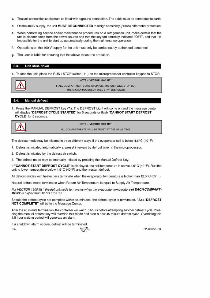
c. The unit connection cable must be fittedwith a ground connection. The cablemust be connected to earth.
d. On the 400 V supply, the unitMUSTBE CONNECTED to a high sensibility (30mA) differential protection.
e. When performing service and/or maintenance procedures on a refrigeration unit, make certain that theunit is disconnected from the power source and that the keypad correctly indicates “OFF”, and that it isimpossible for the unit to start up automatically during the maintenance operation.
f. Operations on the 400 V supply for the unit must only be carried out by authorized personnel.
g. The user is liable for ensuring that the above measures are taken.
8.3. Unit shut--down
1. To stop the unit, place the RUN / STOP switch (11.) on the microprocessor controller keypad to STOP.
NOTE -- VECTOR 1800 MT_
IF ALL COMPARTMENTS ARE STOPPED, THE UNIT WILL STOP BUT
THE MICROPROCESSOR WILL STAY ENERGIZED.
8.4. Manual defrost
1. Press the MANUAL DEFROST key (7.). The DEFROST Light will come on and the message centerwill display “DEFROST CYCLE STARTED” for 5 seconds or flash “CANNOT START DEFROSTCYCLE” for 5 seconds.
NOTE -- VECTOR 1800 MT_
ALL COMPARTMENTS WILL DEFROST AT THE SAME TIME.
The defrost mode may be initiated in three different ways if the evaporator coil is below 4.5_C (40_F) :
1. Defrost is initiated automatically at preset intervals by defrost timer in the microprocessor.
2. Defrost is initiated by the defrost air switch.
3. The defrost mode may be manually intiated by pressing the Manual Defrost Key.
If “CANNOT START DEFROST CYCLE” is displayed, the coil temperature is above 4.5_C (40_F). Run theunit to lower temperature below 4.5_C (40_F) and then restart defrost.
All defrost modes with heater bars terminate when the evaporator temperature is higher than 12.5_C (55_F).
Natural defrost mode terminates when Return Air Temperature is equal to Supply Air Temperature.
For VECTOR1800Mt_: the defrostmode terminates when the evaporator temperatureof EACHCOMPART-MENT is higher than 12.5_C (55_F).
Should the defrost cycle not complete within 45 minutes, the defrost cycle is terminated. “A54--DEFROSTNOT COMPLETE” will be in the Message Center.
After the 45minute termination, the controller will wait 1.5 hours beforeattempting another defrost cycle.Pres-sing the manual defrost key will override this mode and start a new 45 minute defrost cycle. Overriding this1.5 hour waiting period will generate an alarm.
If a shutdown alarm occurs, defrost will be terminated.

1562--60558--03
8.5. To change setpoint temperature
1. Wait the display of the compartment for which you want to modify the setpoint (for VECTOR 1800 Mt_)
2. With the setpoint displayed, press the UP ARROW or DOWN ARROW key (4.) to change setpoint tothe desired value.The display will flash to indicate that the setpoint reading being displayed is anon-entered value. The message center will show “"#TO SCROLL, THEN = TO SAVE“ . The setpointdisplay will flash for 5 seconds of until the = (ENTER) key is pressed.
3. Press the = (ENTER) key (5.) to save the new setpoint.
4. Verify that the message “SETPOINT CHANGED” is displayed on the message center for 5 seconds.
Remarks :
-Setpoints of -30_C to +32_C (-22_F to +89_F) may be entered via the keypad. The controller alwaysretains the last entered setpoint in memory.
-You can not change setpoint when unit is in Pretrip or when viewing Alarm List, Data List or FunctionalParameters.
-Depressing the = key (ENTER) will cause the new displayed setpoint value to become active. If thedisplay is flashing and the new value is not entered, after 5 seconds or no keyboard activity, the displaywill flash for 10 seconds with “SETPOINT NOT CHANGED” displayed and then revert back to the lastsetpoint. All other keys are active at this time and may be pushed while the display is flashing.
TIP
YOU MAY PRESS AND HOLD THE UP ARROW OR DOWN ARROW KEY TO CHANGE THE SET-POINT. THE LONGER THE KEY IS HELD, THE FASTER THE SETTING WILL CHANGE.
8.6. Start--Stop operation
1. Press the START/STOP CONTINUOUS key (9.) until the START/STOP Light (2.) on the controllerilluminates.
2. Verify that “START/STOP MODE SELECTED” is displayed on the message center for 5 seconds andthat the START/STOP Light is illuminated. The unit is now in Start-Stop operation.
8.6.1. Start/Stop system -- Road operation
The system works as follows :
D Engine preheat and start-up is automatic.
D When the temperature(s) selected with the thermostat(s) has been reached, the system shuts the dieselengine down.
D Engine shut-downs can be programmed. Shut-down times will be modified depending on the isothermalinsulation of the box, the ambient temperature and the cargo. The shut-down time is pre-programmed in theplant.
The user should determine whether this setting is appropriate for his type of cargo and the insulation of thebodywork (all adjustments are to be made by a Carrier Transicold technician).
Caution : During unit shut-downs, the evaporator fans also stop. Only use this operating mode for productswhich tolerate shut-downs of this kind.

16 62--60558--03
D The start/stop system comprises several safety devices which ensure it operates correctly. These check:
-the battery status-the temperature of the engine water-the minimum run time
Automatic start/stop is provided to permit starting/restarting of the compressor as required. This gives themicroprocessor automatic control of starting and stopping the diesel engine. The main function of automaticstart-stop is to turn off the refrigeration system near the setpoint to provide a fuel efficient temperature controlsystem and then restart the engine when needed. Start-stop operation is normally used for frozen loads only.
If pressing the START/STOP CONTINUOUS key seems to have no effect, this key may be locked out.START--STOP and CONTINUOUS operation may be tied to the setpoint ranges for frozen and perishableloads.
If the unit fails to start, shuts downon a safety, or fails to run for theminimumrun time, three consecutive times,the “Auto-Start/Failure” is activated.
The microprocessor controller monitors box temperatures, battery voltage, and engine coolant temperature.Once setpoints are reached the controller will shut off the diesel engine to conserve fuel. The controller willnot shut off the engine if the battery voltage is not sufficient to restart it.
The controller will restart the engine if the box temperature is
-more than +6_C (+11_F) (programmable) over setpoint,
-the battery voltage drops below 12.2 VDC, or if
-the engine coolant temperature drops below +0_C.
8.6.2. Start/Stop system -- Standby operation
D Start/Stop :
-The unit will start for a minimum of 5 minutes.
-The unit will stop for a minimum of 5 minutes.
D Continuous Run :
-Only for setpoint above -12_C (²12_C )
8.7. Continuous run operation
1. Press the START/STOP CONTINUOUS key ((9.) until the CONTINUOUS RUN Light (2.) on thecontroller illuminates.
2. Verify that “CONTINUOUS RUN MODE SELECTED” is displayed on the message center and that theCONTINUOUS RUN Light is illuminated. The unit is now in Continuous Run operation.
Remarks :
-In the continuous run mode, the diesel engine will not shut down except for safeties or if the enginestalls. Continuous Run operation is normally used for perishable loads.
-If pressing the START/STOP CONTINUOUS key seems to have no affect, this key may be locked out.Start--Stop and Continuous operation may be tied to the setpoint ranges for frozen and perishable loads.

1762--60558--03
8.8. Pretrip
1. Press the SELECT key (10.) until “PRESS = TO START PRETRIP“ is displayed.
2. Press the = key (5.) to start PRETRIP.
3. Verify that the display shows TEST#.
Remarks :
-The PRETRIP mode is for checking unit operation and evaluating operation of all modes and indicatinga failure when detected.
-The message center displays the current test and the % complete of the test. When the Pretrip testsare complete the message center will display “PRETRIP PASS” or “PRETRIP FAIL IN TEST<testnumber>”. If “PRETRIP FAIL IN TEST<test number>” is displayed the ALARM light will flash. Pressthe ALARM LIST key to review the alarms set by the Pretrip tests.
-Once pretrip is started, the control panel keys are disabled until the pretrip ends.
8.9. Trip start
1. To mark the start of a trip in the data recorder, press the SELECT key (10.) until “PRESS = TO MARKTRIP START” is lit.
2. Press the = key (5.).
3. If trip start is acknowledged by the data recorder, “TRIP START ENTERED” will be displayed for 5seconds and then the display will revert back to the normal display. Otherwise “CANNOT ENTER TRIPSTART” will flash and then the display will revert back to the normal display.
Remarks :
-Trip start marks a time stamp in memory to allow easy review of the data from the last trip.
-Trip start tells the recorder that the present date and time is beginning of a new trip.
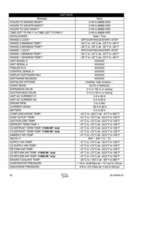
8.10. To display unit data
1. Press the SELECT key (10.) until “PRESS "# TO VIEW DATA” is displayed.
2. Press the = key (5.).
3. Press the UP ARROW or DOWN ARROW key (4.) to display the next or previous unit data value.UNIT DATA
Message ValueTOTAL ENGINE HOURS: 0 HR to 99999 HRSTOTAL STANDBY HOURS 0 HR to 99999 HRSTOTAL SWITCH ON HOURS: 0 HR to 99999 HRSOTHER HOUR METERS & COUNTERS 0 HR to 99999 HRS
ENGINE PROTECT HOURSSWITCH ON PROTECT HOURS:ENGINE SLEEP HOURS:SWITCH ON SLEEP HOURS:HIGH SPEED HOURS:START CYCLES:
18 62--60558--03
UNIT DATA
Message ValueHOURS TO ENGINE MAINT:* 0 HR to 99999 HRSHOURS TO S/B MTR MAINT:* 0 HR to 99999 HRSHOURS TO UNIT MAINT:* 0 HR to 99999 HRSTIME LEFT TO PM 1:* to TIME LEFT TO PM 5:* 0 HR to 99999 HRSDATALOGGER: Date / TimeRANGE 2 LOCK:* OFF/CONTINOUS/START--STOPRANGE 2 MINIMUM TEMP:* --30˚C to +32˚C or --22˚F to +90˚FRANGE 2 MAXIMUM TEMP:* --30˚C to +32˚C or --22˚F to +90˚FRANGE 1 LOCK:* OFF/CONTINOUS/START--STOPRANGE 1 MINIMUM TEMP:* --30˚C to +32˚C or --22˚F to +90˚FRANGE 1 MAXIMUM TEMP:* --30˚C to +32˚C or --22˚F to +90˚FUNIT MODEL #: XXXXXXUNIT SERIAL #: XXXXXXTRAILER ID #: XXXXXXCONTROL SERIAL #: XXXXXXDISPLAY SOFTWARE REV: XXXXXXSOFTWARE REVISION: XXXXXXINSTALLED OPTIONS IntelliSet, High Ambient ...START MODE: AUTO or MANUALEXPANSION VALVE: 0 % to 100 % or closingSUCTION MOD VALVE: 0 % to 100 % or closingUNIT AC CURRENT #1: 0 A to 60 AUNIT AC CURRENT #2: 0 A to 60 AENGINE RPM: 0 to 3 000CURRENT DRAW: --80 A to 80 ABATTERY: 0 V to 28 VCOMP DISCHARGE TEMP: --40˚C to +200˚C or --40˚F to 392˚FEVAP OUTLET TEMP: --47˚C to +70˚C or --52.6˚F to 158˚FSUCTION LINE TEMP: --47˚C to +70˚C or --52.6˚F to 158˚FDEFROST TERM TEMP 1: --47˚C to +70˚C or --52.6˚F to 158˚FC2 DEFROST TERM TEMP: V1800 Mt_ only --47˚C to +70˚C or --52.6˚F to 158˚FC3 DEFROST TERM TEMP: V1800 Mt_ only --47˚C to +70˚C or --52.6˚F to 158˚FAMBIENT AIR TEMP: --47˚C to +70˚C or --52.6˚F to 158˚FDELTA--T: RAT -- SAT (˚C / ˚F)SUPPLY AIR TEMP: --47˚C to +70˚C or --52.6˚F to 158˚FC2 SUPPLY AIR TEMP: --47˚C to +70˚C or --52.6˚F to 158˚FRETURN AIR TEMP: --47˚C to +70˚C or --52.6˚F to 158˚FC2 RETURN AIR TEMP: V1800 Mt_ only --47˚C to +70˚C or --52.6˚F to 158˚FC3 RETURN AIR TEMP: V1800 Mt_ only --47˚C to +70˚C or --52.6˚F to 158˚FENGINE COOLANT TEMP: --50˚C to +130˚C or --58˚F to 266˚FEVAPORATOR PRESSURE: --1 B to +6.88 Bars or --14.7 psi to 100 psiDISCHARGE PRESSURE: 0 B to +34.4 Bars or 0 psi to 500 psi
1962--60558--03
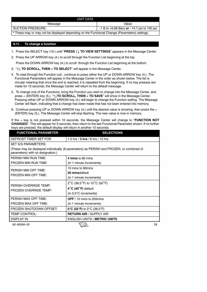
UNIT DATA
Message ValueSUCTION PRESSURE: --1 B to +6.88 Bars or --14.7 psi to 100 psi* These may or may not be displayed depending on the Functional Change (Parameters) settings.
8.11. To change a function
1. Press the SELECT key (10.) until “PRESS "# TO VIEW SETTINGS” appears in the Message Center.
2. Press the UP ARROW key (4.) to scroll through the Function List beginning at the top.
Press the DOWN ARROW key (4.) to scroll through the Function List beginning at the bottom.
3. “"# TO SCROLL, THEN = TO SELECT” will appear in the Message Center.
4. To read through the Function List , continue to press either the UP or DOWN ARROW key (4.). TheFunctional Parameters will appear in the Message Center in the order as shown below. The list iscircular meaning that once the end is reached, it is repeated from the beginning. If no key presses aremade for 10 seconds, the Message Center will return to the default message.
5. To change one of the Functions, bring the Function you wish to change into the Message Center, andpress = (ENTER) key (5.). “"#TO SCROLL, THEN = TO SAVE” will show in the Message Center.Pressing either UP or DOWN ARROW key (4.) will begin to change the Function setting. The MessageCenter will flash, indicating that a change has been made that has not been entered into memory.
6. Continue pressing UP or DOWN ARROW key (4.) until the desired value is showing, then press the =(ENTER) key (5.). The Message Center will stop flashing. The new value is now in memory.
If the = key is not pressed within 10 seconds, the Message Center will change to “FUNCTION NOTCHANGED”. This will appear for 5 seconds, then return to the last Functional Parameter shown. If no furtherkeys are pressed, the default display will return in another 10 seconds.
FUNCTIONAL PARAMETER SELECTIONS
DEFROST TIMER SET FOR 1.5 hrs / 3 hrs / 6 hrs / 12 hrs
SET S/S PARAMETERS:
(These may be displayed individually (8 parameters) as PERISH and FROZEN, or combined (4parameters) with no designation.)
PERISH MIN RUN TIME:
FROZEN MIN RUN TIME:
4 mins to 60 mins(in 1 minute increments)
PERISH MIN OFF TIME:
FROZEN MIN OFF TIME:
10 mins to 90mins
20 minsdefault(in 1 minute increments)
PERISH OVERRIDE TEMP:
FROZEN OVERRIDE TEMP:
2°C (38.5°F) to 10°C (50°F)4°C (40°F) default(in 0.5°C increments)
PERISH MAX OFF TIME:
FROZEN MAX OFF TIME:
OFF / 10 mins to 255mins(in 1 minute increments)
FROZEN SHUTDOWN OFFSET: 0°C (32°F) to 2°C (38.5°F)
TEMP CONTROL: RETURN AIR / SUPPLY AIR
DISPLAY IN ENGLISH UNITS / METRIC UNITS

20 62--60558--03
SELECTIONSFUNCTIONAL PARAMETER
* SET PM HOURMETERS:
S ENGINE
S SWITCH ON
S PM 1 thru PM 55
ON / OFF / RESUME / RESET --
S STANDBY
S SWITCH ON
S PM 1 thru PM 55
ON / OFF / RESUME / RESET --
OUT OF RANGE ALARM: OFF / 2°C (4°F) / 3°C (5.5°F) / 4°C (7°F)
C2 OUT OF RANGE ALARM: OFF / 2°C (4°F) / 3°C (5.5°F) / 4°C (7°F)
C3 OUT OF RANGE ALARM: OFF / 2°C (4°F) / 3°C (5.5°F) / 4°C (7°F)
SLEEP MODE: NO / YES
* OVERRIDE DOOR SHUTDOWN: NO / YES
* OVERRIDE REMS1 SHUTDOWN:
* OVERRIDE REMS2 SHUTDOWN:NO / YES
SILENT MODE NO / YES
ECO MODE: YES or ECO MODE: NO NO / YES
NO POWER--SWITCH TO DIESEL: NO / YES
Selections in BOLD are the factory settings.
* This FunctionalParametermay not appear in the list for your unit, dependingon how themicroprocessor hasbeen configured.
2162--60558--03
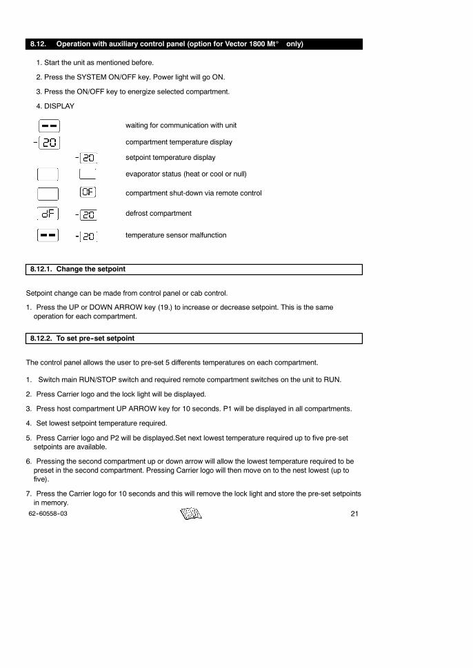
8.12. Operation with auxiliary control panel (option for Vector 1800 Mt_ only)
1. Start the unit as mentioned before.
2. Press the SYSTEM ON/OFF key. Power light will go ON.
3. Press the ON/OFF key to energize selected compartment.
4. DISPLAY
waiting for communication with unit
compartment temperature display
setpoint temperature display
evaporator status (heat or cool or null)
compartment shut-down via remote control
defrost compartment
temperature sensor malfunction
8.12.1. Change the setpoint
Setpoint change can be made from control panel or cab control.
1. Press the UP or DOWN ARROW key (19.) to increase or decrease setpoint. This is the sameoperation for each compartment.
8.12.2. To set pre--set setpoint
The control panel allows the user to pre-set 5 differents temperatures on each compartment.
1. Switch main RUN/STOP switch and required remote compartment switches on the unit to RUN.
2. Press Carrier logo and the lock light will be displayed.
3. Press host compartment UP ARROW key for 10 seconds. P1 will be displayed in all compartments.
4. Set lowest setpoint temperature required.
5. Press Carrier logo and P2 will be displayed.Set next lowest temperature required up to five pre-setsetpoints are available.
6. Pressing the second compartment up or down arrow will allow the lowest temperature required to bepreset in the second compartment. Pressing Carrier logo will then move on to the nest lowest (up tofive).
7. Press the Carrier logo for 10 seconds and this will remove the lock light and store the pre-set setpointsin memory.

22 62--60558--03
8.12.3. To remove pre--set setpoint
1. Switch main RUN/STOP switch and required remote compartment switches on the unit to RUN.
2. Press Carrier logo and the lock light will be displayed.
3. Press host compartment up arrow for 10 seconds. P1 will be displayed in all compartments.
4. Set temperature to lowest possible and OFF will be displayed.
5. Press the UP ARROW key on remote compartments will display the presets, take the temperature tothe lowest possible and OFF will be displayed.
6. Press the Carrier logo for 10 seconds and the new information will be stored in memory.
8.12.4. To lock and unlock the control panel
1. Press the CARRIER logo 10 seconds to lock the control panel.
2. then, starts to flash in the new logic.
3. Press again the CARRIER logo 10 seconds to unlock.
4. The indicator goes off.
NOTE
It is not necessary for the compartment to be running in order to modify or see the setpoint value andthe temperature of the compartment.
The unit can be shut down both with the control panel and the general switch.
2362--60558--03
9. PROBLEMS
Everything possible has been done to ensure that your unit is the most reliable, trouble--free equipmentavailable on themarket today. If, however, you run into problems, the following section may be of assistance.
If you do not find the trouble that you have experienced listed below, please call your Carrier Transicold dealerfor assistance.
9.1. Fuses location
Refer to the electrical schematic provided with the unit.
9.2. Fault alarm display and safety features
9.2.1. Alarm and default messages
Unit problems detected by the controller are stored in the Alarm List in the controller. Stored alarms may beviewed in the Message Center.
All most times, the “STATUS OK” message will be shown in the message center.
Examples of default messages :
-When the unit is due for service or preventative maintenance (PM). “PM DUE” will be shown until theunit is taken in for the PM inspection and the PM timer is reset.
-If there is a problem with the data recorder, “DATA RECORDER FAILURE” will be shown.
-If there is a problem within the Microprocessor, the alarm “249--MICROPROCESSOR ERROR” will beshown.
If a problem begins to develop one of the following messages may be shown :
“CHECK ENGINE OIL LEVEL” means that the engine oil level needs to be checked and oil added.
“CHECK AT NEXT SERVICE INTERVAL” is shown when :
-There is an active non-shutdown alarm present (the alarm condition is present but is not seriousenough to stop the unit). These alarms may be viewed by pressing the ALARM LIST Key. Themessage will clear itself when the condition is corrected.
-If there has been a Shutdown Alarm, and the unit has not yet been into a shop for inspection. Once theshutdown condition has been corrected, the unit may be started, and the alarm message will no longerbe in the Alarm List. This message can only be cleared by a qualified refrigeration technician.
24 62--60558--03
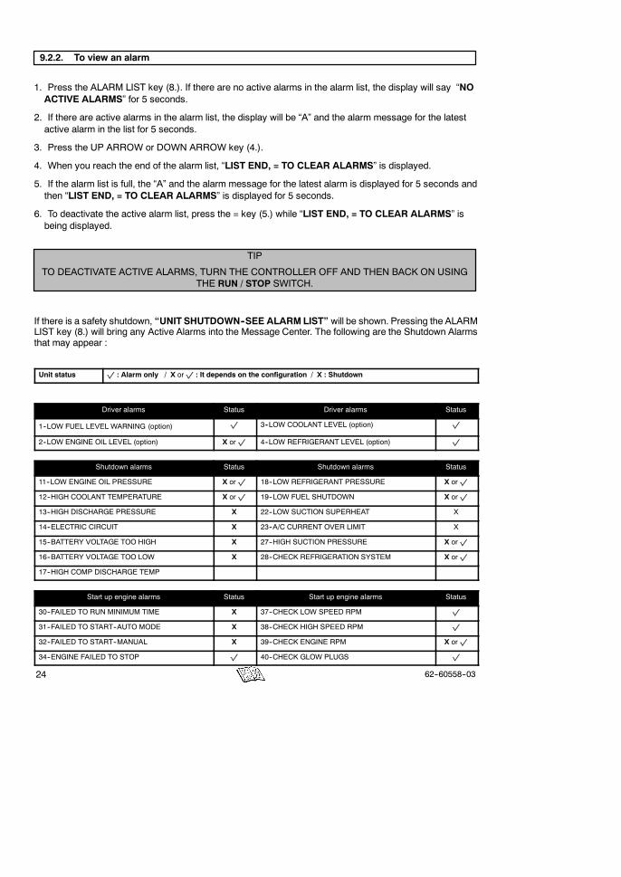
9.2.2. To view an alarm
1. Press the ALARM LIST key (8.). If there are no active alarms in the alarm list, the display will say “NOACTIVE ALARMS” for 5 seconds.
2. If there are active alarms in the alarm list, the display will be “A” and the alarm message for the latestactive alarm in the list for 5 seconds.
3. Press the UP ARROW or DOWN ARROW key (4.).
4. When you reach the end of the alarm list, “LIST END, = TO CLEAR ALARMS” is displayed.
5. If the alarm list is full, the “A” and the alarm message for the latest alarm is displayed for 5 seconds andthen “LIST END, = TO CLEAR ALARMS” is displayed for 5 seconds.
6. To deactivate the active alarm list, press the = key (5.) while “LIST END, = TO CLEAR ALARMS” isbeing displayed.
TIP
TO DEACTIVATE ACTIVE ALARMS, TURN THE CONTROLLER OFF AND THEN BACK ON USINGTHE RUN / STOP SWITCH.
If there is a safety shutdown, “UNIT SHUTDOWN--SEE ALARMLIST” will be shown. Pressing the ALARMLIST key (8.) will bring any Active Alarms into the Message Center. The following are the Shutdown Alarmsthat may appear :
Unit status p : Alarm only / X orp : It depends on the configuration / X : Shutdown
Driver alarms Status Driver alarms Status
1--LOW FUEL LEVEL WARNING (option) p 3--LOW COOLANT LEVEL (option) p
2--LOW ENGINE OIL LEVEL (option) X orp 4--LOW REFRIGERANT LEVEL (option) p
Shutdown alarms Status Shutdown alarms Status
11--LOW ENGINE OIL PRESSURE X orp 18--LOW REFRIGERANT PRESSURE X orp
12--HIGH COOLANT TEMPERATURE X orp 19--LOW FUEL SHUTDOWN X orp
13--HIGH DISCHARGE PRESSURE X 22--LOW SUCTION SUPERHEAT X
14--ELECTRIC CIRCUIT X 23--A/C CURRENT OVER LIMIT X
15--BATTERY VOLTAGE TOO HIGH X 27--HIGH SUCTION PRESSURE X orp
16--BATTERY VOLTAGE TOO LOW X 28--CHECK REFRIGERATION SYSTEM X orp
17--HIGH COMP DISCHARGE TEMP
Start up engine alarms Status Start up engine alarms Status
30--FAILED TO RUN MINIMUM TIME X 37--CHECK LOW SPEED RPM p
31--FAILED TO START--AUTO MODE X 38--CHECK HIGH SPEED RPM p
32--FAILED TO START--MANUAL X 39--CHECK ENGINE RPM X orp
34--ENGINE FAILED TO STOP p 40--CHECK GLOW PLUGS p

2562--60558--03
StatusStart up engine alarmsStatusStart up engine alarms
35--CHECK STARTER CIRCUIT X orp 41--ENGINE STALLED X
36--CHECK COOLANT TEMPERATURE p
Warning / status alarms Status Warning / status alarms Status
51--ALTERNATOR NOT CHARGING X orp 58--CHECK REMOTE SWITCH 2 -- Vector 1800 p
53--BOX TEMP OUT--OF--RANGE p 59--DATALOGGER NOT RECORDING p
54--DEFROST NOT COMPLETE p 60--DATALOGGER TIME WRONG p
55--CHECK DEFROST AIR SWITCH p 61--DOOR OPEN p
56--CHECK EVAPORATOR AIRFLOW p 62--C2 BOX TEMP OUT--OF--RANGE -- V1800 Mt_ X orp
57--CHECK REMOTE SWITCH 1 -- Vector 1800 p 63--C3 BOX TEMP OUT--OF--RANGE -- V1800 Mt_ X orp
Electrical alarms Status Electrical alarms uStatus
71--BAD F2 OR F3 FUSE p 92--CHECK HEATER CONTACTOR 2 p
72--BAD F4 OR F6 FUSE p 93--CHECK STARTUP BUZZER p
73--NO POWER-- CHECK POWER CORD X 94--CHECK COMP CONTACTOR 1 p
74--AC PHASE REVERSED X orp 95--CHECK COND FAN CONTACTOR 1 p
75--COMP MOTOR OVERHEATED X 96--CHECK GENERATOR CONTACTOR p
76--CONDENSER MOTOR OVERHEATED X 97--CHECK SV2 CIRCUIT p
77--EVAP MOTOR OVERHEATED X 98--CHECK HIGH TEMP THERMOSTAT X bothelectricheaters
78--CHECK SV1 CIRCUIT p 99--CHECK STANDBY CONTACTOR p
79--CHECK SV4 CIRCUIT p 100--OVERLOAD / GROUND FAULT p
80--CHECK SV3 CIRCUIT p 101--C2 EVAP MOTOR OVERHEATED -- V1800 Mt_ p
81--CHECK FHR CIRCUIT p 102--C3 EVAP MOTOR OVERHEATED -- V1800 Mt_ p
82--CHK REMOTE OUT--RANGE LIGHT -- V1800 p 103--C2 CHK HEATER CONTACTOR 1 -- V1800 Mt_ p
83--CHECK REMOTE DEFROST LIGHT p 104--C2 CHK HEATER CONTACTOR 2 -- V1800 Mt_ p
84--CHECK REMOTE ALARM LIGHT p 105--C3 CHK HEATER CONTACTOR 1-- V1800 Mt_ p
85--CHECK UL1 CIRCUIT p 106--C3 CHK HEATER CONTACTOR 2-- V1800 Mt_ p
86--CHECK UL2 CIRCUIT p 107--C2 CHECK LSV -- Vector 1800 Mt_ p
87--CHECK REMOTE HEAT LIGHT -- V1800 p 108--C3 CHECK LSV -- Vector 1800 Mt_ p
88--CHECK REMOTE COOL LIGHT -- V1800 p 109--CHECK EVAP FAN CONTACTOR p
89--CHECK REMOTE AUTO LIGHT p 110--C2 CHK EVAP FAN CONTACTOR -- V1800 Mt_ p
90--CHK AFA SOLENOID CIRCUIT p 111--C3 CHK EVAP FAN CONTACTOR -- V1800 Mt_ p
91--CHECK HEATER CONTACTOR 1
Sensor alarms Status Sensor alarms Status
121--CHECK AMBIENT AIR SENSOR p 121--CHECK AMBIENT AIR SENSOR p
122--CHECK RETURN AIR SENSOR X 122--CHECK RETURN AIR SENSOR X
123--CHECK SUPPLY AIR SENSOR X 132--CHK DEFROST TERM 2 SENSOR p
124--CHK DEFROST TERM 1 SENSOR p 133--CHEK REMOTE TEMP SENSOR 1 p
125--CHECK COMP DISCH SENSOR p 134--CHEK REMOTE TEMP SENSOR 2 p
26 62--60558--03
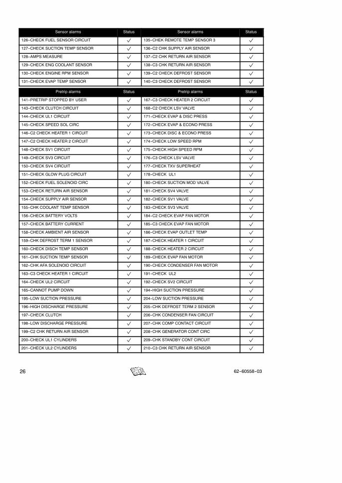
StatusSensor alarmsStatusSensor alarms
126--CHECK FUEL SENSOR CIRCUIT p 135--CHEK REMOTE TEMP SENSOR 3 p
127--CHECK SUCTION TEMP SENSOR p 136--C2 CHK SUPPLY AIR SENSOR p
128--AMPS MEASURE p 137--C2 CHK RETURN AIR SENSOR p
129--CHECK ENG COOLANT SENSOR p 138--C3 CHK RETURN AIR SENSOR p
130--CHECK ENGINE RPM SENSOR p 139--C2 CHECK DEFROST SENSOR p
131--CHECK EVAP TEMP SENSOR p 140--C3 CHECK DEFROST SENSOR p
Pretrip alarms Status Pretrip alarms Status
141--PRETRIP STOPPED BY USER p 167--C3 CHECK HEATER 2 CIRCUIT p
143--CHECK CLUTCH CIRCUIT p 168--C2 CHECK LSV VALVE p
144--CHECK UL1 CIRCUIT p 171--CHECK EVAP & DISC PRESS p
145--CHECK SPEED SOL CIRC p 172--CHECK EVAP & ECONO PRESS p
146--C2 CHECK HEATER 1 CIRCUIT p 173--CHECK DISC & ECONO PRESS p
147--C2 CHECK HEATER 2 CIRCUIT p 174--CHECK LOW SPEED RPM p
148--CHECK SV1 CIRCUIT p 175--CHECK HIGH SPEED RPM p
149--CHECK SV3 CIRCUIT p 176--C3 CHECK LSV VALVE p
150--CHECK SV4 CIRCUIT p 177--CHECK TXV SUPERHEAT p
151--CHECK GLOW PLUG CIRCUIT p 178--CHECK UL1 p
152--CHECK FUEL SOLENOID CIRC p 180--CHECK SUCTION MOD VALVE p
153--CHECK RETURN AIR SENSOR p 181--CHECK SV4 VALVE p
154--CHECK SUPPLY AIR SENSOR p 182--CHECK SV1 VALVE p
155--CHK COOLANT TEMP SENSOR p 183--CHECK SV3 VALVE p
156--CHECK BATTERY VOLTS p 184--C2 CHECK EVAP FAN MOTOR p
157--CHECK BATTERY CURRENT p 185--C3 CHECK EVAP FAN MOTOR p
158--CHECK AMBIENT AIR SENSOR p 186--CHECK EVAP OUTLET TEMP p
159--CHK DEFROST TERM 1 SENSOR p 187--CHECK HEATER 1 CIRCUIT p
160--CHECK DISCH TEMP SENSOR p 188--CHECK HEATER 2 CIRCUIT p
161--CHK SUCTION TEMP SENSOR p 189--CHECK EVAP FAN MOTOR p
162--CHK AFA SOLENOID CIRCUIT p 190--CHECK CONDENSER FAN MOTOR p
163--C3 CHECK HEATER 1 CIRCUIT p 191--CHECK UL2 p
164--CHECK UL2 CIRCUIT p 192--CHECK SV2 CIRCUIT p
165--CANNOT PUMP DOWN p 194--HIGH SUCTION PRESSURE p
195--LOW SUCTION PRESSURE p 204--LOW SUCTION PRESSURE p
196--HIGH DISCHARGE PRESSURE p 205--CHK DEFROST TERM 2 SENSOR p
197--CHECK CLUTCH p 206--CHK CONDENSER FAN CIRCUIT p
198--LOW DISCHARGE PRESSURE p 207--CHK COMP CONTACT CIRCUIT p
199--C2 CHK RETURN AIR SENSOR p 208--CHK GENERATOR CONT CIRC p
200--CHECK UL1 CYLINDERS p 209--CHK STANDBY CONT CIRCUIT p
201--CHECK UL2 CYLINDERS p 210--C3 CHK RETURN AIR SENSOR p
2762--60558--03
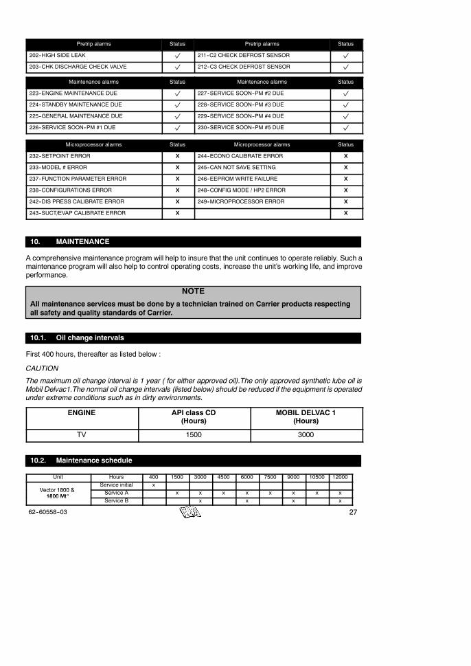
StatusPretrip alarmsStatusPretrip alarms
202--HIGH SIDE LEAK p 211--C2 CHECK DEFROST SENSOR p
203--CHK DISCHARGE CHECK VALVE p 212--C3 CHECK DEFROST SENSOR p
Maintenance alarms Status Maintenance alarms Status
223--ENGINE MAINTENANCE DUE p 227--SERVICE SOON--PM #2 DUE p
224--STANDBY MAINTENANCE DUE p 228--SERVICE SOON--PM #3 DUE p
225--GENERAL MAINTENANCE DUE p 229--SERVICE SOON--PM #4 DUE p
226--SERVICE SOON--PM #1 DUE p 230--SERVICE SOON--PM #5 DUE p
Microprocessor alarms Status Microprocessor alarms Status
232--SETPOINT ERROR X 244--ECONO CALIBRATE ERROR X
233--MODEL # ERROR X 245--CAN NOT SAVE SETTING X
237--FUNCTION PARAMETER ERROR X 246--EEPROM WRITE FAILURE X
238--CONFIGURATIONS ERROR X 248--CONFIG MODE / HP2 ERROR X
242--DIS PRESS CALIBRATE ERROR X 249--MICROPROCESSOR ERROR X
243--SUCT/EVAP CALIBRATE ERROR X X
10. MAINTENANCE
A comprehensive maintenance program will help to insure that the unit continues to operate reliably. Such amaintenance program will also help to control operating costs, increase the unit’s working life, and improveperformance.
NOTE
All maintenance services must be done by a technician trained on Carrier products respectingall safety and quality standards of Carrier.
10.1. Oil change intervals
First 400 hours, thereafter as listed below :
CAUTION
The maximum oil change interval is 1 year ( for either approved oil).The only approved synthetic lube oil isMobil Delvac1.The normal oil change intervals (listed below) should be reduced if the equipment is operatedunder extreme conditions such as in dirty environments.
ENGINE API class CD(Hours)
MOBIL DELVAC 1(Hours)
TV 1500 3000
10.2. Maintenance schedule
Unit Hours 400 1500 3000 4500 6000 7500 9000 10500 12000
Vector 1800 &Service initial x
Vector 1800 &1800 Mt_
Service A x x x x x x x x1800 Mt_
Service B x x x x

28 62--60558--03
10.3. Services description
Service initial
Check the tightness of bolts and screws and that the unit is correctlyfastened onto the box
Tighten all electrical connection in control box
Drain the engine oil, replace oil filter
Service A
Pretrip inspection
Drain the engine oil, replace oil filter
Replace air filter element
Replace fuel filter
Clean up condenser & radiator coil
Check defrost system
Tighten all electrical connection in control box
Service B
Operation of Service A,
Calibrate defrost air switch
Check water pump bearing and belt
Check fuel pump filter
Check starter condition
Check and adjust nozzle injectors
Grease control rods of diesel engine
Check level of coolant, refrigerant and battery electrolyte
Check battery charger charge
Check regulation operation (cool--nul--heat)
Check manual/automatic defrost operation
Check operation of solenoid
Check klixon cut out
Check motor speed in high speed and low speed
Check fuel hoses
Check coolant hoses
Tighten all electrical connection in control box
EVERY TWO YEAR
Replace filter drier
Replace compressor oil -- only use Ester oil (POE) approved by CarrierTransicold
Replace refrigerant (type : R404A)
Tighten all electrical connection in control box
EVERY FIVE YEARor 10000 hours
Replace all fuel hoses

2962--60558--03
10.4. Recommended oil
Engine oil : The oils recommended for use in your refrigeration unit must comply with the AmericanPetroleumInstitute’s (API) SG/CD rating. The use of oil of the proper weight (viscosity) is also essential. The followingchart indicates the SAE Weight Rating of the oil to be used in various climates :
and over
10W or 10W30
20W or 15W40
30W or15W40
The following oils are accepted for use in Europe with the unit.
RECOMMENDED OILS
CARRIERAGIPANTARBP
ELF
FIATFINA
HAFA
IGOL
IMPERATOR
CARRIER TD+15W--40
SIGMA TURBO SHPD 15W--40
GRAPHITE R 15W--40
VANELLUS C3 EXTRA 15W--40
VANELLUS FE 15W30
MULTIPERFORMANCE4D 15W--40
PERFORMANCE TROPHY 15W--40
URANIA TURBO 15W--40
KAPPA LDO 15W--40
KAPPA TD PLUS 15W--40
KAPPA EXTRA 15W--40
DETERGENTE 4DM 15W--40
STRADEX 900 ECO 15W--40
SYNTHIDEX ECO 15W--40
RALLYE TURBO 4E 15W--40
RALLYE TURBO 4E LD 15W--40
RAFF SUPER HPDO 15W--40
LABOMOBIL
OPALORLYPOLAROILRENAULT
TEXACOTOTALSHELL
UNIL
YACCO
MEGAMAXI 15W--40
DELVAC SHC 15W--40
DELVAC 1400 SUPEROPALGET D 500 15W--40
TURBO 2002 15W--40
POLATRUCK 15W--40
KMX 2 PLUS 15W--30
KMX 2 PLUS 15W--40
MV5 “EUROPE”URSA SUPER TD 15W--40
RUBIA TIR MAX 15W40
MYRINA TX 15W--40
MYRINA T 15W--30
SUPER ROC 3D 15W--40
TURBO DX 15W--40
SM 4D + 15W--40
30 62--60558--03
11. A.T.P. EUROPE REGULATION EXTRACT
(Date: March 1974)
Approval of vehicles intended for the carriage of perishable goods.
Before putting a refrigerated vehicle into service, it is necessary to have it approved by the Regional HealthDepartment.
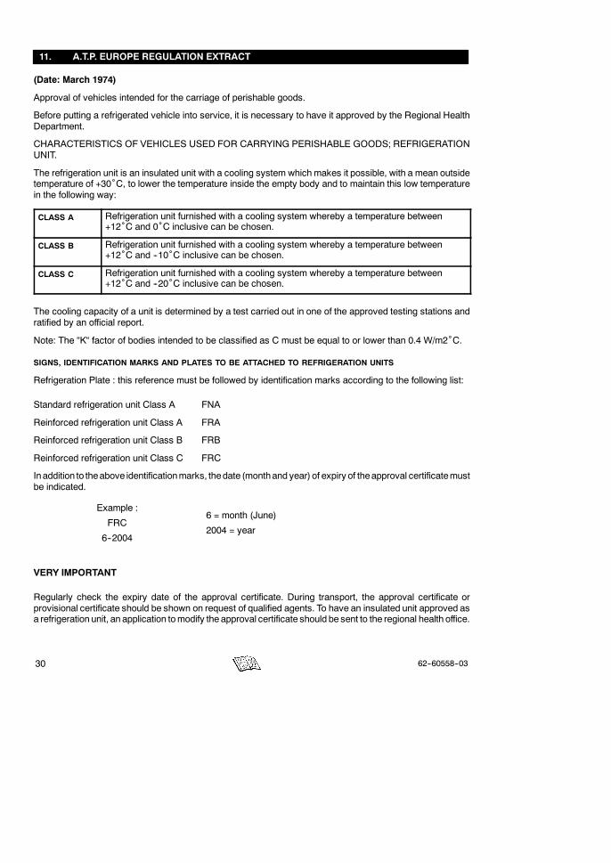
CHARACTERISTICS OF VEHICLES USED FOR CARRYING PERISHABLE GOODS; REFRIGERATIONUNIT.
The refrigeration unit is an insulated unit with a cooling system which makes it possible, with a mean outsidetemperature of +30˚C, to lower the temperature inside the empty body and to maintain this low temperaturein the following way:
CLASS A Refrigeration unit furnished with a cooling system whereby a temperature between+12˚C and 0˚C inclusive can be chosen.
CLASS B Refrigeration unit furnished with a cooling system whereby a temperature between+12˚C and --10˚C inclusive can be chosen.
CLASS C Refrigeration unit furnished with a cooling system whereby a temperature between+12˚C and --20˚C inclusive can be chosen.
The cooling capacity of a unit is determined by a test carried out in one of the approved testing stations andratified by an official report.
Note: The “K“ factor of bodies intended to be classified as C must be equal to or lower than 0.4 W/m2˚C.
SIGNS, IDENTIFICATION MARKS AND PLATES TO BE ATTACHED TO REFRIGERATION UNITS
Refrigeration Plate : this reference must be followed by identification marks according to the following list:
Standard refrigeration unit Class A FNA
Reinforced refrigeration unit Class A FRA
Reinforced refrigeration unit Class B FRB
Reinforced refrigeration unit Class C FRC
Inaddition to theabove identificationmarks, thedate (monthand year) of expiry of theapproval certificatemustbe indicated.
Example :
FRC
6--2004
6 = month (June)
2004 = year
VERY IMPORTANT
Regularly check the expiry date of the approval certificate. During transport, the approval certificate orprovisional certificate should be shown on request of qualified agents. To have an insulated unit approved asa refrigeration unit, an application tomodify the approval certificate should be sent to the regional health office.
3162--60558--03
12. 24H ASSISTANCE
At Carrier Transicold we’re working hard to give you complete service when and where you need it. Thatimplies a worldwide network of dealers and available an emergency service. These service centers aremanned by factory--trained service personnel and backed by extensive parts inventories that will assure youof prompt repair.
Should you encounter a unit problem with your refrigeration unit during transit, follow your company’semergency procedure or contact the nearest Carrier Transicold service center. Consult the directory to locatethe service center nearest you. This directory may be obtained from your Carrier Transicold dealer.
If you are unable to reach a service center, call Carrier Transicold’s 24 Hour Assistance :
In Europe, please use the following free phone numbers from :
A AUSTRIA 0800 291039B BELGIUM 0800 99310CH SWITZERLAND 0800 838839D GERMANY 0800 1808180DK DENMARK 808 81832E SPAIN 900 993213F FRANCE 0800 913148FIN FINLAND 0800 113221GB GREAT BRITAIN 0800 9179067GR GREECE 00800 3222523H HUNGARY 06800 13526I ITALY 800 791033
IRL IRELAND 1800 553286L LUXEMBURG 800 3581
RUS RUSSIA 810 800 200 31032N NORWAY 800 11435NL THE NETHERLANDS 0800 0224894P PORTUGAL 8008 32283PL POLAND 00800 3211238S SWEDEN 020 790470
From other countries or direct : +32 9 255 67 89
In Canada or United States, call 1 -- 800 -- 448 -- 1661.
When calling, please have the following information ready for fastest service :
- Your name, the name of your company, and your location.- A telephone number where you can be called back.
- Refrigeration unit model number and serial number.- Box temperature, set--point and product.- Brief description of the problem you are having, and what you have already done to correct theproblem.
We will do everything we can to get your problem taken care of and get you back on the road.

32 62--60558--03