operating instructions and parts manual 4-ft. radial arm drill
TRANSCRIPT
1
Operating Instructions and Parts Manual 4-ft. Radial Arm Drill Press Models J-1230R, J-1230R-4
WALTER MEIER (Manufacturing) Inc. 427 New Sanford Road LaVergne, Tennessee 37086 Part No. M-320036 Ph.: 800-274-6848 Revision B 07/2011 www.waltermeier.com Copyright © 2011 Walter Meier (Manufacturing) Inc.
2
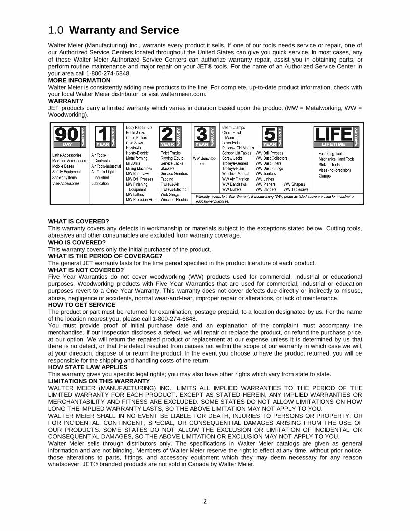
1.0 Warranty and Service Walter Meier (Manufacturing) Inc., warrants every product it sells. If one of our tools needs service or repair, one of our Authorized Service Centers located throughout the United States can give you quick service. In most cases, any of these Walter Meier Authorized Service Centers can authorize warranty repair, assist you in obtaining parts, or perform routine maintenance and major repair on your JET® tools. For the name of an Authorized Service Center in your area call 1-800-274-6848. MORE INFORMATION Walter Meier is consistently adding new products to the line. For complete, up-to-date product information, check with your local Walter Meier distributor, or visit waltermeier.com. WARRANTY JET products carry a limited warranty which varies in duration based upon the product (MW = Metalworking, WW = Woodworking).
WHAT IS COVERED? This warranty covers any defects in workmanship or materials subject to the exceptions stated below. Cutting tools, abrasives and other consumables are excluded from warranty coverage. WHO IS COVERED? This warranty covers only the initial purchaser of the product. WHAT IS THE PERIOD OF COVERAGE? The general JET warranty lasts for the time period specified in the product literature of each product. WHAT IS NOT COVERED? Five Year Warranties do not cover woodworking (WW) products used for commercial, industrial or educational purposes. Woodworking products with Five Year Warranties that are used for commercial, industrial or education purposes revert to a One Year Warranty. This warranty does not cover defects due directly or indirectly to misuse, abuse, negligence or accidents, normal wear-and-tear, improper repair or alterations, or lack of maintenance. HOW TO GET SERVICE The product or part must be returned for examination, postage prepaid, to a location designated by us. For the name of the location nearest you, please call 1-800-274-6848. You must provide proof of initial purchase date and an explanation of the complaint must accompany the merchandise. If our inspection discloses a defect, we will repair or replace the product, or refund the purchase price, at our option. We will return the repaired product or replacement at our expense unless it is determined by us that there is no defect, or that the defect resulted from causes not within the scope of our warranty in which case we will, at your direction, dispose of or return the product. In the event you choose to have the product returned, you will be responsible for the shipping and handling costs of the return. HOW STATE LAW APPLIES This warranty gives you specific legal rights; you may also have other rights which vary from state to state. LIMITATIONS ON THIS WARRANTY WALTER MEIER (MANUFACTURING) INC., LIMITS ALL IMPLIED WARRANTIES TO THE PERIOD OF THE LIMITED WARRANTY FOR EACH PRODUCT. EXCEPT AS STATED HEREIN, ANY IMPLIED WARRANTIES OR MERCHANTABILITY AND FITNESS ARE EXCLUDED. SOME STATES DO NOT ALLOW LIMITATIONS ON HOW LONG THE IMPLIED WARRANTY LASTS, SO THE ABOVE LIMITATION MAY NOT APPLY TO YOU. WALTER MEIER SHALL IN NO EVENT BE LIABLE FOR DEATH, INJURIES TO PERSONS OR PROPERTY, OR FOR INCIDENTAL, CONTINGENT, SPECIAL, OR CONSEQUENTIAL DAMAGES ARISING FROM THE USE OF OUR PRODUCTS. SOME STATES DO NOT ALLOW THE EXCLUSION OR LIMITATION OF INCIDENTAL OR CONSEQUENTIAL DAMAGES, SO THE ABOVE LIMITATION OR EXCLUSION MAY NOT APPLY TO YOU. Walter Meier sells through distributors only. The specifications in Walter Meier catalogs are given as general information and are not binding. Members of Walter Meier reserve the right to effect at any time, without prior notice, those alterations to parts, fittings, and accessory equipment which they may deem necessary for any reason whatsoever. JET® branded products are not sold in Canada by Walter Meier.
3
2.0 Table of Contents Section Page
1.0 Warranty and Service ............................................................................................................................................ 2 2.0 Table of Contents .................................................................................................................................................. 3 3.0 Safety...................................................................................................................................................................... 5
3.1 Machinery General Safety Warnings ............................................................................................................... 5 3.2 General Electrical Cautions .............................................................................................................................. 6 3.3 Safety Instructions for Drill Presses ................................................................................................................. 6
4.0 Specifications ......................................................................................................................................................... 7 4.1 Machining Capacities ........................................................................................................................................ 8 4.2 Machine Environment ....................................................................................................................................... 8 4.3 Power Supply Requirements ............................................................................................................................ 8 4.4 Overall Dimensions, J-1230R........................................................................................................................... 9
5.0 General Features and Terminology ................................................................................................................... 10 6.0 Set-Up and Assembly.......................................................................................................................................... 12
6.1 Floor Diagrams for J-1230R ........................................................................................................................... 12 6.2 Unpacking ........................................................................................................................................................ 13 6.3 Machine Set-Up ............................................................................................................................................... 14 6.4 Electrical Connections .................................................................................................................................... 15
7.0 Operating Controls............................................................................................................................................... 16 8.0 Operation .............................................................................................................................................................. 17
8.1 Clamping workpieces ...................................................................................................................................... 17 8.2 Tool insertion ................................................................................................................................................... 17 8.3 Tool Positioning over workpiece .................................................................................................................... 17 8.4 Unlocking arm and column mechanisms....................................................................................................... 18 8.5 Raising and lowering radial arm ..................................................................................................................... 18 8.6 Moving drill head along arm ........................................................................................................................... 18 8.7 Rotating arm on support column .................................................................................................................... 18 8.8 Setting spindle speed...................................................................................................................................... 18 8.9 Feed rate and depth of cut ............................................................................................................................. 19 8.10 Setting feed rate ............................................................................................................................................ 19 8.11 Setting depth of cut using power feed system ............................................................................................ 20 8.12 Spindle direction and power feed................................................................................................................. 20 8.13 Hand feed – roughing operations................................................................................................................. 20 8.14 Fine hand feed using power feed system ................................................................................................... 20 8.15 Tapping .......................................................................................................................................................... 21 8.16 Power ON/OFF .............................................................................................................................................. 21 8.17 Power ON light .............................................................................................................................................. 21 8.18 Coolant control .............................................................................................................................................. 21 8.19 Spindle motor controls .................................................................................................................................. 21 8.20 Turning off spindle drive ............................................................................................................................... 21 8.21 Resetting STOP switch ................................................................................................................................. 21 8.22 Using load ammeter ...................................................................................................................................... 21 8.23 Tapping operations ....................................................................................................................................... 22 8.24 Arm/spindle control lever .............................................................................................................................. 22
9.0 Adjustments ......................................................................................................................................................... 22 9.1 Clamping Device ............................................................................................................................................. 22 9.2 Head/Rail Backlash ......................................................................................................................................... 23
10.0 Spindle Speed Chart ......................................................................................................................................... 24 11.0 Troubleshooting the J-1230R ........................................................................................................................... 25 12.0 Maintenance....................................................................................................................................................... 26
12.1 General Cleaning .......................................................................................................................................... 26 12.2 Lubrication ..................................................................................................................................................... 26
13.0 Replacement Parts ............................................................................................................................................ 28 13.1.1 Riser Mechanism: Exploded View ............................................................................................................ 28 13.1.2 Riser Mechanism: Parts List ..................................................................................................................... 29 13.2.1 Column and Base: Exploded View ........................................................................................................... 30 13.2.2 Column and Base: Parts List..................................................................................................................... 31 13.3.1 Arm (Front): Exploded View ...................................................................................................................... 32 13.3.2 Arm (Front): Parts List ............................................................................................................................... 33 13.4.1 Arm (Rear) and Clamping Gearbox: Exploded View............................................................................... 34
4
13.4.2 Arm (Rear) and Clamping Gearbox: Parts List ........................................................................................ 35 13.5.1 Coolant System: Exploded View............................................................................................................... 37 13.5.2 Coolant System: Parts List ........................................................................................................................ 37 13.6.1 Gearbox Assembly (Head): Exploded View ............................................................................................. 38 13.6.2 Gearbox Assembly (Head): Parts List ...................................................................................................... 39 13.7.1 Rear of Head I: Exploded View ................................................................................................................. 42 13.7.2 Rear of Head I: Parts List .......................................................................................................................... 43 13.8.1 Counterweight Assembly: Exploded View ............................................................................................... 44 13.8.2 Counterweight Assembly: Parts List ......................................................................................................... 44
14.0 Electrical Connections for J-1230R .................................................................................................................. 45 14.1 Electrical Connections for J-1230R: Parts List ........................................................................................... 46
Familiarize yourself with the following safety notices used in this manual:
This means that if precautions are not heeded, it may result in minor injury and/or possible machine damage.
This means that if precautions are not heeded, it may result in serious or even fatal injury.
5
3.0 Safety
- Misuse of this machine can cause serious injury.
- For safety, machine must be set up, used and serviced properly.
- Read, understand and follow instructions in the operator’s and parts manual which was shipped with your machine.
When setting up machine: - Always avoid using machine in damp or poorly
lighted work areas. - Always be sure machine is securely anchored
to the floor. - Always keep machine guards in place. - Always put start switch in “OFF” position before
plugging in machine. When using machine: -Never operate with machine guards missing. -Always wear safety glasses with side shields
(See ANSI Z87.1) -Never wear loose clothing or jewelry. -Never overreach — you may slip and fall into
the machine.
-Never leave machine running while you are away from it.
-Always shut off the machine when not in use. When servicing machine: -Always unplug machine from electrical power
while servicing. -Always follow instructions in operator’s and
parts manual when changing accessory tools or parts.
-Never modify the machine without consulting Walter Meier (Manufacturing) Inc.
Read and follow these simple rules for best results and full benefits from your machine. Used properly, JET machinery is among the best in design and safety. However, any machine used improperly can be rendered inefficient and unsafe. It is mandatory that those who use our products be properly trained in how to use them correctly. They should read and understand the Operating Instructions and Parts Manual as well as all labels affixed to the machine. Failure to follow all of these warnings can cause serious injuries.
3.1 Machinery General Safety Warnings 1. Always wear protective eye wear when
operating machinery. Eye wear shall be impact resistant, protective safety glasses with side shields which comply with ANSI Z87.1 specifications. Use of eye wear which does not comply with ANSI Z87.1 specifications could result in severe injury from breakage of eye protection.
2. Wear proper apparel. No loose clothing or jewelry which can get caught in moving parts. Contain long hair. Rubber soled footwear is recommended for best footing.
3. Do not overreach. Failure to maintain proper working position can cause you to fall into the machine or cause your clothing to get caught — pulling you into the machine.
4. Keep guards in place and in proper working order. Do not operate the machine with guards removed.
5. Avoid dangerous working environments. Do not use stationary machine tools in wet or damp locations, or in an explosive environment. Keep work areas clean and well lit. Special electrics should be used when working on flammable materials.
6. Avoid accidental starts by being sure the start switch is “OFF” before plugging in the machine.
7. Machinery must be anchored to the floor.
8. Never leave the machine running while unattended. Machine shall be shut off whenever it is not in operation.
9. Disconnect electrical power before servicing. Whenever changing accessories or general maintenance is done on the machine, electrical power to the machine must be disconnected before work is done.
10. Maintain all machine tools with care. Follow all maintenance instructions for lubricating and the changing of accessories. No attempt shall be made to modify or have makeshift repairs done to the machine. This not only voids the warranty but also renders the machine unsafe.
11. Secure work. Use clamps or a vise to hold work, when practical. It is safer than using your hands and it frees both hands to operate the machine.
12. Never brush away chips while the machine is in operation.
13. Keep work area clean. Cluttered areas invite accidents.
14. Remove adjusting keys and wrenches before turning machine on.
15. Use the right tool. Don’t force a tool or attachment to do a job for which it was not designed.
6
16. Use only recommended accessories and follow manufacturer’s instructions pertaining to them.
17. Keep hands in sight and clear of all moving parts and cutting surfaces.
18. All visitors should be kept a safe distance from the work area. Make workshop
completely safe by using padlocks, master switches, or by removing starter keys.
19. Know the tool you are using; its application, limitations, and potential hazards.
3.2 General Electrical Cautions This machine should be grounded in accordance with the National Electrical Code and local codes and ordinances. This work should be done by a qualified electrician. The machine should be grounded to protect the user from electrical shock.
Caution: For circuits which are far away from the electrical service box, the wire size must be increased in order to deliver ample voltage to the motor. To minimize power losses and to prevent motor overheating and burnout, the use of wire sizes for branch circuits or electrical extension cords according to the following table is recommended:
Conductor Length AWG Number 240 Volt Lines 120 Volt Lines
0 – 50 Ft. No. 14 No. 14
50 – 100 Ft. No. 14 No. 12
Over 100 Ft. No. 12 No. 8
Table 1
3.3 Safety Instructions for Drill Presses 1. All work shall be secured using either clamps or a vise to the drill press table. It is unsafe to use your
hands to hold any workpiece being drilled. 2. Drill press head and table shall be securely locked to the column before operating the drill press. This
must always be checked prior to starting the machine. 3. Always use the correct tooling. Tooling shall always be maintained and properly sharpened. All
tooling must be run at the proper speeds and feeds as they apply to the job. Use only recommended accessories and follow those manufacturer’s instructions pertaining to them. Tooling shall not be forced into any workpiece but fed according to the proper specifications. Failure to follow these instructions will not only ruin the tooling as well as the machine, but can cause serious injury.
4. Never brush away shavings or chips while the machine is in operation. All clean up should be done after the machine is stopped.
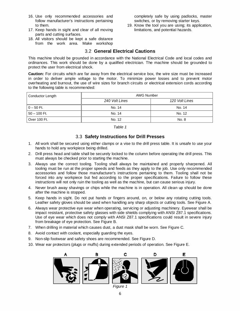
5. Keep hands in sight. Do not put hands or fingers around, on, or below any rotating cutting tools. Leather safety gloves should be used when handling any sharp objects or cutting tools. See Figure A.
6. Always wear protective eye wear when operating, servicing or adjusting machinery. Eyewear shall be impact resistant, protective safety glasses with side shields complying with ANSI Z87.1 specifications. Use of eye wear which does not comply with ANSI Z87.1 specifications could result in severe injury from breakage of eye protection. See Figure B.
7. When drilling in material which causes dust, a dust mask shall be worn. See Figure C. 8. Avoid contact with coolant, especially guarding the eyes. 9. Non-slip footwear and safety shoes are recommended. See Figure D. 10. Wear ear protectors (plugs or muffs) during extended periods of operation. See Figure E.
Figure 1
7
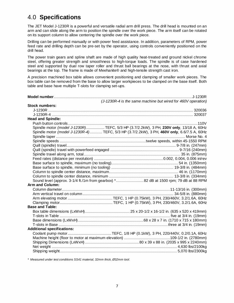
4.0 Specifications The JET Model J-1230R is a powerful and versatile radial arm drill press. The drill head is mounted on an arm and can slide along the arm to position the spindle over the work piece. The arm itself can be rotated on its support column to allow centering the spindle over the work piece.
Drilling can be performed manually or with power feed assistance. In addition, parameters of RPM, power feed rate and drilling depth can be pre-set by the operator, using controls conveniently positioned on the drill head.
The power train gears and spline shaft are made of high quality heat-treated and ground nickel chrome steel, offering greater strength and smoothness to high-torque loads. The spindle is of case hardened steel and supported by dual row taper roller and thrust ball bearings at the nose, with thrust and axial bearings at the top. The frame is made of Meehanite® and high-tensile strength cast iron.
A precision machined box table allows convenient positioning and clamping of smaller work pieces. The box table can be removed from the base to allow larger workpieces to be clamped on the base itself. Both table and base have multiple T-slots for clamping set-ups.
Model number ........................................................................................................................ J-1230R (J-1230R-4 is the same machine but wired for 460V operation) Stock numbers: J-1230R .............................................................................................................................. 320036 J-1230R-4 ........................................................................................................................... 320037 Head and Spindle: Push button controls ................................................................................................................. 110V Spindle motor (model J-1230R) ................ TEFC, 5/3 HP (3.7/2.2kW), 3 PH, 230V only, 13/18 A, 60Hz Spindle motor (model J-1230R-4) ........... TEFC, 5/3 HP (3.7/2.2kW), 3 PH, 460V only, 6.6/7.5 A, 60Hz Spindle taper ................................................................................................................ Morse No. 4 Spindle speeds ...........................................................................twelve speeds, within 45-1550 RPM Quill (spindle) travel............................................................................................... 9-7/8 in. (247mm) Quill (spindle) travel with powerfeed engaged ............................................................ 9-7/16 (240mm) Spindle travel along arm, total .................................................................................... 35 in. (875mm) Feed rates (distance per revolution) ............................................................ 0.002, 0.004, 0.006 in/rev Base surface to spindle, maximum (no tooling).......................................................... 54 in. (1350mm) Base surface to spindle, minimum (no tooling) ...................................................... 19-3/8 in. (484mm) Column to spindle center distance, maximum............................................................ 46 in. (1170mm) Column to spindle center distance, minimum ........................................................ 13-3/8 in. (334mm) Sound level (approx. 3-1/4 ft./1m from gearbox) * ........................ 82 dB at 1500 rpm; 79 dB at 88 RPM Arm and Column: Column diameter .............................................................................................. 11-13/16 in. (300mm) Arm vertical travel on column ............................................................................... 34-5/8 in. (880mm) Arm elevating motor ....................................... TEFC, 1 HP (0.75kW), 3 PH, 230/460V, 3.2/1.6A, 60Hz Clamping motor.............................................. TEFC, 1 HP (0.75kW), 3 PH, 230/460V, 3.2/1.6A, 60Hz Base and Table: Box table dimensions (LxWxH)....................................... 25 x 20-1/2 x 16-1/2 in. (635 x 520 x 419mm) T-slots in Table ................................................................................................ five at 3/4 in. (19mm) Base dimensions (LxWxH) .........................................................68 x 28 x 7 in. (1710 x 715 x 180mm) T-slots in Base ............................................................................................... three at 3/4 in. (19mm) Additional specifications: Coolant pump motor ...................................... TEFC, 1/8 HP (0.1kW), 3 PH, 220/440V, 0.2/0.1A, 60Hz Machine height (floor to motor at maximum elevation) ........................................ 109-1/2 in. (2780mm) Shipping Dimensions (LxWxH) ............................................... 80 x 39 x 88 in. (2035 x 995 x 2240mm) Net weight ............................................................................................................. 4,630 lbs/2100kg Shipping weight...................................................................................................... 5,070 lbs/2300kg * Measured under test conditions SS41 material, 32mm thick, Ø32mm tool.
8
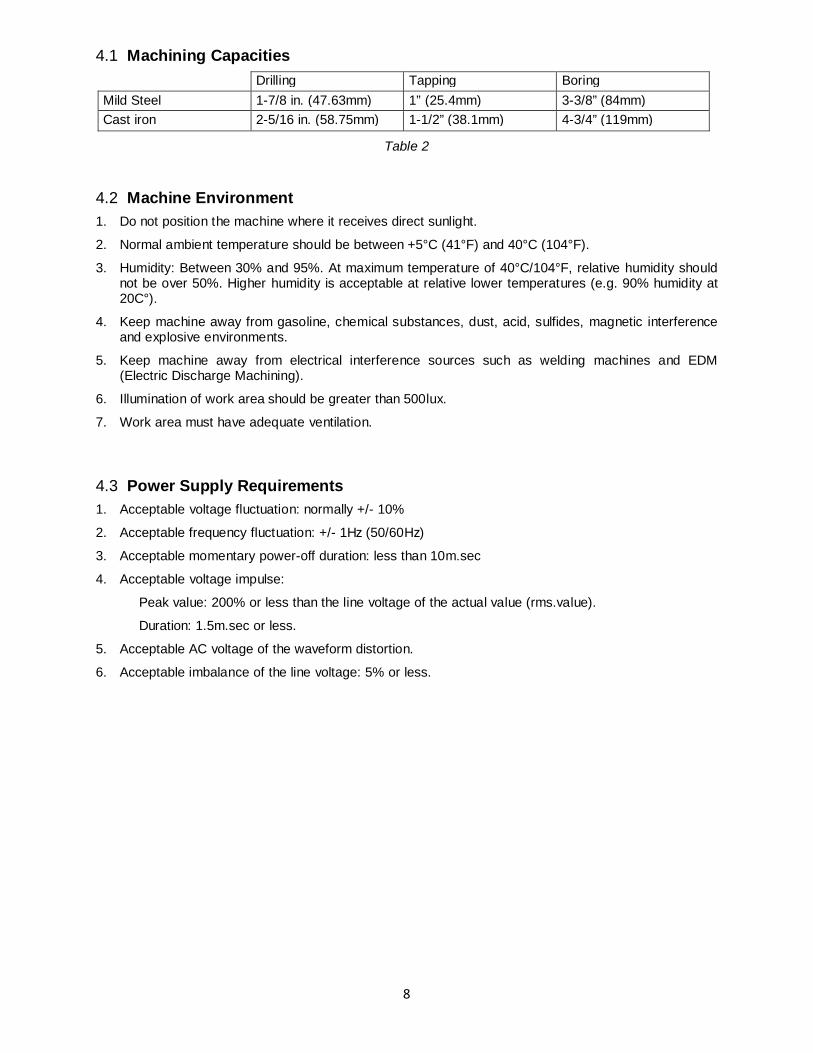
4.1 Machining Capacities Drilling Tapping Boring Mild Steel 1-7/8 in. (47.63mm) 1” (25.4mm) 3-3/8” (84mm) Cast iron 2-5/16 in. (58.75mm) 1-1/2” (38.1mm) 4-3/4” (119mm)
Table 2
4.2 Machine Environment 1. Do not position the machine where it receives direct sunlight.
2. Normal ambient temperature should be between +5°C (41°F) and 40°C (104°F).
3. Humidity: Between 30% and 95%. At maximum temperature of 40°C/104°F, relative humidity should not be over 50%. Higher humidity is acceptable at relative lower temperatures (e.g. 90% humidity at 20C°).
4. Keep machine away from gasoline, chemical substances, dust, acid, sulfides, magnetic interference and explosive environments.
5. Keep machine away from electrical interference sources such as welding machines and EDM (Electric Discharge Machining).
6. Illumination of work area should be greater than 500lux.
7. Work area must have adequate ventilation.
4.3 Power Supply Requirements 1. Acceptable voltage fluctuation: normally +/- 10%
2. Acceptable frequency fluctuation: +/- 1Hz (50/60Hz)
3. Acceptable momentary power-off duration: less than 10m.sec
4. Acceptable voltage impulse:
Peak value: 200% or less than the line voltage of the actual value (rms.value).
Duration: 1.5m.sec or less.
5. Acceptable AC voltage of the waveform distortion.
6. Acceptable imbalance of the line voltage: 5% or less.
9
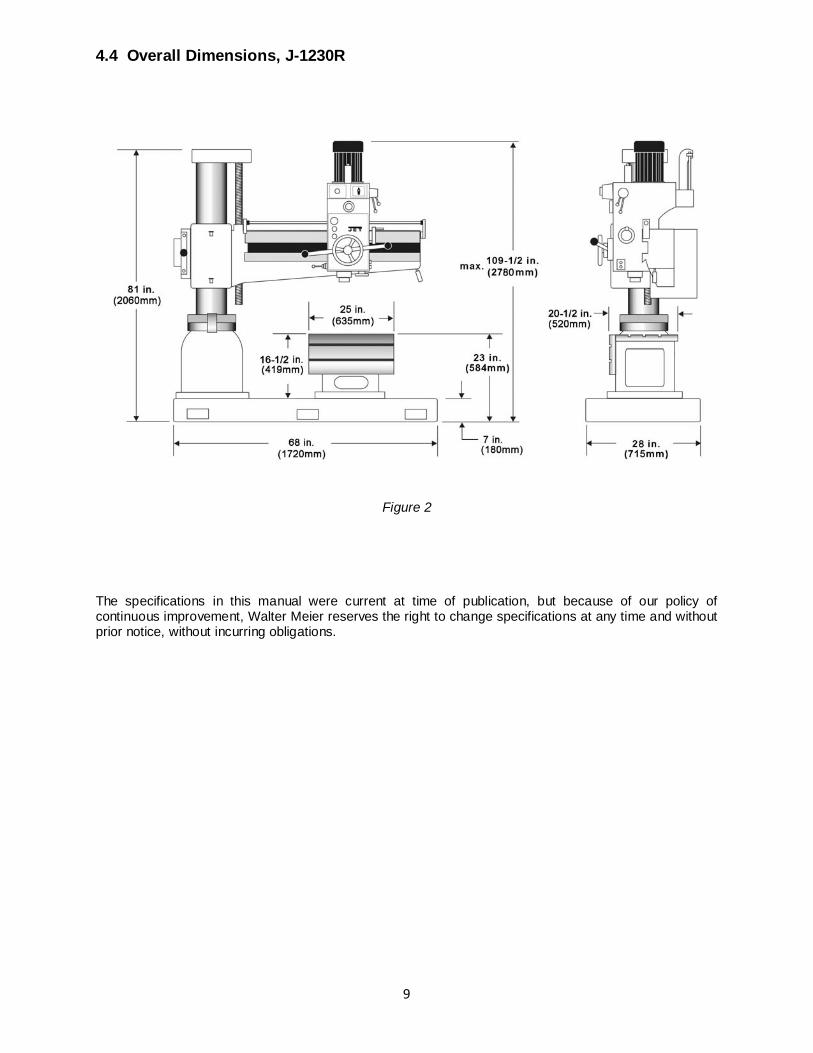
4.4 Overall Dimensions, J-1230R
Figure 2
The specifications in this manual were current at time of publication, but because of our policy of continuous improvement, Walter Meier reserves the right to change specifications at any time and without prior notice, without incurring obligations.
10
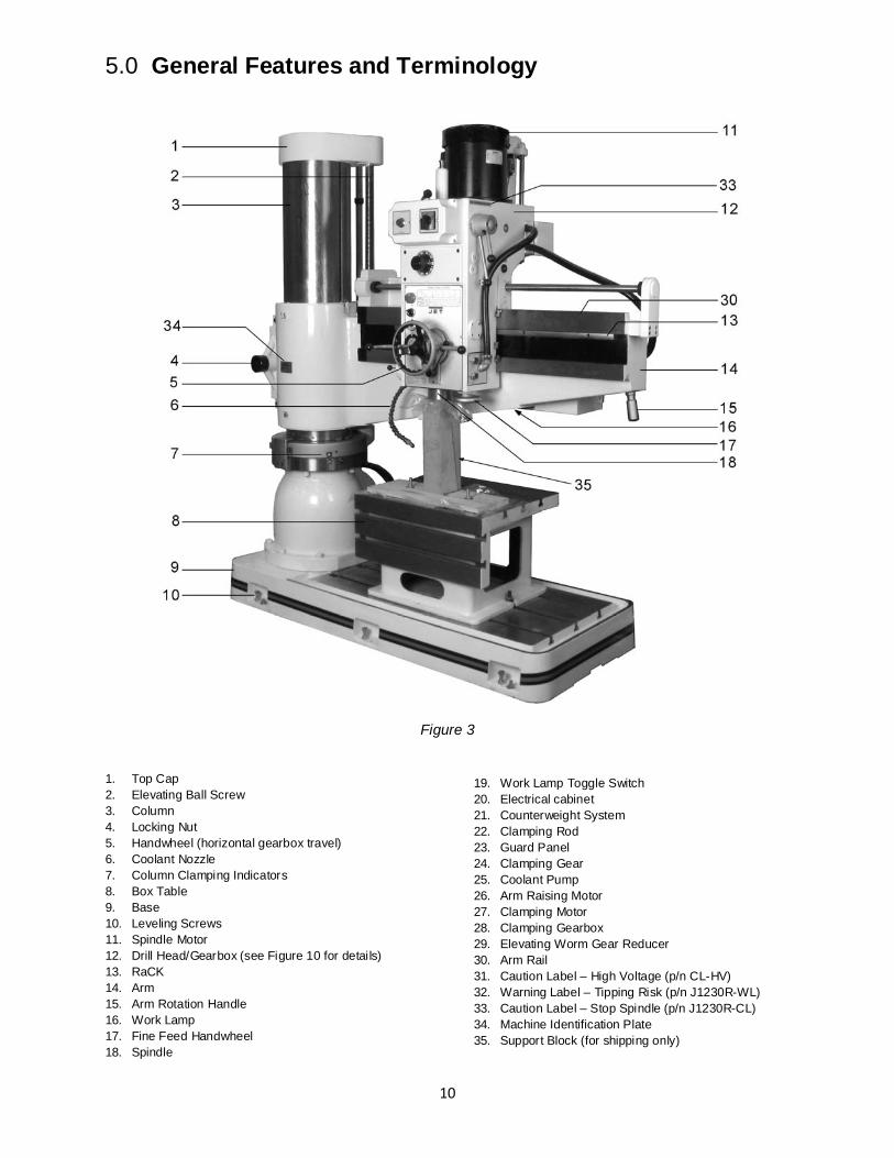
5.0 General Features and Terminology
Figure 3
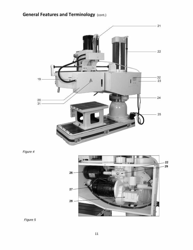
1. Top Cap 2. Elevating Ball Screw 3. Column 4. Locking Nut 5. Handwheel (horizontal gearbox travel) 6. Coolant Nozzle 7. Column Clamping Indicators 8. Box Table 9. Base 10. Leveling Screws 11. Spindle Motor 12. Drill Head/Gearbox (see Figure 10 for details) 13. RaCK 14. Arm 15. Arm Rotation Handle 16. Work Lamp 17. Fine Feed Handwheel 18. Spindle
19. Work Lamp Toggle Switch 20. Electrical cabinet 21. Counterweight System 22. Clamping Rod 23. Guard Panel 24. Clamping Gear 25. Coolant Pump 26. Arm Raising Motor 27. Clamping Motor 28. Clamping Gearbox 29. Elevating Worm Gear Reducer 30. Arm Rail 31. Caution Label – High Voltage (p/n CL-HV) 32. Warning Label – Tipping Risk (p/n J1230R-WL) 33. Caution Label – Stop Spindle (p/n J1230R-CL) 34. Machine Identification Plate 35. Support Block (for shipping only)
11
General Features and Terminology (cont.)
Figure 4
Figure 5
12
6.0 Set-Up and Assembly
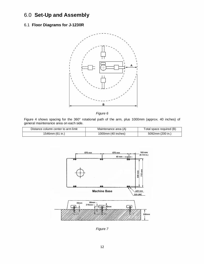
6.1 Floor Diagrams for J-1230R
Figure 6
Figure 4 shows spacing for the 360° rotational path of the arm, plus 1000mm (approx. 40 inches) of general maintenance area on each side.
Distance column center to arm limit Maintenance area (A) Total space required (B) 1546mm (61 in.) 1000mm (40 inches) 5092mm (200 in.)
Figure 7
13
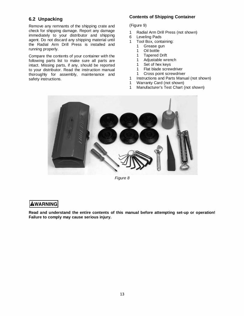
6.2 Unpacking Remove any remnants of the shipping crate and check for shipping damage. Report any damage immediately to your distributor and shipping agent. Do not discard any shipping material until the Radial Arm Drill Press is installed and running properly.
Compare the contents of your container with the following parts list to make sure all parts are intact. Missing parts, if any, should be reported to your distributor. Read the instruction manual thoroughly for assembly, maintenance and safety instructions.
Contents of Shipping Container
(Figure 9)
1 Radial Arm Drill Press (not shown) 6 Leveling Pads 1 Tool Box, containing:
1 Grease gun 1 Oil bottle 1 Tapered Drift 1 Adjustable wrench 1 Set of hex keys
1 Flat blade screwdriver 1 Cross point screwdriver 1 Instructions and Parts Manual (not shown) 1 Warranty Card (not shown) 1 Manufacturer’s Test Chart (not shown)
Figure 8
Read and understand the entire contents of this manual before attempting set-up or operation! Failure to comply may cause serious injury.
14
6.3 Machine Set-Up 1. After dismantling the crate, remove the
toolbox and any accessory items from around the machine.
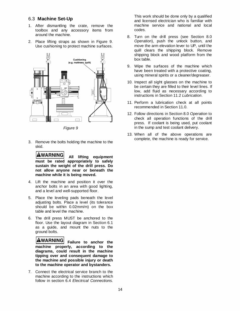
2. Place lifting straps as shown in Figure 9. Use cushioning to protect machine surfaces.
Figure 9
3. Remove the bolts holding the machine to the skid.
All lifting equipment must be rated appropriately to safely sustain the weight of the drill press. Do not allow anyone near or beneath the machine while it is being moved.
4. Lift the machine and position it over the anchor bolts in an area with good lighting, and a level and well-supported floor.
5. Place the leveling pads beneath the level adjusting bolts. Place a level (its tolerance should be within 0.02mm/m) on the box table and level the machine.
6. The drill press MUST be anchored to the floor. Use the layout diagram in Section 6.1 as a guide, and mount the nuts to the ground bolts.
Failure to anchor the machine properly, according to the diagrams, could result in the machine tipping over and consequent damage to the machine and possible injury or death to the machine operator and bystanders.
7. Connect the electrical service branch to the machine according to the instructions which follow in section 6.4 Electrical Connections.
This work should be done only by a qualified and licensed electrician who is familiar with machine service and national and local codes.
8. Turn on the drill press (see Section 8.0 Operation), push the unlock button, and move the arm elevation lever to UP, until the quill clears the shipping block. Remove shipping block and wood platform from the box table.
9. Wipe the surfaces of the machine which have been treated with a protective coating, using mineral spirits or a cleaner/degreaser.
10. Inspect all sight glasses on the machine to be certain they are filled to their level lines. If low, add fluid as necessary according to instructions in Section 11.2 Lubrication.
11. Perform a lubrication check at all points recommended in Section 11.0.
12. Follow directions in Section 8.0 Operation to check all operation functions of the drill press. If coolant is being used, put coolant in the sump and test coolant delivery.
13. When all of the above operations are complete, the machine is ready for service.
15
6.4 Electrical Connections
Electrical set-up should be performed only by a licensed electrician who is familiar with national and local electrical codes. This machine must be properly grounded to help prevent electrical shock and possible fatal injury.
Model J-1230R radial drills are tested before shipping, for all functions and circuits under electrical power specified for the machine and motors. The only hook-up requirement should be for correct connection to an appropriate cutout on an appropriate service branch.
Where the following instructions do not agree with local electrical codes and procedures, the applicable codes and procedures should be followed, exclusively.
Wiring diagram
A wiring diagram for the drill press is found inside the door of the electrical cabinet. It is also shown at the back of this manual. This diagram is for reference by your licensed installing or servicing electrician. In addition to using a licensed electrician for connection to the drill press service branch, the servicing of components and circuits inside the control box should be serviced only by a qualified electrician. This includes fuse replacement, if required. If any of these fuses, upon replacement, should continue to fail at short service intervals, the electrician should be asked to check all machine components for excessive loads, short circuits or other failures.
Electrical branch service
The machine is wired for either a 230V or 460V 3-phase service branch. The cable supplying the drill press will be tagged with the voltage at which the machine was tested and corresponding to the customer's order.
If the tag has been lost, it will be necessary for you to open the electrical cabinet on the rear of the drill press and examine the connections on the transformer found inside the box. The transformer can be connected to either a 230 or 460 volt source and its taps are labeled for voltage. By locating the source tap on the transformer you will be able to determine the branch voltage required.
A service disconnect is recommended. The use of fuses or circuit breakers for each of the voltage supply wires is required. Use fuses or circuit breakers which are appropriate to the voltage for the motor system delivered.
A positive cut-out/lock-out lever or rocker switch should be located on the outside of the service disconnect to allow the machine operator to disconnect from the branch circuit when working with tooling on the machine.
It is recommended that the 230 volt Drill Press be connected to a dedicated 25 amp circuit with a 25 amp circuit breaker or time delay fuse. Connect the 460 volt drill press to a dedicated 15 amp circuit with 15 amp circuit breaker or time delay fuse. Local codes take precedence over recommendations.
Connecting branch to drill press
1. Disconnect the service branch to the machine by moving the lever or rocker switch on the cutout box to OFF.
2. Connect the green wire (or green with white trace) to the branch ground.
3. Connect the remaining three wires in the cable (labeled R, S and T) to the three power lines in the branch.
4. Turn the power to the machine ON at the cutout box.
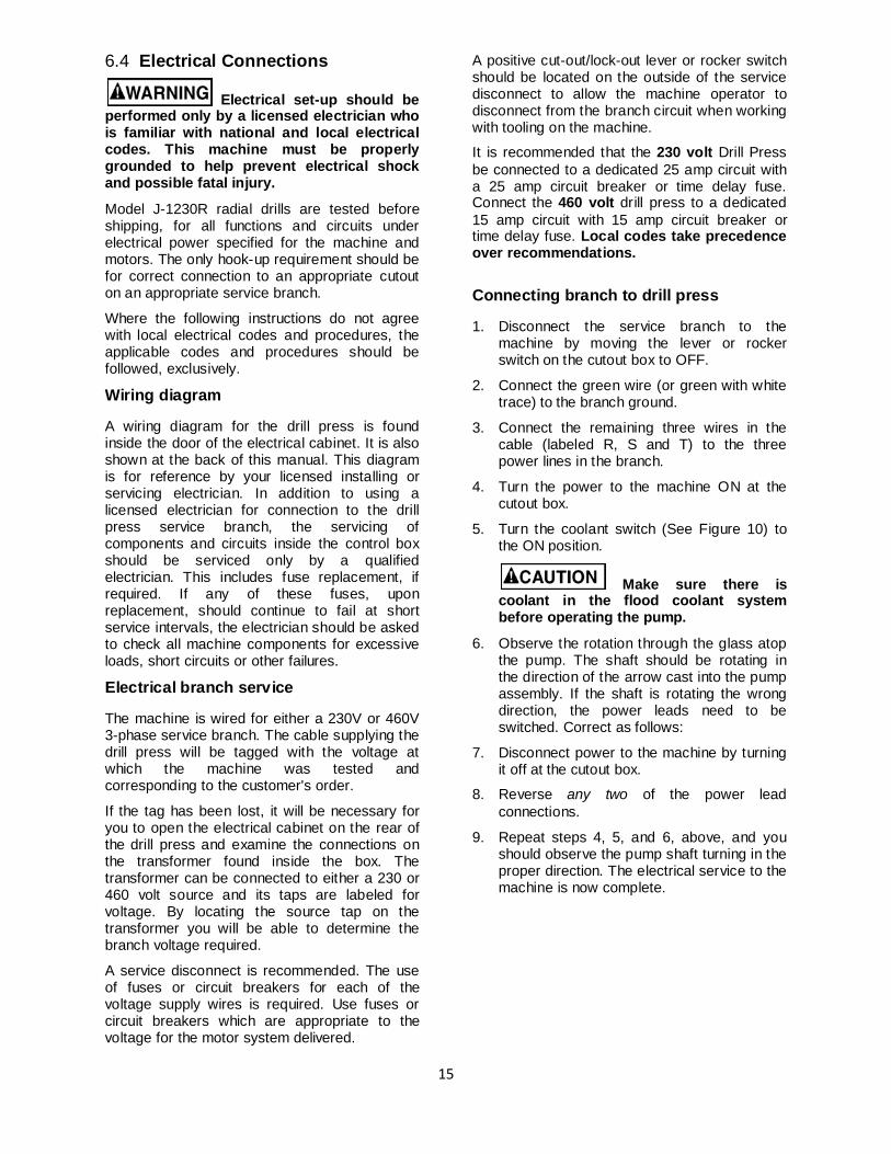
5. Turn the coolant switch (See Figure 10) to the ON position.
Make sure there is coolant in the flood coolant system before operating the pump.
6. Observe the rotation through the glass atop the pump. The shaft should be rotating in the direction of the arrow cast into the pump assembly. If the shaft is rotating the wrong direction, the power leads need to be switched. Correct as follows:
7. Disconnect power to the machine by turning it off at the cutout box.
8. Reverse any two of the power lead connections.
9. Repeat steps 4, 5, and 6, above, and you should observe the pump shaft turning in the proper direction. The electrical service to the machine is now complete.
16
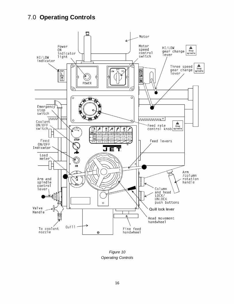
7.0 Operating Controls
Figure 10 Operating Controls
17
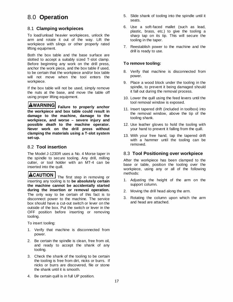
8.0 Operation
8.1 Clamping workpieces To load/unload heavier workpieces, unlock the arm and rotate it out of the way. Lift the workpiece with slings or other properly rated lifting equipment.
Both the box table and the base surface are slotted to accept a suitably sized T-slot clamp. Before beginning any work on the drill press, anchor the work piece, and the box table if used, to be certain that the workpiece and/or box table will not move when the tool enters the workpiece.
If the box table will not be used, simply remove the nuts at the base, and move the table off using proper lifting equipment.
Failure to properly anchor the workpiece and box table could result in damage to the machine, damage to the workpiece, and worse – severe injury and possible death to the machine operator. Never work on the drill press without clamping the materials using a T-slot system set-up.
8.2 Tool insertion The Model J-1230R uses a No. 4 Morse taper in the spindle to secure tooling. Any drill, milling cutter, or tool holder with an MT-4 can be inserted into the quill.
The first step in removing or inserting any tooling is to be absolutely certain the machine cannot be accidentally started during the insertion or removal operation. The only way to be certain of this fact is to disconnect power to the machine. The service box should have a cut-out switch or lever on the outside of the box. Put the switch or lever in the OFF position before inserting or removing tooling.
To insert tooling:
1. Verify that machine is disconnected from power.
2. Be certain the spindle is clean, free from oil, and ready to accept the shank of any tooling.
3. Check the shank of the tooling to be certain the tooling is free from dirt, nicks or burrs. If nicks or burrs are discovered, file or stone the shank until it is smooth.
4. Be certain quill is in full UP position.
5. Slide shank of tooling into the spindle until it seats.
6. Use a soft-faced mallet (such as lead, plastic, brass, etc.) to give the tooling a sharp tap on its tip. This will secure the tooling in the taper.
7. Reestablish power to the machine and the drill is ready to use.
To remove tooling:
8. Verify that machine is disconnected from power.
9. Place a wood block under the tooling in the spindle, to prevent it being damaged should it fall out during the removal process.
10. Lower the quill using the feed levers until the tool removal window is exposed.
11. Insert tapered drift (included in toolbox) into the removal window, above the tip of the tooling shank.
12. Use leather gloves to hold the tooling with your hand to prevent it falling from the quill.
13. With your free hand, tap the tapered drift with a hammer until the tooling can be removed.
8.3 Tool Positioning over workpiece After the workpiece has been clamped to the base or table, position the tooling over the workpiece, using any or all of the following methods:
1. Adjusting the height of the arm on the support column.
2. Moving the drill head along the arm.
3. Rotating the column upon which the arm and head are attached.
18
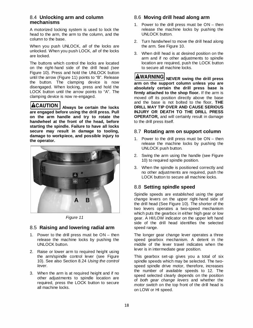
8.4 Unlocking arm and column mechanisms A motorized locking system is used to lock the head to the arm, the arm to the column, and the column to the base.
When you push UNLOCK, all of the locks are unlocked. When you push LOCK, all of the locks are locked.
The buttons which control the locks are located on the right-hand side of the drill head (see Figure 10). Press and hold the UNLOCK button until the arrow (Figure 11) points to “B”. Release the button. The clamping device is now disengaged. When locking, press and hold the LOCK button until the arrow points to “A”. The clamping device is now re-engaged.
Always be certain the locks are engaged before using the drill press. Pull on the arm handle and try to rotate the handwheel at the front of the head, before starting the spindle. Failure to have all locks secure may result in damage to tooling, damage to workpiece, and possible injury to the operator.
Figure 11
8.5 Raising and lowering radial arm 1. Power to the drill press must be ON – then
release the machine locks by pushing the UNLOCK button.
2. Raise or lower arm to required height using the arm/spindle control lever (see Figure 10). See also Section 8.24 Using the control lever.
3. When the arm is at required height and if no other adjustments to spindle location are required, press the LOCK button to secure all machine locks.
8.6 Moving drill head along arm 1. Power to the drill press must be ON – then
release the machine locks by pushing the UNLOCK button.
2. Turn handwheel to move the drill head along the arm. See Figure 10.
3. When drill head is at desired position on the arm and if no other adjustments to spindle location are required, push the LOCK button to secure all machine locks.
NEVER swing the drill press arm on the support column unless you are absolutely certain the drill press base is firmly attached to the shop floor. If the arm is moved off its position directly above the base and the base is not bolted to the floor, THE DRILL MAY TIP OVER AND CAUSE SERIOUS INJURY OR DEATH TO THE DRILL PRESS OPERATOR, and will certainly result in damage to the drill press itself.
8.7 Rotating arm on support column 1. Power to the drill press must be ON – then
release the machine locks by pushing the UNLOCK push button.
2. Swing the arm using the handle (see Figure 10) to required spindle position.
3. When the spindle is positioned correctly and no other adjustments are required, push the LOCK button to secure all machine locks.
8.8 Setting spindle speed Spindle speeds are established using the gear change levers on the upper right-hand side of the drill head (See Figure 10). The shorter of the two levers operates a two-speed mechanism which puts the gearbox in either high gear or low gear. A HI/LOW indicator on the upper left hand side of the drill head identifies the selected speed range.
The longer gear change lever operates a three speed gearbox mechanism. A detent in the middle of the lever travel indicates when the lever is in intermediate gear position.
This gearbox set-up gives you a total of six spindle speeds which may be selected. The two-speed spindle drive motor, therefore, increases the number of available speeds to 12. The speed selected clearly depends on the position of both gear change levers and whether the motor switch on the top front of the drill head is on LOW or HI speed.
19
A table on the front of the drill head shows gear change lever and motor switch values required to select each speed. A similar table is included in Section 10.0 of this manual.
On the gear change table you will also find the recommended drill sizes for the various speeds which are selectable. These recommendations are only approximate. With the wide variety of drill types and coatings available, as well as cutting fluids, and the even wider variety of work piece materials which you might be machining – you need to consult with your tooling, coolant and/or work piece suppliers to determine the best spindle speed to use for any specific drilling operation.
Do not try to change gears while the spindle is turning. This may cause serious damage to the spindle drive system.
Allow the spindle to stop completely before attempting to change gears. If the gear change lever you want to move does not slip easily into the new position, jog the motor for a second using the control lever. Then allow the spindle to come to a stop before attempting to change gears again. Repeat this jogging process, as necessary, until the gears match up properly for changing.
Plan for quill movement during high speed spindle rotation. High speed rotation without quill travel will increase spindle temperatures.
8.9 Feed rate and depth of cut The J-1230R has limit switches on the quill which cut power to the drive motor when the quill has reached either the upper or lower limit of its travel. This system is designed to prevent gearbox damage if the power feed mechanism is engaged – damage which would occur if the quill were to bottom out against the upper or lower limit of quill travel. In the event of failure of either limit switch there is also a safety clutch mechanism which will slip when travel limits are reached.
However, while you are able to use virtually the full travel of the quill for drilling or other operations, the drill press operator typically sets both the rate of feed (travel-per-revolution of the spindle), and the depth of cut (quill travel to make the required cut).
These two operations are described here:
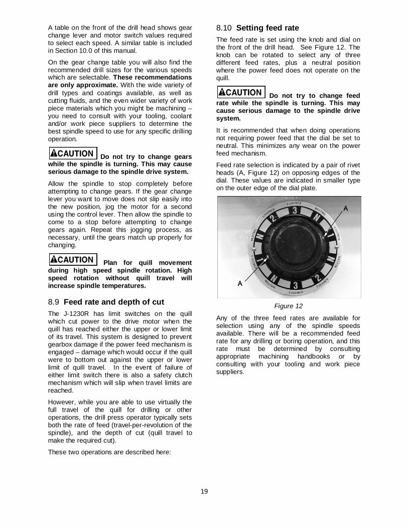
8.10 Setting feed rate The feed rate is set using the knob and dial on the front of the drill head. See Figure 12. The knob can be rotated to select any of three different feed rates, plus a neutral position where the power feed does not operate on the quill.
Do not try to change feed rate while the spindle is turning. This may cause serious damage to the spindle drive system.
It is recommended that when doing operations not requiring power feed that the dial be set to neutral. This minimizes any wear on the power feed mechanism.
Feed rate selection is indicated by a pair of rivet heads (A, Figure 12) on opposing edges of the dial. These values are indicated in smaller type on the outer edge of the dial plate.
Figure 12
Any of the three feed rates are available for selection using any of the spindle speeds available. There will be a recommended feed rate for any drilling or boring operation, and this rate must be determined by consulting appropriate machining handbooks or by consulting with your tooling and work piece suppliers.
20
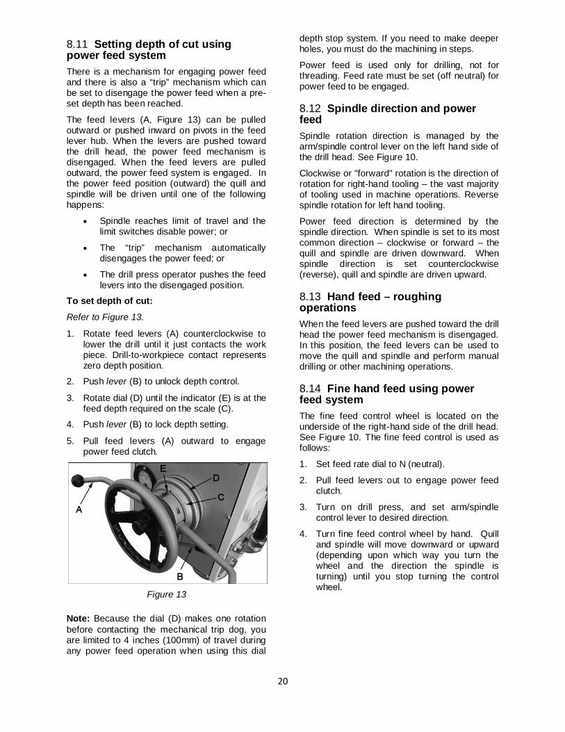
8.11 Setting depth of cut using power feed system There is a mechanism for engaging power feed and there is also a “trip” mechanism which can be set to disengage the power feed when a pre-set depth has been reached.
The feed levers (A, Figure 13) can be pulled outward or pushed inward on pivots in the feed lever hub. When the levers are pushed toward the drill head, the power feed mechanism is disengaged. When the feed levers are pulled outward, the power feed system is engaged. In the power feed position (outward) the quill and spindle will be driven until one of the following happens:
• Spindle reaches limit of travel and the limit switches disable power; or
• The “trip” mechanism automatically disengages the power feed; or
• The drill press operator pushes the feed levers into the disengaged position.
To set depth of cut:
Refer to Figure 13.
1. Rotate feed levers (A) counterclockwise to lower the drill until it just contacts the work piece. Drill-to-workpiece contact represents zero depth position.
2. Push lever (B) to unlock depth control.
3. Rotate dial (D) until the indicator (E) is at the feed depth required on the scale (C).
4. Push lever (B) to lock depth setting.
5. Pull feed levers (A) outward to engage power feed clutch.
Figure 13
Note: Because the dial (D) makes one rotation before contacting the mechanical trip dog, you are limited to 4 inches (100mm) of travel during any power feed operation when using this dial
depth stop system. If you need to make deeper holes, you must do the machining in steps.
Power feed is used only for drilling, not for threading. Feed rate must be set (off neutral) for power feed to be engaged.
8.12 Spindle direction and power feed Spindle rotation direction is managed by the arm/spindle control lever on the left hand side of the drill head. See Figure 10.
Clockwise or "forward" rotation is the direction of rotation for right-hand tooling – the vast majority of tooling used in machine operations. Reverse spindle rotation for left hand tooling.
Power feed direction is determined by the spindle direction. When spindle is set to its most common direction – clockwise or forward – the quill and spindle are driven downward. When spindle direction is set counterclockwise (reverse), quill and spindle are driven upward.
8.13 Hand feed – roughing operations When the feed levers are pushed toward the drill head the power feed mechanism is disengaged. In this position, the feed levers can be used to move the quill and spindle and perform manual drilling or other machining operations.
8.14 Fine hand feed using power feed system The fine feed control wheel is located on the underside of the right-hand side of the drill head. See Figure 10. The fine feed control is used as follows:
1. Set feed rate dial to N (neutral).
2. Pull feed levers out to engage power feed clutch.
3. Turn on drill press, and set arm/spindle control lever to desired direction.
4. Turn fine feed control wheel by hand. Quill and spindle will move downward or upward (depending upon which way you turn the wheel and the direction the spindle is turning) until you stop turning the control wheel.
21
8.15 Tapping 1. Insert screw tap into spindle.
2. Move spindle into position.
3. Set spindle control to Forward.
4. Rotate the feed levers counterclockwise until desired tapping depth is reached.
5. Reverse spindle direction and allow tap to withdraw completely from workpiece.
6. Stop spindle by moving spindle control switch to center.
8.16 Power ON/OFF If your J-1230R was connected to its service branch correctly, there will be a service disconnect with an external power cutoff lever or switch which disconnects the drill press from the service branch. This is your ultimate protection against accidental machine start-up when clamping work pieces or inserting and removing tooling. Always be certain you have turned off power at this disconnect before beginning such procedures.
8.17 Power ON light When the cutout box power is ON, the red POWER light on the upper left hand side of the drill head (Figure 10) will be lit. In this mode, power to the coolant pump and to the spindle drive motor is controlled by the switches on the control console.
8.18 Coolant control The flood coolant system is controlled by the dial on the front of the gearbox (Figure 10). If coolant has been turned on, but does not flow, check the pump rotation by observing the pump shaft. It should be rotating in the direction of the arrow on the pump casting. If rotation is incorrect, see Section 6.4 Electrical Connections, for more information.
Open the valve to the coolant nozzle using the handle at the left of the head (see Figure 10).The proximity of the nozzle can be adjusted by loosening the two knobs and sliding the coolant pipe up or down as needed. Retighten knobs.
8.19 Spindle motor controls Power to spindle motor is controlled as follows:
1. The cutout box control lever must be in the ON position.
2. The motor speed control switch must be in either HI or LOW position.
3. The Emergency Stop switch must be disengaged.
4. The arm/spindle control lever must be engaged for selected rotation. See Section 8.24 Arm/spindle control lever.
8.20 Turning off spindle drive To turn power OFF on the spindle drive motor do one of the following:
1. Put the two speed motor switch in OFF position, OR...
2. Put arm/spindle control lever in neutral, OR...
3. Push red STOP switch, OR...
4. When servicing the tooling or other machine components, put the service disconnect lever in OFF position.
Once the STOP switch has been pushed (step 3 above) none of the other switches on the panel can be used to control power to the spindle drive motor or coolant pump until the STOP switch has been reset.
8.21 Resetting STOP switch Turn the Stop switch clockwise in the direction of the arrow on the red button. The switch is re-set and the other spindle motor controls can be used.
8.22 Using load ammeter An ammeter on the control console is used to monitor the load on the spindle drive motor. It is connected into one of the three power lines which supply the main drive motor.
When the drive motor is ON and up to speed, and there is no tooling being used to drill, tap or bore a hole, the ammeter should read approximately 2.5 amps. If it exceeds this value there is a problem internally (such as lack of lubrication in the gearboxes, bad bearings, etc.). You should turn off the machine and determine the cause of any excessive free-running load.
Monitor the ammeter during machining operations. The ammeter should stay below 9 amps of current draw during machining. You should adjust spindle speed, feed rate and coolant use to maintain full load current draw below the 9 amp value.
22
If you exceed 9 amps current draw a thermal overload switch in the electrical control panel will trip. If this occurs, locate and reset the thermal switch.
8.23 Tapping operations 1. Determine the most efficient tapping speed
(spindle speed) by consulting appropriate machinist's tables, your tap supplier, coolant supplier and/or workpiece supplier.
2. Be certain that feed rate dial is at neutral. See Section 8.10 Setting feed rate.
3. Turn on spindle motor. Also, turn on the coolant pump if coolant is being used.
4. Move arm/spindle control lever to Forward.
5. Use the feed levers to move the tap into its pilot hole until the tap makes its initial thread cut and is engaged in the work piece.
6. Allow the tap to "self feed" into the pilot hole until it has completed its tapping operation.
7. Move arm/spindle control lever to neutral and allow spindle to stop completely.
8. Move arm/spindle control lever to reverse, so that tap unscrews itself from the hole it has just threaded.
8.24 Arm/spindle control lever The four-position arm/spindle control lever is located on the left hand side of the drill head console. See Figure 10. It controls spindle rotation direction and raising and lowering of the arm.
The ability to control the height of the arm is available when:
1. The main power to the machine is ON at its branch service panel.
2. The emergency STOP switch is disengaged.
3. The arm/spindle control lever is pushed up or down.
4. The column and arm UNLOCK button (right hand side of the drill head – see Figure 10) is pressed to disengage the machine locks.
NOTE: The control lever does not return to neutral when released, but remains in position. This means unless you return it to neutral, the arm will keep raising or lowering until it contacts a limit switch.
9.0 Adjustments After extended use – usually several years – the radial arm drill may require adjustment of certain parts. Two areas require particular attention:
• The clamping device. • The gap between head and rail.
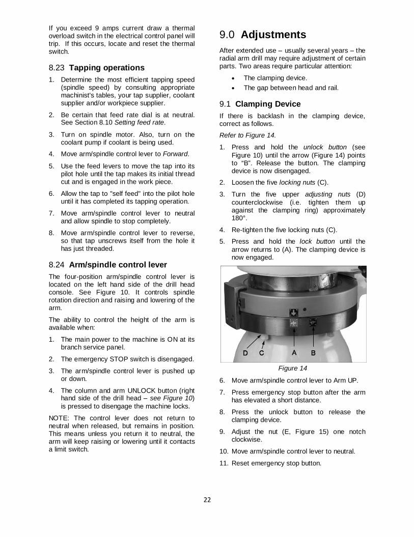
9.1 Clamping Device If there is backlash in the clamping device, correct as follows.
Refer to Figure 14.
1. Press and hold the unlock button (see Figure 10) until the arrow (Figure 14) points to “B”. Release the button. The clamping device is now disengaged.
2. Loosen the five locking nuts (C).
3. Turn the five upper adjusting nuts (D) counterclockwise (i.e. tighten them up against the clamping ring) approximately 180°.
4. Re-tighten the five locking nuts (C).
5. Press and hold the lock button until the arrow returns to (A). The clamping device is now engaged.
Figure 14
6. Move arm/spindle control lever to Arm UP.
7. Press emergency stop button after the arm has elevated a short distance.
8. Press the unlock button to release the clamping device.
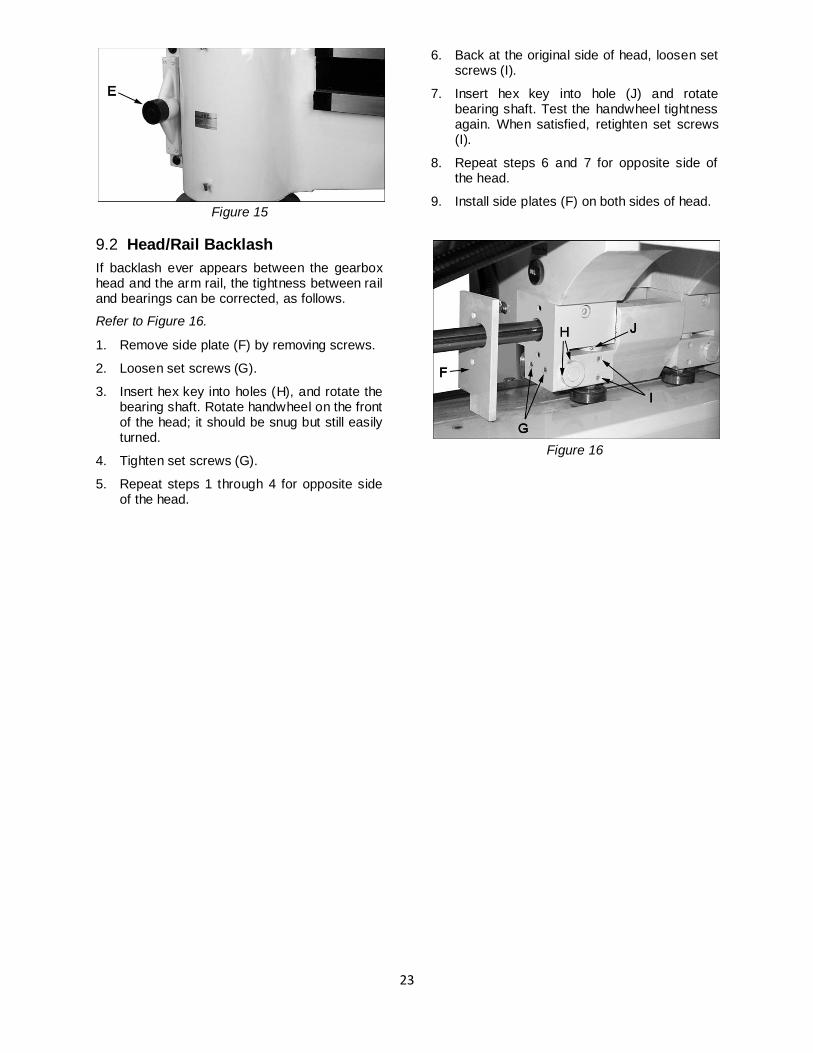
9. Adjust the nut (E, Figure 15) one notch clockwise.
10. Move arm/spindle control lever to neutral.
11. Reset emergency stop button.
23
Figure 15
9.2 Head/Rail Backlash If backlash ever appears between the gearbox head and the arm rail, the tightness between rail and bearings can be corrected, as follows.
Refer to Figure 16.
1. Remove side plate (F) by removing screws.
2. Loosen set screws (G).
3. Insert hex key into holes (H), and rotate the bearing shaft. Rotate handwheel on the front of the head; it should be snug but still easily turned.
4. Tighten set screws (G).
5. Repeat steps 1 through 4 for opposite side of the head.
6. Back at the original side of head, loosen set screws (I).
7. Insert hex key into hole (J) and rotate bearing shaft. Test the handwheel tightness again. When satisfied, retighten set screws (I).
8. Repeat steps 6 and 7 for opposite side of the head.
9. Install side plates (F) on both sides of head.
Figure 16
24
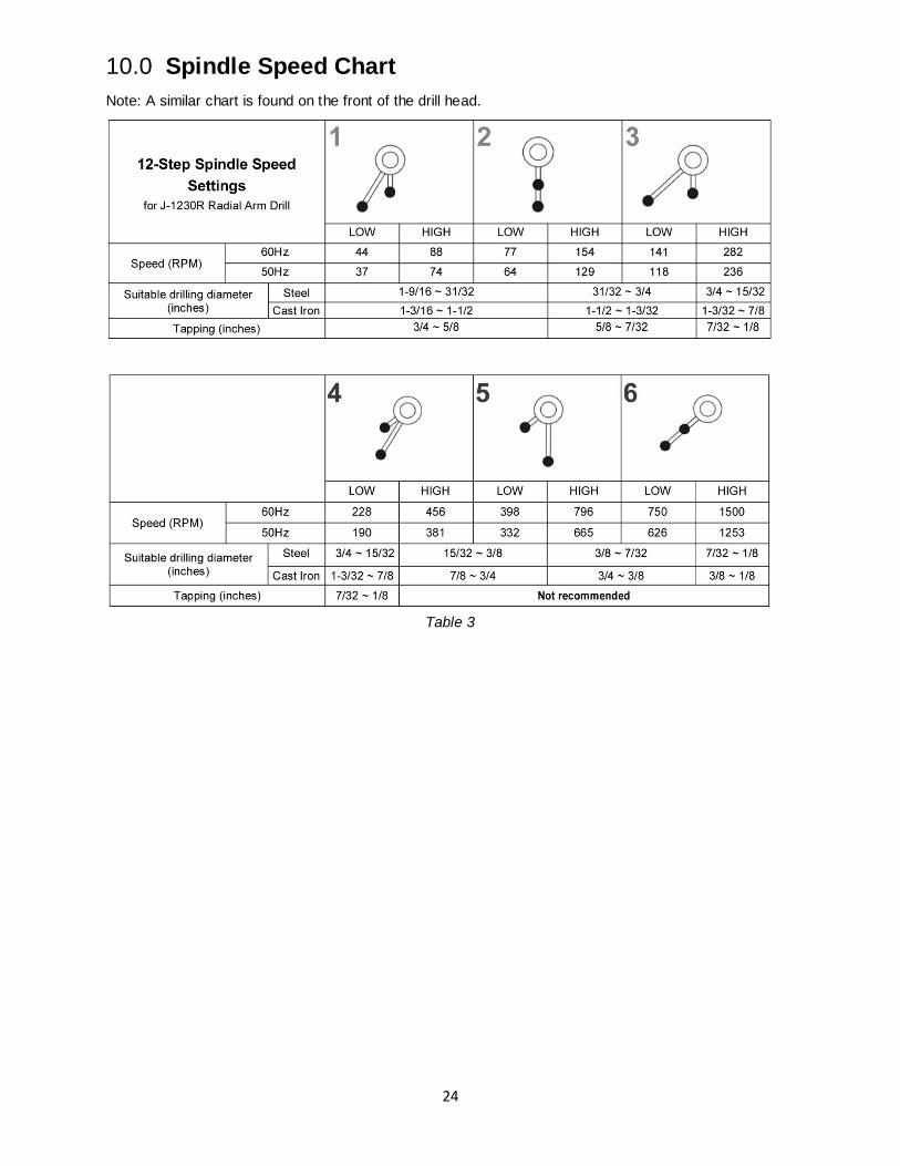
10.0 Spindle Speed Chart Note: A similar chart is found on the front of the drill head.
Table 3
25
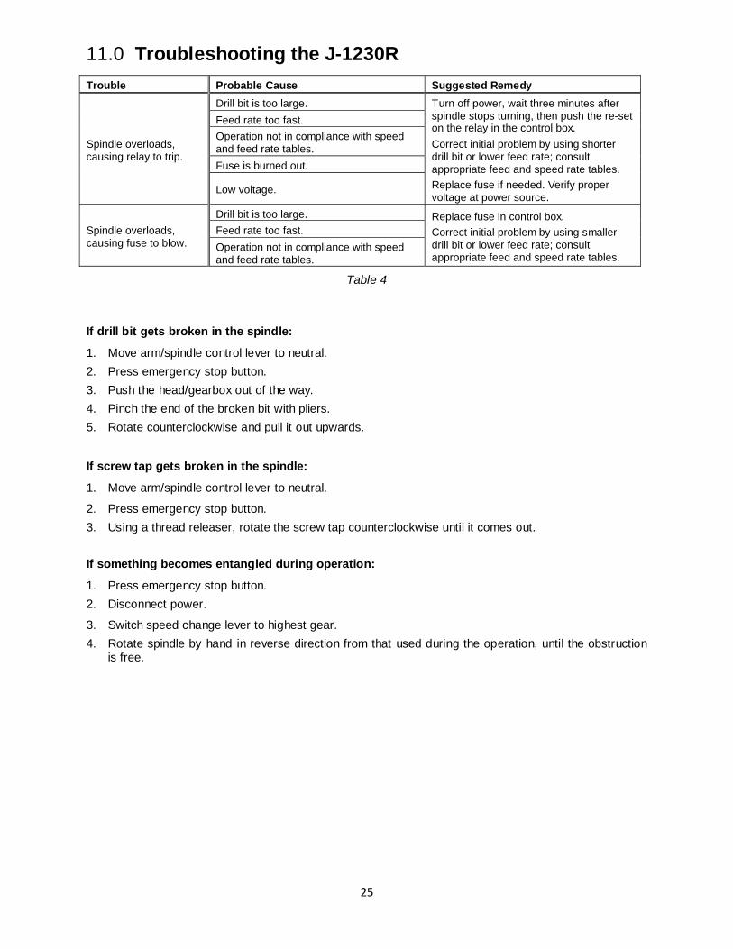
11.0 Troubleshooting the J-1230R Trouble Probable Cause Suggested Remedy
Spindle overloads, causing relay to trip.
Drill bit is too large. Turn off power, wait three minutes after spindle stops turning, then push the re-set on the relay in the control box. Correct initial problem by using shorter drill bit or lower feed rate; consult appropriate feed and speed rate tables. Replace fuse if needed. Verify proper voltage at power source.
Feed rate too fast. Operation not in compliance with speed and feed rate tables. Fuse is burned out.
Low voltage.
Spindle overloads, causing fuse to blow.
Drill bit is too large. Replace fuse in control box. Correct initial problem by using smaller drill bit or lower feed rate; consult appropriate feed and speed rate tables.
Feed rate too fast. Operation not in compliance with speed and feed rate tables.
Table 4
If drill bit gets broken in the spindle:
1. Move arm/spindle control lever to neutral. 2. Press emergency stop button. 3. Push the head/gearbox out of the way. 4. Pinch the end of the broken bit with pliers. 5. Rotate counterclockwise and pull it out upwards.
If screw tap gets broken in the spindle:
1. Move arm/spindle control lever to neutral.
2. Press emergency stop button. 3. Using a thread releaser, rotate the screw tap counterclockwise until it comes out.
If something becomes entangled during operation:
1. Press emergency stop button. 2. Disconnect power.
3. Switch speed change lever to highest gear. 4. Rotate spindle by hand in reverse direction from that used during the operation, until the obstruction
is free.
26
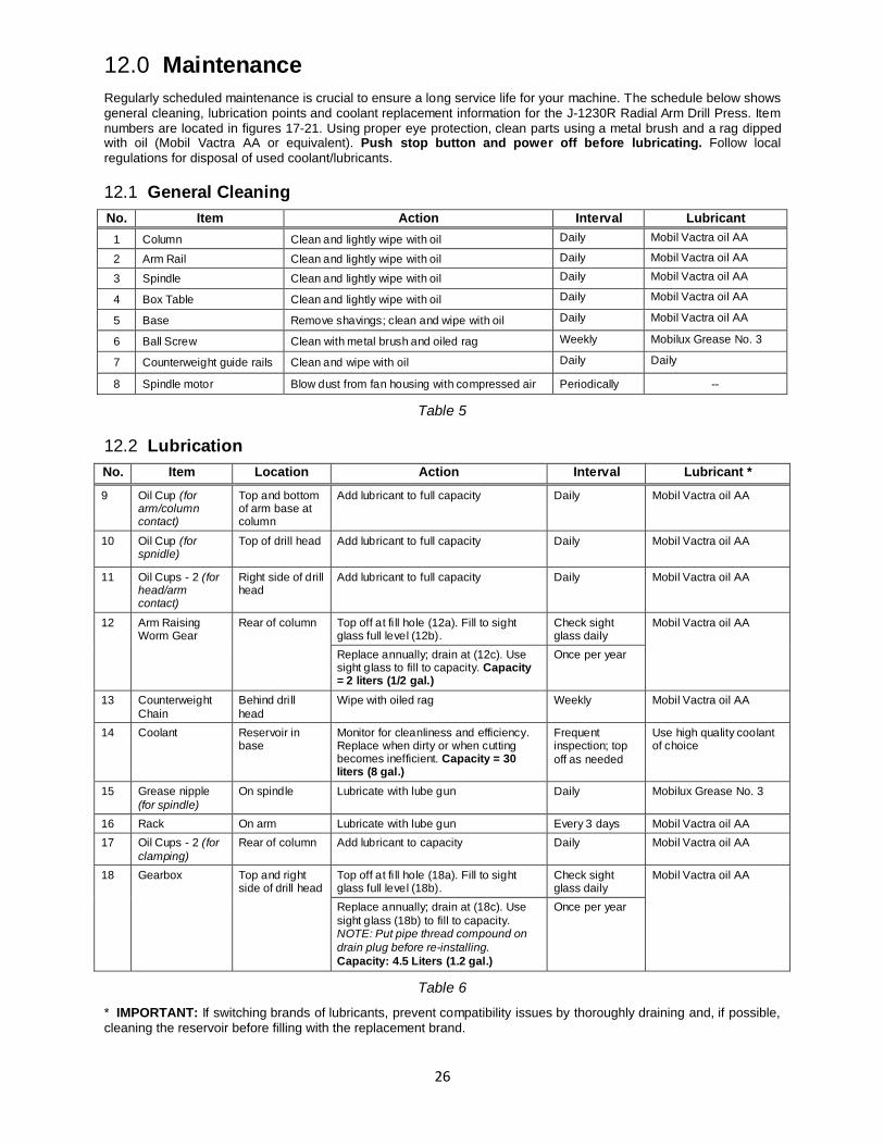
12.0 Maintenance Regularly scheduled maintenance is crucial to ensure a long service life for your machine. The schedule below shows general cleaning, lubrication points and coolant replacement information for the J-1230R Radial Arm Drill Press. Item numbers are located in figures 17-21. Using proper eye protection, clean parts using a metal brush and a rag dipped with oil (Mobil Vactra AA or equivalent). Push stop button and power off before lubricating. Follow local regulations for disposal of used coolant/lubricants.
12.1 General Cleaning No. Item Action Interval Lubricant
1 Column Clean and lightly wipe with oil Daily Mobil Vactra oil AA
2 Arm Rail Clean and lightly wipe with oil Daily Mobil Vactra oil AA
3 Spindle Clean and lightly wipe with oil Daily Mobil Vactra oil AA
4 Box Table Clean and lightly wipe with oil Daily Mobil Vactra oil AA
5 Base Remove shavings; clean and wipe with oil Daily Mobil Vactra oil AA
6 Ball Screw Clean with metal brush and oiled rag Weekly Mobilux Grease No. 3
7 Counterweight guide rails Clean and wipe with oil Daily Daily
8 Spindle motor Blow dust from fan housing with compressed air Periodically --
Table 5
12.2 Lubrication No. Item Location Action Interval Lubricant *
9 Oil Cup (for arm/column contact)
Top and bottom of arm base at column
Add lubricant to full capacity Daily Mobil Vactra oil AA
10 Oil Cup (for spnidle)
Top of drill head Add lubricant to full capacity Daily Mobil Vactra oil AA
11 Oil Cups - 2 (for head/arm contact)
Right side of drill head
Add lubricant to full capacity Daily Mobil Vactra oil AA
12 Arm Raising Worm Gear
Rear of column Top off at fi ll hole (12a). Fill to sight glass full level (12b).
Check sight glass daily
Mobil Vactra oil AA
Replace annually; drain at (12c). Use sight glass to fill to capacity. Capacity = 2 liters (1/2 gal.)
Once per year
13 Counterweight Chain
Behind dri ll head
Wipe with oiled rag Weekly Mobil Vactra oil AA
14 Coolant Reservoir in base
Monitor for cleanliness and efficiency. Replace when dirty or when cutting becomes inefficient. Capacity = 30 liters (8 gal.)
Frequent inspection; top off as needed
Use high quality coolant of choice
15 Grease nipple (for spindle)
On spindle Lubricate with lube gun Daily Mobilux Grease No. 3
16 Rack On arm Lubricate with lube gun Every 3 days Mobil Vactra oil AA
17 Oil Cups - 2 (for clamping)
Rear of column Add lubricant to capacity Daily Mobil Vactra oil AA
18 Gearbox Top and right side of drill head
Top off at fi ll hole (18a). Fill to sight glass full level (18b).
Check sight glass daily
Mobil Vactra oil AA
Replace annually; drain at (18c). Use sight glass (18b) to fill to capacity. NOTE: Put pipe thread compound on drain plug before re-installing. Capacity: 4.5 Liters (1.2 gal.)
Once per year
Table 6
* IMPORTANT: If switching brands of lubricants, prevent compatibility issues by thoroughly draining and, if possible, cleaning the reservoir before filling with the replacement brand.
27
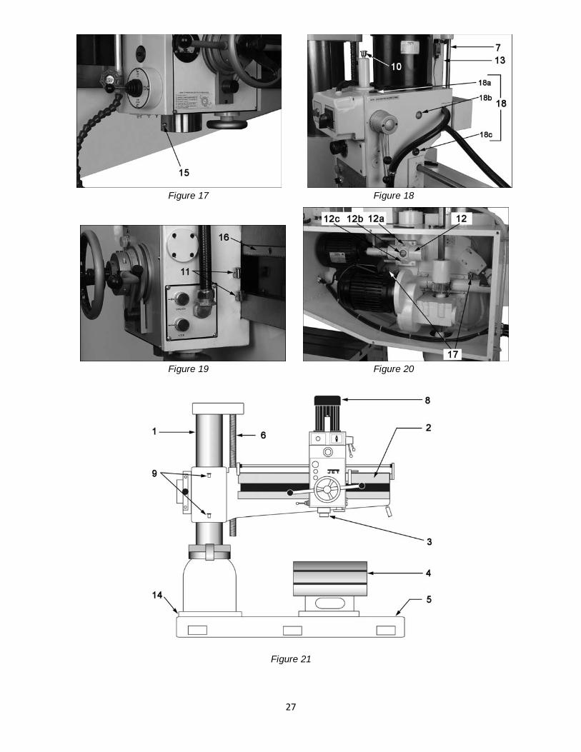
Figure 17 Figure 18
Figure 19 Figure 20
Figure 21
28
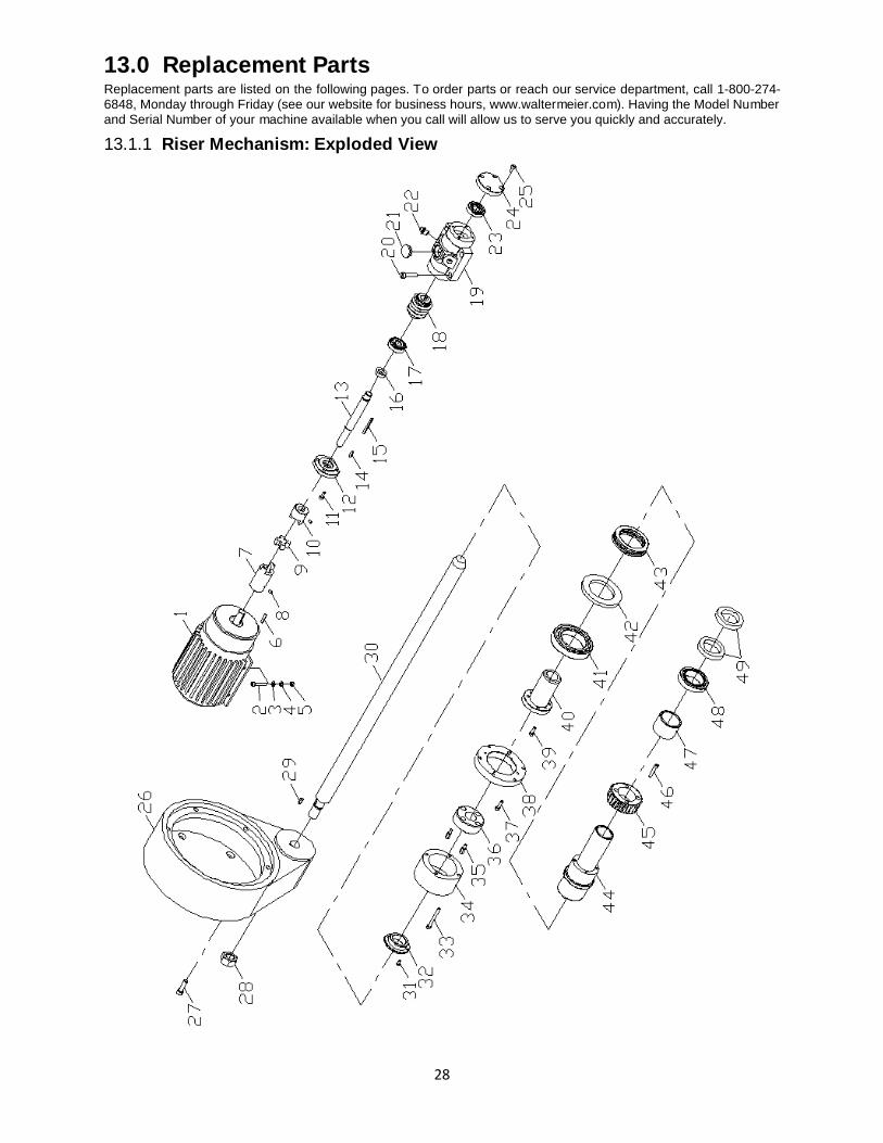
13.0 Replacement Parts Replacement parts are listed on the following pages. To order parts or reach our service department, call 1-800-274-6848, Monday through Friday (see our website for business hours, www.waltermeier.com). Having the Model Number and Serial Number of your machine available when you call will allow us to serve you quickly and accurately.
13.1.1 Riser Mechanism: Exploded View
29
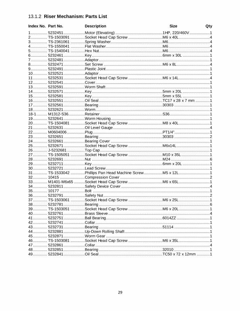
13.1.2 Riser Mechanism: Parts List
Index No. Part No. Description Size Qty 1 .............. 5232451 ..................Motor (Elevating) ........................................1HP, 220/460V ................. 1 2 .............. TS-1503091 ............Socket Head Cap Screw .............................M6 x 40L .......................... 4 3 .............. TS-2361061 ............Spring Washer............................................M6 ................................... 4 4 .............. TS-1550041 ............Flat Washer................................................M6 ................................... 4 5 .............. TS-1540041 ............Hex Nut......................................................M6 ................................... 4 6 .............. 5232461 ..................Key ............................................................6mm x 30L ....................... 1 7 .............. 5232481 ..................Adaptor .............................................................................................. 1 8 .............. 5232471 ..................Set Screw ..................................................M6 x 8L ............................ 4 9 .............. 5232491 ..................Plastic Joint ........................................................................................ 1 10 ............ 5232521 ..................Adaptor .............................................................................................. 1 11 ............ 5232531 ..................Socket Head Cap Screw .............................M6 x 14L .......................... 4 12 ............ 5232541 ..................Cover ................................................................................................. 1 13 ............ 5232591 ..................Worm Shaft ........................................................................................ 1 14 ............ 5232571 ..................Key ............................................................5mm x 20L ....................... 1 15 ............ 5232581 ..................Key ............................................................5mm x 55L ....................... 1 16 ............ 5232551 ..................Oil Seal ......................................................TC17 x 28 x 7 mm ............ 1 17 ............ 5232561 ..................Bearing ......................................................30303 .............................. 1 18 ............ 5232621 ..................Worm ................................................................................................. 1 18-1 ......... M1312-S36..............Retainer .....................................................S36.................................. 1 19 ............ 5232641 ..................Worm Housing.................................................................................... 1 20 ............ TS-1504081 ............Socket Head Cap Screw .............................M8 x 40L .......................... 1 21 ............ 5232631 ..................Oil Level Gauge .................................................................................. 4 22 ............ M0604006 ...............Plug ...........................................................PT1/4”.............................. 1 23 ............ 5232651 ..................Bearing ......................................................30303 .............................. 2 24 ............ 5232661 ..................Bearing Cover .................................................................................... 1 25 ............ 5232671 ..................Socket Head Cap Screw .............................M6x14L ............................ 1 26 ............ J-5232681 ...............Top Cap ............................................................................................. 1 27 ............ TS-1505051 ............Socket Head Cap Screw .............................M10 x 35L ........................ 1 28 ............ 5232691 ..................Nut ............................................................M24 ................................. 6 29 ............ 5232711 ..................Key ............................................................6mm x 20L ....................... 1 30 ............ 5232721 ..................Lead Screw ........................................................................................ 1 31 ............ TS-1533042 ............Phillips Pan Head Machine Screw................M5 x 12L .......................... 1 32 ............ 10415 .....................Compression Cover ............................................................................ 2 33 ............ M1401-M6x65 .........Socket Head Cap Screw .............................M6 x 65L .......................... 1 34 ............ 5232811 ..................Safety Device Cover ........................................................................... 4 35 ............ 10177 .....................Bolt ................................................................................................... 1 36 ............ 5232791 ..................Safety Nut .......................................................................................... 2 37 ............ TS-1503061 ............Socket Head Cap Screw .............................M6 x 25L .......................... 1 38 ............ 5232781 ..................Bearing .............................................................................................. 6 39 ............ TS-1503051 ............Socket Head Cap Screw .............................M6 x 20L .......................... 1 40 ............ 5232761 ..................Brass Sleeve ...................................................................................... 4 41 ............ 5232751 ..................Ball Bearing................................................6014ZZ ............................ 1 42 ............ 5232741 ..................Collar ................................................................................................. 1 43 ............ 5232731 ..................Bearing ......................................................51114 .............................. 1 44 ............ 5232881 ..................Up-Down Rolling Shaft ........................................................................ 1 45 ............ 5232871 ..................Worm Gear ........................................................................................ 1 46 ............ TS-1503081 ............Socket Head Cap Screw .............................M6 x 35L .......................... 1 47 ............ 5232861 ..................Collar ................................................................................................. 4 48 ............ 5232851 ..................Bearing ......................................................32010 .............................. 1 49 ............ 5232841 ..................Oil Seal ......................................................TC50 x 72 x 12mm ........... 1
30
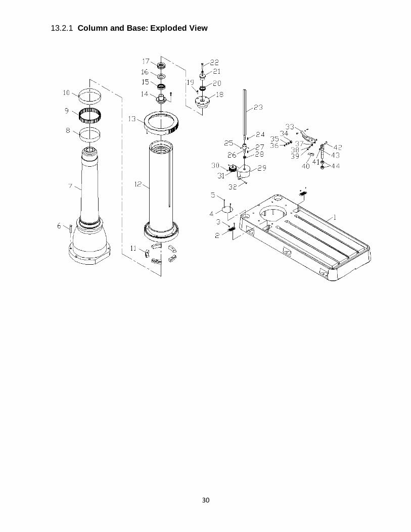
13.2.1 Column and Base: Exploded View
31
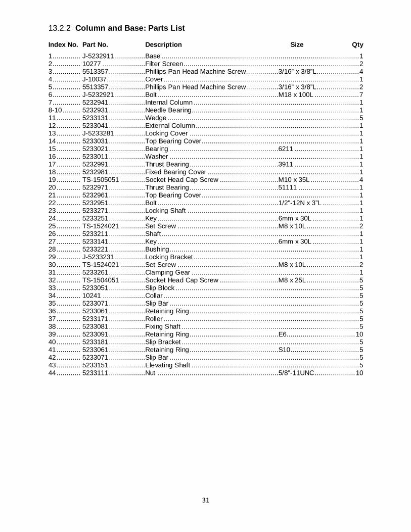
13.2.2 Column and Base: Parts List
Index No. Part No. Description Size Qty 1 .............. J-5232911 ...............Base .................................................................................................. 1 2 .............. 10277 .....................Filter Screen ....................................................................................... 2 3 .............. 5513357 ..................Phillips Pan Head Machine Screw................3/16” x 3/8”L ..................... 4 4 .............. J-10037 ...................Cover ................................................................................................. 1 5 .............. 5513357 ..................Phillips Pan Head Machine Screw................3/16” x 3/8”L ..................... 2 6 .............. J-5232921 ...............Bolt ............................................................M18 x 100L ...................... 7 7 .............. 5232941 ..................Internal Column .................................................................................. 1 8-10 ......... 5232931 ..................Needle Bearing................................................................................... 1 11 ............ 5233131 ..................Wedge ............................................................................................... 5 12 ............ 5233041 ..................External Column ................................................................................. 1 13 ............ J-5233281 ...............Locking Cover .................................................................................... 1 14 ............ 5233031 ..................Top Bearing Cover.............................................................................. 1 15 ............ 5233021 ..................Bearing ......................................................6211 ................................ 1 16 ............ 5233011 ..................Washer .............................................................................................. 1 17 ............ 5232991 ..................Thrust Bearing ............................................3911 ................................ 1 18 ............ 5232981 ..................Fixed Bearing Cover ........................................................................... 1 19 ............ TS-1505051 ............Socket Head Cap Screw .............................M10 x 35L ........................ 4 20 ............ 5232971 ..................Thrust Bearing ............................................51111 .............................. 1 21 ............ 5232961 ..................Top Bearing Cover.............................................................................. 1 22 ............ 5232951 ..................Bolt ............................................................1/2"-12N x 3”L .................. 1 23 ............ 5233271 ..................Locking Shaft ..................................................................................... 1 24 ............ 5233251 ..................Key ............................................................6mm x 30L ....................... 1 25 ............ TS-1524021 ............Set Screw ..................................................M8 x 10L .......................... 2 26 ............ 5233211 ..................Shaft .................................................................................................. 1 27 ............ 5233141 ..................Key ............................................................6mm x 30L ....................... 1 28 ............ 5233221 ..................Bushing.............................................................................................. 1 29 ............ J-5233231 ...............Locking Bracket .................................................................................. 1 30 ............ TS-1524021 ............Set Screw ..................................................M8 x 10L .......................... 2 31 ............ 5233261 ..................Clamping Gear ................................................................................... 1 32 ............ TS-1504051 ............Socket Head Cap Screw .............................M8 x 25L .......................... 5 33 ............ 5233051 ..................Slip Block ........................................................................................... 5 34 ............ 10241 .....................Collar ................................................................................................. 5 35 ............ 5233071 ..................Slip Bar .............................................................................................. 5 36 ............ 5233061 ..................Retaining Ring .................................................................................... 5 37 ............ 5233171 ..................Roller ................................................................................................. 5 38 ............ 5233081 ..................Fixing Shaft ........................................................................................ 5 39 ............ 5233091 ..................Retaining Ring ............................................E6.................................. 10 40 ............ 5233181 ..................Slip Bracket ........................................................................................ 5 41 ............ 5233061 ..................Retaining Ring ............................................S10.................................. 5 42 ............ 5233071 ..................Slip Bar .............................................................................................. 5 43 ............ 5233151 ..................Elevating Shaft ................................................................................... 5 44 ............ 5233111 ..................Nut ............................................................5/8”-11UNC .................... 10
32
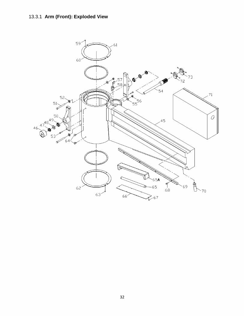
13.3.1 Arm (Front): Exploded View
33
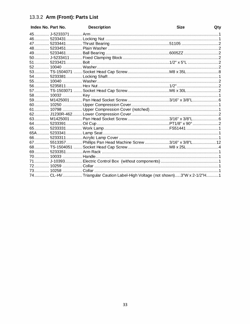
13.3.2 Arm (Front): Parts List
Index No. Part No. Description Size Qty 45 ............ J-5233371 .......... Arm ........................................................................................................ 1 46 ............ 5233431 ............. Locking Nut ............................................................................................ 1 47 ............ 5233441 ............. Thrust Bearing ................................................51105 .............................. 2 48 ............ 5233451 ............. Plain Washer .......................................................................................... 2 49 ............ 5233461 ............. Ball Bearing ....................................................6005ZZ ............................ 2 50 ............ J-5233411 .......... Fixed Clamping Block .............................................................................. 2 51 ............ 5233421 ............. Bolt ................................................................1/2" x 5”L ......................... 2 52 ............ 10040 ................ Washer................................................................................................... 2 53 ............ TS-1504071 ....... Socket Head Cap Screw ..................................M8 x 35L .......................... 8 54 ............ 5233381 ............. Locking Shaft .......................................................................................... 1 55 ............ 10040 ................ Washer................................................................................................... 2 56 ............ 5235811 ............. Hex Nut ..........................................................1/2" .................................. 2 57 ............ TS-1503071 ....... Socket Head Cap Screw ..................................M6 x 30L .......................... 2 58 ............ 10032 ................ Key ........................................................................................................ 1 59 ............ M1425001 .......... Pan Head Socket Screw ..................................3/16” x 3/8”L ..................... 6 60 ............ 10250 ................ Upper Compression Cover....................................................................... 1 61 ............ 10798 ................ Upper Compression Cover (notched)........................................................ 1 62 ............ J1230R-462........ Lower Compression Cover....................................................................... 2 63 ............ M1425001 .......... Pan Head Socket Screw ..................................3/16” x 3/8”L ..................... 6 64 ............ 5233391 ............. Oil Cup ...........................................................PT1/8” x 90° ..................... 2 65 ............ 5233331 ............. Work Lamp .....................................................FS51441 .......................... 1 65A.......... 5233341 ............. Lamp Seat .............................................................................................. 1 66 ............ 5233311 ............. Acrylic Lamp Cover ................................................................................. 1 67 ............ 5513357 ............. Phillips Pan Head Machine Screw ....................3/16” x 3/8”L ................... 12 68 ............ TS-1504051 ....... Socket Head Cap Screw ..................................M8 x 25L .......................... 4 69 ............ 5233351 ............. Arm Rack ............................................................................................... 1 70 ............ 10033 ................ Handle.................................................................................................... 1 71 ............ J-10393 .............. Electric Control Box (without components) ............................................... 1 72 ............ 10259 ................ Collar ..................................................................................................... 1 73 ............ 10258 ................ Collar ..................................................................................................... 1 74 ............ CL-HV ................ Triangular Caution Label-High Voltage (not shown).....3”W x 2-1/2”H.......... 1
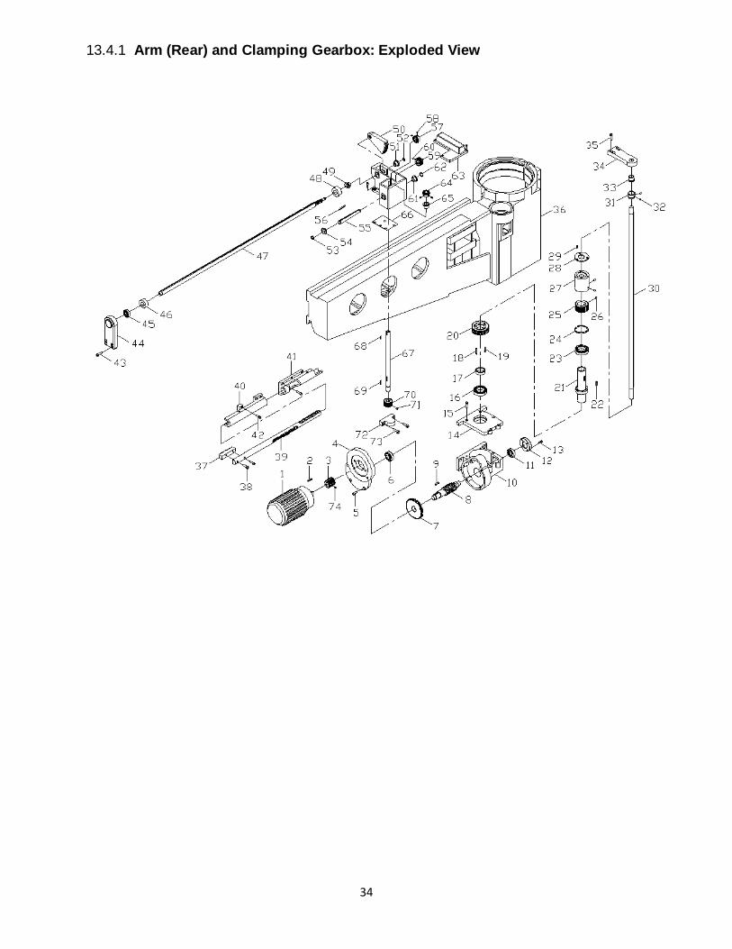
34
13.4.1 Arm (Rear) and Clamping Gearbox: Exploded View
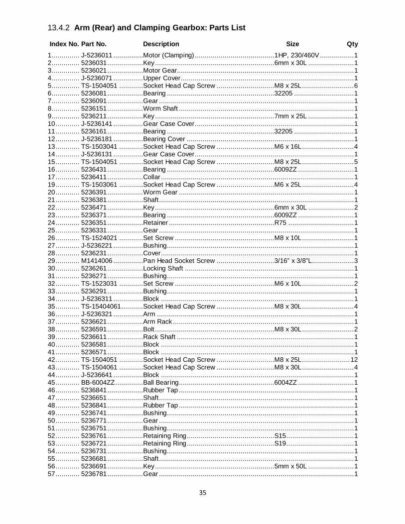
35
13.4.2 Arm (Rear) and Clamping Gearbox: Parts List
Index No. Part No. Description Size Qty 1 .............. J-5236011 ...............Motor (Clamping) ........................................1HP, 230/460V ................. 1 2 .............. 5236031 ..................Key ............................................................6mm x 30L ....................... 1 3 .............. 5236021 ..................Motor Gear ......................................................................................... 1 4 .............. J-5236071 ...............Upper Cover ....................................................................................... 1 5 .............. TS-1504051 ............Socket Head Cap Screw .............................M8 x 25L .......................... 6 6 .............. 5236081 ..................Bearing ......................................................32205 .............................. 1 7 .............. 5236091 ..................Gear .................................................................................................. 1 8 .............. 5236151 ..................Worm Shaft ........................................................................................ 1 9 .............. 5236211 ..................Key ............................................................7mm x 25L ....................... 1 10 ............ J-5236141 ...............Gear Case Cover................................................................................ 1 11 ............ 5236161 ..................Bearing ......................................................32205 .............................. 1 12 ............ J-5236181 ...............Bearing Cover .................................................................................... 1 13 ............ TS-1503041 ............Socket Head Cap Screw .............................M6 x 16L .......................... 4 14 ............ J-5236131 ...............Gear Case Cover................................................................................ 1 15 ............ TS-1504051 ............Socket Head Cap Screw .............................M8 x 25L .......................... 5 16 ............ 5236431 ..................Bearing ......................................................6009ZZ ............................ 1 17 ............ 5236411 ..................Collar ................................................................................................. 1 19 ............ TS-1503061 ............Socket Head Cap Screw .............................M6 x 25L .......................... 4 20 ............ 5236391 ..................Worm Gear ........................................................................................ 1 21 ............ 5236381 ..................Shaft .................................................................................................. 1 22 ............ 5236471 ..................Key ............................................................6mm x 30L ....................... 2 23 ............ 5236371 ..................Bearing ......................................................6009ZZ ............................ 1 24 ............ 5236351 ..................Retainer .....................................................R75 ................................. 1 25 ............ 5236331 ..................Gear .................................................................................................. 1 26 ............ TS-1524021 ............Set Screw ..................................................M8 x 10L .......................... 1 27 ............ J-5236221 ...............Bushing.............................................................................................. 1 28 ............ 5236231 ..................Cover ................................................................................................. 1 29 ............ M1414006 ...............Pan Head Socket Screw .............................3/16” x 3/8”L ..................... 3 30 ............ 5236261 ..................Locking Shaft ..................................................................................... 1 31 ............ 5236271 ..................Bushing.............................................................................................. 1 32 ............ TS-1523031 ............Set Screw ..................................................M6 x 10L .......................... 2 33 ............ 5236291 ..................Bushing.............................................................................................. 1 34 ............ J-5236311 ...............Block ................................................................................................. 1 35 ............ TS-15404061...........Socket Head Cap Screw .............................M8 x 30L .......................... 4 36 ............ J-5236321 ...............Arm ................................................................................................... 1 37 ............ 5236621 ..................Arm Rack ........................................................................................... 1 38 ............ 5236591 ..................Bolt ............................................................M8 x 30L .......................... 2 39 ............ 5236611 ..................Rack Shaft ......................................................................................... 1 40 ............ 5236581 ..................Block ................................................................................................. 1 41 ............ 5236571 ..................Block ................................................................................................. 1 42 ............ TS-1504051 ............Socket Head Cap Screw .............................M8 x 25L ........................ 12 43 ............ TS-1504061 ............Socket Head Cap Screw .............................M8 x 30L .......................... 4 44 ............ J-5236641 ...............Block ................................................................................................. 1 45 ............ BB-6004ZZ ..............Ball Bearing................................................6004ZZ ............................ 1 46 ............ 5236841 ..................Rubber Tap ........................................................................................ 1 47 ............ 5236651 ..................Shaft .................................................................................................. 1 48 ............ 5236841 ..................Rubber Tap ........................................................................................ 1 49 ............ 5236741 ..................Bushing.............................................................................................. 1 50 ............ 5236771 ..................Gear .................................................................................................. 1 51 ............ 5236751 ..................Bushing.............................................................................................. 1 52 ............ 5236761 ..................Retaining Ring ............................................S15.................................. 1 53 ............ 5236721 ..................Retaining Ring ............................................S19.................................. 1 54 ............ 5236731 ..................Bushing.............................................................................................. 1 55 ............ 5236681 ..................Shaft .................................................................................................. 1 56 ............ 5236691 ..................Key ............................................................5mm x 50L ....................... 1 57 ............ 5236781 ..................Gear .................................................................................................. 1
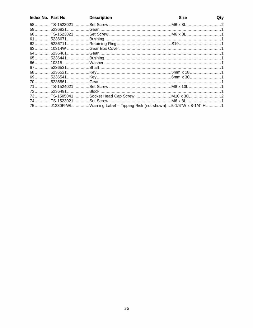
36
Index No. Part No. Description Size Qty 58 ............ TS-1523021 ............Set Screw ..................................................M6 x 8L ............................ 2 59 ............ 5236821 ..................Gear .................................................................................................. 1 60 ............ TS-1523021 ............Set Screw ..................................................M6 x 8L ............................ 1 61 ............ 5236671 ..................Bushing.............................................................................................. 1 62 ............ 5236711 ..................Retaining Ring ............................................S19.................................. 1 63 ............ 10314W ..................Gear Box Cover .................................................................................. 1 64 ............ 5236461 ..................Gear .................................................................................................. 1 65 ............ 5236441 ..................Bushing.............................................................................................. 1 66 ............ 10315 .....................Washer .............................................................................................. 1 67 ............ 5236531 ..................Shaft .................................................................................................. 1 68 ............ 5236521 ..................Key ............................................................5mm x 18L ....................... 1 69 ............ 5236541 ..................Key ............................................................6mm x 30L ....................... 1 70 ............ 5236561 ..................Gear .................................................................................................. 1 71 ............ TS-1524021 ............Set Screw ..................................................M8 x 10L .......................... 1 72 ............ 5236491 ..................Block ................................................................................................. 1 73 ............ TS-1505041 ............Socket Head Cap Screw .............................M10 x 30L ........................ 2 74 ............ TS-1523021 ............Set Screw ..................................................M6 x 8L ............................ 1 75 ............ J1230R-WL .............Warning Label – Tipping Risk (not shown) ....5-1/4”W x 8-1/4” H ............ 1
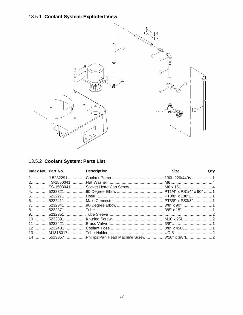
37
13.5.1 Coolant System: Exploded View
13.5.2 Coolant System: Parts List
Index No. Part No. Description Size Qty 1 .............. J-5232291 ...............Coolant Pump ............................................130L 220/440V ................. 1 2 .............. TS-1550041 ............Flat Washer................................................M6 ................................... 4 3 .............. TS-1503041 ............Socket Head Cap Screw .............................M6 x 16L .......................... 4 4 .............. 5232321 ..................90-Degree Elbow ........................................PT1/4” x PS1/4” x 90° ....... 1 5 .............. 5232271 ..................Hose ..........................................................PT3/8” x 130”L.................. 1 6 .............. 5232411 ..................Male Connector ..........................................PT3/8” x PS3/8” ................ 1 7 .............. 5232341 ..................90-Degree Elbow ........................................3/8” x 90° ......................... 1 8 .............. 5232371 ..................Tube ..........................................................3/8” x 15”L........................ 1 9 .............. 5232351 ..................Tube Sleeve ....................................................................................... 2 10 ............ 5232391 ..................Knurled Screw ............................................M10 x 25L ........................ 2 11 ............ 5232421 ..................Brass Valve ................................................3/8” .................................. 1 12 ............ 5232431 ..................Coolant Hose .............................................3/8” x 450L ....................... 1 13 ............ M1315017 ...............Tube Holder ...............................................UC-5 ................................ 2 14 ............ 5513357 ..................Phillips Pan Head Machine Screw................3/16” x 3/8”L ..................... 2
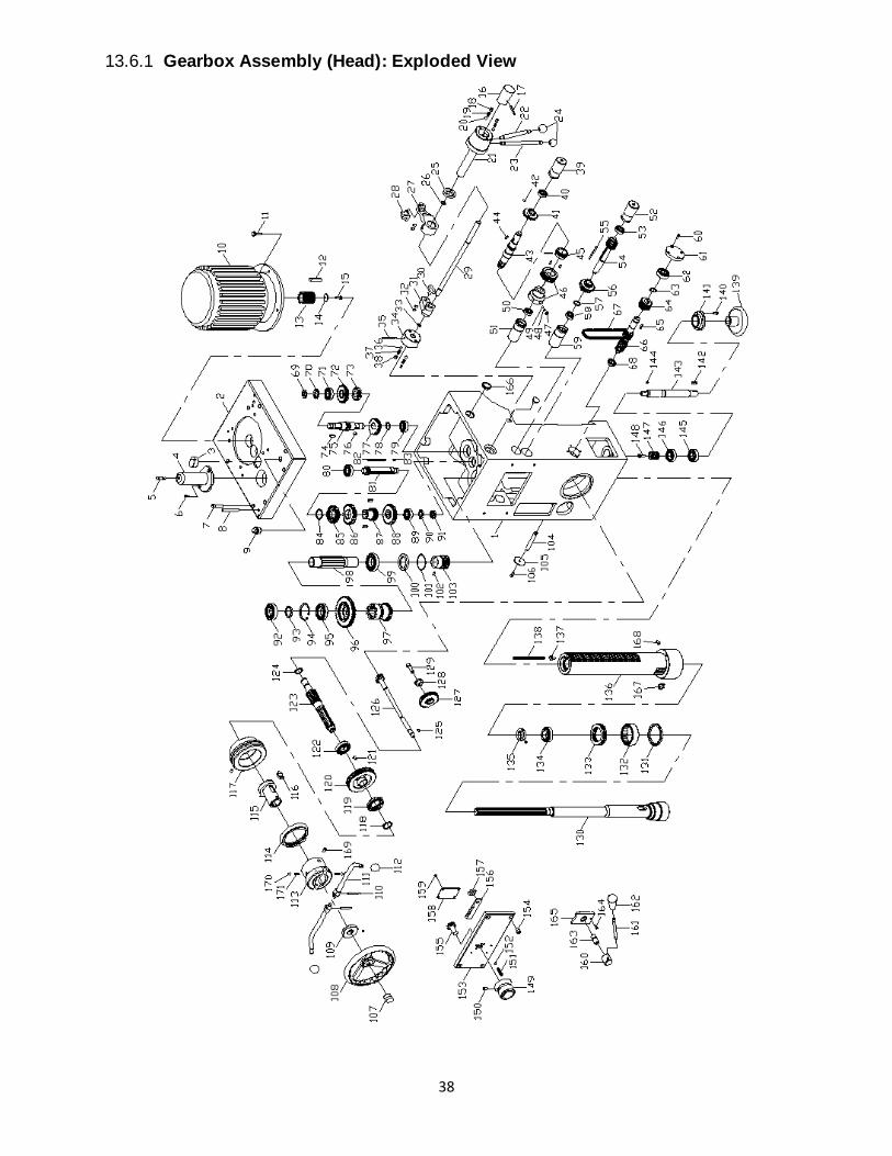
38
13.6.1 Gearbox Assembly (Head): Exploded View
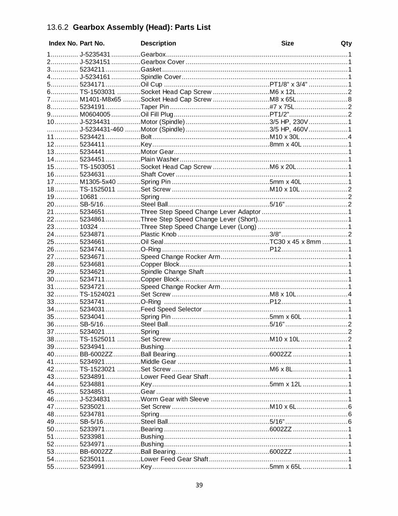
39
13.6.2 Gearbox Assembly (Head): Parts List
Index No. Part No. Description Size Qty 1 .............. J-5235431 ...............Gearbox ............................................................................................. 1 2 .............. J-5234151 ...............Gearbox Cover ................................................................................... 1 3 .............. 5234211 ..................Gasket ............................................................................................... 1 4 .............. J-5234161 ...............Spindle Cover..................................................................................... 1 5 .............. 5234171 ..................Oil Cup ......................................................PT1/8” x 3/4” .................... 1 6 .............. TS-1503031 ............Socket Head Cap Screw .............................M6 x 12L .......................... 2 7 .............. M1401-M8x65 .........Socket Head Cap Screw .............................M8 x 65L .......................... 8 8 .............. 5234191 ..................Taper Pin ...................................................#7 x 75L ........................... 2 9 .............. M0604005 ...............Oil Fill Plug .................................................PT1/2”.............................. 2 10 ............ J-5234431 ...............Motor (Spindle) ...........................................3/5 HP, 230V .................... 1 ................ J-5234431-460 ........Motor (Spindle) ...........................................3/5 HP, 460V .................... 1 11 ............ 5234421 ..................Bolt ............................................................M10 x 30L ........................ 4 12 ............ 5234411 ..................Key ............................................................8mm x 40L ....................... 1 13 ............ 5234441 ..................Motor Gear ......................................................................................... 1 14 ............ 5234451 ..................Plain Washer ...................................................................................... 1 15 ............ TS-1503051 ............Socket Head Cap Screw .............................M6 x 20L .......................... 1 16 ............ 5234631 ..................Shaft Cover ........................................................................................ 1 17 ............ M1305-5x40 ............Spring Pin ..................................................5mm x 40L ....................... 1 18 ............ TS-1525011 ............Set Screw ..................................................M10 x 10L ........................ 2 19 ............ 10681 .....................Spring ................................................................................................ 2 20 ............ SB-5/16 ...................Steel Ball....................................................5/16” ................................ 2 21 ............ 5234651 ..................Three Step Speed Change Lever Adaptor ............................................ 1 22 ............ 5234861 ..................Three Step Speed Change Lever (Short).............................................. 1 23 ............ 10324 .....................Three Step Speed Change Lever (Long) .............................................. 1 24 ............ 5234871 ..................Plastic Knob ...............................................3/8” .................................. 2 25 ............ 5234661 ..................Oil Seal ......................................................TC30 x 45 x 8mm ............. 1 26 ............ 5234741 ..................O-Ring .......................................................P12.................................. 1 27 ............ 5234671 ..................Speed Change Rocker Arm ................................................................. 1 28 ............ 5234681 ..................Copper Block...................................................................................... 1 29 ............ 5234621 ..................Spindle Change Shaft ......................................................................... 1 30 ............ 5234711 ..................Copper Block...................................................................................... 1 31 ............ 5234721 ..................Speed Change Rocker Arm ................................................................. 1 32 ............ TS-1524021 ............Set Screw ..................................................M8 x 10L .......................... 4 33 ............ 5234741 ..................O-Ring ......................................................P12.................................. 1 34 ............ 5234031 ..................Feed Speed Selector .......................................................................... 1 35 ............ 5234041 ..................Spring Pin ..................................................5mm x 60L ....................... 1 36 ............ SB-5/16 ...................Steel Ball....................................................5/16” ................................ 2 37 ............ 5234021 ..................Spring ................................................................................................ 2 38 ............ TS-1525011 ............Set Screw ..................................................M10 x 10L ........................ 2 39 ............ 5234941 ..................Bushing.............................................................................................. 1 40 ............ BB-6002ZZ ..............Ball Bearing................................................6002ZZ ............................ 1 41 ............ 5234921 ..................Middle Gear ....................................................................................... 1 42 ............ TS-1523021 ............Set Screw ..................................................M6 x 8L ............................ 1 43 ............ 5234891 ..................Lower Feed Gear Shaft ....................................................................... 1 44 ............ 5234881 ..................Key ............................................................5mm x 12L ....................... 1 45 ............ 5234851 ..................Gear .................................................................................................. 1 46 ............ J-5234831 ...............Worm Gear with Sleeve ...................................................................... 1 47 ............ 5235021 ..................Set Screw ..................................................M10 x 6L .......................... 6 48 ............ 5234781 ..................Spring ................................................................................................ 6 49 ............ SB-5/16 ...................Steel Ball....................................................5/16” ................................ 6 50 ............ 5233971 ..................Bearing ......................................................6002ZZ ............................ 1 51 ............ 5233981 ..................Bushing.............................................................................................. 1 52 ............ 5234971 ..................Bushing.............................................................................................. 1 53 ............ BB-6002ZZ ..............Ball Bearing................................................6002ZZ ............................ 1 54 ............ 5235011 ..................Lower Feed Gear Shaft ....................................................................... 1 55 ............ 5234991 ..................Key ............................................................5mm x 65L ....................... 1
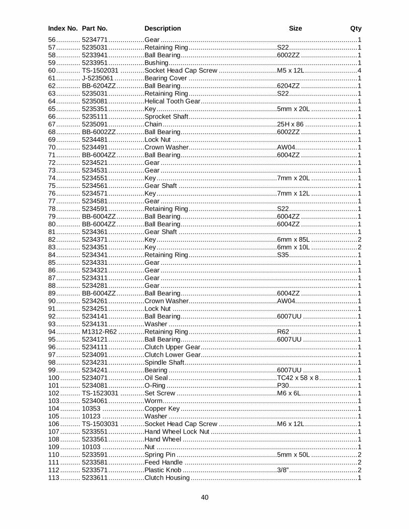
40
Index No. Part No. Description Size Qty 56 ............ 5234771 ..................Gear .................................................................................................. 1 57 ............ 5235031 ..................Retaining Ring ............................................S22.................................. 1 58 ............ 5233941 ..................Ball Bearing................................................6002ZZ ............................ 1 59 ............ 5233951 ..................Bushing.............................................................................................. 1 60 ............ TS-1502031 ............Socket Head Cap Screw .............................M5 x 12L .......................... 4 61 ............ J-5235061 ...............Bearing Cover .................................................................................... 1 62 ............ BB-6204ZZ ..............Ball Bearing................................................6204ZZ ............................ 1 63 ............ 5235031 ..................Retaining Ring ............................................S22.................................. 1 64 ............ 5235081 ..................Helical Tooth Gear .............................................................................. 1 65 ............ 5235351 ..................Key ............................................................5mm x 20L ....................... 1 66 ............ 5235111 ..................Sprocket Shaft .................................................................................... 1 67 ............ 5235091 ..................Chain .........................................................25H x 86 .......................... 1 68 ............ BB-6002ZZ ..............Ball Bearing................................................6002ZZ ............................ 1 69 ............ 5234481 ..................Lock Nut ............................................................................................ 1 70 ............ 5234491 ..................Crown Washer............................................AW04............................... 1 71 ............ BB-6004ZZ ..............Ball Bearing................................................6004ZZ ............................ 1 72 ............ 5234521 ..................Gear .................................................................................................. 1 73 ............ 5234531 ..................Gear .................................................................................................. 1 74 ............ 5234551 ..................Key ............................................................7mm x 20L ....................... 1 75 ............ 5234561 ..................Gear Shaft ......................................................................................... 1 76 ............ 5234571 ..................Key ............................................................7mm x 12L ....................... 1 77 ............ 5234581 ..................Gear .................................................................................................. 1 78 ............ 5234591 ..................Retaining Ring ............................................S22.................................. 1 79 ............ BB-6004ZZ ..............Ball Bearing................................................6004ZZ ............................ 1 80 ............ BB-6004ZZ ..............Ball Bearing................................................6004ZZ ............................ 1 81 ............ 5234361 ..................Gear Shaft ......................................................................................... 1 82 ............ 5234371 ..................Key ............................................................6mm x 85L ....................... 2 83 ............ 5234351 ..................Key ............................................................6mm x 10L ....................... 2 84 ............ 5234341 ..................Retaining Ring ............................................S35.................................. 1 85 ............ 5234331 ..................Gear .................................................................................................. 1 86 ............ 5234321 ..................Gear .................................................................................................. 1 87 ............ 5234311 ..................Gear .................................................................................................. 1 88 ............ 5234281 ..................Gear .................................................................................................. 1 89 ............ BB-6004ZZ ..............Ball Bearing................................................6004ZZ ............................ 1 90 ............ 5234261 ..................Crown Washer............................................AW04............................... 1 91 ............ 5234251 ..................Lock Nut ............................................................................................ 1 92 ............ 5234141 ..................Ball Bearing................................................6007UU ........................... 1 93 ............ 5234131 ..................Washer .............................................................................................. 1 94 ............ M1312-R62 .............Retaining Ring ............................................R62 ................................. 1 95 ............ 5234121 ..................Ball Bearing................................................6007UU ........................... 1 96 ............ 5234111 ..................Clutch Upper Gear .............................................................................. 1 97 ............ 5234091 ..................Clutch Lower Gear .............................................................................. 1 98 ............ 5234231 ..................Spindle Shaft ...................................................................................... 1 99 ............ 5234241 ..................Bearing ......................................................6007UU ........................... 1 100 .......... 5234071 ..................Oil Seal ......................................................TC42 x 58 x 8 ................... 1 101 .......... 5234081 ..................O-Ring .......................................................P30.................................. 1 102 .......... TS-1523031 ............Set Screw ..................................................M6 x 6L ............................ 1 103 .......... 5234061 ..................Worm ................................................................................................. 1 104 .......... 10353 .....................Copper Key ........................................................................................ 1 105 .......... 10123 .....................Washer .............................................................................................. 1 106 .......... TS-1503031 ............Socket Head Cap Screw .............................M6 x 12L .......................... 1 107 .......... 5233551 ..................Hand Wheel Lock Nut ......................................................................... 1 108 .......... 5233561 ..................Hand Wheel ....................................................................................... 1 109 .......... 10103 .....................Nut .................................................................................................... 1 110 .......... 5233591 ..................Spring Pin ..................................................5mm x 50L ....................... 2 111 .......... 5233581 ..................Feed Handle ...................................................................................... 2 112 .......... 5233571 ..................Plastic Knob ...............................................3/8” .................................. 2 113 .......... 5233611 ..................Clutch Housing ................................................................................... 1
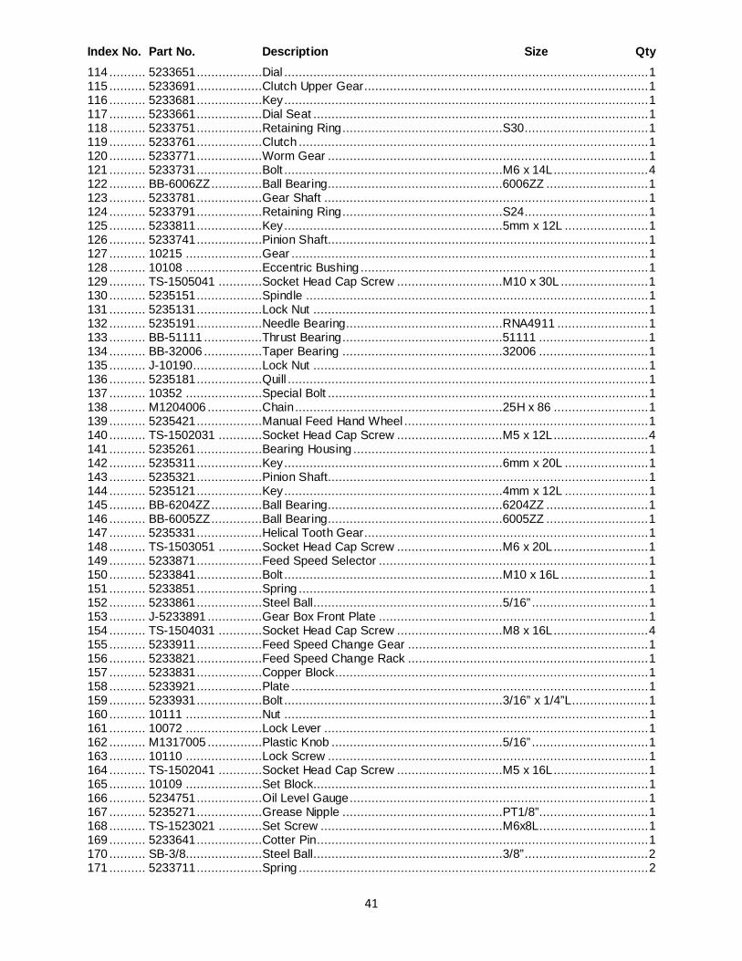
41
Index No. Part No. Description Size Qty 114 .......... 5233651 ..................Dial .................................................................................................... 1 115 .......... 5233691 ..................Clutch Upper Gear .............................................................................. 1 116 .......... 5233681 ..................Key .................................................................................................... 1 117 .......... 5233661 ..................Dial Seat ............................................................................................ 1 118 .......... 5233751 ..................Retaining Ring ............................................S30.................................. 1 119 .......... 5233761 ..................Clutch ................................................................................................ 1 120 .......... 5233771 ..................Worm Gear ........................................................................................ 1 121 .......... 5233731 ..................Bolt ............................................................M6 x 14L .......................... 4 122 .......... BB-6006ZZ ..............Ball Bearing................................................6006ZZ ............................ 1 123 .......... 5233781 ..................Gear Shaft ......................................................................................... 1 124 .......... 5233791 ..................Retaining Ring ............................................S24.................................. 1 125 .......... 5233811 ..................Key ............................................................5mm x 12L ....................... 1 126 .......... 5233741 ..................Pinion Shaft........................................................................................ 1 127 .......... 10215 .....................Gear .................................................................................................. 1 128 .......... 10108 .....................Eccentric Bushing ............................................................................... 1 129 .......... TS-1505041 ............Socket Head Cap Screw .............................M10 x 30L ........................ 1 130 .......... 5235151 ..................Spindle .............................................................................................. 1 131 .......... 5235131 ..................Lock Nut ............................................................................................ 1 132 .......... 5235191 ..................Needle Bearing...........................................RNA4911 ......................... 1 133 .......... BB-51111 ................Thrust Bearing ............................................51111 .............................. 1 134 .......... BB-32006 ................Taper Bearing ............................................32006 .............................. 1 135 .......... J-10190 ...................Lock Nut ............................................................................................ 1 136 .......... 5235181 ..................Quill ................................................................................................... 1 137 .......... 10352 .....................Special Bolt ........................................................................................ 1 138 .......... M1204006 ...............Chain .........................................................25H x 86 .......................... 1 139 .......... 5235421 ..................Manual Feed Hand Wheel ................................................................... 1 140 .......... TS-1502031 ............Socket Head Cap Screw .............................M5 x 12L .......................... 4 141 .......... 5235261 ..................Bearing Housing ................................................................................. 1 142 .......... 5235311 ..................Key ............................................................6mm x 20L ....................... 1 143 .......... 5235321 ..................Pinion Shaft........................................................................................ 1 144 .......... 5235121 ..................Key ............................................................4mm x 12L ....................... 1 145 .......... BB-6204ZZ ..............Ball Bearing................................................6204ZZ ............................ 1 146 .......... BB-6005ZZ ..............Ball Bearing................................................6005ZZ ............................ 1 147 .......... 5235331 ..................Helical Tooth Gear .............................................................................. 1 148 .......... TS-1503051 ............Socket Head Cap Screw .............................M6 x 20L .......................... 1 149 .......... 5233871 ..................Feed Speed Selector .......................................................................... 1 150 .......... 5233841 ..................Bolt ............................................................M10 x 16L ........................ 1 151 .......... 5233851 ..................Spring ................................................................................................ 1 152 .......... 5233861 ..................Steel Ball....................................................5/16” ................................ 1 153 .......... J-5233891 ...............Gear Box Front Plate .......................................................................... 1 154 .......... TS-1504031 ............Socket Head Cap Screw .............................M8 x 16L .......................... 4 155 .......... 5233911 ..................Feed Speed Change Gear .................................................................. 1 156 .......... 5233821 ..................Feed Speed Change Rack .................................................................. 1 157 .......... 5233831 ..................Copper Block...................................................................................... 1 158 .......... 5233921 ..................Plate .................................................................................................. 1 159 .......... 5233931 ..................Bolt ............................................................3/16” x 1/4”L ..................... 1 160 .......... 10111 .....................Nut .................................................................................................... 1 161 .......... 10072 .....................Lock Lever ......................................................................................... 1 162 .......... M1317005 ...............Plastic Knob ...............................................5/16” ................................ 1 163 .......... 10110 .....................Lock Screw ........................................................................................ 1 164 .......... TS-1502041 ............Socket Head Cap Screw .............................M5 x 16L .......................... 1 165 .......... 10109 .....................Set Block............................................................................................ 1 166 .......... 5234751 ..................Oil Level Gauge .................................................................................. 1 167 .......... 5235271 ..................Grease Nipple ............................................PT1/8”.............................. 1 168 .......... TS-1523021 ............Set Screw ..................................................M6x8L.............................. 1 169 .......... 5233641 ..................Cotter Pin ........................................................................................... 1 170 .......... SB-3/8.....................Steel Ball....................................................3/8” .................................. 2 171 .......... 5233711 ..................Spring ................................................................................................ 2
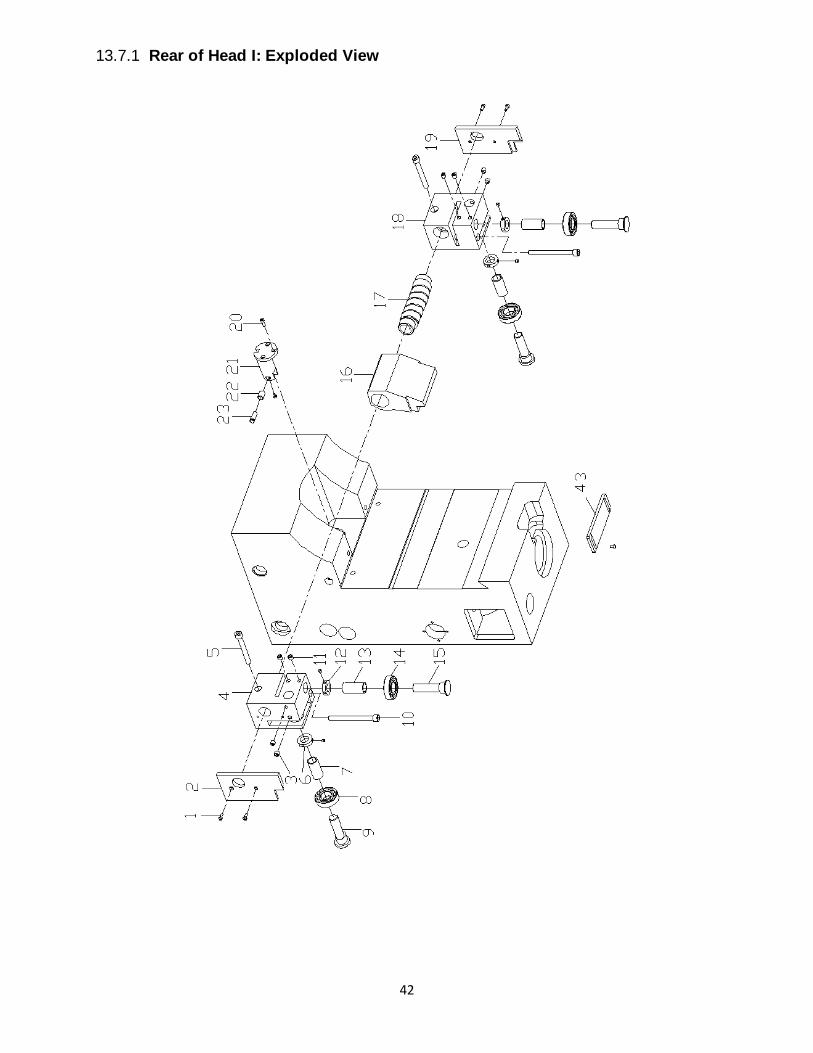
42
13.7.1 Rear of Head I: Exploded View
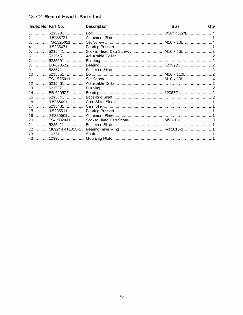
43
13.7.2 Rear of Head I: Parts List
Index No. Part No. Description Size Qty 1 .............. 5235731 ..................Bolt ............................................................3/16” x 1/2"L ..................... 4 2 .............. J-5235721 ...............Aluminum Plate .................................................................................. 1 3 .............. TS-1525011 ............Set Screw ..................................................M10 x 10L ........................ 4 4 .............. J-5235471 ...............Bearing Bracket .................................................................................. 1 5 .............. 5235441 ..................Socket Head Cap Screw .............................M10 x 85L ........................ 2 6 .............. 5235451 ..................Adjustable Collar ................................................................................ 2 7 .............. 5235691 ..................Bushing.............................................................................................. 2 8 .............. BB-6205ZZ ..............Bearing ......................................................6205ZZ ............................ 2 9 .............. 5235711 ..................Eccentric Shaft ................................................................................... 2 10 ............ 5235651 ..................Bolt ............................................................M10 x 110L ...................... 2 11 ............ TS-1525011 ............Set Screw ..................................................M10 x 10L ........................ 4 12 ............ 5235461 ..................Adjustable Collar ................................................................................ 2 13 ............ 5235671 ..................Bushing.............................................................................................. 2 14 ............ BB-6205ZZ ..............Bearing ......................................................6205ZZ ............................ 2 15 ............ 5235641 ..................Eccentric Shaft ................................................................................... 2 16 ............ J-5235491 ...............Cam Shaft Sleeve ............................................................................... 1 17 ............ 5235481 ..................Cam Shaft .......................................................................................... 1 18 ............ J-5235511 ...............Bearing Bracket .................................................................................. 1 19 ............ J-5235561 ...............Aluminum Plate .................................................................................. 1 20 ............ TS-1502041 ............Socket Head Cap Screw .............................M5 x 16L .......................... 3 21 ............ 5235421 ..................Eccentric Shaft ................................................................................... 1 22 ............ M0924-IRT1015-1 ....Bearing Inner Ring ......................................IRT1015-1 ........................ 1 23 ............ 10221 .....................Shaft .................................................................................................. 1 43 ............ 10356 .....................Mounting Plate ................................................................................... 1
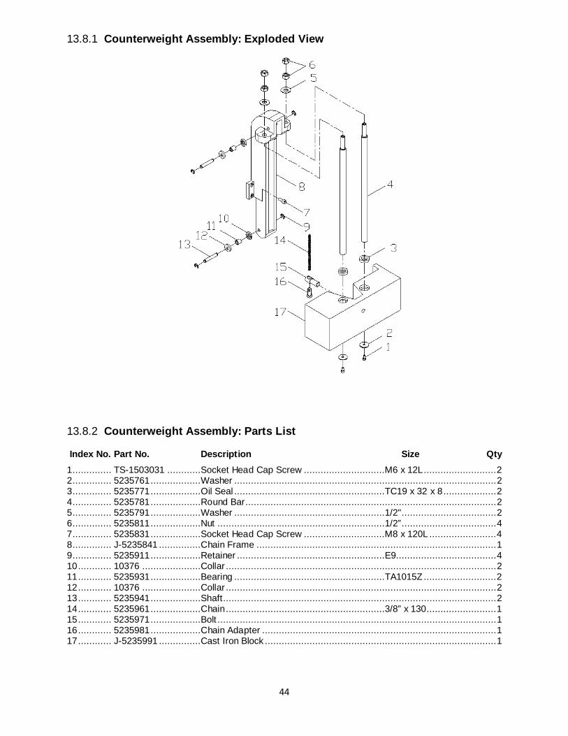
44
13.8.1 Counterweight Assembly: Exploded View
13.8.2 Counterweight Assembly: Parts List
Index No. Part No. Description Size Qty 1 .............. TS-1503031 ............Socket Head Cap Screw .............................M6 x 12L .......................... 2 2 .............. 5235761 ..................Washer .............................................................................................. 2 3 .............. 5235771 ..................Oil Seal ......................................................TC19 x 32 x 8 ................... 2 4 .............. 5235781 ..................Round Bar.......................................................................................... 2 5 .............. 5235791 ..................Washer ......................................................1/2" .................................. 2 6 .............. 5235811 ..................Nut ............................................................1/2” .................................. 4 7 .............. 5235831 ..................Socket Head Cap Screw .............................M8 x 120L ........................ 4 8 .............. J-5235841 ...............Chain Frame ...................................................................................... 1 9 .............. 5235911 ..................Retainer .....................................................E9.................................... 4 10 ............ 10376 .....................Collar ................................................................................................. 2 11 ............ 5235931 ..................Bearing ......................................................TA1015Z .......................... 2 12 ............ 10376 .....................Collar ................................................................................................. 2 13 ............ 5235941 ..................Shaft .................................................................................................. 2 14 ............ 5235961 ..................Chain .........................................................3/8” x 130 ......................... 1 15 ............ 5235971 ..................Bolt .................................................................................................... 1 16 ............ 5235981 ..................Chain Adapter .................................................................................... 1 17 ............ J-5235991 ...............Cast Iron Block ................................................................................... 1
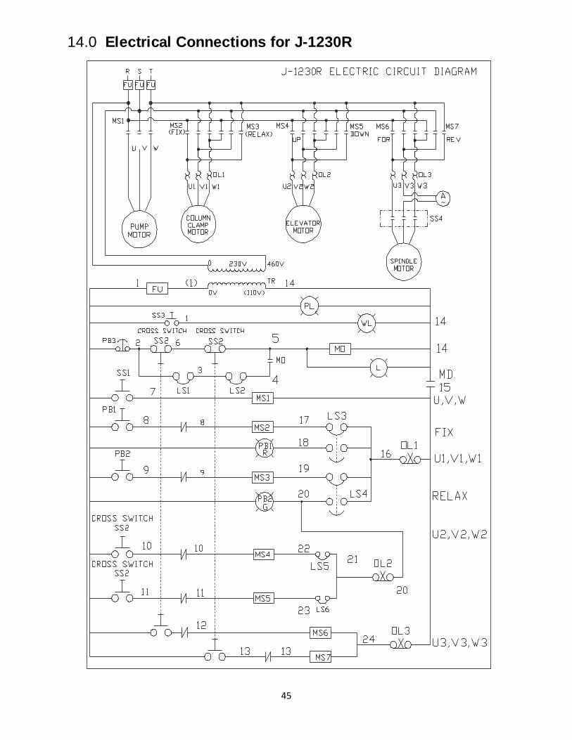
45
14.0 Electrical Connections for J-1230R
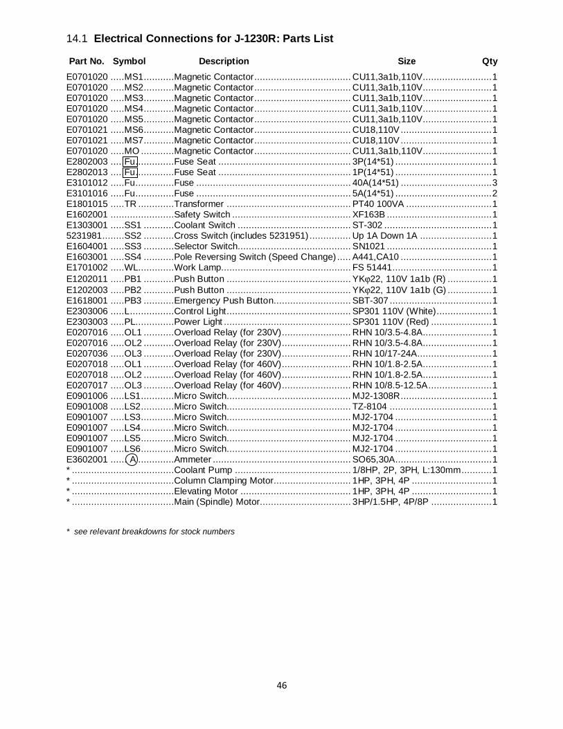
46
14.1 Electrical Connections for J-1230R: Parts List
Part No. Symbol Description Size Qty E0701020 .....MS1 ...........Magnetic Contactor ................................... CU11,3a1b,110V......................... 1 E0701020 .....MS2 ...........Magnetic Contactor ................................... CU11,3a1b,110V......................... 1 E0701020 .....MS3 ...........Magnetic Contactor ................................... CU11,3a1b,110V......................... 1 E0701020 .....MS4 ...........Magnetic Contactor ................................... CU11,3a1b,110V......................... 1 E0701020 .....MS5 ...........Magnetic Contactor ................................... CU11,3a1b,110V......................... 1 E0701021 .....MS6 ...........Magnetic Contactor ................................... CU18,110V ................................. 1 E0701021 .....MS7 ...........Magnetic Contactor ................................... CU18,110V ................................. 1 E0701020 .....MO ............Magnetic Contactor ................................... CU11,3a1b,110V......................... 1 E2802003 .....Fu ..............Fuse Seat ................................................ 3P(14*51) ................................... 1 E2802013 .....Fu ..............Fuse Seat ................................................ 1P(14*51) ................................... 1 E3101012 .....Fu ..............Fuse ........................................................ 40A(14*51) ................................. 3 E3101016 .....Fu ..............Fuse ........................................................ 5A(14*51) ................................... 2 E1801015 .....TR .............Transformer ............................................. PT40 100VA ............................... 1 E1602001 .......................Safety Switch ........................................... XF163B ...................................... 1 E1303001 .....SS1 ...........Coolant Switch ......................................... ST-302 ....................................... 1 5231981........SS2 ...........Cross Switch (includes 5231951) ............... Up 1A Down 1A .......................... 1 E1604001 .....SS3 ...........Selector Switch......................................... SN1021 ...................................... 1 E1603001 .....SS4 ...........Pole Reversing Switch (Speed Change) ..... A441,CA10 ................................. 1 E1701002 .....WL.............Work Lamp............................................... FS 51441.................................... 1 E1202011 .....PB1 ...........Push Button ............................................. YKϕ22, 110V 1a1b (R) ................ 1 E1202003 .....PB2 ...........Push Button ............................................. YKϕ22, 110V 1a1b (G) ................ 1 E1618001 .....PB3 ...........Emergency Push Button............................ SBT-307 ..................................... 1 E2303006 .....L ................Control Light ............................................. SP301 110V (White) .................... 1 E2303003 .....PL..............Power Light .............................................. SP301 110V (Red) ...................... 1 E0207016 .....OL1 ...........Overload Relay (for 230V) ......................... RHN 10/3.5-4.8A ......................... 1 E0207016 .....OL2 ...........Overload Relay (for 230V) ......................... RHN 10/3.5-4.8A ......................... 1 E0207036 .....OL3 ...........Overload Relay (for 230V) ......................... RHN 10/17-24A........................... 1 E0207018 .....OL1 ...........Overload Relay (for 460V) ......................... RHN 10/1.8-2.5A ......................... 1 E0207018 .....OL2 ...........Overload Relay (for 460V) ......................... RHN 10/1.8-2.5A ......................... 1 E0207017 .....OL3 ...........Overload Relay (for 460V) ......................... RHN 10/8.5-12.5A ....................... 1 E0901006 .....LS1............Micro Switch ............................................. MJ2-1308R ................................. 1 E0901008 .....LS2............Micro Switch ............................................. TZ-8104 ..................................... 1 E0901007 .....LS3............Micro Switch ............................................. MJ2-1704 ................................... 1 E0901007 .....LS4............Micro Switch ............................................. MJ2-1704 ................................... 1 E0901007 .....LS5............Micro Switch ............................................. MJ2-1704 ................................... 1 E0901007 .....LS6............Micro Switch ............................................. MJ2-1704 ................................... 1 E3602001 ...... A .............Ammeter .................................................. SO65,30A ................................... 1 * .....................................Coolant Pump .......................................... 1/8HP, 2P, 3PH, L:130mm ........... 1 * .....................................Column Clamping Motor............................ 1HP, 3PH, 4P ............................. 1 * .....................................Elevating Motor ........................................ 1HP, 3PH, 4P ............................. 1 * .....................................Main (Spindle) Motor................................. 3HP/1.5HP, 4P/8P ...................... 1 * see relevant breakdowns for stock numbers

47

48
WALTER MEIER (Manufacturing) Inc. 427 New Sanford Road
LaVergne, Tennessee 37086 Phone: 800-274-6848 www.jettools.com
www.waltermeier.com