opdisys fiber to the home - solution - penggkabel.at · fáñáåÖ ëÉíë several fixing sets...
TRANSCRIPT

OPDISYS® Fiber to the Home - Solution

Technical data:
• maximum fiber density: 960 fibers at SC,
1920 fibers at LC and E2000
• comfortable patching with two-sided over-
length patchcord storage
• optional extensions (for cable guidance and
gasblocker integration)
• available as open and closed rack version
• removable and rotatable splice/patch fiber
module
• fiber module frontplate with different cut-
outs and adapter mounting through snap-in
angled holder available: SC, LC, E2000
(others on request)
• optional integration of gas-blockers on
incoming tubes possible (on request)
• colour: RAL 7035, light grey
• material: Powder coated steel
• flammability: UL 94V-0
The OPDISYS®-rack was specially designed for Fiber-To-The-Home (FTTH) applications. It is a modular system consisting of a basic rack, cable
management, mandrel extension racks and gasblocker extension racks and fiber modules. Thanks to its design this system is very flexible. The
extension racks can be ordered and combined individually according to the customer´s needs. Each fiber module has a front plate with two
types of uniform cut-out patterns into which snap-in angled holders fitting into the required adapter type can be inserted. This snap-in angled
holder also ensures a 45 degree angle of the adapter is maintained. Each fiber module can be used as a left-side as well as a right-side fiber
module.
By default, there are protection tubes from the cable clamp to each individual module is installed by kink-resistant PBT-tubes. They ensure that
the minimum curve radius of the cable loose tubes from the cable entry to the fiber modules will not be exceeded.
The cable clamps are pre-installed either on the top or on the bottom of the rack and are used to secure the strain relief of the incoming cables.
They serve further as a fixing point for the cable tubes. Optionally, the strain relief element of the incoming cable to be attached.
OPDISYS®-rack
The OPDISYS®-rack is the core component of every OPDISYS®-system. Both, an open version as well as a closed version, are available. An
open version rack is turned into a closed version rack by installing side panels and doors. The rack accommodates the fiber module carrier, the
cable entry plates, all types of extension modules and, if a closed version is required, the side panels as well as the front doors.
Various fixing sets (see information in the accessories section of this document) are available which allow you to mount the rack to either wall or
ceiling or floor. It is possible to mount several racks next to each other back-to-back (requires only floor mounting) or next to each other (requires
mounting both to floor and ceiling or wall for stability reasons). A stand-alone Single Row Rack should always be fixed to both floor and ceiling
or wall.
Optical distribution system

3OPDISYS® Fiber to the Home - Solution • 02/2016 • © by Pengg Kabel GmbH • Technische Änderungen vorbehalten
OPDISYS®-rack - possible extensions (on request)
Gasblocker - extension rack
When using blow-in systems, gasblockers are essential in order to protect the installation against gas
and/or water entry. The gasblocker extension rack can accommodate the gasblockers. It has a built-in
back panel, so no extra back panel is needed in order to turn it into a closed version.
Rack doors, side and back panels
If a closed rack version is required, doors and panels can be attached to rack. Each door has an opening
angle of 180°. The doors are equipped with an integrated lever and lock and have an A4 document holder
on their inner side. Each side panel is useable for right as well as for left side mounting.
Rack features:
• top or bottom cable entry possible
• top cover provides openings for cables (optionally with brushes)
• easy expansion with side-by-side or back-to-back mounting of racks
• solutions for cross-connect and interconnect configurations
• backside vertical cable guidance for incoming cables
• bending radius protection of 30mm for fibers and patchcords
• intelligent patchcord management
• vertical patchcord cable guidance on left and right side
• mandrels on left and right side of the rack provide sufficient space for patchcord overlength storage
• integrated patchcord management to adjacent racks avoids the usage of external ducts
Dimensions & capacity - standard version (incl. mandrels)
OPDISYS®-rack 1000/40HU
Rack height 2200 mm
Rack width 1000 mm
Rack weight (open / closed) 118 kg / 170 kg
Max. amount of modules 80 Full-Size or 160 Half-Size
Max. amount of terminations 960 SC
1920 LC / E2000
OPDISYS®-rack 1000/40HU incl. mandrels, protective tubes
Art. No. 2735153
Gasblocker - extension rack on request
Panels / door set Art. No. 2735154

Fixing sets
Several fixing sets are available to mount the rack to the wall, on the floor or to mount multiple racks side
by side or back to back to each other. Each individual fixing set contains all necessary screws, mounting
brackets, washers and anchor pins.
Tool kit
• adapter holder pincer
The adapter holder pincer is designed to easily remove the snap-in angled holder from the frontplate
cutout of the OPDISYS® fiber module. Thanks to its small and compact design it ensures the smooth
removal of a snap-in angled holder without interfering with other connections.
• torx socket wrench
• draw wire or element
The draw wire or element tool is necessary to insert the incoming fiber cable into the fiber protection
tube which is fed up to the fiber optic module. This tool is required to install a OPDISYS®-System.
OPDISYS®-rack - accessories
OPDISYS®-fiber modules
The multi-circuit management fiber modules are used as combined splice & patch
modules. They offer highest fiber density along with best maintainability. Maximum flexi-
bility is guaranteed by metal frontplates and 45° angled adapter holders for all conventional
adapter types. The fiber modules are available as full-size fiber modules with a height of
1HU.
Fiber modules can be equipped with different adapter types or with a closed frontplate
without adapters for a splice-through version (in this case, a loop- back connection of
fibers can be done via splices).
The material of the LSZH fiber modules is a Polycarbonate / ABS blend. The symmetrical
design of the multi-circuit management fiber modules allows you to use the same module
for left- and right-side mounting. A uniform module colour optimizes stock keeping, while
individual threefold colour code labelling (on front, side and cover) provides fast and clear
module and fiber identification. On request we can deliver each fiber module with a
customized labelling of the top cover (index of all ports with description) as well as a
labelling of the side of each Fiber Module (indication of the street and the building this
module is assigned to) according to the customer’s request. Also the labelling of the fiber
module numbering can be done by us.
• fiber modules can be rotated by 90° and are removable from the rack
• incoming fibers and pigtails are stored in separate areas
• easy to snap in adapter holders allow comfortable cleaning of pigtail-connector
ferrules by taking off the adapter holders.
• identical splice protection holder for both shrink and crimp splice protection
• two-sided, easy to remove transparent covers per fiber module
• bending radius protection for all fibers and pigtails
• overlength storage of incoming cable subtube is possible on the bottom side of the
module
Technical Data:
• Colour RAL 7035, light grey
• Material Powder coated steel
• Flammability UL 94V-0
• Weight (full size module) 145 grams (without adapters and pigtails)
Each Fiber Module is equipped with a frontplate, snap-in angled holders, rubber shrink/crimp splice protection holder, fiber protection pipe
holder, two transparent covers, designation label, door latch and inserted adapters and pigtails.
Fixing set, back-to-back or side-to-side Art. No. 2735155
Fixing set for double bottoms Art. No. 2735156
Fixing set “base with leveling feet“ Art. No. 2735157
Tool kit Art. No. 2735158

5OPDISYS® Fiber to the Home - Solution • 02/2016 • © by Pengg Kabel GmbH • Technische Änderungen vorbehalten
SC LC E2000
Amount of adapters 12 12 12
Amount of pigtails 12 24 24
Plug-in configuration - fully equipped
Heat shrink splice protection* Crimp splice protection*
Max. amount of spices 32 48
Max. amount of spices
* Heat shrink splice protection or crimp splice protection are not included and must be ordered separately.
Fiber module 24 LC/APC, 1HU Art. No. 2535159
Fiber module 24 E2000/APC, 1HU Art. No. 2535160
Fiber module 12 SC/APC, 1HU Art. No. 2535161
Fiber module for up to 48 splices, 1HU Art. No. 2535162
Cable clamp set Art. No. 2735163

Patch cable
PC LC/APC simplex, 2 mm
PC E2000/APC simplex, 2 mm
PC SC/APC simplex, 2 mm
The patch cables consist of an inhouse cable with
2 mm outer diameter and is pre-assembled with
two connectors. They are used to establish a con-
nection between patch panels / cabinets or ter-
minals.
Because of their mechanical stability, patch
cables can be used in cabinets, enclosures and
with some restrictions in cable ducts. However,
they may not be drawn in or injected.
Characteristics of SC/APC simplex:
• automatic lock in adapter
• unlocks by pulling on housing („push-pull“)
• plastic housing with zirconia ferrule
• standard IEC 61754-4
• insertion loss (IL) (typical)
average value <0.20 dB (to reference connector)
maximum value <0.30 dB (to reference connector)
• return loss (RL) >65 dB
• 8° polishing (APC-polishing)
PC SC/APC simplex 3 m Art. No. 2535170
PC SC/APC simplex 5 m Art. No. 2535171
PC SC/APC simplex 10 m Art. No. 2535172
Characteristics of LC/APC simplex:
• user-friendly audible latch to indicate proper mating
• push-pull locking
• plastic housing with zirconia ferrule
• standard IEC 61754-20
• insertion loss (IL) for SM (typical)
average value <0.15 dB (to reference connector)
maximum value <0.30 dB (to reference connector)
• return loss (RL) >65 dB
• 8° polishing (APC-polishing)
• strain relief 100 N
Characteristics of E2000/APC simplex:
• locks with locking lever
• automatic dust protection flap
• plastic housing with zirconia ferrule
• standard IEC 61754-15
• insertion loss (IL)
average value <0.10 dB (to reference connector)
maximum value <0.30 dB (to reference connector)
• return loss (RL) >65 dB
• 8° polishing (APC-polishing)
PC LC/APC simplex 3 m Art. No. 2535164
PC LC/APC simplex 5 m Art. No. 2535165
PC LC/APC simplex 10 m Art. No. 2535166
PC E2000/APC simplex 3 m Art. No. 2535167
PC E2000/APC simplex 5 m Art. No. 2535168
PC E2000/APC simplex 10 m Art. No. 2535169

7OPDISYS® Fiber to the Home - Solution • 02/2016 • © by Pengg Kabel GmbH • Technische Änderungen vorbehalten
Central loose tube cable for outdoor applications. Rodent protected by glass rovings.This cable is used as low fiber count data cable in distribution networks and meets the demands of outdoor environments. Fibers accordingITU-T G.652.D
Constructioncenter unitubestrength members (aramide yarns)PE-sheath, UV-resistant, black with two orange longitudinal stripes
Fiber colours1-12: red, green, yellow, blue, white, violet, orange, black, grey, brown, pink, turquoise13-24: red, green, yellow, blue, white, violet, orange, transparent, grey, brown, pink, turquoise -each with black rings every 50 mm (max.)
Tube colourred
Layingusable for fixed laying in ducts or conduits and outdoors
Markingdouble-sinus, phone-sign, meter marking, PENGG KABEL, year of manufacturing
Technical Datatensile strength: according to IEC 60794-1-E1 compressive strength: according to IEC 60794-1-E3 | value: 3000 N/10 cmimpact strength: according to IEC 60794-1-E4 | value: 5 Nmtorsion: according to IEC 60794-1-E7 | value: 5 cycles ±1 turnkink, cable: according to IEC 60794-1-E10 | value: The cables do not form a kink when a loop is drawn together to a diameter of 100 mm.kink, tube: according to IEC 60794-1-E16 | value: The loose tubes do not kink.min. bending radius: according to IEC 60794-1-E11 | value: R = 20 x D (cable outer diameter)temperature range: according to IEC 60794-1-F1 storage and transport: -40°C up to +70°C laying: -5°C up to +60°C operation: -25°C up to +70°Cwater penetration: according to IEC 60794-1-F5 | value: No water on free end.
A-DQ(BN)2Y CT - Outdoor cable, center unitube, D35-S15
Type number of numbers of tube-Ø tenisle strength outer-Ø weight fibers / tube fibers approx. mm max. N approx. mm approx. kg/km
A-DQ(BN)2Y CT 12E9/125 12 12 3,5 2000 8,5 72,8A-DQ(BN)2Y CT 24E9/125 24 24 3,5 2000 8,5 73,7
outdoor cable metal-free
rodent protectionlongitudinally water-tight
A-DQ(BN)2Y CT 12E9/125 Art. No. 2035132
A-DQ(BN)2Y CT 24E9/125 Art. No. 2035133
Fiber optic cable

Stranded loose tube cable for outdoor applications. Highly rodent protected by 2 layers of glass rovings.This cable is used as higher fiber count data cable in distribution networks and withstands environments with high mechanical demands. Fibers according ITU-T G.652.D
ConstructionFRP-central elementloose tubes, SZ-cabling (if necessary with fillers)dry filled cable corestrength members (glass-rovings)ripcordPE-sheath, UV-resistant, black with two orange longitudinal stripes
Fiber colours1-12: red, green, yellow, blue, white, violet, orange, black, grey, brown, pink, turquoise13-24: red, green, yellow, blue, white, violet, orange, transparent, grey, brown, pink, turquoise -each with black rings every 50 mm (max.)
Tube colours1: red2: greenothers: nature or white
Filler coloursblack
Layingusable for fixed laying in ducts or conduits and outdoors
Markingdouble-sinus, phone-sign, meter marking, PENGG KABEL, year of manufacturing
Technical Datatensile strength: according to IEC 60794-1-E1compressive strength: according to IEC 60794-1-E3 | value: 3000 N/10 cmimpact strength: according to IEC 60794-1-E4 | value: 10 Nmtorsion: according to IEC 60794-1-E7 | value: 5 cycles ±1 turnkink, cable: according to IEC 60794-1-E10 | value: The cables do not form a kink when a loop is drawn together to a diameter 12 times the cable nominal diameter.kink, loose tube: according to IEC 60794-1-E16 | value: The loose tubes do not kink.min. bending radius: according to IEC 60794-1-E11 | value: R = 20 x D (cable outer diameter)temperature range: according to IEC 60794-1-F1 storage and transport: -40°C up to +70°C laying: -5°C up to +60°C operation: -30°C up to +70°Cwater penetration: according to IEC 60794-1-F5 | value: No water on free end.
Type number of number of tubes number of tube-Ø tensile strength outer-Ø weight fibers/tube + fillers fibers approx. mm max. N approx. mm approx. kg/km
A-DQ(BN)2Y GGT 2x12E9/125 12 2 + 3 24 2,3 3500 13,2 141,7A-DQ(BN)2Y GGT 4x12E9/125 12 4 + 1 48 2,3 3500 13,2 145,3A-DQ(BN)2Y GGT 6x12E9/125 12 6 + 0 72 2,3 3500 13,5 160,0A-DQ(BN)2Y GGT 8x12E9/125 12 8 + 0 96 2,3 3500 14,8 182,5A-DQ(BN)2Y GGT 10x12E9/125 12 10 + 0 120 2,3 3500 16,3 214,0A-DQ(BN)2Y GGT 12x12E9/125 12 12 + 0 144 2,3 3500 18,0 251,0A-DQ(BN)2Y GGT 8x24E9/125 24 8 + 0 192 2,3 3500 16,5 221,8A-DQ(BN)2Y GGT 18x24E9/125 24 18 + 0 432 2,3 3500 20,5 335,4
A-DQ(BN)2Y GGT - Outdoor cable, loose tube construction, D23-S20
A-DQ(BN)2Y GGT 2x12E9/125 Art. No. 2035134
A-DQ(BN)2Y GGT 4x12E9/125 Art. No. 2035135
A-DQ(BN)2Y GGT 6x12E9/125 Art. No. 2035136
A-DQ(BN)2Y GGT 8x12E9/125 Art. No. 2035137
A-DQ(BN)2Y GGT 10x12E9/125 Art. No. 2035138
A-DQ(BN)2Y GGT 12x12E9/125 Art. No. 2035139
A-DQ(BN)2Y GGT 8x24 E9/125 Art. No. 2035140
A-DQ(BN)2Y GGT 18x24E9/125 Art. No. 2035141
outdoor cable metal-free
rodent protectionlongitudinally water-tight

9OPDISYS® Fiber to the Home - Solution • 02/2016 • © by Pengg Kabel GmbH • Technische Änderungen vorbehalten
A-DQ(ZN)2Y Mini T - Mini cable, loose tube construction, D15-S05
Type number of number of tubes tube-Ø tensile strength outer-Ø weight fibers + fillers approx. mm max. N approx. mm approx. kg/km
A-DQ(ZN)2Y Mini T 2x12E9/125 blue 24 2 + 4 1,5 700 5,6 29,1A-DQ(ZN)2Y Mini T 4x12E9/125 red 48 4 + 2 1,5 700 5,6 30,0A-DQ(ZN)2Y Mini T 6x12E9/125 violet 72 6 + 0 1,5 700 5,6 30,8A-DQ(ZN)2Y Mini T 8x12E9/125 pink 96 8 + 0 1,5 700 6,5 44,5A-DQ(ZN)2Y Mini T 12x12E9/125 grey 144 12 + 0 1,5 700 8,5 64,1
Stranded mini tube cable for laying into micro ducts.This cable is used in access networks as both connection between fiber distributers and house connection for multi dwelling units. Fibersaccording ITU-T G.657.A1. Due to both the deployed fibers and its light construction it is suitable for small bending radii.
Constructioncentral member, metal freeloose buffer tube filled with a thixotropic gel, swellable aramid yarnsdry filled cable corerip cordPE-sheath
Fiber colours1-12: red, green, yellow, blue, white, violet, orange, black, grey, brown, pink, turquoise
Tube colours1: red2: greenothers: nature or white
Filler coloursblack
Markingdouble-sinus, phone-sign, meter marking, PENGG KABEL, year of manufacturing
Technical Datatensile strength: according to IEC 60794-1-E1compressive strength: according to IEC 60794-1-E3 | value: 1000 N/10 cmimpact strength: according to IEC 60794-1-E4 | value: 5 Nm (3 impacts, 300 mm hammer radius)min. bending radius: according to IEC 60794-1-E11 | values: static R = 10 x D, dynamic R = 20 x D (cable outer diameter)temperature range: according to IEC 60794-1-F1 storage and transport -30°C up to +60°C laying -5°C up to +50°C operation -30°C up to +60°Cwater penetration: according to IEC 60794-1-F5 | value: ≤1 m (0,1 bar, 24 h)
A-DQ(ZN)2Y Mini T 2x12E9/125 blue Art. No. 2035144
A-DQ(ZN)2Y Mini T 4x12E9/125 red Art. No. 2035145
A-DQ(ZN)2Y Mini T 6x12E9/125 violet Art. No. 2035146
A-DQ(ZN)2Y Mini T 8x12E9/125 pink Art. No. 2035147
A-DQ(ZN)2Y Mini T 12x12E9/125 grey Art. No. 2035148
outdoor cable metal-free
longitudinally water-tight

A-DQ(ZN)2Y Mini CT - Mini cable, central unitube, D30-S04
Central mini tube cable for laying into micro ducts. This cable is used in access networks as drop cable to house connections. Fibers according ITU-T G.657.A1. Due to both the deployed fibers and its light construction it is suitable for small bending radii.
Constructioncenter unitubestrength members (aramide yarns)PE-sheath
Fiber colours1-12: red, green, yellow, blue, white, violet, orange, black, grey, brown, pink, turquoise13-24: red, green, yellow, blue, white, violet, orange, transparent, grey, brown, pink, turquoise -each with black rings every 50 mm (max.)
Tube colourred
Markingdouble-sinus, phone-sign, meter marking, PENGG KABEL, year of manufacturing
Technical Datatensile strength: according to IEC 60794-1-E1compressive strength: according to IEC 60794-1-E3 | value: 1000 N/10 cmimpact strength: according to IEC 60794-1-E4 | value: 1 Nm (3 impacts, 300 mm Hammer radius)min. bending radius: according to IEC 60794-1-E11 | value: static R = 20 x D (cable outer diameter)temperature range: according to IEC 60794-1-F1 storage and transport -30°C up to +70°C laying -5°C up to +50°C operation -20°C up to +70°C
A-DQ(ZN)2Y Mini CT 12E9/125 yellow Art. No. 2035142
A-DQ(ZN)2Y Mini CT 24E9/125 blue Art. No. 2035143
Type number of number of tube-Ø Zugfestigkeit outer-Ø weight fibers/tube fibers approx. mm max. N approx. mm approx. kg/km
A-DQ(ZN)2Y Mini CT 12E9/125 yellow 12 12 3,0 400 3,9 12,9A-DQ(ZN)2Y Mini CT 24E9/125 blue 24 24 3,0 400 3,9 13,8
outdoor cable metal-free
longitudinally water-tight

11OPDISYS® Fiber to the Home - Solution • 02/2016 • © by Pengg Kabel GmbH • Technische Änderungen vorbehalten
I-VQ(ZN)H 4E9/125 FTTH-Inhouse cable - Inhouse cable, V06
Type number of tube-Ø number of tubes tensile strength*) outer-Ø weight fibers approx. µm + fillers max. N approx. mm approx. kg/km
I-VQ(ZN)H 4E9/125 FTTH-Inhouse cable 4 600 4 + 0 400 2.8 7,5
*) with reversible attenuation increase
FTTH in-house cable, suitable for laying within buildings in both horizontal and vertical ways.This cable is suitable for direct assembling with connectors. Fibers according ITU-T G.657.A1.
Construction4 buffered fibers (silikon-coated, 600 microns)strength members (aramide yarns)FRNC-sheath according to IEC 60332-3, UV-resistant
Fiber coloursred, green, yellow, blue
Mantelfarbegrey
Markingletter symbol of fiber type, meter marking, PENGG KABEL, year of manufacturing
Technical Datastandard: IEC 60794tensile strength: according to IEC 60794-1-E1compressive strength: according to IEC 60794-1-E3 | value: 500 N/10 cmbending radius: static 15 x cable outer diameter dynamic 20 x cable outer diametertemperature range: storage and transport -25°C up to +70 °C laying -5°C up to +50 °C operation -5°C up to +50 °C
I-VQ(ZN)H 4E9/125 FTTH-Inhouse cable Art. No. 2035149
inhouse cable metal-free
halogenfree,flame retardant

Description
• The SEC15 dome enclosure is particularly suitable for connecting fibre optic cables featuring a small number of fibres
• Enclosure for in-line connections and branch-offs
• Suitable for underground, duct, wall and pole/tower mounting
• Suitable for uncut cables
• Assembly/disassembly of the dome without any tools
• Sealings can be used again
• Separate strain relief points for central strength member and Kevlar reinforcement
• Storage of cut/uncut multi-fibre loose tubes
• Cable entries for max. 1 oval entry for 2x10-25 mm cables
3 entries for 10-20 mm cables
• Splice cassettes (order separate) 8 x SK120S
• Degree of protection >IP68
• Max. splice capacity
Splice protection tube 128
• Tests according to DIN 47624 Draft 4/97
Mechanical strength
Load (15 min) 1000 N at the centre of the enclosure,
contact area 5 cm2
Impact (once) 1 kg Steel ball, 2 m fall,
at the centre of the enclosure
Pressure resistance
Permanent pressure 0.4 bar above atmospheric
Tight from -40°C to +70C°
Tightness with cable
Strain (15 min) 1000 N
Shearing/bending (twice) Deflection 45° or a max. of 500 N bending force,
Point of application 250 mm from cable entry
Torsion (twice) ±90° rotation angle or a max. torque of 50 Nm,
Point of application 500 mm from cable entry
Vibration 168 hours; both cable ends fastened,
Amplitude ±3 mm, frequency 10 Hz
Temperature changes -40°C to +70°C, 10 times
Immersion in wetting agent 168 hours
External pressure resistance 4 m water column
Water vapour permeation <240 µg/h at 10°C
• Material
Base plate, dome, locking ring
and snap-in lock Environmentally friendly, UV-resistant polypropylene
Strain relief angle Stainless steel
Cassette support Powder-coated aluminium sheet, RAL 7035
• Weight approx. 2 kg
• Scope of delivery Base plate, dome, locking ring incl. snap-in lock, securing
pin, sealing ring, cassette support, drying agent,
instruction for installation
SEC15 for max. 128 splices
SEC15 for max. 128 splices Art. No. 2735173
Fiber optic enclosure

13OPDISYS® Fiber to the Home - Solution • 02/2016 • © by Pengg Kabel GmbH • Technische Änderungen vorbehalten
Description
• Tubeless version suitable especially for Single Circuit (SC) and Single Element (SE).
Single Circuit: Distribution of the fibres from one multi-fibre loose tube to several splice cassettes through fibre guiding channels
• Tubeless laying of the fibres from entry to splice cassette
• In-line connection and branch-off enclosure
• Suitable for ground, duct, wall, pole and tower mounting
• “Short” version especially for manholes or cable ducts
• Suitable for uncut cables
• Assembly/disassembly of the dome without any tools
• Sealings can be used again
• Separate strain relief points for central strength member and Kevlar reinforcement
• An entry module permits fibre guidance to any desired cassette entry
• Cable entries for max. 1 oval entry for 2x10-25 mm cables
4 entries for 10-20 mm cables
2 entries for 10-25 mm cables
• Splice cassettes (order separate) 36 x SK123 (SE) or SK223 (SC)
Available in cassette sets of 6 splice cassettes each ⇒ max. 6 sets (3 units on either side).
Splice cassettes engaged in a slanted position
Pivoting splice cassettes (90°) to provide easy access to each splice
• Degree of protection >IP68
• Max. splice capacity
2x4 splices at each SK223 (SC) 288
12 splices at each SK123 (SE) 432
• Tests according to DIN 47624 Draft 4/97
Mechanical strength
Load (15 min) 1000 N at centre of the enclosure, contact area 5 cm2
Impact (once) 1 kg steel ball, 2 m fall, centre of the enclosure
Pressure resistance
Permanent pressure 0.4 bar above atmospheric
Tight from -40°C to +70C°
Tightness with cable
Strain (15 min) 1000 N
Shearing/bending (twice) Deflection 45° or a max. of 500 N bending force,
Point of application 250 mm from cable entry
Torsion (twice) ±90° rotation angle or a max. torque of 50 Nm,
Point of application 500 mm from cable entry
Vibration 168 hours; both cable ends fastened,
Amplitude ±3 mm, frequency 10 Hz
Temperature changes -40°C to +70°C, 10 times
Immersion in wetting agent 168 hours
External pressure resistance 4 m water column
Water vapour permeation <600 µg/h at 10°C
• Material
Base plate, dome, locking ring
and snap-in lock Environmentally friendly, UV-resistant polypropylene
Strain relief angle Stainless steel
Cassette support Powder-coated aluminium sheet, RAL 7035
• Weight approx. 3.5 kg
• Scope of delivery Base plate, dome, locking ring with snap-in lock, securing
pin, sealing ring, cassette support, drying agent,
instruction for installation, 2 entry modules incl. cover
SEC23 Tubeless short for max. 288 / 432 splices
SEC23 Tubeless short for max. 288 / 432 splices Art. No. 2735174

Description
• Tubeless version suitable especially for Single Circuit (SC) and Single Element (SE).
Single Circuit: Distribution of the fibres from one multi-fibre loose tube to several splice cassettes through fibre guiding channels
• Tubeless laying of the fibres from entry to splice cassette
• In-line connection and branch-off enclosure
• Suitable for ground, duct, wall, pole and tower mounting
• Suitable for uncut cables
• Assembly/disassembly of the dome without any tools
• Sealings can be used again
• Separate strain relief points for central strength member and Kevlar reinforcement
• An entry module permits fibre guidance to any desired cassette entry
• Cable entries for max. 1 oval entry for 2x10-25 mm cables
4 entries for 10-20 mm cables
2 entries for 10-25 mm cables
• Splice cassettes (order separate) 72 x SK123 (SE) or SK223 (SC)
Available in cassette sets of 6 splice cassettes each ½ max. 12 sets (6 units on either side).
Splice cassettes engaged in a slanted position
Pivoting splice cassettes (90°) to provide easy access to each splice
• Degree of protection >IP68
• Max. splice capacity
2x4 splices at each SK223 (SC) 576
12 splices at each SK123 (SE) 864
• Tests according to DIN 47624 Draft 4/97
Mechanical strength
Load (15 min) 1000 N at centre of the enclosure, contact area 5 cm2
Impact (once) 1 kg steel ball, 2 m fall, centre of the enclosure
Pressure resistance
Permanent pressure 0.4 bar above atmospheric
Tight from -40°C to +70C°
Tightness with cable
Strain (15 min) 1000 N
Shearing/bending (twice) Deflection 45° or a max. of 500 N bending force,
Point of application 250 mm from cable entry
Torsion (twice) ±90° rotation angle or a max. torque of 50 Nm,
Point of application 500 mm from cable entry
Vibration 168 hours; both cable ends fastened,
Amplitude ±3 mm, frequency 10 Hz
Temperature changes -40°C to +70°C, 10 times
Immersion in wetting agent 168 hours
External pressure resistance 4 m water column
Water vapour permeation <600 µg/h at 10°C
• Material
Base plate, dome, locking ring
and snap-in lock Environmentally friendly, UV-resistant polypropylene
Strain relief angle Stainless steel
Cassette support Powder-coated aluminium sheet, RAL 7035
• Weight approx. 4 kg
• Scope of delivery Base plate, dome, locking ring with snap-in lock, securing
pin, sealing ring, cassette support, drying agent,
instruction for installation, 2 entry modules incl. cover
SEC23 Tubeless classic for max. 576 / 864 splices
SEC23 Tubeless classic for max. 576 / 864 splices Art. No. 2735175

15OPDISYS® Fiber to the Home - Solution • 02/2016 • © by Pengg Kabel GmbH • Technische Änderungen vorbehalten
Splice cassette SK120 á 16 splices
Fiber optic enclosures - accessories
Cable entry sets (shrinking)
Microtube entries
• Sealing set for standard connection bushes of the SEC 15 and SEC 23 versions• For sealing cables with a PE-jacket• Excellent tightness and mechanical strength• Material: Cross-linked polyolefine, inside coated with thermoplastic adhesive• Scope of delivery: Heat-shrinkable sleeve, emery cloth, cable cleaning cloth, cable tie wraps,
installation material; 1 additional branch-off clamp coming with the oval cable entry set
As an alternative to the shrinking entries there are microduct launches 16/12 mm 14/10 mm, 12/8 mm available on request.
Oval cable entry set 2x10-20 mm Art. No. 2735176
Round cable entry set 10-20 mm Art. No. 2735177
Round cable entry set 10-25 mm Art. No. 2735178
• Splice storage for all kinds of optical fibres • Splice cassettes can be piled one on top of the other • With or without the possibility for mounting the hinge• Installation of different splice protection holders is possible through the snap-on system• Laying in an 8-shaped loop is possible • Bending radius: >30 mm• Capacity Splices 16 splice protection tubes Ø 2.5 mm (heat-shrinkable) Splice protection holders 2x ...-SRH8• Reserve fibre length approx. 40 m• Material: Polystyrene• Weight: 36 g• Scope of delivery: 1 Splice cassette (excl. splice protection holder, excl. hinge)
Splice cassette SK120 á 16 splices Art. No. 2735179
Stripping dimen-sions (cm):Windings Min. Max.1.5 59 682 76 862.5 89 1053 108 1253.5 124 144
With the possibility for mounting the hinge:
Without the possibility for mounting the hinge:
Microtube entries on request

• Fastening angle for convenient wall-mounting
• Material: Powder-coated 3-mm aluminium sheet, RAL 7035
• Scope of delivery: Wall-mounting set
SEC15
SEC23
SEC23 Short
Wall-mounting set for SEC15, SEC23
Wall-mounting set for SEC 15 Art. No. 2735182
Wall-mounting set for SEC 23 Art. No. 2735183
• The splice cassette set serves for guiding fibres from the entry module to the splice cassette and for splice storage of all kinds of optical fibres• Installation of max. 6 splice cassette sets in the SEC23 Tubeless short enclosure and max. 12 splice cassette sets in the SEC23 Tubeless classic enclosure• Cassette base plate with guiding channels for fibres and fastening options for a max. of 6 splice cassettes LWL-SK123 (SE)• Versions for heat-shrinkable (splice protection tubes) • Material: Polycarbonate VL94HB, colour RAL 9001• Weight: 0,3 kg• Scope of delivery: 1 cassette base plate, 6 LWL-SK123 splice cassettes
Splice cassette set SK123 6xSE á 12 splices
• The splice cassette set serves for guiding fibres from the entry module to the splice cassette and for splice storage of all kinds of optical fibres• Installation of max. 6 splice cassette sets in the SEC23 Tubeless short enclosure and max. 12 splice cassette sets in the SEC23 Tubeless classic enclosure• Cassette base plate with guiding channels for fibres and fastening options for a max. of 6 splice cassettes LWL-SK223 (SC)• Versions for heat-shrinkable (splice protection tubes) • Material: Polycarbonate VL94HB, colour RAL 9001• Weight: 0,47 kg• Scope of delivery: 1 cassette base plate, 6 LWL-SK223 splice cassettes
Splice cassette set SK223 6xSC á 2x4 splices
Splice cassette set SK123 6xSE á 12 splices Art. No. 2735180
Splice cassette set SK223 6xSC á 2x4 splices Art. No. 2735181

17OPDISYS® Fiber to the Home - Solution • 02/2016 • © by Pengg Kabel GmbH • Technische Änderungen vorbehalten
KVZ F5 1080/320 OPDISYS®
Technical characteristics: • Material housing and base polycarbonate • Color housing and base RAL 7038 • Protection class IP54 • Capacity of fiber modules 16 OPDISYS® Modules (16HU) at a housing size (WxHxD) 998 x 754 x 310 • Gas blocker permanently integrated• Door with swivel handle, prepared for two half profile cylinder • Fiber optic fixing kit made of stainless steel
KVZ F5 1080/320 OPDISYS® Art. No. 2735184
Fiber module 24 LC/APC, 1HU Art. No. 2535159
Fiber module 24 E2000/APC, 1HU Art. No. 2535160
Fiber module 12 SC/APC, 1HU Art. No. 2535161
Fiber module for up to 48 splices, 1HU Art. No. 2535162
KVZ small as splicing version - equipped with 2x6 splice cassettes sets of SEC23 on request
Outdoor cabinet

Cable manhole
EK 428 LW 800x1400
Low weight• An advantage when transporting and handling. Easy delivery to inaccessible sites, such as along railway lines or inner-city areas• Minimal installation effort• No heavy transporters or cranes required
Modular construction• Manhole depths and connection positions are variable by means of the combination of framework modules
Superstructure about existing pipe extrusion lines• Without any difficulty bonding of existing pipeline alignment through open side parts in connection with the accessory• Through the low weight the bonding is acutely easy
Practical product• Infinitely variable height and angle compensation• Exact-fit pipe connections by means of set break points• Sealing elements for cables without tubing
Stability• High degree of stability with low inherent weight, resulting from the use of high-quality plastic• Optimum embedding in the surrounding soil• Mechanical protection of the top edge provided by hot-dip galvanised steel frame
Material• For all load-bearing elements made of plastic: Modified polycarbonate (PC)• High temperature resistance• Surface finish not critical affected by hot or melted asphalt• High degree of stability• Fireproof• Corrosion-proof• Highly resistant to chemicals• Highly resistant to UV light and weathering• Recyclable several times over

19OPDISYS® Fiber to the Home - Solution • 02/2016 • © by Pengg Kabel GmbH • Technische Änderungen vorbehalten
Fittings
• Up to 2 sleeves (SEC15 or SEC23) for direct buried fiber optic cables
or micro tubes with swiveling telescopic sleeve holder for a optimum
working position
Manhole cover
Manhole cover in various versions:
• Cast iron (with lock) - D400 (400 kN testing force)
• Steel filled with concrete (with lock) - D400 (400 kN testing force)
• Bulb plate (with screwed) - A15 (15 kN testing force)
Accessories
• Under cover fuse for protection against damage to the fittings
• Monitoring system for central monitoring of access
Dimensions and test classes
• clear dimension: 800 x 1400 mm
• External height: 935 mm
• Test class: D400 and A15
EK 428 LW 800x1400 with cast iron cover (consisting of 4 parts) Art. No. 2735185
EK 428 LW 800x1400 with bulb plate cover (consisting of 3 parts) Art. No. 2735186
EK 428 LW 800x1400 with steel cover on request
Telescopic sleeve holder Art. No. 2735187
Other manhole types on request

This house lead is specially designed for the sealing of fiber optic cable inthe introduction in building walls. It is suitable for all wall types (DIN1819T.4) as suitable for foundations made of waterproof concrete.
The foaming principle guarantees a perfect seal.
Technical characteristics:• Required bore diameter of only 40 mm • Cover a large range of diameters of m micro-tubes: 7-14 mm single introduction and 7 mm double insertion• Wall thickness: 400 mm standard, others upon request• Delivery option for micro-tube diameters from 2 to 8 mm • Gas-tight and waterproof up to 4 m water column• Due to funnel-shaped silicone sealing discs technology only minimum effort pushing in the micro-tube / fiber optic cable, therefore no risk of kinking the line• About quick-grid-screw flange permanent pressing of the plastic sealing bead (outside of building)• Fast and gentle on the material sealing the micro-tubes / fiber optic cables
EK 459 for micro-tubes, gas-tight
House lead-in
EK 459 for micro-tubes, gas-tight, for wall thicknesses up to 400 mm Art. No. 2735214
Other house lead-in on request
Microtube

21OPDISYS® Fiber to the Home - Solution • 02/2016 • © by Pengg Kabel GmbH • Technische Änderungen vorbehalten
Micro tubes are made of high density polyethylene (HDPE) and Silicore™ (super smooth inner sur-face, co-extruded with HDPE, allows higher injection and retraction speeds and lengths) were pre-pared and used to protect optical fiber cable.Inner surface is made from permanent sliding material Silicore™ with a very low coefficient of frictionand standardly with fine ribs. Outer microduct’s surface is smooth. Microduct is not designed forpermanent inner pressure. Microduct does not contain dangerous chemicals in accordance to the Directive 2006/1907/EC(REACH). Microduct meets requirements of the Directive 2002/95/EC (RoHS) - content of lead, cad-mium, mercury, CrVI, PBB und PBDE.
Microtube
Parameter Value Standard, conditions
Outer diameter (OD) 7±0,1 mm Internal standard
Inner diameter (ID) min. 3,9 mm Internal standard
Wall thickness (WT) min. 1,4 mm Internal standard
Blown ball test (BB-test) pass Internal standard, ball diameter 3,5 mm
Burst pressure min. 70 bar EN ISO 1167-1, 2
Crush - residual deformation max. 15% OD = max. 1,1 mm EN 60794-1-2, E3, sample 200 mm, aktive 100 mm,
force 1718 N, 3 mm/min., aktion 60 s, recovery 20 sBending stiffness min. 0,04 N.m2 Internal standard
Standard Dimension Ratio (SDR = OD/WT) 4,7 -
Weight 25 kg/km -
Installation tensile force max. 350 N -
Minimum bending 70 mm -
Microduct DB 7/4 - recommended cable outer diameter from 1,0 to 2,5 mm
General specificationParameter Value Standard, conditions
Ovality max. 5% Internal standard, before coiling
Inner coefficient of friction max. 0,1 Internal standard
Visual examination free from defects Internal standard
Crush - pressure force min. 1000 N EN 60794-1-2, E3, sample 200 mm, aktive 100 mm,
ID deformation by 15%, speed 3 mm/min.Impact no damage after the test,
dimens. in tolerances after recovery
EN 60794-1-2, method E4, striking surface
radius 10 mm, impact energy 15 J, recovery time 1 hThermal expansion 1,6.10-4 K1 ISO 11359-2, temperature range from -20°C to +70°C
Longitudinal reversion max. 3% EN ISO 2505, oven, 110°C, 60 min.
Transport and storage temperatures from -40°C to +70°C -
Installation temperatures from -10°C to +50°C -
Operating temperatures from -40°C to +70°C -
Blowing pressure max. 20 bar max. 2 hours at max. +50°C
Outdoor exposure (central eurpope conditions) max. 12 months -

Parameter Value Standard, conditions
Outer diameter (OD) 10±0,1 mm Internal standard
Inner diameter (ID) min. 5,9 mm Internal standard
Wall thickness (WT) min. 1,9 mm Internal standard
Blown ball test (BB-test) pass Internal standard, ball diameter 5,0 mm
Burst pressure min. 70 bar EN ISO 1167-1, 2
Crush - residual deformation max. 15% OD = max. 1,5 mm EN 60794-1-2, E3, sample 200 mm, aktive 100 mm,
force 2100 N, 3 mm/min., aktion 60 s, recovery 20 sBending stiffness min. 0,19 N.m2 Internal standard
Standard Dimension Ratio (SDR = OD/WT) 5 -
Weight 47,5 kg/km -
Installation tensile force max. 680 N -
Minimum bending 100 mm -
Parameter Value Standard, conditions
Outer diameter (OD) 12±0,1 mm Internal standard
Inner diameter (ID) min. 7,9 mm Internal standard
Wall thickness (WT) min. 1,9 mm Internal standard
Blown ball test (BB-test) pass Internal standard, ball diameter 6,5 mm
Burst pressure min. 60 bar EN ISO 1167-1, 2
Crush - residual deformation max. 15% OD = max. 1,8 mm EN 60794-1-2, E3, sample 200 mm, aktive 100 mm,
force 1680 N, 3 mm/min., aktion 60 s, recovery 20 sBending stiffness min. 0,36 N.m2 Internal standard
Standard Dimension Ratio (SDR = OD/WT) 6 -
Weight 59 kg/km -
Installation tensile force max. 840 N -
Minimum bending 120 mm -
Parameter Value Standard, conditions
Outer diameter (OD) 14±0,1 mm Internal standard
Inner diameter (ID) min. 9,9 mm Internal standard
Wall thickness (WT) min. 1,9 mm Internal standard
Blown ball test (BB-test) pass Internal standard, ball diameter 8,0 mm
Burst pressure min. 50 bar EN ISO 1167-1, 2
Crush - residual deformation max. 15% OD = max. 2,1 mm EN 60794-1-2, E3, sample 200 mm, aktive 100 mm,
force 1400 N, 3 mm/min., aktion 60 s, recovery 20 sBending stiffness min. 0,61 N.m2 Internal standard
Standard Dimension Ratio (SDR = OD/WT) 7 -
Weight 72 kg/km -
Installation tensile force max. 1010 N -
Minimum bending 140 mm -
Parameter Value Standard, conditions
Outer diameter (OD) 16±0,1 mm Internal standard
Inner diameter (ID) min. 11,9 mm Internal standard
Wall thickness (WT) min. 1,9 mm Internal standard
Blown ball test (BB-test) pass Internal standard, ball diameter 10,0 mm
Burst pressure min. 40 bar EN ISO 1167-1, 2
Crush - residual deformation max. 15% OD = max. 2,4 mm EN 60794-1-2, E3, sample 200 mm, aktive 100 mm,
force 1200 N, 3 mm/min., aktion 60 s, recovery 20 sBending stiffness min. 0,94 N.m2 Internal standard
Standard Dimension Ratio (SDR = OD/WT) 8 -
Weight 84 kg/km -
Installation tensile force max. 1150 N -
Minimum bending 160 mm -
Microduct DB 10/6 - recommended cable outer diameter from 2,0 to 4,5 mm
Microduct DB 12/8 - recommended cable outer diameter from 4,0 to 6,5 mm
Microduct DB 14/10 - recommended cable outer diameter from 5,0 to 8,5 mm
Microduct DB 16/12 - recommended cable outer diameter from 7,0 to 10,0 mm
Microduct 7/4 (for cables from 1,0 - 2,5 mm) Art. No. 2735188
Microduct 10/6 (for cables from 2,0 - 4,5 mm) Art. No. 2735189
Microduct 12/8 (for cables from 4,0 - 6,5 mm) Art. No. 2735190
Microduct 14/10 (for cables from 5,0 - 8,5 mm) Art. No. 2735191
Microduct 16/12 (for cables from 7,0 - 10,0 mm) Art. No. 2735192

23OPDISYS® Fiber to the Home - Solution • 02/2016 • © by Pengg Kabel GmbH • Technische Änderungen vorbehalten
• Body material: Polyamide
• Spring material: Polyacetal
• Seal material: NBR
• Temperature range: -20°C to +50°C
• Working pressure: max. 20 bar
• Lifespan: 25 years
• Standards: EN 50441-2-8
Available sizes (Dimension length / width / through bore / tensile force [N])Connector for microducts 7/3.5 mm 42 / 17 / 3.5 / 150 NConnector for microducts 10/5.5 mm 48 / 20.5 / 5.5 / 250 NConnector for microducts 12/8 mm 52 / 23 / 8.0 / 530 NConnector for microducts 14/10 mm 60 / 25.5 / 10.0 / 1000 NConnector for microducts 16/12 mm 67 / 30 /12.0 / 1500 N
Metal free micro duct connector
Metal free end stop
• Body material: Polyamide
• Spring material: Polyacetal
• Seal material: NBR
• Temperature range: -20°C to +50°C
• Impact resistance: 1000 - 4000 N
• Working pressure: max. 20 bar
• Lifespan: 25 years
• Standards: EN 50441-2-8
Available sizes (Dimension length / width / tensile force [N])End stop for 7 mm microducts 23 / 17.0 / 80 NEnd stop for 10 mm microducts 26 / 20.5 / 150 NEnd stop for 12 mm microducts 28 / 23.0 / 200 NEnd stop for 14 mm microducts 33 / 25.5 / 300 NEnd stop for 16 mm microducts 36.5 / 30.0 / 400N
Divisible gasblock
• Body material: reinforced glassfiber polyamid
• Seal material: TPE
• Gas seal pressure: 0,5 bar
Microduct cutter and deburring tool
• Microduct cutter 4 - 12 mm
• Microduct shear 4 - 28 mm
• Deburring tool
Metal free micro duct connector 7 mm Art. No. 2735193
Metal free micro duct connector 10 mm Art. No. 2735194
Metal free micro duct connector 12 mm Art. No. 2735195
Metal free micro duct connector 14 mm Art. No. 2735196
Metal free micro duct connector 16 mm Art. No. 2735197
Divisible gasblock 7 (for 2,5 mm cables)
Art. No. 2735203
Divisible gasblock 10 (for cables from 2,5 - 3,9 mm)
Art. No. 2735204
Divisible gasblock 12 (for cables from 5,6 - 6,5 mm)
Art. No. 2735205
Divisible gasblock 14 (for 8,5 mm cable)
Art. No. 2735206
Divisible gasblock 16 (for 8,5 mm cable)
Art. No. 2735207
Microduct shear 4 - 28 mm Art. No. 2735208
Microduct cutter 4 - 12 mm Art. No. 2735209
Deburring tool Art. No. 2735210
Metal free micro duct end stop 7 mm Art. No. 2735198
Metal free micro duct end stop 10 mm Art. No. 2735199
Metal free micro duct end stop 12 mm Art. No. 2735200
Metal free micro duct end stop 14 mm Art. No. 2735201
Metal free micro duct end stop 16 mm Art. No. 2735202
For clean and safe construction of the microduct network, we recommend that youuse the appropriate tools:

OM10 BEP
• The distribution enclosure serves as a termination for fiber optic cable to connector and for storing from splicing for max. 8 customers fibers
(1 household)
• Small termination box, especially suitable where space is limited
• Suitable for indoor wall-mounting and installation in moist rooms
• Pull-out splice storage frame with splice protection holders
• Installation point for strain relief element (Kevlar)
• Provides sufficient space for multi-fibre loose tube reserves under the splice storage frame
• Entries Multi entry for 3 x I-VQ(ZN)H cable and PG9 cable gland
• Splice protection holder 1 SRH8 or 1 SWH12
• Degree of protection of the empty enclosure IP54
• Material
Enclosure Polystyrene, similar to RAL 7035
Splice storage frame Powder-coated aluminium, RAL 7035
PG Cable entry gland Plastic
• Weight Approx. 0.7 kg
• Scope of delivery 1 Enclosure, 1 splice storage frame, 1 copy of Instructions for Installation,
1 PG9-cable gland, 2 cable tie wraps, 2 pigtail clips PC121, 1 SRH8/SWH12
splice protection holder
Interconnect case
OM10 BEP for max. 8 customer fibers (1 household),incl. 1 Stk. splice storage frame Art. No. 2735211

25OPDISYS® Fiber to the Home - Solution • 02/2016 • © by Pengg Kabel GmbH • Technische Änderungen vorbehalten
• The interconnect case RGV 20 BEP is used for distribution of the fibers in multiple dwellings to the specific house cabling for max. 96 customer fibers.
• The tubeless version is particularly suitable for Single Circuit (SC) and Single Element (SE)
Single Circuit: Distribution of the fibres from one multi-fibre loose tube to several splice cassettes through fibre guiding channels
Single Element: For multi-fibre loose tube management (multi-fibre loose tube upon multi-fibre loose tube)
• Tubeless laying of fibres from the entry to the splice cassette
• Enclosure for in-line connections and branch-offs
• Suitable for wall mounting
• Door is right-hinged and easy to remove• Clip-down handle• Door sealing inside• Degree of protection IP 54 with PG cable entry• Strain relief points for central strength member and Kevlar reinforcement• Storage area for cut/uncut multi-fibre loose tubes• The removable cassette-ground plate is used for fastening the multi-fibre loose tubes and also for
assembling the splice cassette sets onto the mounting plate• The entry module permits fibre routing to any cassette entry• Cable entries PG cable entries Ø 8-10 mm (PG11) Ø 10-12 mm (PG13) Ø 12-14 mm (PG16) Ø 14-17 mm (PG21) 24x Ø 3 mm (PG29) for I-VQ(ZN)H• Splice cassettes 12 x SK123 (SE) or SK223 (SC) Available as sets of 6 splice cassettes each => max. 2 sets Splice cassettes are engaged in a slanted position Swing-type splice cassettes (90°) provide easy access to each splice• Permanent temperature Max. 150°C• Material Enclosure Thermoformed, self-extinguishing, halogen-free, glass-fibre reinforced polyester, colour RAL 7035 Mounting-, Base plate Powder-coated sheet steel, RAL 7035 Patch-, Fastening angle Powder-coated sheet steel, RAL 7011• Weight Approx. 5,1 kg• Scope of delivery 1 Cabinet incl. door, clip-down handle and sealing,
1 mounting plate, 1 base plate, 1 entry module with cover, 1 fastening angle, 1 Angle with holes, fastening screws
B C
A
RGV20 BEP
415
315 175
• Fiber optic junction box for FTTH-inhouse cabling
• For surface wall mounting
• FTTH junction box for 1 to 4 fibers• Consists of a metal mounting plate, a plastic housing with integrated fiber storage for cable and
pigtail wires and integrated in the housing Shuttered• 2x LC / APC adapters including pigtails• Adapters with integrated laser protection• Labeling field with transparent cover• Color: white, similar to RAL 9010• Dimensions: 88x88x23 mm
OTO ZT 2xLC/APC
OTO ZT 2xLC/APC pigtails inserted - ready for splicing Art. No. 2535213
RGV20 BEP basic casing empty Art. No. 2736264
RGV20 BEP for max. 48 customer fibers (11 households), incl. 1 splice cassettes set (see page 16) Art. No. 2736265
RGV20 BEP for max. 96 customer fibers (23 households), incl. 2 splice cassettes sets (see page 16) Art. No. 2735212

Heat shrinkable fiber optic splice protector
• Color transparent• Operating temperature -45 °C to +100 °C• Shrink temperature 110 °C• Tensile strength 18 MPa (acc. ASTM D2671)• Ultimate elongation 700 % (acc. ASTM D2671)• Density 0,94 g/cm3 (acc. ISO R1183D)• Dielectric strength 25 kV/mm (acc. IEC 243)• Dielectric constant 2,5 (acc. IEC 243)• Longitudinal change ±5 % (acc. ASTM D2671)• Marking Pengg_MM.JJJJ
Type
Outer shrink tube(shrunk)
Inner shrink tube(unshrunk)
Steel pin stainless
outer-øD1
lengthL1
outer-øD2
lengthL2
pin-øD3
lengthL3
SP/F25/2,5A 2,45 ±0,1mm 25 ±0,5mm 1,3 ±0,3mm 25 ±0,5mm 1,0 ±0,05mm 21 ±0,1mm
SP/F45/2,5A 2,45 ±0,1mm 45 ±0,5mm 1,3 ±0,3mm 45 ±0,5mm 1,0 ±0,05mm 41 ±0,1mm
Outer shrink tube: transparent, both ends preshrunk to closing the gap
between the two tubes
Inner shrink tube: transparent EVA hot melt adhesive (Ethylene vinyl
acetate)
Stainless steel with rounded ends to avoid fiber damage
Heat shrinkable fiber optic spliceprotector SP/F25/2,5A Art. No. 2735457
Heat shrinkable fiber optic spliceprotector SP/F45/2,5A Art. No. 2735456
Adapter LC/APC 8 ° duplex flange with shutter
• Adapter with flange or snap-on mounting with shutter
Adapter LCdx/APC 8 ° duplex flange with shutter Art. No. 2736272
19“ Fiber optic patch panel
• Designed to storage fiber optic cables and splicing cassettes
• Intended for installing in 19” rack system
• Enable fiber optic termination and distribution
• Model offered: Resetable and sliding
• Installation depth: 250 mm
• Material: steel
• Powder coated
• Colour: RAL 7035 (Light Grey) - other colours on request
• Universal splice cassette holding system: fixed & booklet
mounting option
• Equipped with removable splice cassette holder and anti-
twist system
• By default with 1 or 6 duplex adapters and pigtails
19“ Fiber optic patch panel 24/1LCdx/APC 8° SM 1xPG16/1xAB RAL7035 complete Art. No. 2536273
19“ Fiber optic patch panel 24/6LCdx/APC 8° SM 1xPG16/1xAB RAL7035 complete Art. No. 2536274

27OPDISYS® Fiber to the Home - Solution • 02/2016 • © by Pengg Kabel GmbH • Technische Änderungen vorbehalten
Fiber-Pigtail
• Pigtails with optical fiber (600 µm acrylate buffer) and LC/APC8° connector
PT LC/APC8° 1E9/125/600/rt 1m for OTO Art. No. 2536266
PT LC/APC8° 1E9/125/600/gn 1m for OTO Art. No. 2536267
PT LC/APC8° 1E9/125/600/ge 1m for OTO Art. No. 2536268
PT LC/APC8° 1E9/125/600/bl 1m for OTO Art. No. 2536269
PT LC/APC8° 1E9/125/600/rt 2m for patch panel Art. No. 2536275
PT LC/APC8° 1E9/125/600/gn 2m for patch panel Art. No. 2536276
PT LC/APC8° 1E9/125/600/ge 2m for patch panel Art. No. 2536277
PT LC/APC8° 1E9/125/600/bl 2m for patch panel Art. No. 2536278
PT LC/APC8° 2E9/125/600/2800 20m excl. OTO Art. No. 2536279
PT LC/APC8° 2E9/125/600/2800 30m excl. OTO Art. No. 2536280
PT LC/APC8° 2E9/125/600/2800 40m excl. OTO Art. No. 2536281
PT LC/APC8° 2E9/125/600/2800 50m excl. OTO Art. No. 2536282
PT LC/APC8° 2E9/125/600/2800 60m excl. OTO Art. No. 2536283
Description of LC/APC simplex:
• user-friendly audible latch to indicate proper mating
• push-pull locking
• plastic housing with zirconia ferrule
• standard IEC 61754-20
• insertion loss (IL) for SM (typical)
mean value < 0.15 dB (to reference connector)
max. value < 0.30 dB (to reference connector)
• return loss (RL) > 65 dB
• 8° SM-Angle (APC) polishing
FTTH in-house cable, installation cable on a cardboard reel
• I-VQ(ZN)H 4E9/125 FTTH in house cable preassembled with 2 LC/APC 8° connectors
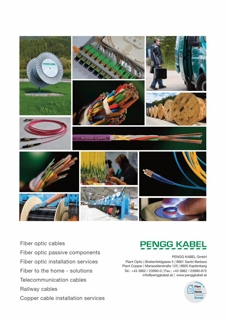
Fiber optic cables
Fiber optic passive components
Fiber optic installation services
Fiber to the home - solutions
Telecommunication cables
Railway cables
Copper cable installation services
PENGG KABEL GmbH Plant Optic | Breitenfeldgasse 5 | 8661 Sankt Barbara
Plant Copper | Mariazellerstraße 125 | 8605 KapfenbergTel.: +43 3862 / 23990-0 | Fax.: +43 3862 / 23990-672
[email protected] | www.penggkabel.at